


Abstract
Shaking tables are critical facilities for simulating seismic effects via ground motion reproduction. However, single-table tests are often constrained by limited platform dimensions and load capacity. While multi-table synchronization partially addresses these limitations, traditional array control methods under rigid connections face challenges, including degraded precision from synchronization errors and experimental interruptions due to output forces exceeding safety limits. To address high-precision synchronization requirements for rigid-connected dual-shaking table arrays, this study proposes an impedance-based internal force coordination control strategy. This approach enhances synchronization accuracy and helps prevent failures from excessive coupling forces. Specifically, a global simulation model and a mechanical model of the dual-shaking table array under rigid connection were established. Through simulation and experimental validation, the impact of synchronization errors was evaluated and the strategy’s efficacy was verified. Results show the strategy significantly reduces peak-force discrepancy between platforms. The method effectively circumvents experimental bottlenecks, such as output force saturation, inherently associated with rigid connections.
1. Introduction
Shaking tables are specialized facilities designed to simulate seismic actions by reproducing ground motion during earthquakes. These systems are widely utilized in seismic loading tests for various engineering structures [1,2,3]. Conventional shaking table tests typically employ a single platform; however, constraints such as platform dimensions and load-bearing capacity often fail to meet the experimental requirements for large-span or large-scale structures. Consequently, multi-platform table array systems have received extensive focus in recent years.
Nevertheless, achieving perfect control and coordination between different shaking tables within a multi-table array system remains challenging, making synchronization errors difficult to avoid. Under conditions involving a rigid connection of specimens, synchronization errors between multiple tables generate coupling forces that degrade platform performance and control precision. In severe cases, these errors can trigger overload protection mechanisms and lead to experimental failure [4,5,6], thereby limiting the application and efficacy of multi-table collaborative testing technologies.
The issues arising from the coupling of a dual-shaking table array through rigid specimens are essentially a dynamic, mutual interaction process between force and position [6]. Under the constraints of a rigid connection, control strategies based purely on position tracking can amplify minute synchronization errors into substantial coupling forces. This phenomenon may distort the actual motion trajectories transmitted to the specimen and potentially exceed the output capacity limits of the actuators, resulting in the interruption of the test. To address these challenges, traditional control methods have primarily focused on enhancing the control precision of shaking tables under multi-table coupling conditions. For instance, Guan et al. [4] proposed a synchronization control strategy based on a master–slave structure; Li et al. [5] developed a differential movement synchronous tracking control strategy aimed at compensating for the effects of specimen stiffness; Wang and Li [7] introduced a hybrid control strategy combining fuzzy logic control with adaptive inverse control to improve dual-shaking table synchronization and tracking accuracy; and Hu et al. [8] proposed a robust adaptive synchronization and tracking control strategy based on neural networks. While these studies have made notable progress in reducing displacement synchronization errors, their critiques of existing methods are largely implicit. For instance, most of these approaches treat the specimen as a passive load and do not explicitly model or compensate for the dynamic coupling forces that arise under rigid connections. As a result, they prioritize kinematic tracking accuracy over force interaction, which can lead to excessive internal forces when synchronization errors are inevitably present. However, the core objective of the synchronization control strategies presented in the aforementioned literature is to suppress synchronization errors and enhance tracking performance. Although progress has been made in eliminating coupling forces, most studies prioritize the minimization of displacement synchronization errors or the maximization of control precision without directly accounting for the coupling forces and their dynamic variations induced by inter-table interactions. Given that even minor displacement errors can generate significant coupling forces under rigid connection conditions, there remains room for improvement in existing methods for resolving multi-table coordination issues.
Implementing force control technology to achieve real-time consistency in contact forces between dual platforms is a fundamental approach to resolving multi-table coordination issues. To this end, researchers have proposed compliance control. Compliance control does not refer to a specific algorithm, but a collective term for techniques that regulate the response of a controlled object to external forces and motions through either control-based or mechanical means. Existing compliance control methods are categorized into passive compliance control and active compliance control. Passive compliance control achieves environmental adaptation by installing various highly flexible mechanical devices at the end-effectors [9,10,11]. While this approach offers the advantages of rapid response and low cost [12], its precision and adaptability are often compromised [13,14,15,16,17,18]. Active compliance control is realized by integrating force feedback with position control, primarily encompassing hybrid force/position control and impedance control. Although hybrid force/position control has been optimized through various methods such as sliding mode control and neural networks, it continues to face challenges, including complex controller design, heavy reliance on environmental modeling, and poor real-time performance [19,20,21,22,23]. In contrast, impedance control regulates the dynamic relationship between force and position by establishing a “mass-damper-spring” model. This allows the system to naturally adapt to environmental interactions, thereby demonstrating significant potential for resolving the aforementioned coupling problems.
Impedance control can be further classified into position-based impedance control and force-based impedance control [24,25]. Position-based impedance control offers the advantage of being easy to implement without requiring a precise dynamic model [26,27]. However, parallel mechanisms, such as multi-degree-of-freedom shaking tables, are characterized by complex dynamic coupling, non-linearity, and anisotropy. Obtaining a precise inverse dynamic model for such systems is difficult, and parameter tuning remains demanding, necessitating high system modeling accuracy. Consequently, the direct application of position-based impedance control to parallel mechanisms like shaking tables is significantly constrained. Therefore, to better adapt to the dynamic characteristics of parallel systems and reduce reliance on model precision, force-based impedance control strategies have gained increasing attention for such applications [28,29]. For instance, Haddadin and Shahriari [30] proposed a unified force-impedance control (UFIC) strategy, which aims to integrate the advantages of both impedance control and force control. Bonitz and Hsia introduced a scheme for the impedance control of cooperating manipulators based on internal forces. By enforcing a relationship between velocity and internal force, this approach directly imparts impedance characteristics to the manipulators, achieving simultaneous coordination of motion and internal forces without prior knowledge of object dynamics, while providing a rigorous proof of system stability [31]. Ba et al. [32] proposed an improved second-order dynamic compliance impedance control system, which significantly enhances control accuracy by rearranging the dynamic compliance composition and incorporating feedforward compensation.
However, research regarding impedance control for dual six-degree-of-freedom shaking table arrays remains relatively limited. Only a few studies have preliminarily verified the feasibility of such methods in other parallel systems [33,34,35], and to the best of our knowledge, a specialized impedance control design tailored specifically for dual-shaking table shaking table systems under rigid connection has not been fully developed in the existing literature, although general impedance frameworks have been applied to other parallel mechanisms. For instance, Caccavale et al. [36] proposed a general impedance control scheme for dual-arm robotic systems, combining both centralized and decentralized strategies. Similarly, Ba et al. [37] employed a dual-loop control structure to achieve object-level compliance control and internal load suppression for end-effectors.
Based on these discussions, this study addresses the synchronization control challenges of dual-shaking table array systems under rigid connection conditions by proposing an impedance-based internal force coordination control strategy for dual platforms. Unlike conventional impedance-based methods applied to parallel mechanisms [33,34,35], which typically rely on predefined reference forces or centralized coordination architectures, the core contribution of this work is threefold: (i) formulating the dual-shaking table synchronization problem as a mutual force coordination task rather than a pure displacement tracking problem; (ii) eliminating the need for a predefined desired force by using each platform’s measured contact force as the other’s reference; (iii) implementing a decentralized mutual force feedback architecture that does not require a master–slave hierarchy or an external force planner.
Specifically, this study is organized as follows. First, in Section 2, an impedance control strategy targeting real-time coordination of contact forces between the two tables is developed. This strategy generates position compensation values through a second-order discrete impedance filter, seamlessly integrating impedance control into the existing system. This approach suppresses the influence of coupling forces and overcomes the limitations of traditional methods that require pre-defined desired forces. Second, in Section 3, the presence of coupling forces and their detrimental effects on control precision and experimental progress are verified by establishing a comprehensive system simulation model, a rigid connection mechanical model, and a method for acquiring table platform forces. Furthermore, the effectiveness of the proposed strategy is validated under various frequency conditions through a combination of Simulink simulations and physical table array experiments.
2. Impedance Control Theory and Internal Force Coordination Control Strategy for Dual-Shaking Table Arrays
2.1. Impedance Control Theory
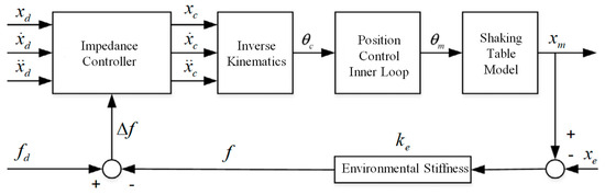
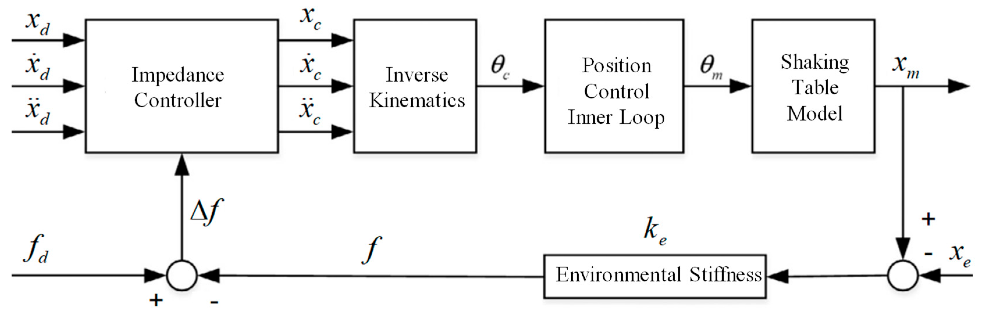
By regulating the dynamic relationship between system position and contact force, force-based impedance control enables the controlled object to achieve compliant motion and precise force tracking under rigid connection conditions. This approach suppresses excessive internal forces caused by motion asynchronization between the two tables. The fundamental principle of this control strategy is illustrated in Figure 1.
Figure 1.
Schematic diagram of impedance control.
In the figure, represent the desired displacement, velocity, and acceleration, respectively; denote the corrected displacement, velocity, and acceleration commands generated by the impedance controller; and signify the motor motion angle command and its corresponding actual output value. indicates the actual output displacement of the shaking table, while represents the external disturbance. denotes the environmental stiffness, then and represent the desired and actual forces exerted on the platform, respectively.
When the shaking table platform interacts with the external environment, its contact dynamics can be modeled as an equivalent second-order mass-spring-damper system. For the baseline case with zero desired contact force, the equation of motion is defined as follows:
where is the desired inertia coefficient, which reflects the system’s response characteristics to acceleration disturbances; is the desired damping coefficient, which governs system oscillation and energy dissipation; is the desired stiffness coefficient, which determines the system’s rigid response degree to external forces; are the virtual corrected command variables generated by the impedance model, respectively; are the desired displacement, velocity, and acceleration of the platform, respectively; and represents the actual contact force between the platform and the specimen, and the negative sign indicates that the measured contact force acts in the direction opposing the positive displacement correction. The measured platform displacement is assumed to track sufficiently closely under the high-bandwidth inner position-loop assumption.
This model characterizes the relationship between the actual motion and the desired motion. If the system is not in contact with the environment (), the platform can accurately track the commanded pose. Once contact occurs, the impedance model dynamically generates position corrections based on the force deviation. Figure 2 presents a schematic diagram of the impedance control model decoupling relationships.
Figure 2.
Schematic diagram of the impedance control model decoupling relationships.
To achieve force tracking, the force error is typically utilized as the input to the impedance model, where denotes the desired contact force. The modified equation of motion is presented in Equation (2):
Let x denote the corrected position command. The impedance-controller output is therefore defined as the desired position correction , and applying the property of the Laplace transform under zero initial conditions (where denotes the Laplace transform operator), Equation (3) is derived from the aforementioned equation as follows:
where represents the complex frequency variable in the Laplace transform, which converts the differential equation in the time domain (as shown in Equation (2) into an algebraic relationship in the frequency domain (as shown in Equation (3), thereby facilitating system analysis and controller design.
Consequently, the force-to-position compliance transfer function of the controller is obtained as Equation (4):
Here, denotes the desired mechanical impedance, whereas denotes the corresponding admittance, or force-to-position compliance transfer function, used by the controller.
In the frequency domain, this controller is equivalent to a second-order low-pass filter, where the cut-off frequency and damping ratio are determined by the impedance parameters. To facilitate the implementation of a digital controller, the continuous impedance model must be discretized. By utilizing the bilinear transformation method [38], the discrete-time difference equation is obtained as shown in Equation (5):
where is the position correction at time step , is the force error at time step , and are the discrete coefficients determined by , and the sampling period. These coefficients are calculated as .
Therefore, the five discrete coefficients are not independently tuned but are uniquely calculated from the selected impedance parameters and the controller sampling period. In the present implementation, is expressed in N and in mm; , , and are generalized virtual coefficients expressed in N·s2/mm, N·s/mm, and N/mm, respectively.
The difference equation can be solved online by utilizing the force error , where is acquired in real-time from force sensors or torque observers. This process generates a corrected position signal setpoint , which is subsequently transmitted to the position controller.
Impedance parameters directly influence system performance and stability. A smaller stiffness coefficient enhances system compliance and reduces contact force, which may come at the expense of diminished position tracking accuracy. An appropriately increased damping coefficient suppresses oscillations and improves stability, whereas excessive damping leads to sluggish system response. The inertia coefficient is a virtual inertia coefficient whose initial numerical value is selected with reference to the platform payload. For the isolated continuous impedance filter, positive impedance coefficients ensure basic stability, while a non-oscillatory response requires the damping ratio to satisfy . Therefore, the impedance parameters should satisfy the conditions specified in Equation (6):
However, for the proposed dual-shaking table arrays with mutual force feedback, the overall system stability is not guaranteed solely by the individual impedance conditions due to the dynamic coupling between the two platforms through the rigid specimen. A practical stability guideline for the coupled dual-shaking table system can be obtained from frequency-domain analysis of the closed-loop transfer matrix. Assuming identical impedance controllers and symmetric mechanical coupling, the characteristic equation of the coupled system decouples into in-phase and anti-phase modes. The anti-phase mode directly governs the relative motion between the two platforms and is expressed as:
where represents the equivalent coupling stiffness. To account for practical uncertainties, the coupling stiffness exhibits a maximum variation denoted as . For frequency-specific engineering screening, the stiffness variation is represented as an equivalent inertial variation. From a frequency-domain perspective, the force perturbation caused by at an operating frequency is equivalent to an inertial disturbance. Applying the dynamic equivalence principle yields the minimum required inertial compensation.
Combining this frequency-dependent inertial compensation with the baseline damping requirement for non-oscillatory single-system response leads to the following frequency-dependent engineering guideline:
This additional term is introduced to approximately characterize the influence of coupling-stiffness fluctuation in the frequency domain and to provide a conservative margin for engineering parameter selection. In the present study, remains relatively small under the tested rigid connection. Consequently, the original individual stability condition and non-oscillatory condition serve as the practical baseline, while Equation (9) is used only as an auxiliary engineering check for the coupled dual-table system. It should be emphasized that the above condition is not a rigorous engineering-oriented stability in the sense of Lyapunov or the small-gain theorem, as it involves the operating frequency as a variable rather than a fixed system parameter. Therefore, it is best interpreted as an engineering-oriented guideline derived from frequency-domain reasoning. A rigorous Lyapunov-based or small-gain stability proof for the coupled nonlinear system, accounting for parameter uncertainties, time-varying coupling, and frequency-dependent dynamics, remains an important direction for future investigation.
Based on these conditions, the specific values of , , and can be determined as follows:
is first assigned a numerical value with reference to the 340 kg shaking-table payload and is then treated as a virtual inertia coefficient. It is not equal to the physical mass itself. This value can be further increased if greater disturbance rejection is needed but must remain compatible with the inequality in Equation (6).
is then selected according to the desired force compliance: a lower reduces peak contact forces at the expense of position accuracy; a higher prioritizes tracking precision. The choice should also ensure that holds for the planned operating range to obtain a non-oscillatory impedance response.
is finally chosen to achieve an over-damped, non-oscillatory response while satisfying and the inequality. A typical approach is to first select a target damping ratio and then solve for , adjusting slightly via simulation to avoid force overshoot. Here, represents the dimensionless damping ratio that characterizes the oscillatory behavior of the second-order impedance system. When , the system exhibits an under-damped oscillatory response; when , the system achieves critical damping with the fastest non-oscillatory response; and when , the system becomes over-damped and avoids oscillatory compensation.
2.2. Impedance-Based Internal Force Coordination Control Strategy for Dual-Shaking Table Arrays
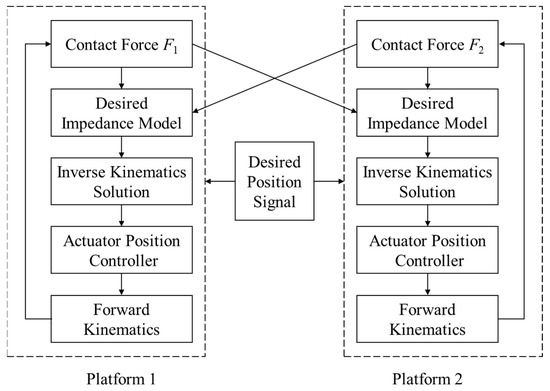
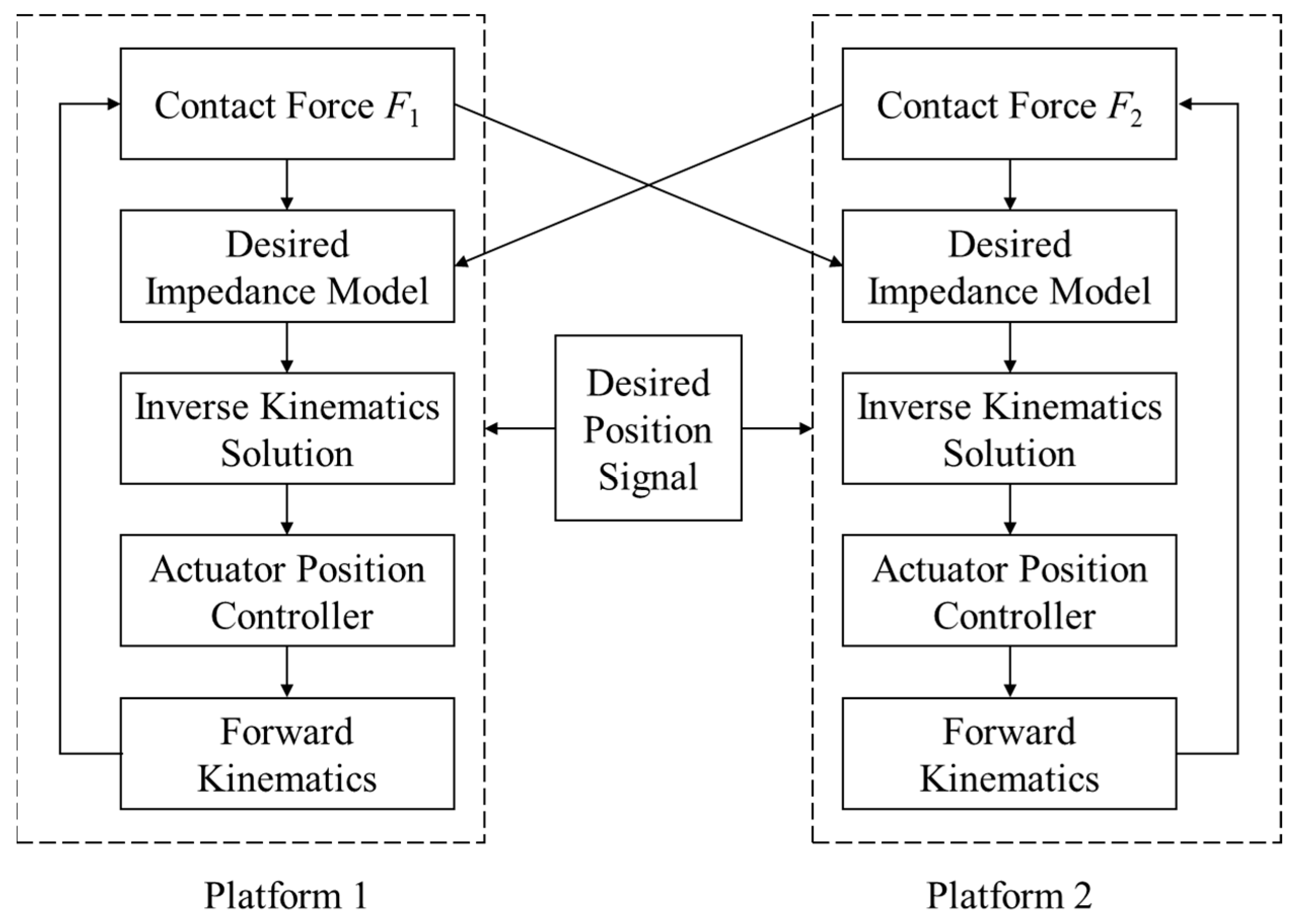
Although impedance control methods demonstrate potential for resolving synchronization issues in dual-shaking table arrays, the application of traditional algorithms is hindered by the difficulty of accurately defining the desired tracking force , which is influenced by multi-dimensional factors such as table kinematics, dynamics, time delays, and control errors. To address these challenges without requiring precise knowledge of the desired force, this study proposes an impedance-based internal force coordination control strategy specifically for dual-shaking table arrays. In contrast to conventional impedance control that requires a user-defined and prior multi-manipulator impedance schemes [31,36] that often rely on centralized coordination or internal force feedback from object dynamics models, the proposed method uses the real-time contact force measured from the opposite platform as the target force for each table. Furthermore, unlike prior impedance control applications in other parallel systems [33,34,35], this work introduces a mutual force feedback architecture as its key distinction. By coordinating the output forces of both platforms, this strategy suppresses additional coupling forces induced by synchronization errors and enhances system performance and stability. Furthermore, it eliminates the need for pre-defining or calculating a desired force value, thereby improving versatility and practical applicability. The core principle of the proposed strategy is to reduce the discrepancy between the two platforms and the specimen at equal magnitudes, thereby suppressing internal force imbalances caused by uncoordinated dual-shaking table motion. The system control structure is illustrated in Figure 3.
Figure 3.
Impedance-based internal force coordination control strategy flowchart.
Let and denote the real-time contact forces between the specimen and platform 1 and platform 2, respectively, which are obtained through force observation on the table platforms. The impedance control law for dual-platform internal force coordination can be designed as follows.
For platform 1, the measured force from platform 2 is utilized as the desired tracking force for platform 1. This force is then input into its corresponding impedance controller (a second-order discrete filter) to calculate the displacement correction increment :
where denotes the transfer function of the impedance controller for platform 1.
Similarly, the measured contact force of platform 1 is utilized as the desired tracking force for platform 2. This value is input into its respective impedance controller to calculate the displacement correction increment :
where denotes the transfer function of the impedance controller for platform 2.
By adding displacement corrections to the original trajectories and , new tracking commands are generated according to Equation (12). These are then converted into actuator commands through inverse kinematics for position servo control.
where and represent the original reference displacements for platform 1 and platform 2, respectively. and denote the displacement correction increments derived from the impedance control for platform 1 and platform 2. and are the corrected reference displacement commands for platform 1 and platform 2.
This strategy utilizes the force information from the dual-shaking table array as a mutual control objective, thereby eliminating the need for pre-defined desired force values and avoiding the challenge of accurately specifying in traditional impedance control. Simultaneously, by directly suppressing internal force coupling through force equilibrium, this approach is applicable to various specimen masses, connection stiffnesses, and motion trajectories, enhancing both system synchronization precision and stability.
3. Problem Analysis and Experimental Validation of the Dual-Shaking Table Array System
To investigate the synchronization control challenges of dual-shaking table array systems under rigid connection conditions, it is essential to first establish an accurate dynamic system model and analyze the underlying coupling mechanisms. Taking the Stewart platform dual-shaking table array system as an example, this section constructs a comprehensive mechanical model incorporating both platform dynamics and rigid connection characteristics. This model is utilized to verify the impact of coupling forces, induced by synchronization errors between the two tables, on system dynamic performance and synchronization precision. Furthermore, this section examines the effectiveness of the proposed impedance-based internal force coordination control strategy for dual-shaking table arrays.
3.1. System Modeling and Coupling Error Analysis for Dual-Shaking Table Arrays
3.1.1. Stewart Platform Modeling
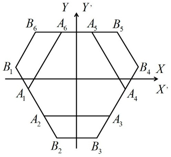
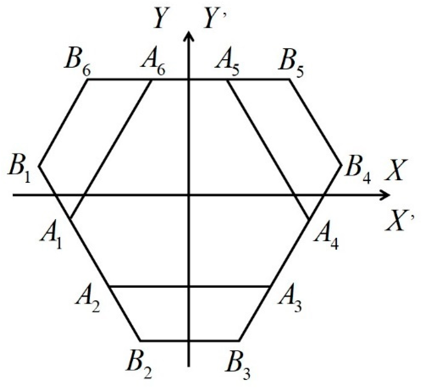
The Stewart platform uses six servo-electric cylinders as actuators; its geometric relationships are illustrated in Figure 4.
Figure 4.
Top view of the Stewart platform mechanism.
The conversion from motor torque to the linear thrust of each leg is given by the empirical formula obtained from energy conservation and calibrated with efficiency factors:
where is the transmission efficiency, is the lead of the ball screw, the transmission efficiency is set to based on the calibration tests. Therefore, is the corresponding dimensionless torque-to-thrust conversion coefficient. Equation (13) assumes a direct-drive ball-screw transmission without a reduction gearbox, with h expressed in metres per revolution.
To obtain the net contact force between the platform and the specimen, the vertical components of all six legs are summed and the inertial force of the platform is subtracted. As illustrated in Figure 4, the vertical component of a single leg is:
where represents the inclination angle between the leg and the horizontal plane, is the current height of the moving platform, and denotes the real-time length of the leg.
The total Z-axis force exerted on the platform is the summation of the Z-axis components from all six legs, adjusted by subtracting the inertial force generated by the platform mass undergoing Z-axis acceleration :
This calculation yields the net contact force between the platform and the specimen.
3.1.2. Mechanical Models for Rigid Connections
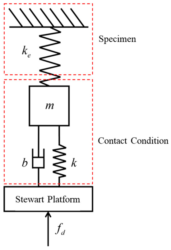
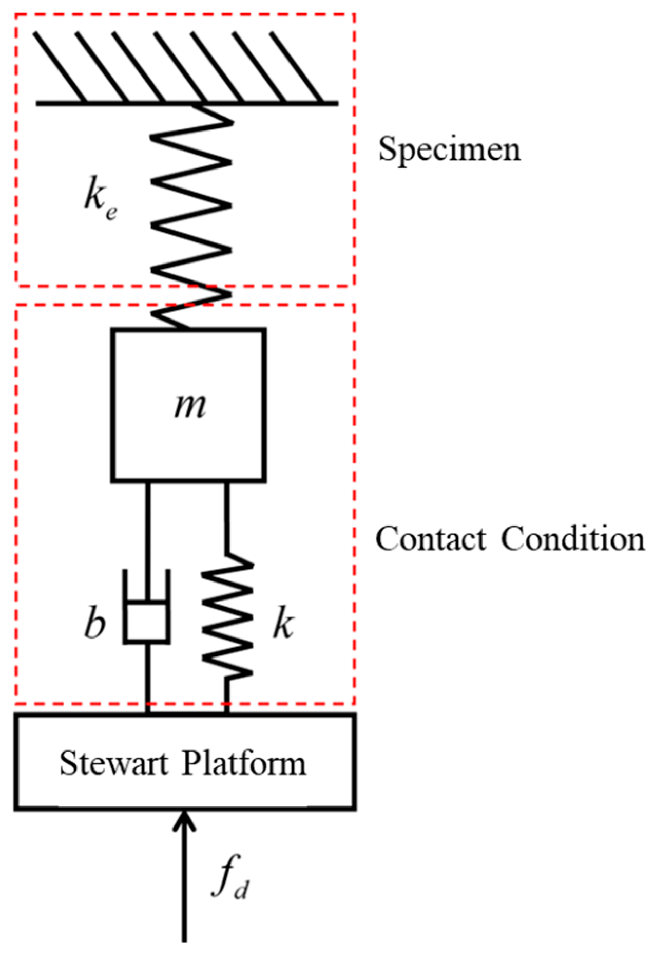
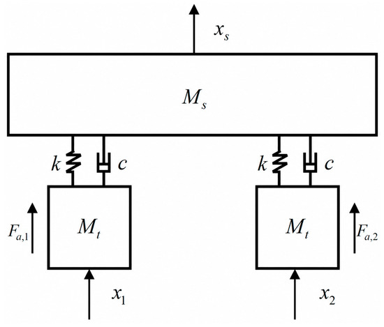
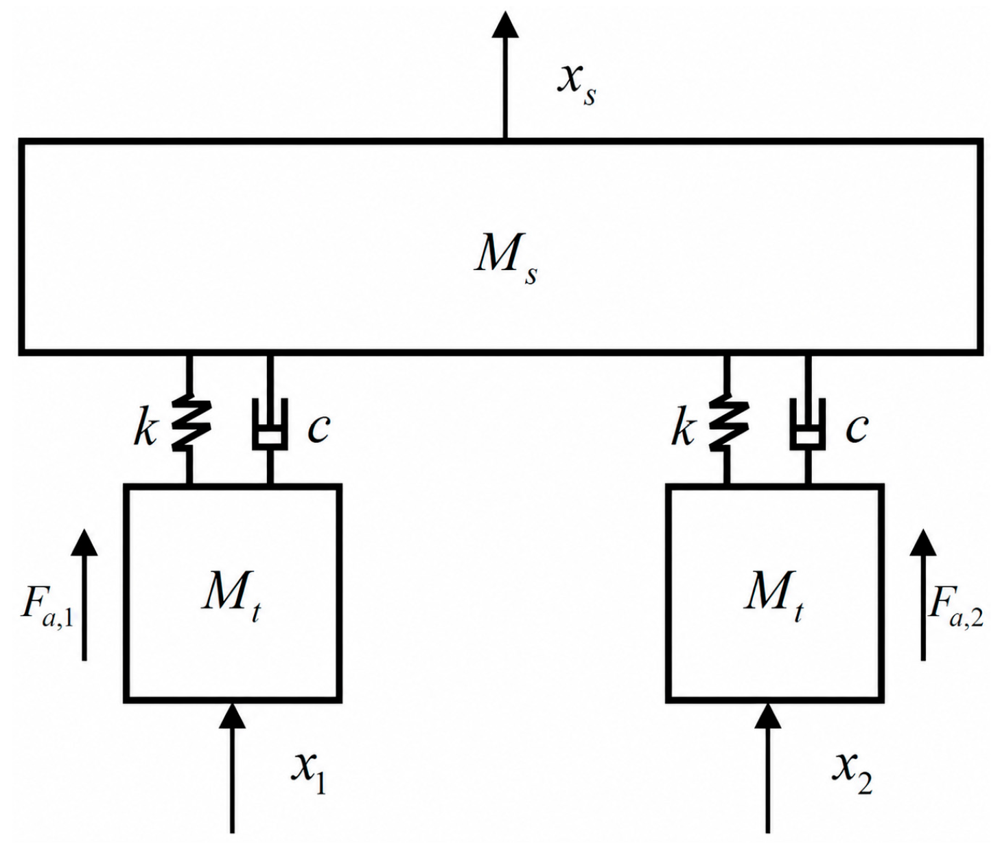
The rigid connection between the two platforms and the specimen can be modeled as an equivalent spring-mass-damper system, as shown in Figure 5. and denote the mass of the specimen and the table platform, respectively. and represent the actuation forces of platforms 1 and 2 after removing the static preload and the common-mode inertial contribution of the specimen. and denote the displacements of their respective platforms with respect to the static equilibrium position. represents the displacement of the center of the specimen, which is taken as under the assumption of rigid homogeneity; and represent the stiffness and damping of the coupling interfaces, which are small but non-negligible at high frequencies. Here, Fa,1 and Fa,2 are the effective actuation forces used in the incremental anti-phase model and are distinct from the measured contact forces F1 and F2 defined in Section 2.2.
Figure 5.
Rigid connection mechanical model of the dual-shaking table array.
To describe the internal coupling component associated with relative platform motion, a simplified incremental force-balance relation is introduced as follows:
Substituting the kinematic constraint for a rigid and homogeneous specimen yields the coupled dynamics:
where represents the table platform acceleration response of platform 1, and represents the table platform acceleration response of platform 2.
These equations show that synchronization errors directly generate coupling forces proportional to . This mechanical model provides the basis for understanding the coupling mechanism under rigid connection. It should be noted that Equations (16) and (17) are not intended to represent the complete absolute dynamic equilibrium of the specimen–platform system. Instead, they are used as an incremental anti-phase coupling model to characterize the additional internal force induced by the relative synchronization error between the two platforms. The static gravitational load of the specimen and the common-mode inertial load associated with the average specimen motion are assumed to be compensated by the static equilibrium of the test system or treated separately in the total contact-force evaluation. Therefore, these formulations are applicable only to the relative-motion component rather than to the absolute contact force or total actuator load.
3.1.3. Analysis of Synchronization Errors and Coupling Forces
To investigate the dynamic characteristics of the dual-shaking table array system under rigid connection conditions and to validate the existence and impact of coupling forces, this section conducts a comprehensive study of the system response under sinusoidal excitation with varying frequencies and amplitudes, integrating both simulation analysis and experimental testing.
Based on the previously established Stewart platform system model and the mechanical model for the dual-shaking table array with rigid connection, four typical sinusoidal displacement signal scenarios are selected for simulation analysis. The selection of experimental conditions strictly adheres to the effective operating frequency range of the Stewart platform (0.1–10 Hz) to ensure the validity and comparability of the system response. Within this broad range, the sub-range of 2 to 5 Hz is chosen for two reasons: (i) it avoids the very low frequencies below 1 Hz where the system behaves quasi-statically and coupling forces are minimal, and (ii) it excludes the upper frequencies above 6 Hz where displacement amplitudes become too small, specifically below 5 mm, to produce distinguishable coupling effects due to the physical limits of the platforms. The selected four frequencies of 2, 3, 4, and 5 Hz thus represent a typical mid-frequency band where synchronization errors pose significant challenges for rigid connections. The amplitude settings for each working condition are determined according to the frequency-amplitude envelope commonly utilized in engineering practice; specifically, the displacement amplitude is decreased as the frequency increases within the feasible motion range of the platform to generate a series of test conditions with equivalent dynamic intensity. The selected frequencies are 2 Hz, 3 Hz, 4 Hz, and 5 Hz, with corresponding amplitudes of 40 mm, 20 mm, 13 mm, and 8 mm, respectively. Consequently, the experimental findings are directly applicable to mid-frequency excitations; validation at lower or higher frequencies would require additional tests, though the proposed control framework itself is not inherently limited to this range.
Without the implementation of impedance control, the control algorithm used in the control experiments is the native PID control algorithm of the Stewart platform. Within the simulation model, a platform–specimen contact force of 6 kN is adopted as the nominal safety reference for evaluating potential overload conditions.
To better evaluate the control performance of the Stewart platform dual-shaking table array system, this study introduces three performance assessment metrics: time delay, root mean square error (RMSE), and peak error between the reference input r and the actual output y. These metrics enable a multi-dimensional quantitative analysis of simulation and experimental data from three distinct perspectives: dynamic response, steady-state precision, and extreme deviation. The details of these three indicators are summarized in Table 1.
Table 1.
Performance evaluation metrics for the Stewart platform.
In this table, denotes the reference input signal (displacement) for the -th channel at discrete time index , while represents the actual output signal (displacement) for the -th channel at the same time index, with the superscript indicating displacement (as acceleration is excluded per the study’s rigid-body assumption under sinusoidal excitation). The variable is the discrete time index, is the time lag index used in cross-correlation to compute , is the total number of samples in the evaluation window, and denotes continuous time in the peak error formula. All metrics are derived from displacement data to ensure sufficient evaluation of synchronization without requiring acceleration analysis.
Acceleration is not included as a separate performance metric in this study. The primary reason is that the control objective of this paper is to achieve force coordination between platforms, rather than high-precision displacement or acceleration tracking. Under rigid connection conditions, the specimen and the two platforms move together as a single rigid body; therefore, the acceleration of each platform is directly proportional to its displacement scaled by under sinusoidal excitation. Consequently, for the steady-state sinusoidal test conditions considered in this study, any improvement in displacement tracking accuracy directly implies a proportional improvement in acceleration tracking, and the force coupling effects of interest are already captured by the contact force analysis. Since the focus is on reducing coupling forces between platforms rather than pursuing independent acceleration control, displacement-based metrics are sufficient to evaluate the core issue of synchronization and internal force suppression. While displacement metrics are sufficient for steady-state sinusoidal analysis, acceleration data could provide additional insights into transient performance. We have therefore noted this as a future direction.
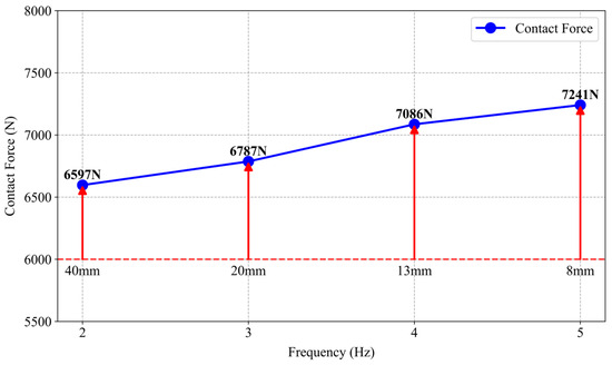
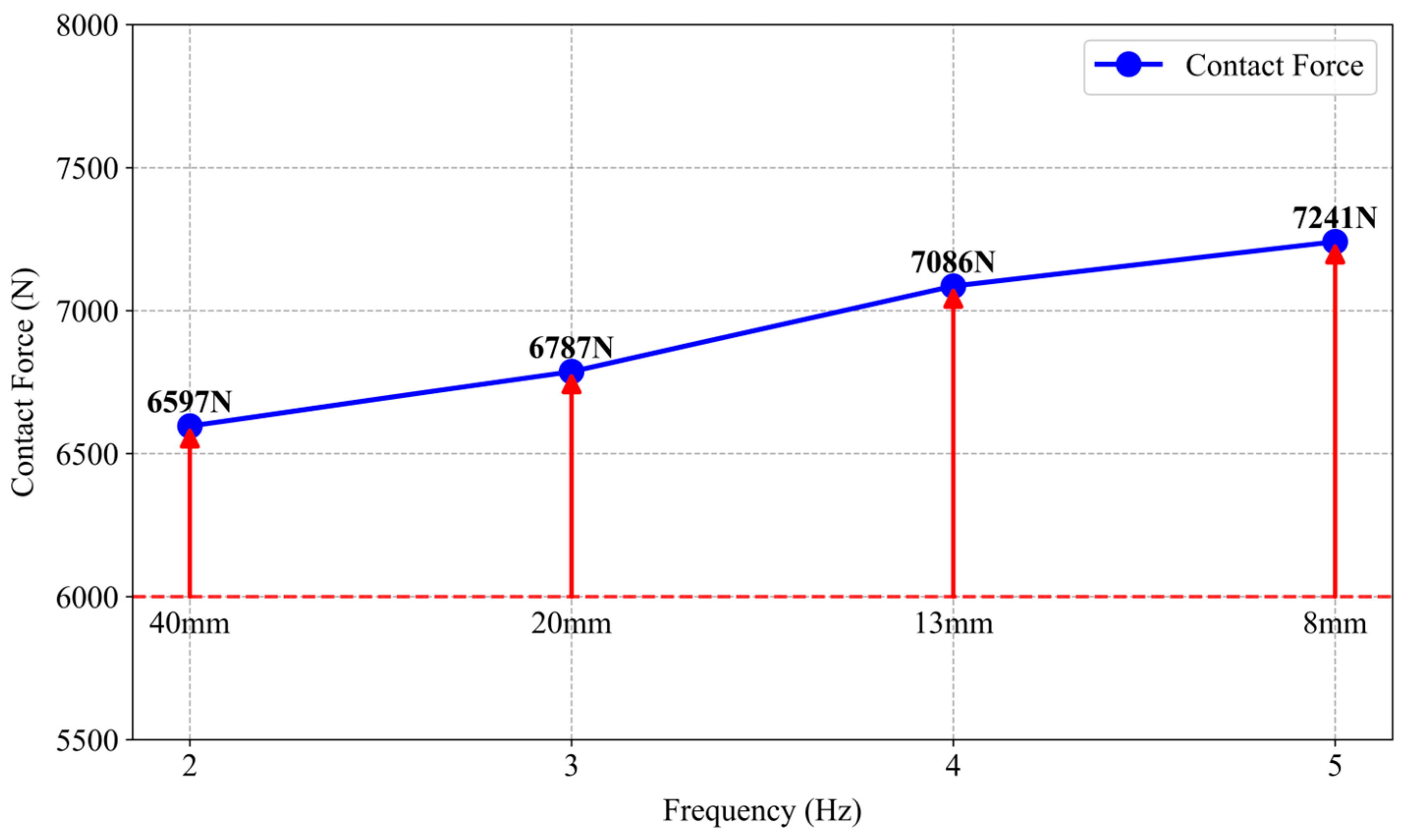
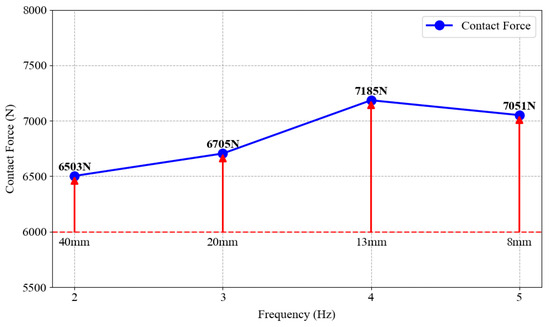
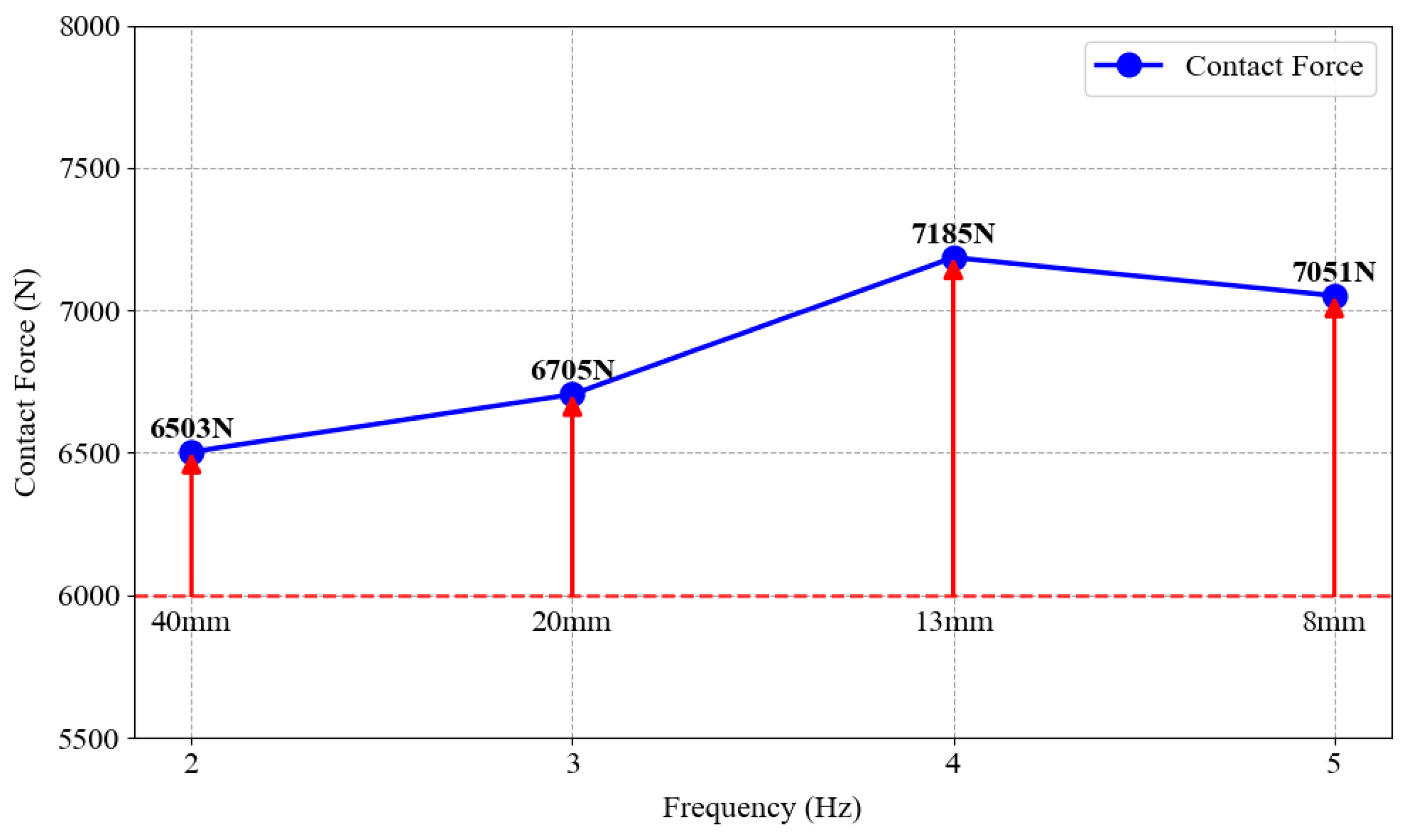
The simulation results demonstrate that under all tested working conditions, the peak contact force between platform 2 and the specimen slightly exceeds the nominal 6 kN reference. The peak contact force exhibits a positive correlation with the excitation frequency, as detailed in Table 2.
Table 2.
Comparison of uncontrolled peak contact force on platform 2 between simulation and experiment.
Figure 6 illustrates the peak contact force on platform 2 under simulation working conditions. Furthermore, the displacement reproduction accuracy decreases significantly as the frequency increases. As shown in Table 3, the root mean square error (RMSE) for platform 1 and platform 2 increases from 3.23% and 3.31% at 2 Hz to 14.03% and 14.53% at 5 Hz, respectively, indicating a substantial degradation in performance. Although the peak error remains relatively stable, ranging between 1.1% and 1.3%, the higher inertial forces generated during high-frequency motion imply that even smaller error magnitudes can trigger a system overload alarm.
Figure 6.
Peak contact force on platform 2 under simulation working conditions.
Table 3.
Simulation results of displacement reproduction for the dual-shaking table array.
It should be noted that the actual output force of the platform can exceed the maximum allowable load to a certain extent. Furthermore, the measurement range of the force instrumentation is capable of recording forces exceeding this limit. Therefore, peak contact forces greater than 6 kN may occur in practice. However, the control precision and operational stability of the platform cannot be guaranteed under such conditions. Consequently, 6 kN is adopted as the nominal safety threshold for both experimental and simulation studies in this research.
The simulation results indicate that the dynamic response capability of the controller degrades when the sum of the inertial forces and the coupling forces between the two platforms consistently approaches or exceeds the load limit. Meanwhile, dynamic coupling forces generated by uncoordinated dual-shaking table motion may significantly exceed the maximum allowable load of the platform. This is especially evident under high-frequency conditions and often leads to the termination of simulations or experiments. Such forces further exacerbate the tracking deviation of the system and exert a negative influence on the synchronization precision.
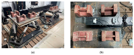
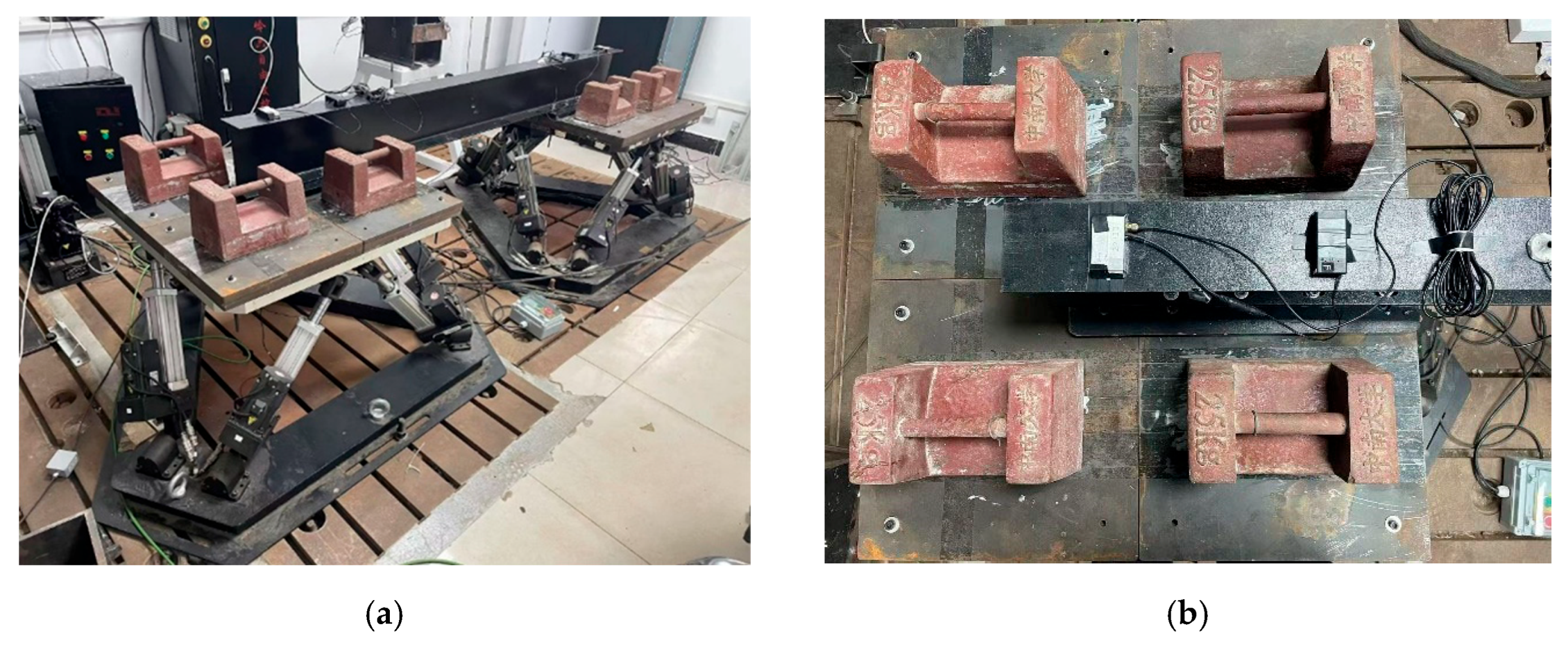
Subsequently, based on the simulation results of the dual-shaking table array system, corresponding experimental verification is performed on the Stewart platform dual-shaking table array system. The rigid specimen selected for the experiment is a 20a I-beam, designed and fabricated in accordance with the GB/T 706-2016 standard [39]. The I-beam is connected to the Stewart platform tables using steel plates to ensure a rigid connection. Additionally, appropriate supplementary masses are incorporated based on similarity design principles, as illustrated in Figure 7.
Figure 7.
Synchronous vibration test setup for the rigid-connected dual-shaking table array: (a) Dual-shaking table array loading test system. (b) Single-table load and connection configuration.
The experimental setup utilizes the same sinusoidal displacement signals as the simulation. We observed the contact force between the platforms and the specimen during the displacement reproduction process. We also evaluated the individual displacement reproduction accuracy of each platform and the overall synchronization performance of the dual-shaking table array. The results indicate that the peak contact force between platform 2 and the specimen is significantly high during the experiment. This high contact force triggers the overload protection mechanism, and this condition is shown in Figure 8.
Figure 8.
Experimental peak contact force on platform 2.
Experiments demonstrate that the time delay of the dual-shaking table array system remains at approximately 0.01 s. However, the system shows a significant degradation in displacement reproduction accuracy. The root mean square error of displacement tracking reaches 15.29% to 31.93%. The peak error ranges from 2.65% to 6.56%. The absolute value of the displacement synchronization error between the two platforms is small. The root mean square error does not exceed 0.68%, and the peak error does not exceed 0.2%. However, the dynamic coupling force effect is substantial due to the high structural stiffness of the components. These results are detailed in Table 4.
Table 4.
Displacement reproduction accuracy comparison between the rigid-connected dual-shaking table array and a single Stewart platform.
Simulation and experimental results demonstrate that under rigid connection conditions, even minor synchronization errors are converted into substantial additional internal forces due to motion constraints. These internal forces not only cause instantaneous platform overloading and trigger protection mechanisms but also significantly degrade both tracking and synchronization accuracy.
3.2. Simulation Validation and Analysis
To validate the effectiveness of the impedance-based internal force coordination control strategy, this section conducts synchronized vibration simulation research based on the rigid connection model established in Section 3.1.2. The simulation incorporates dual-platform interactive force coordination impedance control. The testing frequencies and amplitudes are identical to those in the previous experiments, covering the following four sinusoidal displacement signal working conditions: Working Condition 1: 2 Hz, 40 mm; Working Condition 2: 3 Hz, 20 mm; Working Condition 3: 4 Hz, 13 mm; and Working Condition 4: 5 Hz, 8 mm.
The controller uses the admittance transfer function G(s) defined in Equation (4).
For parameter selection, the impedance parameters are initially screened analytically based on platform dynamics and the non-oscillatory condition of the second-order impedance model, and then tuned offline through simulation. The inertia coefficient is set to 340 N·s2/mm. Its numerical value was initialized with reference to the 340 kg payload; it is a virtual inertia coefficient rather than the physical mass itself. The damping coefficient is set between 4600 and 4800 N·s/mm. This range is chosen to satisfy and from Equation (6) for all values used, indicating an over-damped non-oscillatory impedance response. To balance force control precision with stability, the stiffness coefficient is designed to decrease as the frequency increases, transitioning gradually from 800 to 590 N/mm. Specifically, a higher , such as 800 N/mm at 2 Hz, is adopted at low frequencies to prioritize position tracking accuracy; whereas a lower , such as 590 N/mm at 5 Hz, is selected at high frequencies to enhance compliance and reduce coupling forces, thus preventing force saturation.
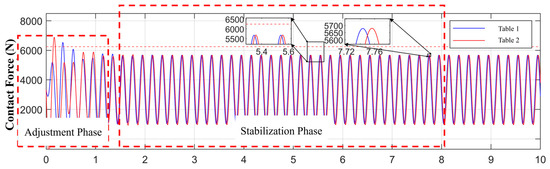
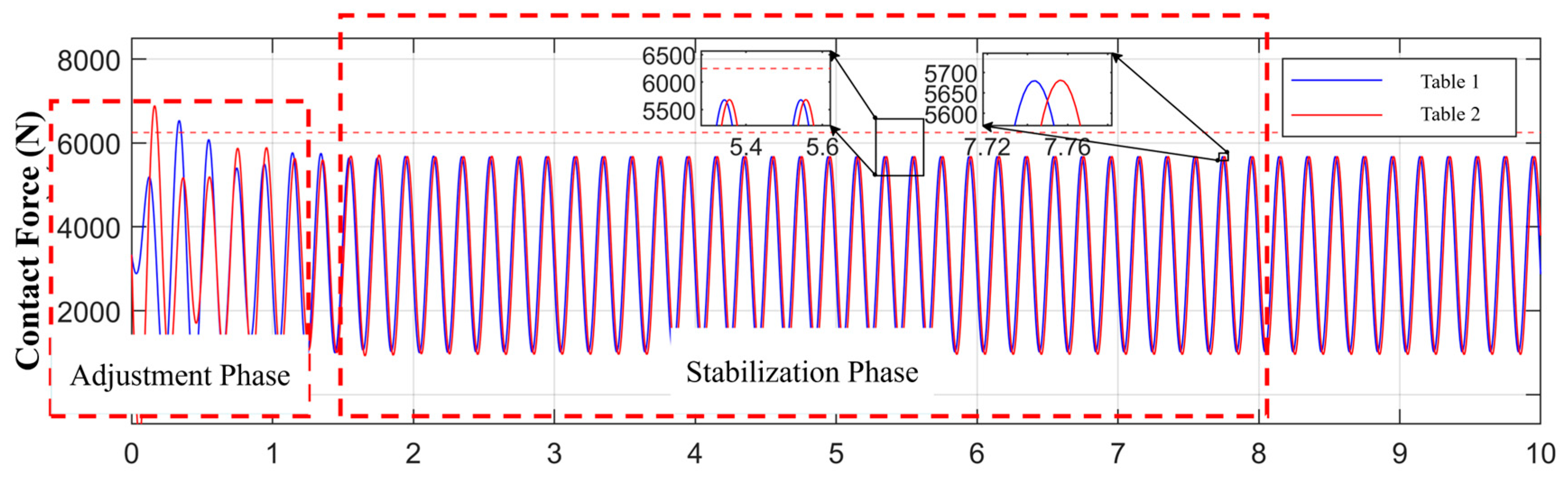
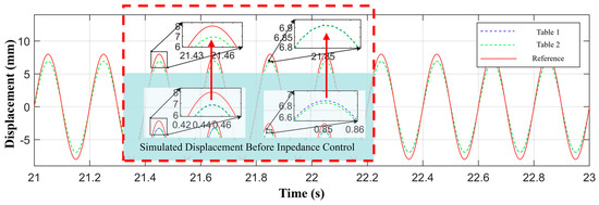
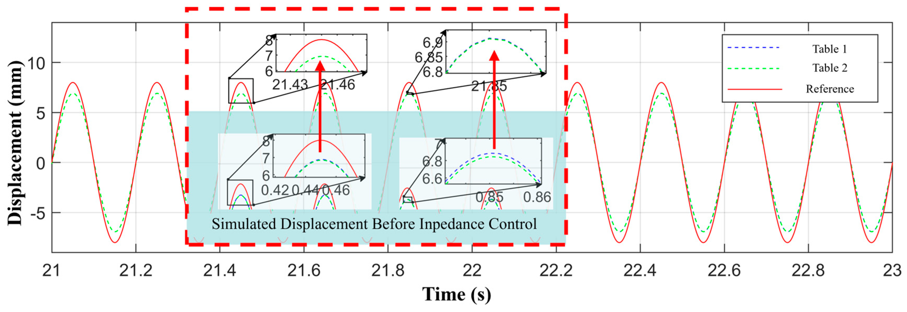
The simulation results demonstrate that the proposed impedance-based internal force coordination control strategy reduces the contact force between the platform and the specimen across different frequencies, maintaining it below the maximum allowable load of the platform. Taking the sinusoidal working condition with a frequency of 5 Hz and an amplitude of 8 mm as an example, the adjustment phase is defined as the transient period from the activation of the impedance controller until the contact force reaches a steady state; whereas the stabilization phase is defined as the subsequent period during which the peak contact forces in consecutive cycles exhibit no systematic drift and the force waveform consistently repeats cycle by cycle. Once the contact force stabilizes, the average peak values for platform 1 and platform 2 are 5669 N and 5688 N, respectively, resulting in a peak-force discrepancy of 19 N between the two tables. These results are illustrated in Figure 9 and Figure 10, and Table 5.
Figure 9.
Platform-specimen contact forces under impedance-based internal force coordination control in simulation.
Figure 10.
Displacement reproduction under impedance-based internal force coordination control in simulation.
Table 5.
Comparison of dual-shaking table interaction forces before and after impedance control in simulation.
As the frequency increases, the proposed control strategy maintains stable operation under the tested conditions by using frequency-scheduled impedance parameters selected offline, specifically by reducing the stiffness coefficient and optimizing the damping coefficient. At 3 Hz, the peak-force discrepancy between the two tables is 18 N; at 4 Hz, it is 9 N; and at 5 Hz, it is 19 N. Furthermore, the displacement reproduction errors remain within acceptable limits across all tested frequencies.
Compared to the baseline data obtained prior to the implementation of the proposed strategy, as detailed in Table 5, the peak contact force on platform 2 decreases significantly under all working conditions following the application of the force control. This evidence confirms that the proposed impedance-based internal force coordination control strategy partially eliminates the additional forces induced by synchronization errors under rigid connection conditions.
The simulation data for the dual-shaking table array system after applying the proposed strategy are presented in Table 6. A comparison between these results and the simulation data from the dual-shaking table array system without the implementation of this strategy indicates that the proposed control scheme enhances the synchronization control precision of the Stewart platform dual-shaking table array system. Consequently, the simulation results demonstrate the effectiveness of the impedance-based internal force coordination control strategy for dual-shaking table arrays in addressing the challenges associated with rigid specimens under rigid connection conditions.
Table 6.
Simulation results of displacement reproduction for the dual-shaking table array under impedance control.
3.3. Experimental Validation and Analysis
To validate the effectiveness of the impedance-based internal force coordination control strategy for dual-shaking table arrays in a practical system, this section presents the results of synchronous vibration experiments. These experiments are compared with test cases where the strategy was not applied. The experiments utilize the same four sinusoidal displacement signal working conditions as established in Section 3 (2 Hz–40 mm, 3 Hz–20 mm, 4 Hz–13 mm, and 5 Hz–8 mm). As shown in Table 7, after implementing the impedance-based internal force coordination control strategy for dual-shaking table arrays, the system successfully avoids the protection alarms previously triggered by sustained or excessive platform 2 overloading. The dual-shaking table array system operates stably and completes tests under all working conditions.
Table 7.
Experimental contact force comparison before and after impedance control.
Regarding contact force control, the peak contact force of platform 2 at all frequencies decreases significantly following the application of the control strategy, with an average reduction of 15.09%. These values remain below or slightly exceed the maximum allowable load of the platform. Although the peak-force discrepancy between the two shaking tables increases with frequency, the force control strategy suppresses the coupling forces induced by the rigid connection, ensuring the continuity of the experiment.
It should be noted that the peak-force discrepancy between the two shaking tables is higher in the physical experiments than in the simulation working conditions. This is attributed to factors such as model errors, parameter uncertainties, sensor noise, time-delay effects, and unmodeled nonlinear dynamics (e.g., friction and backlash) that are not fully captured in the idealized simulation model.
More importantly, the peak-force discrepancy increases significantly as the excitation frequency rises, increasing from 57 N at 2 Hz to 696 N at 5 Hz, as detailed in Table 7. This trend arises because: (i) the inertial force of each platform grows with the square of frequency, making the force measurement more sensitive to phase lags caused by sensor dynamics and tracking delay; (ii) although the nominal impedance damping ratio remains in the over-damped range for all tested parameters, the relative damping effect becomes less dominant under higher-frequency excitation because inertial and phase-lag effects increase, resulting in larger transient force errors; (iii) unmodeled leg friction and backlash become more pronounced at higher velocities, contributing to asymmetric force responses between the two tables. Within the tested range (2–5 Hz), however, the peak-force discrepancy remained below 700 N and did not trigger overload protection, indicating that the method is effective under the tested conditions.
Regarding robustness, the proposed impedance-based coordination strategy does not explicitly compensate for time delays or sensor noise. A small time delay in the force feedback loop can introduce an additional phase lag in the admittance filter defined in Equation (4), potentially reducing the effective damping. Similarly, force sensor noise with standard deviation leads to a displacement correction error of approximately , which may cause minor chattering. However, because the impedance controller acts as a low-pass filter (cut-off frequency determined by , , ), high-frequency noise is inherently attenuated. In all physical experiments, the observed force discrepancies remained within acceptable bounds (Table 7), and no instability or excessive chatter occurred, indicating that the method exhibits a certain degree of practical robustness against moderate levels of time delay (approximately 0.01 s, as shown in Table 8) and sensor noise. For larger delays or stronger parameter uncertainties, the control performance may degrade; therefore, future research will explore adaptive impedance control, robust control strategies, or multi-sensor information fusion technologies to further improve robustness and precision [40,41,42].
Table 8.
Experimental results of displacement reproduction for the dual-shaking table array under impedance control.
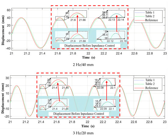
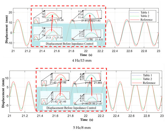
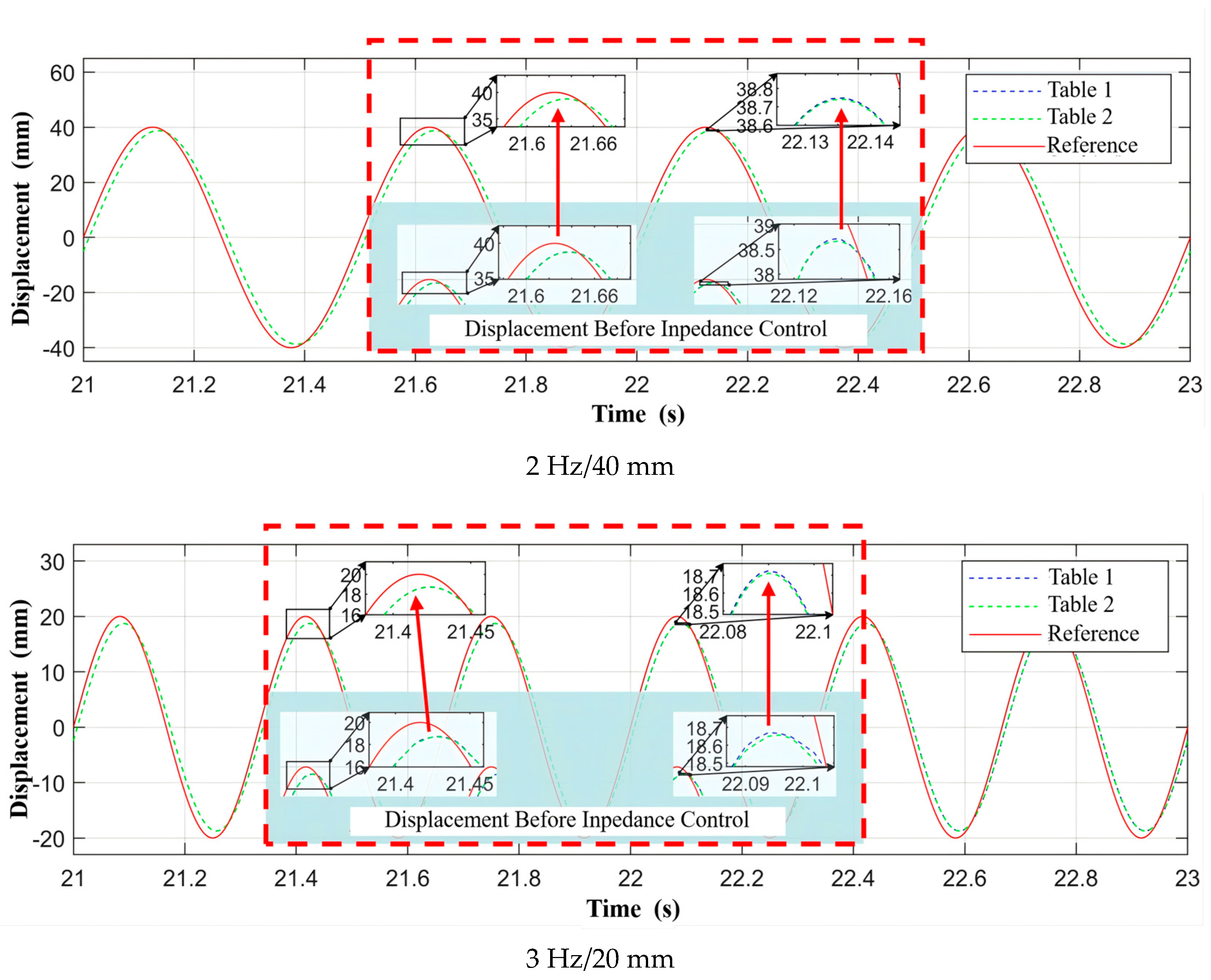
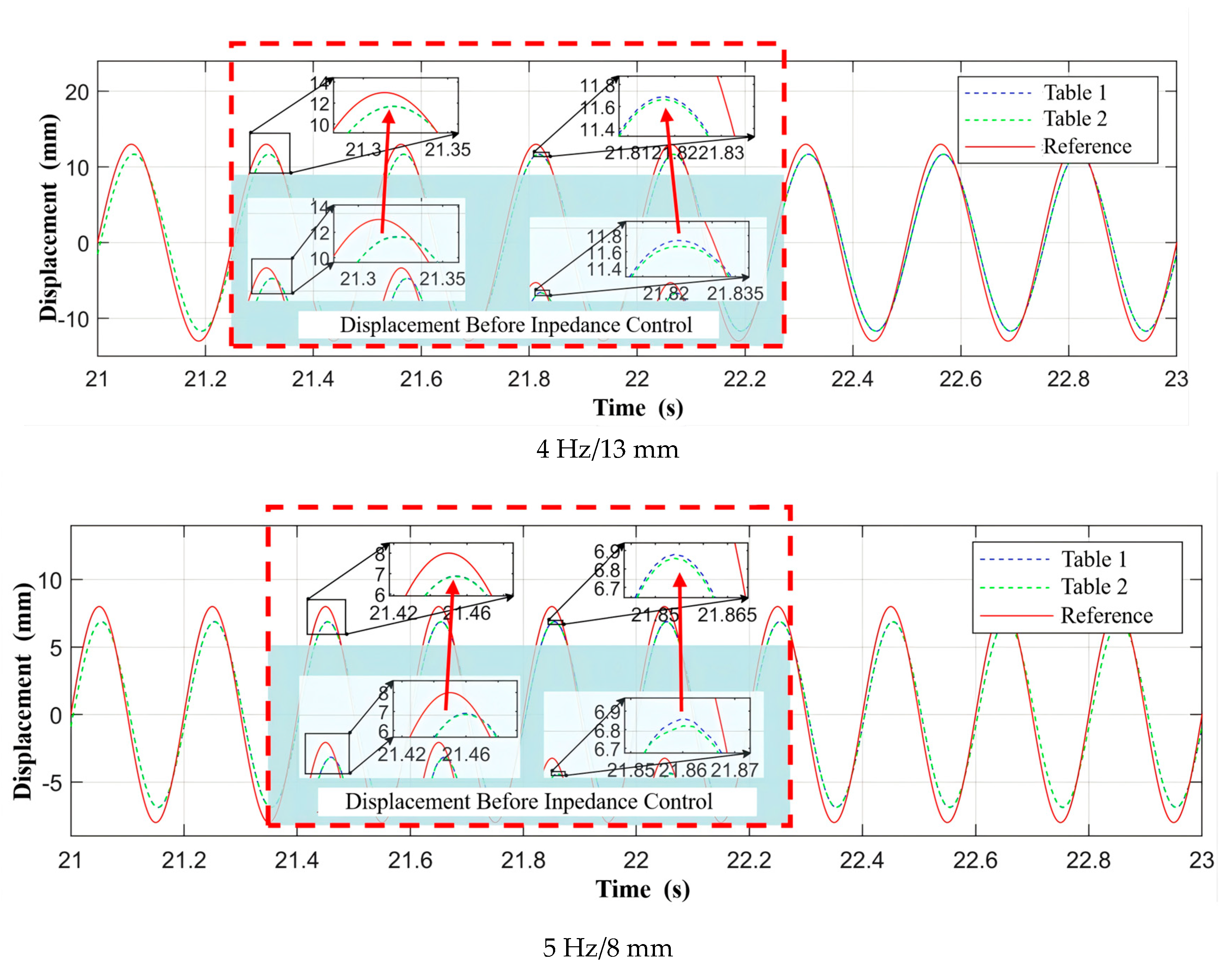
Regarding displacement synchronization accuracy, the system performance improves significantly after implementing the impedance-based internal force coordination control strategy for dual-shaking table arrays. The root mean square error of dual-shaking table synchronization decreases from 0.22% to 0.03% at 2 Hz, from 0.32% to 0.05% at 3 Hz, from 0.49% to 0.13% at 4 Hz, and from 0.68% to 0.29% at 5 Hz. As illustrated in Figure 11, the consistency of the displacement output between the two platforms improves markedly, which validates the effectiveness of the control strategy in enhancing synchronization precision.
Figure 11.
Displacement synchronization curves before and after impedance-based internal force coordination control.
However, the individual platform displacement reproduction RMSE remains relatively high, ranging from 15% to 32% across all tested frequencies, as detailed in Table 8. One of the main reasons stems from the time delay. In addition, the remaining RMSE and peak error originate from the following aspects. First, the essence of impedance control is force control, and its primary objective is to ensure force coordination across the table array. To achieve this, the controller intentionally makes fine adjustments to the given displacement reference signals. Consequently, a relatively high RMSE between the fine-tuned displacement output and the original reference signal is acceptable, as high-precision absolute displacement control is not the goal of this strategy. Achieving high-precision displacement tracking would require a separately designed controller. This also highlights a limitation of the proposed method: it cannot simultaneously guarantee high-precision absolute displacement control while ensuring force coordination, as their focal points differ. Second, a single, standalone Stewart platform under the same test conditions already exhibits similar RMSE values, spanning from 14.82% to 30.64%, as indicated in Table 4. Therefore, the elevated RMSE partly stems from the platform’s baseline tracking performance rather than the proposed coordination strategy alone. The fact that the dual-shaking table synchronization RMSE stays within 0.03% to 0.29%, which is much smaller than the individual RMSE, indicates that the two platforms track each other consistently, even if they both deviate from the desired trajectory. This is acceptable for the specific rigid-connection coordination problem, where the relative displacement between the platforms is often of greater significance than their absolute positions.
4. Discussion
The experimental and numerical investigations conducted in this study confirm that an impedance-driven force coordination framework can neutralize the destabilizing coupling effects inherent in rigidly connected dual-shaking table configurations. By dynamically balancing inter-platform interaction loads through mutual force feedback and a discrete impedance filter, the proposed control architecture successfully prevents actuator saturation while simultaneously enhancing inter-table synchronization across the tested frequency spectrum. These outcomes validate the initial working hypothesis that treating multi-table synchronization as a dynamic force-position interaction problem, rather than a purely kinematic tracking task, yields superior robustness under rigid constraint conditions.
Interpreting these results in light of prior research reveals a clear methodological shift. Conventional multi-table control architectures have predominantly prioritized displacement error minimization, frequently employing master–slave hierarchies, differential tracking schemes, or data-driven compensators. While such approaches improve kinematic alignment, they often overlook how minute positional mismatches can be rapidly amplified into substantial internal loads when rigid specimens couple the platforms. Hybrid force/position strategies and passive compliance devices have been explored as alternatives, yet they typically demand intricate controller tuning, heavy reliance on accurate environmental models, or exhibit limited adaptability to varying payload characteristics. In contrast, the present methodology circumvents the need for predefined force setpoints, which are notoriously difficult to estimate accurately due to system nonlinearities, time delays, and shifting dynamic loads. By allowing each platform to adaptively reference the other’s measured contact force, the controller inherently suppresses load imbalances without requiring complex inverse dynamics or extensive parameter identification. This design philosophy not only simplifies implementation but also enhances the system’s resilience to model uncertainties.
The broader implications of these findings could be meaningful for structural engineering and seismic testing practices. The demonstrated capacity to maintain stable operation under rigid specimen configurations significantly expands the experimental envelope for large-scale or multi-component structural systems that exceed the capacity of single-table facilities. The substantial reduction in inter-platform force discrepancies observed in physical trials directly translates to improved data reliability, extended equipment service life, and a markedly lower risk of premature test termination due to overload protection triggers. Moreover, the model-agnostic nature of the control architecture facilitates straightforward integration into existing shaking table infrastructure, lowering the technical and financial barriers for widespread adoption in academic and industrial testing centers.
Despite these advancements, certain limitations must be acknowledged. Physical experiments consistently exhibited higher force deviations compared to numerical simulations. This discrepancy is attributable to real-world nonlinearities that were idealized in the simulation environment, including joint friction, mechanical backlash, sensor measurement noise, communication latency, and parameter drift under prolonged operation. Furthermore, the theoretical stability analysis of the coupled dual-shaking table system remains incomplete: the condition given in Equation (6) is strictly valid only for a single impedance-controlled system. For the dual-shaking table array with mutual force feedback, a stability condition is derived in Section 2.1 for parameter selection, but a full Lyapunov-based proof accounting for parametric uncertainties and time-varying coupling is not provided. Equation (9) should not be interpreted as a rigorous sufficient stability condition, because it is derived from frequency-domain equivalence at a specified operating frequency and does not fully account for parameter uncertainties, time-varying coupling, tracking delays, or nonlinear dynamics. Nevertheless, within the tested frequency range of 2 to 5 Hz and using the current experimental setup, which featured a tracking delay of approximately 10 ms and a noise level below 2%, no instability was observed. Additionally, the current implementation relies on a pre-scheduled adjustment of impedance coefficients across different frequency bands. While effective for steady-state sinusoidal excitations, this approach may require further refinement to handle highly transient or broadband seismic waveforms without manual intervention.
It should also be clarified that the force discrepancy reported was calculated as the difference between the peak force magnitudes of the two platforms, rather than as the instantaneous pointwise difference. Therefore, this metric should not be interpreted as a complete measure of real-time force-matching performance. This choice was made because the primary engineering objective of the present study is to reduce the peak force demand on each individual platform and thereby prevent overload-induced test interruption. Nevertheless, the instantaneous force difference may contain additional phase-dependent components that are not fully captured by the present metric. A pointwise evaluation based on the maximum or root-mean-square value will therefore be considered in future investigations.
More importantly, the practical limits of the proposed method are threefold. First, although the control framework is theoretically applicable to a broader frequency band, the current validation is restricted to the 2–5 Hz mid-frequency range. At higher frequencies, the required displacement amplitude drops below 5 mm due to the platform’s physical limits, making coupling effects hard to be tracked and monitored. Second, the method assumes a perfectly rigid and homogeneous connection; significant specimen flexibility or asymmetric stiffness would invalidate the kinematic constraint to some extent. Third, validation is currently limited to uniaxial vertical motion; multi-axial excitations would require expanding the single-axis filter to a full six-degree-of-freedom formulation. Within these bounds, the method is effective; beyond them, adaptive extensions are needed.
Future research will focus on embedding adaptive or learning-based mechanisms for real-time impedance tuning, alongside multi-sensor data fusion to mitigate noise and time-delay effects. Expanding the framework to accommodate three or more synchronized tables and validating it under complex multi-axial earthquake records will further evaluate its scalability. Additionally, acceleration-based metrics will be incorporated for non-stationary inputs where displacement alone is insufficient. Finally, exploring digital twin technologies could enable predictive load management for autonomous testing environments. Overall, by shifting the paradigm from rigid position tracking to adaptive force equilibrium, this strategy offers a pragmatic solution to longstanding challenges in collaborative seismic testing.
5. Conclusions
This study addresses the coupling force problem in Stewart platform dual-shaking table array systems under rigid connection conditions. An impedance-based internal force coordination control strategy is proposed, and its effectiveness is validated through system simulation and experimental research. The primary conclusions are as follows:
- An impedance-based internal force coordination control strategy for dual-shaking table arrays is developed. This method utilizes the measured contact forces of the two platforms as the target forces for each other. It employs a second-order discrete impedance filter to generate displacement corrections and promotes dynamic coordination of internal forces between the tables. Distinct from traditional impedance control that requires a predefined , as well as prior multi-table coordination methods [4,5,7] that focus primarily on reducing displacement synchronization errors, this method eliminates the need for preset target forces and instead uses mutual force feedback between the two platforms. Unlike traditional impedance control, this method eliminates the need for preset target forces. This approach helps reduce control deviations caused by inaccurate force settings and offers good adaptability and engineering practicality, particularly for rigidly connected dual-shaking table arrays where displacement-based methods alone are insufficient.
- A synchronous vibration simulation model for the Stewart platform dual-shaking table array system under rigid connection is established. This model reveals the mechanism behind the system issues caused by rigid specimens, providing a reliable basis for controller design.
- Simulation and experimental results demonstrate that the proposed control strategy suppresses coupling forces and significantly improves system performance. In simulation, the peak-force discrepancy between table platforms is reduced. The strategy substantially reduces the platform peak-force demand and prevents sustained overload-induced test interruption. It also enhances synchronization control stability, while the displacement reproduction accuracy improvement is a secondary benefit compared to the primary control objective of force coordination.
Author Contributions
Conceptualization, W.G.; Methodology, X.L. and J.L.; Software, X.L., C.S., J.L. and Z.S.; Validation, W.G., C.S., J.L. and Z.S.; Formal analysis, W.G., X.L. and Y.X.; Investigation, W.G. and C.S.; Resources, C.S.; Data curation, X.L., C.S., J.L. and Z.S.; Writing—original draft, X.L.; Writing—review & editing, W.G., X.L. and Y.X.; Visualization, X.L. and J.L.; Supervision, W.G. and Y.X. All authors have read and agreed to the published version of the manuscript.
Funding
This study is supported by the following funding: Science and Technology Research and Development Program Project of China Railway Group Limited (2023-Major-20), Natural Science Foundation of China (U2368210), and Fundamental Research Project of China Railway Group (L2024G015(T001)).
Data Availability Statement
The data used to support the findings of this study are available from the corresponding author upon request.
Conflicts of Interest
Authors Wei Guo and Yongjia Xu were employed by the company China Railway Group Limited. The remaining authors declare that the research was conducted in the absence of any commercial or financial relationships that could be construed as a potential conflict of interest. The authors declare that this study received funding from China Railway Group Limited. The funder was not involved in the study design, collection, analysis, interpretation of data, the writing of this article or the decision to submit it for publication.
References
- Zhao, F.; Yu, S.B.; Li, B.; Shi, Z. Research Advances on Large-Scale Shaking Table Test for Rock Slopes under Earthquake. Earth Sci. 2022, 47, 4498–4512. [Google Scholar]
- Ding, Y.; Dong, Y.Q.; Shi, Y.D. State-of-the-Art on Seismic Isolation of Long-Span Spatial Structures. J. Southeast Univ. Nat. Sci. Ed. 2023, 53, 857–868. [Google Scholar] [CrossRef] [Scilit]
- Guan, M.Z.; Guan, K.S.; Wang, T.C. Summary of Shaking Table Test Research on Anti-Dipping Rock Slope. Earthq. Resist. Eng. Retrofit. 2021, 43, 157–167. [Google Scholar]
- Guan, G.F.; Xiong, W.; Wang, H. Control of a Dual Shaking Tables Vibration Test System. J. Vib. Shock 2017, 36, 207–211. [Google Scholar]
- Li, X.; Wang, J.; Li, F.; Li, N.; Huang, H. Differential Movement Synchronous Tracking Control Strategy of Double-Shaking Table System Loading with Specimen. Shock Vib. 2018, 2018, 1785184. [Google Scholar] [CrossRef] [Scilit]
- Yu, H.T.; Chen, X.Z.; Li, P. Analytical Solution for Design Parameters of Model Box to Simulate Seismic Spatial Variability Effect Using Double-Array Shaking Tables. Chin. J. Geotech. Eng. 2020, 42, 1428–1434. [Google Scholar]
- Wang, J.; Li, F. Synchronous Tracking Control Strategy of Dual-Actuator Excited Shaking Table. Int. J. Struct. Stab. Dyn. 2025, 25, 2550215. [Google Scholar]
- Hu, S.; Ren, X.; Zheng, D.; Chen, Q. Neural-Network-Based Robust Adaptive Synchronization and Tracking Control for Multimotor Driving Servo Systems. IEEE Trans. Transp. Electrif. 2024, 10, 9618–9630. [Google Scholar] [CrossRef] [Scilit]
- Wei, Y.; Xu, Q. Design of a New Passive End-Effector Based on Constant-Force Mechanism for Robotic Polishing. Robot. Comput.-Integr. Manuf. 2022, 74, 102278. [Google Scholar] [CrossRef] [Scilit]
- Chen, F.; Zhao, H.; Li, D.; Chen, L.; Tan, C.; Ding, H. Contact Force Control and Vibration Suppression in Robotic Polishing with a Smart End Effector. Robot. Comput.-Integr. Manuf. 2019, 57, 391–403. [Google Scholar] [CrossRef] [Scilit]
- Du, H.; Sun, Y.; Feng, D.; Xu, J. Automatic Robotic Polishing on Titanium Alloy Parts with Compliant Force/Position Control. Proc. Inst. Mech. Eng. B J. Eng. Manuf. 2015, 229, 1125–1138. [Google Scholar] [CrossRef] [Scilit]
- Whitney, D.E.; Rourke, J.M. Mechanical Behavior and Design Equations for Elastomer Shear Pad Remote Center Compliances. J. Dyn. Syst. Meas. Control 1986, 108, 223–232. [Google Scholar] [CrossRef] [Scilit]
- Li, H.; Liu, X.; Liu, Y.; Fan, D. Research on Passive Compliance Control Method of High Altitude Wind Turbine Blade Grinding Robots Based on Improved ADRC. China Mech. Eng. 2025, 36, 1832. [Google Scholar]
- Deng, J.X.; Yang, B.Y.; Huang, Q.L.; Ding, D.; Xin, M.; Liu, G. Review on the Key Technologies of Complex Surfaces Polishing Based on Robots. J. Mech. Eng. 2024, 60, 1–21. [Google Scholar] [CrossRef] [Scilit]
- Shen, Y.; Jiang, B.G.; Tian, H.; Tian, W.; Liu, L. Research on MRE Passive Compliant Device in Large Component Assembly. Mod. Manuf. Eng. 2024, 9, 34–39. [Google Scholar]
- Zhang, S.; Shan, Q.; Huang, J.C.; Chen, Y.; Zhou, Y. Arm-Wrist Hybrid Upper Limb Rehabilitation Robot Passive Compliance Control. Chin. J. Constr. Mach. 2024, 22, 468–473. [Google Scholar]
- Wang, L.; Xie, H.; Wang, Z. Configuration Design and Characteristics Research of an Inner Braced and Nested Assembly Manipulator with Dual Passive Compliance Characteristics. Robot 2024, 46, 105–117. [Google Scholar] [CrossRef] [Scilit]
- Lu, Y.H.; Chen, L.J.; Fang, C.G.; Chen, Y.T. Improved PID Control Method Based on Passive Compliance Device. Ind. Instrum. Autom. 2023, 6, 114–120. [Google Scholar]
- Jiang, Y.H.; Chen, C.J. Industrial Robot Teleoperation Assembly System Based on Force Feedback Equipment. J. Mech. Electr. Eng. 2025, 42, 137–145. [Google Scholar]
- Liu, X.F.; Chen, R.; Wang, B.; Guo, M.; Zhao, Y. Dynamics Analysis and Control Strategy Research of More Redundantly Actuated Parallel Mechanism 2RPU+2UPR+RPR. J. Mech. Eng. 2024, 60, 237–249. [Google Scholar] [CrossRef] [Scilit]
- Chen, K.; Zhang, S.; Zhang, J. Force/Position Hybrid Control for Cable-Driven Parallel Robots Based on the System Stiffness. J. Mech. Transm. 2023, 47, 130–134. [Google Scholar]
- Zhang, Z.H.; Li, W.; Gao, Z.; Guo, Y.; Ma, K.; Lin, H. Force/Position Hybrid Control of Multi-Manipulator Based on Fuzzy Adaptive Sliding Mode Algorithm. J. Integr. Technol. 2023, 12, 72–81. [Google Scholar]
- Yin, W.; Lian, D.; Li, K.; Zhao, G. Manipulator Force/Position Hybrid Control Based on Staged Adaptation. J. Beijing Univ. Aeronaut. Astronaut. 2025, 51, 161–166. [Google Scholar]
- Hogan, N. Impedance Control: An Approach to Manipulation. In Proceedings of the 1984 American Control Conference, Seattle, WA, USA, 6–8 June 1984; pp. 304–313. [Google Scholar]
- Hogan, N.; Buerger, S.P. Impedance and Interaction Control. In Robotics and Automation Handbook; CRC Press: Boca Raton, FL, USA, 2005. [Google Scholar]
- Xu, L.Q.; Wang, X.W.; Li, M. A Study of Machine Manpower Tracking Based on Joint Torque Feedback under Impedance Control. Mech. Manag. Dev. 2024, 39, 36–37, 40. [Google Scholar] [CrossRef] [Scilit]
- Yang, Z.H.; Du, C.H. Variable Impedance Control of Dual Pickup Robot Arm for Omnidirectional Movement of Tennis Robot. Mach. Des. Manuf. 2025, 5, 64–67. [Google Scholar] [CrossRef] [Scilit]
- Li, L.; Wang, Z.; Huang, X. Research on Constant Force Control System of Robot Bonnet Polishing Based on Fuzzy Impedance Control. China Mech. Eng. 2025, 36, 1028. [Google Scholar]
- Gong, X.L.; Xu, Z. Research on the Control Method of the Flexible Grasping Force of the End of a Picking Robot under the Impedance Model. Ind. Instrum. Autom. 2024, 4, 52–56. [Google Scholar]
- Haddadin, S.; Shahriari, E. Unified Force-Impedance Control. Int. J. Robot. Res. 2024, 43, 2112–2141. [Google Scholar] [CrossRef] [Scilit]
- Bonitz, R.C.; Hsia, T.C. Internal Force-Based Impedance Control for Cooperating Manipulators. IEEE Trans. Robot. Autom. 1996, 12, 78–89. [Google Scholar] [CrossRef] [Scilit]
- Ba, K.; Yu, B.; Gao, Z.; Zhu, Q.; Ma, G.; Kong, X. An Improved Force-Based Impedance Control Method for the HDU of Legged Robots. ISA Trans. 2019, 84, 187–205. [Google Scholar] [CrossRef] [Scilit] [PubMed]
- Wang, R.B. Active Compliance Control of 6-UPS Parallel Manipulator. Ph.D. Thesis, Nanjing University of Aeronautics and Astronautics, Nanjing, China, 2020. [Google Scholar]
- Du, Z.C. On the Active Compliant Control of a 2-DOF Parallel Manipulator. Ph.D. Thesis, Xidian University, Xi’an, China, 2022. [Google Scholar]
- Lian, L.J. Research on Precise Measurement and Control of an Electric 6-DOF Loading System. Ph.D. Thesis, Dalian University of Technology, Dalian, China, 2022. [Google Scholar]
- Caccavale, F.; Chiacchio, P.; Marino, A.; Villani, L. Six-DOF Impedance Control of Dual-Arm Cooperative Manipulators. IEEE/ASME Trans. Mechatron. 2008, 13, 576–586. [Google Scholar] [CrossRef] [Scilit]
- Ba, K.; Yu, B.; Gao, Z.; Zhu, Q.; Ma, G.; Kong, X. Dynamic Compliance Analysis for LHDS of Legged Robot, Part B: Force-Based Impedance Control. IEEE Access 2018, 6, 74799–74811. [Google Scholar] [CrossRef] [Scilit]
- Gazi, O. Understanding Digital Signal Processing; Springer: Cham, Switzerland, 2018. [Google Scholar]
- GB/T 706-2016; Hot-Rolled Section Steel. Standardization Administration of China: Beijing, China, 2016.
- Li, Z.; Liu, J.; Huang, Z.; Peng, Y.; Pu, H.; Ding, L. Adaptive Impedance Control of Human–Robot Cooperation Using Reinforcement Learning. IEEE Trans. Ind. Electron. 2017, 64, 8013–8022. [Google Scholar] [CrossRef] [Scilit]
- Gao, Y.; Wang, J.; Gao, S.; Cheng, Y. An Integrated Robust Design and Robust Control Strategy Using the Genetic Algorithm. IEEE Trans. Ind. Inform. 2021, 17, 8378–8386. [Google Scholar] [CrossRef] [Scilit]
- Panicker, S.; Gostar, A.K.; Bab-Hadiashar, A.; Hoseinnezhad, R. Tracking of Targets of Interest Using Labeled Multi-Bernoulli Filter with Multi-Sensor Control. Signal Process. 2020, 171, 107451. [Google Scholar] [CrossRef] [Scilit]

Disclaimer/Publisher’s Note: The statements, opinions and data contained in all publications are solely those of the individual author(s) and contributor(s) and not of MDPI and/or the editor(s). MDPI and/or the editor(s) disclaim responsibility for any injury to people or property resulting from any ideas, methods, instructions or products referred to in the content. |
© 2026 by the authors. Licensee MDPI, Basel, Switzerland. This article is an open access article distributed under the terms and conditions of the Creative Commons Attribution (CC BY) license.