


Abstract
This paper presents a design methodology for a multi-directional quasi-zero-stiffness (QZS) system that can achieve vibration isolation of large bodies with high masses across a broad frequency range in all six degrees of freedom in space. The system is based on a QZS design combined with an elastic bedding approach utilizing helical compression springs. Unlike many existing QZS approaches, the proposed system satisfies practical application constraints as well as requirements common in ultra-precision manufacturing. Specifically, it eliminates conventional mechanical joints to prevent particle abrasion and avoids critical high natural frequencies within the isolation system itself. In a two-stage design process, the system is first designed for vibration isolation in all three translational directions and then extended to all six directions through the spatial arrangement of the springs. By analytically deriving and evaluating the system’s stiffness matrix, the mutual dependencies between the positions of the springs and the resulting natural behavior are investigated to determine a suitable system configuration. The findings demonstrate the feasibility of designing a QZS system capable of stable vibration isolation for a body with a mass of 2500 kg that can be tuned to achieve target natural frequencies of about 2 Hz in all six degrees of freedom, while providing internal natural frequencies of the isolation system above a target value of 1000 Hz. In comparison to a conventional vibration isolation system, reductions in the natural frequency of up to 80% were achieved.
1. Introduction
Vibration isolation is a crucial challenge in modern production facilities. To enable high-accuracy and ultra-precision manufacturing, resonating oscillations in production machines need to be avoided. The challenge lies in designing vibration isolation systems that isolate machines with a potentially high mass from external, typically low-frequency excitations [1]. Such excitations may act not only in vertical directions but can also come from other directions. Therefore, multi-directional vibration isolation is important for practical engineering applications. Furthermore, in highly demanding environments, not only overall low-frequency system dynamics but also internal dynamics of the actual vibration isolation system itself may become relevant [2]. The isolation system itself, including its mechanisms and springs, is often susceptible to high-frequency resonances. To ensure vibration isolation even for high frequencies, it is important that the internal natural frequencies of the vibration isolation system are higher than the highest critical excitation frequencies. Thus, vibration isolation systems are required that achieve isolation over a broad frequency range, providing sufficient low-frequency vibration isolation across all directions but also exhibiting no internal resonances in the high-frequency range. Additionally, ultra-precision manufacturing applications may demand elevated standards of air purity; therefore, particle abrasion, e.g., caused by joint friction, must be prevented.
Quasi-zero-stiffness (QZS) systems have attracted increasing research interest for low-frequency vibration isolation of high masses. By combining the positive stiffness of a conventional vibration isolation system with a mechanism that provides negative stiffness, the overall stiffness can be significantly reduced to achieve a desired low natural frequency, while maintaining the same load capacity [3,4]. Thus, vibration isolation systems with very low natural frequencies can be designed to achieve passive isolation from low-frequency excitations. QZS systems were initially designed for vibration isolation in only one (vertical) direction. In recent years, however, research has been increasingly focusing on QZS systems that provide vibration isolation in multiple degrees of freedom (DoF) [1,5]. Research focuses on the layout of QZS systems and their vibration characteristics usually coupled across multiple DoF [5].
3-DoF QZS systems can be categorized by the specific direction of vibration isolation [5]. QZS systems with two translational and one rotational DoF achieve vibration isolation in all three DoF in the plane. There are several QZS systems that employ scissor- or X-shaped mechanisms that allow complete planar motion of the moving platform [6,7,8,9,10,11]. Alternative approaches rely on flexible beams and inverted pendulum mechanisms [12]. Buckling of platform-beam systems is utilized for QZS systems with one translational and two rotational DoF, which are perpendicular to the translational one [13]. There are also many QZS system designs for vibration isolation in all three translational directions. They are based on the sophisticated arrangement of precompressed discrete springs on the body to be isolated [14,15,16], they employ combinations of disc springs and buckled Euler beams [17] or use arrangements of double-sine flexible beams [18]. In most of the systems, vibration isolation with QZS characteristics in multiple directions is achieved through careful and simultaneous balancing of positive and negative stiffness contributions, considering the coupled motions in the different directions. Some systems also rely on multi-stage arrangements, in which vibration isolation is achieved by connecting QZS systems in different directions in series [16,18]. This leads to uncoupled motion characteristics and allows separate design of the subsystems.
6-DoF QZS systems aim to provide vibration isolation with QZS characteristics along all translational and rotational directions in space. Their design is often based on one of the two main approaches: One-piece type isolators or platform-type isolators employing established 6-DoF motion platforms [5,19]. Research on one-piece type 6-DoF QZS systems focuses on new structures or mechanisms that treat the whole system as a QZS system, following a similar idea as the coupled 3-DoF systems, e.g., [20,21,22]. In contrast, platform-type isolators employ conventional motion platforms like the Gough-Stewart platforms and combine them with specialized suspension struts that contain one-directional QZS systems [23,24,25]. Alternative designs extend leaf-spring support structures with QZS properties [26].
Although current QZS systems are often designed for multi-directional vibration isolation and may be suited for isolating even very high masses at low frequencies, they do not address all the requirements important for high-precision manufacturing. Most studies on QZS systems do not explicitly account for the internal dynamics of the isolation system itself into account. Thus, internal high-frequency resonances in the employed mechanisms and springs may compromise the ability to achieve vibration isolation in the high-frequency range. Furthermore, mechanical QZS designs often include friction-prone contact pairs such as in conventional joints. Thus, particle abrasion can compromise the high standards for air purity.
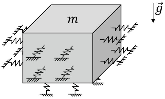
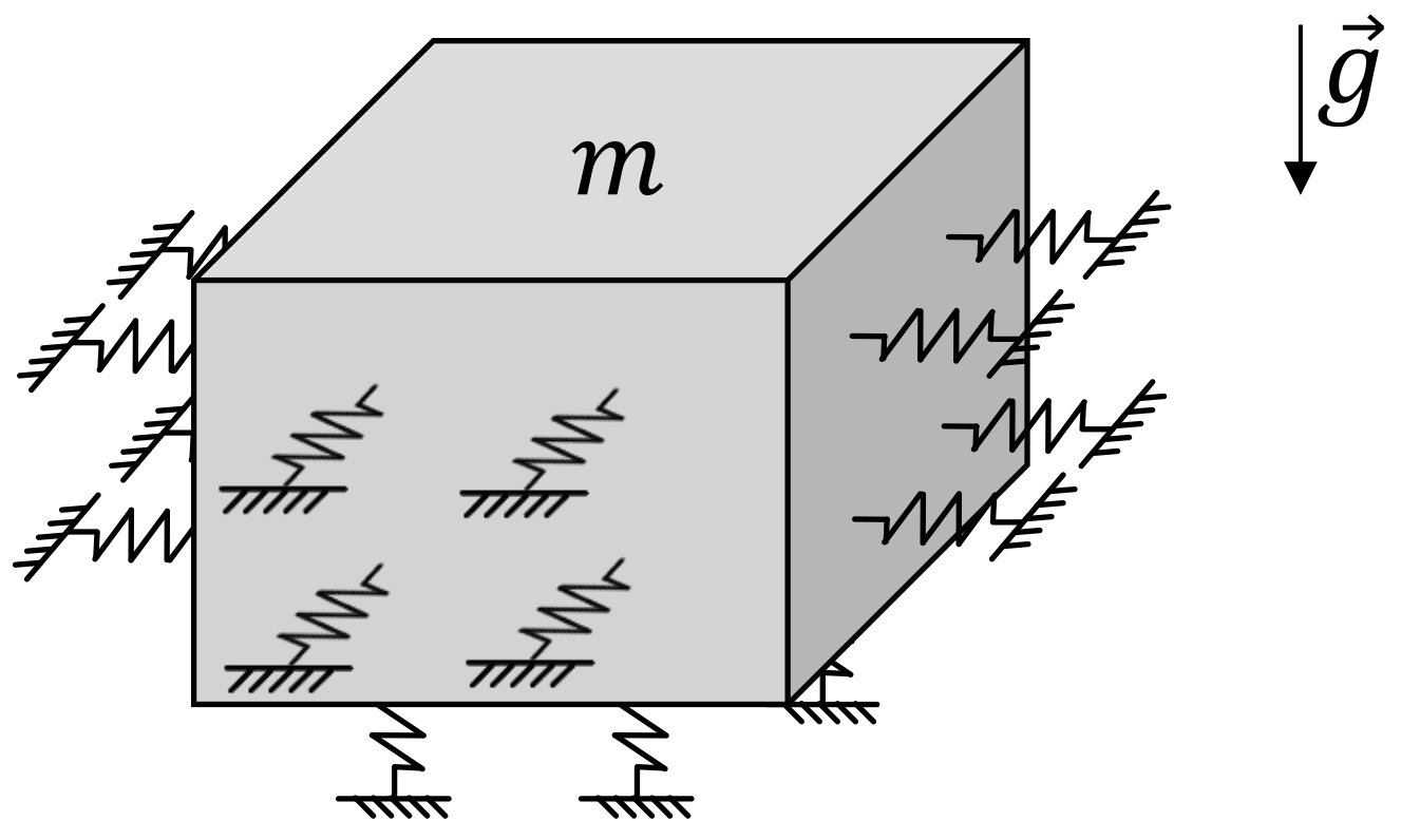
Given this background, the present paper serves as a design study for a 6-DoF QZS system that is aimed at broad-frequency-range vibration isolation and avoids the use of conventional joints. The novel system combines a one-piece type QZS design with a unique elastic bedding approach, utilizing a large number of small helical compression springs with very high internal natural frequencies, as illustrated in Figure 1. The springs are directly mounted to the frame and the moving body using fixed connections rather than conventional joints to effectively prevent particle abrasion. This design approach is based on a 3-DoF QZS system that has been proposed before by the authors of the current paper and achieves vibration isolation in all translational directions [15]. Compared to a traditional linear vibration isolator, it could be shown that the natural frequencies of the overall system can be significantly reduced by a factor of more than five while maintaining the same load capacity. The present paper aims to extend this broad-frequency-range vibration isolation method from the 3-DoF to a 6-DoF system, achieving QZS characteristics in all translational and rotational directions in space.
Figure 1.
Vibration isolation system with QZS design and elastic bedding for broad-frequency-range isolation in three translational DoF for a body with mass m subjected to gravitational acceleration g, based on [15].
The design methodology presented in this paper is based on a two-stage process: First, the optimal system configuration together with suitable spring parameters is determined for the 3-DoF system through numerical optimization. Practical requirements like high natural frequencies of the springs to prevent internal resonances as well as lateral spring stiffness effects resulting from the fixed spring attachments are considered. Then, the optimized system design is adapted for 6-DoF vibration isolation through a specific spring arrangement. In contrast to the 3-DoF system, the translational and rotational motions are inherently coupled and therefore depend on one another. The main design challenge arises from the mutual influence of the spring positions on the natural dynamics of the system. This influence is analyzed based on an analytical stiffness formulation. This enables systematic tuning of the resulting stiffness characteristics to achieve a stable system configuration exhibiting a significant reduction of the natural frequencies, close to a desired target frequency, compared to a non-QZS design in all 6-DoF.
The overall objective is to demonstrate the feasibility of such a 6-DoF QZS vibration isolation system layout for structures on the order of several meters in size and with masses of multiple tons, while satisfying practical design requirements for the spring elements.
2. Methodology
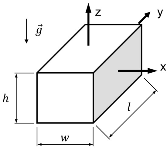
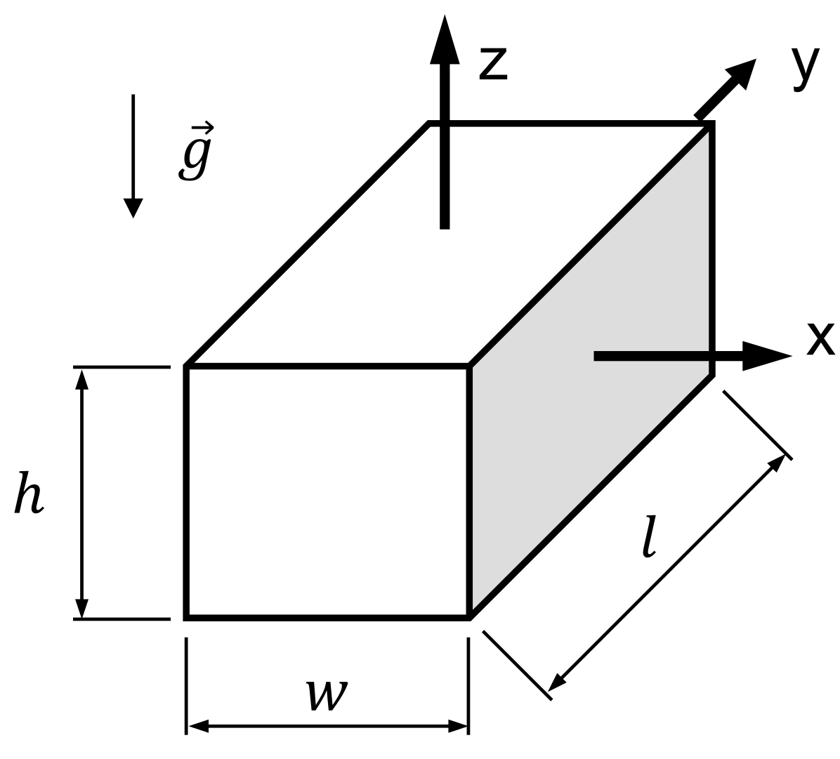
The system to be isolated is simplified in the following as a cuboidal body with all six spacial DoF as shown in Figure 2. Its dimensions are characterized by the length l, the width w and the height h. A homogeneous mass distribution is assumed, with the mass m and the moments of inertia , and about the principal axes of inertia. The reference coordinate system is positioned in the center of mass in the middle of the body. The system is subjected to gravity with gravitational acceleration in negative z-direction. Representative quantitative values of a system with a high mass of 2500 kg, which will be used in this paper, are given in Table 1. The body is assumed to have different side lengths to account for varying lever arms and moments of inertia in a generic application.
Figure 2.
Cuboidal body with six DoF.
Table 1.
Exemplary parameters of the body to be isolated.
The lower end of the vibration isolation frequency range is defined by a desired natural frequency of the overall system and chosen to be Hz. On the one hand, this value represents a low frequency for vibration isolation in high-mass applications, but on the other hand, it also provides a safety margin to 0 Hz. The latter would imply stiffness values of zero and should be avoided, as this can easily result in instability [19]. The upper end of the frequency range is defined by a desired internal natural frequency of the supporting springs, which is chosen to be above Hz. The system must be designed so that it does not exhibit any resonances within this frequency range .
In this section, the methodology for designing the QZS vibration isolation system with six DoF is presented. The design methodology is divided into two sequential stages:
- In the first stage, the system is simplified to a point-mass system with three translational DoF, which will be referred to as 3-DoF system. Here, only translational motions are considered and all rotational motions are neglected. The goal of this design stage is to identify an optimal system design such that the desired broad-frequency-range vibration isolation is achieved for all translational DoF. This includes finding suitable helical compression springs and determining their number and required precompression in order to achieve the desired QZS properties. The underlying concept and optimization methodology were presented in [15] and will be summarized in Section 2.1. Please refer to [15] for further details.
- In the second design stage, see Section 2.2, the optimized 3-DoF system is extended to the final system design, considering the body now as a geometrically extended body with all six DoF. This system will be referred to as 6-DoF system. The goal of this design stage is to achieve broad-frequency-range vibration isolation in all six DoF. To this end, the results from the 3-DoF systems are further developed, dividing the springs on each surface of the body into separate spring packages. The positioning of the spring packages is then adjusted in order to tune the rotational stiffness of the 6-DoF system. This requires a mathematical formulation to describe and evaluate the natural dynamic behavior of the system, outlined in Section 2.2.1. Furthermore, the stiffness matrix of the system is derived analytically as described in Section 2.2.2, enabling a detailed analysis of the influence of the spring positioning on the system’s natural dynamic behavior.
2.1. 1st Design Stage: 3-DoF System
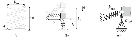
In the 3-DoF QZS system, the point-mass is supported by a number of identical helical compression springs, whose geometry is defined by the wire diameter d, coil diameter , number of windings n and undeflected length , see Figure 3a. They are arranged as shown in Figure 1, with vertical springs on the bottom and horizontal springs on each side of the body, respectively. In the design configuration, the vertical springs are precompressed to a compressed length due to the effect of the weight force, see Figure 3b. The horizontal springs are installed with a compressed length in order to achieve the desired QZS properties.
Figure 3.
Properties and details of the 3-DoF system. (a) Helical compression spring; (b) Precompression of the springs; (c) Substitute model for the lateral stiffness effect.
All springs are directly mounted via fixed connections at their ends, in order to prevent particle abrasion related to relative motion of traditional joints. This boundary condition leads to lateral restoring forces when the springs are deflected laterally. A substitute model as shown in Figure 3c aims to reflect this stiffness effect. Each spring is complemented by an additional virtual spring with stiffness that is positioned perpendicular to the actual spring. While the axial stiffness
of the spring is constant and depends only on the spring parameters [27], the lateral stiffness also depends on the deflection s of the spring and is calculated according to [15,27]
The symbol G in Equation (1) refers to the shear modulus of the spring material.
For the system design given in Figure 1, the overall stiffness of the 3-DoF QZS system in vertical direction can be written as
as derived in [15] based on formulas presented in [28]. This formula consists of several stiffness contributions: The first addend corresponds to the positive stiffness of the vertical springs, i.e., the springs that are oriented in the direction of motion. The second addend is related to the two stiffness effects of the horizontal springs on each side of the body, which are the springs oriented perpendicular to the direction of motion. First, the lateral stiffness of the horizontal springs creates restoring lateral forces when these springs are deflected laterally. Second, the precompression of these springs creates a negative stiffness effect. This effect is caused by the fact that the precompression forces feature a component in the direction and orientation of motion when the body is deflected in vertical direction. As a result, the compression forces promote the deflection of the body. This negative stiffness effect is indicated by the negative sign in Equation (3). Analogously, the overall stiffness of the 3-DoF QZS system in both horizontal directions is
considering that the horizontal springs on two sides of the body are oriented into the direction of motion, while the vertical springs as well as the horizontal springs on the remaining sides are oriented perpendicular to that direction. The symbol refers to the lateral stiffness of the vertical springs. Because vertical and horizontal motions are not coupled in this system design, the natural frequencies and of the 3-DoF QZS system in vertical and horizontal direction, respectively, can be calculated as
The design aims to balance the different positive and negative stiffness contributions such that the natural frequencies and can be reduced without deteriorating the load capacity of the system. This goal is mathematically expressed through an objective function that optimizes the natural frequencies to be as close as possible to the desired value . The design variables to be determined by optimization are the geometrical spring parameters d, , and n, as well as the system parameters , , and . Constraints are employed to consider several practical requirements and restrictions in the spring design. The minimum compressed length of the springs is constrained to ensure that the material strength limit is not exceeded, to prevent the risk of buckling, to avoid mutual contact of the windings and to avoid negative lateral spring stiffness. To achieve broad-frequency vibration isolation and avoid critical high natural frequencies in the isolation system, an additional constraint ensures that the internal natural frequency of the springs is above the desired value . The natural frequency is determined analytically [27], considering longitudinal oscillations of springs, which, according to the system design, are assumed to be fixed on both sides. Please refer to [15] for more details on the constraints utilized in the optimization process.
The procedure to solve the optimization problem is based on a spring catalog with more than 25,000 springs of different, randomly distributed geometry. Their material is assumed to be a stainless steel called Stavax Supreme with shear modulus G = 80,000 N/mm2 and tensile strength = 1500 N/mm2 [15]. For each spring from the catalog, a 3-DoF QZS system is set up and optimized by finding the best system parameters , , and . The underlying single-objective optimization problem is solved with a two-step optimization approach. First, global optimization using a genetic algorithm with 50 individuals is employed to find the neighborhood of the global optimum. Its solution is then used as starting point for a subsequent local optimization using an interior point algorithm in order to converge to that optimum. As the objective function and constraints are only based on analytical computations, the optimization of one 3-DoF QZS system only requires a few seconds on standard computer hardware. The optimization procedure is repeated for each 3-DoF QZS system that is created using the springs from the spring catalog. More information about the optimization procedure can be found in [15].
Applying this methodology to the system investigated in the present paper, the following solution was found. The spring and system parameters and relevant properties can be found in Table 2. This solution was selected from the various optimized 3-DoF QZS systems as it achieves the desired natural frequencies and requires a comparatively low number of springs. Notably, the optimization process selects relatively small springs, i.e., with small wire diameter d and short undeflected length , of which a large number is utilized in the 3-DoF system. This is related to the requirements of broad-frequency vibration isolation, i.e., very low natural frequency of the system and very high natural frequency of the springs. Furthermore, the lateral stiffness should be low in order to obtain low total stiffnesses and , which is achieved by small springs. Due to the small spring dimensions, several hundred vertical springs are required to carry the weight of the body. This also involves a number of precompressed horizontal springs in the same order of magnitude to employ the desired QZS effect. A more in-depth analysis of these relationships is given by the authors of the present paper in [15], where this system design is also called elastic bedding approach.
Table 2.
Spring parameters and resulting system properties of the 3-DoF system with m = 2500 kg, optimized for Hz and Hz.
2.2. 2nd Design Stage: Extension to the 6-DoF System
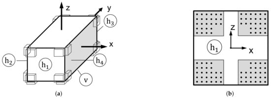
The 6-DoF QZS system is designed to achieve vibration isolation not only for translational but also rotational motions of the body in the desired frequency range. An illustration of the system is shown in Figure 4a. The system adapts the results obtained in the first design stage, i.e., the helical compression springs, their number and their precompression found by the optimization. At the same time, the practical requirements and restrictions in the spring design and the internal natural frequency of the springs are also satisfied in the 6-DoF system.
Figure 4.
Overview for the 6-DoF QZS system with coordinate system in the center of mass and an exemplary positioning of the spring packages. The bottom of the body with vertical springs is denoted with , and the sides with horizontal springs are denoted with . (a) Positioning of the spring packages on the surfaces of the body; (b) Exemplary and oversized illustration of the spring packages.
In a first step, the springs on each surface of the body are divided and arranged in four spring packages. These spring packages are arranged symmetrically to the center of the respective surface, see Figure 4b. Each spring package on a surface should contain the same number of springs to ensure symmetry. Therefore, the total numbers of springs and on each surface, which have been found in the first design stage, are rounded up to values that are integer multiples of four. It should be noted that the increase of vertical springs slightly reduces their precompression, as the weight force of the body is constant. Rounding up the numbers of springs is therefore a conservative approach to avoid exceeding the minimum allowed precompressed length of the springs. The precompression of the horizontal springs is not altered.
For the exemplary system investigated in the present paper, the numbers of springs are changed to and , and the compressed length of the vertical springs is slightly altered to mm. Each vertical spring package on the bottom of the body consists of 107 springs, which are arranged approximately in a pattern. Each horizontal spring package on the sides of the body contains 51 springs arranged approximately in a pattern. Consequently, the dimensions of the spring packages are in the order of , taking into account the spring diameters and d as well as a small gap between the springs to avoid mutual contact. These dimensions are one order of magnitude smaller than the body’s dimensions, unlike what is depicted in the oversized illustration in Figure 4b.
The second step involves the positioning of the spring packages on the surfaces of the body. This changes the effective lever arms of the spring forces about the body’s center of mass. As a result, the rotational stiffness of the complete spring setup and thus the system’s natural frequencies are adjusted. The goal is to achieve natural frequencies in the range of the desired frequency across all six DoF. Therefore, the natural behavior of the system will be analyzed, utilizing the analytically derived stiffness matrix of the 6-DoF system.
2.2.1. Evaluation of the Natural Behavior
The natural behavior of the 6-DoF system is evaluated in terms of its eigenmodes, which are characterized by their mode shapes and natural frequencies. To this end, the eigenvalues and eigenvectors are derived from the eigenvalue problem
with according to the six DoF of the system. The mass matrix
is a diagonal matrix and contains the mass m and the moments of inertia about the principal axes of inertia, considering the geometry and homogeneous mass distribution of the body, cf. Table 1. The matrix corresponds to the stiffness matrix of the system and will be derived analytically in Section 2.2.2.
If the system is stable, its natural frequencies are obtained from the imaginary parts of the conjugate complex eigenvalues according to
These frequencies should be equal or close to the desired natural frequency .
Furthermore, it is desirable that the translational and rotational motions of the body be decoupled from each other as much as possible. This reduces the complexity of the system design, since individual design parameters ideally do not influence several stiffness characteristics and, vice versa, the stiffness characteristics ideally do not depend on several design parameters. Additionally, this increases the interpretability of the results and dependencies. It should be noted that compliance with this requirement is not necessary to achieve the overall vibration isolation, so it is not a primary design objective. Instead, this property is used to analyze the designed system as it provides additional insights into its natural behavior. Mathematically expressed, a perfect decoupling means that the modal matrix
is as close as possible to the identity matrix . This is assessed using the modal assurance criterion (MAC) [29]. According to
the eigenvector is compared with the reference vector , defined as the i-th column of the identity matrix , representing the desired modal behavior [29]. A value of corresponds to a perfect match of the desired mode shape, and values of are considered to indicate a poor fit [29], related to the coupling of translational and rotational motions of the 6-DoF system.
2.2.2. Derivation of the Stiffness Matrix
The stiffness matrix of the 6-DoF QZS system describes the relationship between the displacements of the body in all DoF, summarized in the vector of generalized coordinates
and the restoring equivalent forces and torques, summarized in the vector of generalized forces
Here, x, y and z refer to translational motions of the body along the coordinate axes, and , and refer to rotational motions about these axes, respectively, cf. Figure 2. , and refer to the corresponding equivalent forces acting on the center of mass, and , and refer to the corresponding equivalent torques acting about the center of mass. The stiffness matrix is obtained from the partial derivatives and, in the design configuration at static equilibrium, is given by
This stiffness matrix is symmetrical and consists of the components on its main diagonal and the coupling terms and , which couple translational and rotational motions about the x- and y-axis. Due to the symmetry of the system, cf. Figure 4a, all other coupling terms are equal to zero. For example, an infinitesimal rotation about the z-axis only causes an infinitesimal torque , represented by the stiffness component , but does not cause any other equivalent forces or torques on the center of mass.
In the following, the stiffness matrix will be derived analytically. To reduce the model complexity and simplify the design process, all individual springs in each spring package are assumed to be located in the middle of the spring package. This is in contradistinction to the actual system design in Figure 4. However, this simplification does not affect the equivalent forces resulting from translational motions of the body, as the derived equations will show. The response to rotational motions and the equivalent torques are slightly affected, but several arguments support the validity of this assumption. First, the dimension of the spring packages (unlike shown in Figure 4b) is relatively small compared to the dimensions of the overall system. Given that the spring packages in the final design will be located close to the edges of the body, the effective lever arms, i.e., the distance between each spring attachment position and the body’s center of mass, are affected to a relatively small extent. In addition, the changes of the lever arms partially cancel each other out, since some springs are located slightly closer and others slightly farther away from the body’s center of mass. Second, only small displacements are expected, allowing rotational motion about the center of gravity to be approximated by a superposition of translational displacements of the spring packages. Although a single equivalent spring located at the geometric center cannot generate a restoring torque when the faces of the spring package are inclined, the symmetric arrangement and combined action of multiple spring packages over a surface area can produce such restoring torques. These assumptions were validated by comparing multi-body models that include all individual springs at their respective position with models in which the springs are located in the middle of their respective spring package.
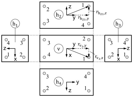
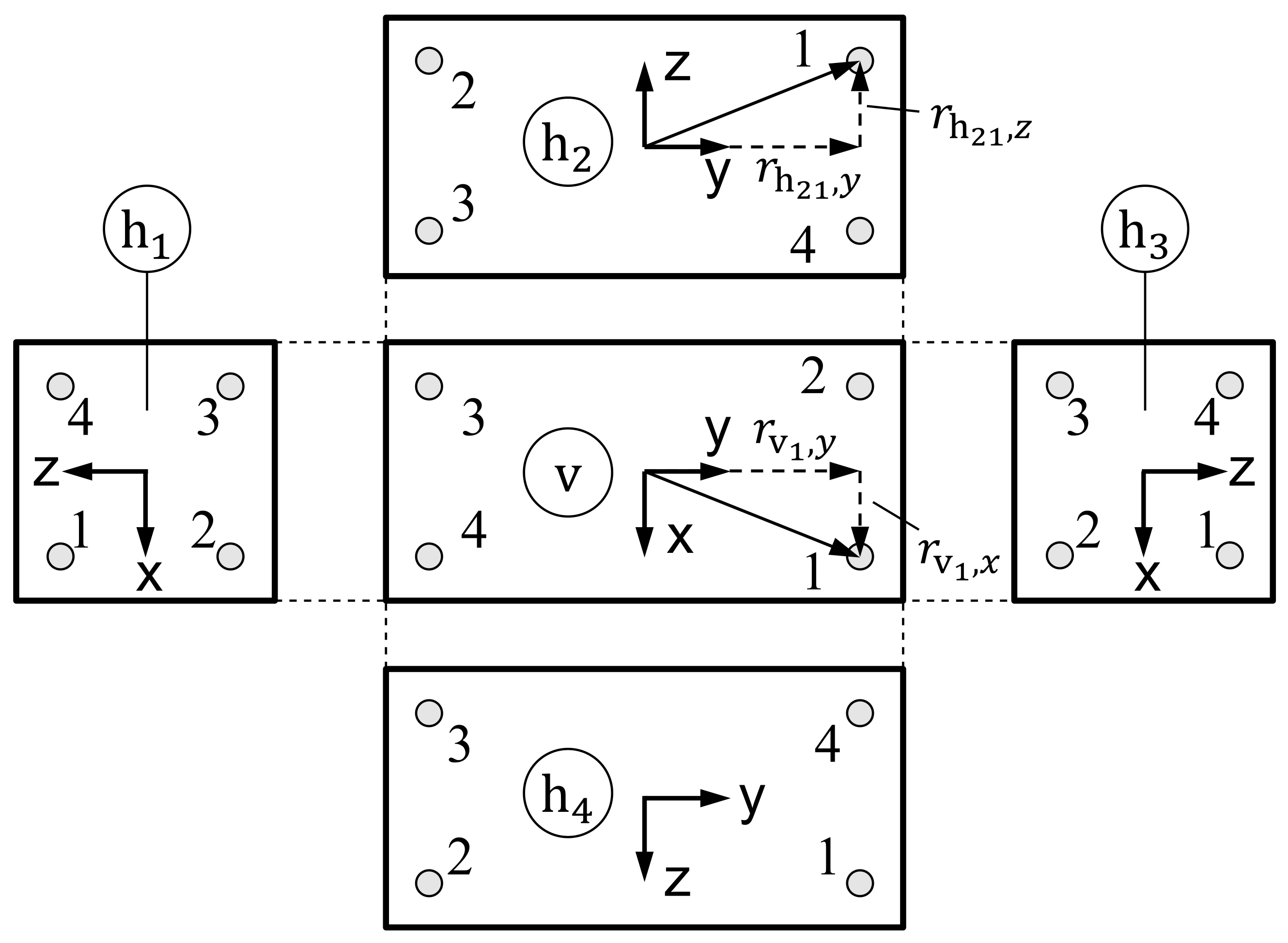
Figure 5 shows the numbering of the body surfaces and the respective spring packages used in the following equations, cf. the system design illustrated in Figure 4a. The vertical spring packages on the bottom side will be denoted with index and numbered from 1 to 4. For example, the position in x- and y-direction of spring package 1 on this surface is denoted with and , respectively. The horizontal spring packages on the respective surfaces are denoted with indices to and numbered from 1 to 4. Consequently, the position in y- and z-direction of spring package 1 on surface is denoted with and .
Figure 5.
Numbering of the body surfaces and the respective spring packages with springs in vertical () and horizontal () direction.
Due to the symmetry of the system, only the design parameters , , , , and are necessary to describe the positions of all spring packages. Using these parameters, the positions of the vertical spring packages can be expressed as
Please note that the position in z-direction is fixed to because the vertical spring packages are placed on the bottom of the body. The positions of the horizontal springs on surfaces and are
and on surface and
Here, the vertical position of the horizontal springs in the top and bottom spring packages is independently defined by and , respectively.
Furthermore, the vertical and horizontal springs are precompressed in order to achieve the desired QZS effect, resulting in precompression forces and acting on the body as
with positive values of the forces in coordinate direction, as per definition.
In the following, the components of the stiffness matrix will be derived, using the normalized lengths
of the horizontal and vertical springs as more compact notation.
The first three components on the main diagonal of the stiffness matrix, , and , describe the stiffnesses in all three translational directions. They are derived similar to the stiffnesses and in the 3-DoF system. Thus, the stiffness in vertical z-direction is
The first addend describes the positive stiffness effect of the vertical springs. The second addend describes the stiffness effects of all horizontal springs, consisting of their positive lateral stiffness and their negative stiffness effect due to precompression, indicated by the negative sign. This equation is similar to the total stiffness of the 3-DoF QZS system, cf. Equation (3). Analogous, the stiffness in x-direction is
It consists of the positive stiffness of all springs oriented in the direction of motion, i.e., the horizontal springs on surface and , as well as the positive lateral stiffness and the negative stiffness effect of all springs oriented perpendicular to that direction, i.e., the vertical springs as well as the horizontal springs on surface and . Likewise, the stiffness in y-direction is
The stiffness components , and describe the rotational stiffnesses, i.e., the equivalent torques resulting from rotations of the body about its center of mass. The rotational stiffness in z-direction is
This equation can be interpreted as follows: When the body rotates about the z-axis, the vertical springs are translationally deflected in their lateral direction, causing restoring forces due to their lateral stiffness but also supporting forces due to their negative stiffness effect. The position of the vertical springs on the surface is given by and . The corresponding lever arm creates an equivalent torque about the center of mass and a stiffness effect that takes into account the square of that lever arm . The horizontal springs on surface and are translationally deflected both in their axial and lateral direction. Their axial deflection results in a positive stiffness effect with the square of the lever arm , and their lateral deflection results in a stiffness effect analogous to the vertical springs, but with the square of the lever arm . The last addend related to the horizontal springs on surface and considers the change of the lever arm of the compression forces due to the body’s rotation and the corresponding stiffness effect. The effect of the horizontal springs on surface and can be interpreted analogously to those on surface and .
By analogy, the rotational stiffness about the x-axis is
taking into account that, in this case, the horizontal springs on surface and are the ones that are deflected only in their lateral direction and the vertical springs as well as the horizontal springs on surface and are the ones that are deflected both in their axial and lateral direction. Likewise, the rotational stiffness about the y-axis is obtained as
The stiffness components and describe the coupling of the translational and rotational motions about the x- and y-axis, which results from the asymmetry of the system’s layout, i.e., the center of stiffness is in general not located in the body’s center of mass. The stiffness component is
and can be read as follows: When the body is translationally displaced into y-direction, the horizontal springs on surface and are deflected in their axial direction, causing restoring forces that create a torque about the body’s center of mass. Depending on their position , this torque acts in mathematically positive or negative direction. The vertical springs and the horizontal springs on surface and are deflected in their lateral direction, resulting in restoring forces due to their lateral stiffness as well as supporting forces due to their negative stiffness effect, which act with the lever arms and , respectively. The stiffness component can be obtained with analogous considerations and is
As can be seen from the equations, the translational stiffness components , and do not depend on the positioning of the spring packages. In contrast, the rotational stiffness components , and , and the coupling components and depend on the spring positioning. Thus, repositioning of the spring packages changes the effective lever arms and therefore the stiffness effect, which will be exploited to achieve the desired vibration isolation properties. It should also be noted that the coupling components only depend on the positioning of the horizontal spring packages in vertical z-direction and can be eliminated by proper choice.
The analytical stiffness model was validated by comparing it with the results of a numerical linearization. For this purpose, the equivalent forces and torques in Equation (12) were set up for an example system in its static equilibrium position, and the corresponding differential quotients were calculated. The model was further validated through comparison with a multibody dynamics model implemented in an in-house multibody simulation environment.
3. Sensitivity Analysis of the Spring Package Positioning
The overall system design aims to achieve natural frequencies for all translational and rotational motions that are as close as possible to the desired value of Hz. The first stage of the design methodology aims to satisfy this condition for the 3-DoF system in all translational directions as demonstrated in Section 2.1. This is reflected in the determination of the first three components on the main diagonal of the stiffness matrix , see Equation (13). To ensure that these properties are maintained in the subsequent design stage, the spring and system parameters established in this first design stage, see Section 2.1, are carried over to the second design stage.
The second design stage, see Section 2.2, accounts for the rotational motions of the body, considering the body now as an extended body instead of a point mass. Consequently, five additional components in the stiffness matrix need to be designed appropriately. The dependencies of these components on the design variables, primarily on the spring positioning, have been derived analytically in Section 2.2. The positioning of the spring packages influences these stiffness components by altering the lever arm between the spring package and the center of mass.
Changes in the positioning of the spring packages do not only influence one but several components of the stiffness matrix at the same time. Due to this mutual dependency, optimizing individual stiffness components without affecting others presents challenges. Thus, direct determination of an optimal system configuration is not feasible. To investigate these effects, the influence of the spring package positioning on the components of the stiffness matrix is analyzed by means of a sensitivity analysis. To this end, a step-by-step analysis is conducted to examine the potential influences. The results should be understood as qualitative information illustrating the dependencies of various parameters on the stiffness matrix components.
The following analysis examines the sensitivities of the stiffness matrix components with respect to the positioning of the individual spring packages, starting with all spring packages placed at the corners of the body. Unless otherwise stated, the spring packages on each surface are moved symmetrically with respect to the center and the outer edges of that surface. Assuming that the system is symmetrically arranged on opposite sides results in three independent surfaces where spring packages can be positioned in two independent ways, respectively. This symmetrical arrangement is necessary to preserve both the translational stiffness components and the structure of the stiffness matrix.
3.1. Positioning of the Vertical Spring Packages
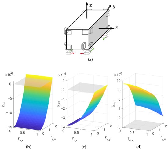
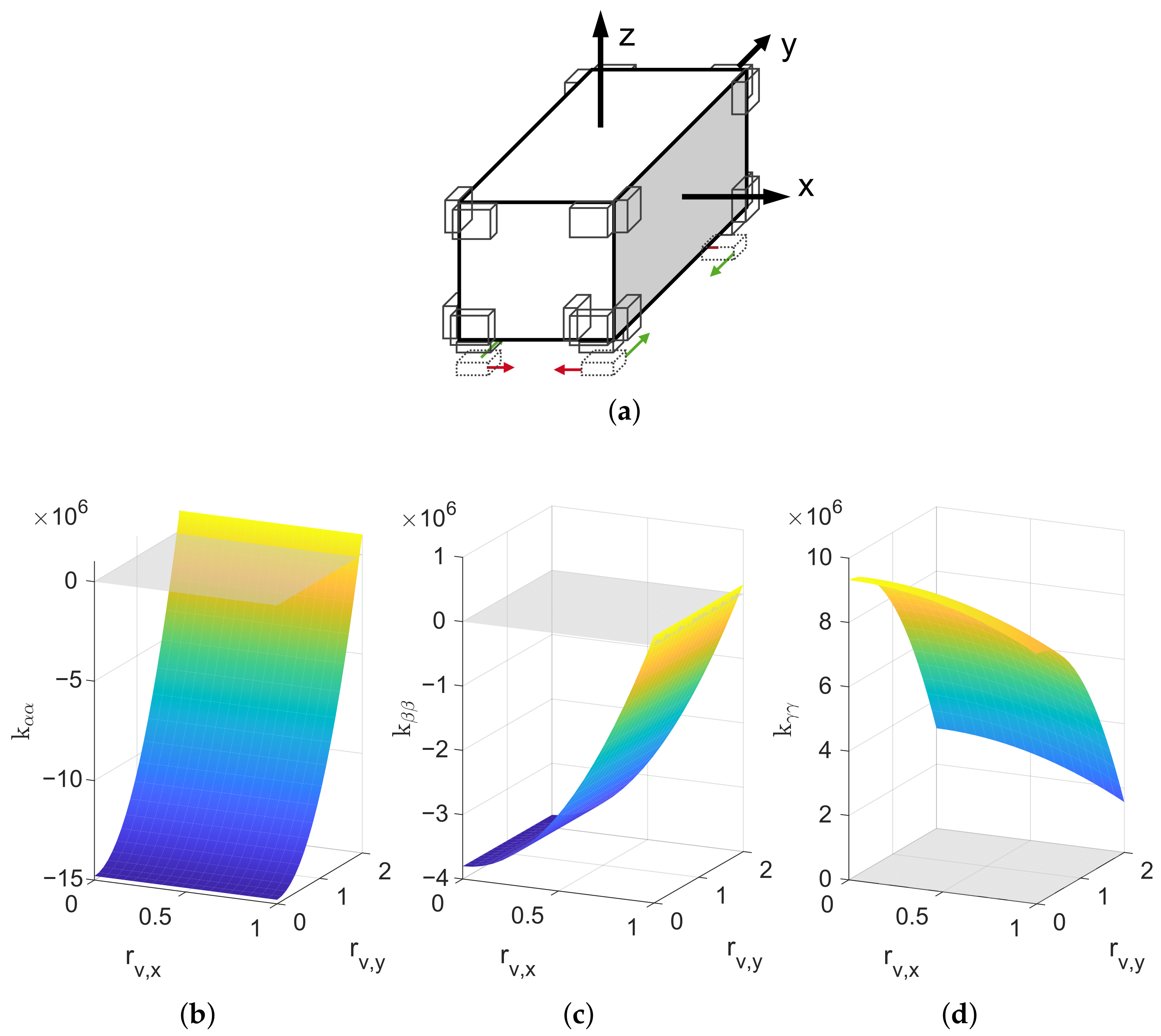
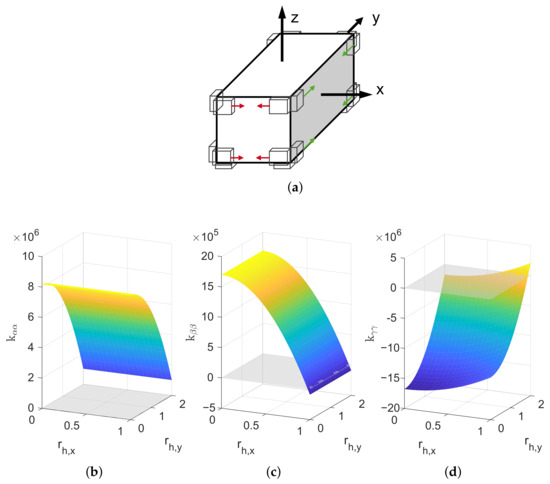
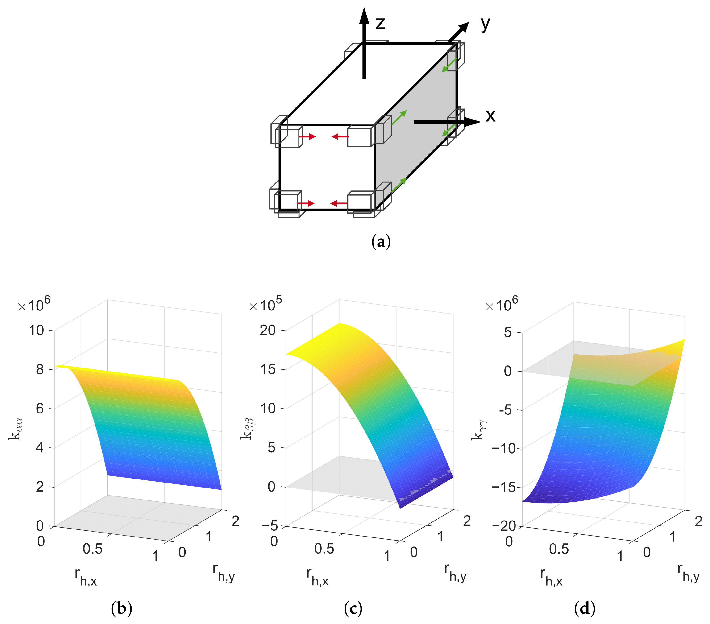
First, the positioning of the vertical spring packages located on the bottom of the body is examined. The correlation between the positions and with regards to the stiffness components , and is presented in Figure 6. The positioning of the spring packages was varied in the ranges and , see Figure 6a, in accordance to the body’s dimensions. Figure 6b–d show the resulting stiffness values. Furthermore, the zero-stiffness level with is visualized to indicate target areas above this plane, as QZS properties with slightly positive stiffness values must be achieved to prevent unstable configurations. The dependence of and on the spring position shows that positioning the spring packages closer to the outer edges of the body leads to higher stiffness, because the lever arms around the center of mass increase. To achieve positive stiffness, the spring packages have to be positioned very close to the edges of the body. As expected, both and are primarily influenced by one variable among two varied parameters, see Figure 6b,c. In contrast, positioning the spring packages closer to the outer edges of the body decreases the stiffness , as illustrated in Figure 6d. This can be explained as the rotation about the z-axis leads to a lateral deflection of the vertical springs. Therefore, the springs exhibit negative stiffness due to their precompression, cf. Equation (22), as a component of the spring force acts in the same direction as the deflection. The higher the distance of the springs to the center of the surface, the higher are the lateral deflection and the lever arm of the precompression force, and thus the negative stiffness contribution. Correspondingly, increased values for the stiffness component are achieved by positioning the spring packages closer to the surface center. Due to the greater length of the cubic body in y-direction, the parameter can be varied within a wider range than , resulting in a more pronounced effect on this stiffness.
Figure 6.
Influence of the positioning of the vertical spring packages in horizontal direction, represented by and , on the stiffness matrix components. The stiffness is given in , and the position is shown in . (a) Variation of the spring package position; (b) Influence on ; (c) Influence on ; (d) Influence on .
3.2. Positioning of the Horizontal Spring Packages in Horizontal Direction
The influence of the positioning of the horizontal spring packages in horizontal direction on the stiffness components , and is shown in Figure 7. Positions were investigated for ranges defined by and , see Figure 7a. A behavior similar to the positioning of the vertical spring packages is observed. Since rotations of the body about the x- and y-axes primarily induce lateral deflections of the horizontal springs, the resulting components of the spring forces amplify the motion via negative stiffness contributions. Consequently, positioning the packages further toward the edges increases the lever arms, which reduces the values of and . The stiffness component has only a positive near-zero value, if the spring packages are placed very close to the outer edges. Due to the larger lever arm, the influence of on is significantly greater than that exhibited through parameter , see Figure 7d.
Figure 7.
Influence of the horizontal positioning of the side spring packages, represented by and , on the stiffness matrix components. The stiffness is given in , and the position is shown in . (a) Variation of the spring package position; (b) Influence on ; (c) Influence on ; (d) Influence on .
3.3. Positioning of the Horizontal Spring Packages in Vertical Direction
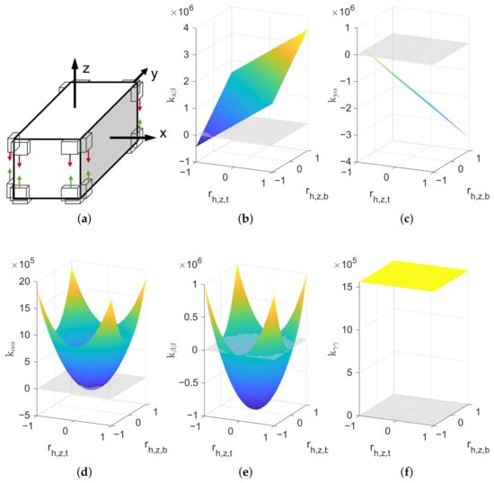
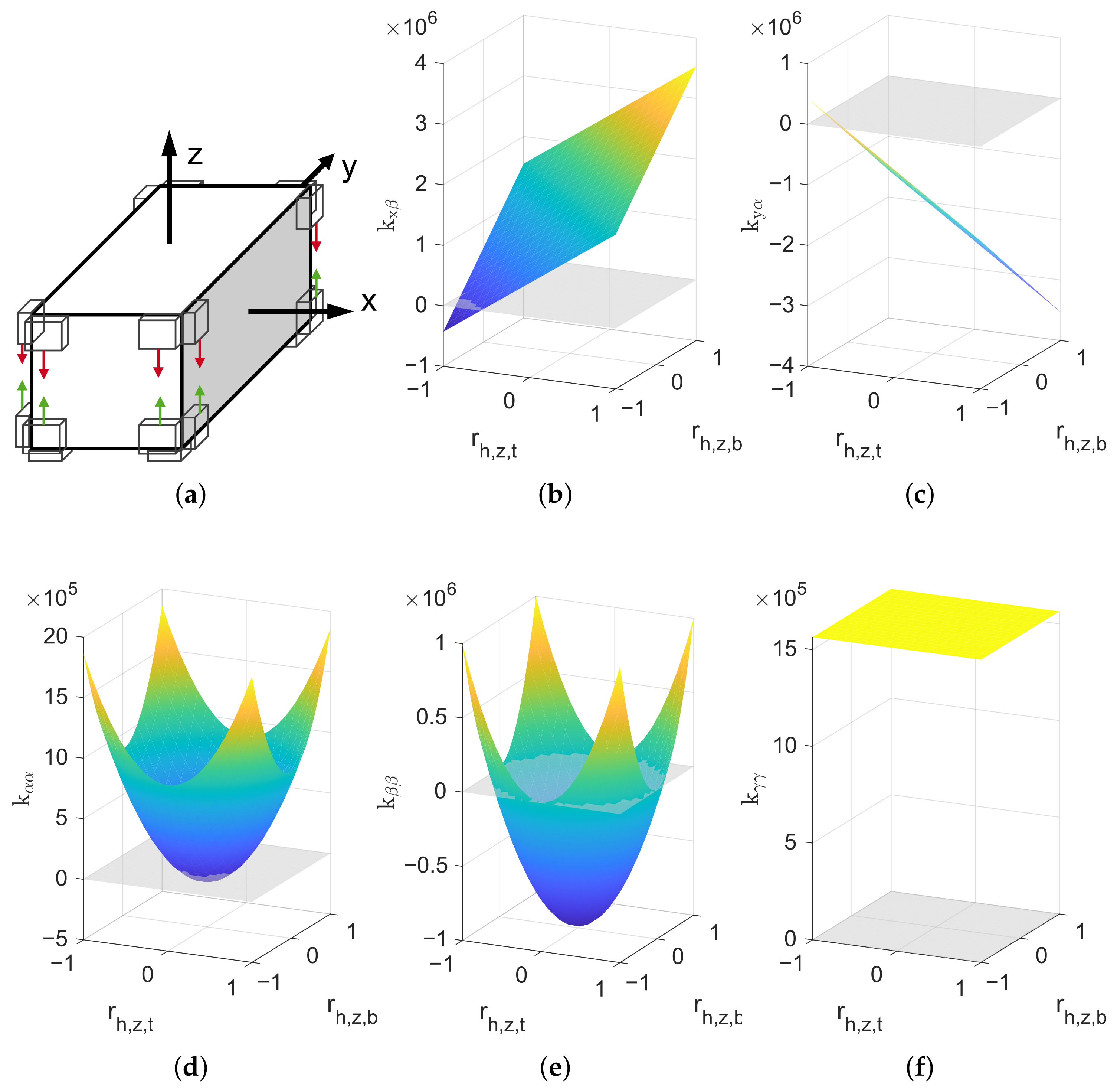
The vertical positioning of the horizontal spring packages demonstrates the highest influence on the components of the stiffness matrix. The parameter variation of and is investigated within the interval of , see Figure 8a. This allows analysis regarding configurations where both top and bottom spring packages are located at the same position on their respective body surface. The influence on the stiffness components and is visualized in Figure 8d,e. In contrast to the previous analyses, the stiffness values now depend equally on both parameters, resulting in a circular paraboloid shape. The parameter variation has no influence on the stiffness component , see Figure 8f. The vertical positioning of the horizontal spring affects not only the main-diagonal components of the stiffness matrix, but also the off-diagonal components and . To achieve mostly decoupled motions across all six DoF and therefore all translational and rotational directions, values close to zero for these off-diagonal terms are desirable. The analysis shows that the optimal configuration is achieved when both the top and bottom spring packages are placed below the center of mass, resulting in an asymmetrical arrangement, see Figure 8b,c.
Figure 8.
Influence of the vertical positioning of the side spring packages, represented by and , on the stiffness matrix components. The stiffness is given in (for and ) and (for , and ), and the position is shown in . (a) Variation of the spring package position; (b) Influence on ; (c) Influence on ; (d) Influence on ; (e) Influence on ; (f) Influence on .
4. Results
In the following section, the natural behavior of the proposed system is analyzed and evaluated with respect to the natural frequencies in all six degrees of freedom as well as compliance with the MAC criterion defined in Equation (10).
To provide a reference, a simple conventional vibration isolation system is introduced. The goal of this reference system is primarily to assess the effectiveness of the QZS design approach, rather than to provide an alternative with respect to aspects such as mechanical complexity. For the comparison, a body with the same geometrical dimensions and mass is chosen. For comparability, the number and properties of the springs attached to each side of the body are identical to those of the optimized system. The vertical spring packages remain compressed solely by the gravitational load of the supported body, providing a QZS effect in the orthogonal directions. To eliminate any further QZS effect, the horizontal spring packages are neither precompressed nor inclined in the design position. To further demonstrate the effects of the presented method, the spring package positions are not refined in any way. In this configuration, the spring packages are located at the outer edges of each supporting surface, as summarized in Table 3.
Table 3.
Positions of the spring packages for the conventional reference system with body parameters given in Table 1.
The resulting modal behavior of the reference system, expressed in terms of the natural frequencies and the compliance of the modal matrix with the identity matrix , is presented in Table 4. Although not all MAC values are close to one, a good separation of the individual motions can still be observed, with only minor coupling between translational and rotational oscillations. Furthermore, all natural frequencies are significantly greater than zero, confirming that the system is dynamically stable. The natural frequencies for the translational DoF () are in the range of . The comparatively low natural frequencies in the horizontal directions are attributed to the negative stiffness effect introduced by the vertical springs, which are precompressed by the gravitational load of the body. The rotational modes () exhibit even higher natural frequencies, with . The variance within this range is primarily caused by the different lever arms of the spring packages and the different moments of inertia associated with the respective rotational axes.
Table 4.
Natural dynamic behavior of the conventional reference system, including the natural frequencies and corresponding MAC values of all eigenmodes.
To demonstrate the feasibility and effectiveness of a 6-DoF QZS vibration isolation layout, a spring package configuration was determined based on the analysis presented in Section 3. The selected configuration exhibits low values of the coupling stiffness terms and , while the diagonal stiffness components , , and yield natural frequencies associated with the rotational degrees of freedom that are close to the target value of Hz. The configuration is shown in Table 5. The vertical spring packages are positioned at the outer edges of the body. The horizontal spring packages are located close to the outer edges in the horizontal direction and below the center of mass in the vertical direction, thereby largely decoupling the translational and rotational motions.
Table 5.
Positions of the spring packages for the QZS system, designed to achieve natural frequencies of Hz in all six degrees of freedom, with body parameters given in Table 1.
This parameter choice leads to the stiffness matrix
The components , , and are similar to the stiffness values and of the 3-DoF system due to the first stage of the design methodology, see Table 2. The values of the off-diagonal terms and are one order of magnitude smaller than the main-diagonal terms, and the components , , and are adjusted to achieve the desired frequency Hz of the body’s rotational motions.
Finally, the evaluation of the system’s natural behavior is summarized in Table 6. The table presents the natural frequencies along with the corresponding eigenvectors. In addition, the decoupling of translational and rotational motions of the body is assessed using the MAC as described in Section 2.2.1. To compare the magnitudes of translational and rotational motions, the translational displacements in the eigenvectors are expressed in the unit m according to the dimensions of the body, in order to keep them in the same order of magnitude.
Table 6.
Natural dynamic behavior of the QZS system, including the natural frequencies, eigenvectors, and corresponding MAC values of all eigenmodes.
The results show that all natural frequencies of the investigated body with a mass of m = 2500 kg are close to the desired frequency of Hz. In comparison to the conventional reference system, cf. Table 4, a reduction of the natural frequency of approximately 70% and of the rotational modes of approximately 80% was achieved. None of the eigenmodes exhibits unstable behavior that would cause the system to diverge from its equilibrium position after a slight disturbance. The objective of identifying a stable system configuration capable of significantly reducing the natural frequencies toward a desired frequency was thus achieved. It should be noted that, with this design, additional requirements are also fulfilled due to the first stage of the design methodology: the material strength limit of the springs is not exceeded, buckling is prevented, mutual contact of the spring windings is avoided, and all internal natural frequencies of the springs satisfy the requirement Hz.
Additionally, the resulting modal matrix closely matches the identity matrix, with only a few non-ideal entries. However, this does not compromise the goal of a significant stiffness reduction for improved vibration isolation, but instead indicates coupled translational and rotational motions, most visibly present in eigenmodes 1 and 5.
5. Discussion and Limitations
Despite these promising results, several limitations remain. The current design does not yet include an explicit optimization of the spring package positioning, which may be relevant for achieving a global optimum with respect to matching the desired frequency, as already implemented in the first design stage proposed in [15]. The proof of feasibility for designing a stable vibration isolation system with frequencies close to the desired target frequency has already been demonstrated within this work.
Beyond the scope of this study, but prior to practical implementation, is the investigation of stiffness curves and the behavior of the system under different excitation modes and with respect to assembly tolerances. This could be extended to the determination of frequency–transmissibility behavior. Also of interest in the context of further dynamic investigations is the influence of damping on the overall system behavior.
One important aspect for future investigation is the manufacturability of the spring packages. The spring design itself requires custom spring production, which is technologically possible but not optimal. The design of the individual spring packages involves the precise assembly of approximately springs between two surfaces. The spring packages could subsequently be installed as closed modules connecting the body and the frame.
6. Summary
This work introduces a systematic design methodology for multi-directional vibration isolation systems for high masses in all six degrees of freedom using a QZS-based spring support structure. The design is based on an elastic bedding concept using helical compression springs and exploits the QZS effect under practical and application-driven constraints typical for high-precision manufacturing.
The design methodology consists of a two-stage process. In the first stage, the QZS system is designed for vibration isolation in all translational directions. Suitable springs are selected from a spring catalog, and the system’s parameters, i.e., the number of springs and their precompression, are optimized in order to exploit the QZS behavior in all three translational directions. Constraints such as material strength limit, spring buckling and mutual contact of windings are taken into account. Furthermore, the internal natural frequency of the springs has to exceed a certain limit in order to prevent high-frequency resonances in the vibration isolation system.
In the second stage, the system is extended for vibration isolation in all six DoF. To this end, the springs on each surface of the body are subdivided into spring packages, and their positions on the surfaces are adjusted in order to achieve low natural frequencies for all six DoF. Since direct determination of the system design is not feasible due to the complex interdependencies, the mutual influence of the spring package positioning on the system’s natural dynamic behavior was systematically investigated. For this purpose, the stiffness matrix of the entire system was derived analytically. Based on a subsequent sensitivity analysis of the different components of the stiffness matrix with respect to the spring package positioning, a feasible design was developed.
The proposed approach yields a vibration isolation system whose spring elements have internal natural frequencies above 1000 Hz and achieves a significant reduction of natural frequencies toward a target frequency of 2 Hz for a supported mass of 2500 kg. In comparison to a simplified reference system without QZS effect, reductions in natural frequencies in both translational and rotational directions of up to 80% were achieved, while maintaining the same load capacity. The results demonstrate the feasibility of applying QZS-based vibration isolation concepts to large-scale multi-DoF systems under realistic design constraints.
Author Contributions
Conceptualization, J.B., J.-L.A., M.N. and B.C.; methodology, J.B. and J.-L.A.; software, J.B. and J.-L.A.; validation, J.B. and J.-L.A.; writing—original draft preparation, J.B. and J.-L.A.; writing—review and editing, J.B., J.-L.A., M.N. and B.C.; supervision, J.B., J.-L.A., M.N. and B.C.; All authors have read and agreed to the published version of the manuscript.
Funding
This research received no external funding.
Data Availability Statement
The data presented in this study are available on request from the corresponding author.
Conflicts of Interest
Author Marwène Nefzi was employed by the company Carl Zeiss SMT GmbH. The remaining authors declare that the research was conducted in the absence of any commercial or financial relationships that could be construed as a potential conflict of interest.
Abbreviations
The following abbreviations are used in this manuscript:
| DoF | Degree of freedom |
| MAC | Modal assurance criterion |
| QZS | Quasi-zero-stiffness |
References
- Ma, Z.; Zhou, R.; Yang, Q. Recent Advances in Quasi-Zero Stiffness Vibration Isolation Systems: An Overview and Future Possibilities. Machines 2022, 10, 813. [Google Scholar] [CrossRef] [Scilit]
- Li, T.; Guo, S.; Lin, Z.; Zhao, B.; Tan, J.; Yu, C. Ultra-low frequency pneumatic–mechanical–electrical active vibration isolator considering internal resonance. Int. J. Mech. Sci. 2026, 322, 111680. [Google Scholar] [CrossRef] [Scilit]
- Ibrahim, R. Recent advances in nonlinear passive vibration isolators. J. Sound Vib. 2008, 314, 371–452. [Google Scholar] [CrossRef] [Scilit]
- Li, H.; Li, Y.; Li, J. Negative stiffness devices for vibration isolation applications: A review. Adv. Struct. Eng. 2020, 23, 1739–1755. [Google Scholar] [CrossRef] [Scilit]
- Jiao, G.; Xu, G.; Wang, S. Quasi-zero-stiffness vibration isolation: A comprehensive review of design principles and engineering applications. Int. J. Non-Linear Mech. 2026, 188, 105388. [Google Scholar] [CrossRef] [Scilit]
- Chai, Y.; Jing, X. Low-frequency multi-direction vibration isolation via a new arrangement of the X-shaped linkage mechanism. Nonlinear Dyn. 2022, 109, 2383–2421. [Google Scholar] [CrossRef] [Scilit]
- Chai, Y.; Jing, X.; Guo, Y. A compact X-shaped mechanism based 3-DOF anti-vibration unit with enhanced tunable QZS property. Mech. Syst. Signal Process. 2022, 168, 108651. [Google Scholar] [CrossRef] [Scilit]
- Wang, J.; Yao, G. A3-DOF frog-inspired quasi-zero stiffness isolator and its vibration control performance. Aerosp. Sci. Technol. 2024, 149, 109163. [Google Scholar] [CrossRef] [Scilit]
- Wang, J.; Yao, G. Multi-directional vibration isolation performances of a scissor-like structure with nonlinear hybrid spring stiffness. Nonlinear Dyn. 2024, 112, 8871–8888. [Google Scholar] [CrossRef] [Scilit]
- Luo, C.; Zhu, Z.; Guo, Y.; Wang, J.; Jing, X. Multi-direction vibration isolation with tunable QZS performance via novel X-mechanism design. Commun. Nonlinear Sci. Numer. Simul. 2024, 137, 108140. [Google Scholar] [CrossRef] [Scilit]
- Hu, X.; Jing, X. A compact 3-DoF nonlinearity-tuning motif for multi-direction vibration isolation. Mech. Syst. Signal Process. 2026, 254, 114343. [Google Scholar] [CrossRef] [Scilit]
- Hu, X.; Zhou, C. A stable horizontal 3-DOF vibration isolation system with adjustable stiffness: Theoretical analysis and experiment. Mech. Syst. Signal Process. 2025, 230, 112631. [Google Scholar] [CrossRef] [Scilit]
- Zhou, C.; Song, Y.; Sun, H.; Hu, X.; Yang, L.; Pu, H.; Liu, C. Design and experiment of an Integrate 3-DoF adjustable QZS vibration isolation system with High-Order stability. Mech. Syst. Signal Process. 2025, 228, 112483. [Google Scholar] [CrossRef] [Scilit]
- Zhu, G.; Cao, Q.; Chen, Y. An archetypal zero- or quasi-zero-stiffness model with three degrees of freedom based upon an inverse method. Nonlinear Dyn. 2023, 111, 2029–2057. [Google Scholar] [CrossRef] [Scilit]
- Archut, J.; Bolk, J.; Nefzi, M.; Corves, B. Broad Frequency Range Decoupling Based on Elastic Bedding and Zero Stiffness Design. In Proceedings of the New Trends in Mechanism and Machine Science. EuCoMeS 2024; Rosati, G., Gasparetto, A., Ceccarelli, M., Eds.; Mechanisms and Machine Science; Springer: Cham, Switzerland, 2024; Volume 165. [Google Scholar] [CrossRef] [Scilit]
- Liu, T.; Li, A. An innovative three-dimensional QZS vibration isolator and multi-stage vibration isolation platform design. Mech. Syst. Signal Process. 2025, 237, 113070. [Google Scholar] [CrossRef] [Scilit]
- Chen, R.; Li, X.; Tian, J.; Yang, Z.; Xu, J. On the displacement transferability of variable stiffness multi-directional low frequency vibration isolation joint. Appl. Math. Model. 2022, 112, 690–707. [Google Scholar] [CrossRef] [Scilit]
- Zhou, C.; Sui, G.; Shan, X.; Wu, W. A spatially mechanical-decoupled three-DOF quasi-zero-stiffness isolator integrating flexible curved beams. Int. J. Mech. Sci. 2026, 312, 111160. [Google Scholar] [CrossRef] [Scilit]
- Liu, C.; Zhang, W.; Yu, K.; Liu, T.; Zheng, Y. Quasi-zero-stiffness vibration isolation: Designs, improvements and applications. Eng. Struct. 2024, 301, 117282. [Google Scholar] [CrossRef] [Scilit]
- Li, B.-y.; Shuai, C.-g.; Ma, J.-g. Rolling stability analysis of high-static-low-dynamic stiffness floating raft vibration isolation systems. J. Vib. Control 2023, 29, 5161–5169. [Google Scholar] [CrossRef] [Scilit]
- Li, B.-y.; Shuai, C.-g.; Ma, J.-g. Mechanical characteristics analysis of high dimensional vibration isolation systems based on high-static-low-dynamic stiffness technology. Sci. Rep. 2024, 14, 8195. [Google Scholar] [CrossRef] [Scilit] [PubMed]
- Shen, B.; Chen, Q.; Song, T.; He, W. Design and experiments of a six-degree-of-freedom quasi-zero-stiffness passive vibration isolator based on compressed springs and Euler buckled struts. Nonlinear Dyn. 2025, 113, 12641–12660. [Google Scholar] [CrossRef] [Scilit]
- Yang, T.; Cao, Q. Modeling and analysis of a novel multi-directional micro-vibration isolator with spring suspension struts. Arch. Appl. Mech. 2022, 92, 801–819. [Google Scholar] [CrossRef] [Scilit]
- Sun, K.; Tang, J.; Wu, Z.; Li, Y.; Cao, D. Coupled nonlinear vibration characteristics of quasi-zero-stiffness Gough-Stewart isolation platform. Aerosp. Sci. Technol. 2024, 152, 109352. [Google Scholar] [CrossRef] [Scilit]
- Fu, X.; Tang, J.; Sun, K.; Li, Y.; Zhao, K.; Chen, H.; Cao, D. Sliding Mode Control of Quasi-zero-stiffness Parallel Platforms. J. Vib. Eng. Technol. 2026, 14, 83. [Google Scholar] [CrossRef] [Scilit]
- Wang, Z.; He, C.; Xu, Y.; Li, D.; Liang, Z.; Ding, W.; Kou, L. Static and Dynamic Analysis of 6-DOF Quasi-Zero-Stiffness Vibration Isolation Platform Based on Leaf Spring Structure. Mathematics 2022, 10, 1342. [Google Scholar] [CrossRef] [Scilit]
- Meissner, M.; Schorcht, H.J.; Kletzin, U. Metallfedern: Grundlagen, Werkstoffe, Berechnung, Gestaltung und Rechnereinsatz, 3rd ed.; VDI-Buch; Springer: Berlin/Heidelberg, Germany, 2015. [Google Scholar] [CrossRef] [Scilit]
- Robertson, W.; Cazzolato, B.; Zander, A. Planar analysis of a quasi-zero stiffness mechanism using inclined linear springs. In Proceedings of the Annual Conference of the Australian Acoustical Society 2013, Acoustics 2013: Science, Technology and Amenity, Victor Harbor, Australia, 17–20 November 2013. [Google Scholar]
- Pastor, M.; Binda, M.; Harčarik, T. Modal Assurance Criterion. Procedia Eng. 2012, 48, 543–548. [Google Scholar] [CrossRef] [Scilit]

Disclaimer/Publisher’s Note: The statements, opinions and data contained in all publications are solely those of the individual author(s) and contributor(s) and not of MDPI and/or the editor(s). MDPI and/or the editor(s) disclaim responsibility for any injury to people or property resulting from any ideas, methods, instructions or products referred to in the content. |
© 2026 by the authors. Licensee MDPI, Basel, Switzerland. This article is an open access article distributed under the terms and conditions of the Creative Commons Attribution (CC BY) license.