


Abstract
The end-effector accuracy of a multi-axis milling system is primarily affected by assembly errors and deformation errors induced by low structural stiffness. This accuracy exhibits spatially nonlinear and non-uniform variations with changes in system pose, especially in robotic milling systems. Therefore, full-space accuracy modeling that accounts for manufacturing and assembly processes is crucial, particularly for machining workspace optimization. However, existing assembly deviation models are generally limited to error fluctuation simulations under fixed poses and lack the capability to analyze accuracy variations across the entire motion space of kinematic mechanisms, often requiring remodeling for different poses. To address this issue, this paper proposes a full-space geometric variation propagation modeling method for multi-axis robotic machining systems, considering local parallel chains. In the proposed model, the effects of manufacturing tolerances of multiple axes and their propagation on the geometric accuracy of a multi-axis milling system are considered in the spatial domain during the milling motion process. Firstly, three-dimensional tolerance expressions of joint and shaft-hole features are defined using small displacement Torsors, which can represent small feature variations within their tolerance ranges. Then, feature-to-feature Jacobian matrices are defined to characterize geometric variation propagation in multi-axis assemblies. Consequently, an overall Jacobian–Torsor-based expression model can be generated through the construction of a dimensional chain diagram. Based on the proposed model, case studies are conducted on a multi-axis robotic milling system to validate its effectiveness in modeling geometric variation propagation. The proposed method provides a comprehensive understanding of the mechanism of geometric variation propagation in robotic milling processes.
1. Introduction
With the rapid development of intelligent manufacturing, robotic machining systems have been increasingly adopted in low-volume, high-mix production, particularly for large or geometrically complex parts. Compared with conventional CNC machine tools, serial industrial robots generally offer lower equipment and reconfiguration costs, larger reachable workspaces, and greater flexibility in system deployment, making them attractive for robot-assisted milling and related subtractive processes [1,2,3]. These advantages have supported applications such as robotic orbital milling, machining of large and complex components, and vision-guided adaptive edge finishing of distorted aero-engine components [4,5]. In such applications, the reprogrammability of industrial robots, their compatibility with interchangeable spindle, tool, and sensing modules, and their ability to approach large or irregular workpieces from different directions reduce the dependence on dedicated machine configurations and fixtures. However, serial industrial robots inherently exhibit relatively low stiffness, limited dynamic stability, and poor absolute positioning accuracy, which continue to restrict their application in high-precision material removal [6,7]. Robotic systems have therefore achieved more mature applications in drilling, trimming, deburring, grinding, and polishing, where sensor feedback, calibration, force control, and adaptive path correction can be effectively employed, than in high-precision milling, particularly finish milling, which imposes stricter requirements on pose accuracy and repeatability [8,9]. During robotic milling, variations in positioning accuracy and repeatability can directly degrade the dimensional accuracy, surface quality, and batch-to-batch consistency of machined parts. Improving the performance of multi-axis robotic milling systems consequently requires not only compensation for global positioning errors but also a comprehensive understanding of the spatial distribution and propagation of geometric variations to the end effector throughout the machining workspace.
To address these accuracy limitations, existing studies can be classified into four complementary categories: (1) calibration and error compensation; (2) structural and dynamic modeling; (3) posture, workpiece-placement, and trajectory optimization; and (4) sensing-driven measurement, process planning, and online correction. In the first category, Klimchik et al. incorporated geometric and elastostatic effects into an enhanced manipulator model to improve the accuracy of robot-based milling [10], while Bondarenko et al. developed a nonlinear compliance-error compensation method that modifies the commanded trajectory according to cutting-force-induced deformation [11]. Slamani et al. optimized the calibration of industrial robots for orbital milling by combining an observability index with telescopic-ballbar measurements [12]. More recent studies have proposed general pose- and path-accuracy assessment and compensation procedures based on laser tracking [13], a cost-effective step-by-step calibration method using a single draw-wire encoder [14], Bayesian calibration considering uncertainties in joint variables [15], and online position-error prediction and compensation based on error-motion correlation [16]. In the second category, flexible multibody models have been updated using tool tip frequency response functions to identify elastic parameters and characterize the structural compliance and dynamic behavior of milling robots [17]. Structural topology and dimensional parameters have also been simultaneously optimized using stiffness-mass performance indices [18], while an eye-in-hand camera combined with optimal measurement-pose selection has recently been used for in situ robot joint-stiffness identification [19]. In the third category, Liao et al. simultaneously optimized robot posture and workpiece setup under a prescribed stiffness threshold [20], and Xue et al. proposed a stiffness-oriented placement strategy to enlarge the usable machining region of robotic cells for large components [21]. Gao et al. further developed dynamic posture programming based on cutting-force directional stiffness [22], while high-order smooth trajectory-planning methods have been established by considering tool-orientation constraints, robot kinematic limitations, and singularity avoidance [23]. In the fourth category, Gao et al. presented a point-cloud-driven robotic milling system integrating laser-profile measurement, feature extraction, path planning, and posture optimization [24]. Alonso et al. developed a photogrammetry-based method for real-time pose correction during robotic machining [25], while adaptive computer-vision methods have been used to generate tool paths according to the actual distorted contours and burr distributions of aero-engine components [26].
Although the above approaches improve robotic machining performance, their ability to describe the physical propagation of manufacturing and assembly variations remains limited. Calibration and compensation methods’ effectiveness can therefore depend on the calibration poses, measurement equipment, operating conditions, and availability of representative training data. Structural and dynamic models primarily focus on load-induced deformation, vibration, and chatter and generally require experimentally identified stiffness, compliance, or frequency response parameters. Posture and trajectory optimization methods do not explicitly trace how individual manufacturing and assembly deviations propagate through the robot spindle-tool chain. Sensing-based correction methods are essentially reactive and rely on additional measuring equipment or feedback signals. Recent uncertainty-oriented approaches provide probability or prediction intervals for robot pose errors [27], while advanced digital-twin models organize manufacturing-process information at the system level [28]. However, these methods generally treat robot accuracy as an aggregated output or information entity rather than establishing a source-resolved mapping from individual tolerance features to the tool tip FR.
From a tolerance-oriented perspective, Desrochers et al. established the unified Jacobian–Torsor model for three-dimensional deterministic tolerance analysis [29], and Ghie et al. extended the framework to statistical tolerance analysis [30]. Chen et al. subsequently addressed partial parallel connections in the unified Jacobian–Torsor framework [31], while Peng et al. combined the model with the Monte Carlo simulation for iterative statistical tolerancing [32]. These studies provide an effective mathematical basis for describing the accumulation and propagation of geometric variations. Nevertheless, conventional Jacobian–Torsor models are primarily formulated for static assemblies or fixed configurations. Although previous studies have considered statistical tolerance propagation and partial parallel connections separately, the combined treatment of local parallel chains and pose-dependent Jacobian transformations throughout the motion space remains insufficiently addressed. Consequently, existing approaches cannot directly provide a source-resolved and topology-consistent description of full-space geometric variation propagation in a moving multi-axis robotic milling system.
To address these research gaps, this study extends the conventional Jacobian–Torsor framework, which is primarily formulated for static assemblies or fixed configurations, to full-space geometric variation propagation in multi-axis robotic milling systems. Manufacturing and assembly variations in planar and cylindrical functional elements, including end-face and shaft-hole mating features, are represented by small displacement Torsors whose component bounds are determined from the corresponding tolerance domains. Local parallel mating paths are transformed into equivalent serial representations through a component-wise merging rule based on admissible variation domains and kinematic compatibility, thereby retaining independent variation components while satisfying the common constraints imposed by multiple mating paths. Meanwhile, both the FE orientations and the relative-position vectors are updated according to the system pose, allowing the same topology-based model to evaluate geometric variation propagation throughout the motion space without reconstruction for each configuration. A constrained Monte Carlo procedure is further employed to generate admissible Torsorsamples and establish a source-resolved statistical mapping from manufacturing and assembly tolerances to the pose-dependent true-position and directional deviations of the tool tip. The proposed method is evaluated through case studies of a single-joint manipulator and a seven-axis robotic milling system. Because the formulation is based on FE topology and spatial coordinate transformations rather than on a specific robot model, it also provides a potential modeling basis for six-axis serial robots, redundant robots, and other modular robotic machining systems employing common end-face, shaft-hole, and flange interfaces.
2. Modeling of Geometric Variation Based on Jacobian Torsor Theory
2.1. Mechanism of Geometric Variation Propagation for Multi-Axis System
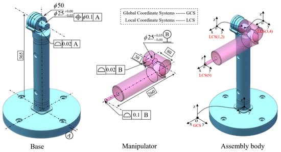
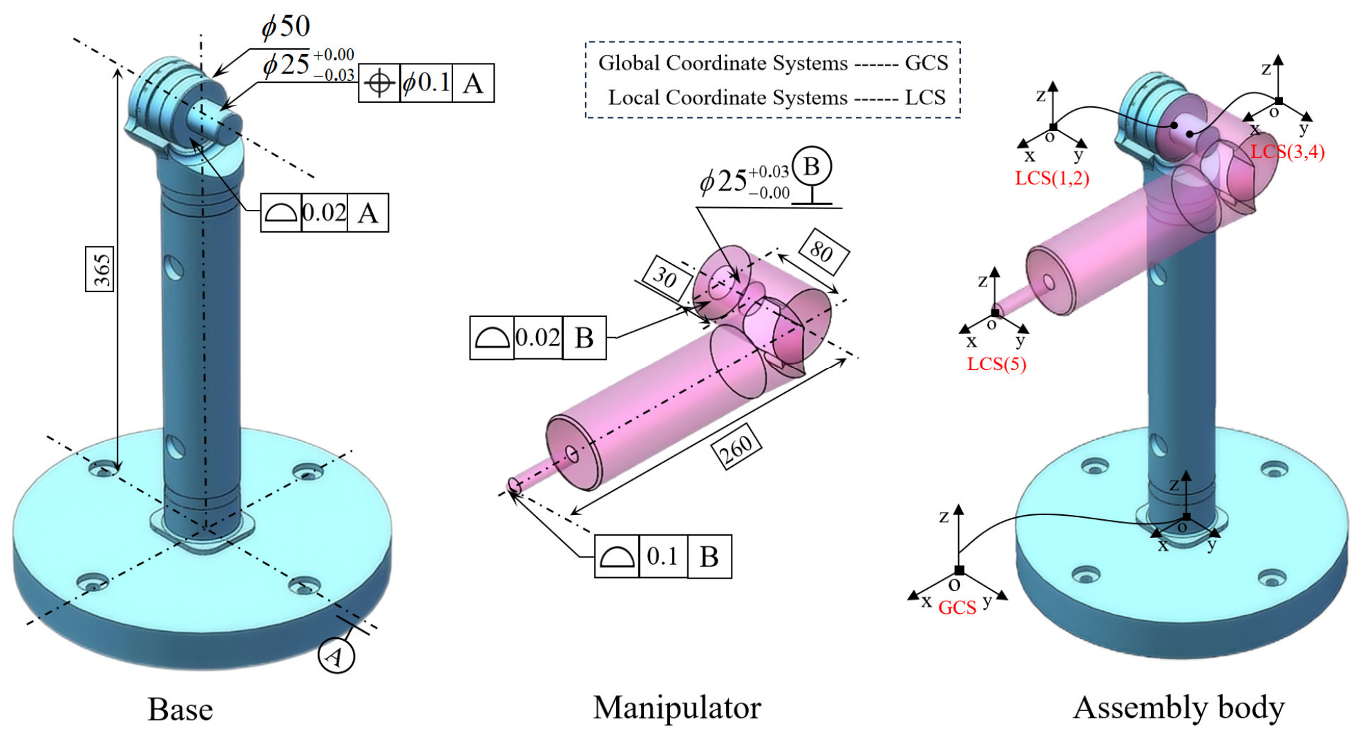
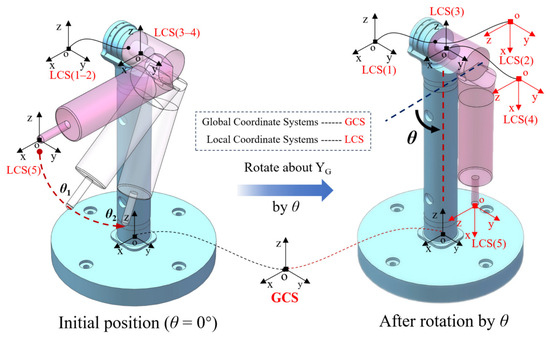
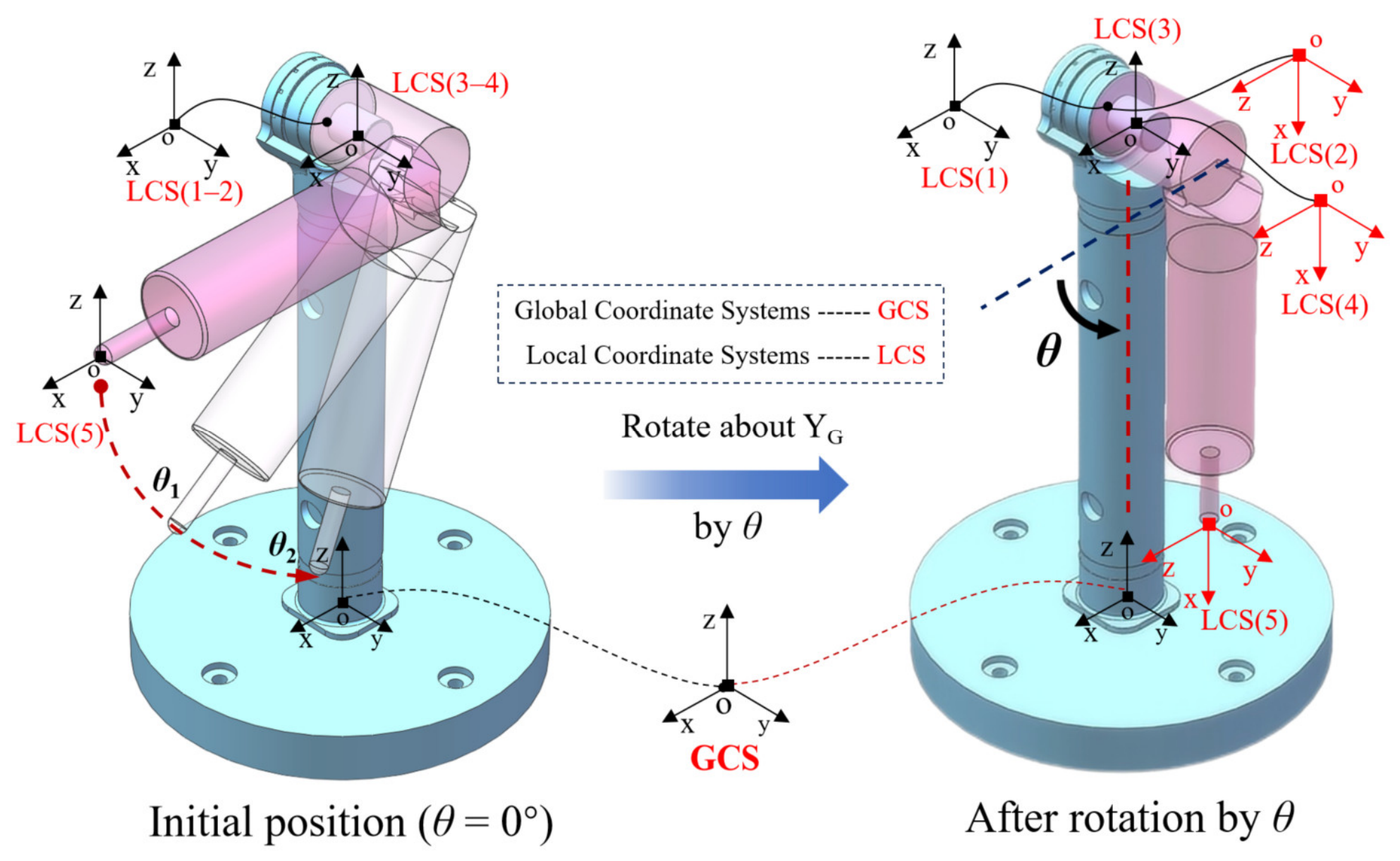
As shown in Figure 1 for a single-jointed robot, the whole system consists of two parts: the base and the manipulator arm. As shown in the assembly, a global coordinate system is established at the center of the base’s bottom surface. In addition, respective local coordinate systems are established at the center of each fit feature. Therefore, one global coordinate system and five local coordinate systems are defined. Combined with the relationship between the mating features, the mating situation between the arm and the base is analyzed. In the whole assembly, the base and the arm are firstly positioned by “face-to-face mating”, which restricts the three degrees of freedom of , , and , and constrains the and by the clearance fit of the axial holes, and lastly, the degree of freedom is retained. The single-jointed robot can only rotate around the y-axis, and the position deviation of its end in the global coordinate system is related to the rotation angle. As shown in the figure, the manipulator arm is parallel to the direction of the x-axis and perpendicular to the vertical bar of the base.
Figure 1.
A one-joint manipulator at initial position.
The matching characteristics between the base and the manipulator arm include shaft-hole clearance matching and end-face matching. When the two parts are matched, the base end has face and shaft features with contour, position and dimensional tolerances. The manipulator arm end has face and hole features with contour and dimensional tolerances. The two fit together so that the dimensional deviation is eventually transferred and accumulated at the end of the robot arm, which together affects the positioning accuracy of the end of the mechanism. At the same time, the uncertainty of the manufacturing tolerances should be considered, which can be expressed by a Torsor model.
In this paper, the Torsor model is used to describe the tolerances of the features involved in the fit in the geometric error transfer modeling of multi-axis robots. The specific expression of the Torsor model is: the variation in the features involved in the fit in their tolerance domain is expressed as six vectors in three-dimensional space. Specifically, vector is used to represent the amount of movement along the coordinate axis, and vector is used to represent the amount of rotation along the coordinate axis [33]. For tolerance uncertainty, all six vectors express the range of variation in the feature in the form of upper and lower limits in a uniform and simple form. Further, the upper and lower limits of the vectors are determined according to the actual feature type and tolerance range [34]. The mathematical expression of the rotation is written as
where the upper and lower labels indicate the upper and lower limits of the vector, respectively.
The Torsor model describes planar, cylindrical, and spherical features that can be applied to express geometric error transfer in a multi-axis robot. In addition, the Jacobian matrix is defined to describe tolerance transfer. The Torsor model can represent the variation in features in the tolerance domain by three movement vectors and three rotation vectors, which are similar to the joint degrees of freedom, and can be regarded as a “virtual joint” in this case. Each joint can be represented by a Jacobian matrix, which is passed down in the form of “three movements and three rotations” to the end of the whole system, realizing the accumulation and transmission of tolerances. The Jacobian matrix expresses the spatial geometric relationship between the joints, and the mathematical expression of the Jacobian matrix for each joint is shown in (2). Combining the Jacobian matrices of each joint gives the total Jacobian matrix, which expresses the spatial relationship of all tolerances, as shown in Equation (3).
In Equation (2), represents the transformation matrix of the local coordinate system of feature i with respect to the global coordinate system; is the position matrix of feature i to the target point. In order to meet the requirements of transfer and accumulation, also needs to be converted to the global coordinate system; the matrix expression is shown in (4), where n represents the final measurement point.
In Equation (4), , , , denote the distance from feature i to the final measurement point in the global coordinate system. And, the combination of the Torsor model, which is applicable to the expression of characteristic tolerance ranges, and the Jacobian model, which is applicable to the transmission and accumulation of tolerance ranges, is the Jacobian–Torsor model, with the mathematical expression shown in (5).
In Equation (5), FR (Functional requirement) is the target feature of tolerance analysis; FE (Functional element) is the functional feature involved in transfer and accumulation. The modeling of geometric error transfer in the multi-axis robot-assisted milling system involves the fit and rotation between the robotic arms and the tool, and contains a large number of planar and cylindrical features, as well as shaft and hole clearance fits. The Jacobian–Torsor model is suitable for 3D tolerance analysis.
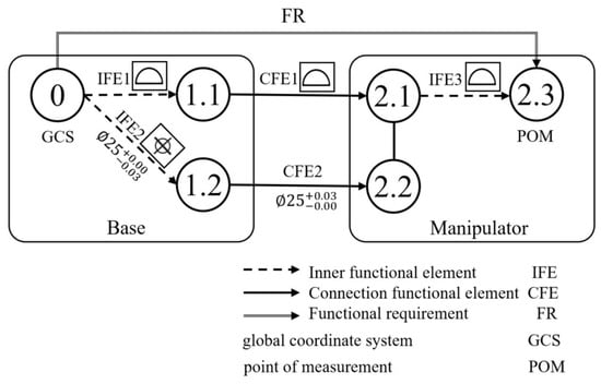
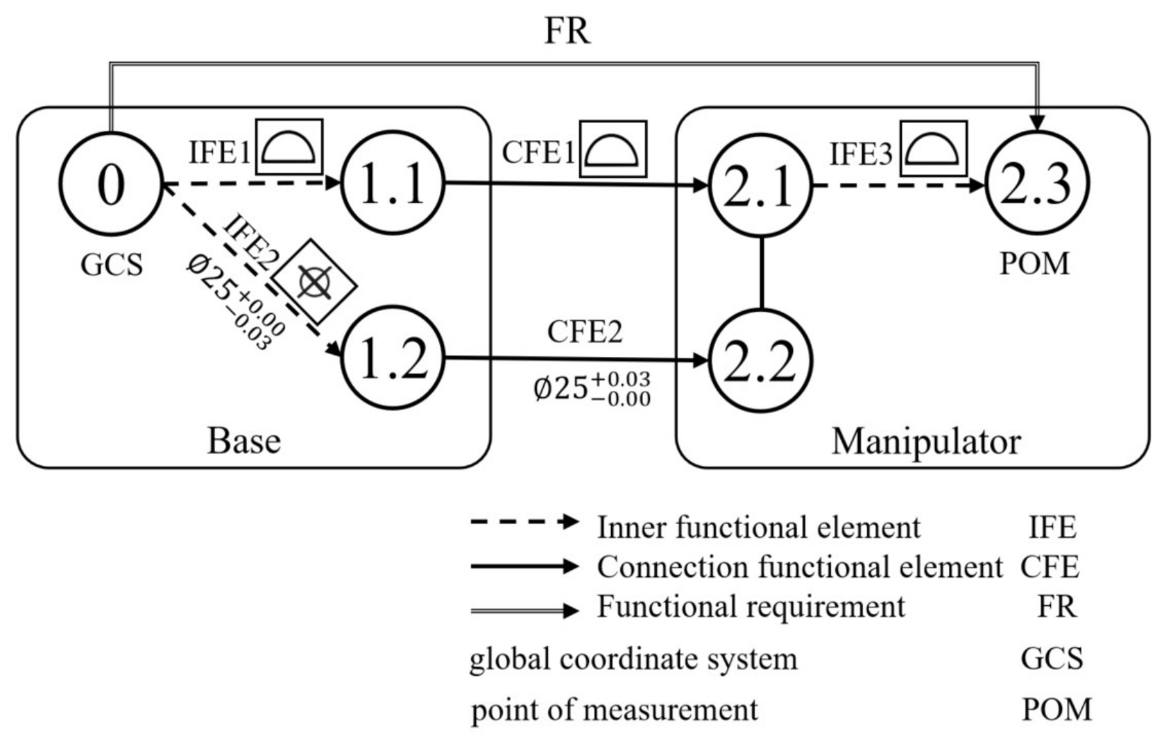
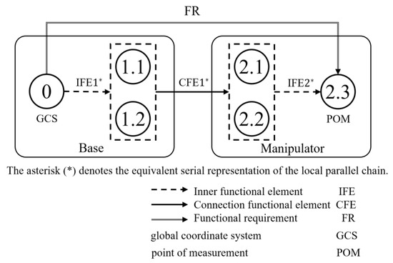
A connection diagram for geometric error transfer is determined from the assembly features, assembly hierarchy, and FR, as shown in Figure 2.
Figure 2.
Connection graph of the one-joint manipulator.
In Figure 2, the identifiers denote the geometric features involved in the assembly and geometric variation propagation chain. A hierarchical notation is adopted, where the integer part represents the assembly component and the decimal part represents the specific FE belonging to that component. Identifier 0 represents the bottom datum plane of the base, at which the global coordinate system is established. Identifiers 1.1 and 1.2 denote the two FEs on the base involved in the connection with the manipulator. Specifically, 1.1 corresponds to the circular end-face mating feature, whereas 1.2 corresponds to the shaft feature involved in the shaft-hole clearance fit. Similarly, identifiers 2.1 and 2.2 represent the corresponding mating FEs on the manipulator, where 2.1 is the circular end-face feature, and 2.2 is the hole feature involved in the shaft-hole clearance fit. Identifier 2.3 denotes the small end-face feature at the distal end of the manipulator, which is defined as both the measurement point and the FR in this case.
As shown in Figure 2, the geometric variation propagation chain of the single-joint manipulator contains a local parallel structure because the end-face mating path and the shaft-hole clearance-fit path coexist at the same joint. Each tolerance assigned to an FE defines an admissible geometric variation domain rather than a single deterministic deviation. Within this domain, the allowable variation in the FE is represented by a small displacement Torsor consisting of three translational components and three rotational components, which describe the possible small rigid-body motions of the feature under the prescribed dimensional and geometric tolerance constraints. Since the end-face mating and the shaft-hole clearance fit act simultaneously, they jointly constrain the relative pose between the base and the manipulator, and the corresponding Torsor components are therefore not always independent. However, the conventional Jacobian–Torsor model is primarily formulated for fully serial variation propagation chains. If one of the two mating paths is neglected to simplify the local parallel structure into a serial chain, the tolerance information associated with the omitted path is lost, which may reduce the accuracy of the predicted variation range. Therefore, the Torsor models associated with the two mating paths are merged to construct an equivalent serial representation. For this local parallel chain, independent variation components are combined through a union operation, whereas overlapping or mutually constrained components are determined through an intersection operation. The resulting equivalent Torsor preserves the combined tolerance effects of both mating paths and can subsequently be propagated to the FR through the Jacobian–Torsor model. The specific operation is to modify and integrate the Torsor model that forms the parallel structure, so that the new Torsor model can express the feature and tolerance information of the original locally parallel dimensional chain. Firstly, it is necessary to write the Torsor model of each FE in the original locally parallel relational chain, as the transformation rules of parallelism are discussed in detail later. The Torsor model formulas for planar features are shown in (6), and the Torsor model formulas for cylindrical features are shown in (7).
In Equation (6), and represent the lower and upper limits of the plane features, and represent the lengths of the two sides of the plane, respectively; in Equation (7), represents the tolerance range of the hole or the shaft, and in the case of clearance fits, the amount of clearance between the hole and the shaft, and represents the depth of the hole or the axial length of the shaft.
2.2. Analysis Method for Local Parallel Chain
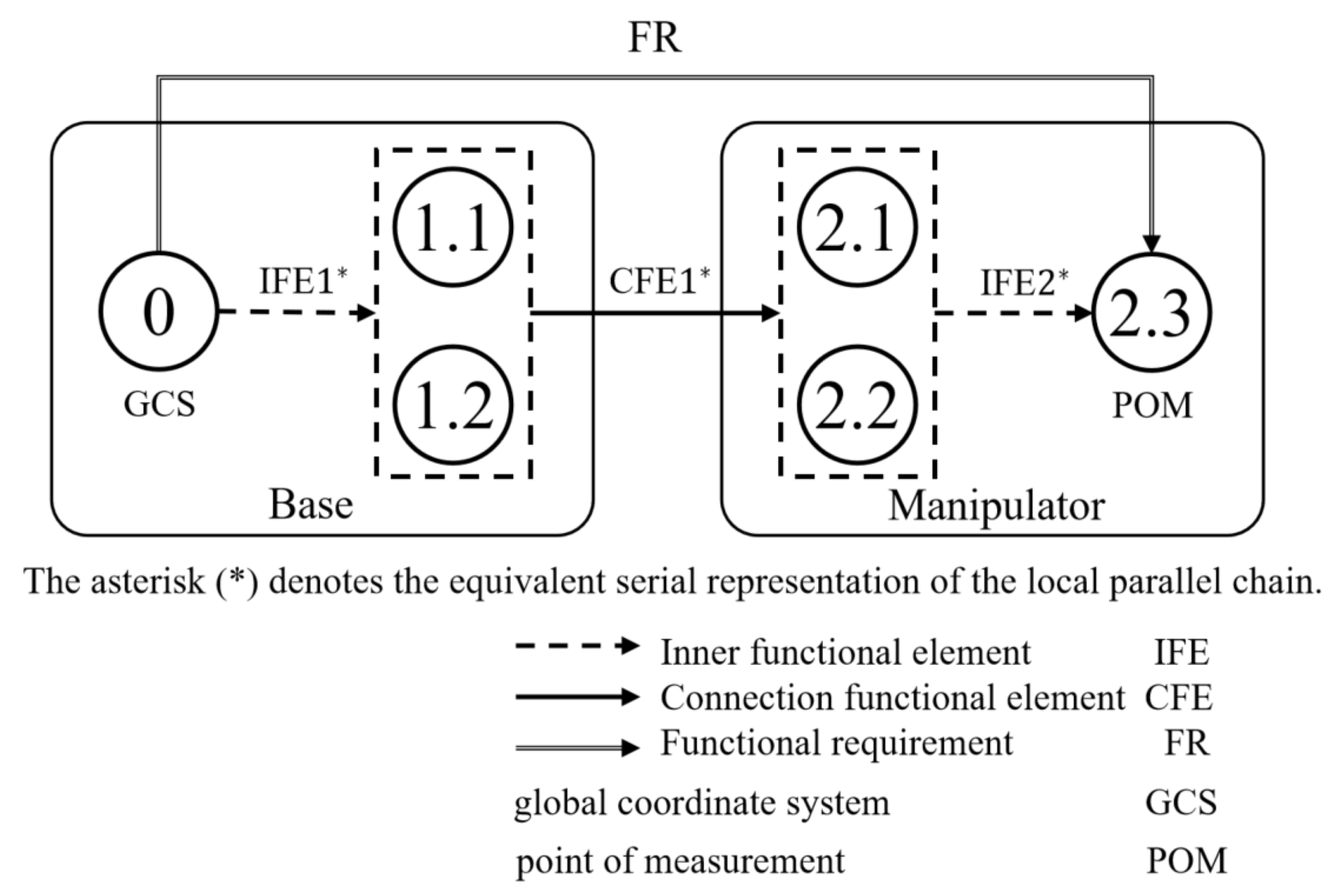
Taking this case as an example, if only the face features are considered, the positional degree tolerance as well as the dimensional tolerance of the hole axis will be completely ignored; on the contrary, if only the hole axis features are considered, the contour tolerance of the face contact will be ignored, which will cause inaccuracy of the results. Therefore, we convert the parallel relationship of the two groups of features into a series relationship here, and the converted link diagram is shown in Figure 3.
Figure 3.
Connection diagram of series chain.
In Figure 3, the identifiers follow the same component–FE hierarchical notation as defined in Figure 2. Therefore, the identifiers in Figure 3 correspond to the same physical features as those in Figure 2, including the base features (1.1 and 1.2), the manipulator mating features (2.1 and 2.2), and the measurement feature (2.3). Figure 3 presents the equivalent serial topology obtained by transforming the original local parallel connection. The dotted boxes indicate the FE groups whose Torsor models are merged to obtain equivalent FE representations for the serial topology.
After obtaining the Torsor model for each FE, the local parallel connection is transformed into an equivalent serial representation. From the fit relationship, it can be seen that the parallel dimensional chain consists of a shaft-hole clearance fit and two end-face fits. As indicated by the dotted boxes in Figure 3, the Torsor models of the planar and cylindrical FEs belonging to the same component are merged to construct an equivalent FE. The component-wise merging rule proposed in this study is based on the admissible variation domains and kinematic compatibility conditions of the mating FEs. Each Torsor defines a six-dimensional admissible variation domain consisting of three translational components and three rotational components. Since the end-face mating path and the shaft-hole mating path act simultaneously on the same relative pose, the equivalent Torsor must retain the independent variation components while satisfying the common constraints imposed by both mating paths.
Specifically, when the corresponding Torsor components describe independent admissible variations and do not impose overlapping constraints on the same generalized displacement, their contributions are retained through a “union” operation. When the same Torsor component is simultaneously constrained by both mating paths, its equivalent admissible range must satisfy both constraint domains and is therefore determined through an “intersection” operation. Here, the “union” operation denotes the retention of independent variation components rather than the direct numerical union of two conflicting tolerance intervals. Take the merging operation of IFE1 and IFE2 of the base as an example, since the corresponding vectors of the two Torsor models are completely independent of each other without overlapping, they are taken as the union; while the corresponding vectors have overlapping ranges and are not independent of each other, the new vector is taken as the intersection of the two. In summary, for the locally parallel dimensional chain structures of IFE1 and IFE2, the variation equations of the vectors in the Torsor model are shown in (8).
In Equation (8), the operator “П” denotes either a “union” or an “intersection” operation. The union operation is used to retain independent variation components, whereas the intersection operation is applied when the same generalized displacement component is simultaneously constrained by both mating paths. The distinction from previous parallel-chain treatments is that the present equivalent transformation is subsequently embedded in a pose-dependent Jacobian–Torsor model, rather than being used only for tolerance accumulation in a static assembly.
2.3. Modified Jacobian Torsor Model for Geometric Variation in Multi-Axis System
The proposed formulation is established under quasi-static, rigid-body, and small-displacement assumptions. The base, links, spindle, and tool are assumed to remain rigid, whereas manufacturing and assembly deviations are represented as infinitesimal rigid-body displacements of the associated ideal FEs using small displacement Torsors. The present model does not include cutting-force-induced elastic deformation, gravity-induced deflection, joint and link compliance or workpiece deformation. Therefore, the resulting tool tip deviations represent the tolerance-induced geometric-error component rather than the total machining error under actual cutting conditions.
In the unified Jacobian–Torsor model, the Jacobian matrix of feature to feature is written to represent the propagation in multi-axis assembly for a certain configuration in quasi-static state. Whereas, for a milling system, the geometric variations are different with the motion locations and poses during the milling motion process.
The motion of this single-jointed robotic system is rotation around the Y-axis, and the rotation angle can be used to inscribe the current new bit position. As shown in Figure 4, the angle is rotated clockwise around the Y-axis from the default bit pose to explore the relationship between the geometric deviation of its target point in the global coordinate system and the rotation angle.
Figure 4.
Position change in the manipulator.
As shown in Figure 3, there are three FEs [IFE1*,CFE1*,IFE2*] in the link after transforming into a full series connection, and the subscripts are set to be 1,2,3, respectively, for the convenience of describing their Jacobian matrices updated with angle. As shown in Figure 4, when the operator arm rotates by an angle , the local coordinate system defined on the manipulator rotates and is no longer consistent with the global coordinate system, so the transformation matrix in the Jacobian matrix corresponding to the local coordinate system will also change. In addition, since the rotation drives the spatial position of the target point FR to change, if the distance from each feature to the target point in the global coordinate system changes, the position matrix in the corresponding Jacobian matrix of that feature will also change. For the Torsor model of each feature, the expression of the Torsor model does not need to be updated because the expression of the Torsor is only related to the fit relationship, the feature type and the tolerance range, and has nothing to do with the spatial position of the feature. Therefore, the formula for the modified Jacobian–Torsor model is shown in (9), which contains the angle variable.
In Equation (9), the upper-left block transforms the local translational variation in FEi into the global coordinate system. The upper-right block represents the lever-arm effect through which an angular variation in FEi produces an additional translational deviation at the FR. The lower-right block transforms the local angular variation into the global coordinate system, whereas the lower-left zero block indicates that an infinitesimal translational variation does not directly generate an orientation variation. Therefore, the pose dependence of the modified Jacobian arises from both the FE orientation and the FE-to-FR spatial lever arm.
In the single-axis kinematic model, it is assumed that the system undergoes a rotation about an arbitrary unit vector in the global coordinate system, denoted as with a rotation angle . The generalized rotation matrix is constructed using Rodrigues’ rotation formula:
where is the identity matrix and is the skew-symmetric matrix associated with the unit rotation axis . It should be emphasized that in Equation (10) represents the finite nominal rotation of the robotic system between two configurations, rather than a small geometric deviation. Thus, the finite nominal motion is described by an exact rigid-body rotation, while the tolerance-induced deviations are propagated through the first-order Jacobian relationship.
Assume that the kinematic chain consists of FEs. Let node correspond to the FE at which the rotation occurs (e.g., a revolute joint). Based on the system transmission topology, all nodes can be partitioned into two mutually exclusive subsets:
(1) Preceding static FE set : FE nodes located before the rotation node , whose global poses remain unchanged during the rotation (i.e., );
(2) Subsequent co-rotating FE set : FE nodes including and following node , whose global poses rotate rigidly with the motion of node (i.e., ).
For any functional FE, the updated orientation matrix with respect to the global coordinate system, denoted as , is given by:
The construction of the Jacobian matrix depends on the relative position vectors between each FE and the FR at the end-effector. Let denote the initial relative position vector from FE to the FR in the nominal configuration. When a rotation of angle is applied at node , for the co-rotating FE set , the FE and the FR belong to the same rigid rotational subsystem, and their relative position vectors undergo a pure rigid-body transformation:
For the preceding static FE set , although the absolute positions of the FEs in the global reference frame remain unchanged, the relative vectors to the end-effector change due to the motion of the FR. According to the kinematic vector-chain relationship, the updated relative position can be decomposed into two components: (1) the constant vector from FE to the rotation node , i.e., ; and (2) the rotated vector from node to the FR, expressed as . Therefore, the mapping relationship is given by
Finally, the updated relative position vector is mapped into the corresponding updated transformation matrix :
Equation (14) converts the updated FE-to-FR relative-position vector into the corresponding cross-product matrix. When this matrix is multiplied by the global angular variation in the FE, it yields the additional linear deviation generated at the FR through the lever-arm effect. Substituting the updated orientation matrix from Equation (11) and the updated lever-arm matrix from Equation (14) into Equation (9) yields the pose-dependent Jacobian matrix. It should be noted that only these two geometric terms are updated with the nominal system pose; the FE Torsor definitions and their tolerance bounds remain unchanged because they depend on the feature type, mating relation, and prescribed tolerance rather than on the spatial configuration. In this manner, the same Jacobian–Torsor topology can be repeatedly evaluated throughout the motion space, thereby extending the formulation from fixed-configuration tolerance analysis to full-space geometric variation propagation while preserving the tolerance constraints introduced by local parallel mating chains.
3. Simulation Methodology
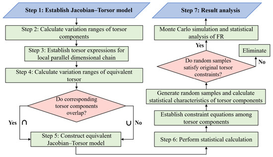
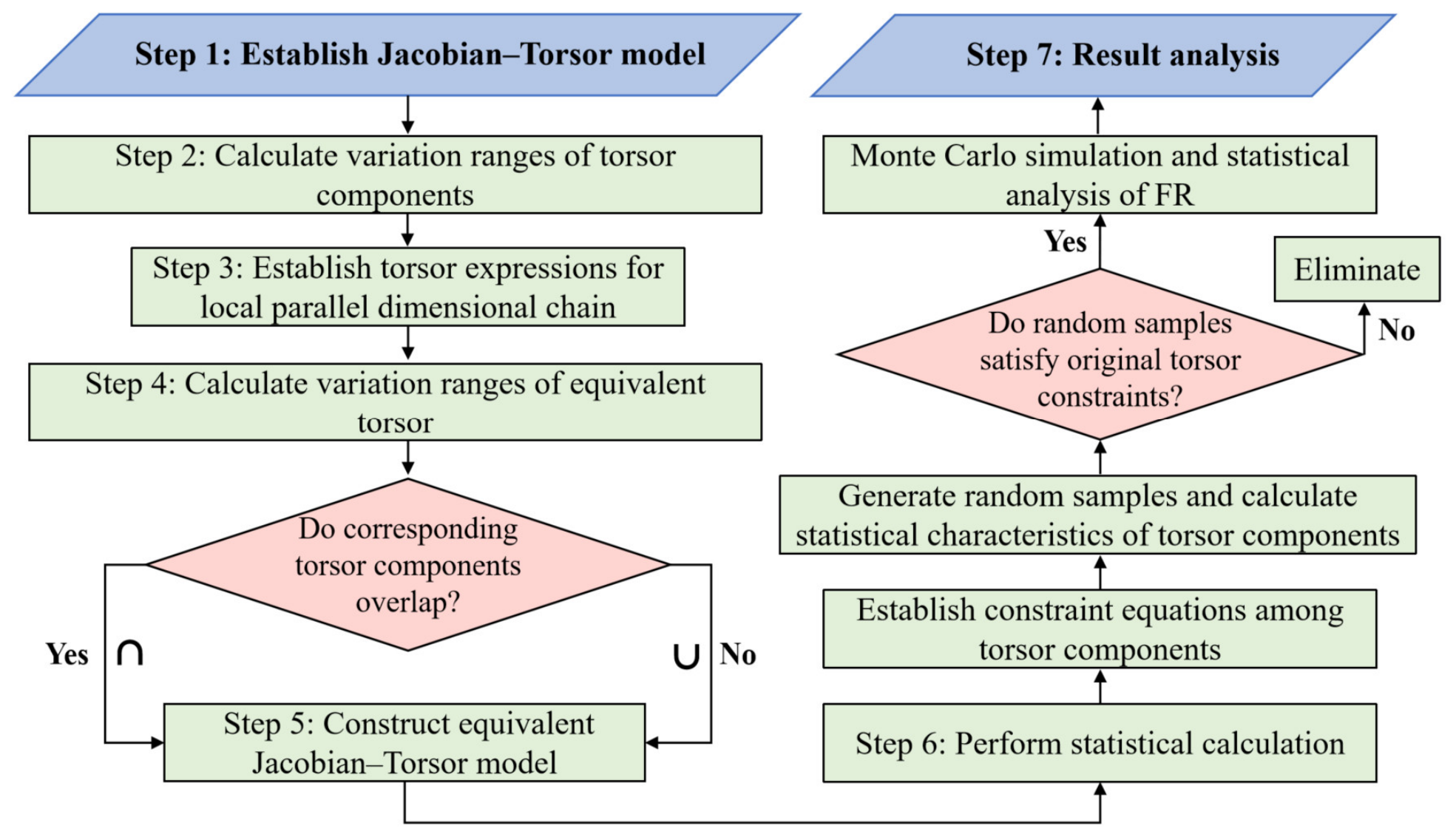
After obtaining the Jacobian–Torsor model for describing the geometric error transfer, the model can be solved for both extreme value and statistical solutions. From the engineering and applicability point of view, the statistical solution has more practical engineering significance. In order to find the statistical solution of the model, this paper proposes a simulation algorithm to study the tolerance uncertainty through Monte Carlo simulation, which introduces the random variation in the vectors and the constraint equations in the Torsor model into the Jacobian–Torsor model to achieve an accurate and reliable tolerance analysis and to find the statistical solution of the model. The specific constraints for planar and cylindrical features are shown in Equations (15) and (16), which represent further range constraints on a Torsor model. The feature is guaranteed to be within the tolerance variation range without overshooting after small displacements (three movement vectors plus three rotation vectors).
In Equation (15), ; and in Equation (16), , i.e., the axial length of the cylindrical feature.
During the Monte Carlo simulation, the Torsor components are modeled using normal distributions as a representative baseline assumption for stable manufacturing processes, with the prescribed tolerance limits corresponding to the selected ±3σ ranges [35]. Candidate samples that exceed these limits or violate the coupled constraints of the planar and cylindrical Torsors are rejected, ensuring that all inputs propagated through the Jacobian–Torsor model remain within the original tolerance domains. The resulting statistical predictions are conditional on the assumed input distributions; however, the proposed propagation framework is not distribution-specific and can directly incorporate empirical or fitted non-normal distributions when process measurement data are available. The Monte Carlo sample size was selected by balancing statistical stability and computational cost. Although a smaller sample set can provide estimates of the main statistical quantities, 40,000 admissible samples were conservatively adopted to further reduce random sampling fluctuations and improve the stability of the estimated output dispersion. This sample size enables more robust estimation of the mean, standard deviation, histograms, and distribution tails, while remaining computationally affordable for the present Jacobian–Torsor model. According to the statistical theory, the effect of each tolerance feature on the positional degree of the end measurement point can be obtained. The flow chart of the simulation algorithm for the specific Monte Carlo simulation is shown in Figure 5.
Figure 5.
Flow chart of geometric variation based on MC simulation.
4. Case Study
4.1. Case 1: One-Joint Manipulator
Based on the Torsor formula and the labeled tolerances in Figure 1, all the feature Torsor s are obtained as shown in Table 1.
Table 1.
Torsor model of each feature.
After obtaining the Torsor model for each feature, the local parallel Torsor model is considered to be transformed into a series model. The transformed Torsor model is shown in Table 2.
Table 2.
Torsor model of series dimension chain.
Subsequently, the total Jacobian matrix can be obtained according to Equations (2)–(4), and the final Jacobian–Torsor model for this system can be obtained by bringing the total Jacobian matrix and the Torsor model into Equation (5), as shown in Equation (17):
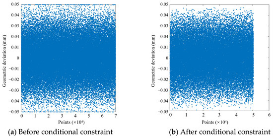
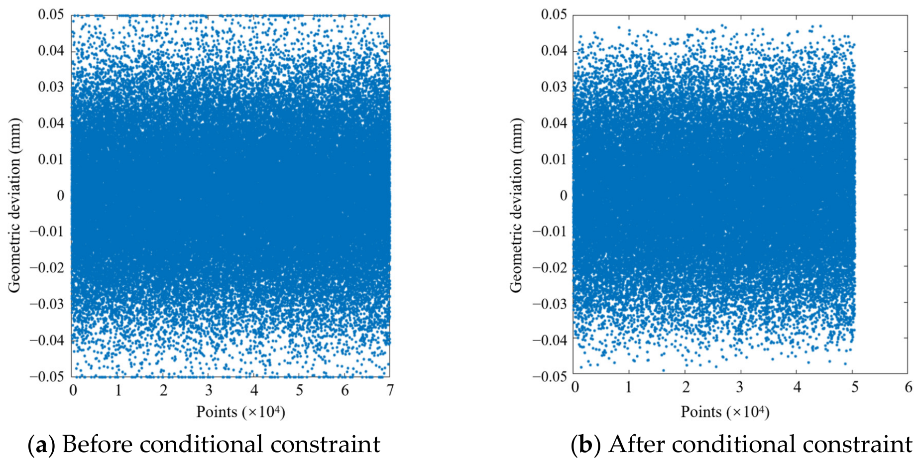
As shown in Figure 5, before performing 40,000 Monte Carlo simulations, the randomly generated point sets of each vector in the Torsor model need to be coupled and constrained, and the points that do not meet the constraints need to be culled out. Taking the u-vector culling in the Torsor model of IFE1* as an example, during the implementation of the algorithm, an excess of 40,000 randomly distributed point sets need to be generated for screening. Taking the number of points in the point set as the horizontal coordinate and the specific deviation value of each random point as the vertical coordinate, the scatter distribution of the u-vector in the Torsor model before and after the conditional constraint is plotted, as shown in Figure 6. It can be intuitively seen that the point sets of the vectors are filtered significantly at the boundary, which is also consistent with the actual situation, because when the movement vector is large, the rotation vector can only take a small value, and vice versa. In terms of the total number of scattered points, the point set of the vector is reduced from 70,000 to 50,418 discrete points after the condition constraints, which makes the simulation results more accurate.
Figure 6.
Scatter distribution of u-vector before and after conditional constraints.
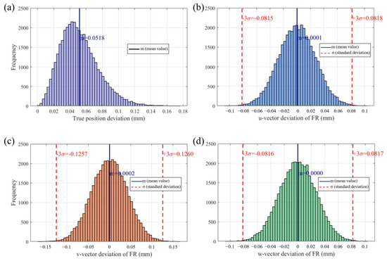
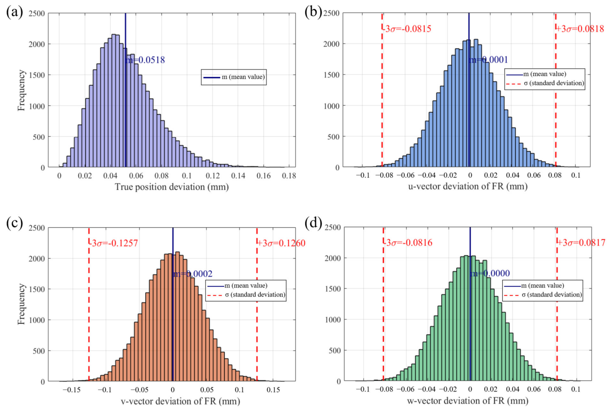
The standard deviation and mean value of FR are calculated by Monte Carlo simulation. A total of four outputs are set up, namely the following: 1. the absolute position degree of FR and its mean value; 2. the distribution of u-direction vector deviation of FR as well as its standard deviation and mean value; 3. the distribution of v-direction vector deviation of FR as well as its standard deviation and mean value; and 4. the distribution of w-direction vector deviation of FR as well as its standard deviation and mean value; all of the above outputs are presented in the form of a frequency histogram as shown in Figure 7.
Figure 7.
Monte Carlo simulation output results for the single-joint manipulator: (a) true position deviation; (b) u-deviation; (c) v-deviation; (d) w-deviation.
As shown in Figure 7, the solution of the geometric deviation distribution of the end target feature of a single-jointed robot is achieved by the Jacobian–Torsor model. It can be seen that the mean value of the absolute positional distribution of the tool tip point is about 0.0518 mm. Additionally, the deviation vectors along the axes of the coordinate system and their respective deviation ranges can be precisely determined.
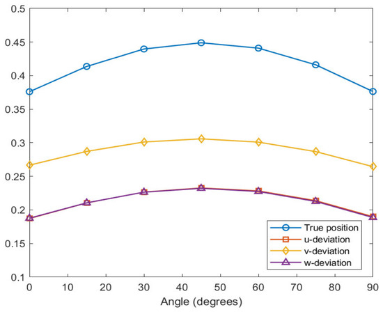
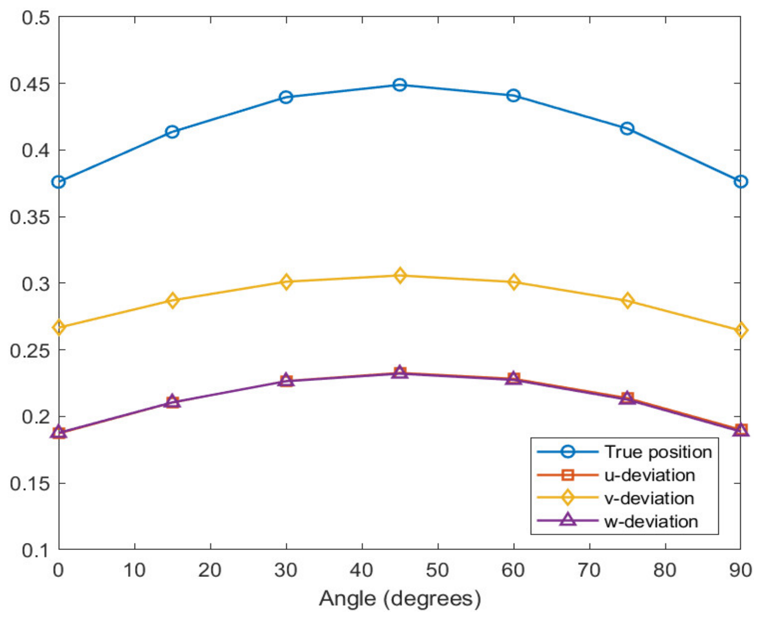
Modified Jacobian–Torsor modeling with angular variables is used to investigate the relationship between the rotation angle and the degree of geometric deviation. It can be seen that, for seven angles [0, 15, 30, 45, 60, 75, 90], the upper boundary values obtained under 7 angles are shown in Table 3, and the trend graph of the deviation is shown in Figure 8.
Table 3.
Output results at different angles.
Figure 8.
Pose-dependent geometric deviation trends of the single-joint manipulator.
As shown in Figure 8, the true-position and directional deviations first increase and then decrease as the manipulator rotates about the fixed -axis, with their maximum values occurring near . This trend results from the pose-dependent projection and lever-arm terms in the Jacobian matrices. Between and , the sine- and cosine-related sensitivity terms become simultaneously significant, increasing the coupling and amplification of the tolerance-induced deviations; beyond , the corresponding sensitivities decrease in the complementary direction. The similar magnitudes of the - and -direction deviations are attributable to the approximate geometric symmetry of the single-joint mechanism and the comparable lever-arm amplification in these two directions. Nevertheless, the two components are calculated independently, and their small differences arise from the distinct contributions of individual tolerance sources and Monte Carlo sampling variability.
4.2. Case 2: Seven-Axis Robot-Assisted Milling System
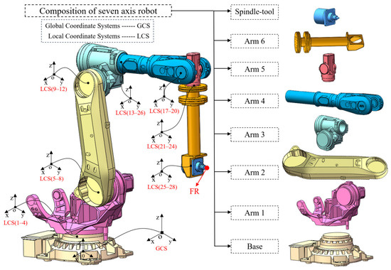
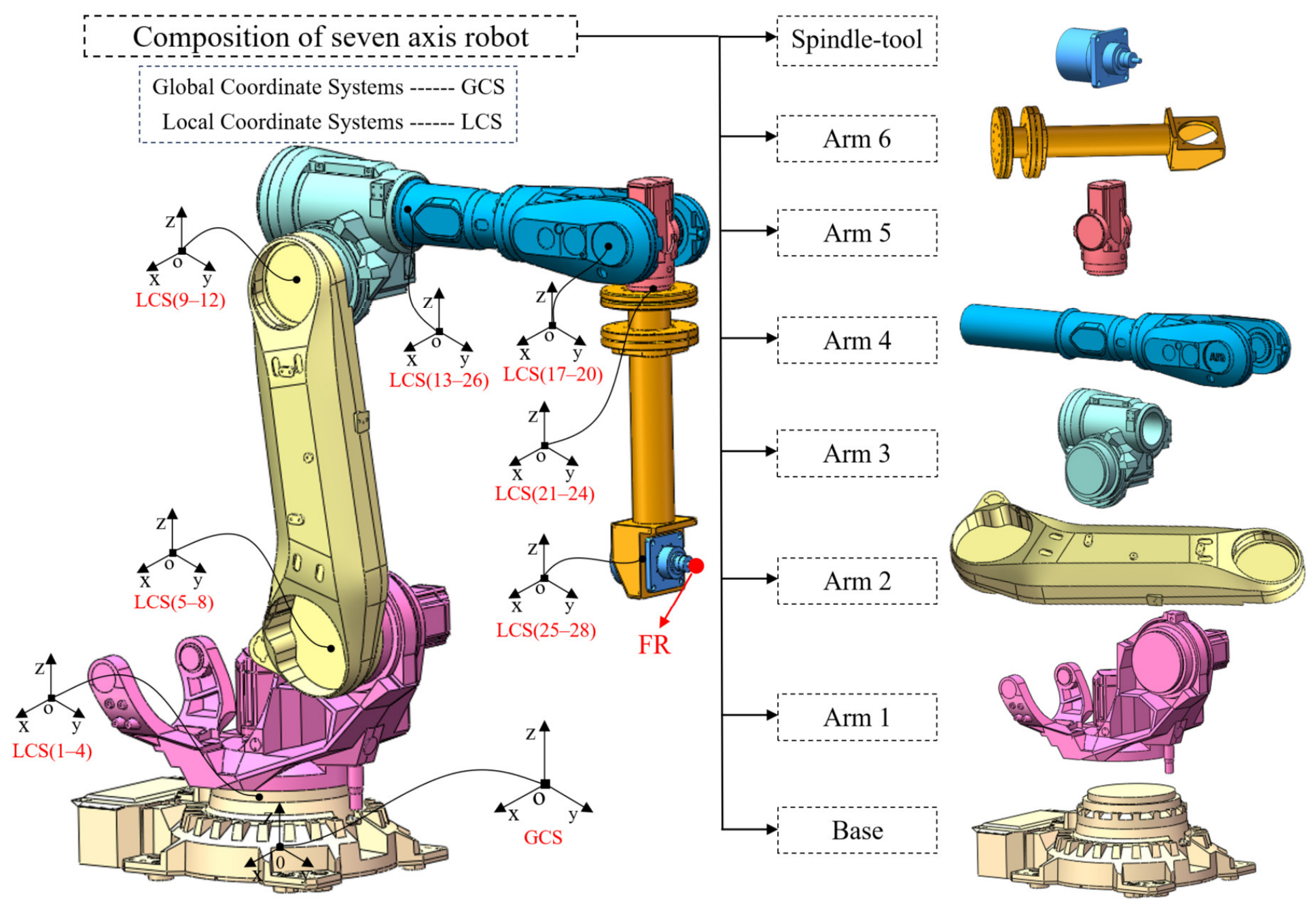
As shown in Figure 9, the robotic milling system consists of a fixed base, six serial links, and a terminal spindle–tool assembly connected through seven revolute joints. The configuration shown in Figure 9 is defined as the nominal reference configuration, with a global coordinate system established at the center of the base bottom surface and the tool tip defined as the output FR. Each joint contains two end-face FEs and one shaft–hole mating pair, resulting in 28 local FE coordinate systems. The terminal machining unit comprises a high-speed electric spindle with an HSK-A63 tool interface. An ER32 collet chuck with a nominal 8 mm collet is used to clamp cylindrical-shank tools, such as end mills and drills. The extension structure is connected to the distal flange of the sixth link through a bolted flange joint, while the spindle is rigidly mounted to the extension structure through predesigned mounting holes and bolted connections.
Figure 9.
System composition and modeling of 7-axis robot.
For each joint, the assembly consists of two types of mating features, including face-to-face contacts and hole-shaft fits. The geometric deviations of these features are characterized by profile tolerances, circular runout, and dimensional tolerances, which are assigned according to the corresponding functional requirements of each joint. The corresponding planar and cylindrical FEs are assigned profile, circular-runout, and dimensional tolerances, as summarized in Table 4. In particular, the tolerance magnitudes vary across different components, with profile tolerance values ranging from 0.02 mm to 0.03 mm, circular runout fixed at 0.01 mm, and dimensional tolerance intervals defined based on the allowable clearance or interference of each hole-shaft pair. These tolerance values are selected as representative engineering inputs for model validation and statistical analysis, rather than representing the exact manufacturing tolerances of a specific robotic system. In the proposed Jacobian–Torsor model, each tolerance defines an admissible geometric variation domain, from which random deviations are sampled in the Monte Carlo simulation process. These tolerance specifications are used as the input parameters of the geometric variation propagation model.
Table 4.
Geometric and dimensional tolerance inputs for the seven-axis robot.
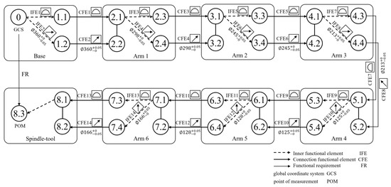
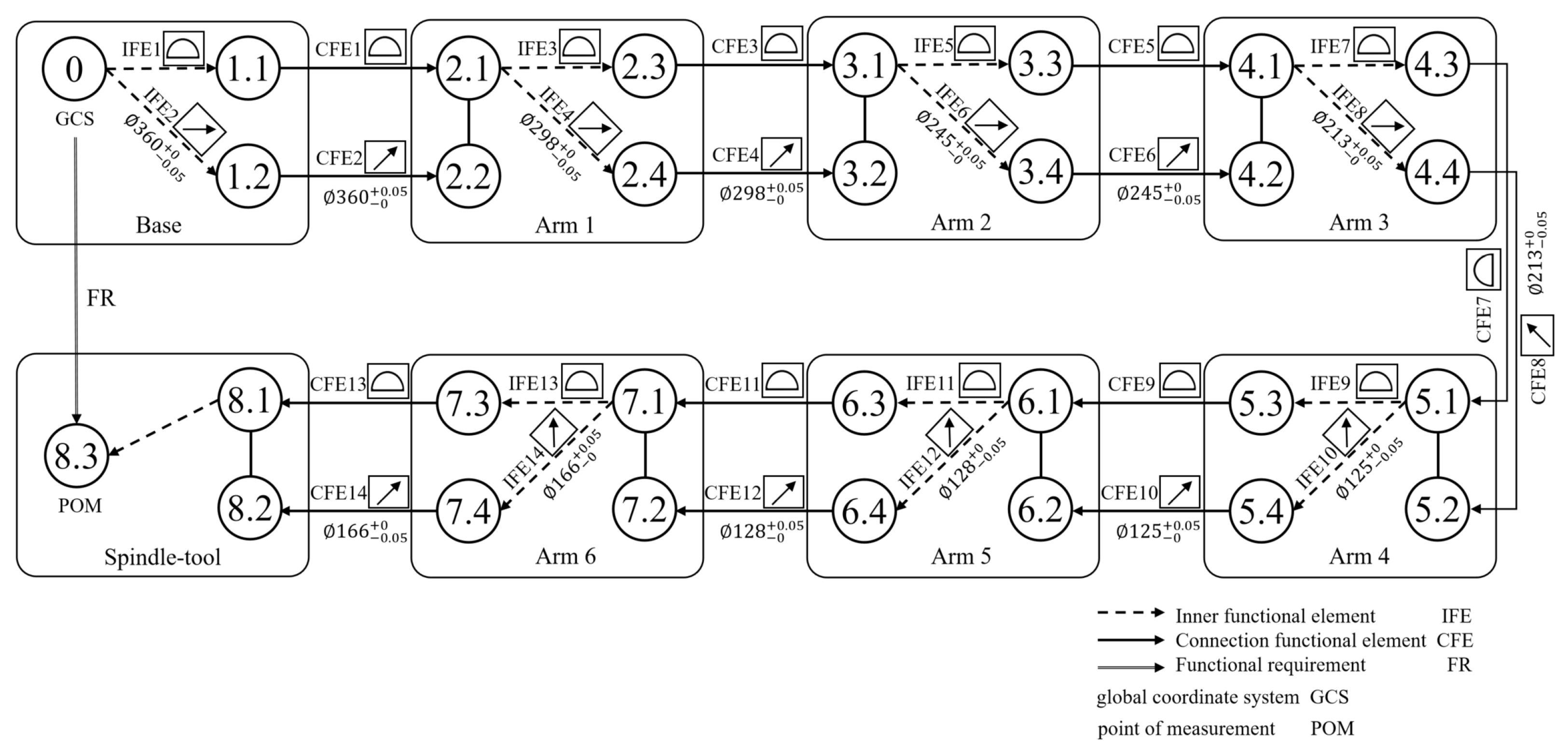
Based on the assembly characteristics of the seven-axis robotic system, the assembly hierarchy between components, and the FR, a connectivity diagram for geometric error transfer is determined, as shown in Figure 10; it is handled in the same way as that of a single-jointed robot.
Figure 10.
Connection diagram of 7-axis robot system.
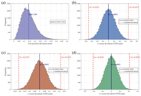
The case study is evaluated under quasi-static and rigid-body assumptions. The base is fully fixed, and no external cutting loads, gravity-induced deformation, thermal deformation, vibration, or servo errors are introduced. For the initial statistical analysis, all joint variables are maintained at the nominal reference configuration shown in Figure 9. After establishing the Jacobian–Torsor model, the statistical solution was solved by 40,000 Monte Carlo simulations to calculate the standard deviation and mean of FR. In the result output, the same four outputs are set, which are the same as those of the single-joint robot case, and all the above four outputs are presented in the form of frequency histograms, as shown in Figure 11.
Figure 11.
Monte Carlo simulation output results for the 7-axis robot system: (a) true position deviation; (b) u-deviation; (c) v-deviation; (d) w-deviation.
As the results shown in Figure 11, the influence of the tolerance characteristics on the accuracy of the end tool tip can be visualized, and the mean value as well as the standard deviation of the output term can be assessed to determine the positioning accuracy of the tool tip point as well as the distribution of the geometrical deviation. It can be seen that the mean value of the absolute positional distribution of the tool tip point is about 0.139 mm, and in addition, the distribution of the deviation vectors along the axes of the coordinate system and the range of deviation can be accurately settled.
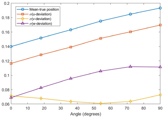
In the single-joint manipulator case, the geometric deviation of the target feature varies with the rotation angle, but its variation trend is relatively regular because of the simple kinematic structure and limited coupling effects. For the seven-axis robot-assisted milling system, the relationship between the geometric deviation and the joint angle becomes more complex due to the coupled propagation of geometric variations through multiple joints. Therefore, the pose-dependent geometric deviation of the seven-axis system is further investigated in this case. Starting from the default position of 0°, arm 5 is rotated clockwise about the X-axis. The Jacobian–Torsor model is updated and solved by Monte Carlo simulation at every 18° interval until the rotation angle reaches 90°. In total, six groups of simulation results are obtained, as listed in Table 5. Taking the rotation angle as the horizontal axis and the mean value or standard deviation of the four output terms as the vertical axis, the corresponding deviation trends are plotted in Figure 12.
Table 5.
Monte Carlo output results at different angles.
Figure 12.
Pose-dependent geometric deviation trends of the 7-axis robot system.
As shown in Figure 12, the pose-dependent trends of the seven-axis system are more complex than those of the single-joint mechanism because the rotation associated with link 5 simultaneously changes the orientations of the downstream FEs and the spatial lever arms from multiple upstream error sources to the tool tip. Consequently, the tolerance contributions are redistributed among the global directions through the pose-dependent Jacobian matrices. The increasing -direction deviation indicates an increase in the corresponding error-projection sensitivity and effective angular-error lever arms. The -direction deviation initially decreases because some projected contributions become less sensitive or partially offset one another, and then increases as the downstream orientations change further and these contributions become reinforcing. The -direction deviation increases initially but approaches a nearly stable level at larger angles because the associated projection and lever-arm terms gradually approach their geometric limits. As a result, the growth of the - and -direction dispersions outweighs the intermediate decrease in the -direction deviation, leading to a continuous increase in the mean true-position deviation from 0.1399 mm at to 0.1934 mm at . These results demonstrate that the pose-dependent accuracy variation is governed by the redistribution and amplification of fixed tolerance inputs through the changing system geometry.
The predicted FR deviations should be interpreted as the tolerance-induced geometric component of the tool tip error under quasi-static and rigid-body conditions, rather than as the total machining error under actual cutting loads. For a prescribed tool pose, the component of the translational deviation normal to the nominal machined surface contributes directly to local dimensional and profile errors, whereas the tangential components mainly affect tool-path placement and contour tracking. For compensation, the systematic or mean directional deviation can be used as a feedforward path offset, whereas the statistical dispersion defines an uncertainty envelope that cannot be removed by a single deterministic correction. Therefore, the proposed model provides a geometric basis for accuracy assessment, posture selection, and subsequent tool-path compensation, while practical compensation under milling loads requires integration with process- and deformation-related error models.
5. Conclusions
This study proposed a full-space geometric variation propagation modeling method for multi-axis robotic milling systems by extending the Jacobian–Torsor framework to account for local parallel chains and pose-dependent kinematic transformations. The main conclusions are summarized as follows:
- A unified geometric variation propagation model was established for multi-axis robotic milling systems. Manufacturing and assembly variations in planar and cylindrical FEs were represented using small displacement Torsors, while feature-to-feature Jacobian matrices were used to propagate these variations to the tool tip FR. For joints containing simultaneous end-face contacts and shaft-hole fits, the local parallel chains were converted into equivalent serial representations through component-wise union and intersection operations, thereby retaining the tolerance information of both mating paths.
- The conventional fixed-configuration Jacobian–Torsor model was extended to full-space, pose-dependent analysis. The orientation matrices and relative position matrices in the Jacobian formulation were updated according to the system rotation. Therefore, the proposed model can describe how manufacturing and assembly deviations propagate under continuously varying system poses without reconstructing the complete model for each configuration.
- The constrained Monte Carlo procedure enabled statistical evaluation of the tool tip geometric variation. For the single-joint manipulator at the initial configuration, the mean true position deviation of the FR was approximately 0.0518 mm. As the rotation angle increased from 0° to 90°, the upper-bound true position deviation first increased from 0.3761 mm to a maximum of 0.4490 mm at 45°, and then decreased to 0.3764 mm at 90°, demonstrating a clear pose-dependent but relatively regular variation pattern.
- The seven-axis robotic milling case further demonstrated the effect of multi-joint coupling on spatial accuracy. At the initial configuration, the mean true position deviation of the tool tip was approximately 0.139 mm. When the fifth link was rotated from 0° to 90° at 18° intervals, the true position deviation generally increased with the rotation angle. The u-direction deviation increased, the v-direction deviation decreased initially and then increased, and the w-direction deviation increased with a gradually decreasing growth rate. Geometric variation propagation in a multi-joint system is strongly configuration-dependent and more complex than that of a single-joint mechanism.
Overall, the proposed method provides a systematic means of linking manufacturing and assembly tolerances to the statistical spatial accuracy of the tool tip. The proposed method provides a theoretical basis for analyzing tolerance-induced accuracy variations, evaluating pose-dependent tool tip accuracy, and supporting subsequent workspace and tolerance optimization. The current model is established under quasi-static, rigid-body, and small-displacement assumptions. Accordingly, the reported results represent tolerance-induced geometric variations rather than the total machining errors under cutting loads. Future work will incorporate load-induced structural deformation and experimental measurements to further evaluate the model under actual milling conditions.
Author Contributions
Conceptualization, S.L.; methodology and software, Y.X. and Q.G.; writing—original draft preparation, S.L. and Y.X.; writing—review and editing, S.L., Y.X., Y.J. and Q.G.; supervision, S.L. and S.J.; funding acquisition, S.L. All authors have read and agreed to the published version of the manuscript.
Funding
This research received no external funding.
Data Availability Statement
The original contributions presented in this study are included in the article. Further inquiries can be directed to the corresponding author.
Acknowledgments
The authors gratefully acknowledge the State Key Laboratory of Mechanical System and Vibration and the Shanghai Key Laboratory of Digital Manufacture for Thin-Walled Structures, School of Mechanical Engineering, Shanghai Jiao Tong University, for providing the experimental facilities and computational resources used in this study.
Conflicts of Interest
Yongqiao Jin is an employee of Shanghai Shenjian Precision Machinery Technology Co., Ltd. Other authors declare no conflicts of interest.
References
- Zhu, Z.; Tang, X.; Chen, C.; Peng, F.; Yan, R.; Zhou, L.; Li, Z.; Wu, J. High precision and efficiency robotic milling of complex parts: Challenges, approaches and trends. Chin. J. Aeronaut. 2022, 35, 22–46. [Google Scholar] [CrossRef] [Scilit]
- Wang, W.; Guo, Q.; Yang, Z.; Jiang, Y.; Xu, J. A state-of-the-art review on robotic milling of complex parts with high efficiency and precision. Robot. Comput.-Integr. Manuf. 2023, 79, 102436. [Google Scholar] [CrossRef] [Scilit]
- Verl, A.; Valente, A.; Melkote, S.; Brecher, C.; Ozturk, E.; Tunc, L.T. Robots in machining. CIRP Ann. 2019, 68, 799–822. [Google Scholar] [CrossRef] [Scilit]
- Gao, Y.; Qiu, T.; Song, C.; Ma, S.; Liu, Z.; Liang, Z.; Wang, X. Optimizing the performance of serial robots for milling tasks: A review. Robot. Comput.-Integr. Manuf. 2025, 94, 102977. [Google Scholar] [CrossRef] [Scilit]
- Zhang, T.; Peng, F.; Tang, X.; Yan, R.; Deng, R.; Zhao, S. A sparse knowledge embedded configuration optimization method for robotic machining system toward improving machining quality. Robot. Comput.-Integr. Manuf. 2024, 90, 102818. [Google Scholar] [CrossRef] [Scilit]
- Olsson, T.; Haage, M.; Kihlman, H.; Johansson, R.; Nilsson, K.; Robertsson, A.; Björkman, M.; Isaksson, R.; Ossbahr, G.; Brogårdh, T. Cost-efficient drilling using industrial robots with high-bandwidth force feedback. Robot. Comput.-Integr. Manuf. 2010, 26, 24–38. [Google Scholar] [CrossRef] [Scilit]
- Dumas, C.; Caro, S.; Garnier, S.; Furet, B. Joint stiffness identification of six-revolute industrial serial robots. Robot. Comput.-Integr. Manuf. 2011, 27, 881–888. [Google Scholar] [CrossRef] [Scilit]
- Li, B.; Tian, W.; Zhang, C.; Hua, F.; Cui, G.; Li, Y. Positioning error compensation of an industrial robot using neural networks and experimental study. Chin. J. Aeronaut. 2022, 35, 346–360. [Google Scholar] [CrossRef] [Scilit]
- Liu, S.; Jin, S.; Zhang, X.P.; Chen, K.; Tian, A.; Xi, L.F. A Coupled Model for the Prediction of Surface Variation in Face Milling Large-Scale Workpiece with Complex Geometry. J. Manuf. Sci. Eng. 2019, 141, 031009. [Google Scholar] [CrossRef] [Scilit]
- Klimchik, A.; Wu, Y.; Caro, S.; Furet, B.; Pashkevich, A. Accuracy improvement of robot-based milling using an enhanced manipulator model. In Advances on Theory and Practice of Robots and Manipulators: Proceedings of Romansy 2014 XX CISM-IFToMM Symposium on Theory and Practice of Robots and Manipulators; Springer International Publishing: Cham, Switzerland, 2014; pp. 73–81. [Google Scholar]
- Klimchik, A.; Bondarenko, D.; Pashkevich, A.; Briot, S.; Furet, B. Compliance error compensation in robotic-based milling. In Informatics in Control, Automation and Robotics: 9th International Conference, ICINCO 2012 Rome, Italy, 28–31 July 2012 Revised Selected Papers; Springer International Publishing: Cham, Switzerland, 2014; pp. 197–216. [Google Scholar]
- Slamani, M.; Makri, H.; Boudilmi, A.; Bonev, I.A.; Chatelain, J.F. Calibration strategies for enhancing accuracy in serial industrial robots for orbital milling applications. Ind. Robot Int. J. Robot. Res. Appl. 2024, 51, 558–569. [Google Scholar] [CrossRef] [Scilit]
- Ferrarini, S.; Bilancia, P.; Raffaeli, R.; Peruzzini, M.; Pellicciari, M. A method for the assessment and compensation of positioning errors in industrial robots. Robot. Comput.-Integr. Manuf. 2024, 85, 102622. [Google Scholar] [CrossRef] [Scilit]
- Boschetti, G.; Sinico, T. A novel step-by-step procedure for the kinematic calibration of robots using a single draw-wire encoder. Int. J. Adv. Manuf. Technol. 2024, 131, 4129–4147. [Google Scholar] [CrossRef] [Scilit]
- Zhang, D.; Liang, H.; Li, X.; Jia, X.; Wang, F. Kinematic calibration of industrial robot using Bayesian modeling framework. Reliab. Eng. Syst. Saf. 2025, 253, 110543. [Google Scholar] [CrossRef] [Scilit]
- Zhang, T.; Sun, H.; Peng, F.; Tang, X.; Yan, R.; Deng, R. An online prediction and compensation method for robot position errors embedded with error-motion correlation. Measurement 2024, 234, 114866. [Google Scholar] [CrossRef] [Scilit]
- Huynh, H.N.; Assadi, H.; Dambly, V.; Rivière-Lorphèvre, E.; Verlinden, O. Direct method for updating flexible multibody systems applied to a milling robot. Robot. Comput.-Integr. Manuf. 2021, 68, 102049. [Google Scholar] [CrossRef] [Scilit]
- Chen, K.; Wang, M.; Huo, X.; Wang, P.; Sun, T. Topology and dimension synchronous optimization design of 5-DoF parallel robots for in-situ machining of large-scale steel components. Mech. Mach. Theory 2023, 179, 105105. [Google Scholar] [CrossRef] [Scilit]
- Yin, Y.; Gao, D.; Lu, Y.; Zhao, C.; Li, G.; Deng, K. In-situ robot joint stiffness identification using an eye-in-hand camera with optimal measurement pose selection. Measurement 2025, 253, 117579. [Google Scholar]
- Liao, Z.Y.; Wang, Q.H.; Xie, H.L.; Li, J.R.; Zhou, X.F.; Pan, T.H. Optimization of robot posture and workpiece setup in robotic milling with stiffness threshold. IEEE/ASME Trans. Mechatron. 2021, 27, 582–593. [Google Scholar] [CrossRef] [Scilit]
- Xue, Y.; Sun, Z.; Liu, S.; Gao, D.; Xu, Z. Stiffness-oriented placement optimization of machining robots for large component flexible manufacturing system. Machines 2022, 10, 389. [Google Scholar] [CrossRef] [Scilit]
- Gao, Y.; Qiu, T.; Song, C.; Ma, S.; Liu, Z.; Liang, Z.; Wang, X. Dynamic Posture Programming for Robotic Milling Based on Cutting Force Directional Stiffness Performance. Machines 2025, 13, 822. [Google Scholar] [CrossRef] [Scilit]
- Lu, L.; Zhang, L.; Fan, C.; Wang, H. High-order joint-smooth trajectory planning method considering tool-orientation constraints and singularity avoidance for robot surface machining. J. Manuf. Process. 2022, 80, 789–804. [Google Scholar] [CrossRef] [Scilit]
- Gao, Y.; Gao, H.; Bai, K.; Li, M.; Dong, W. A robotic milling system based on 3D point cloud. Machines 2021, 9, 355. [Google Scholar] [CrossRef] [Scilit]
- Alonso, R.; Iñigo, B.; Leizea, I.; González de Alaiza Martínez, P.; Lopez de Zubiria, J.; Munoa, J. Real-Time Pose Correction of an Industrial Robot for Machining Using Photogrammetry. J. Manuf. Mater. Process. 2026, 10, 147. [Google Scholar] [CrossRef] [Scilit]
- González, M.; Rodríguez, A.; López-Saratxaga, U.; Pereira, O.; López de Lacalle, L.N. Adaptive edge finishing process on distorted features through robot-assisted computer vision. J. Manuf. Syst. 2024, 74, 41–54. [Google Scholar] [CrossRef] [Scilit]
- Peng, F.; Zhang, T.; Yan, R.; Tang, X.; Deng, R.; Yuan, J. Quantification of uncertainty in robot pose errors and calibration of reliable compensation values. Robot. Comput.-Integr. Manuf. 2024, 89, 102765. [Google Scholar] [CrossRef] [Scilit]
- Su, S.; Nassehi, A.; Qi, Q.; Hicks, B. A methodology for information modelling and analysis of manufacturing processes for digital twins. Robot. Comput.-Integr. Manuf. 2024, 90, 102813. [Google Scholar] [CrossRef] [Scilit]
- Desrochers, A.; Ghie, W.; Laperriere, L. Application of a unified Jacobian—Torsor model for tolerance analysis. J. Comput. Inf. Sci. Eng. 2003, 3, 2–14. [Google Scholar] [CrossRef] [Scilit]
- Ghie, W.; Laperriere, L.; Desrochers, A. Statistical tolerance analysis using the unified Jacobian-Torsor model. Int. J. Prod. Res. 2010, 48, 4609–4630. [Google Scholar]
- Chen, H.; Jin, S.; Li, Z.; Lai, X. A solution of partial parallel connections for the unified Jacobian-Torsor model. Mech. Mach. Theory 2015, 91, 39–49. [Google Scholar] [CrossRef] [Scilit]
- Peng, H.; Peng, Z. An iterative method of statistical tolerancing based on the unified Jacobian-Torsor model and Monte Carlo simulation. J. Comput. Des. Eng. 2020, 7, 165–176. [Google Scholar] [CrossRef] [Scilit]
- Jin, S.; Ding, S.; Li, Z.; Yang, F.; Ma, X. Point-based solution using Jacobian-Torsor theory into partial parallel chains for revolving components assembly. J. Manuf. Syst. 2018, 46, 46–58. [Google Scholar] [CrossRef] [Scilit]
- Chen, K.; Liu, S.; Tian, A.; Mo, W.; Jin, S. Interaction analysis of geometric tolerance of multi-axis machine tools based on kinematic Jacobian-Torsor model. Proc. Inst. Mech. Eng. Part B J. Eng. Manuf. 2023, 237, 240–249. [Google Scholar] [CrossRef] [Scilit]
- Tian, A.; Liu, S.; Chen, K.; Mo, W.; Jin, S. Spatial Expression of Assembly Geometric Errors for Multi-axis Machine Tool Based on Kinematic Jacobian-Torsor Model. Chin. J. Mech. Eng. 2023, 36, 44. [Google Scholar] [CrossRef] [Scilit]

Disclaimer/Publisher’s Note: The statements, opinions and data contained in all publications are solely those of the individual author(s) and contributor(s) and not of MDPI and/or the editor(s). MDPI and/or the editor(s) disclaim responsibility for any injury to people or property resulting from any ideas, methods, instructions or products referred to in the content. |
© 2026 by the authors. Licensee MDPI, Basel, Switzerland. This article is an open access article distributed under the terms and conditions of the Creative Commons Attribution (CC BY) license.