


Abstract
This study presents the design, manufacturing, and prototype-level evaluation of a high-efficiency interior permanent magnet synchronous motor (IPMSM) developed for compact electric vehicle traction applications. The proposed motor employs a 12-slot/10-pole spoke-type rotor topology and was evaluated in terms of electromagnetic performance, mechanical integrity, and thermal behavior. The slot–pole and winding configuration was assessed as part of the design evaluation, and the manufactured prototype was experimentally tested under different operating conditions. The experimental results were compared with numerical simulations using line-to-line back-EMF, efficiency maps, phase current–torque characteristics, and output power variation. At the nominal operating point of 7000 rpm and 3.5 Nm, the prototype delivered 2.5 kW output power with an experimental efficiency of 90.7%. The deviations between experimental and simulation results were 1.17% for phase current, 0.48% for line-to-line back-EMF, 1.18% for input power, and 1.20% for efficiency. Mechanical static structural finite element analysis indicated a rotor safety factor of 3.61 under the maximum centrifugal loading condition, while the resulting structural deformation remained sufficiently low to avoid adverse effects on air-gap alignment. In addition, the rotor incorporated an adhesive-free, mechanically disassemblable magnet-retention structure, which was mechanically evaluated under centrifugal loading and showed no magnet displacement, structural damage, or bolt-preload loss after testing. Thermal analysis and continuous-load experimental testing showed that the winding temperature remained around 80 °C under passive cooling conditions. Overall, the results demonstrate that the manufactured IPMSM prototype provides consistent electromagnetic performance, adequate mechanical reliability, and thermally safe operation for compact electric vehicle applications.
1. Introduction
The rapid development of electric vehicle (EV) technologies has accelerated in line with the global objectives of improving energy efficiency in the transportation sector, reducing dependence on fossil fuels, and lowering greenhouse gas emissions. Within this transformation, lightweight and compact electric vehicles developed particularly for urban mobility impose distinct engineering requirements on electric motor design due to their low mass, limited installation space, and relatively moderate power demands. In such applications, achieving high efficiency alone is not sufficient for traction motors; they must also provide adequate torque density within a compact volume, maintain stable performance over a wide operating range, and ensure thermally safe operation under continuous loading conditions.
Permanent magnet synchronous motors (PMSMs) are widely preferred in electric vehicle traction systems owing to their advantages such as high torque density, high power factor, and wide constant-power operating range [1,2,3,4]. However, in PMSM designs targeting high efficiency, there is a strong interaction between loss reduction and heat dissipation capability. Reducing the magnetic flux density to decrease iron losses may limit torque density, whereas reducing copper losses directly affects the winding fill factor and current density. This situation causes thermal bottlenecks to become a decisive design constraint, particularly in compact EV applications where active cooling systems cannot be employed. Therefore, high-efficiency motors must be evaluated not only in terms of electromagnetic performance but also with respect to their thermal operating limits.
Recent studies on PMSM-based EV traction motors have mainly focused on rotor topology optimization [5,6,7,8,9,10], fractional-slot concentrated windings [11,12,13], torque ripple reduction [14,15,16,17,18], and flux-weakening capability [19,20,21,22,23,24]. In addition, several studies have investigated thermal behavior and cooling strategies for EV traction motors [25,26,27,28,29,30,31]. However, compared with purely electromagnetic design and optimization studies, fewer works have addressed prototype-level validation by combining electromagnetic performance testing, mechanical structural assessment, and thermal behavior under continuous loading conditions. In practical motor prototypes, manufacturing tolerances, lamination stack assembly, end-winding geometry, contact resistances, and housing-related heat transfer paths may lead to deviations from idealized electromagnetic predictions. Therefore, experimental validation is required to evaluate whether the designed motor can maintain the expected performance and thermal safety under realistic operating conditions.
In the authors’ previous study [32], the electromagnetic design and performance analysis of a high-efficiency IPMSM with a 12-slot/10-pole spoke-type rotor topology for L-category electric vehicle applications were presented. In that study, the output performance of the motor was evaluated using the finite element method, and it was shown that high efficiency and low torque ripple could be achieved. However, prototype manufacturing, experimental performance validation, thermal behavior, the effect of loss components on temperature distribution, operating limits under passive cooling, and the mechanical reliability of the motor assembly were beyond the scope of that study. This motivated the need for further investigation at the prototype level, particularly in terms of experimental performance validation, mechanical reliability, and thermal behavior under realistic operating conditions.
In this study, the IPMSM previously presented at the electromagnetic design stage was manufactured as a prototype, and its electromagnetic, mechanical, and thermal behavior was jointly investigated. The loaded performance of the motor was evaluated by comparing numerical analysis results with experimental measurements. In addition, the mechanical reliability of the rotor and motor assembly was examined, while the thermal behavior of the prototype was assessed through winding and housing temperature measurements under continuous operating conditions. Accordingly, a comprehensive multi-physics evaluation of the designed motor was carried out in terms of electromagnetic performance, mechanical integrity, and thermal operation. Although the 12-slot/10-pole spoke-type IPMSM topology has been previously investigated in the literature, the core novelty of this study lies in the prototype-level evaluation of a manufactured compact EV traction motor under practical operating constraints. To the best of the authors’ knowledge, no previously reported study has experimentally demonstrated this specific combination of characteristics on a single manufactured prototype: a low-power (2.5 kW), high-speed (above 6000 rpm) IPMSM operating under passive natural-convection cooling, incorporating an adhesive-free, mechanically disassemblable magnet-retention structure, and achieving an experimentally validated efficiency of 90.7%. This combination is technically non-trivial because high-speed operation increases iron and mechanical losses, which intensifies the thermal load on the motor; this constraint becomes particularly critical when only passive, natural-convection cooling is employed, as the available heat-dissipation capacity is inherently limited compared with actively cooled designs. Furthermore, adhesive-based magnet retention—the conventional solution in spoke-type rotors—is incompatible with post-service magnet recovery. The present prototype demonstrates that these constraints can be jointly addressed while maintaining experimentally validated high efficiency.
The main contributions of this study can be summarized as follows:
- (i)
- The IPMSM, previously investigated only at the electromagnetic design stage in [32], was manufactured as a physical prototype and jointly evaluated in terms of electromagnetic, mechanical, and thermal performance, thereby extending the prior numerical study to a prototype-level multi-physics validation;
- (ii)
- The manufactured prototype experimentally delivered 2.5 kW output power at the nominal operating point of 7000 rpm under passive natural-convection cooling, achieving a measured efficiency of 90.7% without using any forced-cooling mechanism;
- (iii)
- An adhesive-free, mechanically disassemblable magnet-retention structure was integrated into the spoke-type rotor and mechanically evaluated at the nominal operating speed of 7000 rpm. Post-test inspection confirmed that no magnet displacement, structural damage, or bolt-preload loss occurred. This configuration may also facilitate post-service magnet recovery;
- (iv)
- The mechanical reliability of the rotor and complete motor assembly was verified through static structural FEA, yielding a rotor safety factor of 3.61 under centrifugal loading and a combined stator–rotor deformation corresponding to only 5.62% of the 1 mm nominal air-gap length;
- (v)
- The passive-cooling thermal behavior of the prototype was evaluated by comparing steady-state thermal FEA results with continuous-load experimental temperature measurements, showing that the predicted maximum winding temperature of 74.5 °C agreed with the measured stabilized value of 79.6 °C within a 6.4% relative deviation;
- (vi)
- The loaded electromagnetic performance of the prototype was experimentally validated against simulation results using line-to-line back-EMF, efficiency maps, phase current–torque, and output power characteristics, with deviations not exceeding 1.20% for the main nominal-point performance indicators.
The remainder of this paper is organized as follows. Section 2 presents the motor geometry, slot–pole selection, electromagnetic loss modeling, thermal modeling, mechanical structural analysis, and details related to prototype manufacturing. Section 3 provides the experimental validation results of the manufactured prototype motor. Finally, Section 4 summarizes the main conclusions of the study.
2. Materials and Methods
In this study, the electromagnetic design of the investigated IPMSM was presented in detail in the previous study [32]. Therefore, the complete design process is not repeated here; instead, the essential information required to understand the prototype configuration, slot–pole selection, loss modeling, thermal analysis, and mechanical structural assessment is provided. In this section, the motor geometry and main electromagnetic parameters are first summarized. Then, the slot–pole selection, electromagnetic loss modeling, thermal modeling procedure, mechanical structural analysis, and prototype components are described.
2.1. Motor Geometry and Main Electromagnetic Parameters
The investigated motor is a permanent magnet synchronous motor designed for L-category urban electric vehicle applications and sized to operate together with a geared drivetrain. The motor has an IPMSM structure with a spoke-type rotor topology, 12 stator slots, and 10 rotor poles. Minor differences were observed between the electromagnetic design results reported in the previous study [32] and some of the performance parameters obtained in the present prototype-based study. The main reason for these differences is that, during the initial design stage, the end-winding extension used in the phase resistance calculation was assumed to be approximately 5 mm on each side. However, due to manufacturing and assembly constraints encountered during prototype production, this length increased to approximately 15 mm. The increase in the end-winding length resulted in a higher phase resistance and consequently increased copper losses, directly affecting the output performance of the motor. Therefore, all electromagnetic and thermal analyses presented in this study were re-evaluated by considering the updated winding geometry and the corresponding resistance values. The main geometric and electromagnetic parameters of the motor are summarized in Table 1. While the main geometric dimensions were kept identical to those reported in [32], the torque per rotor volume, electrical loading, average air-gap flux density, and current density were recalculated by considering the updated end-winding length of the manufactured prototype.
Table 1.
Main geometric parameters and calculated electromagnetic performance parameters of the investigated IPMSM (updated from [32]).
2.2. Slot–Pole Selection and Winding Configuration
The selection of the stator slot number and rotor pole number plays a decisive role in the harmonic content, cogging torque, and torque ripple characteristics of the motor. Therefore, possible slot–pole combinations were systematically evaluated based on the winding factor, slots-per-pole-per-phase ratio, winding symmetry, and cogging torque period. The winding factor is defined as follows:
where kp and kd denote the pitch factor and distribution factor, respectively. The slots per pole per phase are calculated as follows:
where S, 2p, and m denote the number of stator slots, the number of poles, and the number of phases, respectively.
The period of the cogging torque is governed by the least common multiple (LCM) of the stator slot number and rotor pole number, and can be expressed as follows:
A higher LCM value is generally associated with a lower cogging torque amplitude.
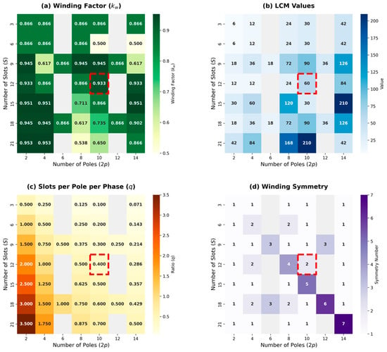
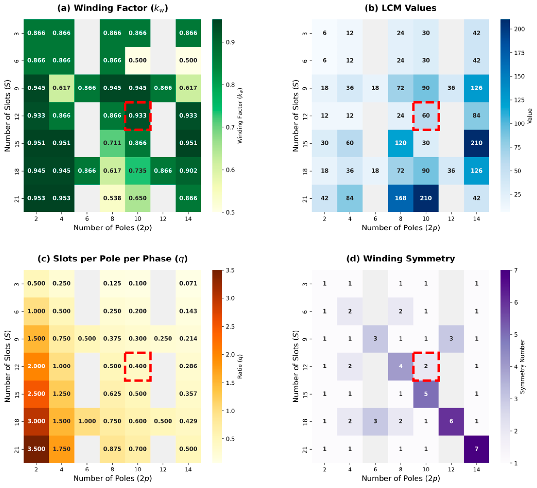
In this study, a 7 × 7 slot–pole screening matrix was constructed, and the winding factor (kw), LCM value, slots per pole per phase (q), and winding symmetry number were calculated for each combination. The obtained decision matrices are presented in Figure 1. In the figure, the selected 12-slot/10-pole combination is highlighted with a red dashed box, while gray cells indicate infeasible or unbalanced winding combinations. Based on these screening results, the 12-slot/10-pole combination was selected since it provides a high winding factor (kw = 0.933), a slots-per-pole-per-phase value of q = 0.4, a sufficient winding symmetry number of 2, and a high LCM value of 60. These characteristics indicate that the selected configuration is suitable for achieving low cogging torque and favorable electromagnetic performance.
Figure 1.
Comparative analysis of various slot–pole combinations based on electromagnetic and winding topology criteria: (a) winding factor (kw), (b) LCM values, (c) slots per pole per phase (q), and (d) winding symmetry. The selected 12-slot/10-pole combination is highlighted with a red dashed box. Gray cells indicate infeasible or unbalanced winding combinations.
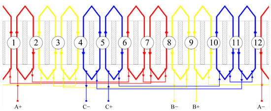
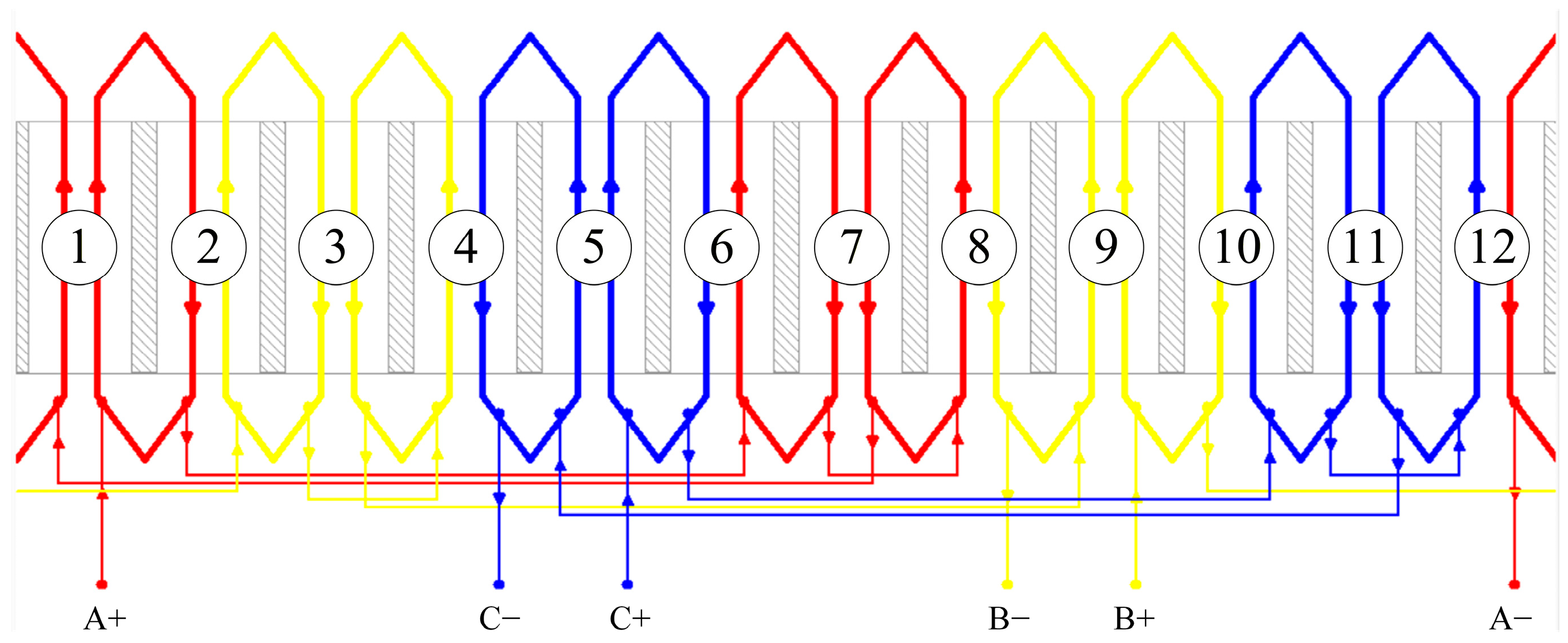
For the selected configuration, a concentrated winding topology was adopted. This topology offers an advantage in limiting copper losses by enabling shorter end-winding lengths. The winding layout and coil arrangement used in the motor are shown in Figure 2.
Figure 2.
Stator winding layout and phase distribution for the 12-slot/10-pole concentrated-winding IPMSM. The red, yellow, and blue lines represent phases A, B, and C, respectively; the numbers 1–12 denote the stator slot numbers; and the A, B, and C labels with “+” and “−” signs indicate the corresponding phase terminals, while the arrows show the current directions.
2.3. Electromagnetic Loss Modeling
To accurately predict the thermal behavior of the motor, the loss components obtained from electromagnetic analyses must be modeled in detail. The temperature rise in electrical machines is directly associated with the underlying loss mechanisms. Therefore, before performing the numerical thermal analysis, copper losses, core losses, magnet losses, and mechanical losses were evaluated separately. The total loss power can be expressed as follows:
where PCu, PFe, PPM, and Pmech represent the copper losses, core losses, magnet losses, and mechanical losses, respectively.
The copper losses generated in the stator windings were calculated based on the phase current and phase resistance. For the three-phase structure, the copper loss can be expressed as follows:
where Irms denotes the root-mean-square value of the phase current, and R(T) represents the temperature-dependent phase resistance. The phase resistance depends not only on the conductor cross-sectional area and the number of turns, but also on the end-winding length. In the copper loss calculation, the total phase resistance was used. This resistance includes both the active conductor length inside the stator slots and the end-winding length. Therefore, the calculated copper loss accounts for the contributions of both the central winding and end-winding regions. In the thermal model, the total copper loss was assigned to the winding regions as volumetric heat generation.
The core losses generated in the stator and rotor lamination stacks were evaluated as the sum of hysteresis, eddy-current, and excess loss components. In this context, the core loss was expressed as a function of frequency and maximum magnetic flux density using the extended Steinmetz equation:
where Kh, Kc, and Ke denote the hysteresis loss coefficient, eddy-current loss coefficient, and excess loss coefficient, respectively. In addition, Bmax denotes the maximum magnetic flux density, and f denotes the electrical frequency. The first term in the equation represents the hysteresis loss, the second term represents the eddy-current loss, and the third term corresponds to the excess loss arising from the dynamic magnetic behavior of the material.
The Kh, Kc, and Ke coefficients used in the core loss model were determined in Siemens Simcenter SPEED software (Product Version 2020.3.1) based on the material properties of the M250-50A electrical steel used in the stator and rotor cores. These coefficients represent the loss characteristics of the material as a function of frequency and magnetic flux density and were directly used in the numerical analyses.
The losses generated in the rotor magnets arise from eddy currents induced by harmonic magnetic field components. In a spoke-type rotor topology, the geometric arrangement of the magnets and the magnetic field distribution directly affect the level of these losses. In this study, N30SH-grade NdFeB was used as the rotor magnet material, and the magnet losses were evaluated within the electromagnetic analyses and included in the total loss calculation.
Mechanical and additional losses include bearing friction, windage, and other residual loss components that are not explicitly included in the copper, core, and magnet loss terms. In this study, copper, core, and magnet losses were obtained from the electromagnetic analyses, while the remaining loss contribution was assigned to mechanical and additional losses based on the overall loss balance. Therefore, this term was included in the total loss distribution given in Table 2.
Table 2.
Loss distribution of the designed IPMSM under nominal operating conditions.
The loss components obtained under nominal operating conditions are presented in Table 2. The loss distribution shows that the largest contribution comes from the copper losses generated in the stator windings, followed by the stator core losses. Due to the high operating speed, mechanical losses also constitute a noticeable component of the total loss. These calculated loss components were subsequently assigned to the corresponding motor regions as volumetric heat sources in the finite element thermal analysis.
2.4. Thermal Modeling
A numerical thermal analysis based on the finite element method (FEM) was carried out to accurately predict the thermal behavior of the motor. The thermal analyses were performed in ANSYS Workbench R19.2 using the Steady-State Thermal Analysis approach.
In the thermal model, the loss components obtained from the electromagnetic analyses were assigned to the corresponding motor regions as volumetric heat sources. In this context, the calculated losses for the stator core, rotor core, stator windings, and rotor magnets were directly applied to the model. The loss distribution was determined under nominal operating conditions and was assumed to be a constant heat generation input in the model. The numerical thermal model was defined by assigning the electromagnetic loss components to the corresponding solid domains, specifying material-dependent thermal properties, applying natural convection on the external motor surfaces, and solving the steady-state heat conduction problem under nominal operating conditions.
Under steady-state conditions, heat conduction is expressed by the following differential equation:
where k represents the thermal conductivity, T denotes the temperature distribution, and qv represents the volumetric heat generation. Under three-dimensional steady-state conditions, direction-dependent heat conduction and convection effects can be expressed as follows
where kxx, kyy, and kzz denote the thermal conductivity coefficients in the x, y, and z directions, respectively. The h(T − Tamb) term in the equation represents the heat transfer from the motor surfaces to the ambient environment through convection. This formulation incorporates both direction-dependent heat conduction arising from the multi-material structure of the motor and the effect of external convective heat transfer.
The motor structure was modeled by considering the different material regions. In the thermal model, the stator core, rotor core, windings, magnets, shaft, motor covers, and insulation regions were defined as separate domains. The material properties used in the thermal analysis are given in Table 3.
Table 3.
Material properties used in the thermal analysis.
For the outer surfaces of the motor, a natural convection boundary condition was applied. In this study, no forced cooling was used, and the convective heat transfer coefficient was selected as h = 14 W/m2K, which is within the typical range reported for natural convection from external surfaces to air [33]. The ambient temperature was defined as Tamb = 22 °C. Since the motor does not include any forced cooling mechanism, heat transfer occurs mainly through conduction and natural convection. Radiation effects were neglected. In the thermal finite element model, the calculated loss components listed in Table 2 were assigned to their corresponding physical domains as volumetric heat sources. Accordingly, the copper loss was applied to the stator winding volume, the stator core loss to the stator lamination stack, the rotor core loss to the rotor lamination stack, and the magnet loss to the permanent magnet volumes. The steady-state thermal analysis was solved using the Mechanical APDL solver within ANSYS Workbench. The contact interfaces between adjacent solid domains were defined as bonded contacts; therefore, no additional thermal contact resistance was introduced at these interfaces. Consequently, thermal contact resistances associated with manufacturing-related surface conditions, such as small air gaps or imperfect surface contact, were not explicitly considered in the model. The natural convection boundary conditions described above were applied separately to the front cover, rear cover, and other external motor surfaces exposed to ambient air.
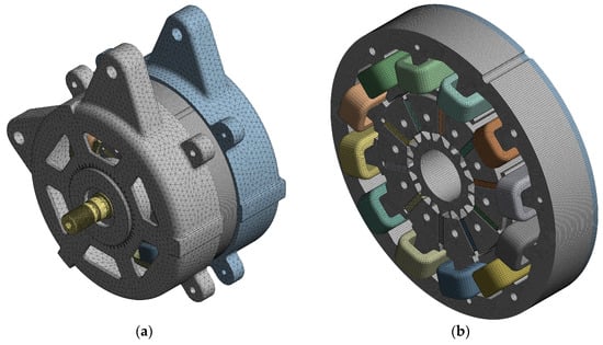
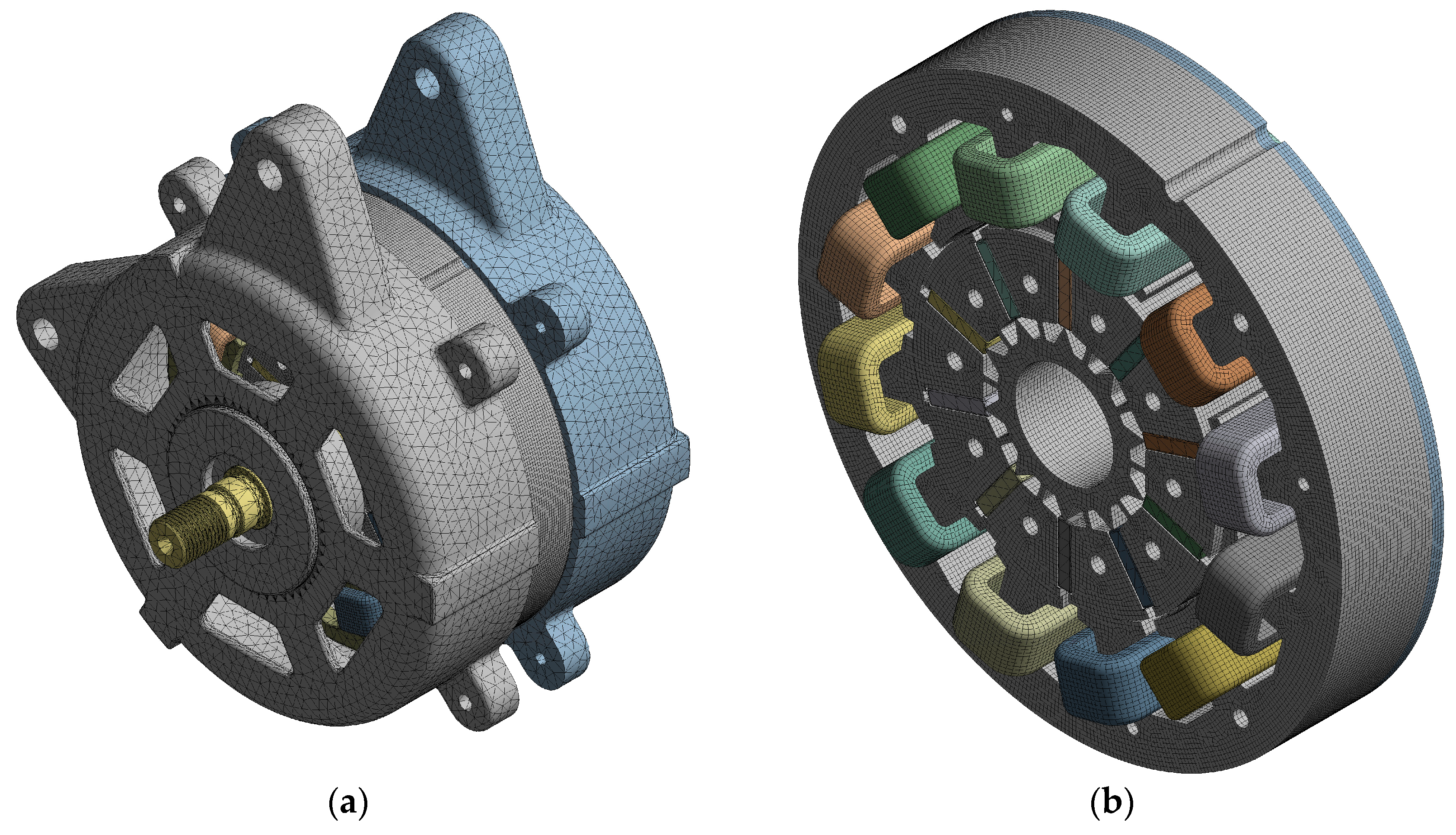
During the construction of the finite element model, a finer mesh was used, particularly in regions where high heat generation was expected, such as the windings and magnets. This approach enabled the temperature gradients to be calculated more accurately. The finite element mesh used in the thermal analysis is shown in Figure 3. Figure 3a presents the mesh model of the external motor structure, while Figure 3b shows the internal mesh including the stator, rotor, and winding regions. The generated mesh consists of a total of 2,432,467 nodes and 634,762 elements.
Figure 3.
Finite element mesh used in the thermal analysis: (a) external mesh of the motor assembly and (b) internal mesh of the stator, rotor, and winding regions.
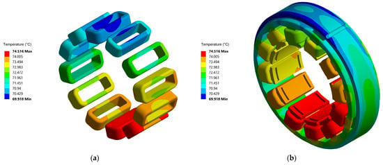
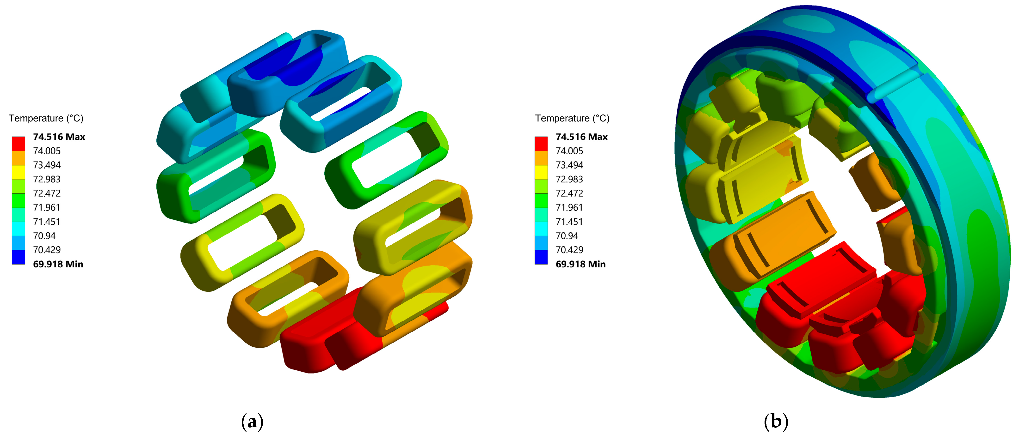
The developed thermal model was used to determine the temperature distribution of the designed and manufactured IPMSM, and the results were subsequently compared with experimental measurements. Since the physical prototype was tested under continuous-duty operation until full thermal saturation was achieved, the steady-state finite element model provides a valid representation of these maximum temperature stabilization limits. The steady-state thermal behavior of the IPMSM under passive cooling conditions is presented in Figure 4. According to the analysis results, the maximum temperature in the stator windings was calculated to be approximately 75 °C. The temperature distribution indicates that the windings located in the lower part of the motor reached a temperature approximately 4.6 °C higher than those in the upper regions. This difference is considered to be associated with the structural asymmetry of the motor housing. The mounting lugs and extended housing surface located in the upper part of the motor increase the total heat transfer area and thereby improve the passive cooling effect. In contrast, the more limited heat transfer surface in the lower region leads to a local temperature increase.
Figure 4.
Steady-state thermal analysis results: (a) temperature distribution in the stator windings and (b) temperature distribution in the stator–winding region.
When the temperature distribution including both the stator and winding regions is examined, it can be observed that the heat generated in the windings is transferred to the stator core through conduction. In addition, geometric variations in the housing, particularly around the connection points and regions with thickness variations, affect the local thermal resistance. Under the defined natural convection coefficient, the temperature at the outer stator surface decreases to approximately 63.5 °C. This result indicates that the housing design provides a suitable thermal distribution under passive cooling conditions. Overall, the obtained results support the applicability of the passive cooling approach for the proposed motor design.
2.5. Mechanical Structural Analysis
Static structural analyses were performed for the rotor and the complete motor assembly to evaluate the mechanical reliability of the designed IPMSM. In the mechanical analyses, particular attention was given to the centrifugal forces acting on the high-speed rotor, the mechanical retention of the magnets, rotor deformation, and the stress distribution that may occur in the motor assembly. Total deformation and equivalent von Mises stress were considered as the main evaluation criteria. The mechanical assessment in this study was limited to static structural finite element analysis. Therefore, the analysis evaluates the stress and deformation behavior of the rotor and complete motor assembly under the defined centrifugal and assembly loading conditions. Modal, vibration, fatigue, and overspeed analyses/tests were beyond the scope of the present study. Further modal, vibration, fatigue, and overspeed analyses will be considered in future work to provide a more comprehensive mechanical reliability assessment.
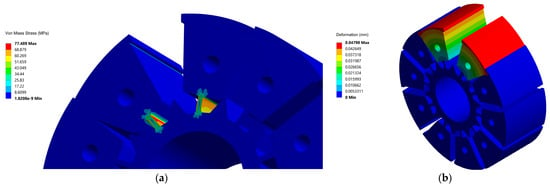
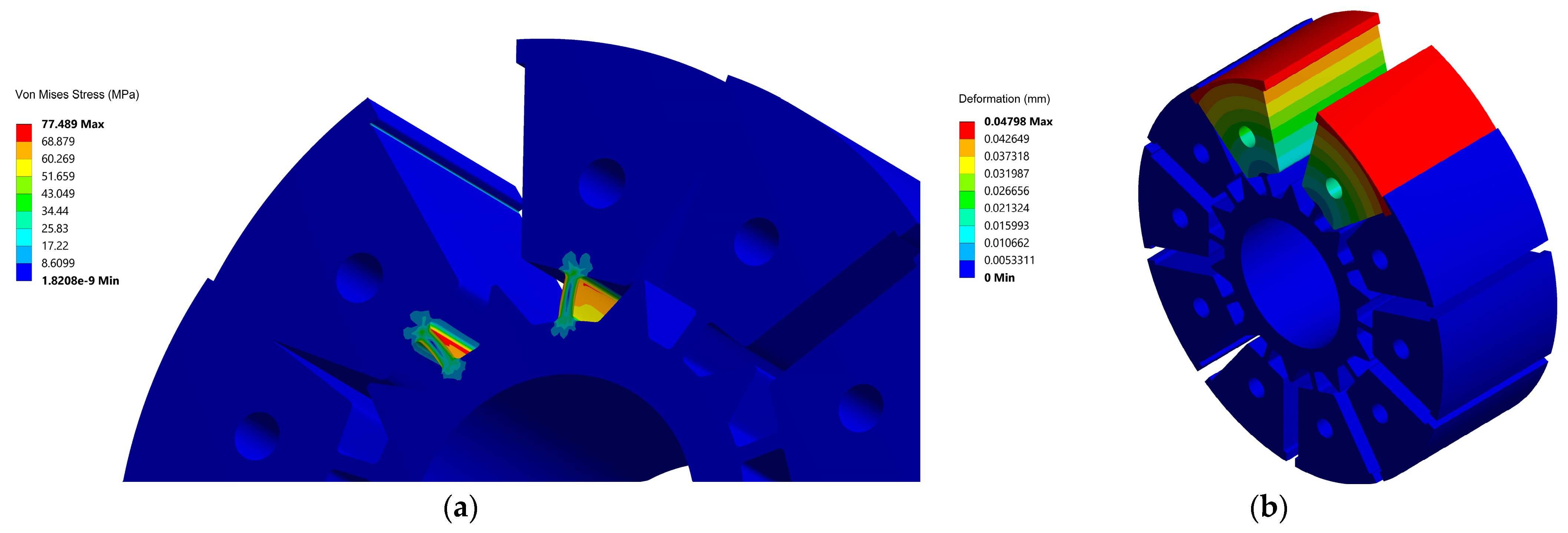
The rotor structure was investigated under centrifugal loading. The static structural analysis was performed in ANSYS Mechanical using the Mechanical APDL solver, with a fixed support boundary condition applied to the inner bore surface of the rotor. The generated mesh for the rotor-level analysis consisted of a total of 552,953 nodes and 121,350 elements. Since the rotor magnets were intended to be removable by design, commonly used adhesive bonding or encapsulation methods were not preferred; instead, the magnets were mechanically constrained within the rotor slots using magnet retaining rings, as described in detail in Section 2.6. Therefore, the end regions of the magnet slots were considered as critical regions where stress concentrations may occur under centrifugal force. In the centrifugal force calculation, the magnet mass, effective radius, and rotor speed were taken into account. In the analysis, the magnet mass, effective radius, and rotor speed were taken as 13.5 g, 40 mm, and 7000 rpm, respectively. Based on these values, the linear velocity was calculated as 29.32 m/s, and the centrifugal force was approximately 290 N. To remain on the conservative side, this value was applied as 300 N in the analyses. The total deformation and equivalent von Mises stress distributions obtained from the rotor centrifugal analysis are shown in Figure 5. The analysis results indicate that the maximum total deformation was 0.04798 mm, while the maximum von Mises stress was 77.489 MPa. The stress was mainly concentrated around the end regions of the magnet slots. When compared with the approximate yield strength of 280 MPa considered for M250-50A electrical steel, the maximum stress generated in the rotor structure remained well below the yield limit. Accordingly, the safety factor (SF) of the rotor was calculated as approximately 3.61 using (9). This result indicates that the rotor structure remains within an adequate mechanical safety margin under the 7000 rpm operating condition.
where σy denotes the yield strength of the material, and σmax represents the maximum equivalent von Mises stress obtained from the structural analysis.
Figure 5.
Rotor centrifugal analysis results: (a) equivalent von Mises stress distribution and (b) total deformation distribution.
In addition to the rotor analysis, a structural analysis was performed on the complete motor assembly to evaluate the overall mechanical behavior of the motor. In this analysis, the front and rear bearing loads, tightening torques of the cover connection bolts, motor mounting bolt torques, and peak motor torque were considered together. The motor was modeled together with the test bench, appropriate connections were defined, and fixed support boundary conditions were applied through the test bench. The numerical model was evaluated using equivalent von Mises stress and total deformation distributions, and the applied loads and boundary conditions were defined separately for the rotor-level centrifugal analysis and the complete motor assembly analysis. The main loads and boundary conditions used in the mechanical analyses are summarized in Table 4.
Table 4.
Main loads and boundary conditions used in the mechanical structural analysis.
For the complete motor assembly analysis, the bearing loads (700 N, Table 4) were applied separately to the front and rear bearing seat surfaces of the covers, the rotor centrifugal force (300 N) was additionally included, and the peak motor torque (6 Nm, Table 4) was applied as a moment on a surface representing the stator lamination stack. The specified bolt tightening torques (Table 4) were converted into equivalent bolt pretension loads and applied at the corresponding bolt locations: 2239 N for each of the four cover connection bolts (4.5 Nm tightening torque) and 6127 N for each of the two motor mounting bolts (25 Nm tightening torque). Contact interfaces between mating components were defined as bonded contacts with automatic contact detection, consistent with the assembled and bolted nature of the structure.
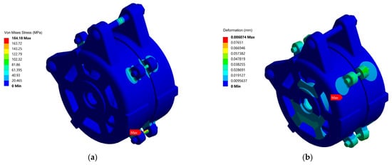
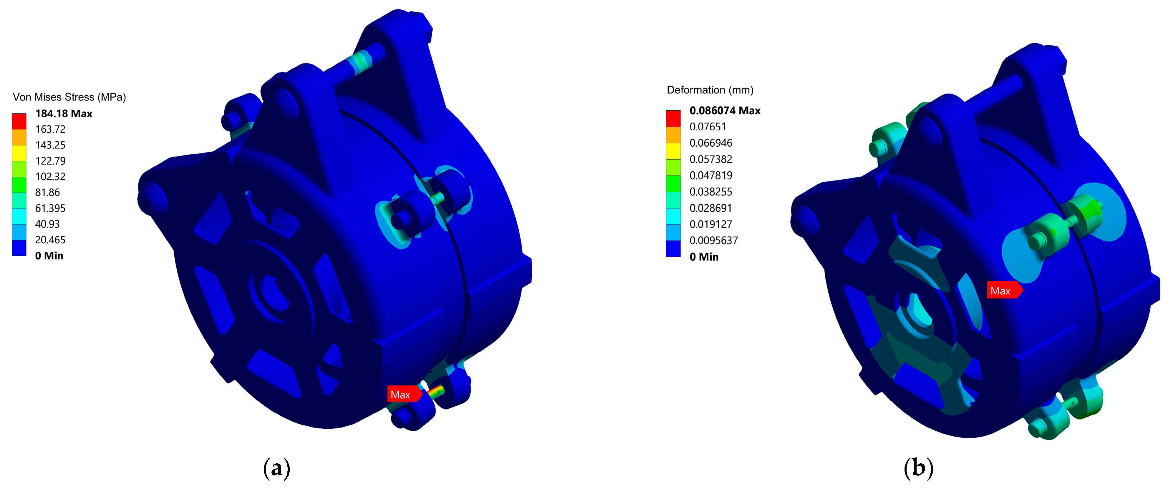
The equivalent von Mises stress and total deformation distributions of the complete motor assembly are shown in Figure 6. As a result of the analysis, the maximum von Mises stress was calculated as 184.18 MPa, while the maximum total deformation was 0.086074 mm. The stress distribution indicates that the high-stress regions mainly occur locally around the bolt connection points and geometric discontinuities. In contrast, lower stress levels were observed across the motor housing and the main load-bearing structure. The total deformation remaining at 0.086074 mm indicates a very limited deformation for the motor assembly. It is considered that this level of deformation would not have an adverse effect on the motor air gap or the overall mechanical alignment. In addition, when the maximum stress value is compared with the yield strength of the materials used, it remains within mechanically acceptable limits. According to the structural FEA results, the maximum deformation affecting the air-gap-facing regions was calculated as 0.0082756 mm for the stator assembly and 0.047961 mm for the rotor structure. Considering the nominal radial air-gap length of the proposed IPMSM as 1 mm, these deformation values correspond to approximately 0.83% and 4.80% of the nominal air-gap length, respectively. Even under the conservative theoretical assumption that both maximum deformations occur at the same radial position and reduce the effective air gap, the combined cumulative deformation is 0.056237 mm, corresponding to approximately 5.62% of the nominal air-gap length. Therefore, the structural deformation remains limited with respect to the available air-gap clearance and is not expected to adversely affect the air-gap alignment or cause mechanical interference between the stator and rotor under the considered operating conditions.
Figure 6.
Mechanical structural analysis results for the motor assembly: (a) equivalent von Mises stress distribution and (b) total deformation distribution.
As a result, the mechanical structural analyses show that the rotor, magnet slots, connection regions, and motor assembly remain within safe limits under the considered operating conditions. The obtained low deformation values indicate that no adverse effect is expected on the air gap or mechanical alignment during high-speed operation. Therefore, in addition to the electromagnetic and thermal analyses, the designed IPMSM is considered to provide a mechanically feasible structure.
In addition to the numerical structural analysis, the rotor assembly was inspected after the motor performance tests to assess the condition of the magnet retention arrangement. During rotor manufacturing, the magnets were mechanically fixed by tightening the front and rear magnet retaining rings with bolts. All bolts were tightened to 4.5 Nm according to the assembly procedure to provide similar preload conditions. After the tests, visual inspections were performed to check for possible magnet displacement, loosening, deformation, or surface damage. In addition, the tightening torques of the connection bolts were re-measured using a calibrated torque wrench and compared with the initial assembly values. No magnet displacement, structural damage, or deformation was observed in the rotor components. Moreover, no measurable reduction in bolt tightening torque was detected after the tests.
2.6. IPMSM Prototype and Structural Components
The prototype of the IPMSM designed in this study was manufactured and used for the experimental validation studies. The structural components of the motor were manufactured in accordance with the geometry considered in the electromagnetic and thermal analyses.
The motor structure consists of the stator core, rotor core, permanent magnets, stator windings, shaft, front and rear covers, and mechanical connection elements. The geometric features and assembly arrangement of these components were realized in accordance with the configuration defined during the design stage.
During prototype manufacturing, special attention was paid to maintaining the uniformity of the rotor–stator air gap, since air-gap nonuniformity may increase vibration, affect electromagnetic performance, and lead to local magnetic saturation. Therefore, the rotor outer diameter and stator inner diameter tolerances were determined by considering the manufacturing capability and the maximum operating speed of the motor. The motor shaft was machined and then precision-ground, particularly at the bearing seat regions and pulley mounting surfaces, to reduce eccentricity and improve the concentricity of the rotating components. For the bearing seat with a diameter of 20 mm, a k5 tolerance was used, corresponding to a tolerance range of +0.002 mm to +0.011 mm. The runout value at the bearing regions was controlled to approximately 0.01 mm.
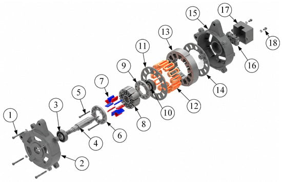
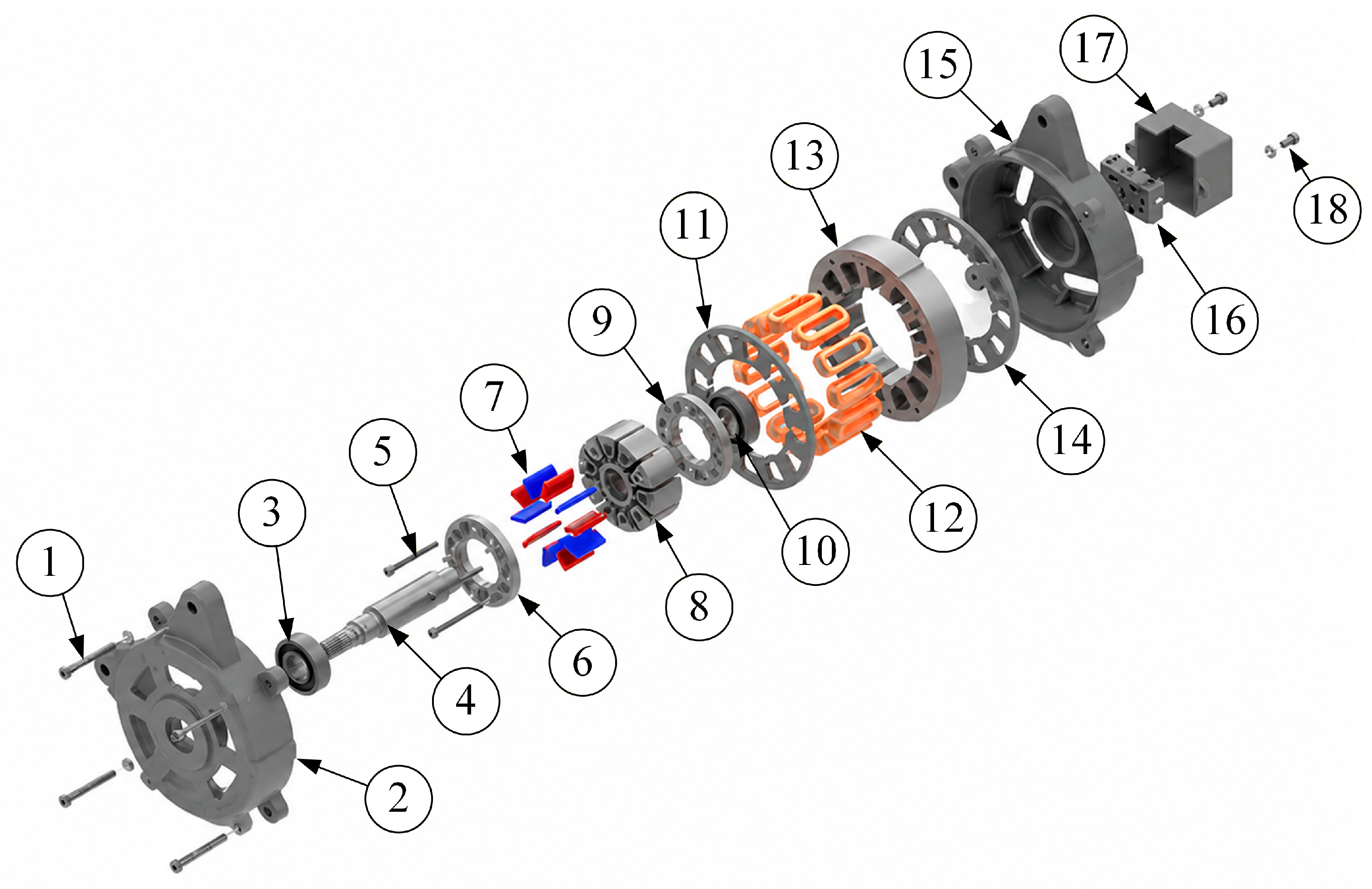
The permanent magnets embedded in the spoke-type rotor were retained without the use of adhesive bonding or resin encapsulation. Instead, the magnets were mechanically constrained within the rotor slots using two dedicated end-rings—a front magnet retaining ring and a rear magnet retaining ring (items 6 and 9 in Figure 7)—positioned at the axial ends of the rotor lamination stack. These retaining rings were fastened to the rotor lamination stack through guide-pin-aligned rotor connection bolts (item 5 in Figure 7), which ensured repeatable angular and axial alignment of the rings during both assembly and disassembly. This configuration allows the magnets to be constrained solely through mechanical clamping, without applying adhesive or encapsulating material directly to the magnet surfaces. As a result, the permanent magnets can, if required, be extracted from the rotor slots without fracturing or surface damage, which is not readily achievable with adhesive-bonded or resin-encapsulated retention methods commonly used in spoke-type rotor designs.
Figure 7.
Exploded assembly view and main components of the designed IPMSM: (1) front cover connection bolts, (2) front cover, (3) front bearing, (4) shaft, (5) rotor connection bolts, (6) front magnet retaining ring, (7) permanent magnets, (8) rotor lamination stack, (9) rear magnet retaining ring, (10) rear bearing, (11) front stator clamping ring, (12) stator windings, (13) stator lamination stack, (14) rear stator clamping ring, (15) rear cover, (16) terminal block, (17) terminal box cover, and (18) terminal connection bolts.
Unlike conventional motor structures, the proposed prototype does not employ a separate external frame. Instead, the front and rear covers are directly seated on the outer diameter of the stator. Since this frameless structure is more sensitive to alignment errors, particular attention was paid to maintaining concentricity and parallelism between the front and rear covers during assembly. The front and rear covers were connected using common connection bolts. The bolts pass through clearance holes on the front cover and are fastened into threaded holes on the rear cover. In this way, both covers were referenced through a common connection system, reducing assembly-related alignment errors.
All connection bolts were tightened using the specified torque value and a controlled tightening sequence. The homogeneous preload generated in the bolts helped preserve the parallelism between the covers and reduced local deformation that could adversely affect rotor–stator alignment.
Dynamic balancing of the rotor assembly was performed to reduce vibration levels and improve operational stability at the maximum operating speed of 7000 rpm. Residual unbalance in the rotor assembly, arising from manufacturing and assembly tolerances, can otherwise increase vibration levels, elevate bearing loads, generate additional noise, and reduce system service life. The balancing procedure was carried out by attaching correction weights at appropriate angular positions on the magnet retaining ring, following determination of the unbalance magnitude and angular location. Based on these measurements, the calculated correction masses were attached to the retaining ring, and the procedure was repeated iteratively until the residual unbalance was reduced to an acceptable level, in accordance with balance quality grade G2.5. The weight-addition method was preferred over material-removal balancing, as it does not require removing material from the rotor components and allows the correction to be re-adjusted if needed—an advantage particularly relevant during prototype development and validation, where multiple balancing iterations are often required.
The stator windings were manually placed into the slots due to the relatively large conductor cross-sectional area. A concentrated winding configuration was applied, and Class H winding insulation was used. Appropriate slot insulation was also used during the winding process to ensure electrical insulation between the conductors and the stator core. As a result of these manufacturing and assembly procedures, the rotor–stator air gap was maintained within acceptable limits, supporting reliable operation and repeatable experimental measurements.
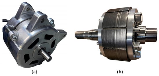
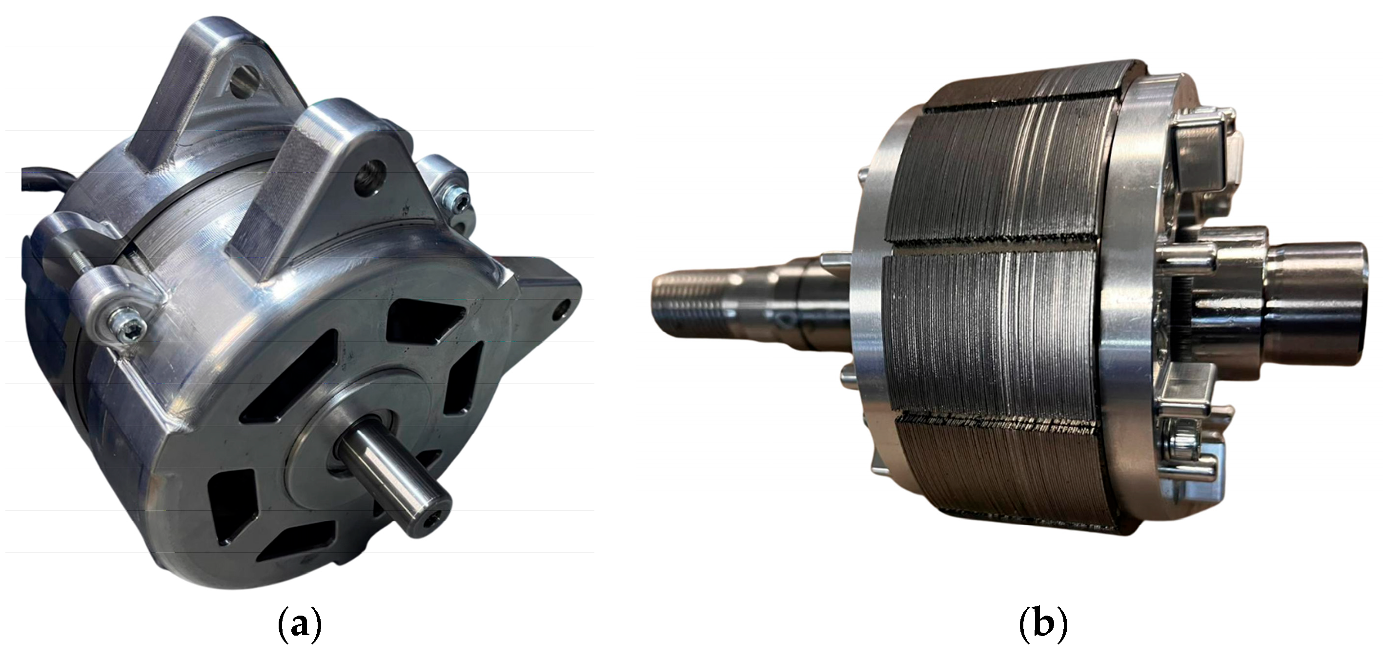
The exploded view of the motor is given in Figure 7. This figure clearly illustrates the main components and assembly structure of the motor. The manufactured prototype of the motor is shown in Figure 8. Within the scope of the experimental studies performed on the prototype, both the electromagnetic performance and thermal behavior of the motor were evaluated.
Figure 8.
Manufactured IPMSM prototype: (a) assembled motor prototype and (b) rotor structure.
3. Results
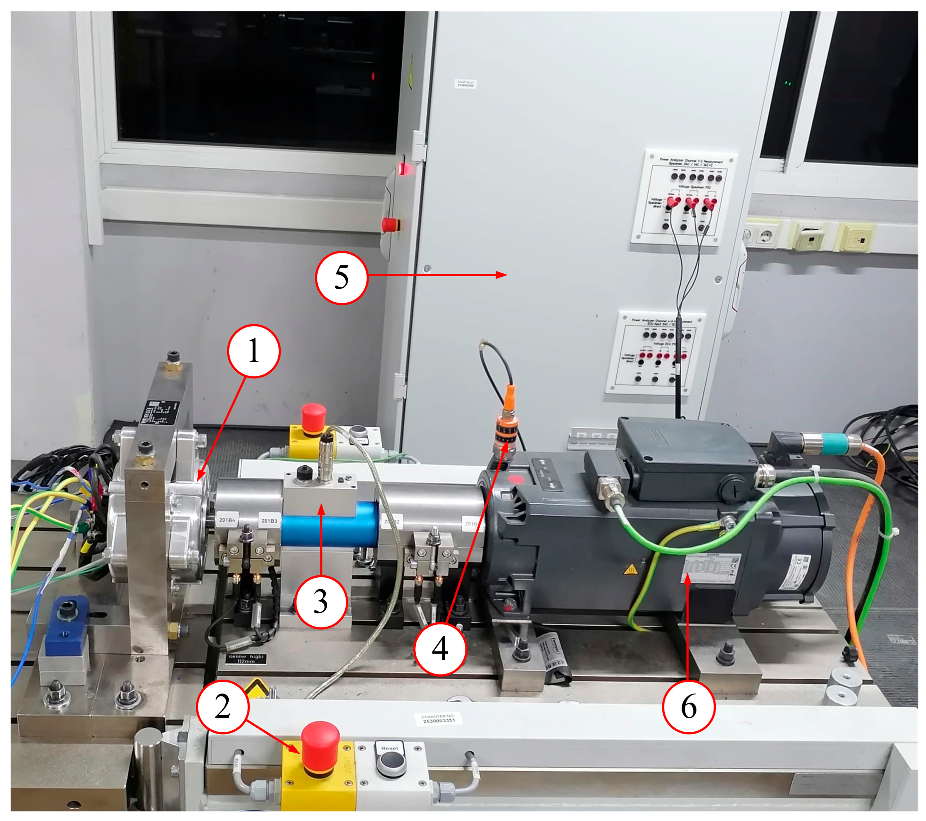
In this section, the experimental and numerical results obtained for the manufactured IPMSM prototype are presented and discussed. The main objective is to evaluate the agreement between the design-stage numerical model and the manufactured prototype under representative operating conditions. For this purpose, the line-to-line back-EMF characteristic, efficiency maps, phase current–torque behavior, output power variation, and thermal behavior under continuous loading were investigated. The electromagnetic performance results were compared with the corresponding simulation results, while the thermal behavior was assessed using both finite element thermal analysis and experimental temperature measurements. The experimental test bench used for the prototype measurements is shown in Figure 9.
Figure 9.
Experimental test bench used for the validation of the manufactured IPMSM prototype: (1) manufactured IPMSM prototype, (2) emergency stop button, (3) torque transducer, (4) vibration transducer, (5) measurement and control panel, and (6) loading machine.
The experimental setup consisted of the manufactured IPMSM prototype, a loading machine, a torque transducer, a vibration transducer, a power analyzer, a thermometer, and a measurement and control panel. The prototype motor was mechanically coupled to the loading machine through a Kistler 4503B torque transducer (Kistler Group, Winterthur, Switzerland), allowing the output torque and rotational speed to be measured during loaded operation. Electrical quantities, including input power, phase current, voltage, and line-to-line back-EMF, were measured using a Yokogawa WT330 power analyzer (Yokogawa Test & Measurement Corporation, Tokyo, Japan). The loading machine was used to apply the required torque levels at different speed points. For the back-EMF test, the prototype motor was driven at different speeds under open-circuit conditions, and the line-to-line voltage was recorded. For the loaded performance tests, the motor was operated at selected speed–torque points using an inverter with field-oriented control (FOC) under speed-controlled operation, and the corresponding phase current, input power, output power, and efficiency values were obtained. The efficiency evaluation was performed in accordance with IEC 60034-2-3 [34] for converter-fed AC motors. The efficiency values were obtained from the measured mechanical output power and electrical input power. The mechanical output power was calculated using the measured torque and rotational speed, while the electrical input power was measured using the Yokogawa WT330 power analyzer. During the thermal test, winding, housing, and ambient temperatures were measured using K-type thermocouples connected to an APPA 52 thermometer (APPA Technology Corporation, New Taipei City, Taiwan) under continuous loading conditions. The winding temperature was measured using K-type thermocouples embedded between the stator windings during the winding process. Additional K-type thermocouples were placed on the outer motor housing surface, and the ambient temperature was also recorded during the test.
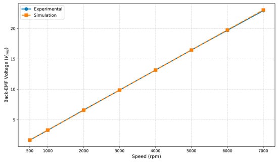
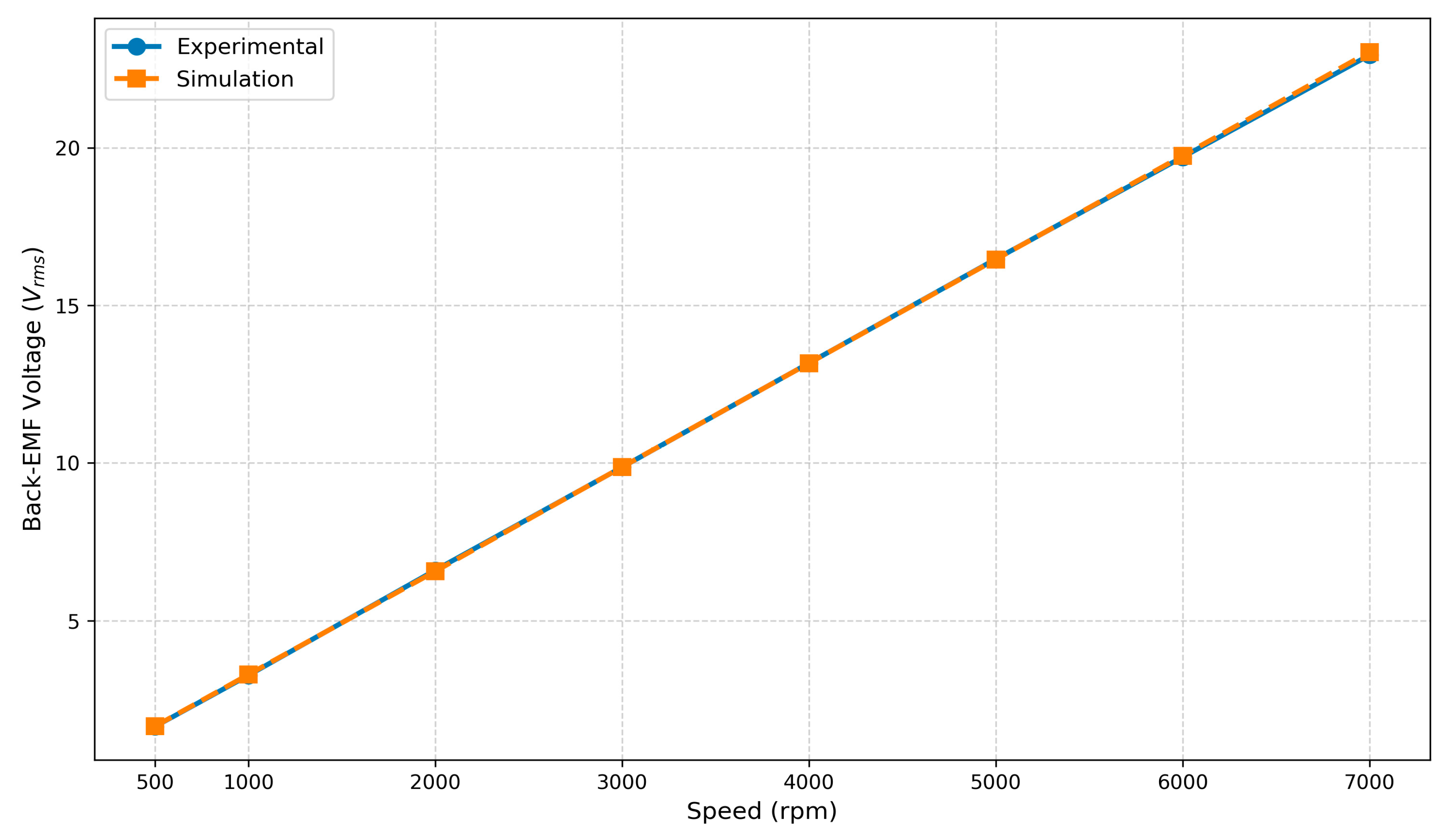
The line-to-line back-EMF characteristic of the manufactured IPMSM prototype was measured at different rotor speeds and compared with the corresponding simulation results. As shown in Figure 10, both the experimental and numerical results exhibit an approximately linear increase with rotor speed, which is consistent with the expected back-EMF behavior of PMSMs. At 7000 rpm, the measured and simulated line-to-line back-EMF values were 22.93 Vrms and 23.04 Vrms, respectively. The corresponding deviation was approximately 0.48%. This close agreement indicates that the flux linkage, winding configuration, and magnet properties used in the numerical model are consistent with those of the manufactured prototype.
Figure 10.
Comparison of experimental and simulated line-to-line back-EMF voltage values at different rotor speeds.
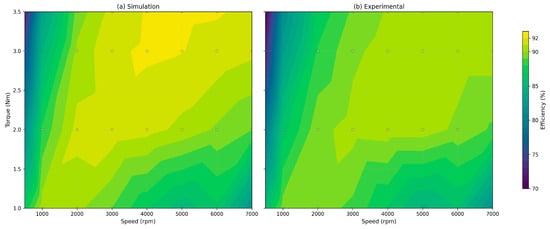
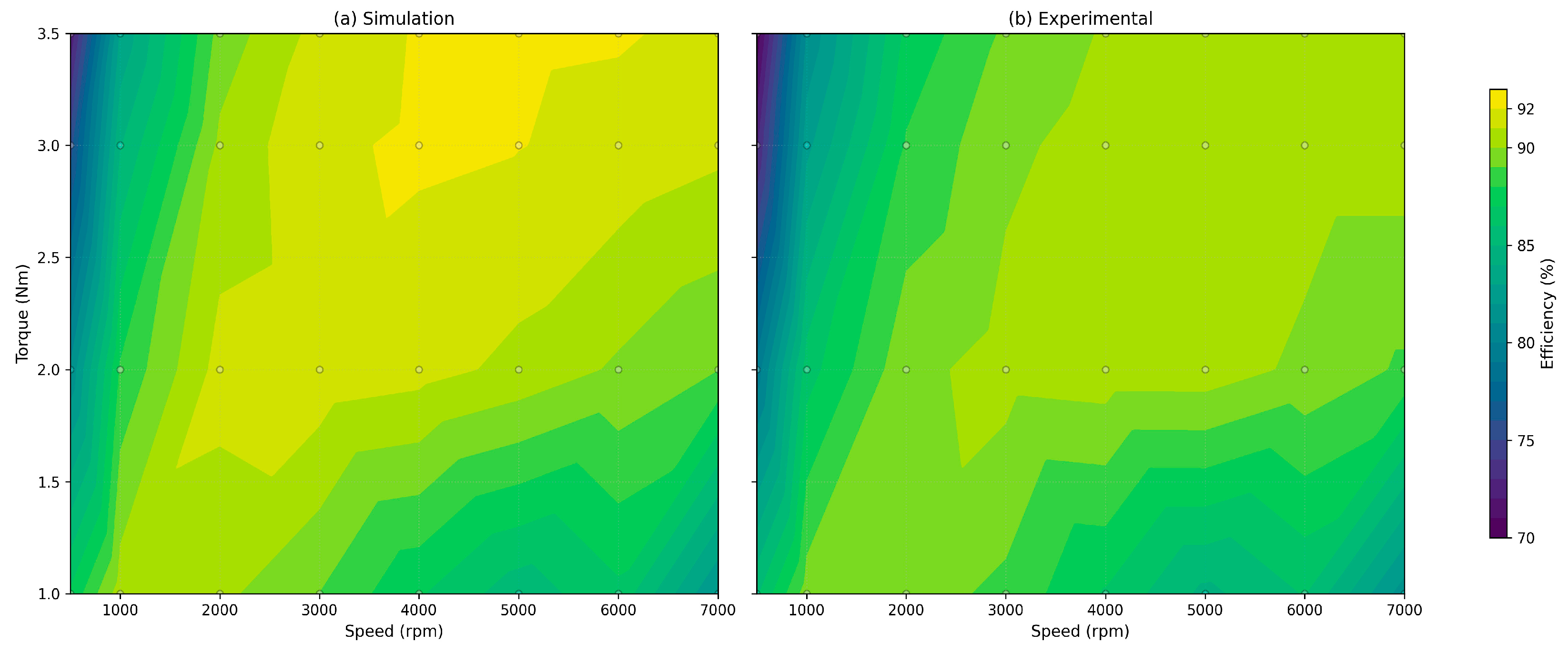
The efficiency values of the manufactured IPMSM prototype were obtained at different speeds and torque operating points to evaluate its loaded performance and were compared with the simulation results. In this context, analyses and experimental measurements were carried out over a speed range of 500–7000 rpm and a torque range of 1–3.5 Nm. The efficiency maps were generated using the obtained operating points and are presented in Figure 11. As shown in this figure, the simulated and experimental efficiency maps exhibit similar overall trends. In both cases, the efficiency remains relatively low in the low-speed region and increases noticeably with increasing speed. Particularly in the medium- and high-speed regions, the motor maintains high efficiency over a wide operating range. The experimental efficiency values were observed to be slightly lower than the simulation results. This difference may be attributed to prototype manufacturing tolerances, mechanical losses, and measurement uncertainties.
Figure 11.
Comparison of efficiency maps obtained under different speed and torque conditions: (a) simulation and (b) experimental results. Open circles indicate the operating points used to generate the maps.
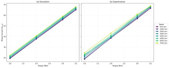
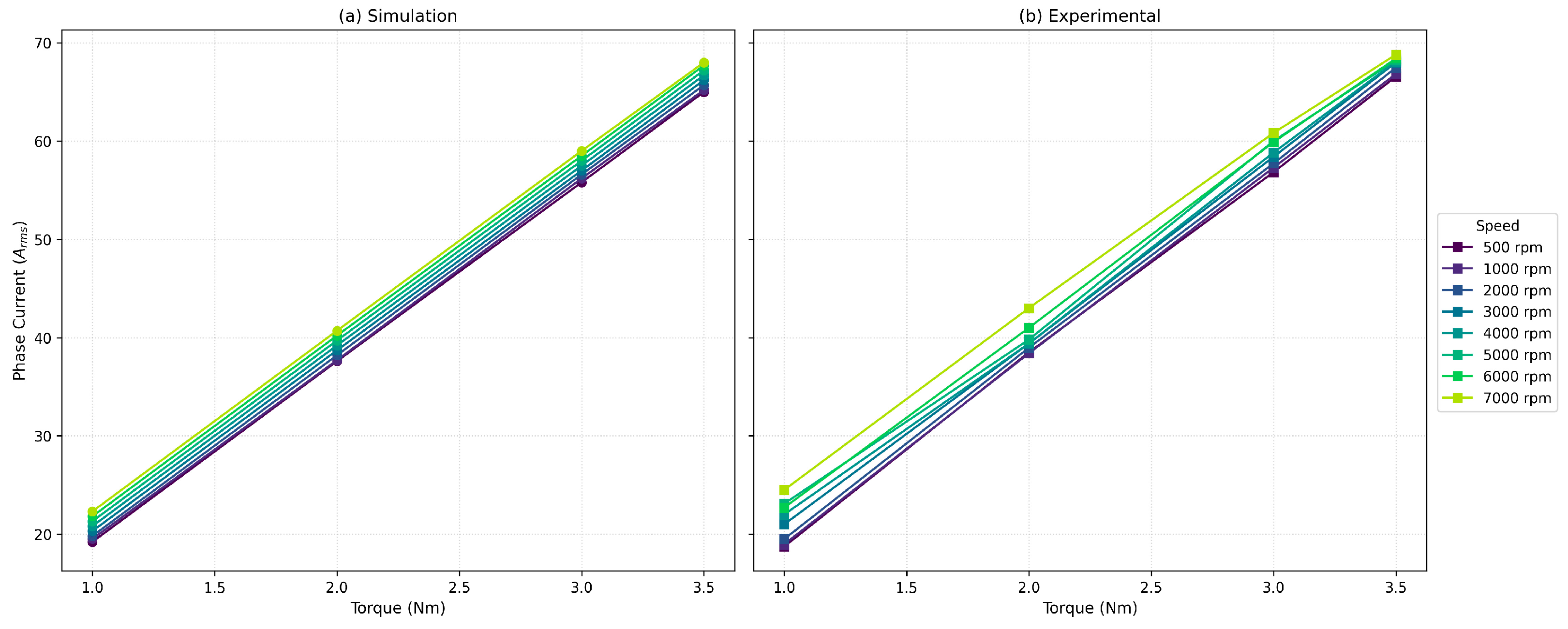
Figure 12 comparatively presents the variation in phase current with torque under different speed conditions using simulation and experimental results. As shown in Figure 12, the phase current increases approximately linearly with increasing torque up to the 3.5 Nm load level. This behavior indicates that the motor exhibits a stable torque production characteristic within the investigated operating range and that no significant magnetic saturation effect occurs. In addition, the close agreement among the curves obtained at different speed levels shows that the current–torque relationship is largely maintained over the tested speed range. However, a limited increase in the required phase current is observed at higher speeds for the same torque value. This difference may be attributed to the combined effects of increased iron losses at high speeds, drive supply conditions, voltage limitations, manufacturing tolerances, and the thermal increase in winding resistance. The generally similar trend between the experimental and simulation results supports that the developed electromagnetic model represents the load-dependent current–torque behavior of the motor with reasonable accuracy.
Figure 12.
Phase current variation with torque under different speed conditions: (a) simulation and (b) experimental results.
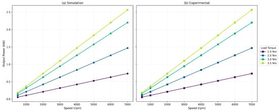
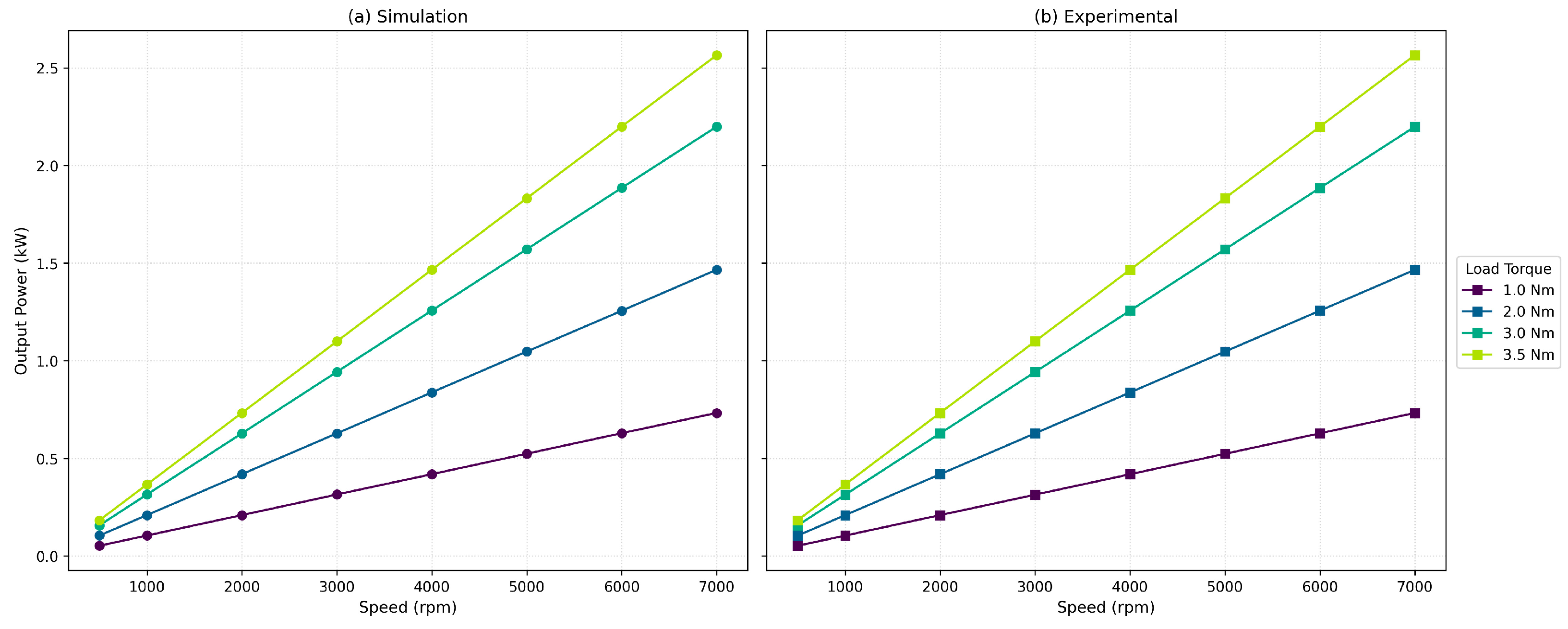
Figure 13 comparatively presents the variation in output power with speed under different load torque conditions using simulation and experimental results. As expected, the output power increases approximately linearly with increasing speed and load torque. The simulation and experimental results show highly similar overall trends, indicating that the loaded power generation characteristic of the prototype motor is consistent with the design model. At the nominal operating point, defined as 3.5 Nm load torque and 7000 rpm, the output power reaches approximately 2.56 kW. This result demonstrates that the designed motor can experimentally achieve the targeted power level.
Figure 13.
Output power variation with speed under different load torque conditions: (a) simulation and (b) experimental results.
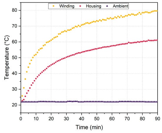
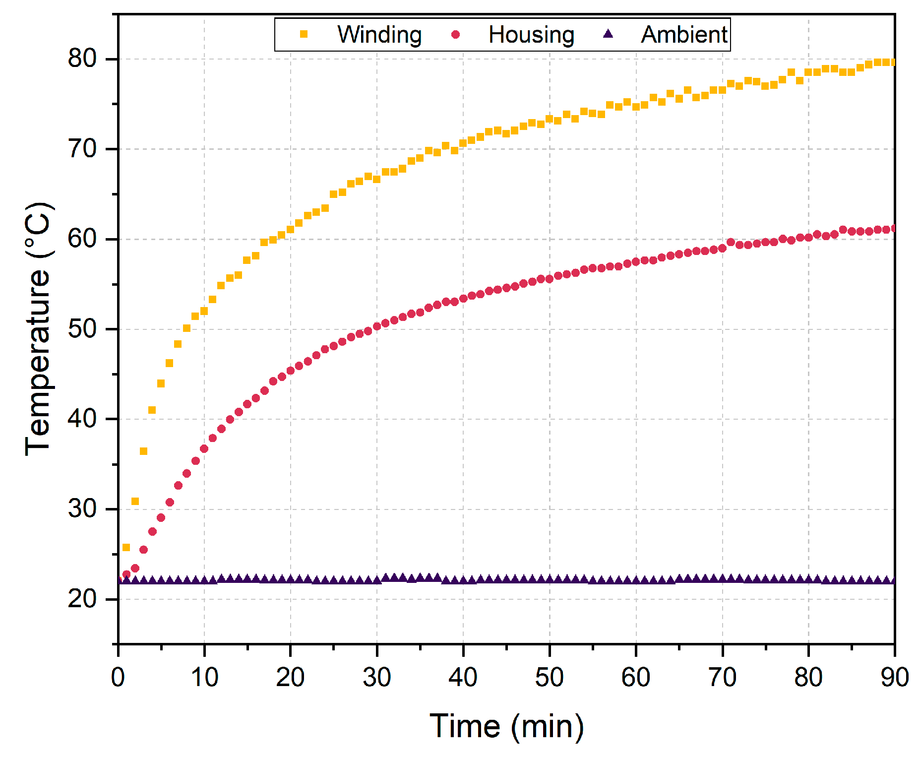
The thermal test results obtained to investigate the thermal behavior of the designed and manufactured IPMSM under continuous loading are presented in Figure 14. During the test, which was initiated at an ambient temperature of approximately 22 °C, the winding and motor housing temperatures were recorded over a 90 min period. The continuous-load experiment was conducted until the temperature variation over time reached a negligible threshold (ΔT/Δt ≈ 0). As indicated by the time-series measurements, the winding temperature approached a stabilized value of 79.6 °C with a variation of less than 0.25 °C during the final ten minutes of the test. Therefore, the final experimental temperature level was used for comparison with the steady-state finite element thermal model. The steady-state thermal analysis predicted a maximum winding temperature of approximately 74.5 °C, while the experimental winding temperature reached approximately 79.6 °C after 90 min. The difference between the numerical and experimental results was approximately 5.1 °C, corresponding to a relative deviation of about 6.4% with respect to the experimental value. This indicates a reasonable correlation between the numerical and experimental thermal results under passive cooling conditions. This deviation may be attributed to thermal contact resistances not explicitly included in the model, local convection variations, manufacturing-related effects, and measurement uncertainty. In accordance with the thermal time-constant behavior, the winding temperature increased more rapidly than the housing temperature due to the higher loss density and lower thermal capacity in the winding region. The outer motor housing temperature stabilized at approximately 61 °C, indicating effective heat transfer from the internal heat-generating regions to the motor housing. The maximum winding temperature remained well below the critical thermal limits of the winding insulation materials, supporting the thermally safe operation of the motor under continuous loading conditions.
Figure 14.
Experimental thermal transient response of the prototype IPMSM: time-dependent temperature variations in the stator windings, motor housing, and ambient under continuous loading conditions.
Table 5 summarizes the experimental and simulation results obtained at the nominal operating point. At 7000 rpm and 3.5 Nm, the measured and simulated values show close agreement for the main performance indicators. The deviations are approximately 1.17% for the phase current, 0.48% for the line-to-line back-EMF, 1.18% for the input power, and 1.20% for the efficiency. The slight efficiency difference of approximately 1.1 percentage points can be attributed to manufacturing tolerances, winding resistance variations, additional mechanical losses, and measurement uncertainties. Overall, the comparison indicates that the developed numerical model represents the manufactured prototype with reasonable accuracy under the nominal operating condition.
Table 5.
Comparison of experimental and simulation performance parameters under nominal operating conditions.
4. Conclusions
This study presented the prototype-level evaluation of a 12-slot/10-pole spoke-type IPMSM developed for compact electric vehicle traction applications. The manufactured motor was investigated in terms of electromagnetic performance, mechanical integrity, and thermal behavior under representative operating conditions.
The experimental back-EMF, efficiency map, phase current–torque, and output power results showed good agreement with the corresponding simulation results. At the nominal operating point of 7000 rpm and 3.5 Nm, the prototype delivered approximately 2.56 kW output power with an experimental efficiency of 90.7%. The small deviations observed between the simulation and experimental results can be attributed to manufacturing tolerances, winding resistance variations, additional mechanical losses, and measurement uncertainties. These findings indicate that the numerical model represents the manufactured prototype with reasonable accuracy under the investigated operating conditions.
The mechanical structural analyses showed that the rotor and complete motor assembly remained within acceptable mechanical limits under high-speed and loading conditions. The rotor safety factor was calculated as approximately 3.61, and the deformation levels obtained for the complete assembly were sufficiently low to avoid adverse effects on the air gap and mechanical alignment. These results support the mechanical feasibility of the proposed IPMSM structure for 7000 rpm operation.
The thermal analysis and experimental thermal test results demonstrated that the prototype can operate safely under passive cooling conditions. The steady-state thermal analysis predicted a maximum winding temperature of approximately 75 °C, while the experimental test showed that the winding temperature reached approximately 80 °C after 90 min of continuous loading. The motor housing temperature remained around 61 °C, indicating effective heat transfer from the internal heat-generating regions to the housing. The measured winding temperature remained below the critical thermal limits of the insulation materials, supporting the thermal suitability of the proposed design.
Overall, the results show that the manufactured IPMSM prototype provides consistent electromagnetic performance, adequate mechanical reliability, and thermally safe operation under the investigated conditions. Future work will focus on extended drive-cycle tests, detailed loss characterization under different thermal states, and further refinement of the prototype design to improve overall efficiency and long-term operating reliability. In addition, since the adopted retaining-ring-based magnet retention mechanism allows non-destructive rotor disassembly, future work will include physically extracting the permanent magnets from the tested prototype and evaluating their potential for recovery and reuse in the motor. Further modal, vibration, fatigue, and overspeed analyses will also be considered to provide a more comprehensive mechanical reliability assessment.
Author Contributions
Conceptualization, H.N., N.S.A. and A.A.; methodology, H.N., N.S.A. and A.A.; validation, H.N., A.Y., N.S.A. and A.A.; formal analysis, H.N., N.S.A. and A.A.; investigation, H.N., A.Y., N.S.A. and A.A.; writing—original draft preparation, H.N. and A.Y.; writing—review and editing, A.Y. and A.O.; visualization, A.Y.; supervision, A.Y. and A.O.; funding acquisition, H.N., N.S.A. and A.A. All authors have read and agreed to the published version of the manuscript.
Funding
This research was funded by the European Union’s Horizon Europe research and innovation programme under the Grant Agreement 101189783.
Data Availability Statement
The original contributions presented in this study are included in the article. Further inquiries can be directed to the corresponding author.
Acknowledgments
The authors would like to thank Volt WEG Group for their valuable support.
Conflicts of Interest
Authors Hayatullah Nory, Nesibe Sibel Akbulut, and Abdurrahman Atila were employed by Volt Weg Group. The remaining authors declare that the research was conducted in the absence of any commercial or financial relationships that could be construed as a potential conflict of interest.
References
- Imam, S.H.; Rind, S.J.; Javed, S.; Jamil, M. New Trends and Challenges in Electric and Hybrid Electric Vehicles: Powertrain Configurations, Traction Motors and Drive Control Techniques. Machines 2026, 14, 489. [Google Scholar] [CrossRef] [Scilit]
- Huynh, T.A.; Hsieh, M.-F. Performance Analysis of Permanent Magnet Motors for Electric Vehicles (EV) Traction Considering Driving Cycles. Energies 2018, 11, 1385. [Google Scholar] [CrossRef] [Scilit]
- Polat, M.; Yildiz, A.; Akinci, R. Performance Analysis and Reduction of Torque Ripple of Axial Flux Permanent Magnet Synchronous Motor Manufactured for Electric Vehicles. IEEE Trans. Magn. 2021, 57, 8106809. [Google Scholar] [CrossRef] [Scilit]
- Yildiz, A.; El, E.; Cakmak, G. Thermal Analysis and Experimental Validation of a Permanent Magnet Synchronous Motor. In Proceedings of the 2026 25th International Symposium INFOTEH-JAHORINA (INFOTEH), East Sarajevo, Bosnia and Herzegovina, 18–20 March 2026; pp. 1–5. [Google Scholar] [CrossRef] [Scilit]
- Ullah, W.; Fatima, M.; Abido, M.A.; Akuru, U.B.; Samkari, H.S.; Allehyani, M.F.; Junejo, A.K. Design Analysis and Comparison of a Novel IPM Synchronous Machine with Minimum Rare-Earth PM Usage for EV Industrial Applications. Machines 2026, 14, 530. [Google Scholar] [CrossRef] [Scilit]
- Cheng, Y.; Ding, L.; Zhao, T.; Cui, S. Design and Optimization of Electric Vehicle Traction Motor Considering Rotor Topology and Manufacturing Uncertainty. IEEE Trans. Ind. Electron. 2024, 71, 5034–5044. [Google Scholar] [CrossRef] [Scilit]
- Kolsi, H.; Benhadj, N.; Guesmi, T.; Marouani, I.; Alshammari, B.M.; Alsaif, H.; Alqunun, K.; Neji, R. Optimal Design of a PMSM for Electric Vehicle Using Chaotic Particle Swarm Optimization. IEEE Access 2024, 12, 170273–170294. [Google Scholar] [CrossRef] [Scilit]
- Lee, J.-H.; Kim, W.-J.; Jung, S.-Y. Robust Explorative Particle Swarm Optimization for Optimal Design of EV Traction Motor. Processes 2021, 9, 2000. [Google Scholar] [CrossRef] [Scilit]
- Niu, L.; Zhang, M. Rotor Topology Optimization and Electromagnetic Performance Analysis of Interior Permanent Magnet Synchronous Motors for Electric Vehicle Applications. J. Eng. 2023, 2023, e212240. [Google Scholar] [CrossRef] [Scilit]
- Lupu, E.-D.; Tabacu, Ș.L. System-Level Comparative Assessment of PMSM Rotor Topologies in Battery Electric Vehicles Under the WLTP Driving Cycle. Vehicles 2026, 8, 66. [Google Scholar] [CrossRef] [Scilit]
- Geng, W.; Wang, Y.; Wang, J.; Hou, J.; Guo, J.; Zhang, Z. Comparative Study of Yokeless Stator Axial-Flux PM Machines Having Fractional Slot Concentrated and Integral Slot Distributed Windings for Electric Vehicle Traction Applications. IEEE Trans. Ind. Electron. 2023, 70, 155–166. [Google Scholar] [CrossRef] [Scilit]
- Zhou, C.; Huang, X.; Li, Z.; Cao, W. Design Consideration of Fractional Slot Concentrated Winding Interior Permanent Magnet Synchronous Motor for EV and HEV Applications. IEEE Access 2021, 9, 64116–64126. [Google Scholar] [CrossRef] [Scilit]
- Liu, S.; Huang, J. Multi-Objective Optimization of a Spoke-Type Permanent Magnet Motor with Fractional-Slot Concentrated Windings for EVs. COMPEL Int. J. Comput. Math. Electr. Electron. Eng. 2021, 40, 561–578. [Google Scholar] [CrossRef] [Scilit]
- Jang, H.; Kim, H.; Liu, H.-C.; Lee, H.-J.; Lee, J. Investigation on the Torque Ripple Reduction Method of a Hybrid Electric Vehicle Motor. Energies 2021, 14, 1413. [Google Scholar] [CrossRef] [Scilit]
- Zhang, G.; Yu, W.; Hua, W.; Cao, R.; Qiu, H.; Guo, A. The Design and Optimization of an Interior, Permanent Magnet Synchronous Machine Applied in an Electric Traction Vehicle Requiring a Low Torque Ripple. Appl. Sci. 2019, 9, 3634. [Google Scholar] [CrossRef] [Scilit]
- Wang, D.; Peng, C.; Li, J.; Wang, C. Comparison and Experimental Verification of Different Approaches to Suppress Torque Ripple and Vibrations of Interior Permanent Magnet Synchronous Motor for EV. IEEE Trans. Ind. Electron. 2023, 70, 2209–2220. [Google Scholar] [CrossRef] [Scilit]
- Chand, D.S.R.S.; Gunabalan, R.; Inayathullaah, M.A. Design and Performance Analysis of Inner-Rotor IPM PMSMs for Cogging Torque and Ripple Reduction in EV Applications. Results Eng. 2026, 30, 110269. [Google Scholar] [CrossRef] [Scilit]
- Ravichandran, V.; Subramanium, M.; Joshua Stephen Chellakumar, I.J.L. Reduction of Torque Ripple in Permanent Magnet Synchronous Motors for Electric Vehicles Using Enhanced Dwarf Mongoose Optimisation and a Supervised Attention-Based Multi-Scale Temporal Convolutional Network. IET Electr. Power Appl. 2026, 20, e70168. [Google Scholar] [CrossRef] [Scilit]
- Yahia, T.; Elbarbary, Z.M.S.; Alqahtani, S.A.; Ahmed, A.A. Event-Triggered Extension of Duty-Ratio-Based MPDSC with Field Weakening for PMSM Drives in EV Applications. Machines 2026, 14, 137. [Google Scholar] [CrossRef] [Scilit]
- Alwaqfi, S.; Alzayed, M.; Chaoui, H. Flux-Weakening Control Methods for Permanent Magnet Synchronous Machines in Electric Vehicles at High Speed. Electronics 2025, 14, 3779. [Google Scholar] [CrossRef] [Scilit]
- Wang, Y.; Wu, J.; Guo, Z.; Xie, C.; Liu, J.; Jin, X. Flux-Weakening Fuzzy Adaptive ST-SMO Sensorless Control Algorithm for PMSM in EV. J. Supercomput. 2022, 78, 10930–10949. [Google Scholar] [CrossRef] [Scilit]
- Zhou, Y.; Zhang, S.; Hu, Y.; Jiao, Y.; Zhao, Y. Torque Performance Optimization for PMSM Drives in Flux-Weakening Region With Sliding-Mode-Based Disturbance Observer. IEEE Trans. Power Electron. 2026, 41, 12997–13011. [Google Scholar] [CrossRef] [Scilit]
- Ibrahim, M.; Järg, O.; Seppago, R.; Rassõlkin, A. Performance Optimization of a High-Speed Permanent Magnet Synchronous Motor Drive System for Formula Electric Vehicle Application. Sensors 2025, 25, 3156. [Google Scholar] [CrossRef] [Scilit] [PubMed]
- Chiu, C.-C.; Mao, W.-L.; Tai, F.-C. A Stability-Aware Adaptive Fractional-Order Speed Control Framework for IPMSM Electric Vehicles in Field-Weakening Operation. Energies 2026, 19, 1326. [Google Scholar] [CrossRef] [Scilit]
- Shewalkar, A.G.; Dhoble, A.S.; Kumar, V.; Bhakre, S.S. Experimental and Numerical Thermal Analysis of a 1.2-kW Air-Cooled PMSM Motor Used in Electric Vehicle. J. Therm. Anal. Calorim. 2025, 150, 12501–12511. [Google Scholar] [CrossRef] [Scilit]
- Zhu, G.; Jia, N.; Li, L.; Liu, T.; Xue, M.; Li, M. Cooling System Design Optimization of a High Power Density PM Traction Motor for Electric Vehicle Applications. J. Electr. Eng. Technol. 2021, 16, 3061–3068. [Google Scholar] [CrossRef] [Scilit]
- Park, J.; An, J.; Han, K.; Choi, H.-S.; Seouk Park, I. Enhancement of Cooling Performance in Traction Motor of Electric Vehicle Using Direct Slot Cooling Method. Appl. Therm. Eng. 2022, 217, 119082. [Google Scholar] [CrossRef] [Scilit]
- Karnavas, Y.L.; Chasiotis, I.D.; Peponakis, E.L. Cooling System Design and Thermal Analysis of an Electric Vehicle’s in-Wheel PMSM. In Proceedings of the 2016 XXII International Conference on Electrical Machines (ICEM), Lausanne, Switzerland, 4–7 September 2016; pp. 1439–1445. [Google Scholar]
- Liang, D.; Zhu, Z.Q.; Dey, A. High-Fidelity Lumped-Parameter Thermal Models for Assessing Cooling Techniques of PMSMs in EV Applications. CES Trans. Electr. Mach. Syst. 2025, 9, 1–14. [Google Scholar] [CrossRef] [Scilit]
- Su, Y.; Zhao, J.; An, G.; Jin, W.; Li, S.; Nie, Y.; Xu, G. An Overview of Recent Advances in the Online Temperature Estimation of PMSM in Electric Vehicle Applications. Electronics 2026, 15, 1249. [Google Scholar] [CrossRef] [Scilit]
- Usca-Gomez, H.G.; Puma-Benavides, D.S.; Zambrano-Leon, V.D.; Castillo-Díaz, R.; Quinga-Morales, M.I.; Solís-Santamaria, J.M.; Llanes-Cedeño, E.A. A Review and Case of Study of Cooling Methods: Integrating Modeling, Simulation, and Thermal Analysis for a Model Based on a Commercial Electric Permanent Magnet Synchronous Motor. World Electr. Veh. J. 2025, 16, 437. [Google Scholar] [CrossRef] [Scilit]
- Nory, H.; Yildiz, A.; Aksun, S.; Aksoy, C. Design and Analysis of an IE6 Hyper-Efficiency Permanent Magnet Synchronous Motor for Electric Vehicle Applications. Energies 2025, 18, 4684. [Google Scholar] [CrossRef] [Scilit]
- Tong, W. Mechanical Design of Electric Motors; CRC Press: Boca Raton, FL, USA, 2014; ISBN 978-0-429-14502-05. [Google Scholar]
- IEC 60034-2-3; Rotating Electrical Machines—Part 2-3: Specific Test Methods for Determining Losses and Efficiency of Converter-Fed AC Motors. International Electrotechnical Commission (IEC): Geneva, Switzerland, 2024.

Disclaimer/Publisher’s Note: The statements, opinions and data contained in all publications are solely those of the individual author(s) and contributor(s) and not of MDPI and/or the editor(s). MDPI and/or the editor(s) disclaim responsibility for any injury to people or property resulting from any ideas, methods, instructions or products referred to in the content. |
© 2026 by the authors. Licensee MDPI, Basel, Switzerland. This article is an open access article distributed under the terms and conditions of the Creative Commons Attribution (CC BY) license.