


Abstract
Electric power steering (EPS) systems have become the dominant steering solution in modern vehicles due to their advantages in energy efficiency and driving convenience. Among EPS configurations, rack-type EPS(R-EPS) is widely adopted in mid-to-large vehicles for its direct and responsive steering characteristics. However, conventional slotted motors used in R-EPS suffer from cogging torque and torque ripple caused by periodic reluctance variation in the stator tooth structure, resulting in vibration and noise directly perceived by the driver. This article proposes a slotless Surface Permanent Magnet Synchronous Motor (SPMSM) employing a Bar-Type magnet with a double-bridge rotor structure for R-EPS applications. By eliminating stator teeth, the proposed design achieves a uniform reluctance distribution during rotor rotation, theoretically reducing cogging torque to zero. The absence of stator tooth magnetic saturation further enables the use of high-remanence permanent magnets, improving gravimetric power density and enabling motor miniaturization. The proposed motor was designed and verified through finite element analysis (FEA). Compared to the conventional Arc-Type motor, the optimized design achieves a torque ripple reduction of 64.7% (from 5.07% to 1.79%) through Bar-Type magnet shaping combined with a 5 mm edge filet. The optimized design achieved an output power of 359.9 W, a gravimetric power density of 276.85 W/kg based on an active part weight of 1.30 kg, and a structural safety factor of 1146, demonstrating the effectiveness of the proposed double-bridge slotless motor for R-EPS applications.
1. Introduction
Electric power steering (EPS) systems have become the dominant steering solution in modern vehicles, replacing conventional hydraulic systems owing to their advantages in energy efficiency and compatibility with advanced driver-assistance systems [1,2]. Among EPS configurations, rack-type EPS (R-EPS) is widely adopted in mid-to-large class vehicles due to its direct mechanical linkage between the assist motor and the steering rack, which enables high steering force with precise responsiveness [3]. Because this direct-drive architecture transmits motor-side torque disturbances almost unattenuated to the steering wheel, the motors used in R-EPS must satisfy stringent requirements for low cogging torque, low torque ripple, and high gravimetric power density.
Surface-mounted permanent magnet synchronous motors (SPMSM) are the preferred topology for R-EPS applications owing to their high torque-to-weight ratio and ease of control [4,5,6]. However, conventional slotted SPMSM designs inherently generate cogging torque and torque ripple due to the periodic reluctance variation caused by the stator tooth-slot structure [7]. Various mitigation techniques have been proposed, including stator skewing, tooth-tip shaping, and fractional-slot winding configurations, but these approaches involve geometric trade-offs that limit overall effectiveness or increase manufacturing complexity [8,9,10,11,12,13]. Slotless motor architectures eliminate stator teeth entirely, yielding a theoretically zero cogging torque and removing tooth magnetic saturation constraints, which allows for greater utilization of high-remanence permanent magnets and improved power density [14,15,16,17]. Despite these advantages, existing slotless studies have largely focused on cogging torque elimination and high-speed operation, while three critical aspects of R-EPS-oriented slotless design remain insufficiently addressed. First, systematic magnet-shaping methodologies that simultaneously suppress back-EMF harmonics and high-order torque ripple, rather than only the dominant cogging component, are rarely reported. Second, lightweight rotor structures that reduce active-part weight without sacrificing the structural integrity required under centrifugal loading have received limited attention in the slotless context. Third, design procedures tailored to the 48 V system architecture and the stringent NVH requirements of R-EPS applications are sparsely documented in the literature. This study addresses these gaps by integrating Bar-Type magnet shaping with edge fileting for harmonic suppression, a double-bridge lightweight rotor verified by structural analysis, and a complete FEA-based design procedure under a fixed 48 V slotless stator configuration.
This paper proposes a slotless SPMSM employing a Bar-Type permanent magnet with a double-bridge lightweight rotor topology for 48 V R-EPS applications. A Bar-Type magnet geometry introduces a non-uniform air-gap profile that enables flux shaping, effectively suppressing high-order harmonics in the back-EMF and reducing torque ripple without additional stator-side modifications. The double-bridge rotor topology reduces active part weight while maintaining structural integrity under centrifugal loading, as verified by finite element analysis (FEA). The remainder of this paper is organized as follows: Section 2 defines the conventional motor and design constraints; Section 3 presents the magnet optimization, lightweight rotor design, structural analysis, and FFT-based torque ripple evaluation; Section 4 summarizes the conclusions.
2. Conventional Motor and Design Constraints
For rack-type EPS(R-EPS) motors, the radial flux type surface-mounted permanent magnet synchronous motor (SPMSM) is commonly employed. The uniform air-gap flux density distribution of the SPMSM enables precise torque control, which is highly advantageous for motor miniaturization and weight reduction compared to the interior permanent magnet synchronous motor (IPMSM). Furthermore, the absence of stator tooth magnetic saturation in slotless SPMSM configurations allows for greater utilization of permanent magnet flux, making the slotless architecture particularly suitable for high-power-density and low-noise EPS applications.
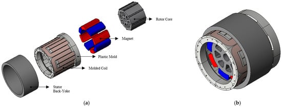
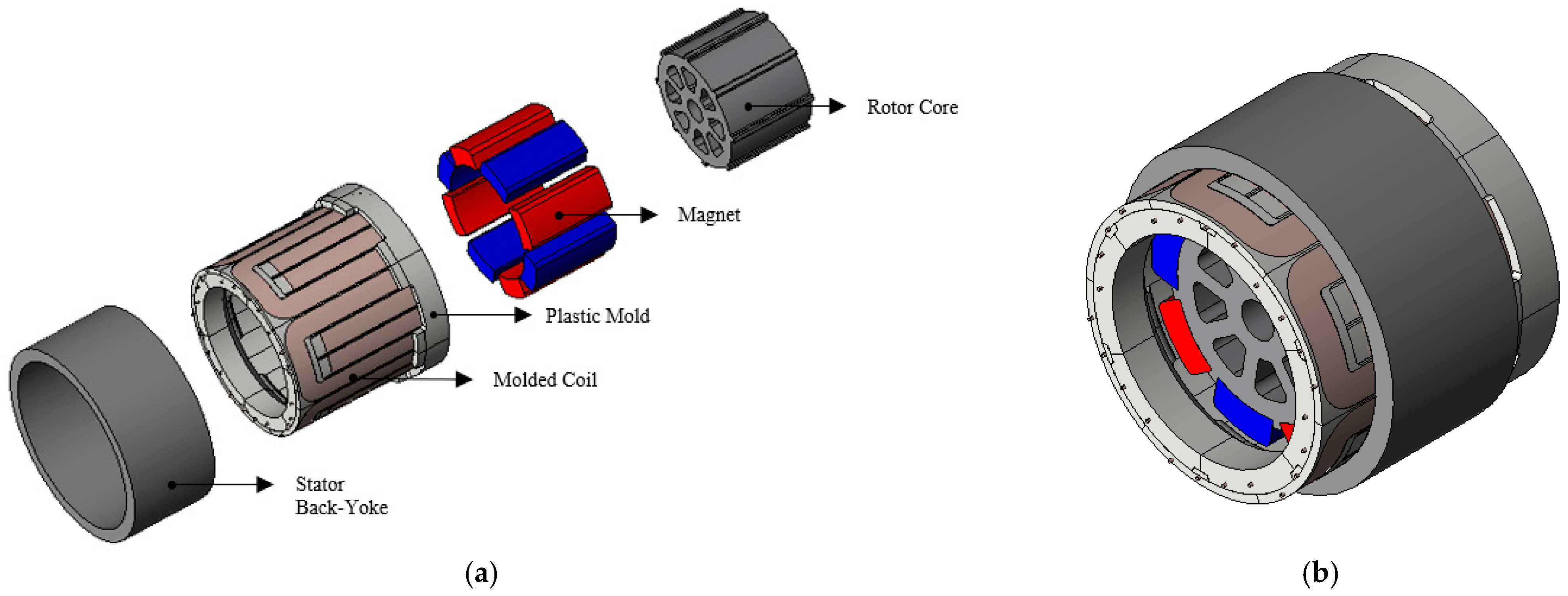
A conventional slotless R-EPS motor was selected as the baseline, as shown in Figure 1, Red and blue represent the north (N) and south (S) poles of the magnets, respectively. to establish the performance and size requirements for the proposed design. As illustrated in the exploded view of Figure 1a and the assembled view of Figure 1b, the motor consists of an inner rotor carrying surface-mounted permanent magnets, an air-gap winding wound directly without stator teeth, and a slotless cylindrical stator back-yoke that provides the magnetic return path; these components are enclosed by the housing and end brackets supported on the shaft and bearings. The labeled exploded view further identifies the rotor core, permanent magnets, plastic mold, molded coil, and stator back-yoke, which constitute the main electromagnetic and mechanical support components of the baseline slotless R-EPS motor. In operation, the permanent magnets establish a radial air-gap field, and three-phase currents in the air-gap winding interact with this field to produce torque. Because the slotless stator presents a smooth bore with no teeth, the air-gap reluctance remains constant during rotor rotation, so cogging torque is theoretically eliminated, and the back-EMF waveform is governed primarily by the magnet shape rather than by tooth-slot geometry. The conventional motor operates at a rated speed of 1000 rpm with a rated torque of 3.41 Nm, delivering an output power of 355 W and a gravimetric power density of 259.17 W/kg with an active part weight of 1.37 kg. Detailed specifications of the conventional motor are summarized in Table 1.
Figure 1.
Conventional slotless R-EPS motor: (a) exploded view, (b) assembled view.
Table 1.
Specifications of the Conventional Motor.
To ensure equivalent or superior output performance while achieving meaningful reductions in cogging torque, torque ripple, and active part weight, the proposed slotless motor was designed based on the specifications of the conventional motor. The design targets include maximizing gravimetric power density and minimizing electromagnetic vibration sources within the given spatial constraints of the R-EPS installation environment. The detailed design methodology and resulting specifications of the proposed motor are presented in the following section.
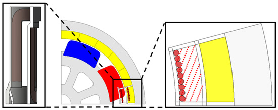
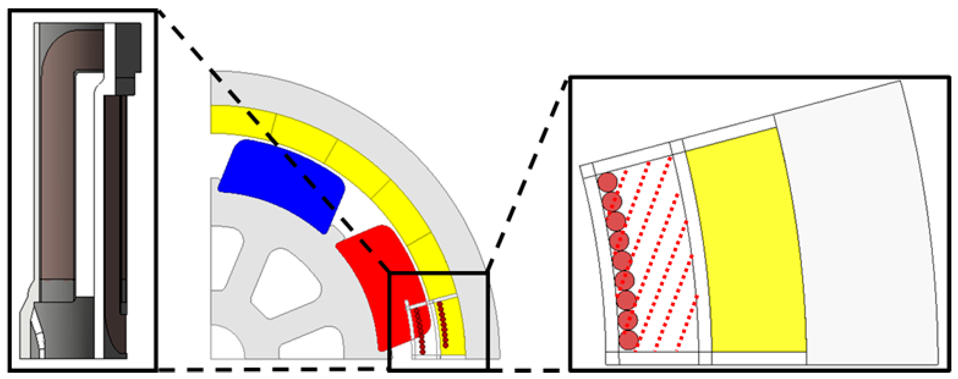
In this study, the stator outer diameter and coil specifications of the conventional slotless R-EPS motor were fixed in accordance with the requirements of the manufacturing partner. Therefore, the design variables available for optimization were limited to the permanent magnet shape parameters. As illustrated in Figure 2, the red hatched region represents the actual coil winding area, while the yellow highlighted region on the right indicates the curved lower section of the winding. A detailed verification of the coil turn validity within the innermost winding region was beyond the scope of this study, as the primary objectives are to improve power density and torque performance through THD minimization under a fixed stator configuration. Within these constraints, the permanent magnet geometry was optimized to maximize no-load back-EMF while minimizing total harmonic distortion (THD) of the phase voltage, which directly influences cogging torque and torque ripple in slotless motors.
Figure 2.
Two-dimensional finite element analysis (FEA) model of the conventional slotless R-EPS motor. Cross-sectional view of the motor illustrating the rotor core, stator core, permanent magnets, coil winding region, and stator back yoke. Gray, red, blue, and yellow represent the rotor core and stator core, north (N) pole, south (S) pole, and coil winding region, respectively.
3. Proposed Motor Design and Optimization
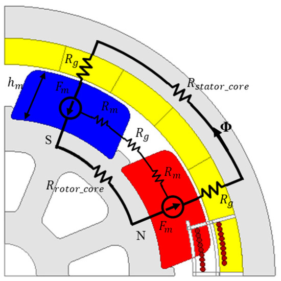
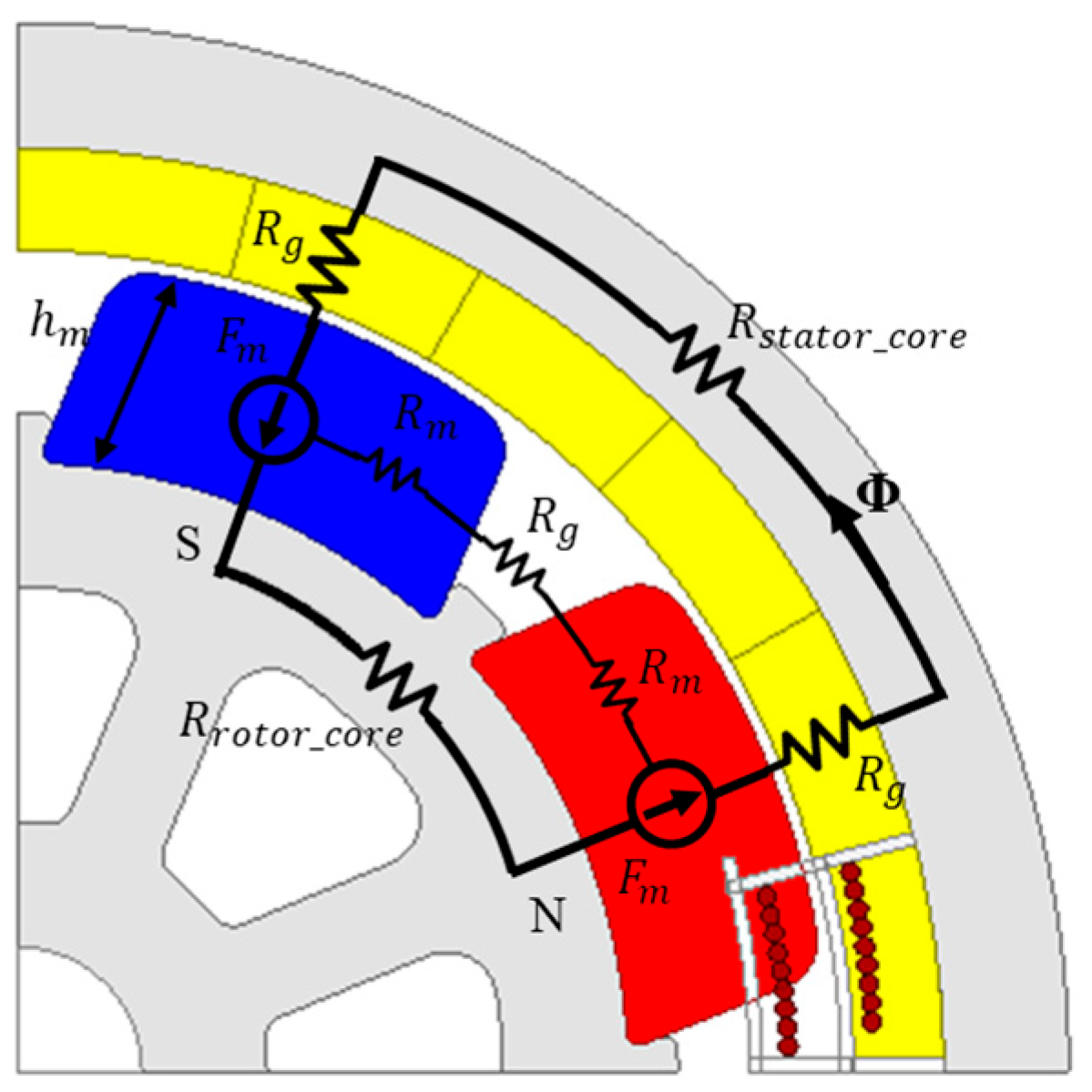
As shown in Figure 3, the Arc-Type permanent magnet is designed such that its inner and outer curvatures conform to the rotor core and stator, maintaining a constant air-gap along the rotational direction θ.
Figure 3.
Magnetic equivalent circuit (MEC) model of the conventional Arc-Type magnet.
In the Arc-Type structure, since the magnet thickness and the air-gap thickness δ is uniform across the entire magnetic pole area, the parameters of the magnetic circuit are treated as constants. The total reluctance of the magnetic circuit is defined as follows
is the internal reluctance of the magnet, and is the air-gap reluctance. The reluctance of the iron core, can be neglected by assuming infinite permeability. Because the Magnetomotive Force (MMF) source is constant and the magnetic reluctance is uniform regardless of position, the air-gap flux density theoretically forms a square wave distribution within the range of the pole arc angle .
This square wave distribution, when decomposed via the Fourier series, contains substantial high-order harmonic components that directly elevate the total harmonic distortion (THD) of the back-EMF, contributing to cogging torque and torque ripple.
3.1. Bar-Type Permanent Magnet Optimization
In contrast to the conventional Arc-Type geometry, the Bar-Type magnet configuration features a non-uniform air-gap δ(θ) that varies with angular position [18]. This enables flux shaping, in which the magnetic equivalent circuit (MEC) parameters are tailored to improve the harmonic profile of the back-EMF [19].
The air-gap reluctance and the resulting air-gap flux density for a Bar-Type structure can be defined as Equations (3) and (4).
By substituting the position-dependent air-gap function into Equation (4), it is evident that the air-gap flux density is no longer constant across the pole arc. Since the air-gap length increases as the angular position moves from the center toward the pole edges, the flux density naturally attenuates at the magnet peripheries. This physical characteristic transforms the conventional square wave distribution into a more sinusoidal profile, effectively suppressing high-order harmonics that contribute to Total Harmonic Distortion (THD).
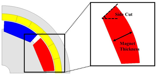
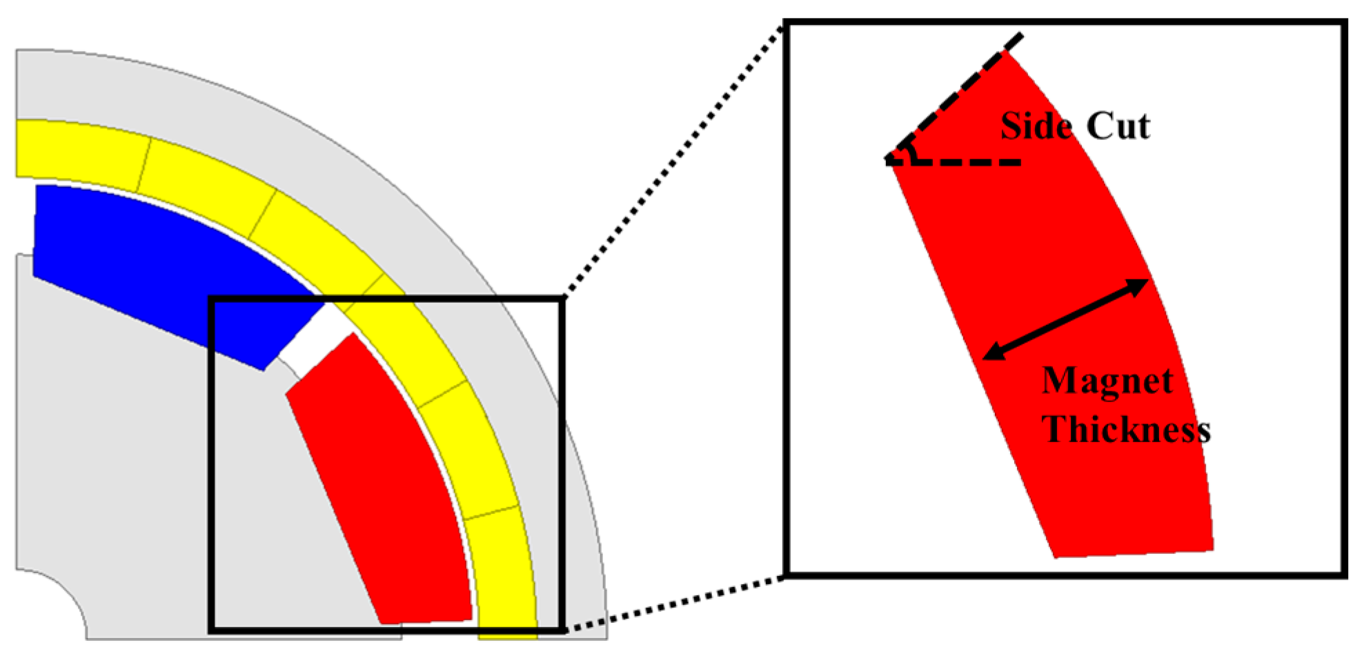
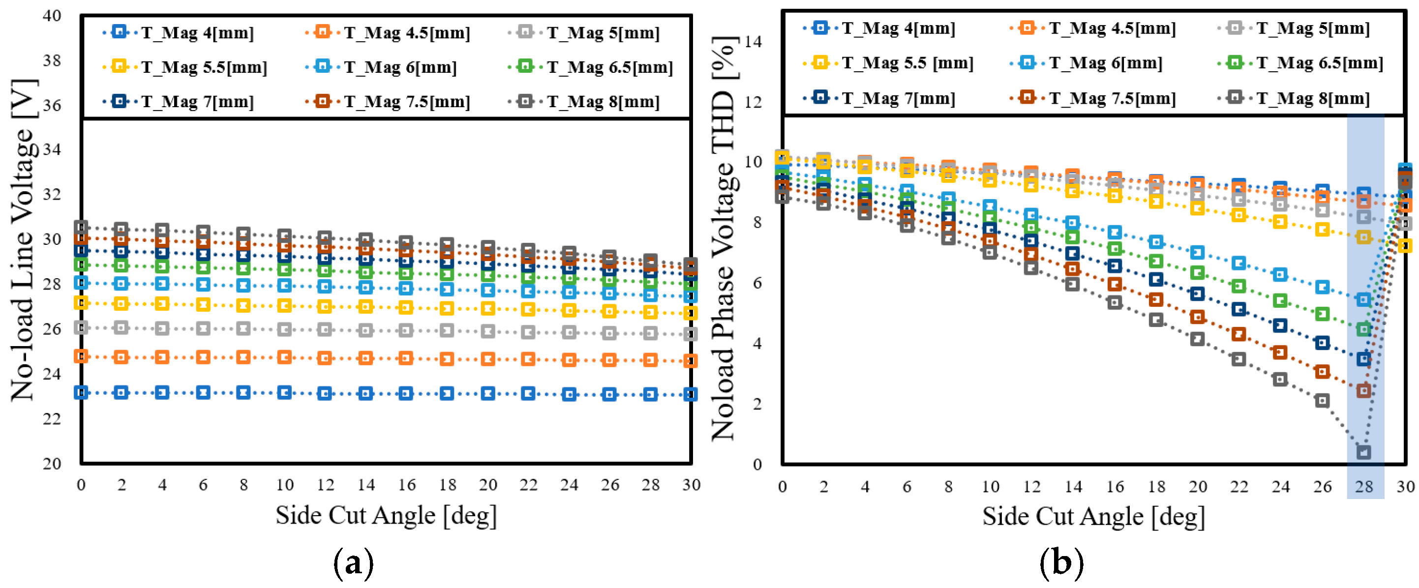
An additional degree of freedom is introduced through a side-cut geometry at the magnet edges, as shown in Figure 4 [20]. By tuning the side-cut angle, the effective pole arc and the flux density transition slope can be precisely controlled, enabling targeted suppression of specific harmonic components in the back-EMF. Parametric simulations confirm that an optimized side-cut angle can reduce the THD to below 1%, which is essential for EPS applications requiring smooth torque delivery and minimal vibration.
Figure 4.
Analysis model of the Bar-Type magnet geometry.
However, an excessive side-cut reduces the fundamental flux density component, which may compromise average torque output. Therefore, the magnet thickness and side-cut angle were selected through an iterative optimization process to satisfy both torque density and NVH requirements simultaneously, as illustrated in Figure 5.
Figure 5.
Parametric analysis of no-load characteristics according to magnet thickness and side-cut angle: (a) No-load line-to-line back-EMF; (b) No-load phase voltage THD.
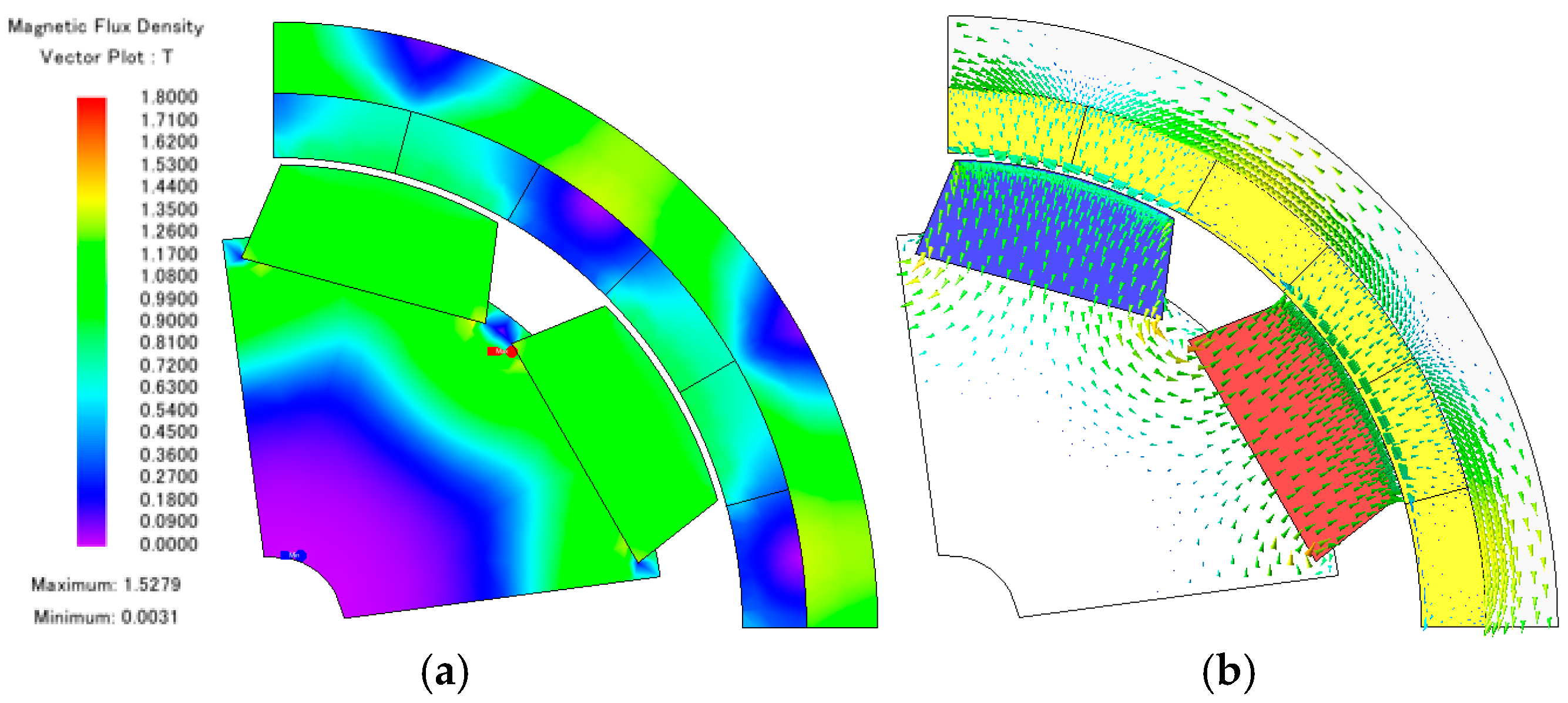
Based on the comprehensive parametric analysis, a magnet thickness of 8.0 mm and a side-cut angle of 28° were selected as the final design parameters for the 48 V EPS motor. This configuration achieves a no-load line-to-line back-EMF of 30.05 Vrms and a minimum phase voltage THD of 0.38%. Furthermore, a performance comparison was conducted through load analysis to verify the operational characteristics of the optimized design, with the load magnetic field distribution of the proposed Bar-Type model shown in Figure 6, and the results are summarized in Table 2. The optimized design meets the required torque and efficiency targets under rated operating conditions.
Figure 6.
Load magnetic field distribution of the proposed Bar-Type model (a) Magnetic flux density contour plot; (b) Magnetic flux density vector plot.
Table 2.
Comparison of Performance of Arc-Type Model and Bar-Type Model.
3.2. Double-Bridge Lightweight Rotor Design
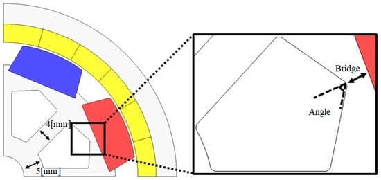
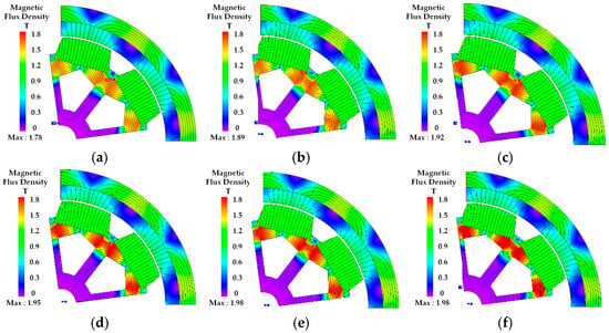
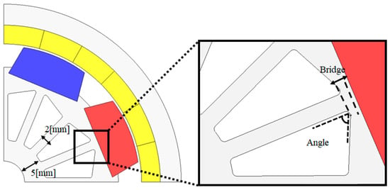
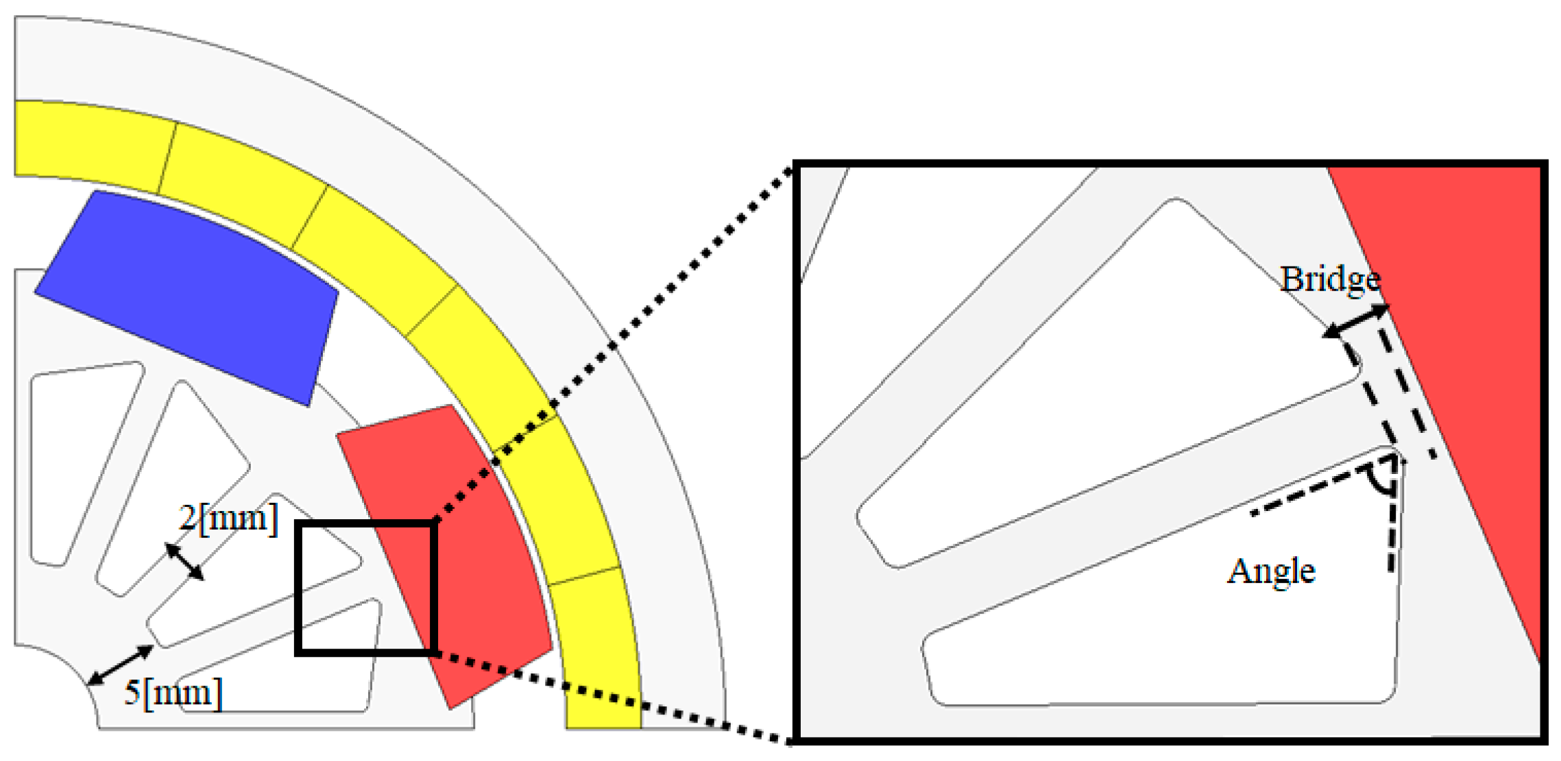
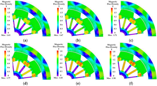
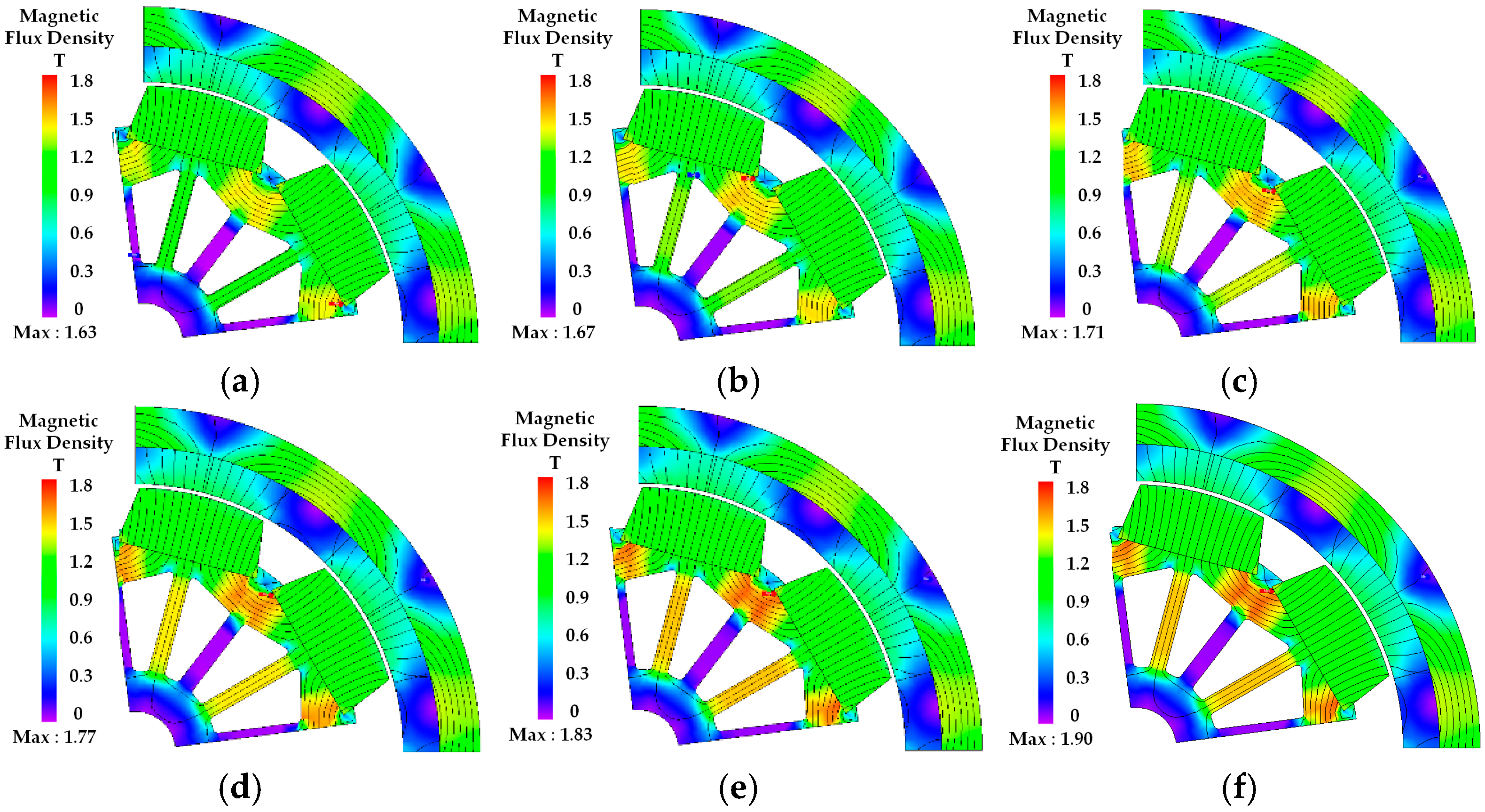
The analysis results in Table 2 confirm improvements in no-load back-EMF, torque and output power. However, because the rotor lightweight design has not yet been implemented, the total weight is 0.24 kg higher, resulting in a power density that is 18.13 W/kg lower than the conventional motor. Consequently, a rotor lightweight design is conducted on the proposed model to address this deficiency. As illustrated in Figure 7, both Polygon-type and Bridge-type topologies are proposed. The optimal rotor geometry is derived by observing the trends in magnetic flux density saturation relative to various bridge thicknesses and angles, with the saturation analysis for the polygon-type rotor presented in Figure 8.
Figure 7.
Polygon-type lightweight rotor topology.
Figure 8.
The magnetic flux density saturation analysis for the proposed polygon-type rotor as a function of bridge thickness and rib angles. (a) 55°; (b) 57°; (c) 59°; (d) 61°; (e) 63°; (f) 65°; (bridge thickness: 2 mm).
The analysis results revealed that for the polygon-type configuration, magnetic saturation exceeding 1.8 Tesla occurred in the rotor back-yoke region due to the thin bridge thickness. Consequently, a dual-bridge rotor lightweight topology, featuring an iron core inserted into the center of the polygon rotor shape, is presented in Figure 9. Similarly, Figure 10 illustrates the magnetic flux density saturation trends at various angles for a bridge thickness of 2 mm.
Figure 9.
Double-bridge lightweight rotor topology.
Figure 10.
The magnetic flux density saturation analysis for the proposed bridge-type rotor as a function of bridge thickness and rib angles. (a) 55°; (b) 57°; (c) 59°; (d) 61°; (e) 63°; (f) 65° (bridge thickness: 2 mm).
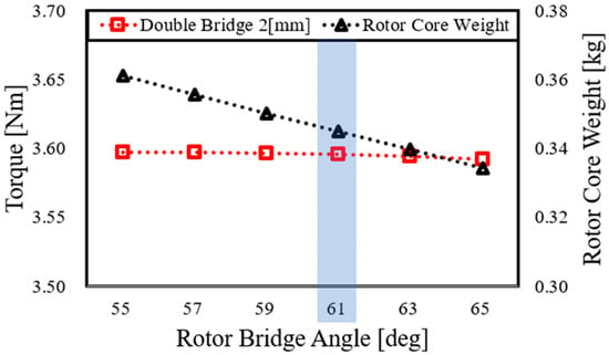
The analysis results indicated that for the double-bridge rotor configuration, some magnetic flux leakage occurred due to the insertion of the central iron core; however, this modification effectively reduced the magnetic saturation level in the back-yoke region. Consequently, the trends in torque and weight based on this analysis model are illustrated in Figure 11, and model (d) in Figure 10 was selected as the final design as it satisfies the saturation limit of under 1.8 Tesla without compromising electromagnetic performance.
Figure 11.
Variation in output torque and rotor core weight as a function of the rotor bridge angle.
3.3. Structural Integrity Analysis
To ensure the mechanical reliability of the proposed Double Bridge lightweight rotor, a structural integrity analysis was performed using Finite Element Analysis (FEA) [21]. While the primary goal of the “Polygon” and “Double Bridge” topologies was to enhance power density through weight reduction, it is critical to verify that the reduced bridge thickness can withstand the centrifugal forces generated at maximum operating speeds. The analysis was conducted under the maximum rated speed of the EPS motor. The material properties of the rotor core (electrical steel) were defined with a Yield Strength of 275 MPa. The main objective was to ensure that both the induced stress and radial deformation remain within safe limits to prevent structural failure or air-gap interference.
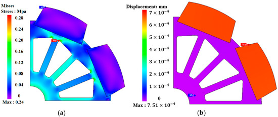
The distribution of von Mises stress and the resulting radial displacement across the rotor cross-section are illustrated in Figure 12. The mechanical stress distribution is shown in Figure 12a. The maximum von Mises stress occurs at the inner edges of the bridge, reaching a value of 0.24 MPa. This stress level is concentrated at the sharp corners of the bridge and rib areas, which act as the primary mechanical supports for the permanent magnets against centrifugal load. The radial displacement distribution is illustrated in Figure 12b. The maximum displacement is recorded as mm, occurring at the outermost sections of the permanent magnets. This negligible deformation indicates that the structural rigidity of the optimized rotor is sufficient to maintain a consistent air-gap clearance, ensuring magnetic stability and preventing any physical contact between the rotor and stator during operation.
Figure 12.
Structural analysis results (a) von Mises stress; (b) radial displacement.
To quantitatively evaluate the structural reliability, the Safety Factor (SF) was calculated using the following Equation (5).
Given the yield strength of 275 MPa and a maximum induced stress of 0.24 MPa, the calculated safety factor is approximately 1146. In general mechanical design, a safety factor between 1.5 and 2.0 is considered sufficient for reliable operation. The calculated safety factor of 1146 far exceeds this threshold, confirming that the proposed double-bridge rotor maintains structural robustness despite the significant weight reduction.
3.4. Electromagnetic Performance Comparison
With the structural integrity of the double-bridge rotor confirmed, this section presents a comparative analysis of the electromagnetic performance between the conventional Arc-Type and the optimized Bar-Type rotor models. The key performance metrics, including back-EMF, torque output, core loss, and efficiency, are evaluated based on finite element analysis (FEA) results and summarized in Table 3.
Table 3.
Performance comparison between the conventional Arc-Type and the Bar-Type rotor models.
The FEA results show that the proposed Bar-Type model outperforms the conventional Arc-Type motor in several key areas. The no-load line-to-line back-EMF increased from 25.11 Vrms to 26.4 Vrms, which directly contributed to a 4.97% increase in output torque (from 3.42 Nm to 3.59 Nm). Furthermore, the core loss was significantly reduced from 2.45 W to 1.72 W, representing a 29.8% reduction [22,23]. This improvement in the electromagnetic loss profile, combined with the higher torque output, resulted in an overall efficiency enhancement from 66.66% to 67.87%. To address torque ripple reduction, Section 3.5 performs a comparative FFT analysis of the torque produced by existing Arc-Type and Bar-Type motor designs.
3.5. Torque Harmonic Analysis and Magnet Edge Filet Optimization
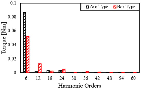
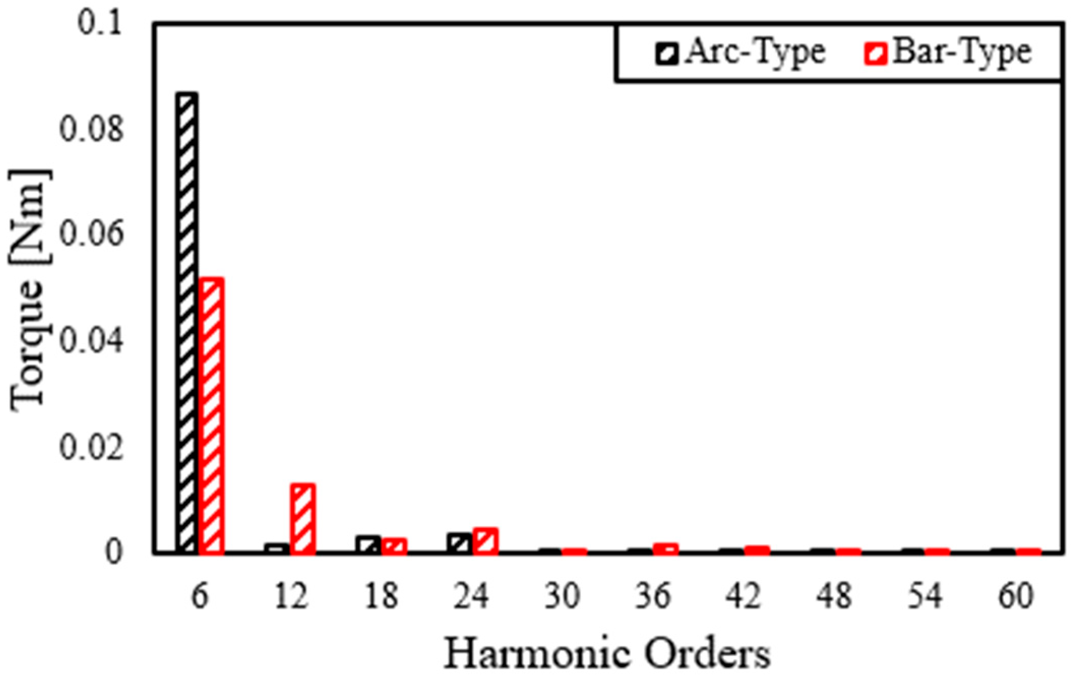
This section examines the torque ripple characteristics of the conventional Arc-Type rotor and the optimized Bar-Type rotor. To investigate the specific frequency components contributing to torque fluctuation, a Fast Fourier Transform (FFT) analysis was performed, with the results illustrated in Figure 13. Although the time-domain waveforms are similar owing to the slotless structure, the harmonic spectra provide a more sensitive and quantitative indication of the effect of magnet shaping.
Figure 13.
Fast Fourier Transform (FFT) analysis results.
As shown in Figure 13, the Bar-Type rotor significantly reduces the dominant 6th-order harmonic compared with the Arc-Type rotor, whereas some higher-order components, such as the 12th, 24th, 36th, and 42nd harmonics, are relatively increased. This harmonic redistribution arises because part of the energy suppressed at the dominant 6th-order component is transferred to higher-order multiples due to the geometric saliency and sharp flux-transition points of the Bar-Type topology [24,25,26]. Although these high-order harmonics are small in absolute magnitude, they may still affect steering NVH performance by inducing high-frequency vibration components [27].
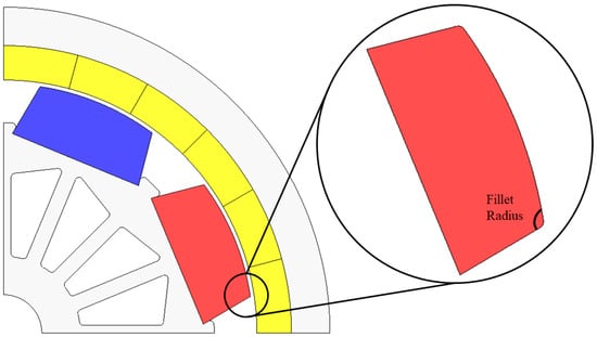
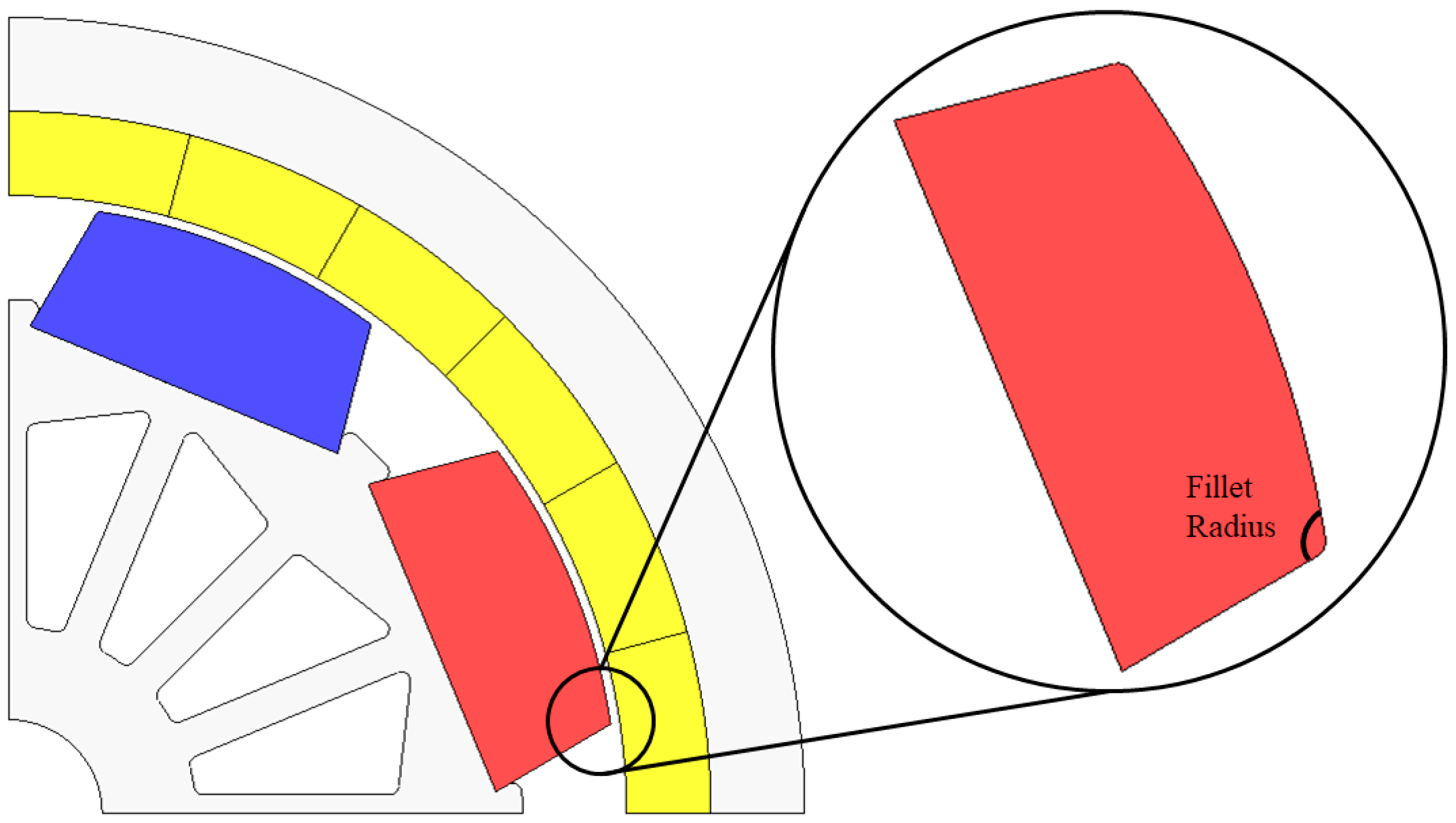
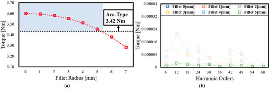
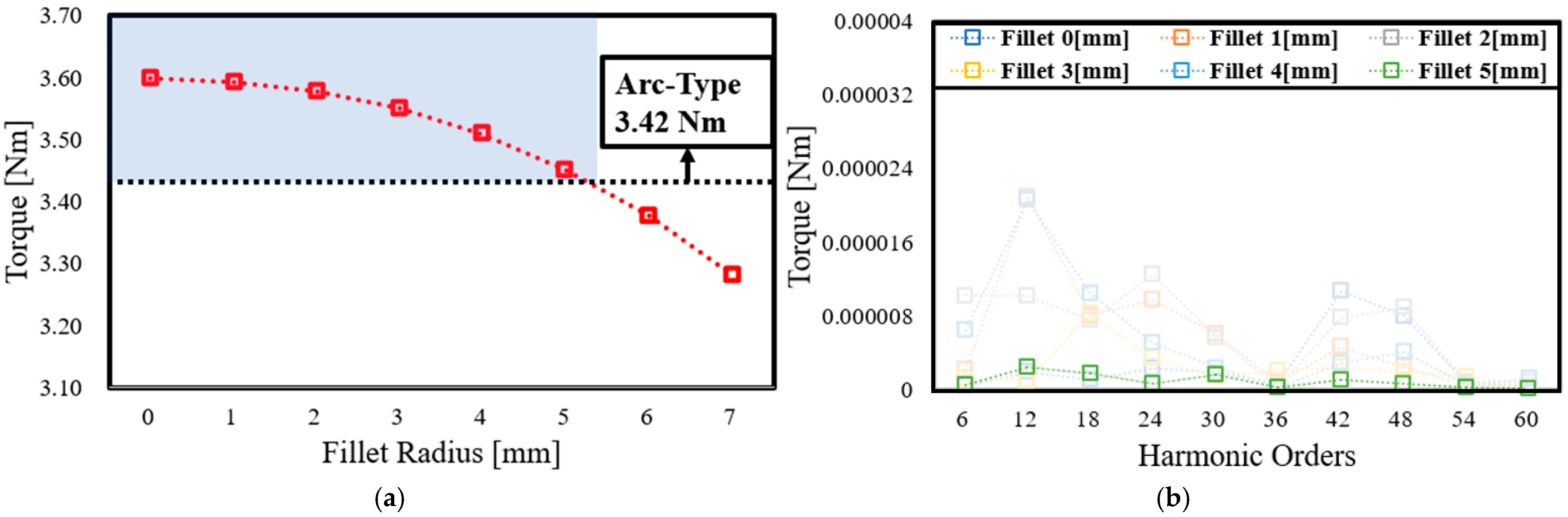
To mitigate these harmonic risks while maintaining the high average torque characteristic of the Bar-Type design, a filet geometry was implemented at the magnet extremities. Figure 14. presents the proposed magnet edge fileting intended to smooth the air-gap flux density distribution, and Figure 15. analyzes the resulting reduction in dominant torque harmonics as a function of the filet radius.
Figure 14.
Proposed magnet edge fileting for torque ripple and THD reduction.
Figure 15.
(a) Characteristics of average torque as a function of the magnet filet radius; (b) harmonic orders as a function of the magnet filet radius.
The analysis in Figure 15a demonstrates that while the average torque of the Bar-Type rotor decreases as the filet radius increases, it remains above the Arc-Type baseline of 3.42 Nm up to a 5 mm filet radius. Furthermore, as shown in Figure 15b, increasing the filet radius effectively attenuates the torque harmonics across major orders. In particular, the 5 mm filet was identified as the optimal design point, offering the most significant suppression of high-order harmonic components while maintaining the required output torque.
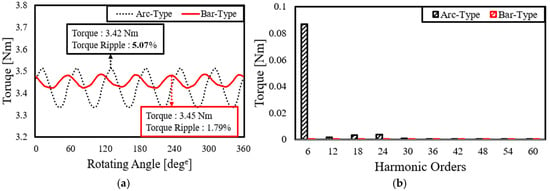
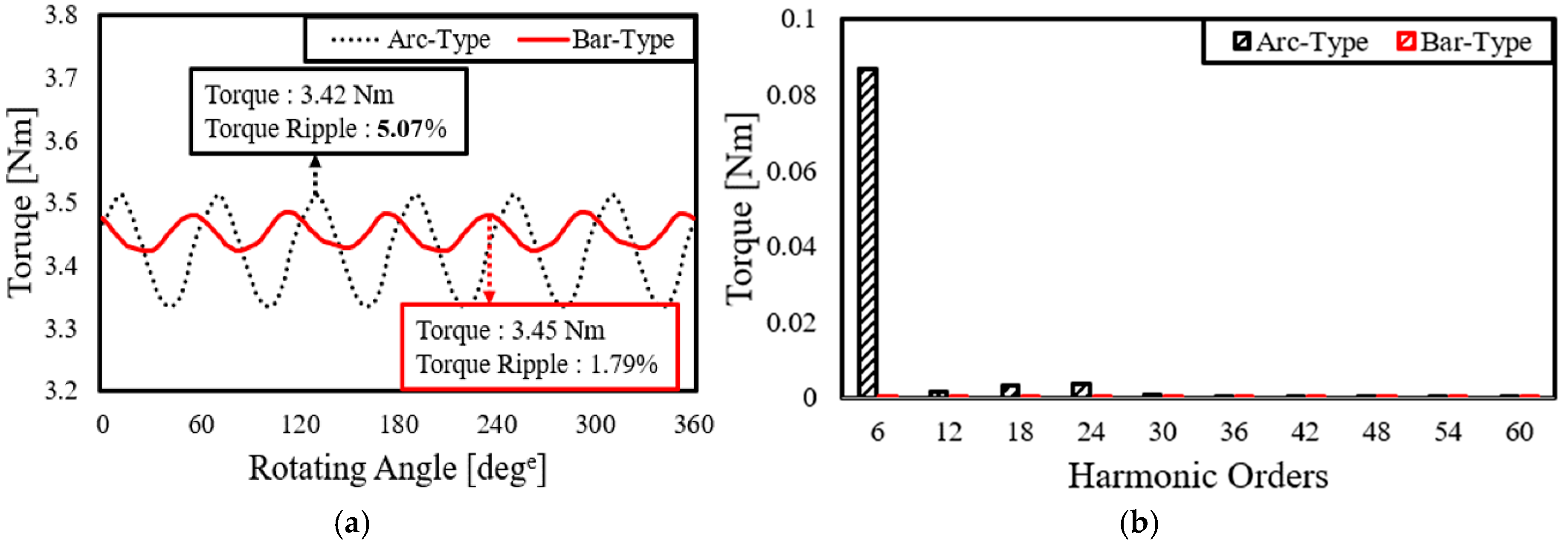
Based on these findings, the 5 mm filet design was selected to maximize the reduction in noise and vibration without compromising electromagnetic performance. Consequently, a comparative FFT analysis of the conventional Arc-Type and the optimized Bar-Type with a 5 mm filet is presented in Figure 16 for final performance validation. The FFT analysis reveals that for both models, the torque ripple is dominated by the 6th harmonic and its multiples, which is characteristic of the slot-pole combination of the designed motor.
Figure 16.
Torque and harmonic analysis: (a) comparison of torque waveforms; (b) comparison of harmonic orders.
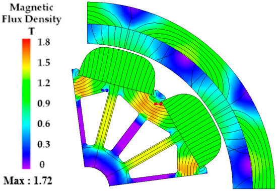
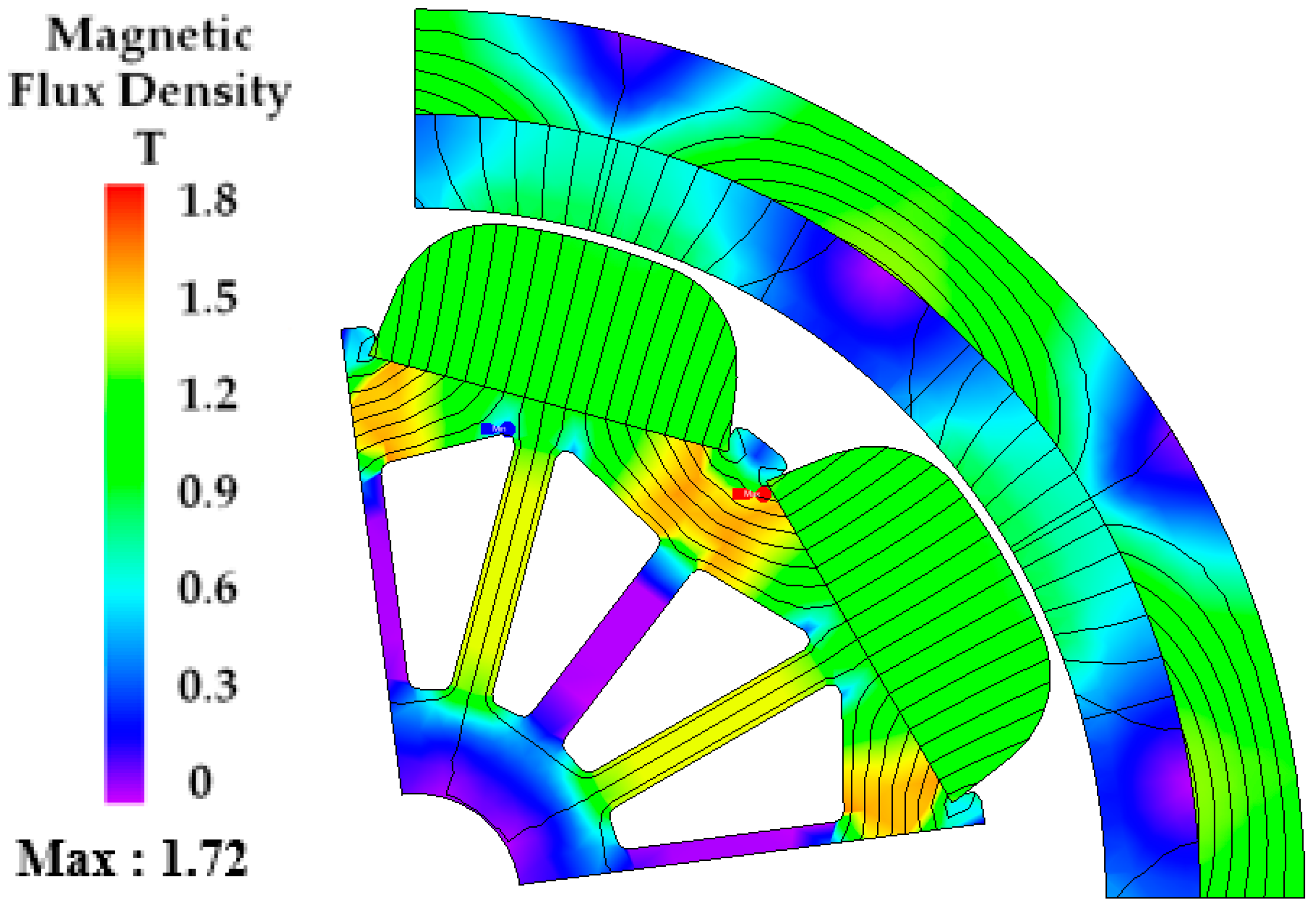
According to the torque analysis illustrated in Figure 16a, the implementation of the filet resulted in a decrease in the average torque of the Bar-Type rotor from 3.59 Nm to 3.45 Nm. Conversely, the torque ripple was reduced by approximately 50%, falling from 3.87% to 1.79%, primarily due to the effective suppression of dominant harmonic orders. Consequently, this configuration was selected as the final model. Table 4 and Figure 17 present the final results: Table 4 provides a comprehensive performance comparison of the electromagnetic performance between the conventional Arc-Type motor and the final optimized Bar-Type model with the 5 mm filet, while Figure 17. shows the magnetic flux density distribution of the final optimized Bar-Type model.
Table 4.
Performance comparison between the conventional Arc-Type and the optimized Bar-Type rotor models.
Figure 17.
Magnetic flux density distribution of the final optimized Bar-Type model.
4. Conclusions
This paper presented a slotless SPMSM with a Bar-Type permanent magnet and a double-bridge rotor lightweight topology for 48 V rack-type EPS applications. The following conclusions are drawn: (1) Bar-Type magnet shape optimization: By introducing a non-uniform air-gap profile with a 28° side-cut angle, the Bar-Type magnet geometry achieves a no-load back-EMF THD of 0.38%, directly reducing cogging torque and torque ripple relative to the conventional Arc-Type design. (2) Magnet edge filet optimization: A 5 mm filet radius at the magnet extremities suppresses dominant torque harmonic orders while preserving an average torque of 3.45 Nm, which exceeds the conventional motor baseline of 3.42 Nm. Torque ripple was reduced from 3.87% to 1.79%, a 53.7% improvement. (3) Double-bridge rotor lightweight topology: The proposed rotor reduces the active part weight to 1.30 kg while maintaining rotor back-yoke flux density below the 1.8 T saturation limit. The structural safety factor was confirmed to be 1146 under maximum-speed centrifugal loading, far exceeding the general design requirement of 1.5–2.0. (4) FEA-based performance verification: The optimized design achieved an output power of 359.9 W at 1000 rpm with a torque of 3.45 Nm, yielding a gravimetric power density of 276.85 W/kg. This work demonstrates a systematic design methodology for slotless R-EPS motors in 48 V systems and provides a viable engineering solution for next-generation automotive steering applications demanding both high power density and ultra-low NVH characteristics. Given the relatively high current density and the efficiency of approximately 67% reported in this study, future work will focus on thermal management and temperature-rise validation to assess motor reliability under continuous operating conditions [28], together with prototype fabrication, experimental validation, and closed-loop control validation under dynamic steering load profiles [29,30].
Author Contributions
Conceptualization, D.-Y.S. and W.-H.K.; methodology, D.-Y.S.; software, D.-Y.S.; validation, D.-Y.S., D.-H.C. and H.-S.H.; formal analysis, D.-Y.S. and D.-H.C.; investigation, D.-Y.S. and H.-S.H.; resources, D.D. and W.-H.K.; data curation, D.-Y.S.; writing—original draft preparation, D.-Y.S.; writing—review and editing, D.D. and W.-H.K.; visualization, D.-Y.S.; supervision, W.-H.K.; project administration, W.-H.K.; funding acquisition, W.-H.K. All authors have read and agreed to the published version of the manuscript.
Funding
This research was funded by the Korea Institute for Advancement of Technology (KIAT) grant funded by the Ministry of Trade, Industry and Energy (MOTIE) (Project No. RS-2024-00436216, Human Resource Development Program for Industrial Innovation (Global)); and the Korea Institute of Energy Technology Evaluation and Planning (KETEP) and the Ministry of Trade, Industry and Energy (MOTIE) of the Republic of Korea, grant number RS-2023-00232767.
Data Availability Statement
The original contributions presented in the study are included in the article; further inquiries can be directed to the corresponding author.
Conflicts of Interest
The authors declare no conflicts of interest.
References
- Wrobel, J.; Pietrusiak, D.; Fiebig, W.; Czechowski, M. Automotive Electric Power Steering Systems NVH Performance Investigations. Int. J. Automot. Technol. 2022, 23, 1153–1161. [Google Scholar] [CrossRef] [Scilit]
- Zhu, Z.Q.; Howe, D. Electrical Machines and Drives for Electric, Hybrid, and Fuel Cell Vehicles. Proc. IEEE 2007, 95, 746–765. [Google Scholar] [CrossRef] [Scilit]
- Lee, C.-S.; Hwang, K.-Y.; Kim, W.-H. Design and Validation of SPMSM with Step-Skew Rotor for EPS System Using Cycloid Curve. Machines 2025, 13, 814. [Google Scholar] [CrossRef] [Scilit]
- Pellegrino, G.; Vagati, A.; Guglielmi, P.; Boazzo, B. Performance Comparison Between Surface-Mounted and Interior PM Motor Drives for Electric Vehicle Application. IEEE Trans. Ind. Electron. 2012, 59, 803–811. [Google Scholar] [CrossRef] [Scilit]
- Gieras, J.F.; Wing, M. Permanent Magnet Motor Technology: Design and Applications, 3rd ed.; CRC Press: Boca Raton, FL, USA, 2010. [Google Scholar]
- Hanselman, D.C. Brushless Permanent Magnet Motor Design, 2nd ed.; Magna Physics Publishing: Lebanon, OH, USA, 2006. [Google Scholar]
- Yongping, L.; Yong, L. Tooth-Slot Cogging Torque and Noise Analysis of Permanent Magnet Motors. In Proceedings of the Fifth International Conference on Electrical Machines and Systems (ICEMS 2001), Shenyang, China, 18–20 August 2001; pp. 860–862. [Google Scholar] [CrossRef] [Scilit]
- Islam, R.; Husain, I.; Fardoun, A.; McLaughlin, K. Permanent-Magnet Synchronous Motor Magnet Designs with Skewing for Torque Ripple and Cogging Torque Reduction. IEEE Trans. Ind. Appl. 2009, 45, 152–160. [Google Scholar] [CrossRef] [Scilit]
- Bianchi, N.; Bolognani, S. Design Techniques for Reducing the Cogging Torque in Surface-Mounted PM Motors. IEEE Trans. Ind. Appl. 2002, 38, 1259–1265. [Google Scholar] [CrossRef] [Scilit]
- Zhu, Z.Q.; Ruangsinchaiwanich, S.; Howe, D. Synthesis of Cogging-Torque Waveform from Slot-Harmonic Spectra. IEEE Trans. Ind. Appl. 2006, 42, 650–657. [Google Scholar] [CrossRef] [Scilit]
- Hwang, S.M.; Eom, J.B.; Jung, Y.H.; Lee, D.W.; Kang, B.S. Various Design Techniques to Reduce Cogging Torque by Controlling Energy Variation in Permanent Magnet Motors. IEEE Trans. Magn. 2001, 37, 2806–2809. [Google Scholar] [CrossRef] [Scilit]
- Hao, W.; Zhang, G.; Liu, W.; Liu, H.; Wang, Y. Methods for Reducing Cogging Force in Permanent Magnet Machines: A Review. Energies 2023, 16, 422. [Google Scholar] [CrossRef] [Scilit]
- Wang, D.; Wang, X.; Jung, S.-Y. Cogging Torque Minimization and Torque Ripple Suppression in Surface-Mounted Permanent Magnet Synchronous Machines Using Different Magnet Widths. IEEE Trans. Magn. 2013, 49, 2290–2296. [Google Scholar] [CrossRef] [Scilit]
- Choi, D.-H.; Kim, D.-H.; Han, H.-S.; Jung, D.-H.; Kim, W.-H. Design of a Slotless Structure for Minimizing Cogging Torque and Torque Ripple in a Column Type EPS Motor for Vehicles. IEEE Trans. Magn. 2024, 60, 8700305. [Google Scholar] [CrossRef] [Scilit]
- Praveen, R.P.; Ravichandran, M.H.; Sadasivan Achari, V.T.; Jagathy Raj, V.P.; Madhu, G.; Bindu, G.R. A Novel Slotless Halbach-Array Permanent-Magnet Brushless DC Motor for Spacecraft Applications. IEEE Trans. Ind. Electron. 2012, 59, 3553–3560. [Google Scholar] [CrossRef] [Scilit]
- Park, J.-W.; Hwang, K.-Y.; Kim, W.-H. Performance Comparison Analysis and Process Suggestion Through Slotless SPMSM During High-Speed Operation. AIP Adv. 2023, 13, 025039. [Google Scholar] [CrossRef] [Scilit]
- Xu, L.; Zhao, W.; Liu, G.; Song, C. Design Optimization of a Spoke-Type Permanent Magnet Vernier Machine for Torque Density and Power Factor Improvement. IEEE Trans. Veh. Technol. 2019, 68, 3446–3456. [Google Scholar] [CrossRef] [Scilit]
- Zhao, W.; Lipo, T.A.; Kwon, B.-I. Material-Efficient Permanent-Magnet Shape for Torque Pulsation Minimization in SPM Motors for Automotive Applications. IEEE Trans. Ind. Electron. 2014, 61, 5779–5787. [Google Scholar] [CrossRef] [Scilit]
- Hsieh, M.-F.; Hsu, Y.-C. A Generalized Magnetic Circuit Modeling Approach for Design of Surface Permanent-Magnet Machines. IEEE Trans. Ind. Electron. 2012, 59, 779–792. [Google Scholar] [CrossRef] [Scilit]
- Choi, D.-H.; Jo, C.; Han, H.-S.; Kim, H.-G.; Kim, W.-H.; Kim, H. Design of a Six-Phase Surface Permanent-Magnet Synchronous Motor with Chamfer-Shaped Magnet to Reduce Cogging Torque and Torque Ripple for Large-Ship Propulsion. Appl. Sci. 2025, 15, 11400. [Google Scholar] [CrossRef] [Scilit]
- Monissen, C.; Arslan, M.E.; Krings, A.; Andert, J. Mechanical Stress in Rotors of Permanent Magnet Machines—Comparison of Different Determination Methods. Energies 2022, 15, 9169. [Google Scholar] [CrossRef] [Scilit]
- Roshen, W. Iron Loss Model for Permanent-Magnet Synchronous Motors. IEEE Trans. Magn. 2007, 43, 3428–3434. [Google Scholar] [CrossRef] [Scilit]
- Sirimanna, S.; Balachandran, T.; Haran, K. A Review on Magnet Loss Analysis, Validation, Design Considerations, and Reduction Strategies in Permanent Magnet Synchronous Motors. Energies 2022, 15, 6116. [Google Scholar] [CrossRef] [Scilit]
- Jo, C.; Kim, S.; Lee, J. Design of Rotor Pole Arrangement for Torque Ripple Reduction in Consequent Pole Permanent Magnet Synchronous Motors. Machines 2026, 14, 662. [Google Scholar] [CrossRef] [Scilit]
- Zhu, Z.Q.; Liu, Y. Analysis of Air-Gap Field Modulation and Magnetic Gearing Effect in Fractional-Slot Concentrated-Winding Permanent-Magnet Synchronous Machines. IEEE Trans. Ind. Electron. 2018, 65, 3688–3698. [Google Scholar] [CrossRef] [Scilit]
- Głąb, I.; Wszołek, T.; Drabek, T.; Czechowski, M.; Wróbel, J.; Pietrusiak, D. Identification of Magnetic-Borne Noise in Automotive Electric Power Steering Systems. Energies 2025, 18, 6181. [Google Scholar] [CrossRef] [Scilit]
- Horváth, K.; Zelei, A. Simulating Noise, Vibration, and Harshness Advances in Electric Vehicle Powertrains: Strategies and Challenges. World Electr. Veh. J. 2024, 15, 367. [Google Scholar] [CrossRef] [Scilit]
- Zhang, Y.; McLoone, S.; Cao, W.; Qiu, F.; Gerada, C. Power Loss and Thermal Analysis of a MW High Speed Permanent Magnet Synchronous Machine. IEEE Trans. Energy Convers. 2017, 32, 1468–1478. [Google Scholar] [CrossRef] [Scilit]
- Kim, S.; Choi, M.; Sung, J. Experimental Verifications of Electric Power Steering Controller Based on Discrete-Time Sliding Mode Control with Disturbance Observer. Int. J. Automot. Technol. 2023, 24, 883–888. [Google Scholar] [CrossRef] [Scilit]
- Na, S.; Li, Z.; Qiu, F.; Zhang, C. Torque Control of Electric Power Steering Systems Based on Improved Active Disturbance Rejection Control. Math. Probl. Eng. 2020, 2020, 6509607. [Google Scholar] [CrossRef] [Scilit]

Disclaimer/Publisher’s Note: The statements, opinions and data contained in all publications are solely those of the individual author(s) and contributor(s) and not of MDPI and/or the editor(s). MDPI and/or the editor(s) disclaim responsibility for any injury to people or property resulting from any ideas, methods, instructions or products referred to in the content. |
© 2026 by the authors. Licensee MDPI, Basel, Switzerland. This article is an open access article distributed under the terms and conditions of the Creative Commons Attribution (CC BY) license.