


Abstract
This paper presents a control system for a powder sintering machine utilizing the alternating current (AC) sintering technique assisted by uniaxial compression. The AC flows simultaneously through both the sintered material and the die assembly. The procedural model of the control system and its functionalities are described. Thermal models of the die assembly were developed using First-Order Plus Dead-Time (FOPDT) and Second-Order Plus Dead-Time (SOPDT) frameworks, followed by the synthesis of the control system. A prototype machine, developed at the University of Radom in cooperation with the University of Life Sciences in Lublin, is discussed, including its control algorithm and key process parameters affecting sample properties, established based on literature data. To achieve temperatures of 1700 °C and above, a specialized high-power supply (180 A, 400 VAC) with phase-angle and integral-cycle (group) control was implemented. The control system is based on a PLC equipped with temperature control loops, alongside measurements of shrinkage (displacement), compaction force, and auxiliary signals (vacuum and cooling systems). A dedicated control algorithm was developed to ensure process repeatability and optimization. For the ZrO2-based composite analyzed in this manuscript, an FOPDT process model was determined, yielding an equivalent transport delay of approximately 83 s and an equivalent time constant of nearly 333 s. Based on this model, PID controller parameters were derived, and a time-profile program control algorithm was developed. Furthermore, based on literature data, selected mechanical properties of composites obtained via AC sintering are presented, which served as foundational design criteria for the developed machine.
1. Introduction
Powder sintering by electroconsolidation is a modern technique that utilizes electric field activation generated by current flow during the thermal–mechanical sintering process [1,2]. In its simplest form, this method involves resistive heating at low voltage (5–40 V) and high current intensity (up to 25 kA), combined with simultaneous uniaxial compression. Alternating current (AC) sintering assisted by uniaxial compression is a variant of Field-Assisted Sintering Techniques (FAST) and serves as an effective alternative to conventional direct current (DC) methods, such as Spark Plasma Sintering (SPS) [3,4].
In this approach, an AC of defined frequency and amplitude is passed through the nanopowder enclosed in a conductive graphite die [5].
Ceramic composites represent a specific group of materials with excellent properties that are increasingly utilized across various industrial sectors. They find extensive applications in the aerospace, military, automotive, and electronic industries [6]. Their primary characteristics include high hardness, exceptional thermal stability, and outstanding resistance to wear and chemical corrosion under extreme operating conditions. A fundamental advantage of these materials is their ability to maintain structural integrity at ultra-high temperatures, whereas high raw material costs and complex post-sintering processing remain their main drawbacks. Consequently, they are widely employed in critical components such as cutting tools, high-temperature structural elements, thermal protection systems, and electronic substrates.
While the primary heating mechanism in both AC and DC sintering is the Joule effect, the application of AC introduces distinctive advantages [7,8,9]. Sintering with alternating current minimizes undesirable electrochemical effects at grain boundaries or electrodes and suppresses ion migration (electromigration), which are common issues in DC sintering of ion-conducting materials or metals. Consequently, the cyclic reversal of current direction in AC sintering promotes a more homogeneous chemical composition and microstructure. Furthermore, the oscillating electric field enhances atomic mobility, increasing the vibration frequency of atoms and inducing localized potential gradients. These phenomena stimulate both surface and bulk diffusion, which are critical for neck formation and rapid densification [2,10,11,12].
AC sintering also offers superior control over the final material properties. It is well established that the physical properties of sintered materials strongly depend on the preparation of powders prior to the sintering process [13]. By adjusting the frequency and amplitude of the current, researchers can precisely influence the sintering kinetics and microstructure, often resulting in smaller grain sizes and improved electrical properties, such as higher ionic conductivity, compared to DC-sintered counterparts [14,15,16,17]. Despite these advantages, AC technology remains under intensive research, and its transition to industrial-scale applications requires further development of robust equipment and control strategies [18,19,20].
The primary objective of this research is to develop high-performance materials while optimizing production costs and ensuring environmental and operator safety based on previously developed risk assessment methodologies [21,22,23,24]. A key focus is to understand the complex physicochemical phenomena occurring during sintering [10,25,26]. To achieve this, it is essential to design specialized machinery equipped with advanced control systems. The proposed control system is designed to optimize key parameters such as current intensity, uniaxial pressure, and temperature, accommodating various nanopowders with different time-dependent heating profiles [27,28,29]. A fundamental aspect of this development is process modeling, which provides insight into the system’s dynamic properties [30]. This is particularly important when sintering ceramic powders with additives, as these constituents significantly alter the process dynamics and, consequently, the requirements for the control algorithms.
This manuscript presents a newly designed electroconsolidation machine and discusses the key aspects of its control system. The study focuses on the development of process models necessary to determine the dynamic characteristics required for optimizing control parameters, ensuring that the desired technological properties of the sintered materials are consistently achieved [31,32,33].
Numerous studies demonstrate that standard PID regulation fails to deliver desired outcomes, frequently resulting in temperature overshoots and thermal oscillations. Crucially, these publications omit any presentation or analysis of the underlying control signal u(t), despite its profound impact on the final properties of the sintered materials. Materials scientists are often unaware of the critical importance of the control signal trajectory, or they exclude these data entirely from their process descriptions. While a conventional PID setup might yield acceptable results in stable industrial operations, such a simplistic approach can prove disastrous for rigorous scientific research—particularly when managed by a less experienced operator.
Analysis of Literature Data on the Influence of Technological Parameters on the Mechanical Properties of Sintered Ceramics.
The technological parameters of the sintering machine are strictly dependent on the physical dimensions and properties of the materials being processed. Consequently, comprehensive knowledge of these relationships is essential during the design and construction of the device. An analysis of literature data regarding mechanical properties enables the appropriate selection of components and the development of new subsystems necessary for conducting research using the prototype machine. The mechanical and tribological properties strictly dictate the applicability of sintered materials. Key microstructural features, including the grain size and porosity of the consolidated material, exert a direct influence on these performance characteristics [34,35,36]. The preparation of powders plays a crucial role in ensuring process reproducibility and the quality of the sintered materials [35,37,38]. During the design and construction of the research station, literature data were used as primary guidelines. To evaluate the quality of the obtained sinters, indicators were selected that can be determined relatively easily, quickly, and cost-effectively: microhardness, fracture toughness, and bending strength. This section presents the influence of the most significant machine parameters that directly affect the properties of the fabricated samples. One of the fundamental parameters for assessing the physical properties of the obtained materials is microhardness. Hardness and crack resistance are critical indicators of the material’s structural integrity [13,29,39,40]. Microhardness (HV) can be calculated using the following equation:
where F is the load, N, and d is the average value of measured diagonals of the indentation, mm [41].
To calculate fracture toughness (KIC), the following relationship can be utilized [42]:
where E—elastic modulus, GPa; Fc—constant of the value Fc ≈ 3; l—crack length measured from the indentation corner, μm; a—half of the length of indentation diagonal, average distance from the center to the corner, μm.
The values of bending strength are determined using the three-point bending method [39]:
where F—the force at the moment of sample division, N; L—length of the sample, mm; b—width of the sample, mm; h—height of the sample in the direction parallel to the applied force, mm.
The indicators presented above are not the only ones determining the properties and structure of the produced samples. The primary advantage of these indicators is the relative simplicity of their determination. However, the preparation of samples for testing remains a challenge; because the material is exceptionally hard, its processing (grinding and polishing) is both costly and time-consuming. Other techniques for determining material quality, such as scanning electron microscopy (SEM) or X-ray diffraction (XRD), are also employed to provide a deeper understanding of the microstructural changes [43,44].
The manuscript by Hevorkian et al. [39] (in Figure 10 and Table 2, page 35233) presents results demonstrating the influence of sintering temperature and holding time on HV and KIC. These findings confirm the critical importance of sintering temperature and duration on the physical properties of the fabricated specimens. The values of the bending strength sigma for specimens sintered decrease with increasing sintering temperature for samples No. 1, 2, and 4. In contrast, sample No. 3 exhibits a local maximum. For instance, the strength value σb for sinter No. 4 decreases by approximately 30% when the sintering temperature is increased from 1300 °C to 1500 °C. The presented results also confirm a significant impact of the sintering time on the values of the strength sigma; for example, for sinters No. 3 and 4, changing the sintering time from 3 min to 4 min at a temperature of 1500 °C reduces the strength by nearly 20%.
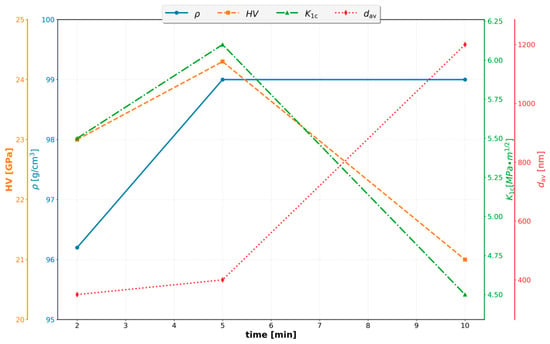
Due to the limited availability of powders, their high cost, and overall research expenses, it is unfeasible to carry out a full-factorial experimental design. In the production of sintered materials, process optimization is essential. Curve No. 3 shows a local maximum at 1400 °C, whereas the remaining curves do not exhibit any extrema. The results presented in Figure 1 confirm the necessity of expanding the scope of experimental research [37,43].
Figure 1.
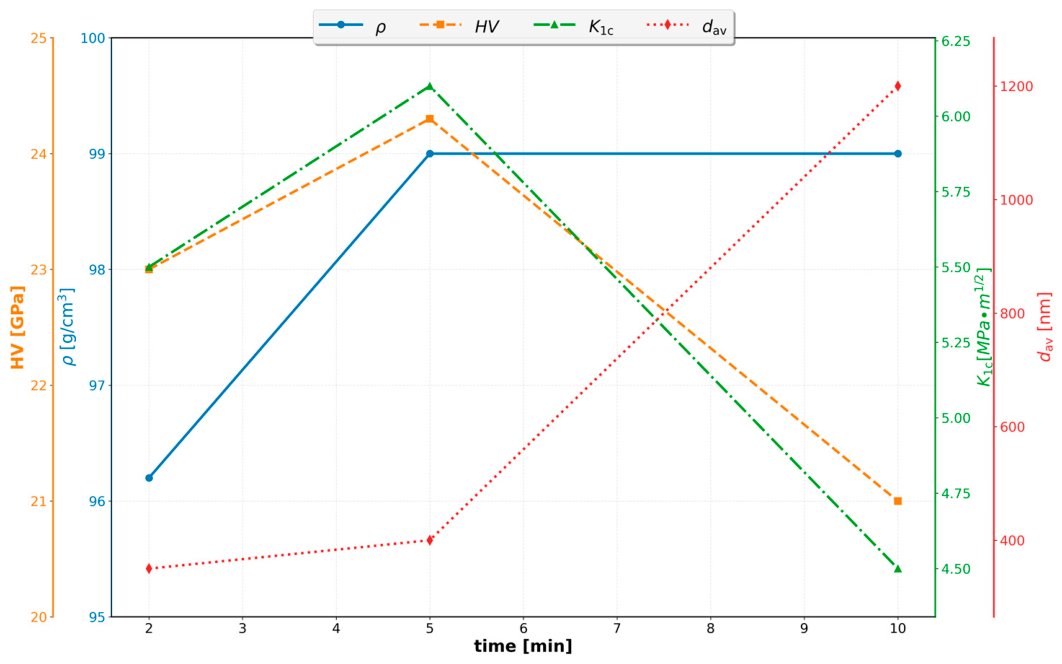
The effect of the holding time on the 3 mol% Y2O3-stabilized ZrO2 + 50 wt.% WC powder densification: grain size dav, fracture toughness KIC, density ρ, and hardness HV.
The findings presented by Hevorkian et al. further confirm that both sintering temperature and holding time significantly influence the properties of sintered materials [45]. Specifically, the sintering time has a substantial effect on fracture toughness and grain size [45].
The dominating grain size at 1730 °C is 0.42 µm, which increases to 0.75 µm at 1800 °C. Conversely, the flexural strength reaches a value of 720 MPa at 1730 °C and drops to 670 MPa at 1800 °C [44]. The effect of holding time on some physical and mechanical characteristics of the samples produced at T = 1700 °C and P = 40 MPa is shown in Figure 1 [45].
The relative density increases with rising temperature. For ZrO2, the relative density is approximately 92% at 1300 °C and reaches 98% at 1500 °C [46].
This manuscript addresses the physical construction and integration of an electroconsolidation machine for nanopowders, which utilizes a 50 Hz alternating current (AC) passing directly through the sintered material and the die under simultaneous mechanical pressing. The vast majority of existing literature on Spark Plasma Sintering (SPS) and Field-Assisted Sintering Technology (FAST) focuses almost exclusively on direct current (DC) or pulsed DC topologies. Consequently, this work deals with a highly unique and non-linear process dynamic. The prototype machine utilizes a high-power transformer; controlling such a system poses a significant engineering challenge due to magnetic saturation effects, transformer dead-time, and the exponential drop in electrical resistivity characteristic of advanced ceramic composites during high-temperature consolidation. The control methodologies for such specific processes remain highly underrepresented in the generally available literature.
This paper stands out from standard thermal control studies by providing a complete synthesis and experimental validation of the entire control loop. The described research introduces a dedicated anti-windup back-calculation strategy specifically tailored to handle the integration saturation limits (0–100%) of the thyristor power regulator. This directly contrasts with conventional PID controller implementations, which suffer from integral windup and subsequent temperature overshoots that can trigger detrimental microstructural thermal shocks and destroy the ceramic composite. Furthermore, a dedicated time-profile program control framework was designed to allow for free and precise execution of the heating rates for the sintered materials.
Therefore, this article carries distinct publication value as it delivers a verifiable, reproducible automation framework for high-power AC sintering equipment. The experimental results confirm that the proposed control strategy ensures strict process repeatability, which is mandatory to guarantee the microstructural homogeneity of tungsten carbide-zirconia (WC–ZrO2) composites.
2. Materials and Methods
2.1. Description of Sintering Machine
The electroconsolidation machine developed for this study is a prototype designed for continuous optimization based on iterative experimental feedback. The device integrates several key functional units: an alternating current (AC) power supply with an advanced control system, a vacuum chamber equipped with a vacuum pump, a structural frame, a hydraulic pressing unit for generating uniaxial pressure, and a cooling system. To ensure precision during the process, the machine is also equipped with a measurement and control system featuring high-speed data acquisition and recording modules.
The optimal technological parameters for this specific setup are currently being refined through extensive experimental campaigns. Preliminary findings and partial results regarding the consolidation efficiency of this method have been documented in several previous studies [13,18,39,45]. The comprehensive technical boundaries and design parameters of the developed AC electroconsolidation machine are summarized in Table 1. These target specifications were established based on an extensive literature review of Field-Assisted Sintering Techniques (FASTs) and the practical, long-term experimental expertise of our materials science research team regarding the consolidation of advanced ceramic nanocomposites.
Table 1.
The target technical specifications of the prototype machine established based on a literature review and institutional research experience.
The control system incorporates automated regulation units for both the temperature in the chamber (programmable regulation) and the pressing force (hydraulic press—programmable regulation). Furthermore, the control system enables the measurement and monitoring of the press punch displacement, vacuum control, cooling water flow control, and cooling water temperature.
Description of Control System. One of the primary objectives of our research team is to develop a cost-effective apparatus for the production of sintered advanced ceramics with properties that equal, or potentially surpass, those obtained via alternative consolidation methods. A key advantage of this machine lies in the simplicity of its construction. Crucially, the built apparatus provides full access for custom control algorithm implementation and direct control signal monitoring, which is of paramount importance when conducting research on novel advanced materials. In industrial settings, control performance requirements are often less stringent than in laboratory research, where precise regulation is vital for isolating and analyzing the fundamental mechanisms of the electroconsolidation process.
The monitoring and control architecture is structured as a hierarchical system. A master PC is utilized for high-level data visualization, process logging, and operator supervision, allowing the operator to input specific process parameters and oversee the entire sintering operation. This PC is interfaced with a Siemens S7-1200 Programmable Logic Controller (PLC) (Siemens AG, Munich, Germany), programmed via TIA Portal software (version V13, Siemens AG, Munich, Germany), which executes the supervisory control (master control) for the Revex power controller (CD Automation, Legnano, Italy). The Siemens PLC utilizes a dedicated PID control algorithm to directly regulate the process temperature, while simultaneously operating safety interlocks and managing auxiliary subsystem parameters, including vacuum levels, compaction force, and cooling water flow.
Managing this system presents a significant engineering challenge due to the complex physical dynamics inherent to alternating current (AC) electroconsolidation. To achieve high temperatures, the machine utilizes a specialized high-power transformer (180 A, 400 VAC) operating under phase and group control. The control difficulties are primarily driven by magnetic saturation effects, transformer dead-time, and the exponential drop in electrical resistivity characteristic of advanced ceramic composites during high-temperature consolidation.
To address these non-linear conditions, this work introduces a dedicated anti-windup back-calculation strategy specifically tailored to handle the integration saturation limits (0–100%) of the thyristor-based power regulator. This stands in sharp contrast to conventional PID implementations, which suffer from integral windup and subsequent temperature overshoots that can induce catastrophic microstructural thermal shock and destroy ceramic composites. Furthermore, a dedicated time-profile program control has been designed and implemented within the system, allowing for complete flexibility in defining and executing precise heating rates for the sintered materials.
Experimental results confirm that the proposed control strategy ensures high process repeatability, which is essential for achieving microstructural homogeneity in zirconia-based (ZrO2) composites. We expect that the developed system will provide excellent stability in industrial applications. A comprehensive validation of the control system will be conducted in future work to fully quantify its performance limits under diverse industrial environments. In the future, more advanced control frameworks will be investigated, including Internal Model Control (IMC) and Robust Control, with plans to also implement genetic algorithms and Machine Learning approaches.
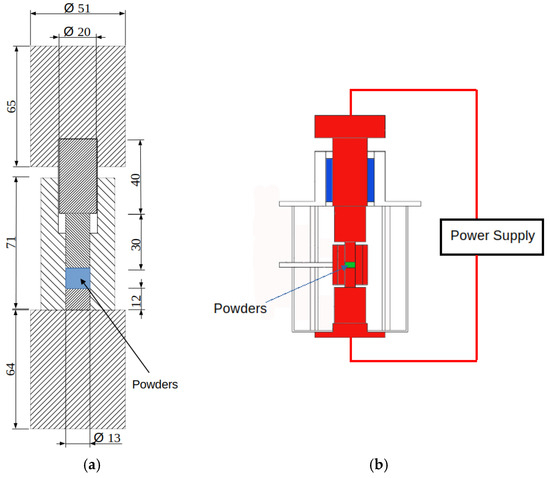
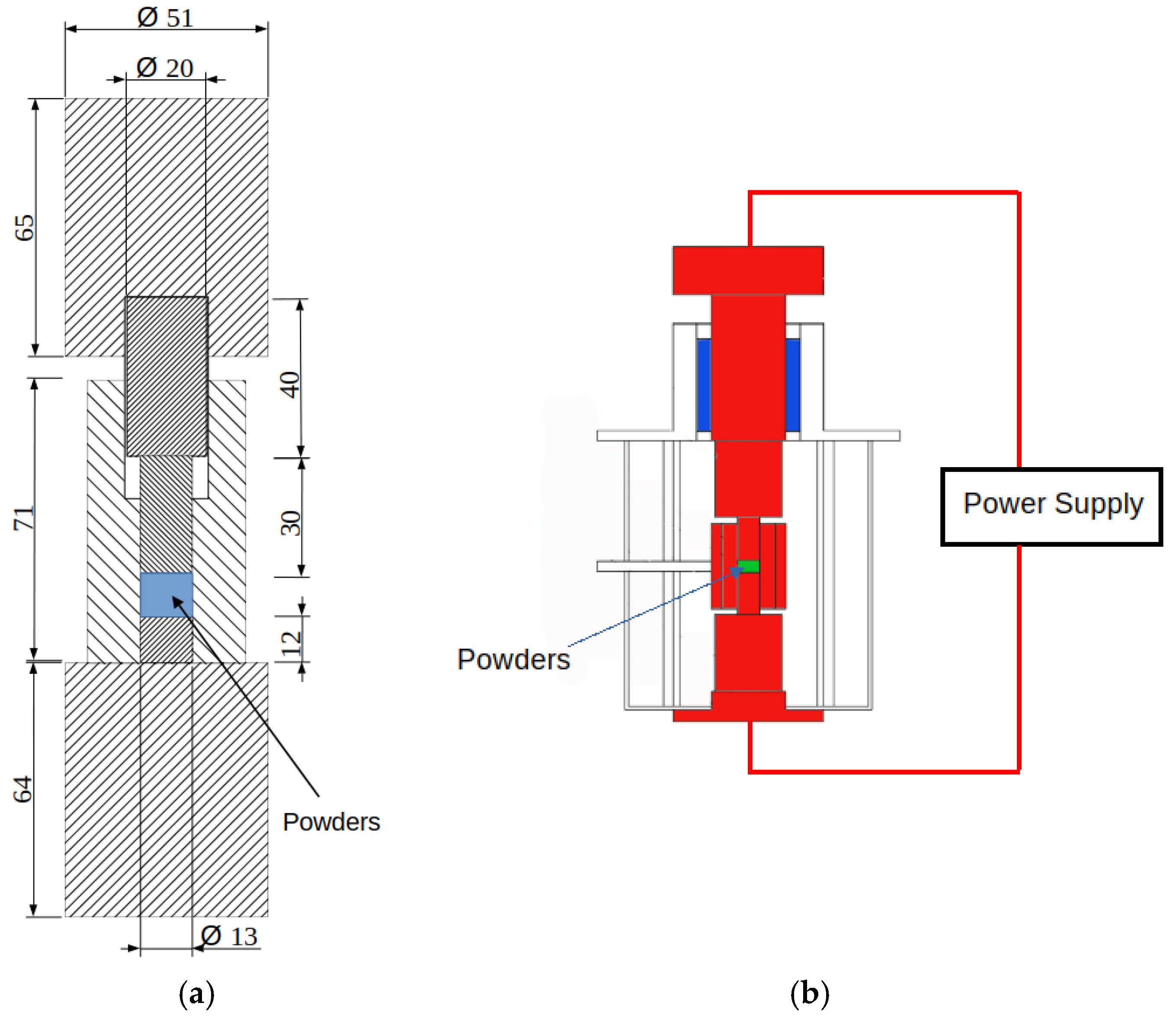
Heating Chamber and Die for Ceramic Sintering. The heating chamber used in this study was based on the conceptual design presented by Hevorkian et al. [18,45]. Figure 2 illustrates the die with dimensions used for the production of sintered materials. Specifically, the multi-component graphite die assembly has an outer diameter of 51 mm. It should be noted that during electroconsolidation, the total vertical dimension of the assembly decreases dynamically as compaction progresses. The presented heating chamber was utilized for modeling the sintering process. The machine is designed with an interchangeable heating chamber system; the design accounts for the future implementation of larger chambers for producing larger samples, which necessitated a higher power supply capacity in the prototype. The current prototype has provided the data necessary for the construction of a new control system and an upgraded heating chamber.
Figure 2.
Die (a) and schematic of sintering chamber (b). All dimensions in mm.
Sintering Temperature Control System. During the sintering stage, current flows through the powder within a regulation system according to the designed temperature program. Preliminary research and literature reviews indicated that a high-power supply unit, including a single-phase transformer with a current up to 180 A and inter-phase voltage on the primary side, is essential. The control unit is composed of two thyristors connected in an anti-parallel configuration. Due to the physical characteristics of thyristors, conduction continues until the voltage drops to zero, even if the gate signal is removed after activation [47]. The system includes overvoltage and short-circuit protections.
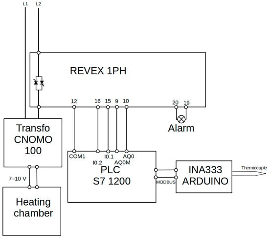
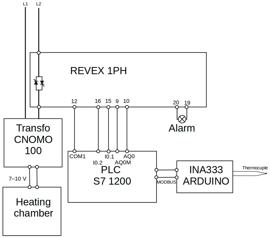
The hardware implementation (Figure 3) transfers energy from the L1 and L2 inter-phase connection through a REVEX 1PH power controller [48] (CD Automation, Legnano, Italy) to a CNOMO100 transformer [49] (ASPA, Wrocław, Poland), which then passes current through the die containing the material. The master temperature control is realized by a Siemens S7-1200 PLC (Siemens AG, Munich, Germany) with a programmed regulation system via TIA Portal software (version V13, Siemens AG, Munich, Germany).
Figure 3.
Hardware implementation of the sintering temperature control system.
The REVEX 1PH is a configurable single-phase power controller optimized for transformer primary loads. For communication and control, a 4–20 mA input is used. Various triggering modes will be tested: Single cycle, Half cycle, Burst, Phase angle, and Delayed triggering with adjustable ramps. The controller features dual current limits for peak or RMS values.
Construction of the Temperature Measurement Track. Temperature measurement is implemented using a thermocouple connected to an INA333 instrumentation amplifier and an Arduino Uno electronic system. Data are transmitted to the recording system via the MODBUS protocol. A review of the literature indicates that the sintering machine should generate high temperatures exceeding 1400 °C, with optimal sintering temperatures potentially reaching values above 2000 °C. Numerous studies have employed tungsten–rhenium thermocouples of the WRe5/20 (WRe5/26) type. These are high-temperature thermocouples (commonly referred to as Type C or W–Re), specifically designed for measuring extreme temperatures in vacuum, inert, or reducing atmospheres.
The characteristics of these thermocouples are defined in the international standard IEC 60584-1 [50], which is based on the International Temperature Scale of 1990 (ITS-90). In this standard, temperatures are expressed in degrees Celsius, while the electromotive force (emf) outputs are specified in microvolts (µV) with the reference junction maintained at 0 °C.
In the proposed control system, it was assumed that the thermoelectric voltage generated by the WRe(5/20) thermocouple would not exceed 30 mV. To amplify the measurement signal, a Texas Instruments INA333 micro-power (Texas Instruments, Dallas, TX, USA) (50 µA), zero-drift, rail-to-rail output instrumentation amplifier was used [51]. The INA333 compensates for internal offset voltage errors and features an exceptionally low input offset voltage (maximum 25 µV) and minimal offset drift over time and temperature (0.2 µV/°C). Additionally, the amplifier exhibits low noise performance and a rail-to-rail output capability, allowing the output voltage to approach within 0.05 V of the supply rails. This design feature increases the available dynamic range of the output signal. The gain G of the INA333 amplifier is defined by the following relationship [30]:
To achieve an output voltage of 5 V for an input voltage of 30 mV, the required gain is as follows:
Solving for the gain-setting resistor RG, the resulting value is approximately 603.6 Ω. In practice, the closest standard resistor value, 604 Ω from the E96 series, can be used.
PID Controller Tuning. The reliability of measurement results is heavily dependent on the reproducibility of the process conditions. Literature reviews and previous experimental studies have demonstrated that the temperature–time profile and the total sintering duration have a significant impact on the final properties of the material [12,26]. The heating rate depends on the step input value, which is implemented via the transformer control system using phase-angle or integral-cycle (group) control. At the beginning of the process, programmed control is executed. However, the core sintering phase is managed by a constant-value control system employing a PID (Proportional–Integral–Derivative) algorithm. The optimal parameters for the control algorithm depend on the specific sintering die (mold) geometry and the composition of the sintered materials (composite powders). The selection of these parameters was based on the step response characteristic of the process. For the tuning procedure, a First-Order Plus Dead Time (FOPDT) model was used along with the Cohen–Coon method [52]. Selecting PID settings using the Cohen–Coon method yields excellent results in cases where the system exhibits a significant delay relative to the time constant [53]. It is a modification of the Ziegler-Nichols method, which often provides superior control quality and reduced overshoots, particularly when the ratio of the transportation delay (τ) to the equivalent time constant (T) is small. To determine the controller settings, the following parameters are calculated from the open-loop step response [54,55,56]: km—the process gain, Tm—the effective time constant, and dm—the dead time (or lag).
The detailed calculations and the resulting values for these parameters, as applied to the experimental setup, are presented in the Section 3.
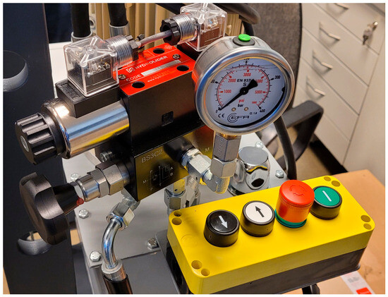
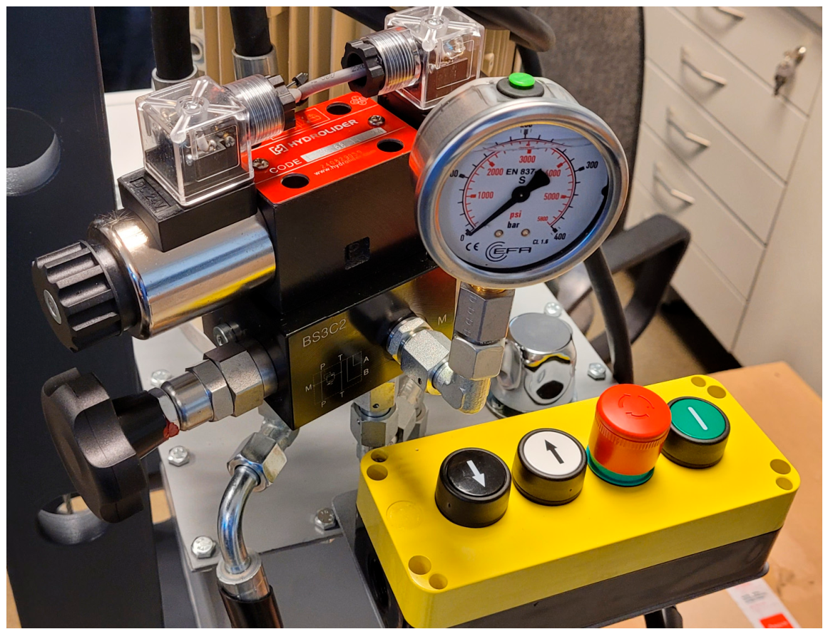
Hydraulic Press Description. A critical process parameter is the pressure applied between the upper and lower dies to create compressive stresses in the powders [18,39,57]. The pressing pressure is established by applying an adjustable force of up to 100 kN to the punches. In the current setup, a manual hydraulic press OTTO HS WWr 20 (OTTO, Słupsk, Poland) (OTTO, Słupsk, Poland) is utilized [58]. Currently, the pressure is controlled manually, though full automation with programmable regulation is planned for future iterations. The control and monitoring system for the hydraulic press is shown in Figure 4.
Figure 4.
Control and monitoring system for hydraulic press.
Vacuum Measurement System. Vacuum measurement is performed using an SMC ISE30A-01-C transducer [59] (SMC Corporation, Tokyo, Japan). This pressure transducer has a measurement range of −0.1 to 1 MPa. It features one digital output (triggered at a programmed setpoint) and one analog output (0.6 to 5 V) proportional to the measured pressure. Vacuum is maintained to ensure environmental reproducibility; while its value does not significantly affect material parameters, the measurement circuit implements an interlock system to verify experimental readiness and protect the WRe thermocouple from oxidation.
Sintered Sample Characterization. This manuscript describes the physical construction of the machine, with a particular focus on the control and measurement system designed for the sintering temperature. As representative analytical results, data are presented for a composite specimen with the following nominal composition: 50 wt.% ZrO2, 49.5 wt.% WC, and 0.5 wt.% graphene. The total mass of the sample was 6.5 g. The raw materials used exhibited a high purity of 99% for both WC and ZrO2. The carbon component was Graphene Nanopowder (C), 11–15 nm, Product #0544DX, Lot #0544-012916, supplied by SkySpring Nanomaterials, Inc. (Houston, TX, USA) The detailed powder preparation procedure has been comprehensively described in previous works [13,38]. The fabricated sample had a diameter of 13 mm, with a height of 12 mm before sintering and 5 mm after the consolidation process. The precise positioning of the thermocouple inside the graphite die was maintained at a distance of approximately 1 mm from the mold wall. To account for the friction force between the graphite punch and the inner wall of the die, which directly influences the actual pressure exerted on the powder, the force measurement system is fully calibrated every time the die assembly is replaced.
2.2. Thermal Model of Heating Chamber and Sintering Die
Process modeling is essential for the development of a robust process control algorithm. Modeling the temperature distribution within the chamber space allows for the analysis of its behavior over time, and time-series analysis can be effectively utilized to predict key process parameters. The temperature profile over time represents one of the most critical process variables [60,61,62]. Furthermore, a well-defined model enables accurate process simulations [63]. During the sintering process of nanopowders, high temperatures are generated, typically in the range of 1200–1700 °C. The dynamics of the heating process can be described using differential or difference equations, which yield either a continuous or discrete transfer function, respectively. This process can often be represented by a first-order or second-order model with delay. For practical purposes in automatic control systems, it is generally unnecessary to use higher-order models.
The First-Order Plus Dead Time (FOPDT) model describes systems where the output responds to an input change with both a time lag and delayed dynamics.
Differential Equation (Time Domain)
where y(t)—output variable, u(t − τ)—input (forcing) function delayed by time τ, T—time constant (T > 0), k—static gain, and τ—transportation delay (τ ≥ 0).
Transfer Function (Laplace Domain)
The term (k/(T·s + 1)) represents first-order inertial dynamics, while models the transportation delay. The exponential delay term makes the transfer function non-rational, which complicates control design.
Second-Order Inertial Process with Transportation Delay
where y(t)—output variable, u(t − τ)—delayed input, T1, T2—time constants (T1 > 0, T2 > 0), k—static gain, and τ—transportation delay (τ ≥ 0).
Transfer Function (Laplace Domain):
The discrete equivalents can be derived using the Zero-Order Hold (ZOH) method, with Tp denoting the sampling period [27,28].
1. First-Order Inertial Process with Delay (FOPDT)
Difference Equation:
Discrete Transfer Function:
2. Second-Order Inertial Process with Delay (SOPDT)
Difference Equation:
Discrete Transfer Function:
where y(k)—output at discrete time step k, u(k)—input at discrete time step k, Tp—sampling period, T, T1, T2—continuous-time constants, K—static gain, τ—transportation delay (continuous), and N—number of discrete delay steps (integer).
To determine the discrete transfer function from the continuous-time domain, the bilinear (trapezoidal) transformation method can be applied:
3. Results
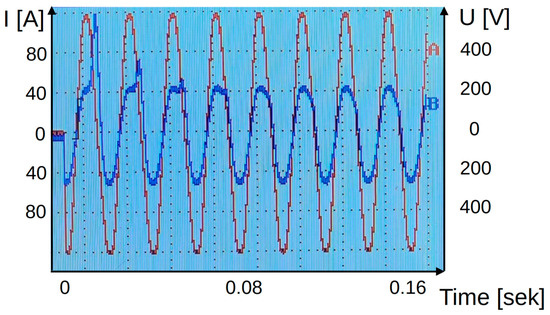
To limit the inrush current, phase-angle control can be applied. Nevertheless, a significant current spike may still occur during the activation of the control system (particularly in the first period of the waveform), which can be limited by adjusting the phase delay. Figure 5 shows the oscilloscope waveform with a 90° delay. The phase delay was selected experimentally; for the analyzed system, the optimal delay was found to be 70°.
Figure 5.
Inrush waveforms with a high inrush current value during the first cycle of the machine startup for (red) voltage and (blue) current.
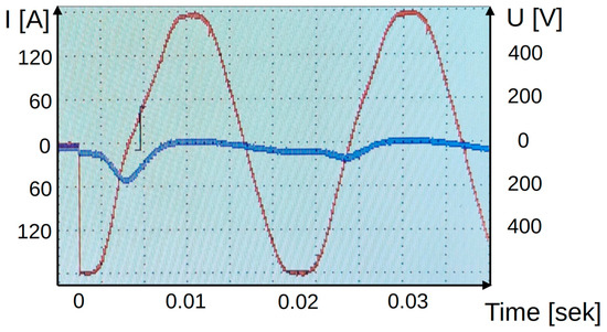
However, the selection of the delay may depend on various process parameters. This issue requires more detailed investigations, which is not the primary objective of the research presented in this manuscript. For example, Figure 6 illustrates the current and voltage waveforms in which an excessive current value does not occur, even for a phase shift of 90°.
Figure 6.
Inrush waveforms without an excessive inrush current value during the first cycle of the machine startup for (red) voltage and (blue) current.
3.1. Model of the Sintering Material Heating Process
Process identification was conducted based on experimental system measurements, whereby the open-loop step response characteristic was acquired. The input excitation constituted a step control signal of 45% magnitude, generated via burst firing control. The process output was temperature, recorded as the thermoelectric voltage of the thermocouple in millivolts [mV], omitting conversion into degrees Celsius.
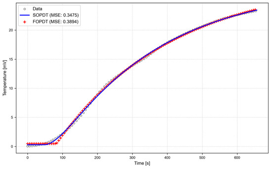
The model identification was performed using Python software (Version 3.12.3) by employing the non-linear least squares Levenberg–Marquardt algorithm. This optimization routine utilized the least squares criterion to estimate three fundamental parameters: the static gain (k), the time constant (T), and the transportation delay (τ). The transient response approximation was executed utilizing a First-Order Plus Dead Time (FOPDT) model structure, resulting in a mean squared error of MSE = 0.3894. The parametric identification yielded the following quantities: static gain (k) = 0.6250, time constant T = 332.6695 s, and transportation delay τ = 82.783 s. The continuous-time transfer function is expressed as follows:
Since the control system is digitally implemented, the discrete-time transfer function was derived, utilizing a sampling period of Ts = 3 s. The continuous-to-discrete time domain mapping was performed employing the Zero-Order Hold (ZOH) method. The resulting discrete-time transfer function, which constitutes a critical baseline for digital control system design, is formulated as follows:
The corresponding difference equation derived from this discrete-time transfer function is given by the following:
This model was subsequently utilized for controller parameter tuning using the Cohen–Coon method. For process control optimization, a Second-Order Plus Dead Time (SOPDT) model structure can also be employed, which yields a superior fit to the experimental data, with a mean squared error of MSE = 0.3475. However, this higher-order structure is incompatible with the analytical tuning rules of the Cohen–Coon method. Figure 7 illustrates the graphical comparison of the experimental data fitting obtained using both model structures.
Figure 7.
A graphical representation of the step response approximation using FOPDT and SOPDT models.
3.2. Selection of Controller Settings and Control System Simulation Results
The parameter tuning of the Proportional–Integral–Derivative (PID) controller was conducted utilizing the Cohen–Coon analytical method, based on the following identified plant parameters: K = 0.6250, T = 332.6695, and τ = 82.7830.
The Cohen–Coon method utilizes the ratio of the transportation delay to the dominant time constant (r = τ/T) to calculate the proportional gain (Kp), integral time (Ti), and derivative time (Td). This tuning technique is designed to provide high control performance with a well-defined transient response and a controlled overshoot. The analytical derivation of the PID controller parameters is presented below:
Using these calculated PID settings, simulation studies were performed to evaluate the dynamic tracking performance of the system for a constant setpoint of SP = 23 mV. The plant parameters identified from the experimental data collected during the actual electroconsolidation process, along with the calculated Cohen–Coon controller settings and the resulting dynamic performance indicators, are comprehensively summarized in Table 2.
Table 2.
Identified plant parameters, Cohen–Coon controller settings, and dynamic performance metrics of the temperature control system.
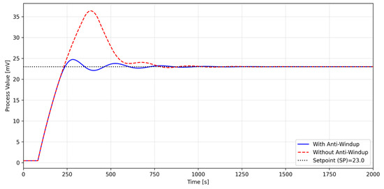
The comparative simulation analysis highlights a pronounced actuator saturation effect when the system operates without proper integration limits. As detailed in Table 2 and illustrated in Figure 8, the conventional PID controller configuration without anti-windup protection suffers from massive integral windup, leading to a catastrophic overshoot of 59.38% (ymax = 36.38 mV). In sharp contrast, the integration of the proposed anti-windup back-calculation strategy effectively mitigates this phenomenon, successfully suppressing the overshoot down to an acceptable value of just 7.66% (ymax = 24.73 mV).
Figure 8.
The transient response of the process output variable (temperature expressed as thermoelectric voltage in mV) for the control system implemented both with and without the anti-windup algorithm.
The obtained output variable waveforms for these two configurations confirm the dynamic operational efficiency of the anti-windup algorithm (indicated by the blue line in Figure 8).
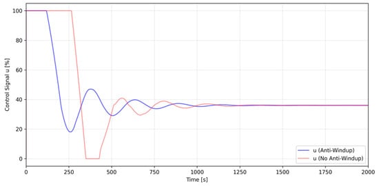
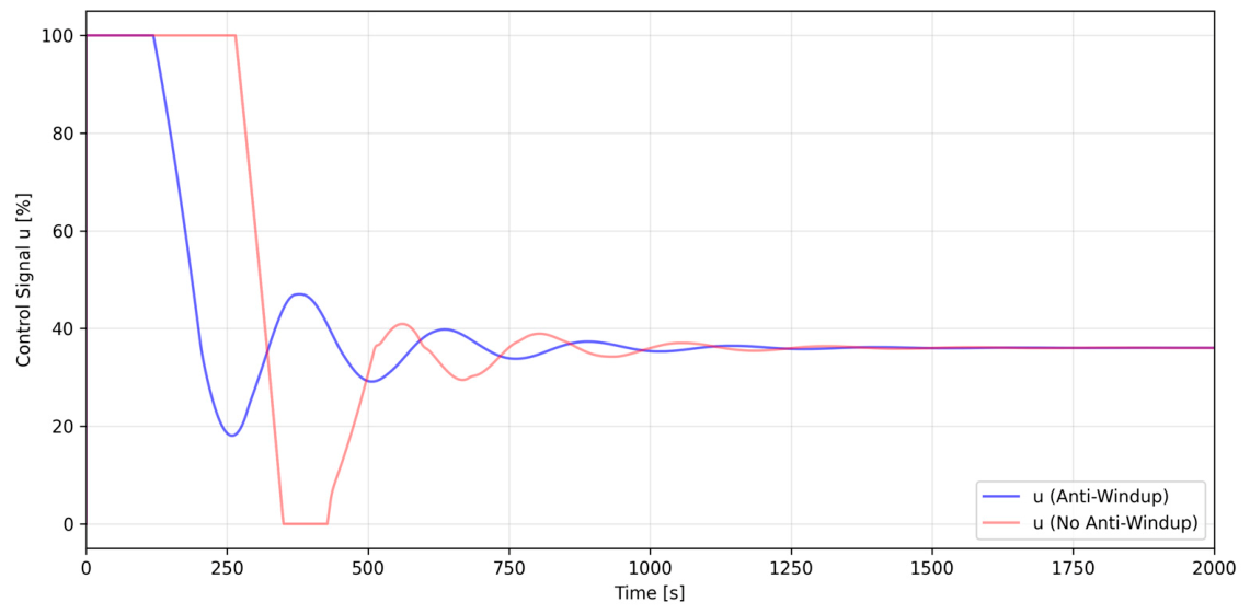
Another persistent challenge within the control system architecture concerns the behavior of the control signal profile (Figure 9). Immediately following system initialization and power activation, the control signal reaches 100% magnitude. Consequently, the thermal process is executed at the maximum possible rate of temperature rise (Figure 8).
Figure 9.
Control signal profiles obtained for the control system configuration implemented both without the anti-windup algorithm (red line) and with the anti-windup algorithm (blue line).
Such operating conditions are highly unfavorable, as tight regulation over the heating rate is strictly required [64]. Researchers intend to heat the specimens at varying, controlled rates to completely mitigate thermal shock phenomena. Furthermore, future investigations will evaluate the systematic influence of the temperature ramp rate on the final physical and mechanical properties of the sintered materials. To address these requirements, the control system was specifically engineered to execute precise heating rate control tasks.
During the primary phase, the heating process is conducted at a predetermined temperature rise rate by manually establishing a fixed control signal magnitude (configured at 45% of the burst firing control capacity in the analyzed case study). This specific baseline value is determined by the technologist in strict accordance with the experimental design matrix. Upon reaching the predefined setpoint (SP), the programmable control system automatically transitions into a constant-value regulation mode.
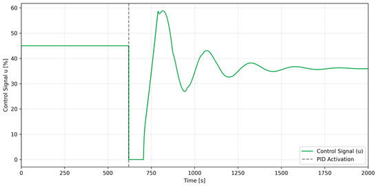
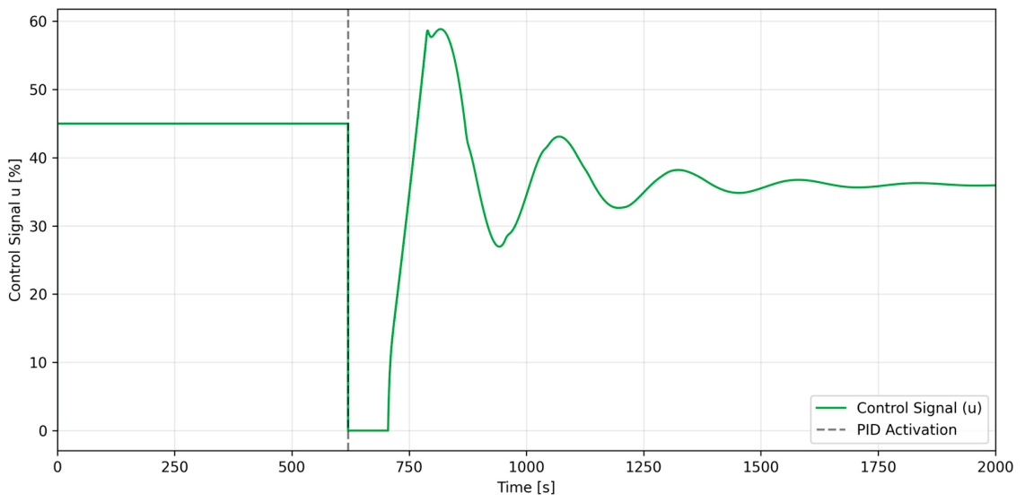
Unfortunately, this standard switching framework does not operate optimally. Large-amplitude step oscillations of the control signal (Figure 10) directly induce significant fluctuations in the process output variable (the thermoelectric voltage expressed in mV), as illustrated in Figure 11.
Figure 10.
Control signal profile in the programmable control mode without transportation delay compensation.
Figure 11.
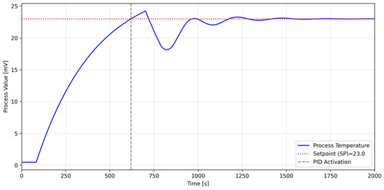
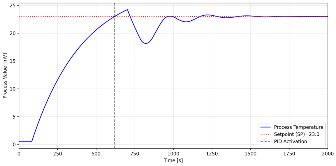
Temperature profile in the programmable control mode without transportation delay compensation.
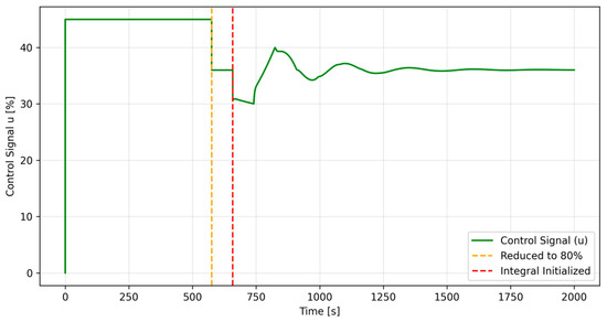
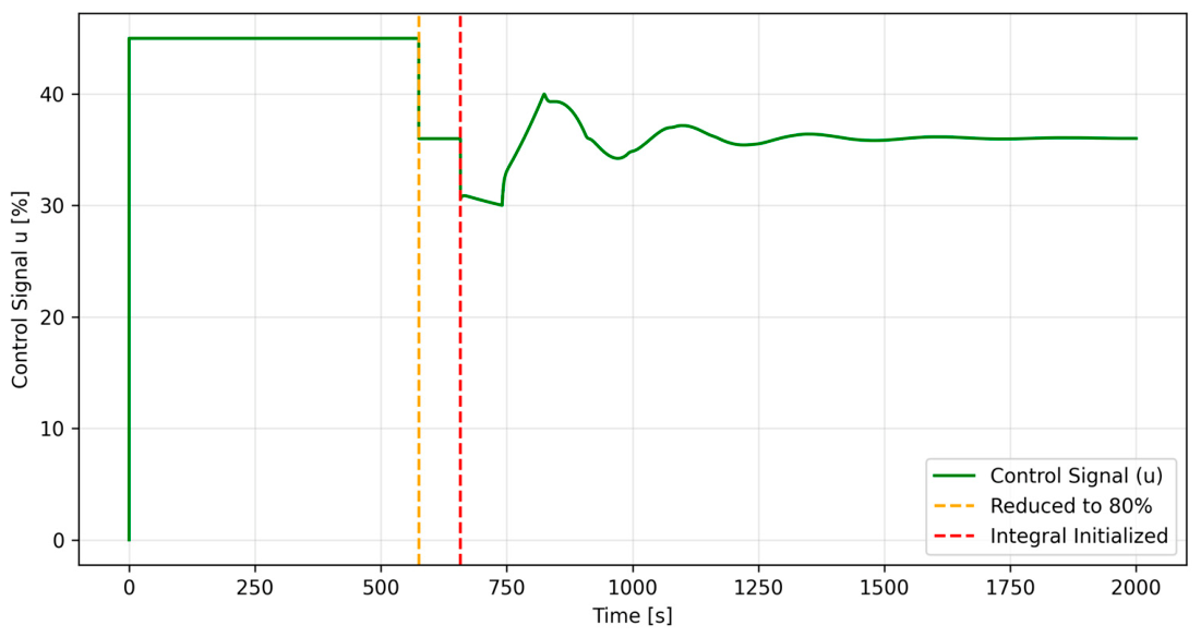
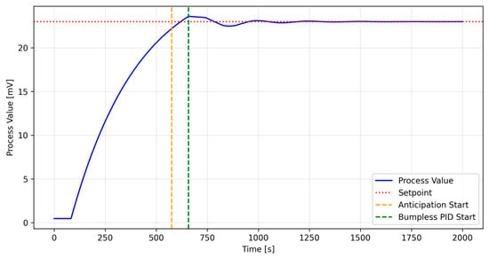
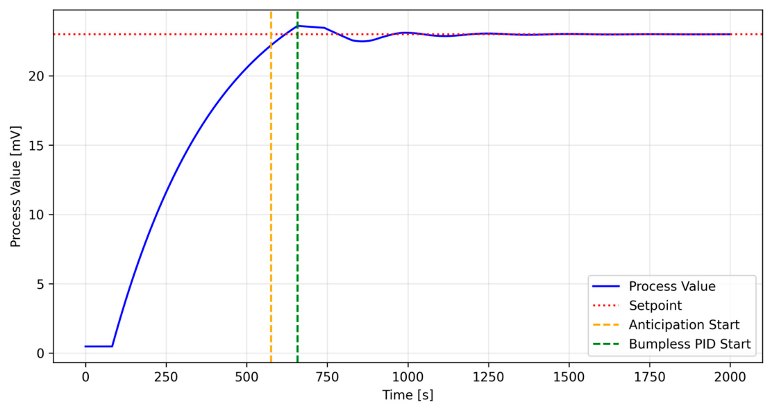
To eliminate these detrimental fluctuations, an advanced control framework was developed. During the dead time interval induced by the transportation delay, this system actively applies a dedicated control signal magnitude pre-calculated by the technologist (e.g., a reduction to 80% of the initial value, corresponding to the time frame bounded by the yellow and red vertical lines in Figure 12). This control signal reduction must be initiated with an appropriate lead time adjustment (demarcated by the yellow line in Figure 13) before the process variable successfully reaches the designated SP.
Figure 12.
Control signal profile in the programmable control mode with transportation delay compensation.
Figure 13.
Temperature profile in the programmable control mode with transportation delay compensation.
The operator configuration parameters, transition time intervals, and the resulting dynamic performance indicators obtained for the target setpoint of SP = 23 mV are organized and presented in Table 3.
Table 3.
Operator configuration, transition timing, and dynamic performance metrics for the advanced programmable control mode with transportation delay compensation.
As explicitly detailed in Table 3 and visually substantiated by the optimized transient profiles in Figure 12 and Figure 13, the advanced programmable framework yields a substantial reduction in process oscillations. By initiating the anticipation phase at t = 518 s (when the thermoelectric voltage hits the 21.0 mV trigger threshold), the system actively forces the control signal down to a steady-state holding capacity of uboost = 36.0%.
The measured holding phase duration (Delta tholding = 82.79 s) matches the plant’s structural transportation delay (dm = 82.782999 s verified in Table 2). This predictive lead-time adjustment completely counters the physical dead time of the heating chamber before engaging the full PID loop at t = 600 s. Consequently, this multi-stage strategy restricts the final maximum peak to ymax = 23.27 mV, achieving an overshoot of just 1.20%.
4. Discussion
In summary, the experimental and simulation results clearly demonstrate that temperature process control within this specific high-power alternating current (AC) electroconsolidation configuration is a complex, multivariable engineering challenge. Because experimental trials involving nanopowders are inherently cost-prohibitive, labor-intensive, and destructive to the graphite tooling setups, executing a full-factorial or comprehensive composite experimental design remains unfeasible. Therefore, relying on mathematical modeling and predictive simulation frameworks is the only viable path toward systematic process optimization.
A critical observation from the initial phase of this research involves the electrical startup dynamics of the system. As demonstrated by the oscilloscope waveforms in Figure 5 and Figure 6, the management of the inrush current during the first waveform period represents a non-linear phenomenon driven by the primary transformer magnetization and the initial contact resistance of the cold green compact. The experimental selection of an optimal 70° phase delay highlights that fixed triggering angles cannot universally mitigate magnetic saturation effects across diverse die configurations. This directly validates the necessity of integrating a flexible, dual-mode power controller (such as the REVEX 1PH) capable of transitioning between phase-angle and integral-cycle triggering modes as the thermal cycle progresses.
The simulation outcomes demonstrated the necessity of utilizing an advanced, multi-stage control system architecture rather than standard, out-of-the-box regulatory loops. The investigated plant cannot be treated as a simple linear system. Apart from exhibiting a substantial, time-varying transportation delay (dead time) of approximately 83 s, the system possesses distinct non-linear characteristics. This physical lag introduces a non-rational exponential delay term e−τs into the continuous transfer function, which reduces the phase margin of controllers.
During high-temperature consolidation, the non-linear behavior is heavily governed by the dynamic coupling between thermal and electrical fields. As the ZrO2-based ceramic matrix and the WC/graphene conductive phases densify, the electrical resistivity of the bulk material drops exponentially. This microstructural evolution creates a positive feedback loop: lower resistance increases local Joule heating efficiency under constant voltage conditions, which drastically alters the process dynamics in real time.
Furthermore, the model parameters are non-stationary. As the sintering temperature scales from ambient up toward the target zone exceeding 1400 °C, the structural gain k and the dominant time constant T shift continuously. This drift is caused by the shift from conductive heat transfer at lower stages to the exponential nature of radiative and convective heat losses at elevated temperatures. The comparative modeling approach (Figure 7) confirms that while a Second-Order Plus Dead Time (SOPDT) model provides a mathematically superior fit (MSE = 0.3475) by capturing the secondary thermal inertia of the surrounding insulation chamber, it lacks compatible analytical tuning expressions within classical frameworks. Consequently, the First-Order Plus Dead Time (FOPDT) structure remains the most viable baseline for analytical synthesis, despite introducing a minor approximation error (MSE = 0.3894).
The implementation of the classic Cohen–Coon tuning method combined with an anti-windup back-calculation strategy successfully resolved the actuator saturation limits (0–100%) inherent to thyristor power regulation. As illustrated in Figure 8 and Figure 9, a standard PID controller without windup protection causes temperature overshoots due to the accumulated integral action during the 83 s dead time interval. In advanced ceramic composites, such thermal overshoots are unacceptable, as the resulting localized thermal gradients trigger microstructural thermal shocks, promote detrimental grain growth (as reported in the literature), and induce cracking.
However, the major limitation of the current switching framework lies in its transient transition behavior. The severe control signal step oscillations observed in Figure 10 and the resulting temperature fluctuations in Figure 11 prove that standard constant-value regulation cannot smoothly handle the transition from a constant heating rate to a holding plateau. The development of the advanced transportation delay compensation framework (Figure 12 and Figure 13) represents a significant breakthrough in this study. By actively applying a pre-calculated control signal reduction (down to 80% magnitude) with a precise lead time adjustment before reaching the setpoint, the system successfully bypasses the dead time limitation, ensuring a seamless, stable transition.
Despite these excellent results, the practical viability of this multi-phase switching logic remains highly dependent on the operator’s extensive hands-on experience and intuitive knowledge of the specific material composition. The technologist must manually judge the optimal timing for the phase switching and estimate the pre-set holding power for each distinct die geometry. To eliminate this undesirable dependence on human expertise and to ensure absolute batch-to-batch microstructural homogeneity, future iterations of the research station must pivot toward autonomous, adaptive control frameworks.
Implementing a robust control framework or transitioning to the Skogestad Internal Model Control (SIMC) method [65] represents the logical next step. The SIMC approach is uniquely suited for this application because it uses a single tuning parameter—the desired closed-loop time constant—to systematically balance the trade-off between performance and robustness. This allows the automation framework to directly compensate for the exponential delay term without inducing high-frequency oscillations in the thyristor triggering system, ultimately securing a fully reproducible manufacturing framework for advanced ceramic nanocomposites. Such control methodologies will be investigated in future research should the need arise.
An analysis of the available literature establishes a direct, non-linear correlation between the fundamental consolidation parameters and the resulting mechanical performance of advanced ceramic matrix composites. Among these technological variables, the absolute temperature value, the real-time temperature–time trajectory, the sintering time, and the applied compressive stress act as the primary drivers governing microstructural evolution, phase stability, and grain growth kinetics. Consequently, achieving a high-precision thermal control framework is not merely an automation requirement, but a strict material science necessity to consistently secure target macro-properties such as optimized microhardness, high fracture toughness, and structural reliability.
In the context of the investigated alternating current (AC) electroconsolidation process under laboratory conditions, this dependency becomes even more critical. Standard industrial approaches often tolerate broad thermal margins; however, the highly unique coupling of simultaneous uniaxial compression and high-intensity cyclic current flow requires immediate transition-phase stability. Any uncompensated thermal lag or oscillation directly triggers localized potential gradients and inhomogeneous bulk diffusion. As demonstrated by the simulation data compiled in Table 2 and Table 3, conventional control paradigms fail, leading to massive overshoots (kappa = 59.38%) that cause microstructural degradation. Therefore, the implementation of predictive, model-based thermal profiling—validated by the exceptional reduction in the transient overshoot down to just 1.20% via the advanced transportation delay compensation framework—presents a vital methodological shift. This approach ensures that the tight kinetic boundaries necessary for manufacturing high-quality zirconia (ZrO2)-based nanocomposites are strictly maintained throughout the entire consolidation cycle.
5. Conclusions
The research presented in this manuscript comprehensively addresses the engineering challenges associated with the design and construction of a unique, high-power alternating current (AC) electroconsolidation prototype machine. The developed machine is designed for the electroconsolidation of zirconia-based ceramic nanopowders under uniaxial compression.
Based on the empirical findings, parametric modeling, and predictive simulations, the following major conclusions can be drawn:
- Material–Process Interdependency: Comprehensive literature and experimental analysis confirm that the real-time temperature–time profile acts as the primary governing factor dictating the microstructural evolution, grain growth kinetics, and resulting mechanical performance (including microhardness, fracture toughness, and flexural strength) of advanced ceramic composites. Precise thermal tracking is therefore mandatory to isolate fundamental consolidation mechanisms and ensure material structural integrity.
- System Non-Linearity and Non-Stationarity: The AC electroconsolidation plant exhibits highly non-linear and non-stationary dynamic characteristics. These are driven by the intense coupling of thermal and electrical fields, manifesting as an exponential drop in electrical resistivity as the green compact densifies, alongside a continuous shift in the process gain (km) and dominant time constant (Tm) due to radiative and convective heat losses at temperatures exceeding 1400 °C.
- Transportation Delay: The mechanical design of the heating chamber introduces a significant structural transportation delay (τ ≈ 83 s) due to the high thermal inertia of the graphite die and chamber assembly. The presence of this transportation delay (τ ≈ 83 s) alongside an equivalent process time constant of T ≈ 333 s significantly complicates process control.
- Efficacy of Anti-Windup Control: Comparative simulation analysis demonstrated that a conventional PID controller operating without saturation limits exhibits a massive overshoot of 59.38% (ymax = 36.3759 mV), which induces destructive microstructural thermal shocks. The application of an anti-windup strategy successfully mitigates actuator saturation limits (0–100%), suppressing the transient overshoot down to 7.66% (ymax = 24.7263 mV).
- Optimization via Programmable Control with Delay Compensation: The development of an advanced, multi-stage programmable control framework with predictive lead-time adjustment ensures the highest regulation quality. By actively forcing the control signal to a pre-calculated holding value (uboost = 36.0%) during the transition phase, this approach reduces switching oscillations, restricting the final process peak to ymax = 23.2707 mV and minimizing the overshoot to just 1.20%.
In conclusion, the developed automation framework provides a stable, verifiable, and reproducible manufacturing environment for advanced zirconia (ZrO2)-based nanocomposites. Future research will focus on transitioning this multi-phase switching logic into fully autonomous, adaptive control architectures—such as the Skogestad Internal Model Control (SIMC) method, genetic algorithms, and machine learning—to entirely eliminate operational dependence on human expertise and guarantee absolute batch-to-batch microstructural homogeneity across diverse industrial environments.
Funding
This research was funded by National Science Centre Poland, grant number 2022/47/B/ST5/01041.
Data Availability Statement
The original contributions presented in this study are included in the article. Further inquiries can be directed to the corresponding author.
Acknowledgments
I would like to thank the entire research team for their support and help with this project. Special thanks go to Edvin Hevorkian for his close collaboration and guidance, and to Volodymyr Chyshkala for his technical assistance during the experiments.
Conflicts of Interest
The author declares no conflict of interest.
Abbreviations
The following abbreviations are used in this manuscript:
| PLC | Programmable Logic Controller |
| FAST | Field-Assisted Sintering Techniques |
| SPS | Spark Plasma Sintering |
| PID | Proportional–Integral–Derivative |
| FOPDT | First-Order Plus Dead Time |
| SOPDT | Second-Order Inertial Process with Delay |
| SEM | scanning electron microscopy |
| XRD | X-ray diffraction |
References
- Tokita, M. Progress of Spark Plasma Sintering (SPS) Method, Systems, Ceramics Applications and Industrialization. Ceramics 2021, 4, 160–198. [Google Scholar] [CrossRef] [Scilit]
- Hu, Z.-Y.; Zhang, Z.-H.; Cheng, X.-W.; Wang, F.-C.; Zhang, Y.-F.; Li, S.-L. A Review of Multi-Physical Fields Induced Phenomena and Effects in Spark Plasma Sintering: Fundamentals and Applications. Mater. Des. 2020, 191, 108662. [Google Scholar] [CrossRef] [Scilit]
- Nakamoto, A.; Nambu, K.; Masuda, H.; Yoshida, H. Chemical Bonding and Crystal Structure in Flash Sintered Y2O3 under DC or AC Field. J. Eur. Ceram. Soc. 2023, 43, 3516–3523. [Google Scholar] [CrossRef] [Scilit]
- Conrad, H.; Yang, D. Effect of the Strength of an AC Electric Field Compared to DC on the Sintering Rate and Related Grain Size of Zirconia (3Y-TZP). Mater. Sci. Eng. A 2013, 559, 591–594. [Google Scholar] [CrossRef] [Scilit]
- Cao, C.; Mücke, R.; Guillon, O. Effect of AC Field on Uniaxial Viscosity and Sintering Stress of Ceria. Acta Mater. 2020, 182, 77–86. [Google Scholar] [CrossRef] [Scilit]
- Stojanovic, B.; Glisovic, J. Application of Ceramic Matrix Composite in Automotive Industry. In Encyclopedia of Materials: Composites; Brabazon, D., Ed.; Elsevier: Oxford, UK, 2021; pp. 275–292. [Google Scholar]
- Luo, N.; Lin, Y.; Guo, J.; Quattrocchi, E.; Deng, H.; Dong, J.; Ciucci, F.; Boi, F.; Hu, C.; Grasso, S. Spark Plasma Sintering of LiFePO4: AC Field Suppressing Lithium Migration. Materials 2021, 14, 2826. [Google Scholar] [CrossRef] [Scilit] [PubMed]
- Nieroda, P.; Kruszewski, M.J.; Leszczyński, J.; Mars, K.; Koleżyński, A. Influence of DC and AC Current in the SPS Sintering Process on Homogeneity of Thermoelectric Properties of Cu2S and Cu2Se. Ceram. Int. 2023, 49, 9681–9690. [Google Scholar] [CrossRef] [Scilit]
- Song, S.-X.; Wang, Z.; Shi, G.-P. Heating Mechanism of Spark Plasma Sintering. Ceram. Int. 2013, 39, 1393–1396. [Google Scholar] [CrossRef] [Scilit]
- Hebda, M. Spark Plasma Sintering–Nowa Technologia Konsolidacji Materiałów Proszkowych. Czas. Tech. Mech. 2012, 109, 47–55. [Google Scholar]
- Ingraci Neto, R.R.; McClellan, K.J.; Byler, D.D.; Kardoulaki, E. Controlled Current-Rate AC Flash Sintering of Uranium Dioxide. J. Nucl. Mater. 2021, 547, 152780. [Google Scholar] [CrossRef] [Scilit]
- Wang, X.-H.; Chen, I.-W. Sintering of Nano-Ceramics. In Nanomaterials Handbook; CRC Press: Boca Raton, FL, USA, 2017. [Google Scholar]
- Rucki, M.; Hevorkian, E.; Latosińska, J.N.; Kolodnitskyi, V.; Chalko, L.; Morozow, D.; Samociuk, W.; Matijosius, J.; Masař, M.; Ryba, T. Reproducibility Assessment of Zirconia-Based Ceramics Fabricated out of Nanopowders by Electroconsolidation Method. Appl. Sci. 2025, 15, 4955. [Google Scholar] [CrossRef] [Scilit]
- Munir, Z.A.; Quach, D.V.; Ohyanagi, M. Electric Current Activation of Sintering: A Review of the Pulsed Electric Current Sintering Process. J. Am. Ceram. Soc. 2011, 94, 1–19. [Google Scholar] [CrossRef] [Scilit]
- Su, X.; Jia, Y.; Han, C.; Hu, Y.; Fu, Z.; Liu, K.; Yu, Y.; Yan, X.; Wang, Y. Flash Sintering of Lead Zirconate Titanate Ceramics under an Alternating Current Electrical Field. Ceram. Int. 2019, 45, 5168–5173. [Google Scholar] [CrossRef] [Scilit]
- Liu, J.; Li, X.; Wang, X.; Huang, R.; Jia, Z. Alternating Current Field Flash Sintering 99% Relative Density ZnO Ceramics at Room Temperature. Scr. Mater. 2020, 176, 28–31. [Google Scholar] [CrossRef] [Scilit]
- Yan, N.; Zhu, Y.; Cai, M.; Li, B.; Xu, B.; Li, Y.; Wang, X.; Jia, Z. Reactive Flash Sintering of High-Entropy Oxide (Mg, Co, Ni, Cu, Zn)1−xLixO at Room Temperature. Materials 2022, 15, 3836. [Google Scholar] [CrossRef] [Scilit] [PubMed]
- Hevorkian, E.S.; Nerubatskyi, V.P.; Chyshkala, V.O.; Lytovchenko, S.V.; Prokopiv, M.M.; Samociuk, W.; Mechnik, V.A. Technological and Innovative Features of the Electroconsolidation Method as a Kind of Plasma Sintering for Refractory Compounds. J. Superhard Mater. 2024, 46, 364–375. [Google Scholar] [CrossRef] [Scilit]
- Gil-González, E.; Manchón-Gordón, A.F.; Perejón, A.; Sánchez-Jiménez, P.E.; Pérez-Maqueda, L.A. Plasma-Flash Sintering II: Flashing ZnO at Room Temperature Using Low AC Voltage. J. Am. Ceram. Soc. 2025, 108, e70129. [Google Scholar] [CrossRef] [Scilit]
- Phuah, X.L.; Yang, B.; Charalambous, H.; Tsakalakos, T.; Zhang, X.; Wang, H. Microstructure and Defect Gradients in DC and AC Flash Sintered ZnO. Ceram. Int. 2021, 47, 28596–28602. [Google Scholar] [CrossRef] [Scilit]
- Krzysiak, Z.; Samociuk, W.; Bartnik, G.; Plizga, K.; Dziki, D.; Kaliniewicz, Z.; Nieoczym, A.; Wyciszkiewicz, A.; Otto, T. Analysis of Tank Safety with Propane-Butane on LPG Distribution Station. Pol. J. Chem. Technol. 2017, 19, 99–102. [Google Scholar] [CrossRef] [Scilit]
- Samociuk, W. Ryzyko Wystąpienia Poważnej Awarii Reaktora Syntezy Mocznika. Przem. Chem. 2017, 1, 149–152. [Google Scholar] [CrossRef] [Scilit]
- Wolszczak, P.; Samociuk, W. The Control System of the Yeast Drying Process. MATEC Web Conf. 2018, 241, 01022. [Google Scholar] [CrossRef] [Scilit]
- Wolszczak, P.; Lonkwic, P.; Cunha, A.; Litak, G.; Molski, S. Robust Optimization and Uncertainty Quantification in the Nonlinear Mechanics of an Elevator Brake System. Meccanica 2019, 54, 1057–1069. [Google Scholar] [CrossRef] [Scilit]
- Nisar, F.; Rojek, J.; Nosewicz, S.; Kaszyca, K.; Chmielewski, M. Coupled Thermo-Electric Discrete Element Model for Spark Plasma Sintering. Powder Technol. 2025, 458, 120957. [Google Scholar] [CrossRef] [Scilit]
- Yu, M.; Grasso, S.; Mckinnon, R.; Saunders, T.; Reece, M.J. Review of Flash Sintering: Materials, Mechanisms and Modelling. Adv. Appl. Ceram. 2017, 116, 24–60. [Google Scholar] [CrossRef] [Scilit]
- Tarnowski, W.; Ciebielski, M.; Bartkiewicz, S. Modelowanie Matematyczne i Symulacja Komputerowa Dynamicznych Procesów Ciągłych; Wydawnictwo Uczelniane PK: Koszalin, Poland, 2003. [Google Scholar]
- Bożek, A.; Trybus, L. Reduced gain pi/pid controllers for foptd/soptd processes under load disturbance. Acta Mech. Autom. 2024, 18, 212–222. [Google Scholar]
- Ratov, B.T.; Mechnik, V.A.; Bondarenko, N.A.; Hevorkian, E.S.; Kolodnitskyi, V.M.; Prikhna, T.A.; Moshchil, V.E.; Kalzhanova, A.B.; Sundetova, P.S.; Utepov, Z.G. Physicomechanical Properties of the Matrix Material of Cdiamond–(Fe–Cr–Cu–Ni–Sn) Composite Materials Formed by Spark Plasma Sintering. J. Superhard Mater. 2025, 47, 9–19. [Google Scholar] [CrossRef] [Scilit]
- Chen, P.; Miao, K.; Li, R.; Fan, G.; Wu, H. An In-Situ Three-Dimensional Study of the Dynamic and Mechanism during Spark Plasma Sintering of Aluminum Alloys. J. Mater. Sci. Technol. 2025, 219, 113–123. [Google Scholar] [CrossRef] [Scilit]
- Wang, C.; Li, Y.; Zhang, W.; Zhao, T.; Du, H. Effect of Temperature on the Microstructure and Mechanical Properties of TiC/Fe Matrix Composites Fabricated by Spark Plasma Sintering. J. Mater. Res. Technol. 2024, 33, 1032–1047. [Google Scholar] [CrossRef] [Scilit]
- Liu, Z.; Chen, T.; Yang, Y.; Song, T.; Cai, W.S.; Ke, H.B.; Wang, W.H.; Yang, C. A New Method for Determining Activation Energy in Spark Plasma Sintering. Powder Technol. 2025, 449, 120367. [Google Scholar] [CrossRef] [Scilit]
- Arif, M.; Han, D.; Shin, W.; Cha, S.; Pak, C.; Kim, Y.; Kim, S.; Lee, B.; Rhyee, J. Ultra-Low Core Loss and High-Frequency Permeability Stability in Hot-Press Sintered FeSi Soft Magnetic Composites by Fe2O3 Nanoparticles Air Gap Filling. Materials 2025, 18, 2013. [Google Scholar] [CrossRef] [Scilit] [PubMed]
- Zhang, Y.; Nie, J.; Chan, J.M.; Luo, J. Probing the Densification Mechanisms during Flash Sintering of ZnO. Acta Mater. 2017, 125, 465–475. [Google Scholar] [CrossRef] [Scilit]
- Samociuk, W.; Hevorkian, E.; Prikhna, T.; Chishkala, V.; Mamalis, A.; Rucki, M. Peculiarities of Yttria- and Ceria-Stabilized Zirconia Ceramics Fabricated via Electroconsolidation. Materials 2026, 19, 776. [Google Scholar] [CrossRef] [Scilit] [PubMed]
- Liu, Z.; He, Z.; Li, Z.; Chen, S.; Cheng, L.; Zhao, X.; Zhao, X.; Yin, G.; Yan, N.; Liu, J.; et al. Large-Diameter Ceramic Room-Temperature Flash Sintering Technology Based on New Carbon Electrodes. J. Adv. Ceram. 2025, 14, 9221094. [Google Scholar] [CrossRef] [Scilit]
- Gevorkyan, E.S.; Nerubatskyi, V.P. Technological and Scientific Aspects of Consolidation of Refractory Composites; LLC “Voskhod-Print”: Kharkiv, Ukraine, 2022. [Google Scholar]
- Ivzhenko, V.; Hevorkian, E.; Rucki, M.; Nerubatskyi, V.; Krzysiak, Z.; Chyshkala, V.; Latosińska, J.N.; Samociuk, W.; Szumiata, T.; Kosenchuk, T.; et al. Improvement of Microstructure and Mechanical Properties of SiC–VC System Obtained by Electroconsolidation. Materials 2025, 18, 4331. [Google Scholar] [CrossRef] [Scilit] [PubMed]
- Hevorkian, E.; Michalczewski, R.; Rucki, M.; Sofronov, D.; Osuch-Słomka, E.; Nerubatskyi, V.; Krzysiak, Z.; Latosińska, J.N. Effect of the Sintering Parameters on the Structure and Mechanical Properties of Zirconia-Based Ceramics. Ceram. Int. 2024, 50, 35226–35235. [Google Scholar] [CrossRef] [Scilit]
- Liu, L.; Li, J.; Morita, K.; Kim, B.-N.; Suzuki, T.S. Enhanced Optical Properties of Translucent YVO4 Ceramic Fabricated by Spark-Plasma-Sintering (SPS) via Texture-Controlled Microstructure. Opt. Express 2025, 33, 16976–16986. [Google Scholar] [CrossRef] [Scilit] [PubMed]
- Adamovic, D.; Zivic, F. Hardness and Non-Destructive Testing (NDT) of Ceramic Matrix Composites (CMCs). In Encyclopedia of Materials: Composites; Brabazon, D., Ed.; Elsevier: Oxford, UK, 2021; Volume 2, pp. 183–201. [Google Scholar] [CrossRef] [Scilit]
- Quinn, G.D. Fracture Toughness of Ceramics by the Vickers Indentation Crack Length Method: A Critical Review. In Mechanical Properties and Performance of Engineering Ceramics II: Ceramic Engineering and Science Proceedings; John Wiley & Sons, Ltd.: Hoboken, NJ, USA, 2006; pp. 45–62. [Google Scholar]
- Hevorkian, E.; Jozwik, J.; Rucki, M.; Kolodnitskyi, V.; Morozova, O.; Dziedzic, K. Reproducibility of Properties of the Zirconia-Based Composites. In Proceedings of the 2024 11th International Workshop on Metrology for AeroSpace (MetroAeroSpace), Lublin, Poland, 3–5 June 2024; pp. 484–489. [Google Scholar]
- Gevorkyan, E.; Lavrynenko, S.; Rucki, M.; Siemiątkowski, Z.; Kislitsa, M. Preparation of Nanostructured Materials by Electrical Sintering. In Proceedings of the 7th International Conference on Mechanics and Materials in Design (M2D2017), Albufeira, Portugal, 11–15 June 2017; pp. 11–15. [Google Scholar]
- Hevorkian, E.S.; Nerubatskyi, V.P.; Rucki, M.; Kilikevicius, A.; Mamalis, A.G.; Samociuk, W.; Morozow, D. Electroconsolidation Method for Fabrication of Fine-Dispersed High-Density Ceramics. Nanotechnol. Percept. 2024, 20, 100–113. [Google Scholar]
- Gevorkyan, E.S.; Sofronov, D.S.; Nerubatskyi, V.P.; Chyshkala, V.O.; Morozova, O.M.; Lebedynskyi, O.M.; Mateychenko, P.V. A Study on the Formation and Sintering of Powders Synthesized from ZrO2 Micro- and Nanoparticles from Fluoride Solutions. J. Superhard Mater. 2023, 45, 31–45. [Google Scholar] [CrossRef] [Scilit]
- What Is a Thyristor Unit—CD Automation. Available online: https://www.cdautomation.com/what-is-a-thyristor-unit/ (accessed on 29 January 2026).
- REVEX 1PH—The Power Controller on Demand—CD Automation. Available online: https://www.cdautomation.com/product/revex-1ph-the-power-controller-on-demand/ (accessed on 29 January 2026).
- Transformatory. Available online: https://www.aspa.pl/pl/czesci-zamienne/transformatory/ (accessed on 29 January 2026).
- INA333 Data Sheet, Product Information and Support|TI.Com. Available online: https://www.ti.com/product/INA333 (accessed on 15 June 2026).
- Bhardwaj, L.; Mishra, A.; Asija, D. Parameter Optimisation of PID Controller Utilised for Speed Control of DC Motor with Ziegler-Nichols and Cohen-Coon Tuning Method. In Intelligent and Sustainable Power and Energy Systems; CRC Press: Boca Raton, FL, USA, 2025. [Google Scholar]
- Joseph, E. Cohen-Coon PID Tuning Method; A Better Option to Ziegler Nichols-PID Tuning Method. Comput. Eng. Intell. Syst. 2018, 9, 33–37. [Google Scholar]
- Taşören, A.E. Design and Realization of Online Auto Tuning PID Controller Based on Cohen-Coon Method. Avrupa Bilim Teknol. Derg. 2021, 24, 234–239. [Google Scholar] [CrossRef] [Scilit]
- Cohen, G.H.; Coon, G.A. Theoretical Consideration of Retarded Control. Trans. Am. Soc. Mech. Eng. 1953, 75, 827–834. [Google Scholar] [CrossRef] [Scilit]
- Cohen-Coon Autotuning Method—NI. Available online: https://www.ni.com/docs/en-US/bundle/labview/page/cohen-coon-autotuning-method.html (accessed on 6 November 2025).
- Gumilang, R.F.; Amalia, S.; Anugrah, A.; Bandri, S. Analisa Perbandingan Kontroler PID Terhadap Motor BLDC Menggunakan Penalaran Cohen-Coon Dan Trial & Error. Ranah Res. J. Multidiscip. Res. Dev. 2023, 5, 219–228. [Google Scholar] [CrossRef] [Scilit]
- Gevorkyan, E.; Mechnik, V.; Bondarenko, N.; Vovk, R.; Lytovchenko, S.; Chishkala, V.; Melnik, O. Peculiarities of Obtaining Diamond-(Fe-Cu-Ni-Sn) Composite Materials by Hot Pressing. Funct. Mater. 2017, 24, 31–45. [Google Scholar]
- Prasa Hydrauliczna OTTO HS WWr 20—Ręczna, Nacisk 20 ton. Available online: https://lewor.pl/otto-hs-wwr-20 (accessed on 31 January 2026).
- ISE30A, 2 Colour Display High-Precision Digital Pressure Switch for Positive Pressure. Available online: https://www.smc.eu/en-eu/search?searchTerm=ISE30A (accessed on 30 January 2026).
- Vovk, R.V.; Samociuk, W.; Hevorkian, E.S.; Nerubatskyi, V.P.; Chyshkala, V.O.; Komarova, H.L.; Voloshyna, L.V. Modeling of Density Estimation during Sintering of Zirconium Dioxide by the Method of Electroconsolidation. Low Temp. Phys. 2026, 52, 510–516. [Google Scholar] [CrossRef] [Scilit]
- Ratov, B.T.; Mechnik, V.A.; Bondarenko, N.A.; Kolodnitskyi, V.M.; Gevorkyan, E.S.; Nerubaskyi, V.P.; Gusmanova, A.G.; Fedorov, B.V.; Kaldibaev, N.A.; Arshidinova, M.T.; et al. Features Structure of the Cdiamond–(WC–Co)–ZrO2 Composite Fracture Surface as a Result of Impact Loading. J. Superhard Mater. 2023, 45, 348–359. [Google Scholar] [CrossRef] [Scilit]
- Vanmeensel, K.; Laptev, A.; Hennicke, J.; Vleugels, J.; Van der Biest, O. Modelling of the Temperature Distribution during Field Assisted Sintering. Acta Mater. 2005, 53, 4379–4388. [Google Scholar] [CrossRef] [Scilit]
- McWilliams, B.; Zavaliangos, A. Multi-Phenomena Simulation of Electric Field Assisted Sintering. J. Mater. Sci. 2008, 43, 5031–5035. [Google Scholar] [CrossRef] [Scilit]
- Phuah, X.L.; Wang, H.; Charalambous, H.; Jha, S.K.; Tsakalakos, T.; Zhang, X.; Wang, H. Comparison of the Grain Growth Behavior and Defect Structures of Flash Sintered ZnO with and without Controlled Current Ramp. Scr. Mater. 2019, 162, 251–255. [Google Scholar] [CrossRef] [Scilit]
- Skogestad, S. Simple Analytic Rules for Model Reduction and PID Controller Tuning. Model. Identif. Control 2004, 25, 85–120. [Google Scholar] [CrossRef] [Scilit]

Disclaimer/Publisher’s Note: The statements, opinions and data contained in all publications are solely those of the individual author(s) and contributor(s) and not of MDPI and/or the editor(s). MDPI and/or the editor(s) disclaim responsibility for any injury to people or property resulting from any ideas, methods, instructions or products referred to in the content. |
© 2026 by the author. Licensee MDPI, Basel, Switzerland. This article is an open access article distributed under the terms and conditions of the Creative Commons Attribution (CC BY) license.