


Abstract
In this study, the effects of stator winding inter-turn short-circuit faults occurring in an Axial Flux Synchronous Reluctance Motor (AF-SynRM) on motor performance were experimentally investigated. Within the scope of the study, a total of 12 different fault scenarios were created using different fault ratios and fault resistances, and the experiments were carried out under 4 different speed conditions and 5 different load conditions. In the analyses, phase current, fault current, power factor, and MTPA angle behaviors were evaluated. The obtained results demonstrated that significant increases in motor currents occurred particularly under low fault resistance and high load conditions. In addition, it was determined that the faults caused variations in power factor characteristic, while the MTPA angle, which represents the optimum operating point of the motor, shifted depending on the fault severity. Overall, the results revealed that stator winding inter-turn short-circuit faults (SITF) affect not only current levels but also energy conversion performance and control characteristics of the motor. As the first study in the literature to experimentally investigate the effects of SITF in an AF-SynRM structure within this scope, it is considered that the findings obtained will provide significant contributions to fault analysis and fault-tolerant drive systems.
1. Introduction
The continuous increase in global energy demand and the rapid depletion of fossil fuel resources have made energy efficiency one of the most important research topics in the field of electrical engineering. Since a significant portion of industrial electrical energy consumption is attributed to electric motors, the concepts of efficiency, power density, reliability, and sustainability have become critical in electrical machines [1,2]. Therefore, in recent years, studies on motor technologies capable of providing high efficiency, low cost, and environmental sustainability have increased significantly. In this context, Synchronous Reluctance Motors (SynRMs) have emerged as a strong alternative to conventional induction motors due to the absence of permanent magnets or rotor windings in their rotor structures, low rotor losses, simple manufacturing structures, and high efficiency potential. Furthermore, the fact that they do not require rare-earth elements makes SynRM technology an economical and sustainable solution [3,4,5].
Although conventional radial flux motors are widely used in industry, interest in Axial Flux (AF) motor topologies has been steadily increasing, particularly for applications requiring high torque density and compact structures. AF motors provide significant advantages in fields such as electric vehicles, aerospace systems, robotic applications, and high-performance industrial drives due to their high torque-to-volume ratio, short magnetic flux path, high power density, and compact geometric structure [6,7,8]. As a result of combining these advantages with SynRM technology, the Axial Flux Synchronous Reluctance Motor (AF-SynRM) has recently begun to attract attention in both academic and industrial studies. Although AF-SynRMs involve certain challenges in terms of manufacturing, mechanical assembly, and magnetic design, their high efficiency and high torque density characteristics make them a strong alternative for next-generation electric drive systems [9,10,11].
Electrical machines operating under industrial conditions are exposed to many adverse effects such as thermal stresses, overcurrent, vibration, humidity, voltage imbalances, and aging insulation. Over time, these conditions lead to the occurrence of electrical and mechanical faults, reducing system reliability and causing unplanned shutdowns and significant economic losses [12,13,14]. Studies reported in the literature indicate that approximately 30–40% of faults occurring in electrical motors are stator-related [12,15]. Among stator faults, Stator Interturn Faults (SITF), although initially appearing as minor insulation degradations, can rapidly develop into severe winding damage due to high circulating currents and localized temperature increases [16].
Under SITF conditions, the short-circuited turns make the current distribution inside the motor asymmetric and negatively affect motor performance by disturbing the air-gap magnetic flux [17,18]. This situation leads to significant problems such as additional copper losses, torque ripples, efficiency reduction, deterioration of power factor, temperature rise, and electromagnetic imbalances [19,20]. Particularly in AF machines, SITF effects are considered to become more critical due to the more complex three-dimensional magnetic flux distribution and electromagnetic–mechanical interactions. Therefore, a detailed investigation of the fault behavior of AF-SynRMs is of great importance in terms of motor reliability, predictive maintenance applications, and the development of fault-tolerant control strategies.
Numerous studies have been conducted in the literature on SITF behavior in induction motors, permanent magnet synchronous motors, and radial flux SynRMs. These studies generally focus on current signal analysis, vibration-based methods, harmonic investigations, and artificial intelligence-assisted fault classification approaches [21,22]. In addition, some studies conducted on PMSMs and radial flux SynRM motors have investigated the effects of fault conditions on electromagnetic performance [14,23,24]. However, a significant portion of the existing studies has been carried out under limited operating regions, and comprehensive experimental analyses evaluating power factor, fault current, and Maximum Torque per Ampere (MTPA) behavior together under different speed and load conditions remain quite limited. In particular, no experimental study investigating stator inter-turn short-circuit faults in AF-SynRM topologies has been found in the literature. According to the conducted literature review, there is no comprehensive experimental study in AF-SynRMs in which phase current, fault current, power factor, and MTPA angle characteristics are jointly evaluated under different speed, load, fault severity, and fault resistance conditions. Therefore, this study not only represents the first experimental investigation of SITF effects in AF-SynRMs, but also provides an original contribution to the literature through multidimensional performance analyses.
When the existing studies in the literature are examined, it is seen that the majority of the research focuses on SITF detection and diagnosis, while studies investigating its effects on motor performance remain more limited. In particular, changes in MTPA angle behavior, and the effects of different fault resistance levels over wide operating regions have been addressed only to a limited extent in the literature. In addition, no comprehensive study has been found in the literature in which the effects of SITF on phase current, fault current, power factor, and MTPA angle behavior in AF-SynRM structures are experimentally evaluated together under different speed and load regions. However, MTPA angle deviations caused by SITF directly affect the torque produced per unit current, resulting in deterioration of control performance. Similarly, changes occurring in power factor maps provide important insights for better understanding the motor behavior under different operating conditions.
In this study, the effects of SITF occurring in an AF-SynRM on motor performance were experimentally investigated under different operating conditions. Within the scope of the study, a specially designed AF-SynRM prototype was manufactured, and controlled fault scenarios were created using different fault resistances by bringing the stator winding terminals outside the motor. The motor was experimentally tested at four different speed levels (500, 1000, 1500, and 2000 rpm) and five different load conditions (25%, 50%, 75%, 100%, and 115%). In addition, the effects of different fault levels and fault resistance values on motor behavior were systematically evaluated.
Using the obtained extensive experimental dataset, phase current, fault current, power factor, and MTPA angle behaviors were comparatively analyzed, and the performance variations of the motor under fault conditions were comprehensively demonstrated through performance maps. It is observed that studies experimentally investigating SITF in AF-SynRM structures at this level are very limited in the literature. From this perspective, the present study represents one of the first comprehensive experimental investigations in which SITF effects in AF-SynRMs are multidimensionally evaluated under different speed, load, fault severity, and fault resistance conditions.
The main contributions of this study can be summarized as follows:
- Comprehensive experimental investigation of SITF behavior occurring in AF-SynRM structures;
- Multidimensional evaluation of motor performance under different fault levels and fault resistance conditions;
- Comparative analysis of phase current, fault current, power factor, and MTPA angle parameters;
- Generation of experimental performance maps covering wide operating regions;
- Providing an experimental basis for future fault diagnosis, predictive maintenance, and fault-tolerant drive systems by revealing fault-induced performance variations in AF-SynRMs.
The obtained results are intended to contribute to a better understanding of the electromagnetic and operational behavior of AF-SynRMs under SITF conditions and to provide a useful reference for future fault-tolerant control and diagnosis methods.
2. AF-SynRM Structure and SITF Modeling
2.1. AF-SynRM Topology and Motor Structure
SynRMs have significant advantages such as high efficiency, low rotor losses, and simple manufacturing structure due to the absence of rotor windings or permanent magnets in their rotor structures. These features make SynRM technology a strong alternative for industrial drive systems. In recent years, studies on AF motor topologies have accelerated due to the increasing demand for high torque density and compact structures. In AF machines, unlike radial flux motors, the magnetic flux completes its path in the axial direction. Owing to this structure, a shorter magnetic flux path, higher power density, and a higher torque-to-volume ratio can be achieved [10,25].
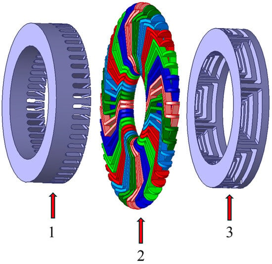
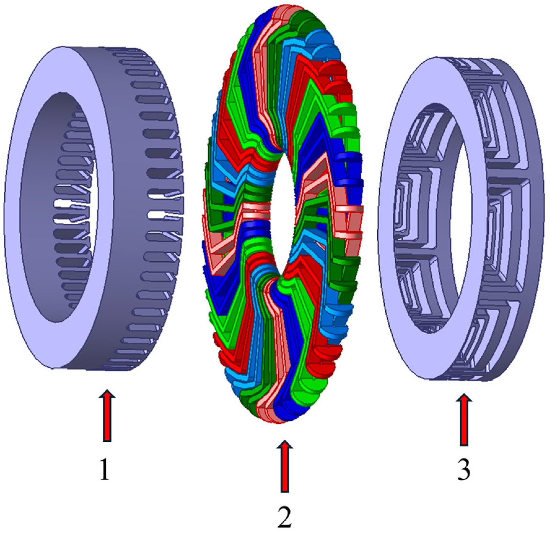
The AF-SynRM topology used in this study is shown in Figure 1. The motor structure was designed using a single stator–single rotor (single-sided) AF configuration. In this topology, the magnetic flux completes its path in the axial direction, contributing to the achievement of a compact structure and high torque density. Flux barriers enabling reluctance torque production were employed in the rotor structure, and no rotor winding or permanent magnet was used on the rotor. Owing to this structure, rotor copper losses were eliminated, supporting the high-efficiency characteristic of the motor.
Figure 1.
AF- SynRM (1. stator, 2. winding, and 3. rotor).
In the AF-SynRM configuration shown in Figure 1, the stator windings have a conventional three-phase distributed winding configuration. The rotor structure consists of 8 poles, each containing 4 flux barriers [8]. The rotor geometry is designed to create a distinct reluctance difference between the d and q axes. This reluctance difference forms the fundamental mechanism for electromagnetic torque generation in SynRM motors. The three-dimensional magnetic flux distribution generated in the AF topology contributes to the motor’s high torque density, whilst also making the effects of electromagnetic asymmetries arising under fault conditions more critical. The main technical specifications of the AF-SynRM are summarized in Table 1.
Table 1.
Technical specifications of the AF-SynRM.
2.2. Stator Interturn Fault (SITF) in the AF-SynRM
SITF occurring in electrical machines arises as a result of the weakening of the insulation structure due to thermal, electrical, or mechanical stresses. These faults, which initially appear as minor insulation degradations, cause high circulating currents to flow through the short-circuited turns and can rapidly develop into severe winding damage [26,27].
The SITF condition occurring in the AF-SynRM is illustrated in Figure 2. Under fault conditions, the short-circuited turns form a low-impedance closed current loop, causing the generation of a fault loop current (). This circulating current leads to local temperature rise, additional copper losses, and electromagnetic imbalances. Furthermore, due to the short-circuited turns, the phase impedance changes and the current distribution within the motor becomes asymmetric [19,20].
Figure 2.
SITF occurrence and fault current path in the AF-SynRM.
The electromagnetic asymmetry caused by SITF disrupts the magnetic flux distribution in the air gap, negatively affecting the operating characteristics of the motor. This condition may lead to various problems such as phase current imbalance, torque ripples, increased vibration, efficiency reduction, and deterioration of the power factor [19,20]. Particularly in AF machines, due to the three-dimensional nature of the magnetic flux, the effects of such electromagnetic disturbances on motor performance are considered to become more pronounced.
In this study, in order to create different fault levels, specific points of the stator windings were brought outside the motor, and controlled SITF scenarios were established using different fault resistances (). The fault level was expressed by the parameter, which is defined as the ratio of the number of short-circuited turns to the total number of turns.
2.3. Mathematical Modeling of SITF in the AF-SynRM
In order to analyze the electromagnetic behavior of the AF-SynRM under SITF conditions, the voltage equations of the motor in the abc reference frame were established. Under fault conditions, the phase voltages and current distributions become asymmetric due to the short-circuited turns. Therefore, the fault loop current () and parameters were included in the model [22,27].
The voltage equations of the AF-SynRM in the abc reference frame under SITF conditions are expressed as follows:
Here, , represent the phase voltages, the inter-winding fault voltage, the stator winding resistance, , , , the phase currents, the fault current, and the fault resistance; represents the mutual inductance between the stator windings, represents the total number of windings and represents the number of short-circuited windings, a, b and c are the self-inductances of the a, b and c phases, is the leakage inductance, and is the average value of the self-inductance; is the amplitude of the sinusoidal fluctuation around this average value, and the fault ratio is defined as follows.
In order to analyze the dynamic behavior of the motor more effectively, the equations in the abc reference frame were transformed into the reference frame using the Park transformation. The voltage equations of the AF-SynRM -axis model under SITF conditions are given below:
Here, and represent the d-q axis currents, and represents the rotating magnetic field speed, while and represent the fault voltages in the dq-axis. The inductances in the d-q axes, and are calculated using Equation (9) and Equation (10), respectively. The electromagnetic asymmetry caused by SITF leads to variations in the dq-axis inductances and directly affects the current distribution of the motor.
Through this mathematical model, the effects of SITF on phase currents, fault current, electromagnetic torque production, power factor, efficiency, and MTPA angle behavior can be analyzed.
2.4. Electromagnetic Torque, MTPA Angle, and Power Factor Expressions
Certain performance parameters can be calculated from the three-phase current and voltage input data of electrical machines. The values , , and are obtained using Park-Clarke transformations. In SynRMs, electromagnetic torque production occurs due to the reluctance difference between the - and -axes. The magnetic asymmetry occurring under SITF conditions affects this reluctance difference, leading to changes in the torque production characteristics of the motor [3,28]. The electromagnetic torque equation of the AF-SynRM is expressed as follows:
MTPA angle control is widely used in SynRM drives to achieve maximum torque production per unit current. However, when SITF occur, the symmetry of the phase windings is disrupted, resulting in an asymmetric rotating field. This situation leads to significant electromagnetic imbalances in the flux distribution within the motor’s air gap and non-linear changes in the and axis inductances (), which directly affect the reluctance torque. As a result, the operating point may deviate from the optimum MTPA condition, leading to changes in the current vector trajectory.
To investigate this behavior, the current vector angle was calculated as:
Here, represents the current vector angle in the dq reference frame, calculated from the measured and components. In this study, it is used to evaluate the operating point of the machine and to investigate changes in the MTPA operating trajectory under different fault conditions.
AF-SynRM power factor is calculated from the current and voltage values on the d- and q-axis pairs as follows:
Using the mathematical model and experimental infrastructure established in this study, the performance variations of the AF-SynRM under different fault levels and fault resistance conditions were comprehensively investigated. In particular, by jointly evaluating the variations in phase current, fault current, power factor, and MTPA angle behavior, the effects of SITF on AF-SynRM performance were analyzed multidimensionally.
3. Experimental Setup and Data Acquisition
3.1. Experimental Test Bench
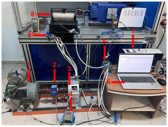
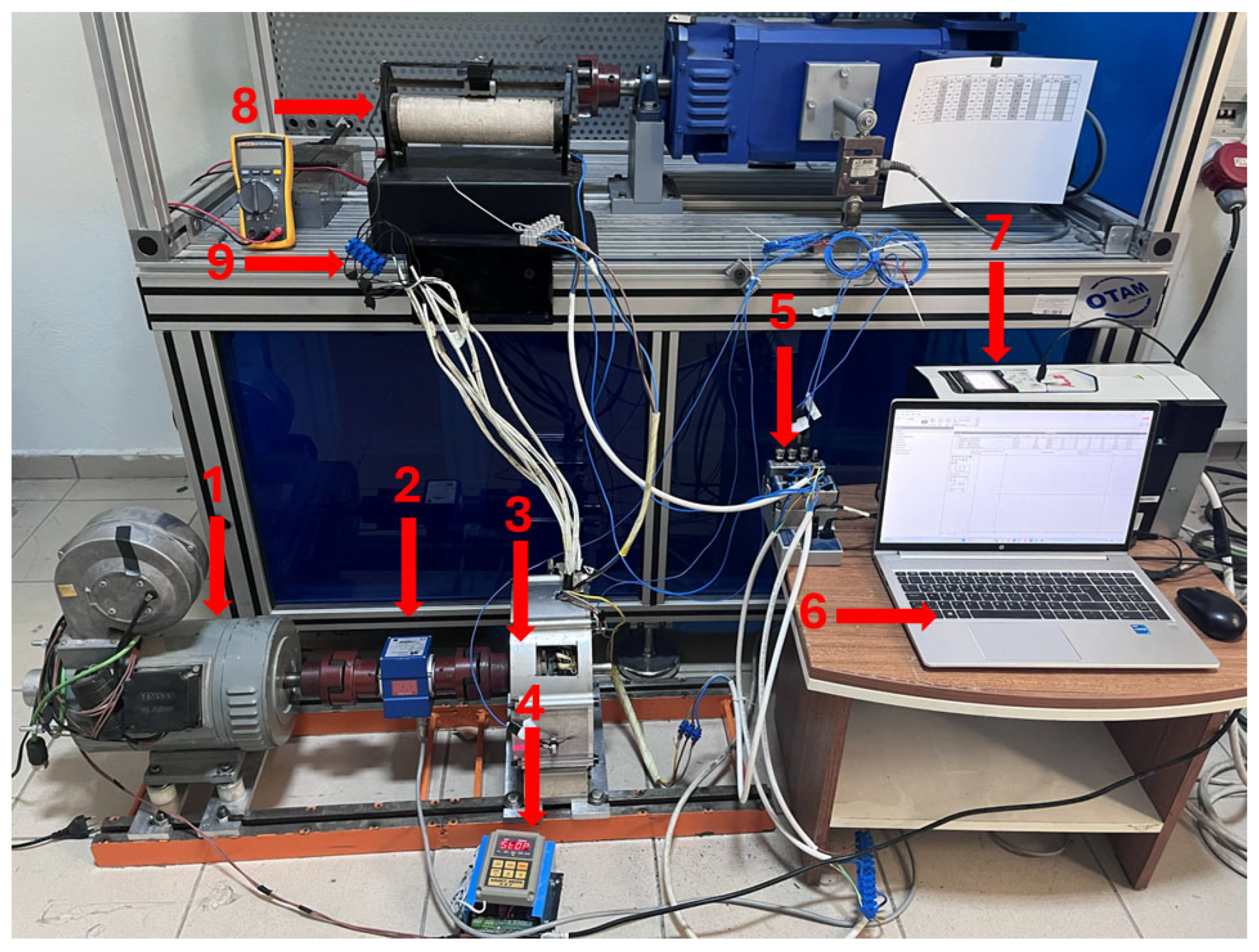
In this study, a comprehensive experimental test setup was established in order to investigate the performance variations of the AF-SynRM under SITF conditions. The experimental system consists of a test motor, load motor, motor drive, data acquisition system, and fault generation infrastructure. The experimental setup is shown in Figure 3.
Figure 3.
AF-SynRM experimental setup (1. Eddy Current Brake, 2. Torque Sensor, 3. Prototype Motor, 4. Eddy Current Brake Drive, 5. Data Acquisition Card, 6. Control Unit, 7. ACS880 Motor Drive, 8. External Resistance, 9. Faulty Winding Connection Point).
The tested AF-SynRM and the load motor were mechanically coupled on the same shaft axis through a coupling mechanism. The system was controlled via the drive and operated under different speed and load conditions. During the experiments, the motor speed information was monitored through the encoder, while the electromagnetic torque values were obtained using the drive outputs and the torque measurement system. Thus, the motor behavior under different operating conditions could be analyzed under steady-state operation.
Within the scope of the experimental study, the motor was tested at four different speed levels (500, 1000, 1500, and 2000 rpm) and five different load conditions (25%, 50%, 75%, 100%, and 115%). The load conditions used throughout the experiments were defined as percentages of the rated motor torque. Based on the rated torque of 2.55 N·m, the applied load levels of 25%, 50%, 75%, 100%, and 115% correspond to approximately 0.64, 1.28, 1.91, 2.55, and 2.93 N·m, respectively. Thanks to this experimental structure covering a wide operating region, the performance variations of the AF-SynRM under different fault conditions could be investigated in detail.
An eddy current brake was used as the loading element in the experimental setup. The eddy current brake produces load torque proportional to the DC excitation voltage applied to the pole windings. The system operates within a 0–48 V DC excitation voltage range and can generate a maximum torque of 20 Nm within this range. The maximum operating speed of the eddy current brake is 4000 rpm, and it is designed for continuous duty operation (S1). In addition, the system operates with a 48 V DC excitation voltage and a 2.2 A DC excitation current. Owing to these characteristics, the motor could be tested stably under different load conditions throughout the experiments.
All experiments were performed using an ACS880 drive operating in Direct Torque Control (DTC) mode. Thanks to its rapid torque and flux regulation capability, the DTC algorithm can partially compensate for distortions caused by inter-winding short-circuit faults by continuously adjusting the current vector. Therefore, some fault-related symptoms may appear less pronounced, especially under low-severity fault conditions. However, the experimental results show the effects of SITF through changes in fault current, phase current behavior, power factor, and MTPA characteristics as fault severity increases. Consequently, the potential impact of the control strategy was considered when interpreting the experimental findings.
A rotary-type torque sensor was used in the experimental setup to measure the mechanical quantities obtained from the motor shaft. The sensor has a maximum torque measurement capacity of 20 Nm and produces a 5 V analog signal at full-scale output. In addition, it was configured to provide a 5 V output at 5000 rpm for speed measurement and supports a maximum operating speed of 20,000 rpm. Thanks to its low-inertia structure, the measurement system enables precise torque measurements under dynamic operating conditions.
To ensure reliable and repeatable measurements, all experiments were carried out under thermally stable operating conditions. Before data acquisition, the motor was operated until its temperature reached a steady state, and measurements were started only after the temperature variation became sufficiently small. During the experiments, the motor temperature was periodically monitored using an infrared thermal camera to verify comparable thermal conditions for both healthy and faulty operating states. Although temperature rise is an important consequence of inter-turn short-circuit faults, the primary objective of this work was to investigate the electrical performance variations caused by SITF. Therefore, a detailed thermal analysis was not included in the scope of the present study and is considered as a topic for future work.
3.2. SITF Generation and Fault Scenarios
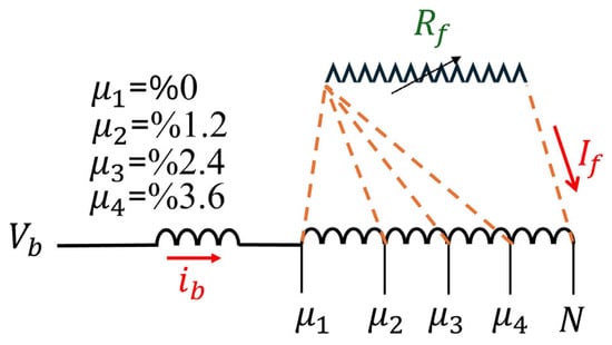
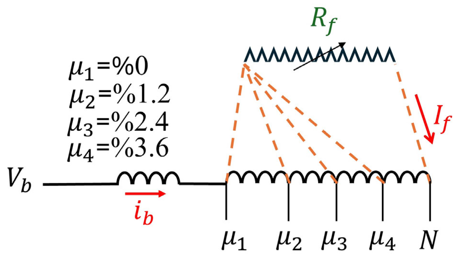
In order to create controlled SITF scenarios in the AF-SynRM, specific connection points of the stator windings were brought outside the motor. Thanks to this structure, controlled fault conditions could be established by connecting different fault resistances across the short-circuited turns. Through the experimental fault infrastructure, different fault levels and fault resistance combinations were applied in a safe and repeatable manner.
The fault level was defined by the parameter μ, which represents the ratio of the number of short-circuited turns (5, 10, 15 turns) to the total number of turns (416 turns). In this context, , , and conditions representing different fault levels were established and expressed as percentages. In addition, three different were used in order to vary the current level in the fault loop. The fault resistance values were determined through preliminary experimental tests carried out on the developed setup. As no standard fault resistance values are available in the literature for AF-SynRM inter-turn fault studies, several resistance levels were initially examined. The values of 4.2 Ω, 7.1 Ω, and 9.2 Ω were selected because they produced clearly distinguishable fault-current responses while ensuring stable operation during the experiments. The generated experimental scenarios and related parameters are presented in Table 2.
Table 2.
Fault severity and fault resistance combinations used in SITF experimental scenarios.
It should be noted that the repeated ) entries in Table 2 were not intended to represent different healthy operating conditions. Instead, they were included to establish a common baseline for each fault resistance scenario and to facilitate a systematic investigation of fault development. In practice, inter-turn faults originate from localized insulation deterioration and evolve progressively as the degradation mechanism advances. Accordingly, each fault resistance scenario was defined starting from the healthy operating condition and extended toward increasing fault severities. This experimental framework allows the effects of fault severity and fault resistance to be evaluated relative to a consistent reference condition [29].
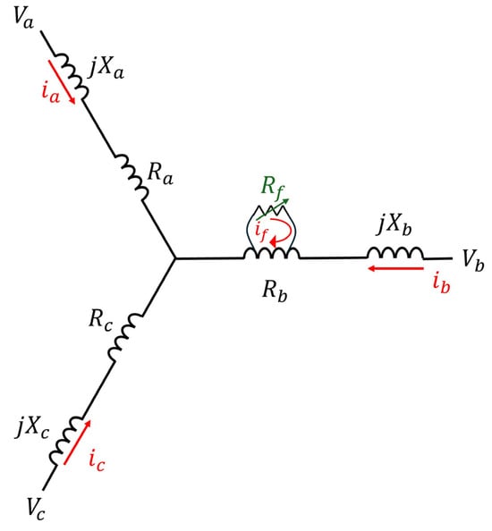
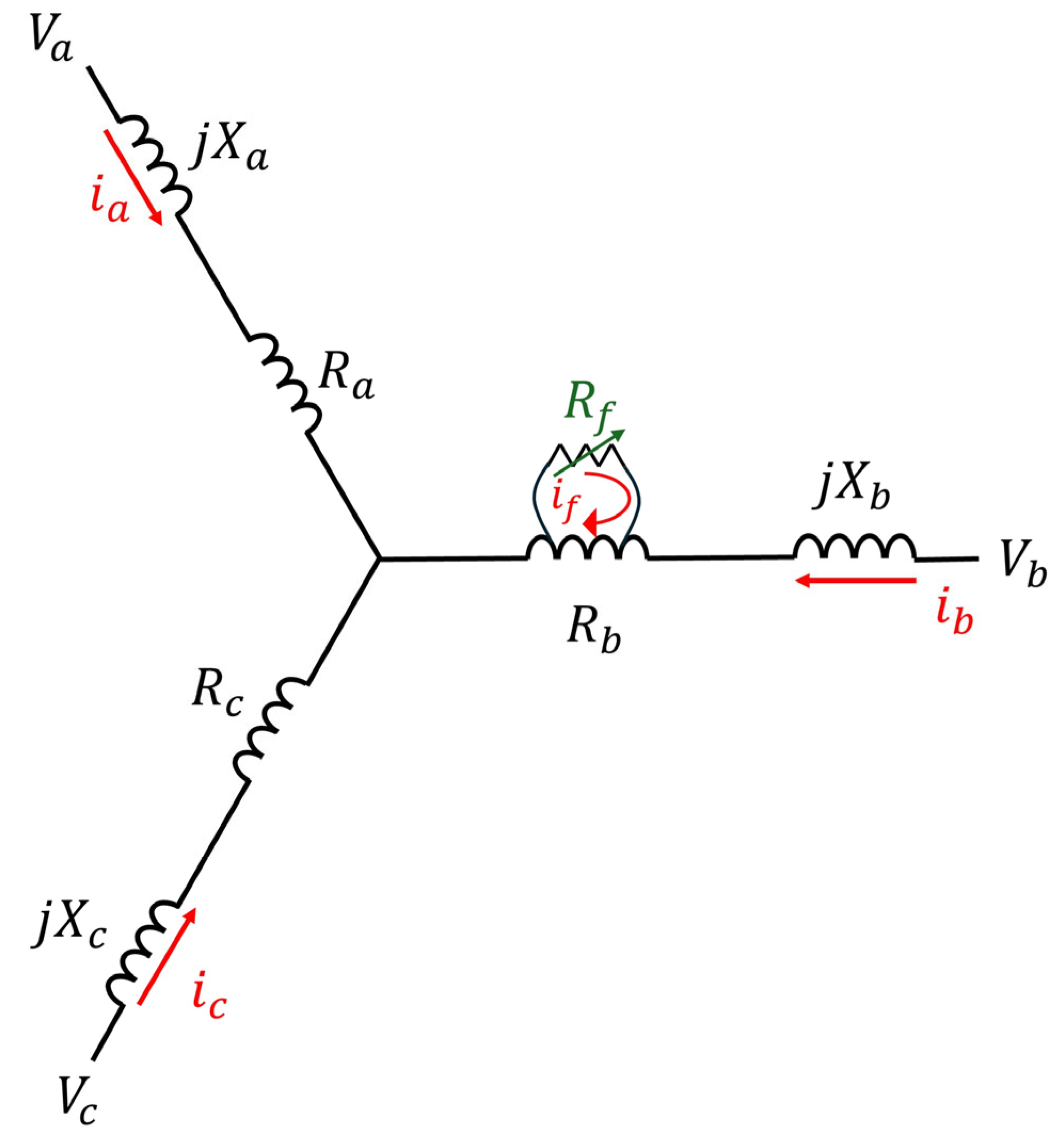
Figure 4 illustrates the equivalent phase winding circuit of the AF-SynRM under SITF conditions. During the fault condition, a circulating fault current () flows through the short-circuited turns and circulates over the fault resistance (). This circulating current causes phase current asymmetry, additional copper losses, and electromagnetic imbalances within the motor. In addition, as the ratio of short-circuited turns increases, the electromagnetic characteristics of the fault loop change, resulting in more noticeable effects on motor performance.
Figure 4.
Equivalent phase winding circuit model of AF-SynRM under SITF conditions.
The experimental scenarios were designed not only to include different fault severities and fault resistances, but also to cover a wide operating region in terms of speed and load conditions. Thus, the effects of SITF on AF-SynRM performance were evaluated multidimensionally over a wide operating range.
3.3. Data Acquisition System
In the experimental studies, a National Instruments-based modular data acquisition system was used in order to measure electrical quantities simultaneously and with high accuracy. The data acquisition infrastructure consists of an NI cDAQ-9174 modular data acquisition chassis and related measurement modules. Thanks to the multi-channel and simultaneous data acquisition capability of the employed system, different electrical signals could be analyzed using the same time reference.
The main hardware components used in the experimental measurement system are presented in Table 3.
Table 3.
Components of the experimental measurement system.
The NI9227 current module was used for current measurements. Through this module, the three-phase currents of the motor (, , ) and the fault current () occurring under fault conditions were directly measured. Thus, the current asymmetries caused by SITF could be analyzed with high accuracy. The NI9225 voltage module was used for voltage measurements. Analog torque and speed data acquired from the driver were recorded using the NI 9239 module.
The employed data acquisition modules have 24-bit resolution and hardware-based anti-aliasing filter features. In addition, since simultaneous data acquisition from all channels was possible, phase relationships and fault-induced electrical variations could be investigated with high precision.
3.4. Experimental Data Acquisition Procedure
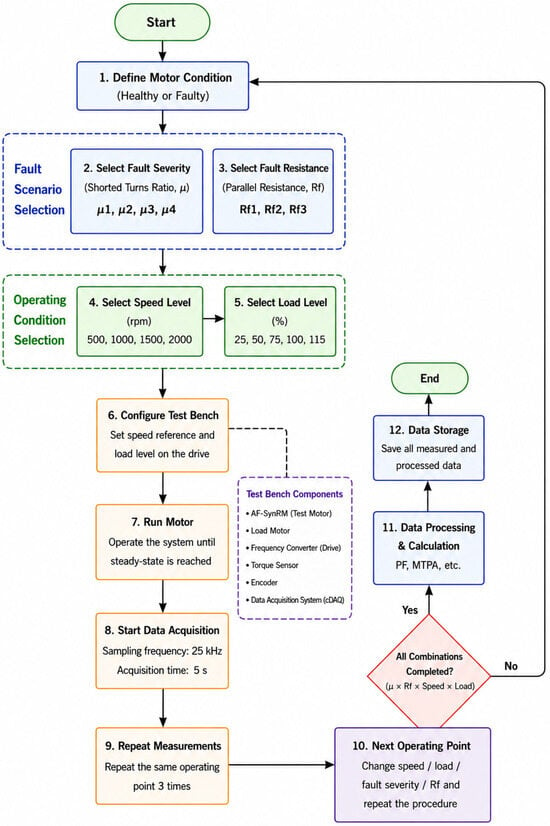
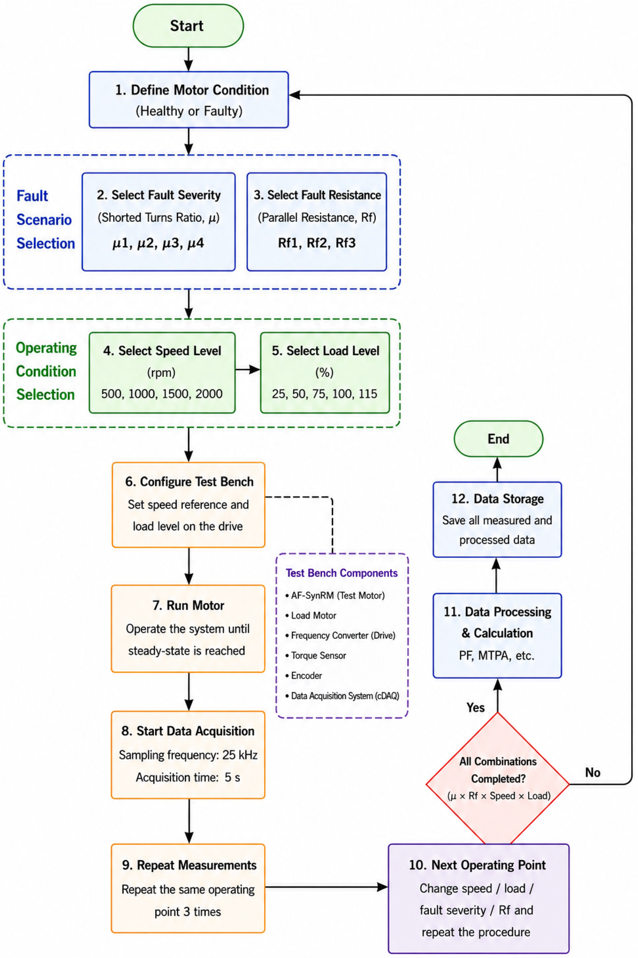
The experimental data acquisition procedures were carried out under a systematic procedure. First, the operating condition of the motor (healthy or faulty) was determined, followed by the selection of the fault level and fault resistance. Then, the motor was operated at the specified speed level, and the corresponding load ratio was applied through the load motor.
After the system reached steady-state operating conditions, the data acquisition process was initiated. All measurements were performed with a sampling frequency of 25 kHz, and a 5 s data recording was obtained for each operating point. The selected sampling frequency was preferred in order to analyze fault-induced electrical variations with sufficient temporal resolution.
To improve the reliability of the experimental measurements, each operating point was repeated three times, and the average values of the obtained data were used. In this way, measurement consistency and experimental repeatability were ensured.
The experimental dataset generated within the scope of this study covers a wide operating region including different combinations of speed, load, fault level, and fault resistance. Thanks to this structure, the performance variations of the AF-SynRM under SITF conditions could be analyzed multidimensionally. Figure 5 shows the flowchart of the experimental data collection setup.
Figure 5.
Experimental Data Acquisition and Signal Processing Flowchart.
3.5. Data Processing and Signal Analysis
Data acquisition and preprocessing processes were carried out using specialized software developed within the LabVIEW 2011 (National Instruments) environment. Through the developed software, all signals obtained during the experiments were synchronously recorded and stored in a suitable format for analysis.
Using the collected experimental data, phase current, fault current, power factor, and MTPA angle parameters were calculated. In addition, performance maps showing the performance variations of the AF-SynRM were generated using the data obtained under different operating conditions.
Thanks to this comprehensive experimental infrastructure, the electrical performance variations of the AF-SynRM under SITF conditions were investigated with high accuracy, and the effects of different fault scenarios on motor behavior were analyzed in detail.
4. Result and Discussion
In this section, the effects of SITF created in the AF-SynRM on the electrical performance and control characteristics of the motor were experimentally investigated. Within the scope of the analyses, phase current (), fault current , power factor (), and maximum torque per ampere (MTPA) angle behavior were evaluated under different speed, load, fault level, and fault resistance conditions. Thus, not only the effects of SITF on current magnitudes but also its effects on the energy conversion performance and control behavior of the motor were comprehensively revealed.
4.1. Effect of SITF Severity on Faulty Phase Current ()
The faulty phase current () is one of the most critical indicators for evaluating the electromagnetic effects of SITF on the motor. The low-impedance current path formed by the short-circuited turns causes significant imbalances in the phase current distribution and increases current stress, particularly under high-load conditions.
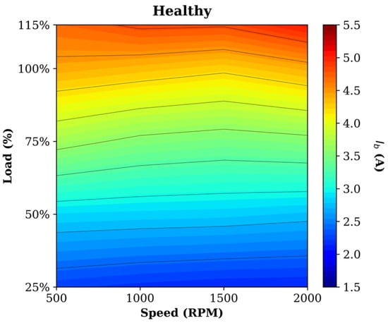
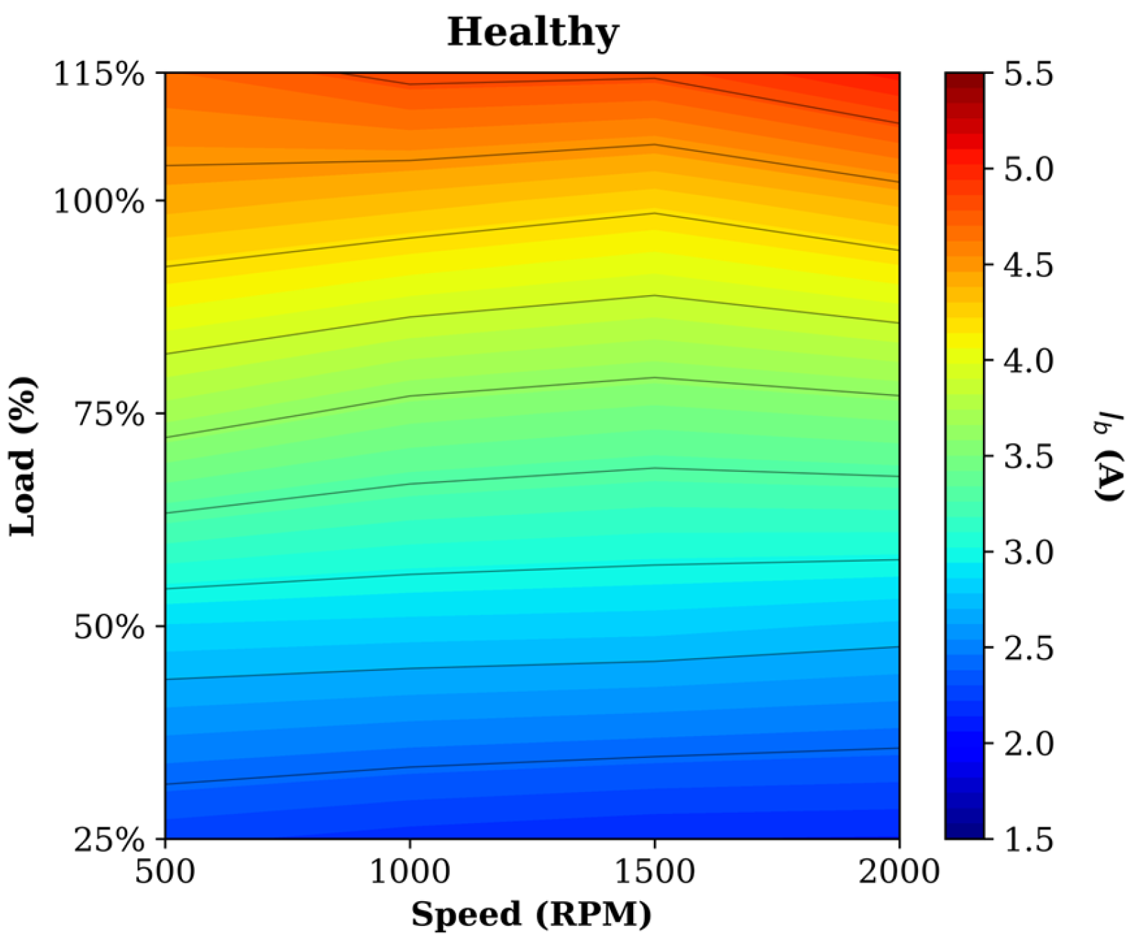
Figure 6 presents the current distribution of the AF-SynRM under healthy operating conditions. Under healthy conditions, it is observed that the current increases regularly with increasing speed and load. In particular, the current value becomes higher in high-load regions. However, under healthy operating conditions, the current distribution exhibits a highly stable and symmetrical characteristic.
Figure 6.
Speed–load distribution of the current under healthy operating conditions.
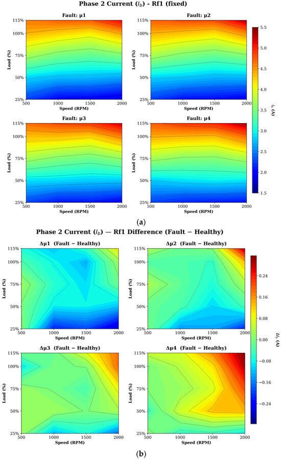
Figure 7a presents the current distributions for different fault severities under constant fault resistance conditions. As the fault severity increases, the phase current gradually rises, with the most pronounced changes occurring in the high-speed and high-load operating regions. In particular, the condition exhibits a noticeable expansion of the high-current zones across the operating map. This behavior can be attributed to the increased electromagnetic asymmetry and the reduction in the effective phase impedance caused by the growing number of short-circuited turns.
Figure 7.
Phase current characteristics under constant conditions (a). absolute current distributions for different SITF levels (b). Phase current deviation relative to the healthy condition for different SITF levels.
To provide a clearer view of the fault-induced current variation, Figure 7b presents the current deviation relative to the healthy operating condition, calculated using Equation (14). Unlike the absolute current distributions shown in Figure 7a, this representation directly highlights the regions where the fault alters the phase current. The results indicate that the magnitude and spatial extent of the current deviation increase with fault severity. Consistent with the observations in Figure 7a, the case exhibits the largest positive current deviations over a broad operating region, confirming the stronger influence of severe inter-turn faults on the electrical behavior of the machine.
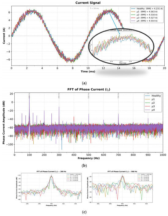
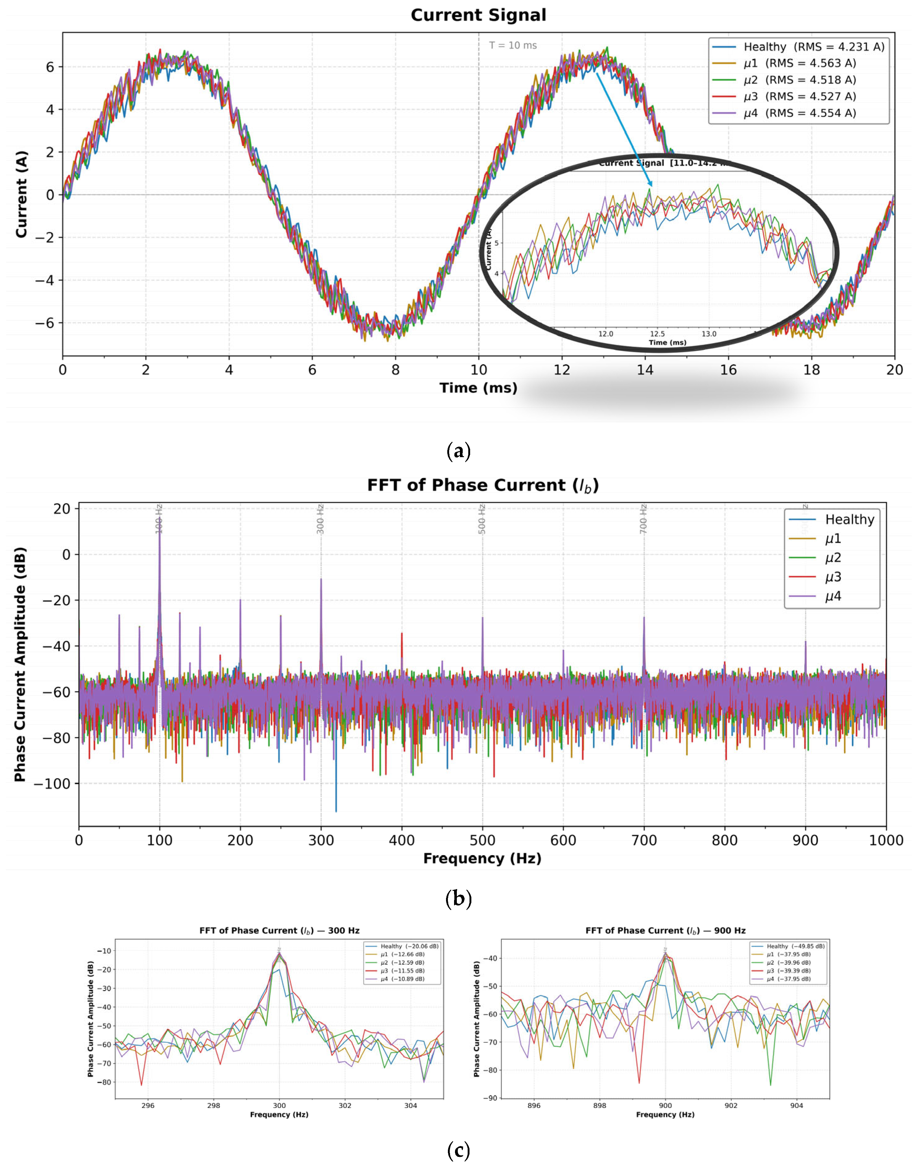
Figure 8 presents a comparative analysis of the phase-current characteristics obtained under healthy and different fault-severity conditions at 1500 rpm and 100% load. As shown in Figure 8a, the phase-current waveform generally preserves its sinusoidal nature under all operating conditions. However, fault conditions introduce noticeable changes in both waveform shape and current magnitude. The enlarged view reveals that the faulty cases exhibit a more irregular current profile compared to the healthy condition, indicating the influence of the circulating current generated within the short-circuited turns. In addition, the RMS current increases from approximately 4.23 A in the healthy condition to about 4.52–4.56 A under fault conditions.
Figure 8.
Comparison of phase-current characteristics under healthy and different fault-severity conditions at 1500 rpm and 100% load. (a) Time-domain current waveforms and corresponding RMS values. (b) FFT spectra of the same signals presented in dB scale. (c) Enlarged views of selected harmonic components (300 Hz and 900 Hz) highlighting the fault-induced spectral variations.
To further investigate these variations, Figure 8b presents the corresponding FFT spectra of the phase-current signals. In order to improve the visibility of fault-related spectral changes, the FFT amplitudes are presented in dB scale. Although the fundamental component remains dominant, noticeable differences can be observed in several harmonic components under fault conditions. For a more detailed comparison, enlarged views of the 300 Hz and 900 Hz harmonic components are presented in Figure 8c. These frequencies correspond to the 3rd and 9th harmonics of the fundamental component and were selected for detailed investigation because previous studies have shown that these harmonic components are particularly sensitive to the presence of stator inter-turn faults in synchronous reluctance motor drives [27]. Therefore, they were selected for detailed investigation in the present study. The results show that the amplitudes of these harmonics increase under fault conditions compared with the healthy case, and the differences become more distinguishable in the dB representation. These findings indicate that SITF affects not only the time-domain behavior of the phase current but also its frequency-domain characteristics, providing additional information about the electrical response of the machine under different fault severities.
The general trends observed in Figure 7 are more clearly supported by the representative experimental results presented in Table 4 for different speed and load conditions. When the table is examined, it is observed that the increase in the faulty phase current becomes more pronounced, especially under high-load conditions. For example, under the 2000 rpm and 115% load condition, the current, which is approximately 5.06 A in the healthy condition, reaches up to 5.35 A in some SITF scenarios. This result indicates that the motor windings are subjected to higher current stress, particularly under high electromagnetic loading conditions.
Table 4.
Representative
current values and percentage variations under different SITF conditions.
On the other hand, the results also reveal that the variation in the current does not depend solely on the fault level. At some operating points, medium-level faults were observed to produce higher current values. The main reason for this is that the variation in the number of short-circuited turns affects not only the current magnitude but also the impedance of the fault loop and the magnetic coupling structure. Therefore, it can be stated that the SITF effect in the AF-SynRM is shaped by the electromagnetic interaction jointly determined by fault level, fault resistance, and operating conditions.
These results indicate that SITF significantly increases the electromagnetic and thermal stress of the motor, particularly in high-speed and high-load regions. The increases in phase current not only raise the copper losses but also increase the inverter current stress, thereby negatively affecting the operational reliability of the motor drive system.
4.2. Effect of SITF on Fault Current Characteristics ()
In interturn short-circuit faults, the fault loop current is one of the most important parameters directly representing the physical effect of the fault. Under healthy operating conditions, no current is generated since there is no short-circuit loop. Therefore, the variation of the current under different fault levels, fault resistances, speed, and load conditions is of critical importance for evaluating the electromagnetic effects of SITF.
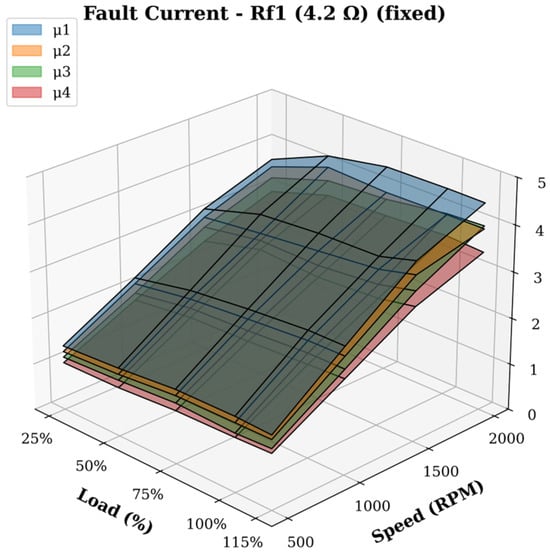
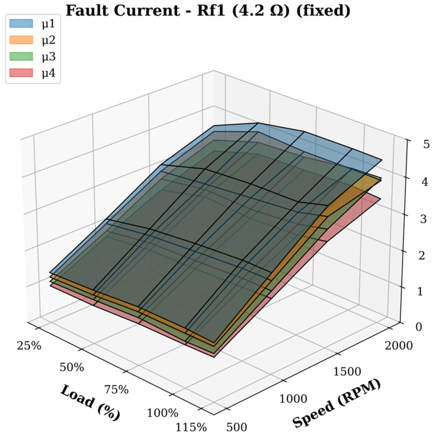
Figure 9 presents the variation of the current in the speed–load plane for different short-circuited turn ratios under constant conditions. When the graph is examined, it is observed that the current is more sensitive to motor speed than to load variation. In particular, as the speed increases from 500 rpm to 2000 rpm, the induced voltage in the fault loop increases, and accordingly the current rises significantly. This result indicates that the fault loop behaves as magnetically coupled with the air-gap flux rather than directly with the main winding currents, and that speed is one of the main determining parameters in the SITF mechanism.
Figure 9.
Variation of the current in the speed–load plane for different SITF levels under constant conditions.
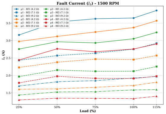
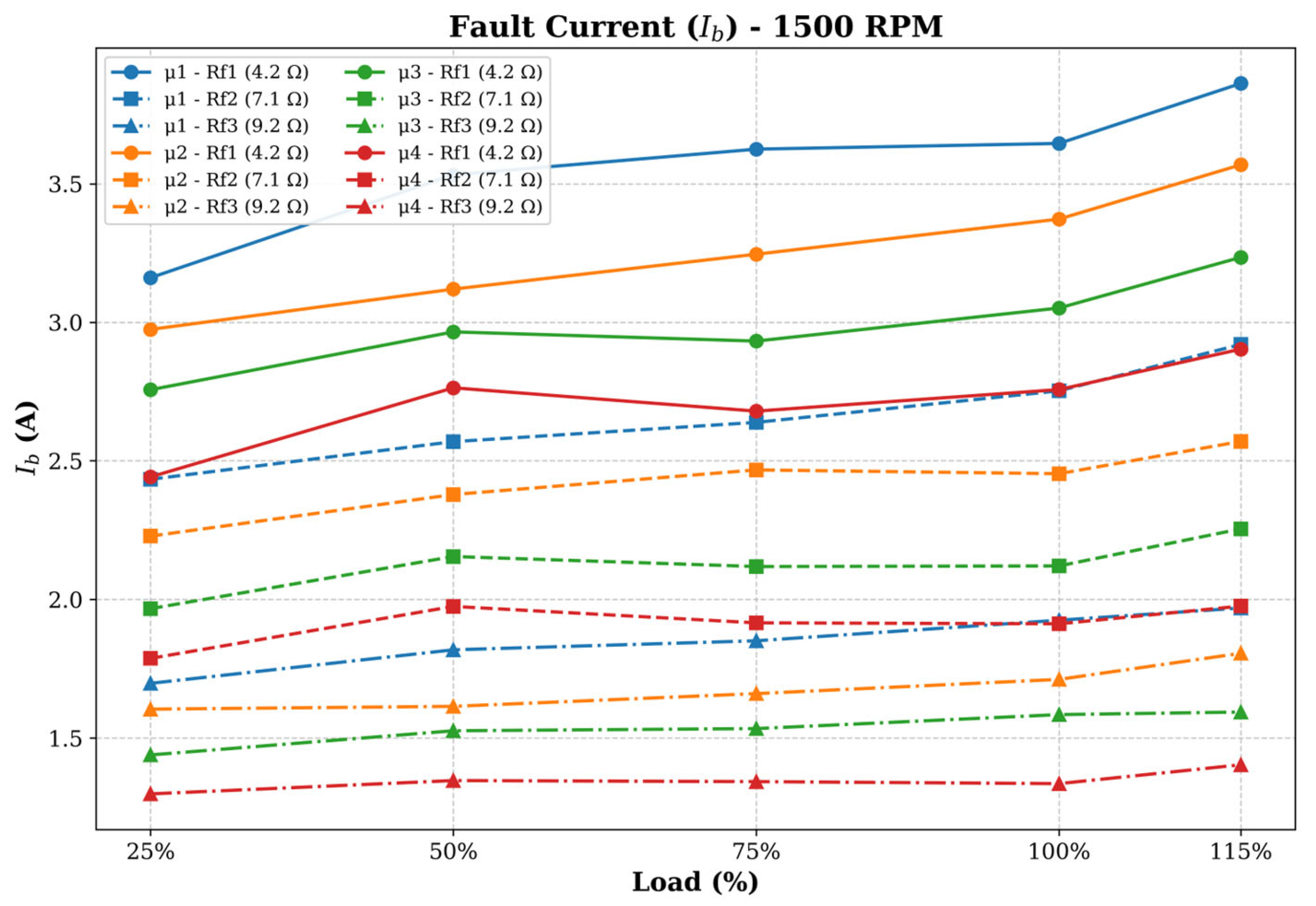
Figure 10 presents the variation of the current with load at a constant speed of 1500 rpm for all fault levels and fault resistances. This graph clearly demonstrates the limiting effect of fault resistance on . Under the low fault resistance condition , the values are at the highest levels for all fault conditions, whereas the current levels decrease significantly under and conditions. This result indicates that fault resistance is the main parameter limiting the circulating current in the short-circuit loop.
Figure 10.
Variation of the current with load at 1500 rpm for different SITF levels and fault resistances.
The experimental results presented in Table 5 quantitatively support this trend. For example, under the 1500 rpm and 115% load condition, the value is 3.8627 A for (-), whereas under the same conditions this value decreases to 1.9692 A for (-). Similarly, under the 2000 rpm and 115% load condition, the if value reaches 4.4653 A for (-), while it remains at 2.2843 A for (-). These results indicate that the increase in fault resistance significantly limits the current in the short-circuit loop.
Table 5.
current values under different speed, load, fault level, and fault resistance conditions.
The results presented in Table 5 further confirm the significant influence of fault resistance on the fault current. For all investigated operating conditions, the highest values were generally observed under the condition, while the current levels decreased as the fault resistance increased to and . This behavior indicates that fault resistance plays a major role in limiting the circulating current within the short-circuit loop. In addition, the results show that the fault-current behavior is affected not only by fault severity but also by operating speed and load conditions. Therefore, the evaluation of should be based on the combined influence of fault severity, fault resistance, speed, and load rather than on a single parameter alone.
These results demonstrate that the fault current provides valuable information about the electromagnetic behavior of the machine under SITF conditions. In particular, the significant increase in observed under low fault resistance and high-speed operating conditions indicates higher current stress within the fault loop and a greater risk of localized thermal effects. It should be noted, however, that is an internal fault quantity circulating within the short-circuited turns and is not directly accessible in practical machine applications. Therefore, in the present study, the fault current is mainly used to investigate the underlying fault mechanism and to support the interpretation of the experimental results.
4.3. Effect of SITF on Power Factor Characteristics
The power factor is one of the important indicators for evaluating the electrical performance variation of the AF-SynRM under fault conditions. Under SITF conditions, the short-circuited turns create asymmetry in the phase currents and alter the magnetic field distribution of the motor. This situation may lead to an increase in current components that do not contribute to active power production and to a rise in the reactive power demand of the motor.
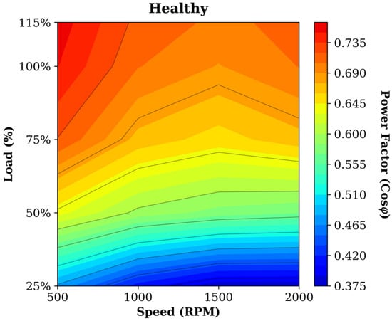
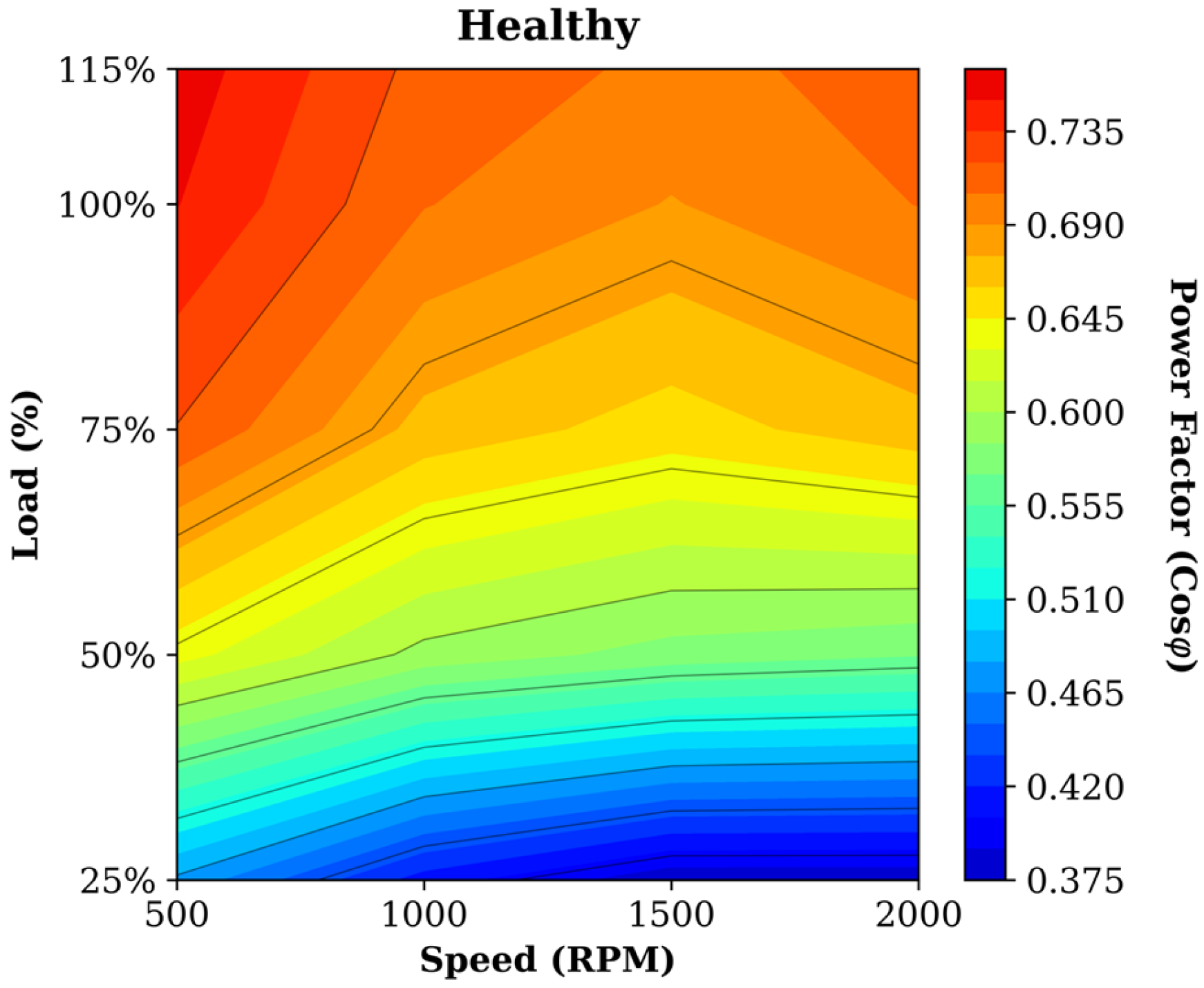
Figure 11 presents the power factor map under healthy operating conditions. Under healthy conditions, it is observed that the power factor increases particularly with increasing load. While the power factor remains at low levels in low-load regions, it reaches higher values in the 100–115% load regions. This behavior is associated with the fact that the SynRM has a relatively higher magnetizing current component at low loads, whereas the active power component becomes more dominant as the load increases.
Figure 11.
Speed–load distribution of the power factor under healthy operating conditions.
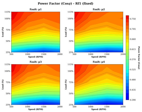
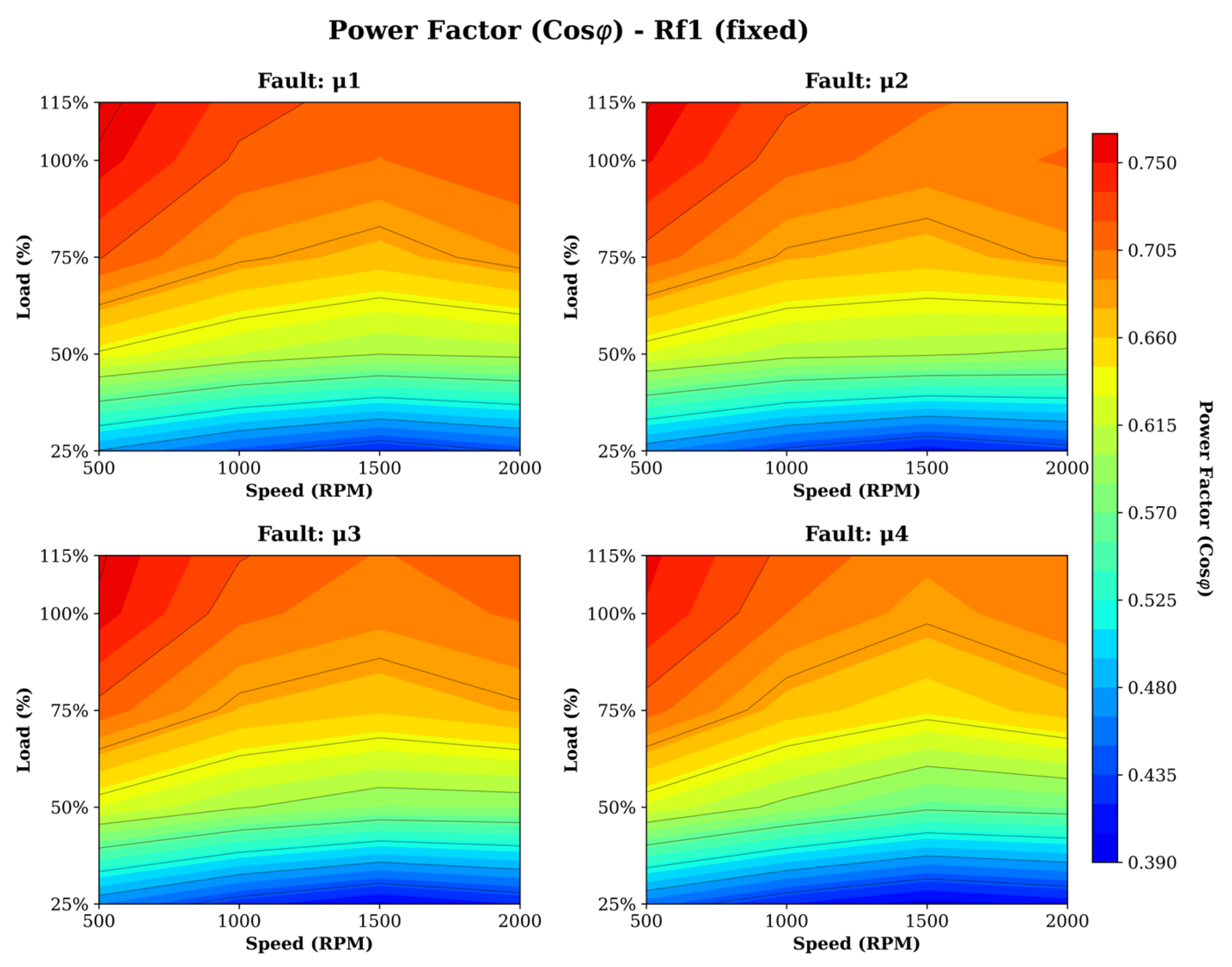
Figure 12 presents the power factor distributions for different SITF levels under constant () conditions. When the fault maps are examined, it is observed that as the fault level increases, the power factor distribution deteriorates compared to the healthy operating condition, especially in medium- and high-load regions. The narrowing of the high power factor region in the and conditions indicates that the increase in the short-circuited turn ratio negatively affects the reactive power balance of the motor.
Figure 12.
Power factor distributions for different SITF levels under constant conditions.
The values presented in Table 6 quantitatively support this trend. For example, under the 500 rpm and 115% load condition, the power factor is 0.7586 in the healthy condition, whereas it decreases to 0.7486 under the -) condition. Similarly, under the 1500 rpm and 115% load condition, the power factor, which is 0.7014 in the healthy condition, decreases to 0.6975 under the -) condition. Although these decreases appear limited, the spread of the fault effect over a wide operating region is important in terms of the motor’s energy quality.
Table 6.
Power factor values under different speed, load, fault level, and fault resistance conditions.
4.4. Effect of SITF on MTPA Angle Characteristics
The MTPA angle is a critical parameter for evaluating the control performance of SynRM-based drive systems, since it represents the maximum torque production per unit current. Under SITF conditions, the short-circuited turns alter the phase current distribution and the magnetic balance in the axes, causing deviations in the optimum current angle. Therefore, the MTPA angle variation indicates not only fault-induced performance degradation but also the deviation of the control strategy from its ideal operating point.
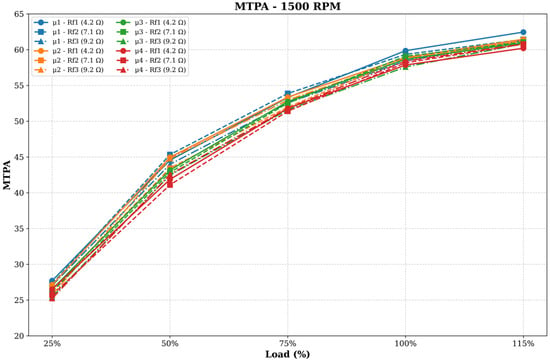
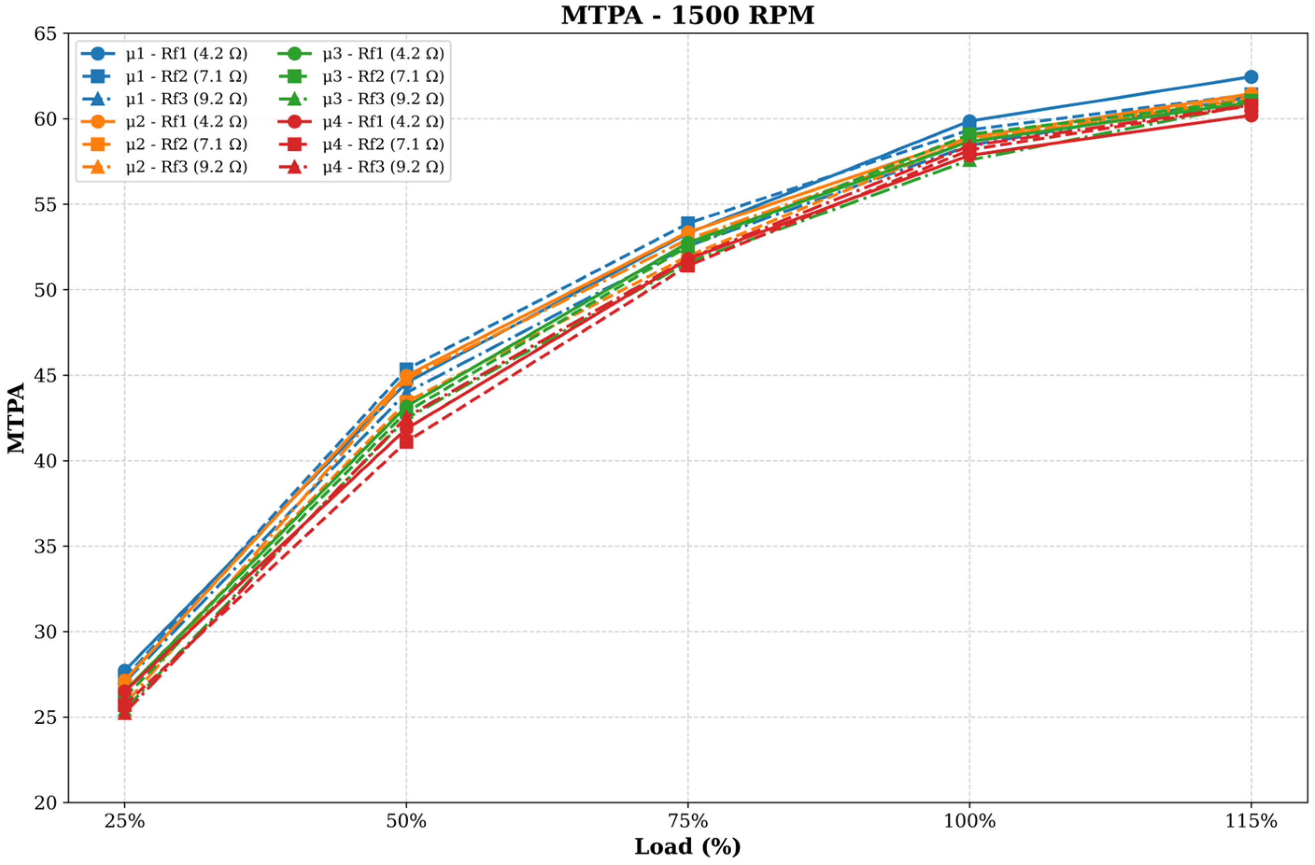
Figure 13 presents the variation of the MTPA angle with load at a constant speed of 1500 rpm for different fault levels and fault resistances. When the graph is examined, it is observed that the MTPA angle increases significantly with increasing load under all conditions. This behavior is associated with the repositioning of the current vector to support reluctance torque production for higher torque generation as the load increases. In particular, the increase in the MTPA angle is more pronounced in the region from 25% load to 75% load, whereas the convergence of the curves in the 100–115% load range indicates that the motor operates within a narrower control region under high-load conditions.
Figure 13.
Variation of the MTPA angle with load at a constant speed of 1500 rpm for different SITF levels and fault resistances.
The experimental results presented in Table 7 quantitatively support the effect of SITF on the MTPA angle characteristic. For example, under the 1500 rpm and 115% load condition, the MTPA angle is approximately 60.49° in the healthy condition, while it reaches 62.46° under the (-) condition and 60.84° under the (-) condition. Similarly, under the 2000 rpm and 115% load condition, the MTPA angle, which is 66.91° in the healthy condition, was obtained as 69.83° for (-) and 66.36° for (-). These results indicate that SITF produces a significant but nonlinear variation in the MTPA angle.
Table 7.
MTPA angle values under different speed, load, fault level, and fault resistance conditions.
As a remarkable finding, it was observed that the variation in the MTPA angle does not progress linearly only with the increase in fault level. At some operating points, low- or medium-level fault conditions produced higher MTPA angle deviations, indicating that the effect of the short-circuited turn ratio on the axis magnetic characteristics varies together with fault resistance and load conditions. This result reveals that SITF has a complex influence not only on current amplitudes but also on the optimum torque production angle of the motor.
Overall, the MTPA angle analysis represents one of the most important control-oriented outcomes of this study. While phase current, fault current, and power factor analyses reveal the electrical effects of the fault, the MTPA angle variation demonstrates the direct impact of the fault on the torque production strategy. Therefore, deviations in the MTPA angle can be considered an important indicator for monitoring SITF-induced control performance degradation in AF-SynRMs and for developing fault-tolerant control algorithms.
5. Conclusions
In this study, the effects of SITF on the electrical performance and control characteristics of the AF-SynRM were experimentally investigated. In this context, comprehensive experimental analyses were carried out under different fault levels (, , , ), fault resistances (, , ), speed levels (500–2000 rpm), and load conditions (25–115%). The effects of SITF on motor performance were multidimensionally evaluated through the analysis of phase current (), fault current (), power factor, and MTPA angle behavior.
The obtained results showed that SITF produces significant effects particularly on phase current and fault current. As the fault level increased, a general increase tendency in phase currents was observed, especially under low fault resistance and high load conditions where electromagnetic current stresses became considerably more pronounced. However, the results also revealed that the current variations did not exhibit a completely linear characteristic. In some operating points, medium-level fault conditions generated higher current values, indicating that the SITF effect depends not only on the short-circuited turn ratio but also on the combined influence of fault resistance, operating point, and magnetic coupling characteristics.
Fault current analyses demonstrated that the circulating current in the short-circuit loop reached significant levels, particularly under low fault resistance conditions. The results revealed that the current is more sensitive to speed and fault resistance than to load variation. Especially in high-speed regions, noticeable increases in levels were observed due to the increase in the induced voltage within the fault loop. This situation indicates that SITF creates critical risks in terms of local thermal stresses and additional copper losses.
Power factor analyses showed that SITF has more limited but measurable effects on the energy conversion performance of the motor. In the power factor maps, it was observed that the high power factor regions became narrower, especially under medium and high load conditions.
The MTPA angle analyses constituted one of the most important control-oriented outcomes of the study. The results showed that SITF affects not only the current magnitudes but also the optimum torque production angle. In particular, the deviations observed in the MTPA angle under different fault levels and fault resistance conditions demonstrated that SITF directly affects the control strategy of the motor. This finding is considered important for the development of fault-tolerant control algorithms in AF-SynRM drives.
Overall, this study demonstrated that the effects of SITF in AF-SynRMs should not be analyzed through a single parameter alone, but rather through the combined evaluation of current behavior, energy quality, and control characteristics. The obtained experimental results are expected to provide an important experimental foundation for future fault diagnosis methods, predictive maintenance applications, and fault-tolerant drive control strategies.
Author Contributions
Conceptualization, all authors; methodology, all authors; investigation, all authors; writing—original draft preparation, all authors; writing—review and editing, all authors. All authors contributed equally to this work. All authors have read and agreed to the published version of the manuscript.
Funding
This research was funded by Tokat Gaziosmanpaşa University Scientific Research Projects Coordination Unit, project numbers 2025/35 and 2026/103, entitled “Effect of Axial Flux Synchronous Reluctance Motor Winding Fault on Motor Performance”.
Data Availability Statement
The data is contained within this article.
Conflicts of Interest
The authors declare no conflicts of interest.
Nomenclature
| a, b, and c phase voltages | |
| a, b, and c phase currents | |
| interturn fault voltage | |
| stator winding resistance | |
| fault resistance | |
| fault current | |
| mutual inductance | |
| total number of windings | |
| number of short-circuited windings | |
| self-inductances | |
| leakage inductance | |
| average value of the self-inductance | |
| sinusoidal fluctuation around this average value | |
| fault ratio | |
| axis voltage | |
| axis voltage | |
| axis current | |
| axis current | |
| rotating magnetic field speed | |
| axis fault voltage | |
| axis fault voltage | |
| axis fault inductance | |
| axis fault inductance | |
| current vector angle in the dq reference frame | |
| electromagnetic torque | |
| efficiency | |
| angular speed | |
| stator current |
References
- Onwunta, O.E.K.; Kahn, M.T.E. Energy Efficiency and Reliability Improvement Strategies in Industrial Electric Motor-Driven Systems (EMDS). In Proceedings of the 2011 8th Conference on the Industrial and Commercial Use of Energy, Cape Town, South Africa, 16–17 August 2011; pp. 100–104. [Google Scholar]
- Saidur, R. A Review on Electrical Motors Energy Use and Energy Savings. Renew. Sustain. Energy Rev. 2010, 14, 877–898. [Google Scholar] [CrossRef] [Scilit]
- Heidari, H.; Rassõlkin, A.; Kallaste, A.; Vaimann, T.; Andriushchenko, E.; Belahcen, A.; Lukichev, D.V. A Review of Synchronous Reluctance Motor-Drive Advancements. Sustainability 2021, 13, 729. [Google Scholar] [CrossRef] [Scilit]
- Ozcelik, N.G.; Dogru, U.E.; Imeryuz, M.; Ergene, L.T. Synchronous Reluctance Motor vs. Induction Motor at Low-Power Industrial Applications: Design and Comparison. Energies 2019, 12, 2190. [Google Scholar] [CrossRef] [Scilit]
- Donaghy-Spargo, C. Synchronous Reluctance Motor Technology: Industrial Opportunities, Challenges and Future Direction. Eng. Technol. Ref. 2016, 2016, 1–15. [Google Scholar] [CrossRef] [Scilit]
- Hao, Z.; Ma, Y.; Wang, P.; Luo, G.; Chen, Y. A Review of Axial-Flux Permanent-Magnet Motors: Topological Structures, Design, Optimization and Control Techniques. Machines 2022, 10, 1178. [Google Scholar] [CrossRef] [Scilit]
- Patterson, D.J.; Colton, J.L.; Mularcik, B.; Kennedy, B.J.; Camilleri, S.; Rohoza, R. A Comparison of Radial and Axial Flux Structures in Electrical Machines. In Proceedings of the 2009 IEEE International Electric Machines and Drives Conference, Miami, FL, USA, 3–6 May 2009; pp. 1029–1035. [Google Scholar]
- Özsoy, M. Design of a Novel Axial Flux Wound-Rotor Synchronous Motor for Electric Vehicles. J. Electr. Eng. Technol. 2026, 1–13. [Google Scholar] [CrossRef] [Scilit]
- Gercekcioglu, H.S.; Akar, M. Optimal Rotor Design of Novel Axial Flux Synchronous Reluctance Motor and Validation. Int. Trans. Electr. Energy Syst. 2021, 31, e12866. [Google Scholar] [CrossRef] [Scilit]
- Eser, E.; Üstkoyuncu, N. Effects of Permanent Magnets on Different Flux Barriers for the AF-SynRMs. Electr. Power Compon. Syst. 2024, 52, 1936–1945. [Google Scholar] [CrossRef] [Scilit]
- Zhou, Y.; Liu, J.; Meng, F.; Yang, G.; He, Y.; Lau, D.K.B.; Wang, P.; Lee, C.H.T. Design of an Axial-Flux Synchronous Reluctance Machine with 3D-Printed Rotor. In Proceedings of the 2023 IEEE International Electric Machines & Drives Conference (IEMDC), San Francisco, CA, USA, 15–18 May 2023. [Google Scholar] [CrossRef] [Scilit]
- Nandi, S.; Toliyat, H.A.; Li, X. Condition Monitoring and Fault Diagnosis of Electrical Motors—A Review. IEEE Trans. Energy Convers. 2005, 20, 719–729. [Google Scholar] [CrossRef] [Scilit]
- Gultekin, M.A.; Bazzi, A. Review of Fault Detection and Diagnosis Techniques for AC Motor Drives. Energies 2023, 16, 5602. [Google Scholar] [CrossRef] [Scilit]
- Gherghina, I.S.; Bizon, N.; Iana, G.V.; Vasilică, B.V. Recent Advances in Fault Detection and Analysis of Synchronous Motors: A Review. Machines 2025, 13, 815. [Google Scholar] [CrossRef] [Scilit]
- Laadjal, K.; Bento, F.; Henriques, K.; Cardoso, A.J.M.; Sahraoui, M. A Novel Indicator-Based Online Diagnostics Technique of Interturn Short-Circuit Faults in Synchronous Reluctance Machines. IEEE J. Emerg. Sel. Top. Power Electron. 2023, 11, 3492–3501. [Google Scholar] [CrossRef] [Scilit]
- Krishna, M.S.R.; Seshadrinath, J. Modeling Analysis and Tolerant Capability for Stator Winding Interturn Fault in Synchronous Reluctance Motor with Series and Parallel Connected Windings. IEEE Trans. Ind. Electron. 2025, 72, 3136–3147. [Google Scholar] [CrossRef] [Scilit]
- Chen, P.; Xie, Y. Harmonics Analysis of Air-Gap Magnetic Field of Induction Motors With Stator Inter-Turn Fault. IEEE Trans. Magn. 2022, 58, 8202409. [Google Scholar] [CrossRef] [Scilit]
- Navarro-Navarro, A.; Biot-Monterde, V.; Ruiz-Sarrió, J.E.; Antonino-Daviu, J. Detection of Stator Asymmetries in Synchronous Reluctance Motors through the Analysis of the Stator Current. In Proceedings of the 2024 International Conference on Electrical Machines (ICEM), Torino, Italy, 1–4 September 2024; pp. 1–6. [Google Scholar]
- Walch, D.; Geiger, A.; Sültrop, C. Inter-Turn Short Circuit Faults and Mitigation Measures for Dual-Three Phase Machines. In Proceedings of the 2024 International Conference on Electrical Machines (ICEM), Torino, Italy, 1–4 September 2024; pp. 1–7. [Google Scholar]
- Pietrowski, W.; Górny, K. Analysis of Torque Ripples of an Induction Motor Taking into Account a Inter-Turn Short-Circuit in a Stator Winding. Energies 2020, 13, 3626. [Google Scholar] [CrossRef] [Scilit]
- Maraaba, L.; Al-Hamouz, Z.; Abido, M. An Efficient Stator Inter-Turn Fault Diagnosis Tool for Induction Motors. Energies 2018, 11, 653. [Google Scholar] [CrossRef] [Scilit]
- Mahmoudi, A.; Jlassi, I.; Cardoso, A.J.M.; Yahia, K.; Sahraoui, M. Inter-Turn Short-Circuit Faults Diagnosis in Synchronous Reluctance Machines, Using the Luenberger State Observer and Current’s Second-Order Harmonic. IEEE Trans. Ind. Electron. 2022, 69, 8420–8429. [Google Scholar] [CrossRef] [Scilit]
- Henriques, K.; Laadjal, K.; Cardoso, A.J.M. Inter-Turn Short-Circuit Fault Detection in Synchronous Reluctance Machines, Based on Current Analysis. Eng. Proc. 2022, 24, 23. [Google Scholar] [CrossRef] [Scilit]
- Chen, X.; Qin, P.; Chen, Y.; Zhao, J.; Li, W.; Mao, Y.; Zhao, T. Inter-Turn Short Circuit Fault Diagnosis of PMSM. Electronics 2022, 11, 1576. [Google Scholar] [CrossRef] [Scilit]
- Akar, M.; Eker, M.; Özsoy, M.; Gerçekçioğlu, H.S. Efficiency Analysis of Axial Flux SynRM in Variable Speed Applications. Machines 2022, 10, 838. [Google Scholar] [CrossRef] [Scilit]
- Krishna, M.S.R.; Seshadrinath, J. Model Based Stator Interturn Fault Analysis in Synchronous Reluctance Motor Drives. IEEE Trans. Ind. Appl. 2024, 60, 8878–8887. [Google Scholar] [CrossRef] [Scilit]
- Rama Krishna, M.S.; Seshadrinath, J. Stator Interturn Fault Modeling and Diagnosis for Synchronous Reluctance Motor Drive. In Proceedings of the 2022 IEEE International Conference on Power Electronics, Drives and Energy Systems (PEDES), Jaipur, India, 14–17 December 2022; pp. 1–6. [Google Scholar]
- Lee, J.-K.; Jung, D.-H.; Lim, J.; Lee, K.-D.; Lee, J. A Study on the Synchronous Reluctance Motor Design for High Torque by Using RSM. IEEE Trans. Magn. 2018, 54, 8103005. [Google Scholar] [CrossRef] [Scilit]
- Zhang, H.; Zhang, M.; Wang, X. Fracture Failure Analysis of Insulation with Initial Crack Defect for Stator End-Winding in Induction Motor by Using Magnetic-Structural Coupling Model. Eng. Fail. Anal. 2023, 149, 107239. [Google Scholar] [CrossRef] [Scilit]


Disclaimer/Publisher’s Note: The statements, opinions and data contained in all publications are solely those of the individual author(s) and contributor(s) and not of MDPI and/or the editor(s). MDPI and/or the editor(s) disclaim responsibility for any injury to people or property resulting from any ideas, methods, instructions or products referred to in the content. |
© 2026 by the authors. Licensee MDPI, Basel, Switzerland. This article is an open access article distributed under the terms and conditions of the Creative Commons Attribution (CC BY) license.