


Abstract
Precision tilt stages capable of high angular resolution and low cross-axis coupling are essential for applications such as free-space optical communication, adaptive optics, and micro/nano-positioning. In this study, a two-degree-of-freedom compliant tilt stage based on differential actuation of positive and negative Poisson’s ratio folded-beam structures is proposed. The stage incorporates four circumferential compliant motion units, each consisting of a W-shaped positive Poisson’s ratio folded beam, an M-shaped negative Poisson’s ratio folded beam, a lever amplification mechanism, and compliant decoupling leaf springs. By exploiting the opposite out-of-plane deformation tendencies of the two folded-beam types under identical input forces, a push–pull differential driving effect is generated, enabling independent tilting motion about two orthogonal axes with enhanced angular output. The lever amplification mechanisms enlarge the small displacement of the piezoelectric actuators, while the decoupling leaf springs suppress parasitic motion and reduce cross-axis coupling. A static analytical model is established based on compliance analysis and force–moment equilibrium. The model predictions are validated through finite element analysis, with errors of 4.77% and 4.80% for the two axes, respectively. Experimental results obtained from a stereolithography-fabricated prototype demonstrate maximum tilt angles of 9.19 mrad and 8.80 mrad about the x- and y-axes under a 150 V driving voltage, while the corresponding coupling angles are only 0.043 mrad and 0.040 mrad, yielding coupling ratios below 0.5%. The proposed design achieves a favorable combination of compact monolithic structure, effective displacement amplification, and excellent decoupling performance, offering a practical solution for precision optical adjustment, beam steering, and micro/nano-positioning systems.
1. Introduction
Precision tilt stages play a critical role in a wide range of high-technology systems, including free-space optical communication, adaptive optics, beam stabilization, precision optical scanning, and micro-attitude adjustment. In free-space optical communication, even small beam pointing errors can significantly reduce the received optical power and degrade link stability [1,2]. In adaptive optics and high-resolution imaging systems, tip/tilt correction directly governs closed-loop accuracy and imaging quality [3,4]. These demanding applications require tilt stages that simultaneously provide high angular resolution, fast dynamic response, compact form factor, and stable motion output [5,6].
Conventional tilt mechanisms based on rigid revolute joints, bearings, or assembled kinematic pairs usually suffer from friction, backlash, wear, assembly errors, and limited repeatability. These limitations are particularly critical in micro-angular positioning applications. Compliant mechanisms transmit motion through elastic deformation, thereby eliminating friction and backlash while offering monolithic fabrication, compactness, and high repeatability [7,8,9]. Owing to these advantages, compliant mechanisms have become an important solution for precision positioning and micro-motion systems.
Piezoelectric actuators are well suited for compliant tilt stages because of their high resolution, fast response, compact size, and easy integration with flexure-based mechanisms [10,11]. Various piezo-actuated pointing mechanisms, laser scanners, and fast steering mirrors have been developed to improve angular output, bandwidth, and structural compactness [12,13]. MEMS tracking mirrors, piezoelectric tilt mirrors, and two-dimensional piezoelectric laser scanners have also demonstrated good potential for compact optical systems [14,15,16]. In addition, high-bandwidth fast steering mirrors and large-aperture MEMS mirrors have been reported for laser beam machining and free-space optical communication applications [17,18,19,20].
For two-degree-of-freedom tilt stages, independent angular outputs about two orthogonal axes must be achieved while suppressing parasitic motion and cross-axis coupling. Existing studies have proposed high-stiffness piezo-driven fast steering mirrors, decoupled miniature fast steering mirrors, fixed-rotation-axis mirrors, and monolithic compliant rotation stages [21,22,23,24]. Other studies have further explored large-stroke multi-DOF steering mirrors, system-integrated fast steering mirrors, dual-mode actuation, and multi-objective optimization methods [25,26,27,28]. Although these works have improved the performance of compliant tilt stages, many designs still require multiple actuators, complex layouts, or additional decoupling units. Achieving large angular output, compact structure, low coupling error, and good dynamic response simultaneously remains challenging.
A key difficulty in compliant tilt stage design is the coupling among driving, guiding, and output motions. Since the desired angular motion is generated by elastic deformation, it is often accompanied by undesired translation, parasitic rotation, or rotational-axis drift [29,30]. To improve motion purity, researchers have proposed input/output decoupling, remote-center-of-motion mechanisms, fully decoupled parallel mechanisms, and compact decoupled micro-positioning stages [31,32,33]. Decoupling strategies have also been extended to multi-DOF compliant stages, including quasi-symmetric XYZ stages, fully decoupled long-stroke parallel stages, six-DOF compliant mechanisms, screw-system-based synthesis methods, and bridge-type displacement amplification structures [34,35,36,37,38]. However, integrating displacement amplification, dual-axis tilt output, and coupling suppression into a compact monolithic tilt stage is still difficult.
To address these issues, this paper proposes a two-degree-of-freedom compliant tilt stage based on differential actuation of positive and negative Poisson’s ratio folded beams. W-shaped positive Poisson’s ratio folded beams and M-shaped negative Poisson’s ratio folded beams are arranged as differential motion units to generate dual-axis tilt output. Lever amplification mechanisms are introduced to enlarge the input displacement of piezoelectric actuators, while compliant decoupling leaf springs are integrated to suppress parasitic motion and reduce cross-axis coupling. The whole stage is designed as a monolithic compliant structure consisting of an outer fixed frame, a central tilt output unit, and circumferential compliant motion units.
The remainder of this paper is organized as follows. Section 2 elaborates on the structural design and working principle of the proposed two-DOF tilt stage. Section 3 establishes the analytical model based on compliance analysis and force–moment equilibrium. Section 4 evaluates the static and dynamic performances of the mechanism via finite element analysis. Section 5 details the experimental setup and comprehensive testing results to verify the proposed design. Finally, Section 6 summarizes the main conclusions.
2. Structural Design and Working Principle
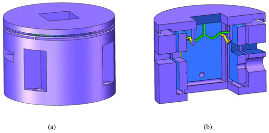
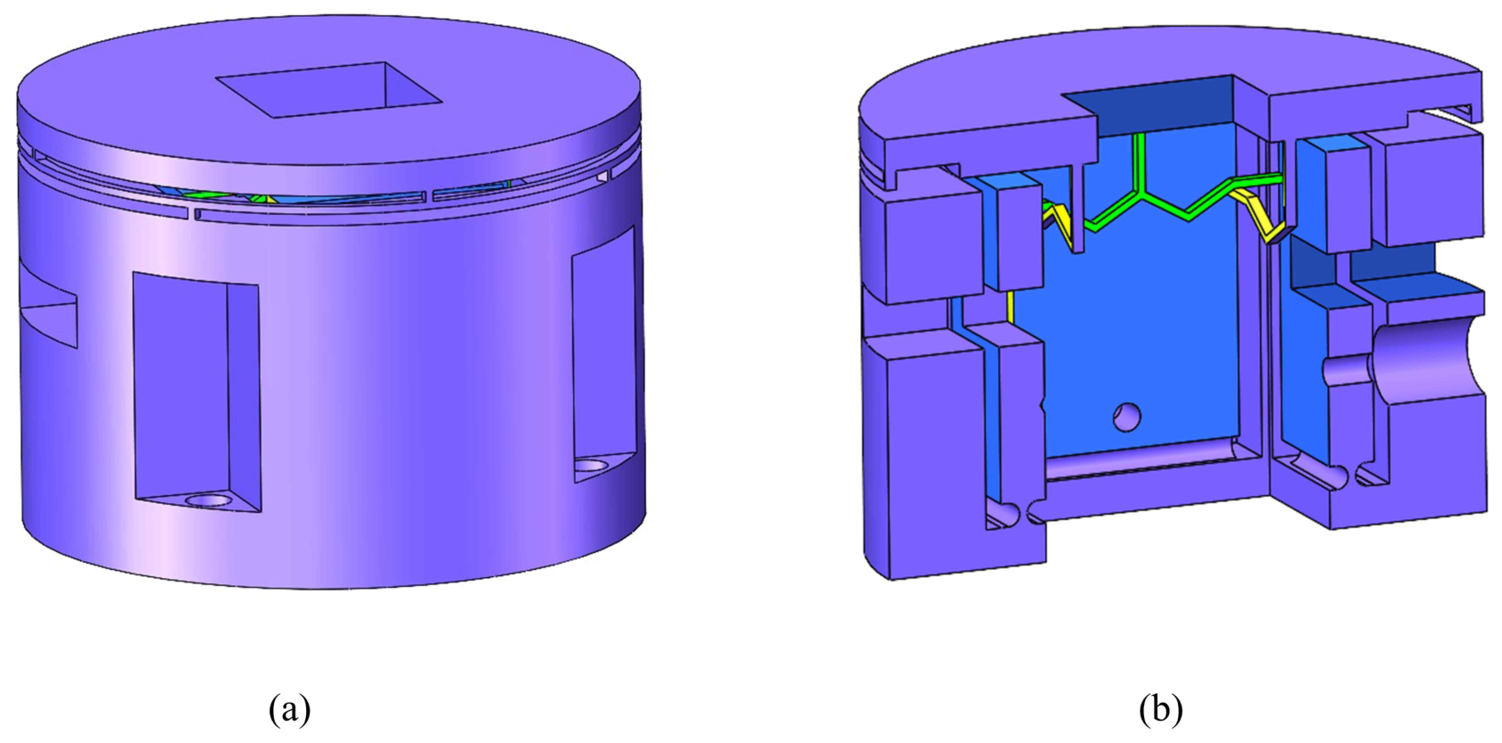
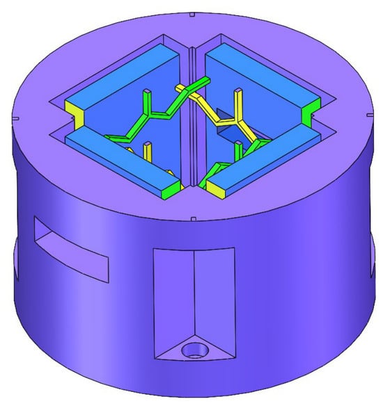
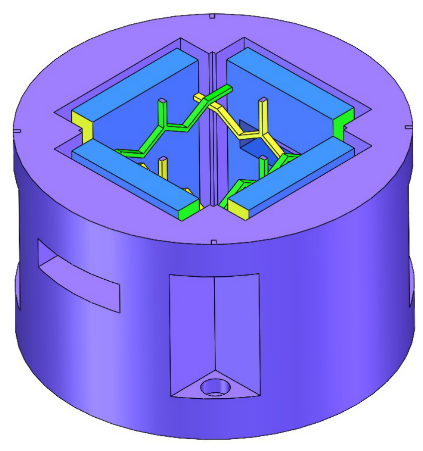
The proposed two-degree-of-freedom compliant tilt stage is designed to realize independent angular motion about two orthogonal axes while suppressing parasitic motion and cross-axis coupling. As shown in Figure 1, the stage mainly consists of an outer fixed frame, a central tilt output unit, and four circumferential compliant motion units. The outer frame provides the mechanical support and installation interface, while the central platform serves as the output end for mounting a mirror or other optical element.
Figure 1.
Two-degree-of-freedom compliant tilt stage. (a) Front view. (b) Cross-sectional view.
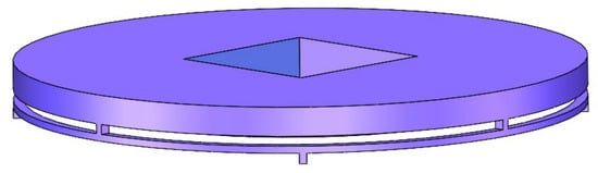
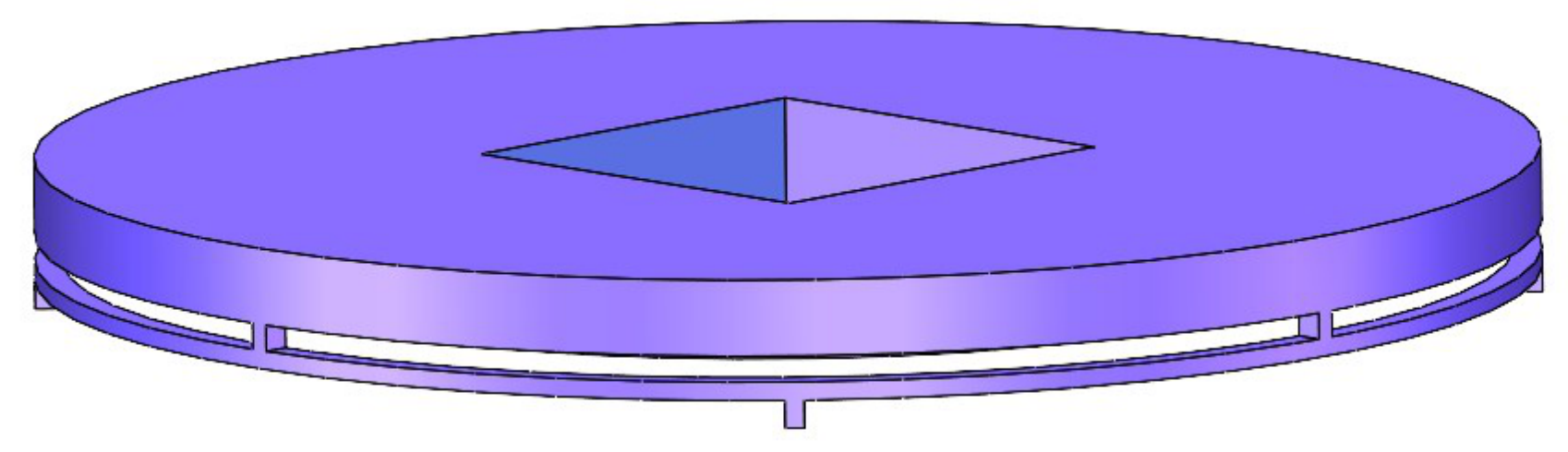
The central tilt output unit is shown in Figure 2. The central platform is directly connected to the surrounding compliant motion units and is supported by compliant decoupling leaf springs. This arrangement allows the central platform to tilt about the desired axis while constraining non-target translational motion. Therefore, the decoupling leaf springs play an important role in improving motion purity and reducing unwanted coupling during dual-axis tilt motion.
Figure 2.
Central tilt output unit.
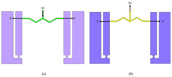
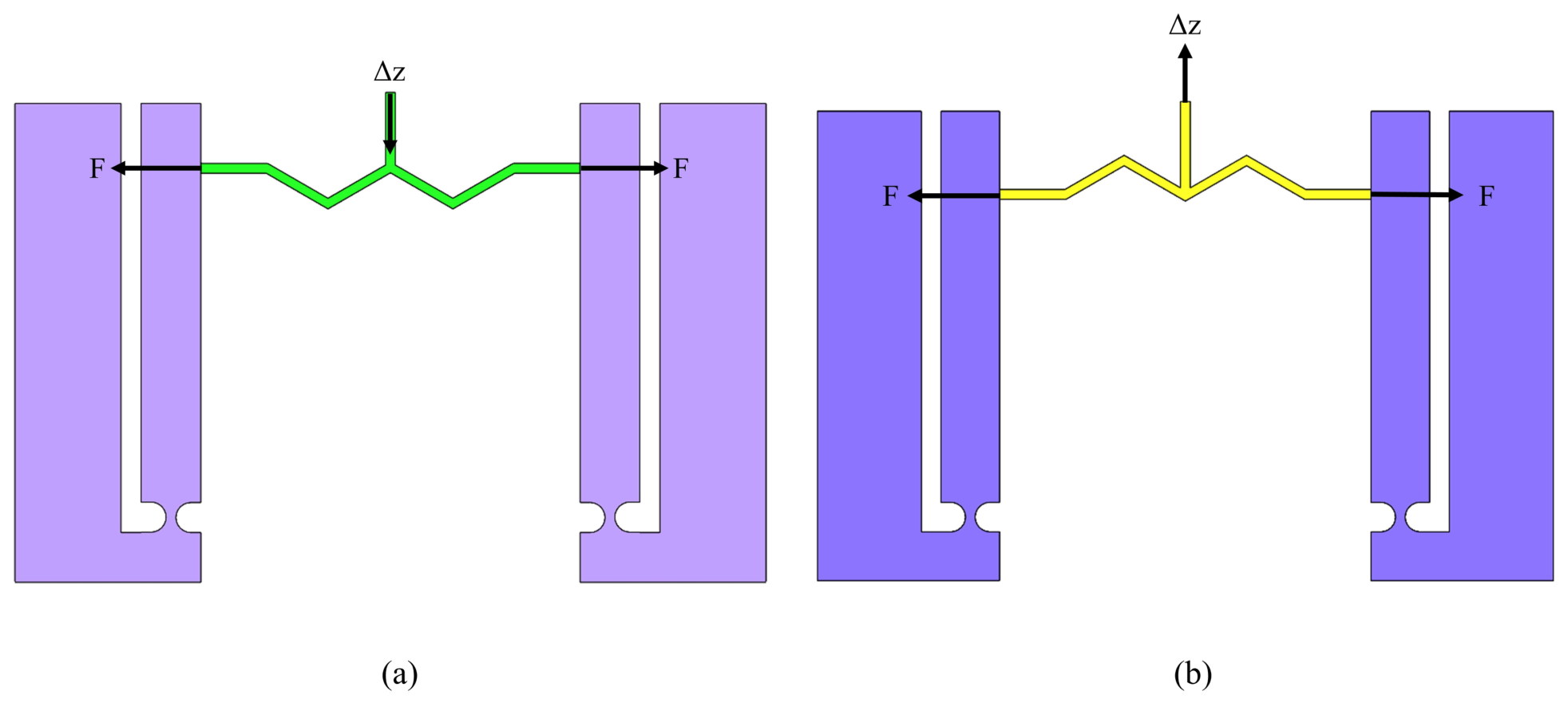
The compliant motion units are developed based on the differential deformation characteristics of positive and negative Poisson’s ratio structures. As shown in Figure 3, a W-shaped positive Poisson’s ratio folded beam and an M-shaped negative Poisson’s ratio folded beam are introduced. Under actuation, these two folded-beam structures exhibit opposite transverse deformation tendencies, which can be used to generate differential motion. Compared with simple straight flexure beams, the folded beam configuration provides a longer equivalent deformation path in a compact space and helps improve the stiffness and constraint capability in non-working directions.
Figure 3.
(a) W-shaped positive Poisson’s ratio structure. (b) M-shaped negative Poisson’s ratio structure.
Each compliant motion unit, as shown in Figure 4, consists of a lever amplification mechanism and a pair of positive and negative Poisson’s ratio folded beams. The lever amplification mechanism is used to enlarge the small displacement generated by the piezoelectric actuator. The amplified displacement is then transmitted to the folded beams, producing coordinated elastic deformation and applying a differential driving effect to the central platform.
Figure 4.
Compliant motion unit.
When one pair of opposite compliant motion units is actuated, the central platform mainly tilts about one horizontal axis. When the other pair is actuated, the stage tilts about the orthogonal horizontal axis. By applying coordinated inputs to the two pairs of motion units, two-axis compound tilt motion can be achieved. Since the motion is generated by distributed elastic deformation rather than rigid joints, the proposed stage avoids friction and backlash, while the decoupling leaf springs help suppress parasitic displacement and improve the stability of dual-axis output.
3. Modeling Analysis
3.1. Modeling Principle
To establish the input–output relationship of the two-degree-of-freedom compliant tilt stage, a static model is developed in this section. The proposed stage mainly consists of positive and negative Poisson’s ratio folded beams, lever amplification mechanisms, compliant decoupling hinges, and a central moving platform. Under the same input force, the M-shaped negative Poisson’s ratio folded beam and the W-shaped positive Poisson’s ratio folded beam generate out-of-plane displacements in opposite directions. As a result, a differential push–pull effect is formed, which drives the central moving platform to tilt about two orthogonal axes. To simplify the theoretical analysis, the following assumptions are made. The material works within the linear elastic range. The flexible beams satisfy the Euler–Bernoulli beam assumption. The lever amplification mechanism and the central moving platform are regarded as rigid bodies. The stage operates within a small-deformation and small-angle range. The W-shaped and M-shaped folded beams are symmetric about their central axes, so half-structure modeling can be used first and then extended to the complete structure. Based on these assumptions, the modeling process can be divided into three parts. First, the equivalent compliance model of the positive and negative Poisson’s ratio folded beams is established. Second, the stiffness of the decoupling hinges and the force transmission relationship of the lever amplification mechanism are derived. Finally, the output tilt angles of the central moving platform are obtained according to force and moment equilibrium.
3.2. Equivalent Stiffness of the Folded Beams
The positive and negative Poisson’s ratio folded beams are the key components for generating differential actuation. During deformation, axial deformation, bending deformation, and torsional deformation occur simultaneously in the folded beams. Therefore, the total strain energy can be expressed as
where , M, and T are the axial force, bending moment, and torque of the beam segment, respectively. E and G are the elastic modulus and shear modulus, respectively. A, I, and are the cross-sectional area, second moment of area, and polar moment of inertia, respectively.
According to Castigliano’s second theorem, the input displacement of the folded beam can be obtained as
Thus, the input compliance and input stiffness are given by
The input force in also causes the output end of the folded beam to move along the main output direction. To describe the coupling relationship between the input force and the output displacement, the input–output coupling compliance is defined as
where g represents the output displacement generated by a unit input force. It is an important parameter for evaluating the driving capability of the folded beam.
For the symmetrically arranged M-shaped and W-shaped folded beams, the main output displacements are opposite under the same input force. Therefore, their coupling compliances can be approximately expressed as
This relationship indicates that the M-shaped negative Poisson’s ratio structure and the W-shaped positive Poisson’s ratio structure can form a push–pull differential actuation effect on both sides of the central moving platform, which is the main mechanism for achieving tilt output.
3.3. Stiffness of the Decoupling Hinges
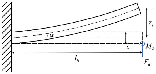
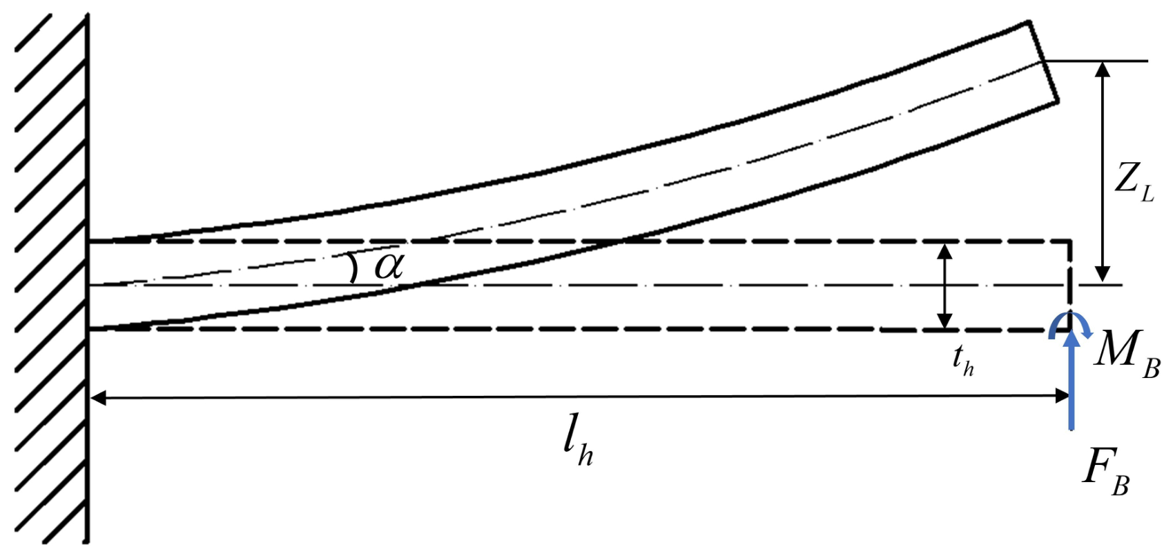
The compliant decoupling hinges connect the central moving platform with the fixed frame. Their function is to allow the desired tilt motion while suppressing parasitic displacement and cross-axis coupling. As shown in Figure 5, a single decoupling hinge can be simplified as a cantilever beam with one fixed end and one loaded end. The second moment of area of the hinge is
where and are the width and thickness of the decoupling hinge, respectively.
Figure 5.
Simplified schematic diagram of the transverse hinge.
When the free end of the decoupling hinge is subjected to an end force and an end moment, the equivalent compliance at the output point can be written as
The corresponding equivalent linear stiffness is
where is the length of the decoupling hinge, and s is the rigid transmission distance between the output point and the hinge connection point.
It can be seen that the hinge stiffness is proportional to the cube of the hinge thickness . Therefore, the hinge thickness has a significant influence on both the tilt compliance and the parasitic-motion-suppression capability. If the hinge is too thick, the tilt output will be restricted. If the hinge is too thin, the resistance to parasitic displacement will decrease.
By transforming the linear stiffness of the decoupling hinges to the central moving platform, the equivalent rotational stiffness about the y-axis and x-axis can be obtained as
Meanwhile, the total constraint stiffness of the four decoupling hinges in the out-of-plane translational direction is
For a folded-beam branch, the output displacement generated by the input force can be expressed as
where and denote the input–output compliances of the M-shaped and W-shaped folded beams, respectively.
Since the M-shaped and W-shaped folded beams exhibit opposite transverse deformation characteristics,
Therefore, the differential displacement generated by one actuation unit can be written as
3.4. Output Angle Model of the Moving Platform
Piezoelectric actuators usually have a large output force but a small output displacement. Therefore, lever amplification mechanisms are introduced into the stage to transmit the piezoelectric driving force to the input ends of the positive and negative Poisson’s ratio folded beams.
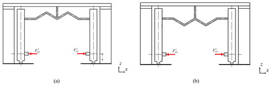
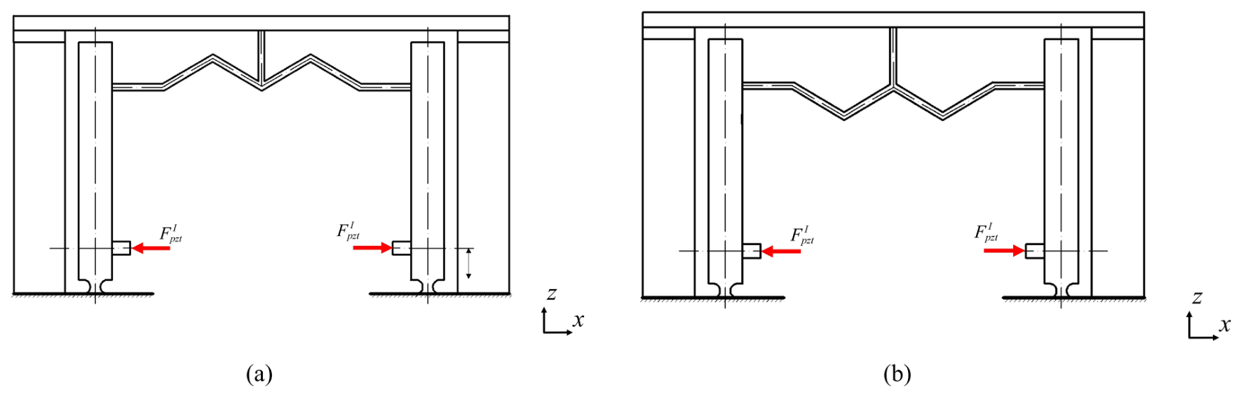
As shown in Figure 6, taking axis I as an example, the output force of the piezoelectric actuator is denoted as , and the corresponding input force of the positive and negative Poisson’s ratio branches is denoted as . Under the symmetric structural condition, the input forces of the M-shaped and W-shaped branches are equal.
Figure 6.
(a) Schematic of the lever amplification mechanism for the axis-I M-shaped structure. (b) Schematic of the lever amplification mechanism for the axis-I W-shaped structure.
According to the force and moment equilibrium of the lever amplification mechanism,
Thus
where
is the force transmission ratio of the lever mechanism.
According to the force equilibrium, moment equilibrium, and deformation compatibility of the lever mechanism, the relationship between the piezoelectric driving force and the branch input force can be simplified as
Similarly, the force transmission relationship for axis II can be written as
where and are the equivalent force transmission coefficients of axis I and axis II, respectively. They are determined by the lever arm lengths, the stiffness of the compliant hinges, and the input compliance of the positive and negative Poisson’s ratio branches. In this paper, these coefficients are used to describe the equivalent force transmission from the piezoelectric actuator to the folded-beam branches.
The differential displacement generated by the positive and negative Poisson’s ratio branches produces an equivalent driving moment on the central moving platform.
For the rotation about the Y-axis, the equivalent driving moment can be expressed as
where denotes the equivalent stiffness of the folded-beam branch and is the distance from the branch output point to the rotational center.
At static equilibrium, the driving moment is balanced by the rotational stiffness of the decoupling hinges,
where is the equivalent rotational stiffness about the Y-axis.
Therefore,
Similarly, for the rotation about the X-axis,
and the rotational equilibrium condition can be expressed as
Therefore,
The central moving platform is regarded as a rigid body. Its motion can be decomposed into an out-of-plane parasitic translation , a tilt angle about the x-axis, and a tilt angle about the y-axis.
When the branches corresponding to axis I are actuated, the M-shaped and W-shaped folded beams generate opposite out-of-plane displacements on both sides of the central moving platform. Therefore, the stage tilts about the y-axis. According to the moment equilibrium of the moving platform, the tilt angle can be expressed as
Similarly, when the branches corresponding to axis II are actuated, the stage tilts about the x-axis, and the tilt angle is
where and are the equivalent moment arms from the branch output points to the tilt center of the stage. and are the input–output coupling compliances of the positive and negative Poisson’s ratio branches. and are the output compliances of the branches. and are the equivalent rotational stiffnesses of the central moving platform. and are the equivalent rotational stiffnesses provided by the decoupling hinges.
Accordingly, the complete input–output relationship of the proposed tilt stage can be obtained as
which are consistent with the final analytical expressions presented below.
Substituting the force transmission relationships into the above equations gives the final relationship between the piezoelectric driving force and the stage tilt angle:
The above equations show that, within the small-deformation range, the output tilt angles are approximately linear with respect to the piezoelectric driving forces. The output performance is mainly affected by the input–output coupling compliance of the folded beams, the force transmission coefficient of the lever mechanism, the output moment arm, the rotational stiffness of the decoupling hinges, and the equivalent rotational stiffness of the central moving platform.
4. Simulation Analysis
4.1. Static Simulation
Finite element simulations were carried out to evaluate the static performance of the proposed two-degree-of-freedom compliant tilt stage. The 3D model was established in SolidWorks 2023 and imported into ANSYS 2022 R2 Workbench for static analysis. The simulation was conducted under standard ambient room temperature conditions (26 °C). The prototype material was defined as an isotropic linear elastic photosensitive resin JLC Black, with a specified Young’s modulus of 2.5 GPa, a Poisson’s ratio of 0.35, and a yield strength of 40 MPa. A Hex-dominant meshing strategy was employed utilizing the higher-order 3D solid element, SOLID186. The element size for all compliant hinge regions was defined as 0.3 mm, while that for the remainder of the mechanism was set to 0.5 mm, yielding approximately 1,040,786 elements and 598,496 nodes. Given the monolithic nature of the compliant stage, no internal contact behaviors or friction coefficients were required to be defined. Subsequently, boundary conditions were applied: a fully fixed constraint was imposed on the base of the tilt stage to restrict all degrees of freedom, and equivalent uniform loads were directly applied to the input ends of the compliant motion units. To ensure a rigorous and equivalent comparison between the numerical simulations and the experimental prototype, the equivalent driving forces applied to the input ends of the lever amplification mechanisms in the FEA were precisely derived based on the stiffness coupling effect. It is well-established that the actual output force of a piezoelectric stack actuator is highly dependent on the opposing mechanical stiffness of the driven load. For the selected piezoelectric actuator with a nominal maximum blocking force of 1960 N and a maximum free stroke of 30 , its internal equivalent stiffness is calculated as . Concurrently, the equivalent input stiffness of the compliant tilt stage was determined through our established analytical compliance model. Under the maximum driving voltage (150 V), the actual input displacement and the effective driving force generated by the actuator satisfy the linear electromechanical equilibrium equation, . By algebraically solving this coupled relationship, the exact magnitude of the applied uniform load in the static simulation was meticulously formulated as .
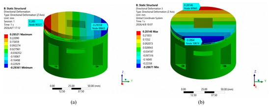
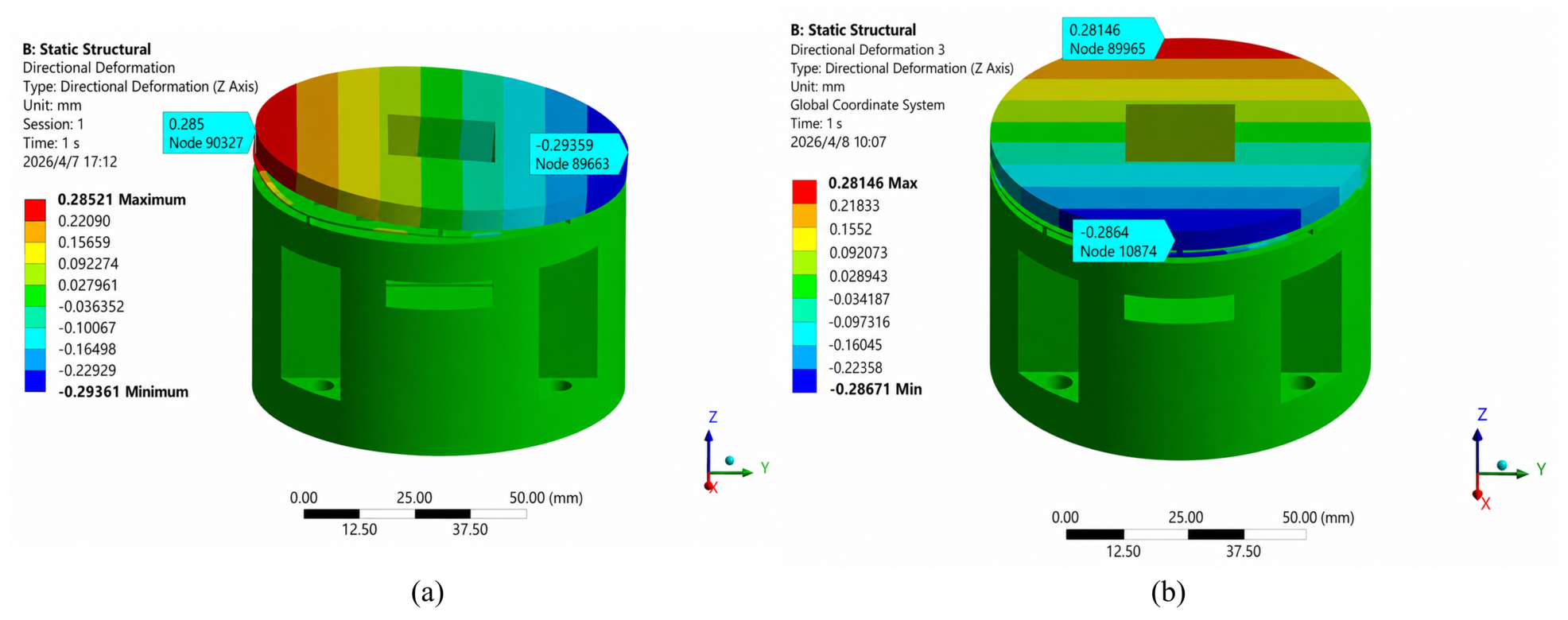
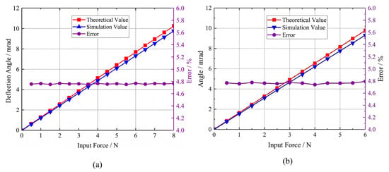
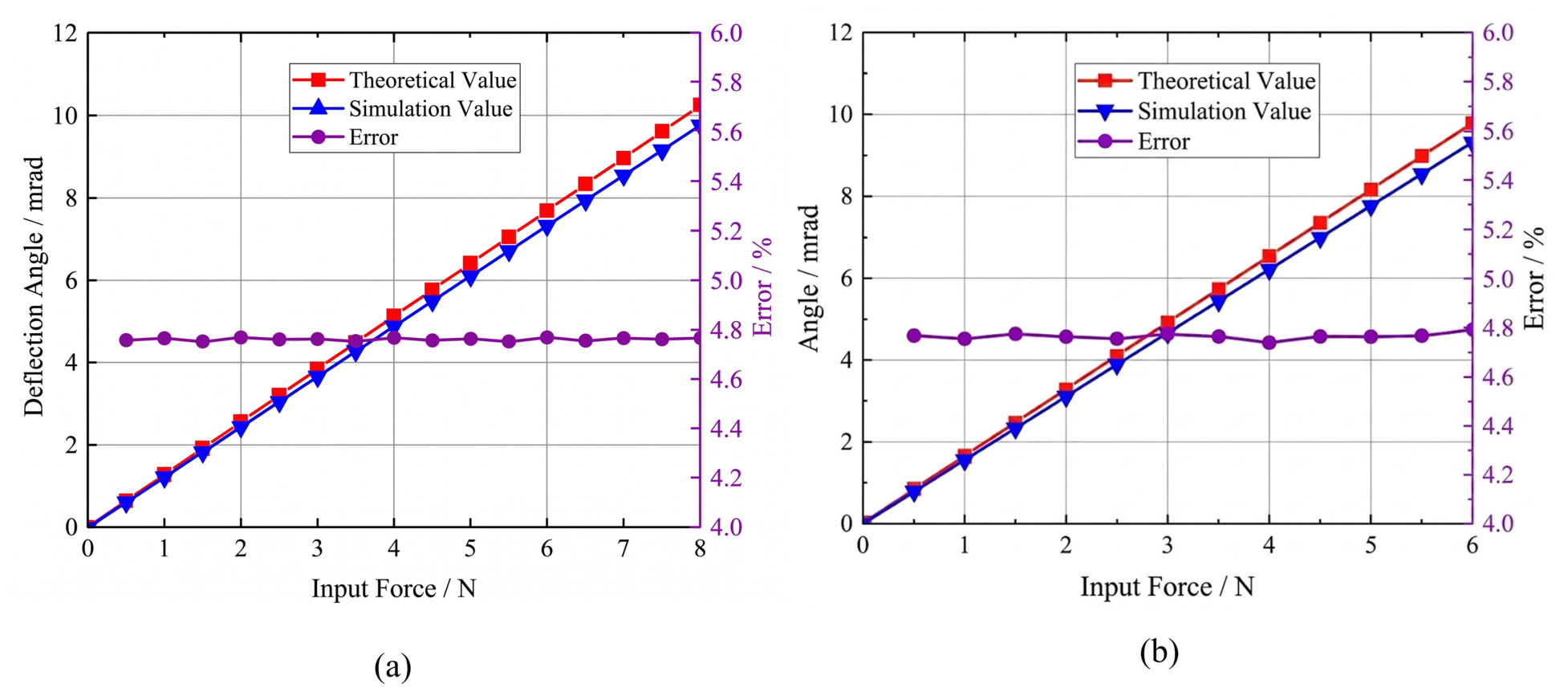
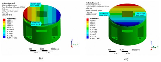
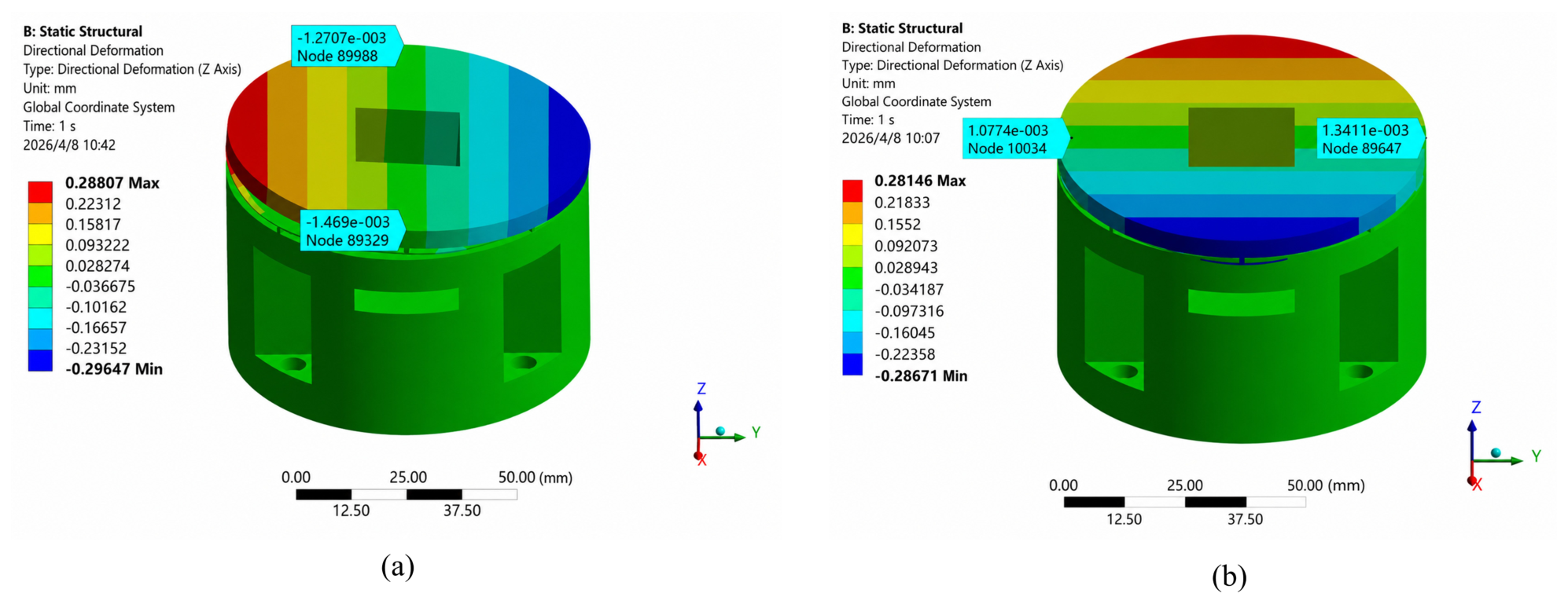
The specific geometric dimensions of the tilt stage are detailed in Table 1. The simulation results are shown in Figure 7. When the stage was actuated about the x-axis and y-axis, the maximum tilt angles were 9.77 mrad and 9.33 mrad, respectively. Compared with the theoretical results of 10.259 mrad and 9.797 mrad, the errors were 4.77% and 4.80%, respectively, as shown in Figure 8. This indicates that the simplified theoretical model can effectively predict the main input–output behavior of the stage.
Table 1.
Geometrical parameters of the tilt stage mechanism.
Figure 7.
Deformation contours of the 2-DOF tilt stage. (a) Tilting about the x-axis. (b) Tilting about the y-axis.
Figure 8.
Comparison between the analytical and FEA results. (a) Tilting about the x-axis. (b) Tilting about the y-axis.
To evaluate the decoupling performance, the parasitic tilt in the non-actuated direction was also extracted. As shown in Figure 9, when the stage tilted about the x-axis, the maximum parasitic tilt about the y-axis was 0.046 mrad. When the stage tilted about the y-axis, the maximum parasitic tilt about the x-axis was 0.042 mrad. Compared with the main angular output, the parasitic tilt was very small, demonstrating the effectiveness of the decoupling leaf springs.
Figure 9.
Coupled displacements of the 2-DOF tilt stage. (a) Tilting about the x-axis. (b) Tilting about the y-axis.
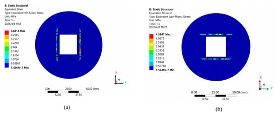
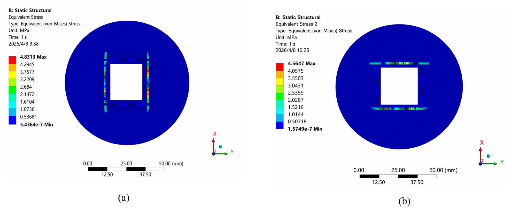
The stress distribution under the maximum tilt condition is shown in Figure 10. The stress was mainly concentrated in the positive and negative Poisson’s ratio folded beams and their connection regions. The maximum equivalent stresses were 4.83 MPa and 4.56 MPa for x-axis and y-axis actuation, respectively, which are much lower than the yield strength of the photosensitive resin material. Therefore, the stage has sufficient strength margin under the designed working range.
Figure 10.
Equivalent stress distribution of the 2-DOF tilt stage. (a) Tilting about the x-axis. (b) Tilting about the y-axis.
4.2. Modal Simulation
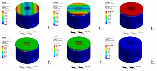
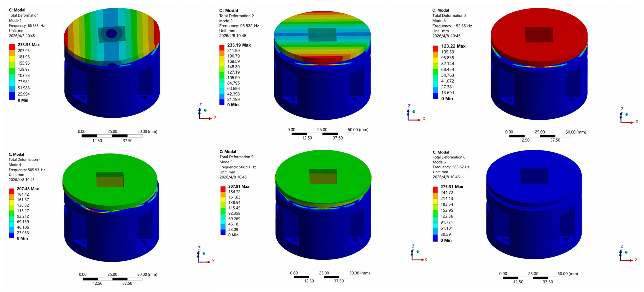
Modal analysis was conducted to investigate the dynamic characteristics of the stage. As shown in Figure 11 and Table 2, the first six natural frequencies were 66.6 Hz, 95.6 Hz, 152.4 Hz, 505.9 Hz, 508.9 Hz, and 563.6 Hz. The first two modes corresponded to the main tilt motions about the two orthogonal axes, while the higher modes were mainly related to out-of-plane or local vibration of the compliant structures. This indicates that the two target tilt motions are the dominant low-order working modes.
Figure 11.
Simulated mode shapes of the 2-DOF tilt stage.
Table 2.
Simulated The first six simulated modal frequencies of the 2-DOF tilt stage.
5. Experimental Verification
To empirically validate the structural integrity and performance metrics predicted by our analytical and numerical models, a physical prototype of the proposed compliant tilt stage was fabricated and subjected to comprehensive static and dynamic testing.
5.1. Experimental Setup
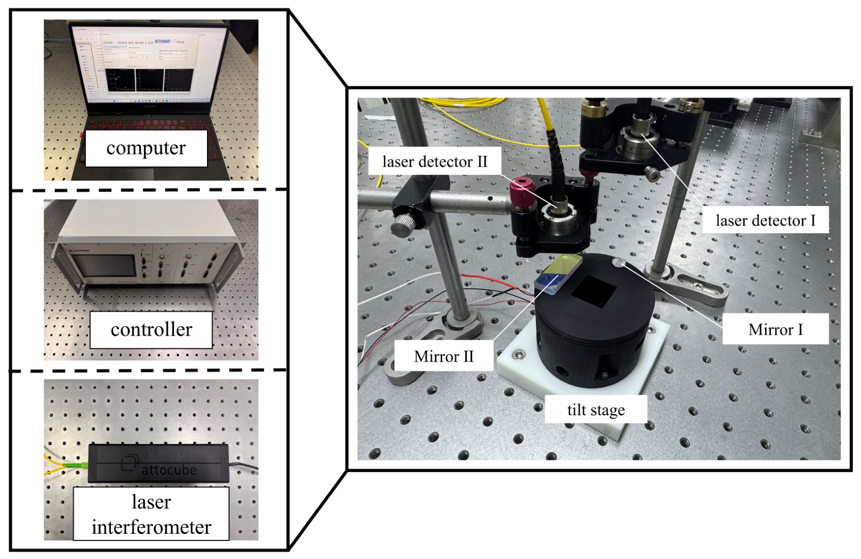
A prototype of the proposed two-degree-of-freedom compliant tilt stage was fabricated using photosensitive resin by stereolithography. A prototype of the proposed two-degree-of-freedom compliant tilt stage was fabricated using stereolithography (SLA) additive manufacturing technology. In this monolithic design, a commercial photosensitive resin, specifically JLC Black, was utilized as the primary structural material. This specific engineering polymer was selected due to its excellent dimensional fidelity and capability to accurately reproduce the micro-features of the delicate compliant leaf springs and folded beams. Following the SLA printing process, the prototype was subjected to a thorough ultrasonic cleaning and an ultraviolet (UV) post-curing treatment to achieve its optimal mechanical properties.The experimental system is shown in Figure 12. A DCS3- 070728C2 multilayer piezoelectric actuator (Guangdong Deci Technology Co., Ltd., Foshan, China) was selected, with dimensions of 7 mm × 7 mm × 28 mm. An IDS 3010 laser interferometer (Attocube Systems AG, Haar, Germany) with a resolution of 0.1 nm was employed as the measurement instrument, and the experimental data were recorded through a data acquisition module. The PZT actuator was driven and controlled by an NPC002-C3 servo controller (Atto Motion Instruments Technology Co., Ltd., Rizhao, China), which executes control commands from the PC and simultaneously collects frequency experimental data. To minimize the influence of environmental vibrations, the entire experimental system was mounted on a vibration-isolated optical platform equipped with pneumatic supports.
Figure 12.
Experimental setup.
5.2. Experimental Results
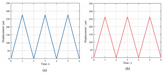
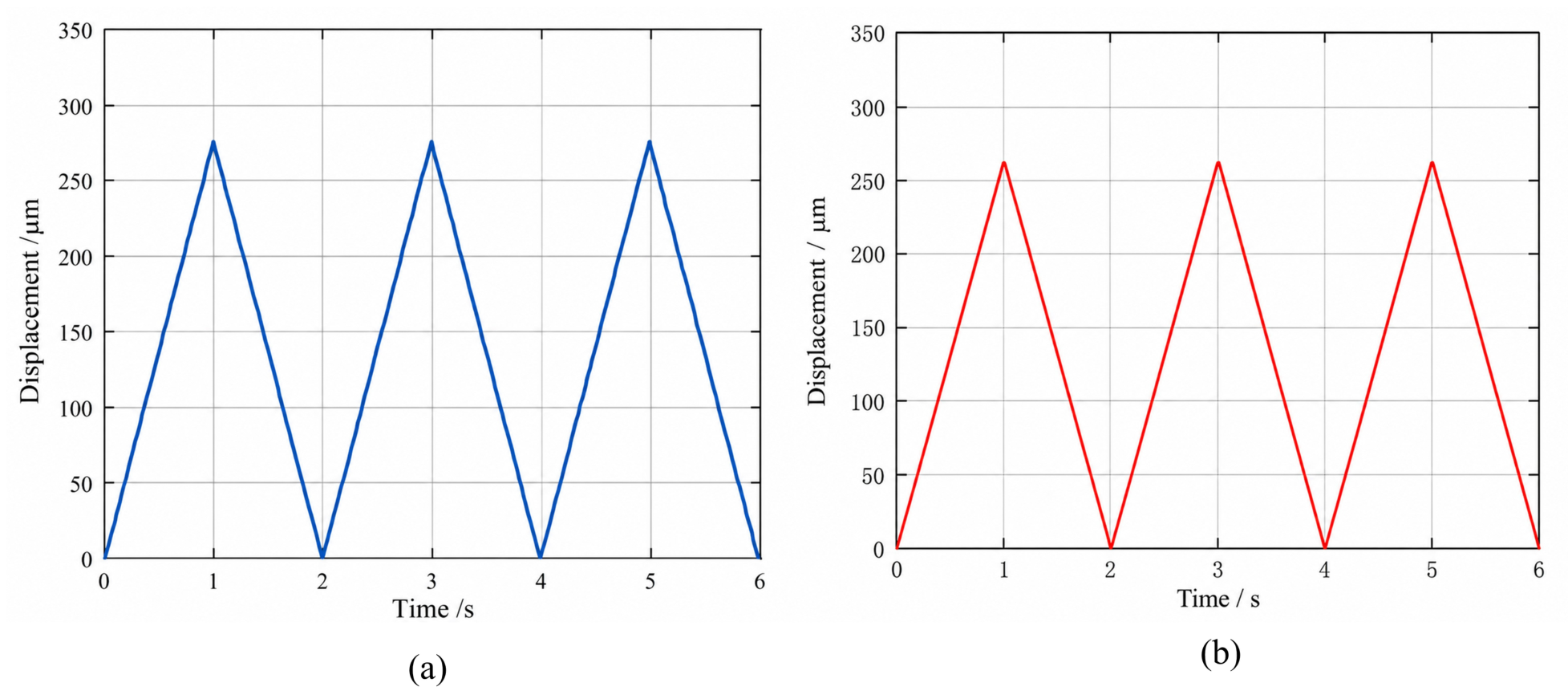
The output stroke of the stage was tested under single-axis actuation. The driving voltage was increased up to 150 V. As shown in Figure 13, the stage produced stable angular output about both axes. The maximum z-direction displacement was 275.91 m for x-axis tilt and 264 m for y-axis tilt. The corresponding maximum tilt angles were 9.19 mrad and 8.8 mrad, respectively.To systematically validate the accuracy of the finite element model, a direct quantitative comparison between the simulation predictions and the experimental measurements was conducted. Under the maximum driving conditions, the FEA simulated peak tilt angles were 9.77 mrad and 9.33 mrad for the x- and y-axes, respectively. Correspondingly, the experimental prototype achieved actual maximum tilt angles of 9.19 mrad and 8.80 mrad. The calculated relative errors between the theoretical simulation and the empirical results are approximately 5.9% for the x-axis and 5.6% for the y-axis. These minor discrepancies are well within the acceptable engineering margin and can be primarily attributed to two factors: the manufacturing dimensional tolerances inherent in the SLA 3D printing process, which slightly alter the actual thickness of the delicate compliant leaf springs, and the subtle deviations between the actual elastic modulus of the post-cured resin and the nominal material parameters utilized in the simulation.
Figure 13.
Experimental stroke of the 2-DOF tilt stage. (a) Tilting about the x-axis. (b) Tilting about the y-axis.
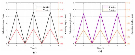
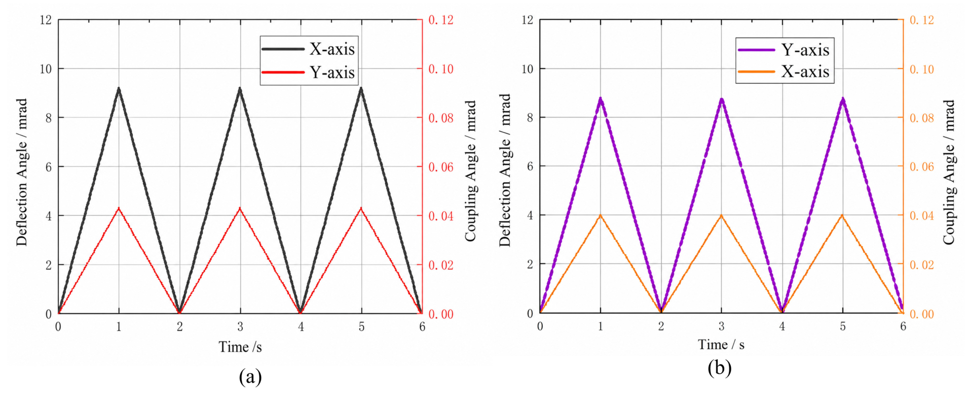
The parasitic tilt in the non-actuated direction was also measured. As shown in Figure 14, the coupling angles were 0.043 mrad and 0.04 mrad under maximum output conditions. These values are much smaller than the main tilt angles, indicating good decoupling performance.
Figure 14.
Measured primary tilting and cross-axis coupling angles of the 2-DOF tilt stage. (a) Tilting about the x-axis. (b) Tilting about the y-axis.
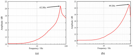
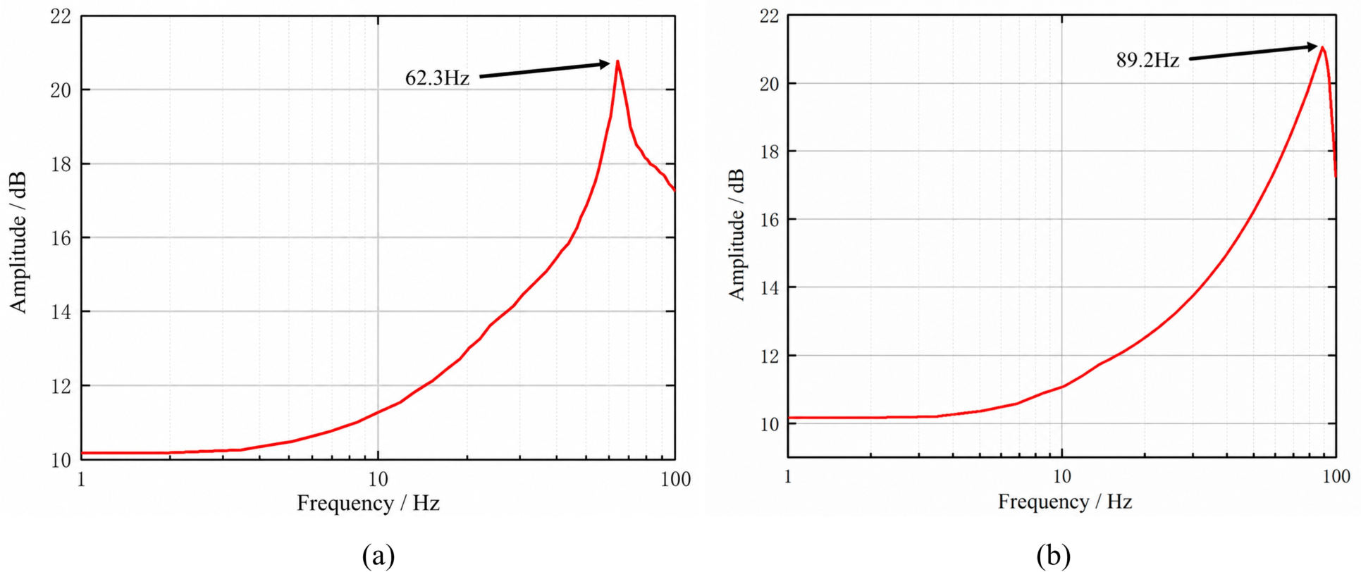
Frequency response tests were conducted to evaluate the dynamic performance of the prototype. A small-amplitude sinusoidal sweep signal was applied to the piezoelectric actuators, and the dynamic displacement response of the central platform was measured. As shown in Figure 15, the first resonant frequencies were 89.2 Hz about the x-axis and 62.3 Hz about the y-axis. The experimental resonant frequencies were slightly lower than the simulated values, mainly due to manufacturing errors, material uncertainty, and non-ideal boundary stiffness in the experimental setup.
Figure 15.
Measured frequency response curves of the 2-DOF tilt stage. (a) Tilting about the y-axis. (b) Tilting about the x-axis.
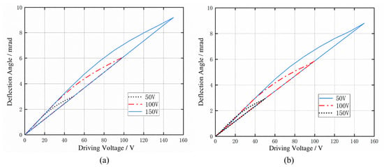
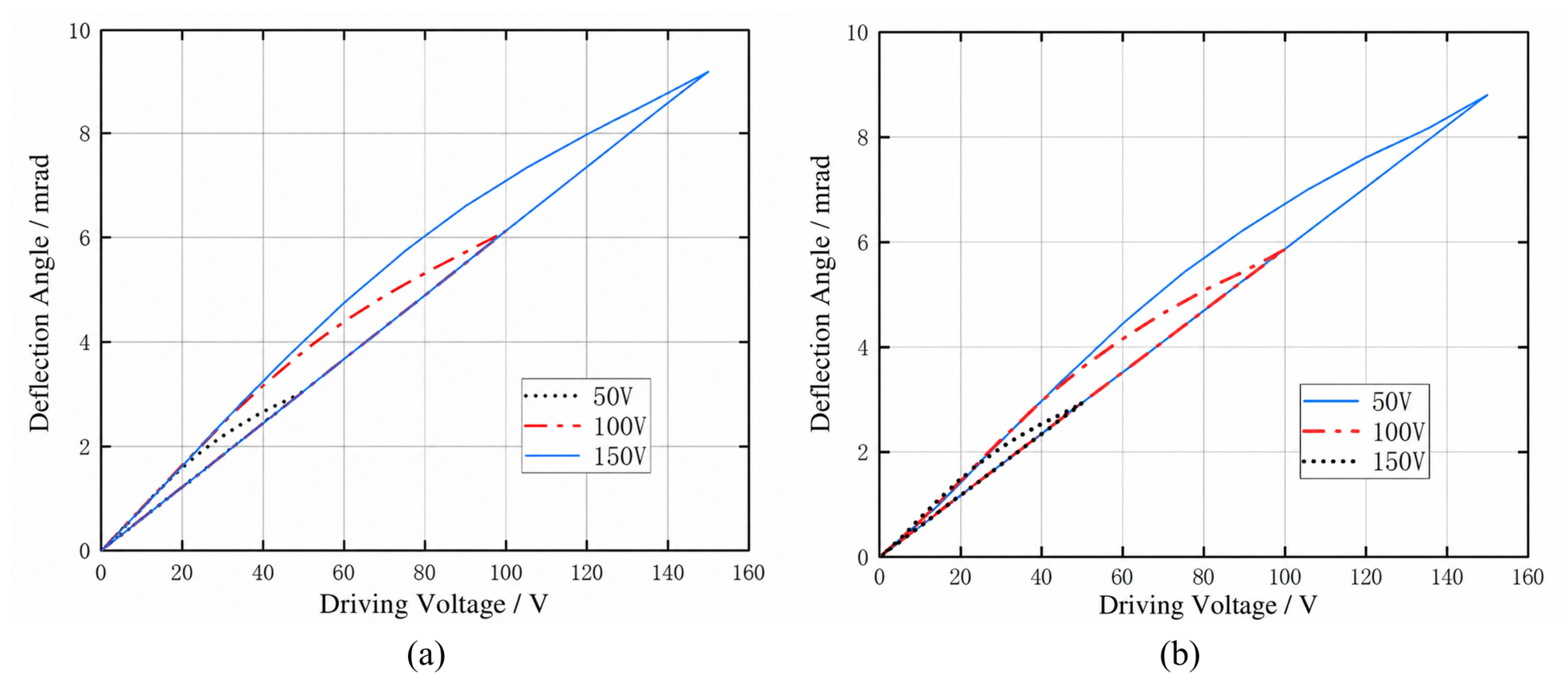
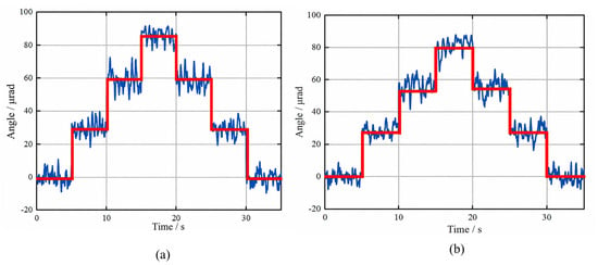
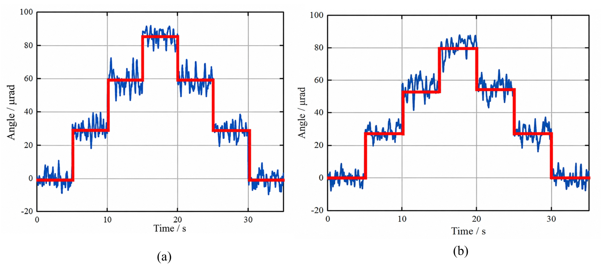
The hysteresis characteristics were tested by applying triangular voltage signals with amplitudes of 50 V, 100 V, and 150 V. As shown in Figure 16, clear hysteresis loops were observed in both actuation directions. For x-axis actuation, the maximum hysteresis widths were approximately 0.36 mrad, 0.85 mrad, and 1.19 mrad. For y-axis actuation, the corresponding values were approximately 0.34 mrad, 0.75 mrad, and 0.89 mrad. The hysteresis increased with the driving voltage, mainly due to the inherent nonlinear behavior of the piezoelectric actuators. The open-loop resolution was tested using step voltage inputs. As shown in Figure 17, the minimum resolvable angular displacements were 30 rad about the x-axis and 27 rad about the y-axis.
Figure 16.
Measured hysteresis loops of the 2-DOF tilt stage. (a) Tilting about the x-axis. (b) Tilting about the y-axis.
Figure 17.
Measured resolution of the 2-DOF tilt stage(The blue line represents the measured values, and the red line represents the average.). (a) Tilting about the x-axis. (b) Tilting about the y-axis.
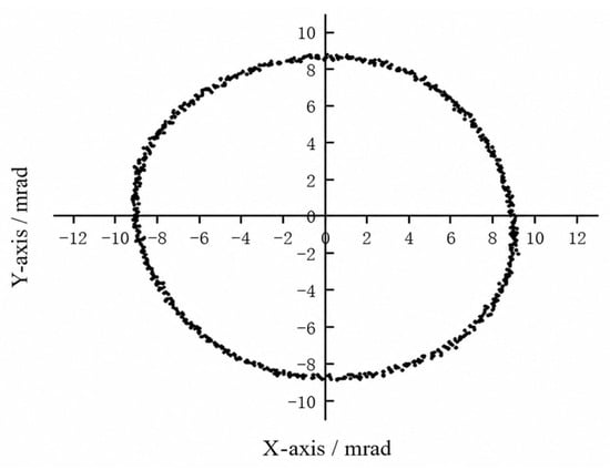
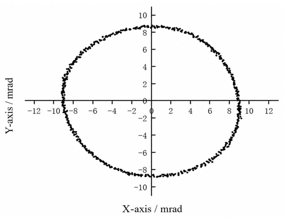
To verify the two-axis scanning capability, sinusoidal voltages with the same amplitude of 150 V and a phase difference of were applied to the two actuation directions. As shown in Figure 18, the stage generated a stable two-dimensional trajectory with an approximately elliptical shape. The maximum tilt ranges were about 9.19 mrad and 8.8 mrad about the x- and y-axes, respectively. The deviation from an ideal circular trajectory may be caused by residual cross-axis coupling, signal synchronization error, and external disturbance.
Figure 18.
Measured motion trajectories of the 2-DOF tilt stage.
The comparison results in Table 3 indicate that while some existing stages exhibit high dynamic performance and excellent decoupling capabilities, they often require multiple actuators or complex structural layouts. Conversely, other designs achieve structural compactness at the expense of a limited output stroke. In contrast, the proposed 2-DOF compliant tilt stage achieves a large dual-axis angular output utilizing only two actuators while maintaining low cross-axis coupling errors. This demonstrates a favorable trade-off among structural compactness, actuation simplification, and overall performance. Consequently, the design strategy—integrating the differential actuation of positive and negative Poisson’s ratio folded beams with compliant decoupling—is proven effective in enhancing the comprehensive performance of dual-axis tilt stages.
Table 3.
Performance comparison among various tilt stages.
To further validate the design, a direct comparison between the analytical, finite element, and experimental results is necessary. Under the nominal driving voltage of 150 V—which is well within the standard and safe operational range for commercial multi-layer piezoelectric stack actuators—the simulated maximum tilt angles were 9.77 mrad and 9.33 mrad for the x- and y-axes, respectively. In comparison, the experimentally measured maximum tilt angles reached 9.19 mrad and 8.80 mrad. The relative errors between the FEA predictions and the experimental outputs are merely 5.9% and 5.6%. These minor discrepancies can be primarily attributed to the dimensional tolerances inherent in the SLA 3D printing process and slight variations in the actual elastic modulus of the cured resin compared to the nominal values. Furthermore, regarding the energy efficiency of the proposed stage, the piezoelectric actuators primarily act as capacitive loads.
6. Conclusions
We have developed and validated a novel two-degree-of-freedom compliant tilt stage that leverages the differential deformation of W-shaped positive and M-shaped negative Poisson’s ratio structures. By integrating these folded beams with lever amplifiers and decoupling leaf springs, the design intrinsically translates identical input forces into opposite out-of-plane deformations, yielding independent and highly decoupled orthogonal tilt motions. Our derived static analytical models, which closely align with finite element predictions under a 5% error margin, successfully capture the system’s mechanics. Stereolithography-fabricated prototypes empirically confirmed these theoretical frameworks, delivering robust maximum tilt angles of 9.19 mrad and 8.80 mrad at 150 V while restricting cross-axis coupling to strictly negligible levels below 0.05 mrad. Although the current study successfully validates the kinematic decoupling and basic resonant behavior of the proposed mechanism, comprehensive dynamic characterization and active control strategies are imperative for its ultimate application in precision optical systems. The open-loop positioning accuracy of the stage is inevitably compromised by the inherent hysteresis and creep behaviors of the piezoelectric actuators. To achieve high-fidelity trajectory tracking and accurately quantify critical dynamic metrics—such as settling time, damping ratio, transient step response, and operational bandwidth—subsequent research will focus on the development of a robust closed-loop control system. This system will integrate a proportional–integral–derivative (PID) feedback controller with an advanced feedforward hysteresis compensation model to effectively suppress the nonlinearities of the piezoelectric drive. Furthermore, the current monolithic prototype was fabricated from photosensitive resin, which serves excellently for rapid proof-of-concept validation but poses significant risks of mechanical creep, fatigue failure, and thermal instability under continuous operation. To transition this design into a commercially viable industrial solution, future physical iterations will be manufactured utilizing metallic additive manufacturing technologies. Specifically, adopting metallic materials such as the AlSi10Mg aluminum alloy via selective laser melting (SLM) will not only eliminate the long-term reliability issues associated with polymers but also drastically enhance the structural rigidity, thermal stability, and fatigue life of the compliant tilt stage, thereby ensuring its enduring performance in demanding optical beam steering applications.
Author Contributions
Conceptualization, X.H.; Methodology, X.H.; Software, X.H.; Validation, X.H. and Y.M.; Writing—original draft, X.H.; Writing—review & editing, X.H., L.M. and P.L.; Visualization, L.M. and P.L.; Supervision, L.M., Y.M., P.L. and P.Y.; Project administration, P.L. and P.Y.; Funding acquisition, P.L. and P.Y. All authors have read and agreed to the published version of the manuscript.
Funding
The authors disclosed receipt of the following financial support for the research, authorship, and/or publication of this article: This work was supported by the Key Research and Development Program of Shandong Province (grant Nos. 2025CXGC011105, 2022CXPT029 and 2023CXPT014), the Major Innovation Project of Qilu University of Technology (Shandong Academy of Sciences) (grant No. 2025 ZDZX03), the Natural Science Foundation of Shandong Province (grant Nos. ZR2022QE235 and ZR2024QE394).
Data Availability Statement
The data that support the findings of this study are available from the corresponding author upon reasonable request.
Acknowledgments
During the preparation of this manuscript/study, the author(s) used OpenAI GPT-5.4 for the purposes of language embellishment.
Conflicts of Interest
The authors declare no conflicts of interest.
References
- Jahid, A.; Alsharif, M.H.; Hall, T.J. A contemporary survey on free space optical communication: Potentials, technical challenges, recent advances and research direction. J. Netw. Comput. Appl. 2022, 200, 103311. [Google Scholar] [CrossRef] [Scilit]
- Khalighi, M.A.; Uysal, M. Survey on free space optical communication: A communication theory perspective. IEEE Commun. Surv. Tutor. 2014, 16, 2231–2258. [Google Scholar] [CrossRef] [Scilit]
- Hardy, J.W. Adaptive Optics for Astronomical Telescopes; Oxford University Press: New York, NY, USA, 1998. [Google Scholar]
- Tyson, R.K. Principles of Adaptive Optics, 4th ed.; CRC Press: Boca Raton, FL, USA, 2015. [Google Scholar]
- Milaševičius, M.; Mačiulis, L. A review of mechanical fine-pointing actuators for free-space optical communication. Aerospace 2023, 11, 5. [Google Scholar]
- Aigouy, G.; Guignabert, A.; Betsch, E.; Cote, C.; Rebufa, J.; De Lepine, X.; Fournier, M.; Duc, S.; Sosnicki, O.; Personnat, P.; et al. Large stroke fast steering mirror for free-space optical communication. In Proceedings of the International Conference on Space Optics—ICSO 2020; SPIE: Bellingham, WA, USA, 2021; p. 118525O. [Google Scholar]
- Howell, L.L. Compliant Mechanisms; Wiley-Interscience: New York, NY, USA, 2001. [Google Scholar]
- Smith, S.T. Flexures: Elements of Elastic Mechanisms; Gordon and Breach Science Publishers: London, UK, 2000. [Google Scholar]
- Lobontiu, N. Compliant Mechanisms: Design of Flexure Hinges; CRC Press: Boca Raton, FL, USA, 2002. [Google Scholar]
- Du, Z.; Shi, R.; Dong, W. A piezo-actuated high-precision flexible parallel pointing mechanism: Conceptual design, development, and experiments. IEEE Trans. Robot. 2014, 30, 131–137. [Google Scholar] [CrossRef] [Scilit]
- Gu, G.Y.; Zhu, L.M.; Su, C.Y.; Ding, H.; Fatikow, S. Modeling and control of piezo-actuated nanopositioning stages: A survey. IEEE Trans. Autom. Sci. Eng. 2016, 13, 313–332. [Google Scholar] [CrossRef] [Scilit]
- Zhou, Z.; Feng, Z.; Xian, H.; Huang, L. Single preloaded piezoelectric-ceramic-stack-actuator-based fast steering mirror with an ultrahigh natural frequency. Appl. Opt. 2020, 59, 3871–3877. [Google Scholar] [CrossRef] [Scilit] [PubMed]
- Ozaki, T.; Ohta, N.; Fujiyoshi, M. Highly linear and wide non-resonant two-degree-of-freedom piezoelectric laser scanner. Sensors 2022, 22, 4215. [Google Scholar] [CrossRef] [Scilit] [PubMed]
- Jeon, S.; Toshiyoshi, H. MEMS tracking mirror system for a bidirectional free-space optical link. Appl. Opt. 2017, 56, 6720–6727. [Google Scholar] [CrossRef] [Scilit] [PubMed]
- Park, J.H.; Lee, H.S.; Lee, J.H.; Yun, S.N.; Ham, Y.B.; Yun, D.W. Design of a piezoelectric-driven tilt mirror for a fast laser scanner. Jpn. J. Appl. Phys. 2012, 51, 09MD14. [Google Scholar] [CrossRef] [Scilit]
- Kim, H.S.; Lee, D.H.; Hur, D.J.; Lee, D.C. Development of two-dimensional piezoelectric laser scanner with large steering angle and fast response characteristics. Rev. Sci. Instrum. 2019, 90, 065004. [Google Scholar] [CrossRef] [Scilit] [PubMed]
- Zhong, J.; Nishida, R.; Shinshi, T. Design and precision tracking control of a high-bandwidth fast steering mirror for laser beam machining. Precis. Eng. 2022, 73, 128–139. [Google Scholar] [CrossRef] [Scilit]
- Yang, Y.; Liu, Y.; Su, Y.; Weng, Z.; Sun, Q.; Qiao, Q.; Xue, W.; Zhang, Y.; Wang, Y.; Wang, L.; et al. MEMS fast steering mirror with a large optical aperture and high surface quality for free-space optical communication. Opt. Express 2024, 32, 37932–37945. [Google Scholar] [CrossRef] [Scilit] [PubMed]
- Xue, W.; Liu, Y.; Zhu, X.; Yang, Y.; Su, Y.; Zhang, Y.; Wang, Y.; Zhao, Q.; Wu, Z. A high-performance 10 mm diameter MEMS fast steering mirror with integrated piezoresistive angle sensors for laser inter-satellite links. Microsyst. Nanoeng. 2025, 11, 75. [Google Scholar] [CrossRef] [Scilit] [PubMed]
- Han, W.; Zhai, C.; Shao, S.; Tian, Z.; Lu, Q.; Zhang, S.; Xu, M. Piezoelectric-based large-angle stroke fast steering mirror with high ratio of output range to resolution and self-sensing capability. Rev. Sci. Instrum. 2024, 95, 085005. [Google Scholar] [CrossRef] [Scilit] [PubMed]
- Chang, Q.; Chen, W.; Liu, J.; Yu, H.; Deng, J.; Liu, Y. Development of a novel two-DOF piezo-driven fast steering mirror with high stiffness and good decoupling characteristic. Mech. Syst. Signal Process. 2021, 159, 107851. [Google Scholar] [CrossRef] [Scilit]
- Han, W.; Shao, S.; Zhang, S.; Tian, Z.; Xu, M. Design and modeling of decoupled miniature fast steering mirror with ultrahigh precision. Mech. Syst. Signal Process. 2022, 167, 108521. [Google Scholar] [CrossRef] [Scilit]
- Yuan, G.; Li, S.D. Single piezoelectric ceramic stack actuator based fast steering mirror with fixed rotation axis and large excursion angle. Sens. Actuators A Phys. 2015, 235, 292–299. [Google Scholar] [CrossRef] [Scilit]
- Liang, C.; Wang, F.; Huo, Z.; Shi, B.; Tian, Y.; Zhao, X.; Zhang, D. A 2-DOF monolithic compliant rotation platform driven by piezoelectric actuators. IEEE Trans. Ind. Electron. 2020, 67, 6963–6974. [Google Scholar] [CrossRef] [Scilit]
- Li, S.; Jia, B.; Wang, L.; An, H.; Zhang, D.; Wang, R.; Zhao, C. Development of a large stroke 3-DOF piezoelectric steering mirror for optical system. Sens. Actuators A Phys. 2024, 378, 115824. [Google Scholar] [CrossRef] [Scilit]
- Kim, J.G. System integration design of high-performance piezo-actuated fast-steering mirror for laser beam steering system. Sensors 2024, 24, 6775. [Google Scholar] [CrossRef] [Scilit] [PubMed]
- Li, X.; Jing, Z.; Wang, J.; Meng, F.; Li, H.; Xie, Z.; Luo, J.; Mao, Y.; Qi, B. A fast steering mirror with large tilting angle, high natural frequency and high resolution driven by the dual mode actuators. Sens. Actuators A Phys. 2025, 382, 116118. [Google Scholar] [CrossRef] [Scilit]
- Zhang, W.; Yuan, J.; Yan, C.; Gao, Z.; Dong, Y. Multi-objective optimization design of natural frequency of two-degree-of-freedom fast steering mirror system. IEEE Access 2021, 9, 33689–33703. [Google Scholar] [CrossRef] [Scilit]
- Ni, Z.; Zhang, D.; Wu, Y.; Tian, Y.; Hu, M. Analysis of parasitic motion in parallelogram compliant mechanism. Precis. Eng. 2010, 34, 133–138. [Google Scholar] [CrossRef] [Scilit]
- Qin, Y.; Shirinzadeh, B.; Tian, Y.; Zhang, D. Design issues in a decoupled XY stage: Static and dynamics modeling, hysteresis compensation, and tracking control. Sens. Actuators A Phys. 2013, 194, 95–105. [Google Scholar] [CrossRef] [Scilit]
- Chen, W.; Chen, S.; Qu, J.; Chen, W. A large-range compliant remote center of motion stage with input/output decoupling. Precis. Eng. 2018, 51, 468–480. [Google Scholar] [CrossRef] [Scilit]
- Hao, G.; Yu, J. Design, modelling and analysis of a completely-decoupled XY compliant parallel manipulator. Mech. Mach. Theory 2016, 102, 179–195. [Google Scholar] [CrossRef] [Scilit]
- Chen, X.; Li, Y. Design and analysis of a new high precision decoupled XY compact parallel micromanipulator. Micromachines 2017, 8, 82. [Google Scholar] [CrossRef] [Scilit] [PubMed]
- Shi, H.; Yang, G.; Li, H.N.; Zhao, J.; Yu, H.; Zhang, C. A flexure-based and motion-decoupled XYZ nano-positioning stage with a quasi-symmetric structure. Precis. Eng. 2024, 89, 1–14. [Google Scholar] [CrossRef] [Scilit]
- Zhang, Q.; Dong, W.; Xu, Q.; Goteea, B.J.; Gao, Y. FlexDelta: A flexure-based fully decoupled parallel XYZ positioning stage with a long stroke. Precis. Eng. 2024, 89, 178–190. [Google Scholar] [CrossRef] [Scilit]
- Pham, M.T.; Yeo, S.H.; Teo, T.J.; Yang, G.; Lin, W.; Chen, I.M. A decoupled 6-DOF compliant parallel mechanism with optimized dynamic characteristics using cellular structure. Machines 2021, 9, 5. [Google Scholar] [CrossRef] [Scilit]
- Gallardo, A.G.; Pucheta, M.A. Synthesis of parallel flexure stages with decoupled actuators using sum, intersection, and difference of screw systems. Mech. Mach. Theory 2024, 193, 105530. [Google Scholar]
- Wu, H.; Lai, L.; Zhang, L.; Zhu, Y. A novel compliant XY micro-positioning stage using bridge-type displacement amplifier embedded with Scott-Russell mechanism. Precis. Eng. 2022, 73, 385–397. [Google Scholar] [CrossRef] [Scilit]
- Shao, S.; Tian, Z.; Song, S.; Xu, M. Two-degrees-of-freedom piezo-driven fast steering mirror with cross-axis decoupling capability. Rev. Sci. Instrum. 2018, 89, 055003. [Google Scholar] [CrossRef] [Scilit] [PubMed]

Disclaimer/Publisher’s Note: The statements, opinions and data contained in all publications are solely those of the individual author(s) and contributor(s) and not of MDPI and/or the editor(s). MDPI and/or the editor(s) disclaim responsibility for any injury to people or property resulting from any ideas, methods, instructions or products referred to in the content. |
© 2026 by the authors. Licensee MDPI, Basel, Switzerland. This article is an open access article distributed under the terms and conditions of the Creative Commons Attribution (CC BY) license.