


Abstract
Modern logistics and manufacturing environments simultaneously demand mobility platforms that are compact enough to navigate narrow aisles and powerful enough to transport oversized or heavy components. We previously developed a compact Steering–Drive–Suspension (SDS) module that integrates steering, in-wheel drive, and suspension within a single wheel envelope, achieving wide-angle steering with a single actuator. The present paper extends that hardware-centric work by treating the two-wheel (2WD) configuration assembled from two SDS modules as the unit module of the platform, building a four-wheel (4WD) operation by coupling two such 2WD units, and developing a unified balance and impedance-based control scheme. We derive a cart–pole inverted-pendulum model for the 2WD configuration and a planar 2-DOF bicycle model for the coupled and cooperative configurations, with full controllability proof and quantitative LQR robustness margins. Three Python 3.12 based scenarios validate the framework: (i) a 2WD inverted-pendulum tracking task, (ii) a forward and lateral relocation maneuver compared across SDS Crab, Ackermann, and four-wheel-steering modes, and (iii) cooperative transport of a steel plate by two impedance-coupled 2WD units. Across all scenarios the proposed controllers achieve sub-centimetre tracking gap, pitch deviation within , and well-damped cooperative behavior without payload sloshing. The results substantiate the central design claim that the SDS module’s compactness enables a single hardware platform to act simultaneously as an autonomous small-payload mover, a building block of a 4WD platform, and a cooperative agent for oversized loads.
1. Introduction
1.1. Background and Motivation
Modern logistics, factory automation, and indoor service environments place two competing demands on mobility platforms: they must be compact enough to navigate narrow aisles and human-shared workspaces, yet powerful enough to transport oversized or heavy components when needed. A single fixed-form-factor automated guided vehicle (AGV) typically satisfies one of these demands at the expense of the other. Reconfigurable platforms, capable of changing wheel count, footprint, or geometry on demand, promise to break this trade-off, but achieving such reconfigurability with a compact and modular hardware design has remained an open problem.
1.2. Related Work
Reconfigurable mobility hinges on the wheel-side integration of steering, drive, and suspension. Our prior work [1] introduced a compact Steering-Drive-Suspension (SDS) module with wide-angle steering driven by a single actuator. Comparable corner-module architectures, such as REEcorner, the Hyundai e-Corner system, and the Rajaie corner module, package steering, drive, and suspension into a single wheel-side unit, yet most existing designs are constrained to a single wheel count and a limited steering range. At the vehicle level, four-wheel independent-drive and independent-steering (4WID/4WIS) electric platforms have been studied extensively, including hierarchical motion control of corner-module configurations [2], surveys of configuration and control [3], in-wheel-motor drive systems [4], integrated stability control [5], and path tracking [6], while dedicated omnidirectional steering interfaces [7] and multi-mode motion planners [8] exploit the additional actuation degrees of freedom.
Inverted-pendulum two-wheel mobility, exemplified by the JOE platform [9] and Segway-class vehicles, demonstrates that compact two-wheel units can serve as autonomous transport agents; their nonholonomic dynamics [10], modelling and control approaches [11], and recent wheel-based realizations [12] are well documented. The lateral behaviour of the upright platform is captured by classical vehicle-dynamics theory [13,14], with tyre forces described by the Magic Formula [15,16]. For trajectory tracking of wheeled mobile robots, model-based and robust schemes including kinematic modelling and control [17], sliding-mode tracking [18], and model-predictive path following [19] are well established.
Cooperative transport of large payloads by multiple mobile robots commonly relies on interaction control. Impedance control [20] and the operational-space formulation [21] established the foundations of force-compliant manipulation, later surveyed and extended through force control [22] and variable-impedance learning [23]. At the multi-robot level, communication-free force-amplifying transport [24], occlusion-based cooperative transport [25], and broader surveys of cooperative object transport [26] show that distributed agents can move shared loads without rigid coupling. Finally, modular self-reconfigurable robot systems [27,28] motivate the unit-module philosophy adopted here, while cloud-robotics frameworks [29] provide the mission-level context for coordinating heterogeneous mobility agents.
1.3. Relation to Prior Work
Our JMR study [1] addressed mechanism design, kinematic analysis, and hardware experiments at the single-module and four-module-platform levels. The dynamics of the resulting platform, the balance control needed when the platform is built from only two wheels, and the cooperative control needed when two such 2WD units transport a shared payload were left as open problems. The conference work [30] introduced a yaw-moment observer (YMO) for postural and lateral control. The present paper directly addresses the unsolved questions: it formulates the 2WD inverted-pendulum dynamics and the planar bicycle dynamics relevant to the SDS-based platform, augments the YMO with a Linear-Quadratic-Regulator (LQR) balance loop and an admittance-based cooperative loop, and validates three reconfiguration scenarios in simulation. To delineate the boundary with our previous publications explicitly: the mechanism design, kinematic analysis, and module-level hardware of the SDS belong to [1], and the yaw-moment observer belongs to [30]; everything downstream of the 2WD-as-unit-module decision is new to this paper, namely the cart–pole and planar bicycle models tailored to the SDS platform, the controllability and robustness-margin analysis, the admittance-based cooperative coupling with its cascade-stability argument, the three reconfiguration scenarios, the robustness evaluation of Section 4.3, and the tyre-model validity analysis of Section 4.4. The individual control components employed here (LQR, bicycle model, virtual-Ackermann allocation, admittance control) are deliberately classical: the claimed contribution is not a new component algorithm but the system-level demonstration, with verifiable models and quantitative evidence, that a single pair of SDS modules can serve three structurally different missions under one hierarchical architecture.
1.4. Contributions and Paper Organization
The contributions of this paper are: (C1) a 2WD-as-unit-module design philosophy enabled by the SDS module’s compactness, with a corresponding inverted-pendulum dynamic model and full controllability analysis; (C2) a unified planar 2-DOF bicycle model that captures both the rigidly-coupled 4WD and the cooperatively-coupled 4WD configurations; (C3) a hierarchical control architecture combining LQR balance, virtual-Ackermann driving, and impedance-based cooperation; and (C4) quantitative simulation evidence across three reconfiguration scenarios, complemented in this revised version by a robustness evaluation under measurement noise, mass variation, and impulsive external disturbance (Section 4.3), and by a quantitative tyre-model validity analysis (Section 4.4). Section 2 describes the SDS-based platform. Section 3 develops the dynamic models and controllers. Section 4 reports the three simulation scenarios. Section 5 concludes.
2. SDS-Based Reconfigurable Mobility Platform
2.1. SDS Module: Recap
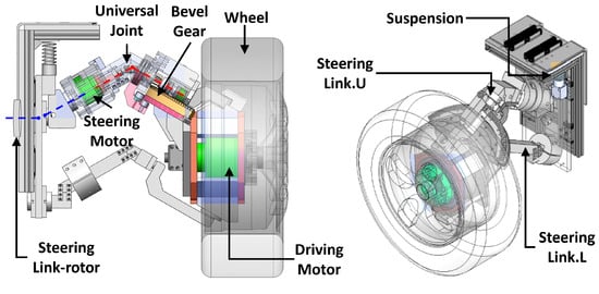
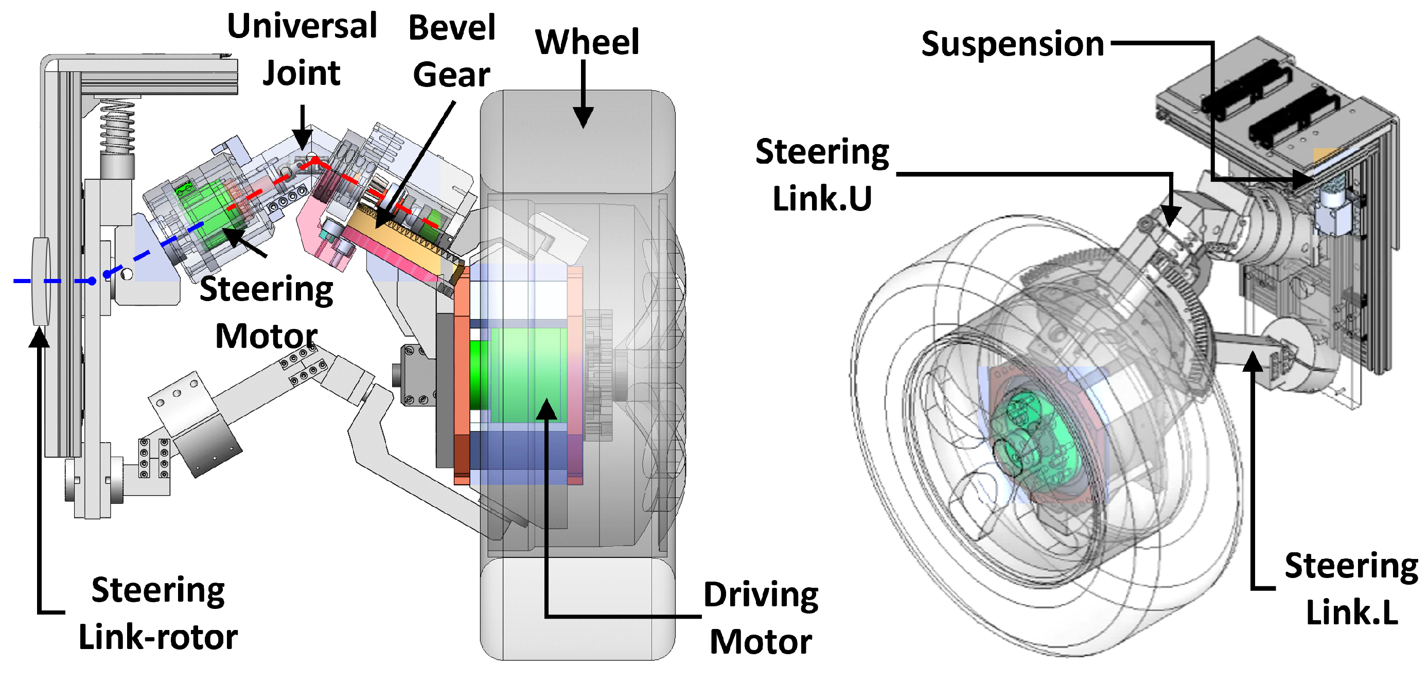
The SDS module integrates a hollow-shaft in-wheel drive motor, a steering motor embedded in the steering link, and a suspension element entirely within the wheel envelope. A single actuator drives both a bevel-gear path and a steering-link tilt path, yielding wheel steering through the dual-path relation subject to the synchronization constraint [1]. Figure 1 reproduces the module layout used in the present platform; the reader is referred to [1] for the full mechanism analysis.
Figure 1.
Exploded view of the Steering–Drive–Suspension (SDS) integrated module showing the in-wheel drive motor, the steering motor housed within the steering link, the bevel-gear power-transmission path, the universal joint, and the suspension element. The dual-path relation enables wide-angle wheel steering within a compact envelope. Adapted from [1].
2.2. Two-Wheel Unit Module
Two SDS modules mounted on a common axle constitute a 2-wheel unit module, the smallest functional building block of our platform. The payload column rests above the axle so the unit behaves as an inverted pendulum that must actively balance in the pitch direction. Yaw motion is produced by differential drive between the left and right SDS units; lateral mobility, when needed, exploits the steering capability of each SDS. This “2WD = unit module” perspective is the central design choice of this paper and contrasts with prior SDS studies [1,30] that treated the 4-wheel platform as primary.
2.3. Reconfiguration Concept: 2WD ↔ 4WD
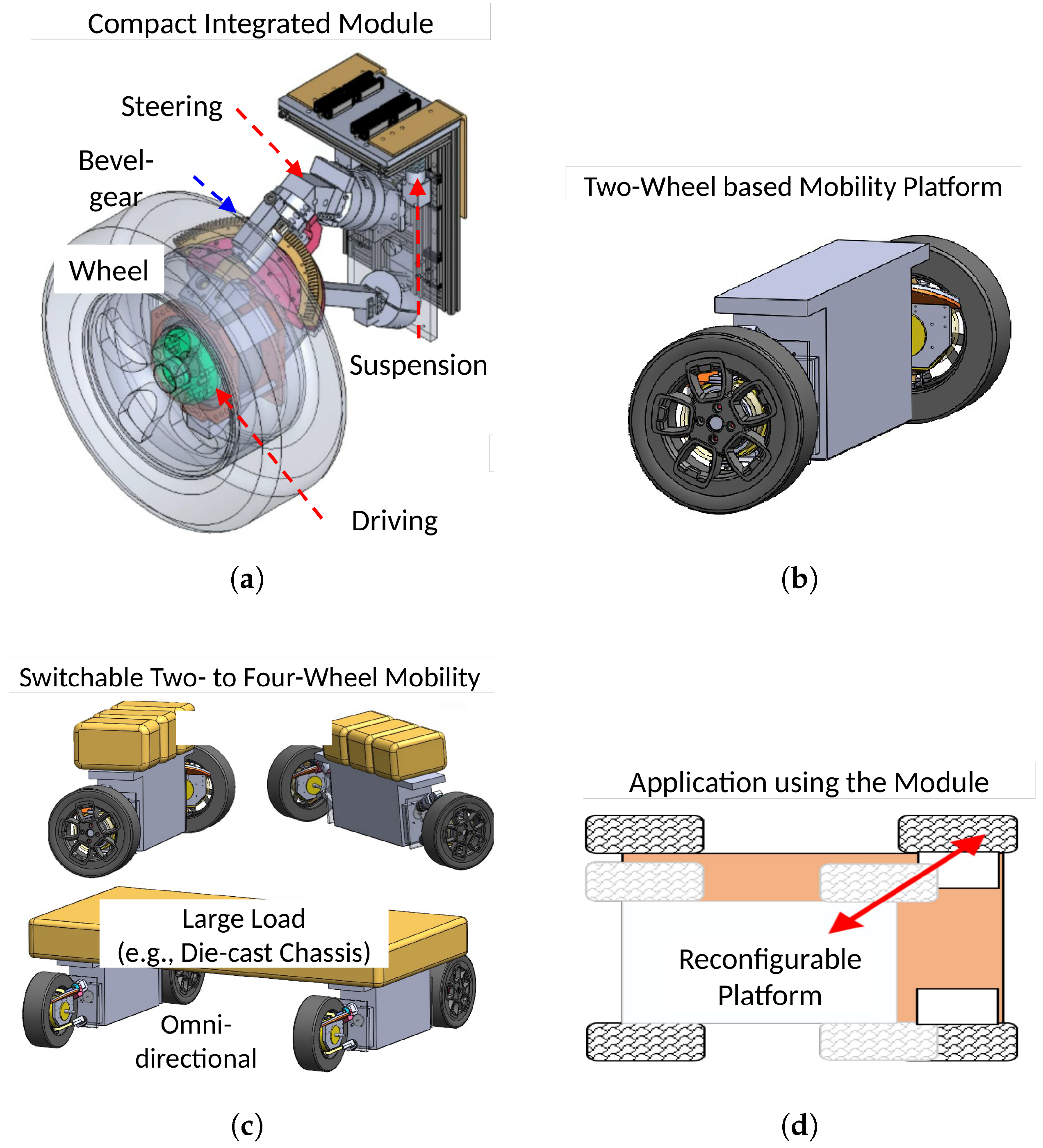
Three operational configurations cover the design envelope (Figure 2):
- Configuration A: a single 2WD unit transports a small payload (≤50 kg) using inverted-pendulum balance.
- Configuration B: two 2WD units, mechanically coupled along the longitudinal direction by a rigid chassis, form a 4WD platform suited to mid-size payloads (≤200 kg). The wheelbase is fixed by the coupling chassis.
- Configuration C: two 2WD units operate as semi-independent agents that jointly carry a large or oversized payload (up to ∼500 kg, e.g., automotive die-cast bodies) without a rigid chassis between them. The payload itself acts as a soft mechanical link, with effective separation determined by payload geometry; in general .
Figure 2.
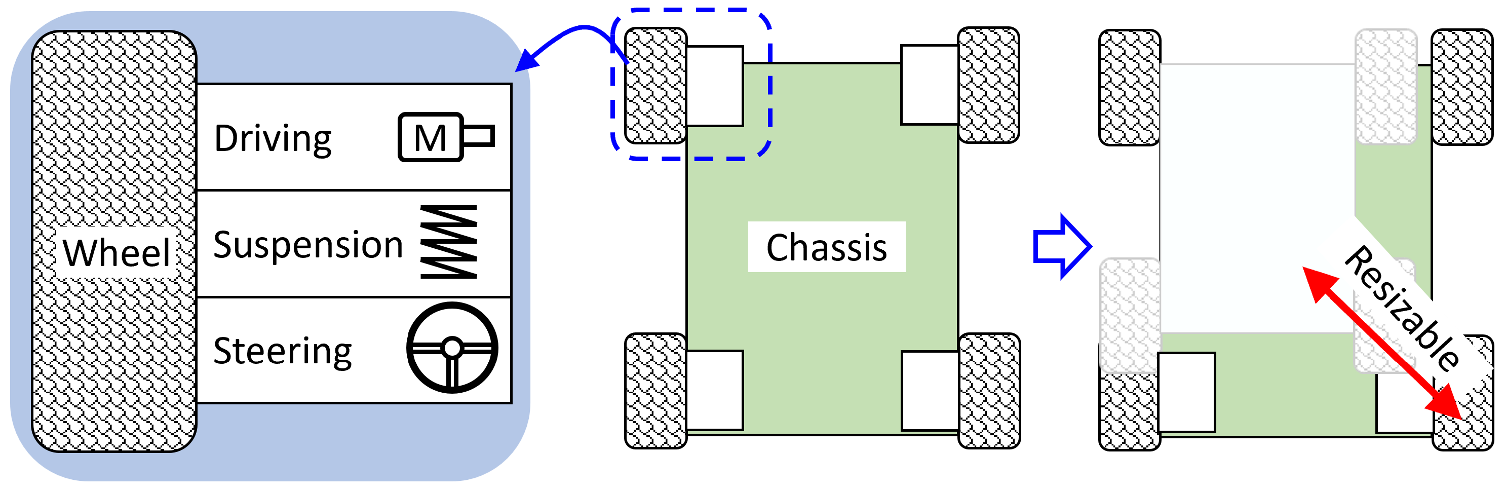
Reconfiguration philosophy of the SDS-based platform: (a) the compact SDS integrated module with steering, bevel-gear transmission, in-wheel drive, and suspension consolidated inside the wheel envelope; (b) a self-balancing two-wheel mobility unit assembled from two SDS modules; (c) switchable two- to four-wheel operation, including omni-directional transport of large loads (e.g., die-cast chassis); (d) the reconfigurable platform concept, in which wheelbase and track are adapted to the payload.
2.4. Driving Modes
Independent steering of all four wheels, enabled by the SDS envelope in Configurations B and C, supports three driving modes: Forward (front steered, rear neutral), Diagonal/Crab (all four wheels steered identically, vehicle translates without yaw), and Ackermann/4WS (front and rear steered with opposing sign for tighter turning). These modes are exploited in Section 4.4 to compare relocation efficiency.
3. Modeling and Control
This section develops the dynamic models for the three configurations and designs the corresponding controllers. The reconfiguration time scale (seconds) is much longer than the pitch and yaw mode time scales (tens to hundreds of milliseconds), so each configuration is treated as a frozen LTI plant; that is, the framework is piecewise-LTI, and no Linear-Parameter-Varying or time-varying treatment is introduced. The controllers comprise an LQR balance loop, a PI velocity loop with virtual-Ackermann lateral allocation, and an admittance-based cooperative loop.
3.1. Notation
Throughout this section, denote the longitudinal cart position and velocity (Configuration A); the pitch angle and rate of the payload column; the yaw angle and rate; the chassis sideslip; the front and rear steering angles; the common-mode and differential-mode wheel torques; r the wheel radius; the track width; the cart and payload masses (Conf. A); M the total vehicle mass (Conf. B/C); the height of the payload centre of mass (CoM) above the axle ( m); the CoM-to-front-axle and CoM-to-rear-axle distances; the wheelbase, with in Configuration B and in Configuration C; the payload and vehicle yaw inertias; the per-axle cornering stiffnesses; V the longitudinal speed; A Abe’s stability factor; K the LQR feedback gain; the LQR weight matrices; the virtual mass, damping, and stiffness of the admittance dynamics; and the force measured at the rear-platform-payload interface.
3.2. Modeling
3.2.1. 2WD Inverted-Pendulum Dynamics (Configuration A)
Configuration A is modelled as a self-balancing 2-wheel cart with a rigid payload column. The payload mass is lumped at height above the wheel centre, and the column-chassis joint is approximated as a frictionless hinge (small compliances are absorbed into and ). With x taken positive forward and positive when the column tips forward, applying Newton-Euler about the wheel centre yields the longitudinal force balance
the column moment balance about the hinge
and the yaw equation about the body vertical axis
Equation (3) is decoupled from (1), (2) at first order in , a fact exploited in Section 3.2.3. Linearising (1), (2) about , and dropping the term, solving for gives
where . With and input , the state-space form is
with , , , . The characteristic polynomial of is , yielding one positive real eigenvalue , the well-known cart-pole open-loop instability. The controllability matrix determinant, derived in Appendix A, reduces to
so and the longitudinal-pitch subsystem is fully controllable from the single input , justifying the single-input LQR design in Section 3.3.1.
3.2.2. Planar 2-DOF Bicycle Model (Configurations B and C)
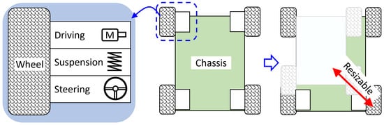
In Configurations B and C the platform stays upright; pitch is no longer an active state. Lateral dynamics are modelled by Abe’s classical 2-DOF planar bicycle [13] (Figure 3), in which the left and right front (resp. rear) tyres are lumped into a single equivalent steered (resp. trailing) tyre, and the longitudinal speed V is held constant by the PI loop of Section 3.3.2. The lateral force balance and yaw moment balance about the CoM are
with linear-region tyre forces and slip angles , . Substituting into Equation (7) yields the LTI state-space
Figure 3.
Schematic of the SDS-based mobility platform. The integrated module (left) consolidates drive, suspension, and steering functionality and is mounted at the corners of a chassis (right) whose wheelbase and track can be reconfigured between Configurations B and C; this layout provides the geometric basis for the planar bicycle model derived in Section 3.2.2.
The steady-state yaw-rate gain follows by setting :
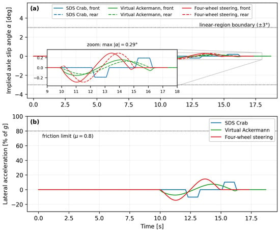
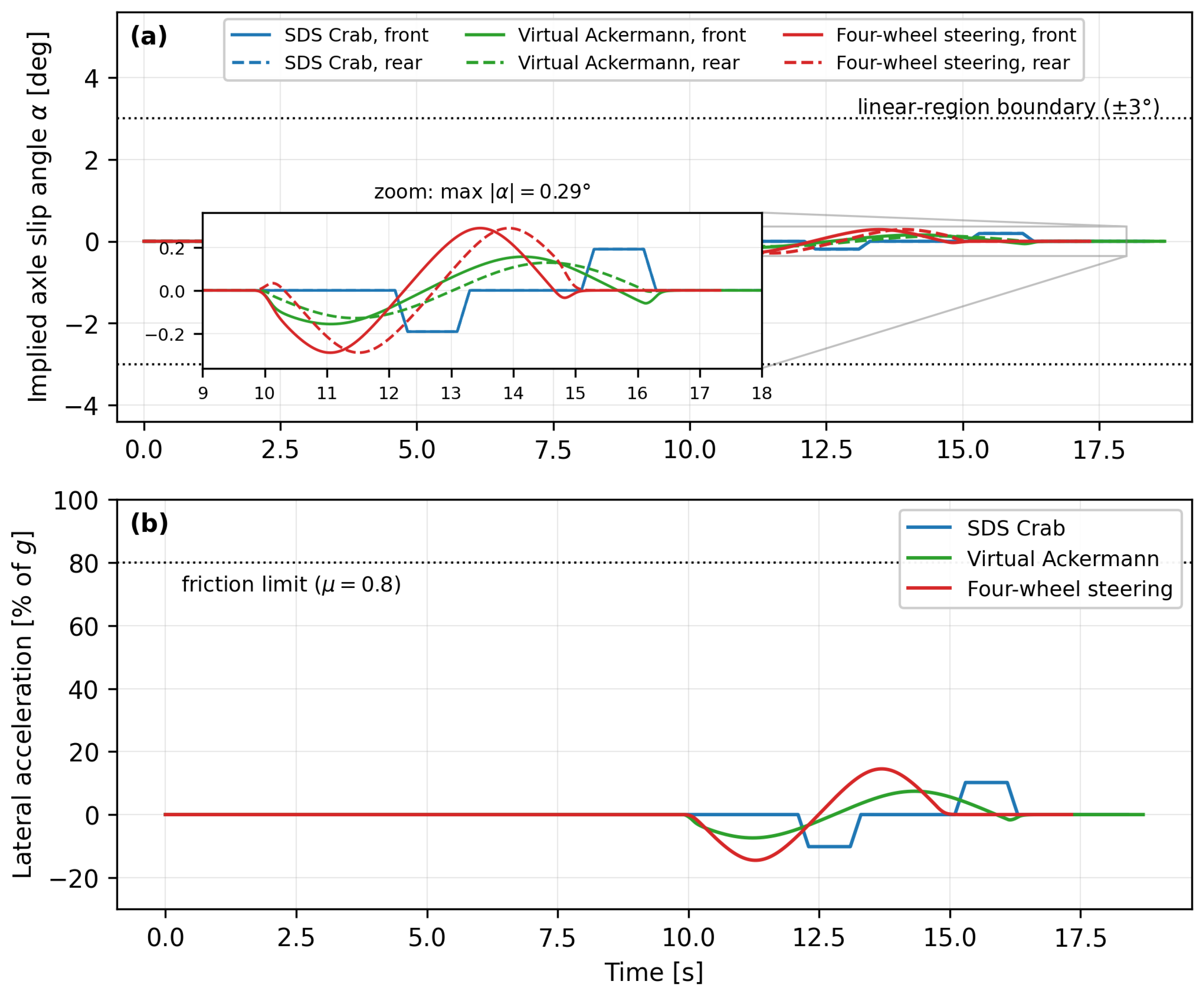
where and A is Abe’s stability factor; corresponds to understeer and to oversteer. The platform is intentionally designed with and , yielding and a mildly understeer character that is verified in Section 4. Equations (8)–(10) are structurally identical for Configurations B and C; only the wheelbase differs ( vs. ). The validity of the constant-cornering-stiffness, small-angle assumptions underlying Equation (8) for the manoeuvres simulated in this paper, including the steering commands of the Crab mode, is quantified in Section 4.4: because the platform operates at ≤1 m/s, the largest implied axle slip angle across all three driving modes is , an order of magnitude inside the linear tyre region [15,16].
3.2.3. Pitch–Yaw Decoupling (Configuration A)
At first order in , the projection holds and the yaw inertia is unaffected by pitch motion to . Consequently Equation (3) contains no first-order terms, and Equation (4) contains no first-order terms (only centrifugal coupling, negligible in normal operation). This allows the LQR balance loop and the yaw PD loop to be designed independently.
3.3. Control
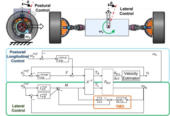
The control design is organised into three configuration-specific loops, integrated within the hierarchical architecture summarised in Figure 4.
Figure 4.
Hierarchical control architecture combining postural balance (LQR), lateral driving (virtual Ackermann), and yaw-moment observer (YMO) feedforward.
3.3.1. LQR Balance Control (Configuration A)
Equation (5) together with the controllability result Equation (6) ensures that an infinite-horizon Linear-Quadratic Regulator stabilises the longitudinal-pitch subsystem [31]. The state feedback minimises
with optimal gain
where solves the continuous algebraic Riccati equation
Weight Selection (Bryson’s Rule of Thumb)
Pitch stabilisation matters far more than fine cart-position tracking. Following Bryson’s rule [32], the diagonal entries of Q are inverse squares of the maximum permissible RMS deviations: m, m/s, rad, rad/s, giving
The numerical K matrix and closed-loop pole locations obtained by substituting the platform parameters of Section 4.1 into Equations (12) and (13) are reported alongside the simulation results in Section 4.2. The classical robustness result for SISO LQR with scalar R and positive-definite Q [31] (Ch. 4), namely on the loop transfer function, automatically guarantees an infinite upper gain margin, a 6 dB lower gain margin, and a phase margin .
Yaw Auxiliary Loop
By the decoupling argument of Section 3.2.3, the yaw channel is closed by a PD controller
with bandwidth chosen well below the pitch loop to minimise inter-loop interference.
Pitch Feedforward for Velocity Tracking
During acceleration, the cart must lean slightly forward by . Adding this lean angle to the LQR reference removes the steady-state velocity error during constant-acceleration segments.
3.3.2. Driving Control (Configurations B and C)
In Configurations B and C the upright posture is naturally stable and no LQR balance loop is needed. Instead the driving controller comprises (i) a longitudinal PI velocity loop, (ii) a virtual-Ackermann lateral allocation, and (iii) a Yaw-Moment Observer (YMO) feedforward inherited from [30].
Longitudinal PI Loop
The four-wheel average drive torque tracks the velocity reference :
The gains are tuned for a closed-loop bandwidth of approximately 2 Hz with phase margin . Conditional integration prevents wind-up during torque saturation.
Virtual-Ackermann Lateral Allocation
Given a desired path curvature and turning radius measured to the rear-axle centre, the inner and outer front-wheel steering angles satisfy
Because each SDS module steers independently, Equation (17) is a virtual (software) Ackermann allocation rather than a kingpin-linkage geometry. Configuration C extends this to all four wheels and enforces the four-wheel-steer (4WS) curvature consistency
so that the front and rear allocations remain compatible. The same framework directly expresses the SDS-specific Crab and in-place yaw modes used in Section 4.4.
YMO Feedforward
Slowly varying external yaw disturbances , asymmetric payload, road camber, tyre-pressure imbalance, are estimated by the yaw-moment observer of [30] and added as a feedforward steering correction
where is the lateral-force-to-steer sensitivity derived from Equation (10). The full observer design is given in [30]; in the present paper YMO is treated as a black-box module that improves robustness on the lateral channel.
3.3.3. Impedance-Based Cooperative Control (Configuration C)
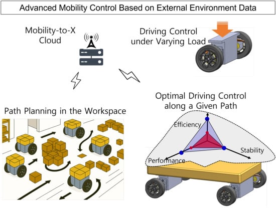
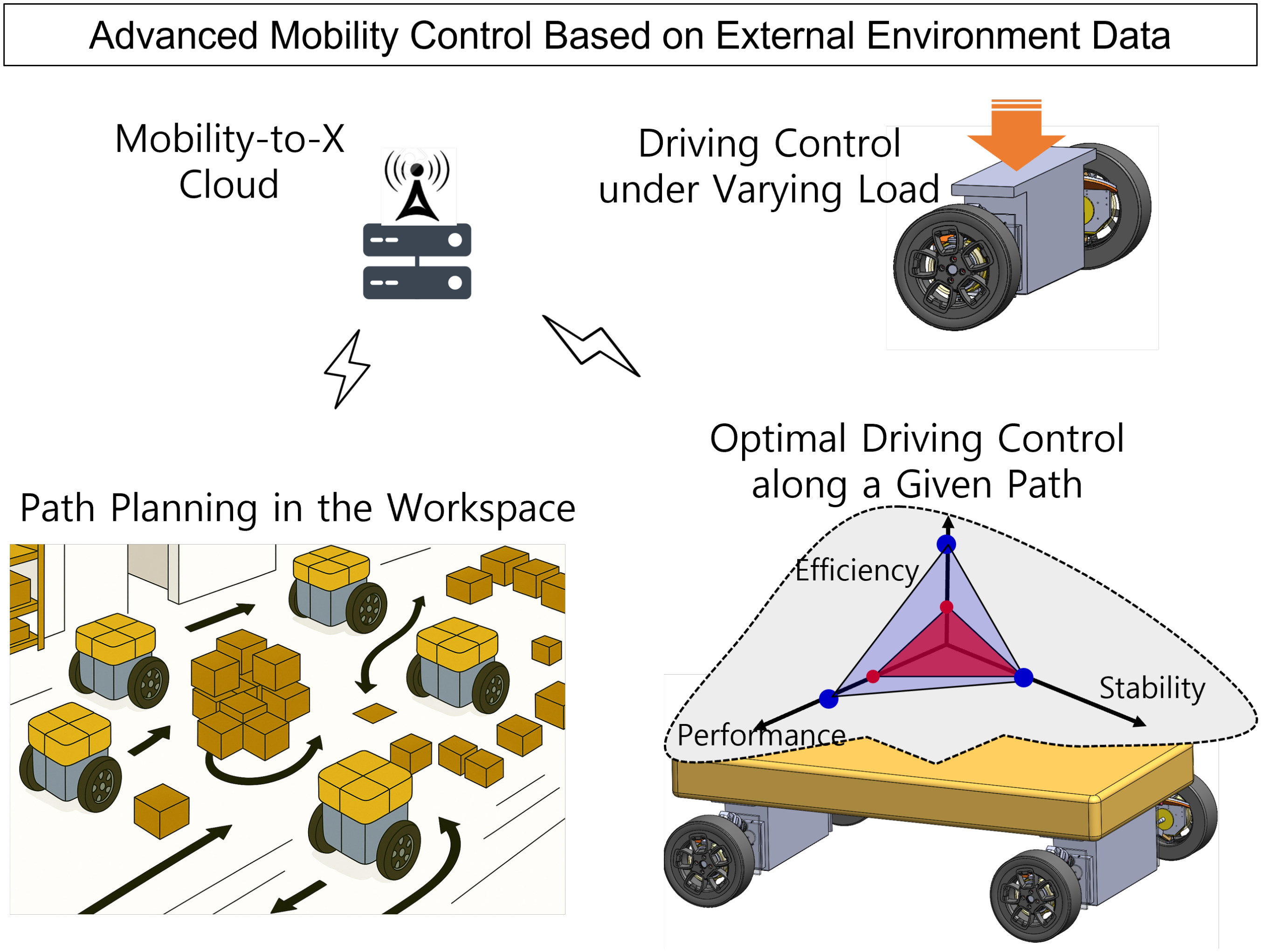
Configuration C couples two 2WD units only through the shared payload, with no rigid chassis between them. The cooperative law is an admittance (force-in, motion-out) controller, deliberately distinguished from impedance (motion-in, force-out) [20]: a force sensor on the rear unit measures , which is fed into a virtual second-order dynamics that produces a velocity correction. Figure 5 situates this cooperative configuration within its cloud-assisted application context.
Figure 5.
Application context for the cooperative configuration. Cloud-assisted Mobility-to-X path planning, i.e., a cloud-robotics framework in the sense of [29] in which a cloud layer provides load-, energy-, and stability-aware trajectory selection for heterogeneous mobility agents across the workspace, provides the mission context motivating the impedance/admittance-based cooperative law of Section 3.3.3 between two SDS-based 2WD units sharing a payload.
Virtual Mass-Spring-Damper
Let denote the nominal payload-imposed separation and the longitudinal separation error. The rear unit is commanded to behave as the virtual second-order system
At each control step, Equation (20) is integrated with the measured to update , and the rear-unit velocity command is
When (the payload pulls the rear unit forward), decreases, increasing and re-closing the gap.
Admittance Transfer Function
Taking the Laplace transform of Equation (20),
The simulator parameters give rad/s (≈0.20 Hz) and .
Tuning Rationale
The conventional admittance design region targets fast response. Here we deliberately choose an over-damped regime () to avoid exciting the slosh mode of the heavy payload and to suppress sensor-noise and road-input feed-through at higher frequencies; this is consistent with the application priority of smooth, non-oscillatory transport. The trade-off is that the response time to external disturbances is roughly twice that of a critically damped design, which is acceptable for steady-state cooperative transport of a 100 kg-class payload.
Cascade Stability
Closed-loop stability of the cooperative system is established constructively: (i) each 2WD unit’s inner LQR pitch loop is globally exponentially stable with bandwidth Hz; (ii) the admittance ODE Equation (20) has Hurwitz characteristic polynomial for any positive and is therefore BIBO-stable; (iii) the two time scales (5 Hz vs. 0.2 Hz) are separated by more than one decade, so a standard singular-perturbation argument guarantees the cascade is stable.
3.4. Control Architecture Summary
The three configuration-specific controllers are integrated within a three-layer hierarchy. A high-level mode selector chooses between Configurations A, B, and C based on payload mass and mission type, and applies a s linear blend during transitions to smooth command discontinuities. The mid-level controller is configuration-specific: Configuration A activates the LQR balance loop, the yaw PD loop Equation (15), and the pitch feedforward; Configuration B activates the longitudinal PI loop Equation (16), the front-only virtual-Ackermann allocation Equation (17), and the YMO feedforward Equation (19); Configuration C activates the longitudinal PI loop, the four-wheel-steer allocation Equations (17) and (18), the YMO feedforward, and the admittance cooperative law Equations (20) and (21). The low-level layer comprises the per-module SDS in-wheel torque servo and steering servo, whose hardware validation has been reported in [1] and is treated here as a black box. Modularity is the central design property: a configuration change is realised in the high-level selector alone, the mid-level swaps automatically, and the low-level SDS servos are unaffected.
4. Simulation and Results
4.1. Simulation Setup
All scenarios are simulated in Python 3.12 using fixed-step integration (1–3 ms, RK4 for the inverted-pendulum dynamics) with the control law evaluated at every integration step; the robustness scenario S1-R of Section 4.3 additionally injects measurement noise sampled and held on a 3 ms grid. The platform parameters listed in Table 1 are taken from the JMR prototype [1] where available, with mass and inertia values for the payload and chassis estimated from CAD when not directly published. Three scenarios, one per configuration, exercise the framework end-to-end.
Table 1.
Platform parameters used in the simulation. Values marked † are taken from [1]; values marked ‡ are CAD/engineering estimates.
4.2. Scenario S1: 2WD Balance and Tracking (Configuration A)
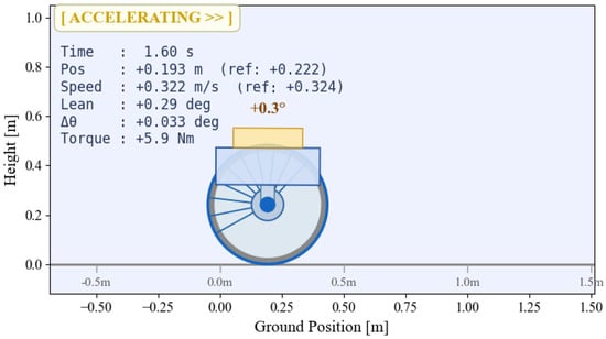
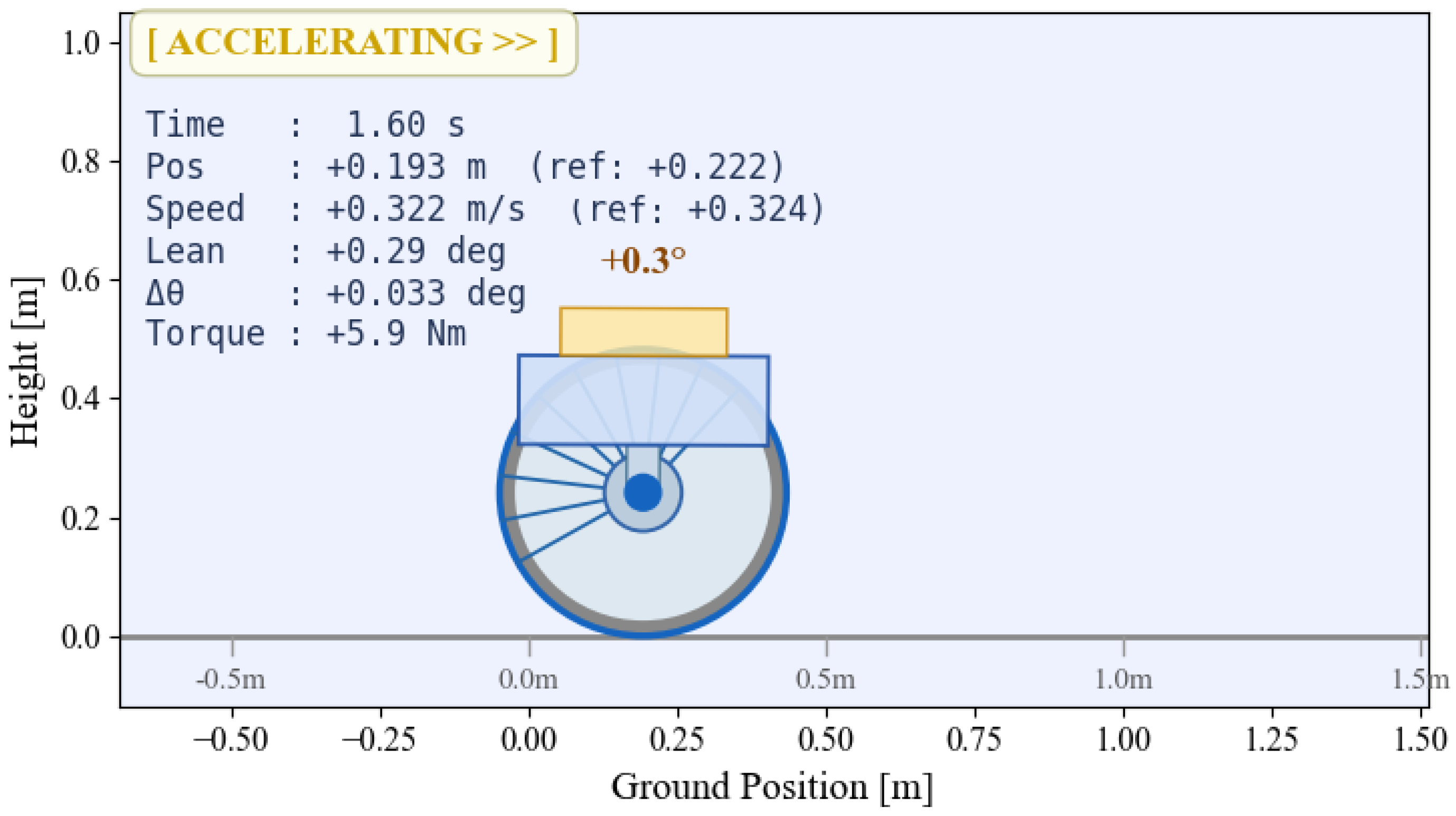
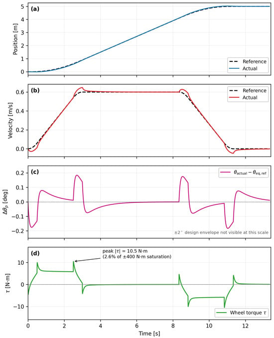
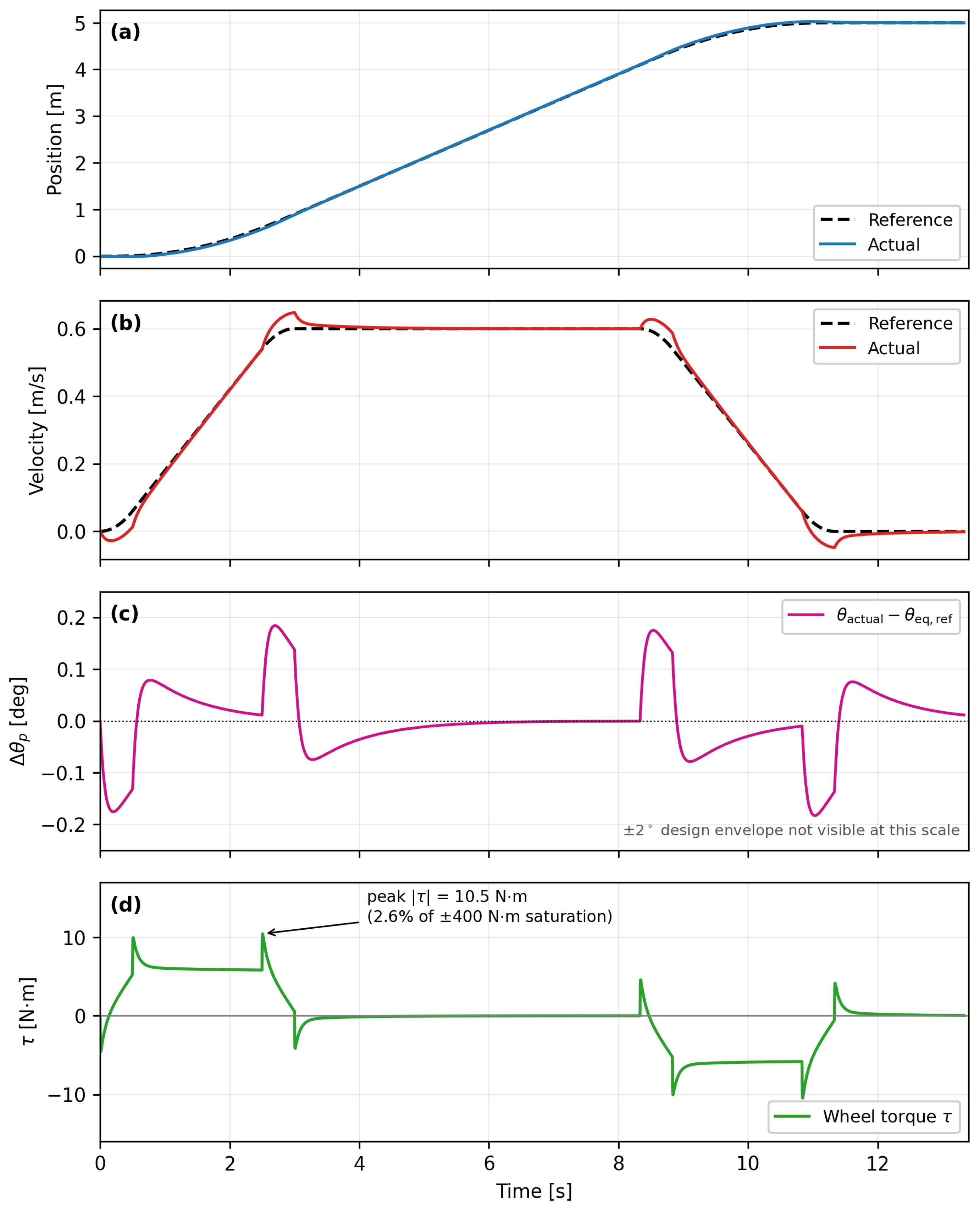
A single 2WD unit follows a 5 m longitudinal reference with a jerk-limited trapezoidal velocity profile (peak m/s, 3 s acceleration and deceleration ramps with s jerk-limited corners) over a s horizon. The simulation environment is illustrated in Figure 6, and the resulting time histories are summarised in Figure 7: position, velocity, pitch deviation measured relative to the time-varying equilibrium , which already contains the acceleration-dependent lean, and wheel torque . Position tracking is sub-centimetre during cruise, with a worst-case transient error of cm during the ramps. The pitch deviation stays within , well inside the design envelope. The wheel-torque demand peaks at N·m, i.e., of the N·m actuator saturation of Table 1; Figure 7d therefore uses a N·m scale rather than plotting the distant saturation bound. The wide margin is intentional: the saturation budget is reserved for payload variation, slope climbing, and disturbance rejection, and the robustness scenario of Section 4.3 shows that an 80 N external push raises the instantaneous torque demand by roughly an order of magnitude above the nominal level. These results confirm that the LQR balance gain plus pitch feedforward jointly suffice to maintain stability and tracking under the imposed velocity profile.
Figure 6.
Scenario S1 simulation environment: a single 2WD SDS unit with payload column tracking a longitudinal reference under inverted-pendulum balance.
Figure 7.
Scenario S1 results: 2WD inverted-pendulum balance and longitudinal tracking. From top: (a) position, (b) velocity, (c) pitch deviation relative to the time-varying equilibrium ( peak; the design envelope lies far outside the plotted range), and (d) wheel torque , whose N·m peak corresponds to of the N·m actuator saturation of Table 1. In panels (c,d) the dashed line denotes the reference and the solid line the simulated response.
4.3. Scenario S1-R: Robustness to Measurement Noise, Mass Variation, and External Disturbance
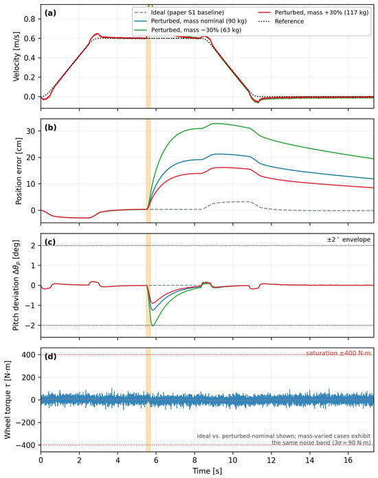
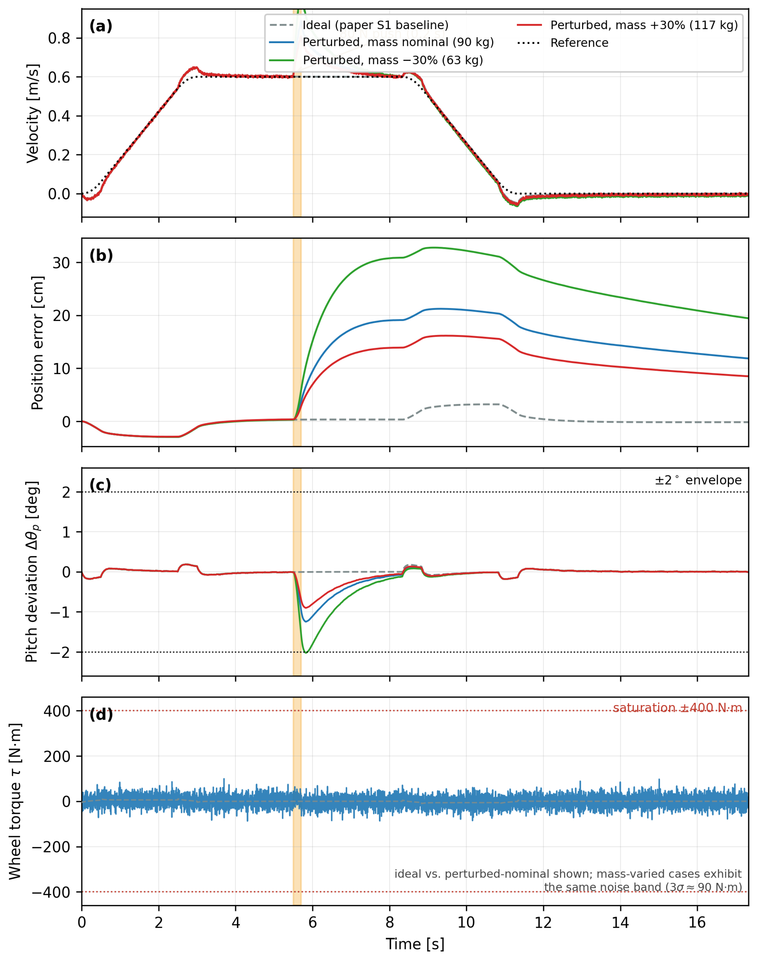
The nominal results of Scenario S1 are obtained under idealised conditions. To quantify how the same controller behaves under realistic non-idealities, Scenario S1-R repeats S1 with the unchanged nominal LQR and feedforward design (computed for the 90 kg plant) while simultaneously injecting: (i) measurement noise representative of a complementary-filtered IMU and encoder differentiation (, /s, mm, mm/s, sampled and held on the 3 ms grid); (ii) a total-mass variation of (63–117 kg) unknown to the controller; and (iii) an 80 N horizontal push applied at the payload centre of mass for s during cruise. Figure 8 compares the ideal baseline with the three perturbed cases. Measurement noise alone degrades cruise tracking by less than 1 cm and produces a zero-mean torque band of N·m, still well within the N·m saturation. The push produces a transient position error of up to 33 cm (for the plant) that decays through the intentionally soft position mode (slowest closed-loop pole at rad/s), while balance itself recovers within about s; the pitch deviation remains inside the envelope for the nominal and plants and momentarily reaches for the plant, marking the practical edge of the unmodified design. Communication delay, which is relevant to the force-coupled Configuration C, is tolerated by design: the admittance loop bandwidth of Hz (Section 3.3.3) is orders of magnitude below typical intra-platform communication rates, so delays of tens of milliseconds shift the loop phase at crossover by well under one degree. Wheel slip is addressed by the friction-utilisation analysis of Section 4.4, which shows that at most of the available tyre friction is used in any simulated manoeuvre.
Figure 8.
Scenario S1-R results: robustness of the unchanged S1 controller. (a) velocity; (b) position error; (c) pitch deviation against the envelope; (d) wheel torque (ideal vs. perturbed-nominal; the mass-varied cases exhibit the same N·m noise band). The shaded band marks the 80 N, s push applied during cruise.
4.4. Scenario S2: Forward and Lateral Relocation in Three Modes (Configuration B)
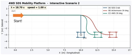
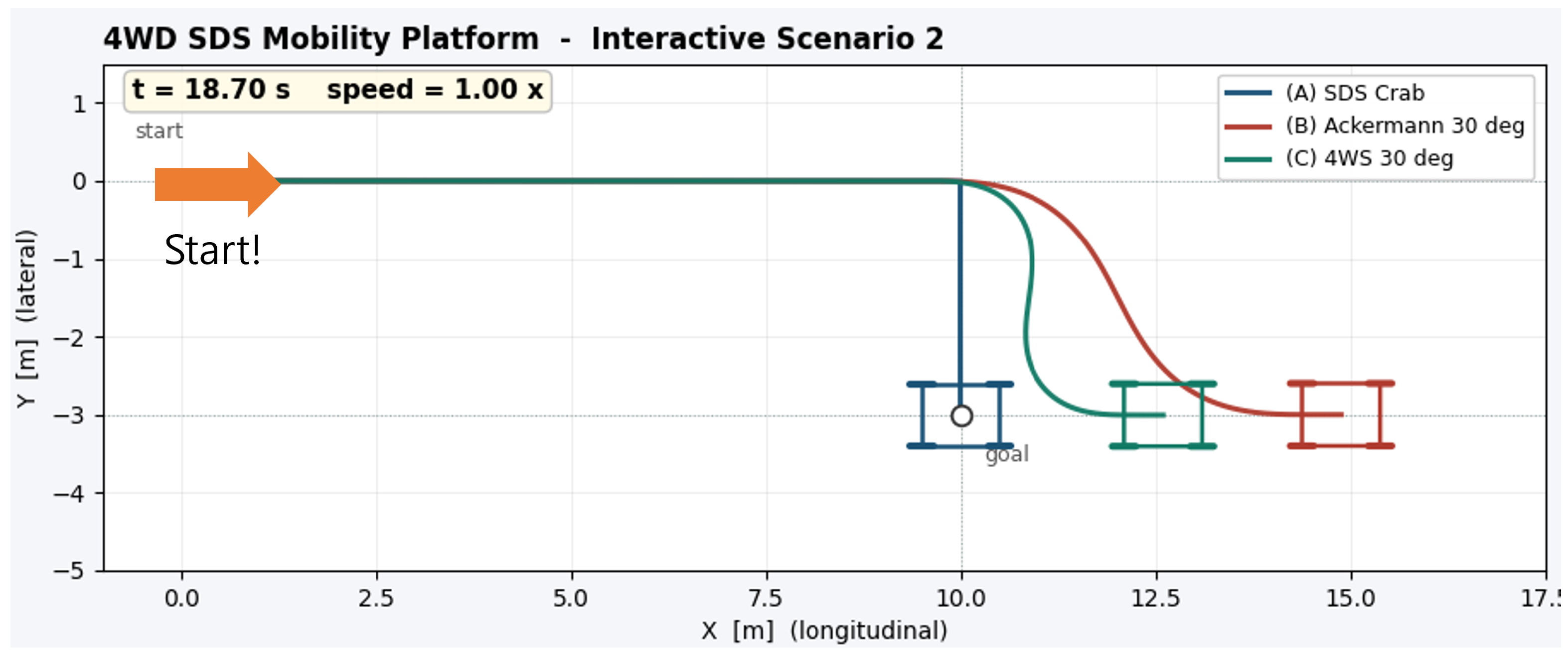
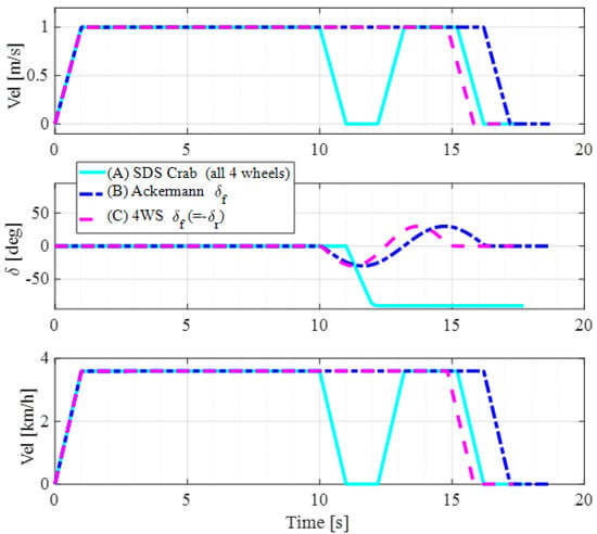
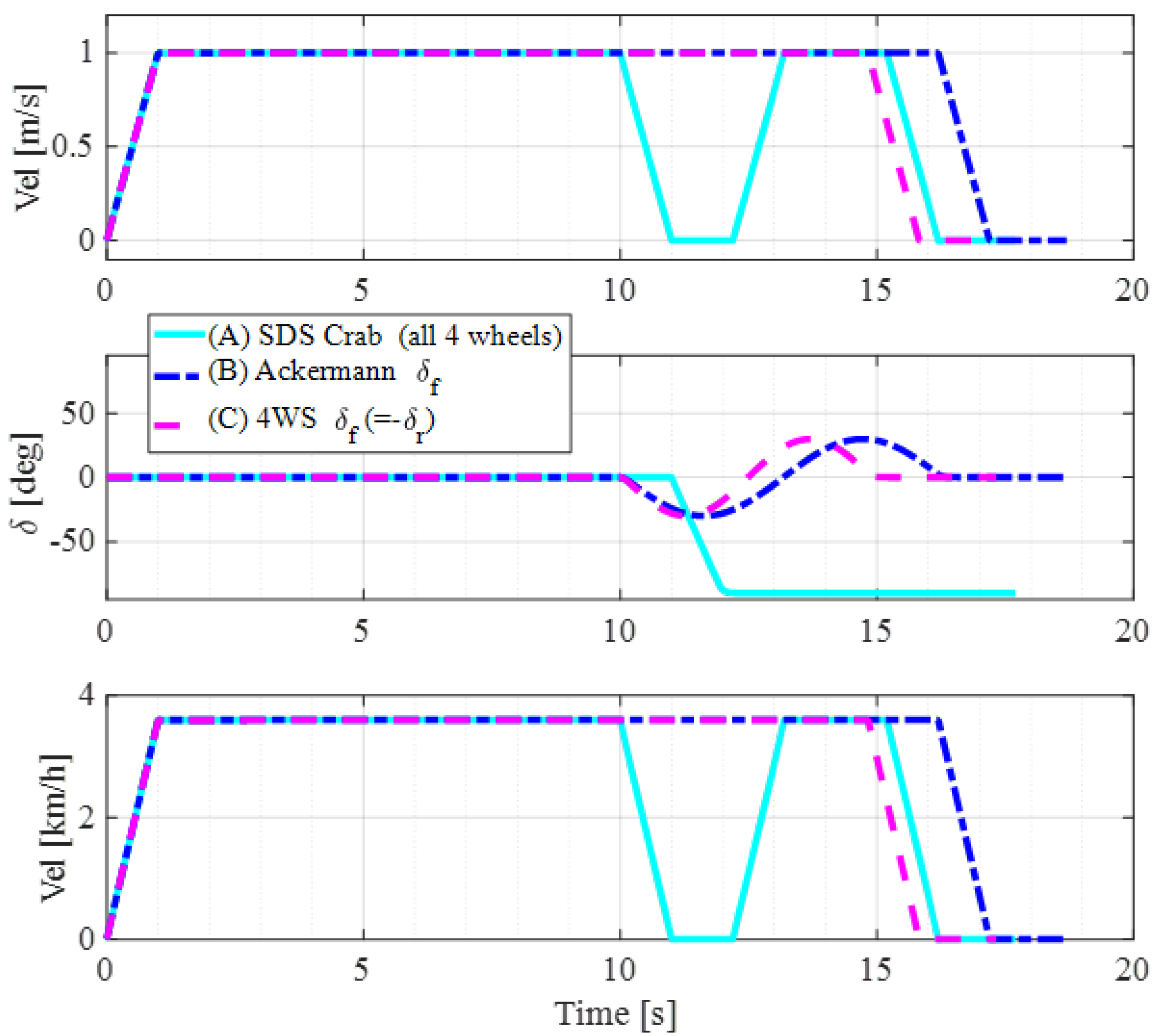
A common forward 10 m and lateral 3 m relocation manoeuvre is performed by the same 4WD platform under three distinct steering modes: (A) SDS Crab with , (B) front-only Ackermann with , and (C) four-wheel steering with and . The simulation environment is illustrated in Figure 9. Figure 10 contrasts the three modes across seven panels: trajectory, lateral displacement, chassis forward speed, steering-angle tracking, wheel drive torque, chassis yaw, and a performance bar (path length, time, lateral error). The SDS Crab mode (A) achieves the relocation with negligible yaw rotation, leveraging the SDS envelope to shift the entire chassis sideways without re-orienting it. The Ackermann (B) and 4WS (C) modes both require large yaw excursions (up to ∼) to deflect the velocity vector, increasing path length and travel time. The proposed virtual-Ackermann allocation Equations (17) and (18) is the common interface that selects between modes via a single curvature reference.
Figure 9.
Scenario S2 simulation environment: 4WD SDS platform performing a forward 10 m and lateral 3 m relocation under three candidate steering modes (SDS Crab, Ackermann, 4WS).
Figure 10.
Scenario S2 results: forward 10 m and lateral 3 m relocation in three driving modes (SDS Crab, Ackermann, 4WS). The SDS Crab mode benefits from the SDS envelope and reaches the goal without yaw re-orientation, whereas Ackermann and 4WS sweep large yaw angles.
Tyre-Model Validity
The planar model of Section 3.2.2 assumes constant cornering stiffness and small slip angles, and a natural concern is whether these assumptions hold for manoeuvres that command steering angles up to . Large steering angles, however, do not imply large tyre-slip angles: in the Crab mode all wheels remain aligned with the velocity vector, so the tyres operate near zero side-slip by construction, and the kinematic chassis re-orientation in the Ackermann and 4WS modes occurs at ≤1 m/s. To quantify this, the axle lateral forces required to execute the recorded S2 trajectories were reconstructed from the worst-case inertia ( kg, kg·m2) and converted into implied slip angles . Figure 11 shows the result: the largest implied slip angle is (4WS), with for Crab and for Ackermann, an order of magnitude inside the region over which the Magic Formula [15,16] deviates from its linear approximation by only a few percent for the stiffness and load values of Table 1. The peak lateral acceleration is , i.e., at most of the available friction (), so neither force saturation nor combined-slip effects are approached. The constant-stiffness linear model therefore introduces negligible error in the regimes studied here; a nonlinear tyre model becomes necessary only at substantially higher speeds or friction utilisation, which lies outside the operating envelope of the logistics application targeted by this platform.
Figure 11.
Tyre-model validity analysis for Scenario S2. (a) Implied axle slip angles for the three driving modes, with the linear-region boundary and a zoomed inset (peak ); (b) lateral acceleration as a percentage of g, compared with the friction limit. All modes remain an order of magnitude inside the linear tyre region, justifying the constant-cornering-stiffness bicycle model for the simulated manoeuvres.
4.5. Scenario S3: Cooperative Heavy-Load Transport (Configuration C)
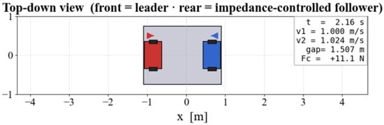
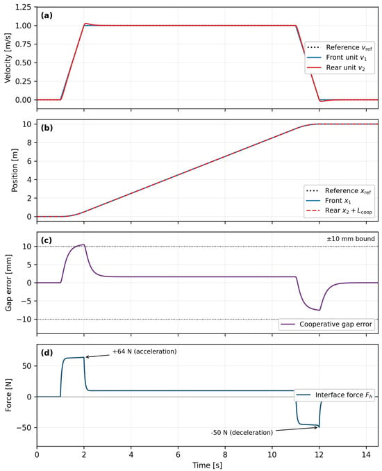
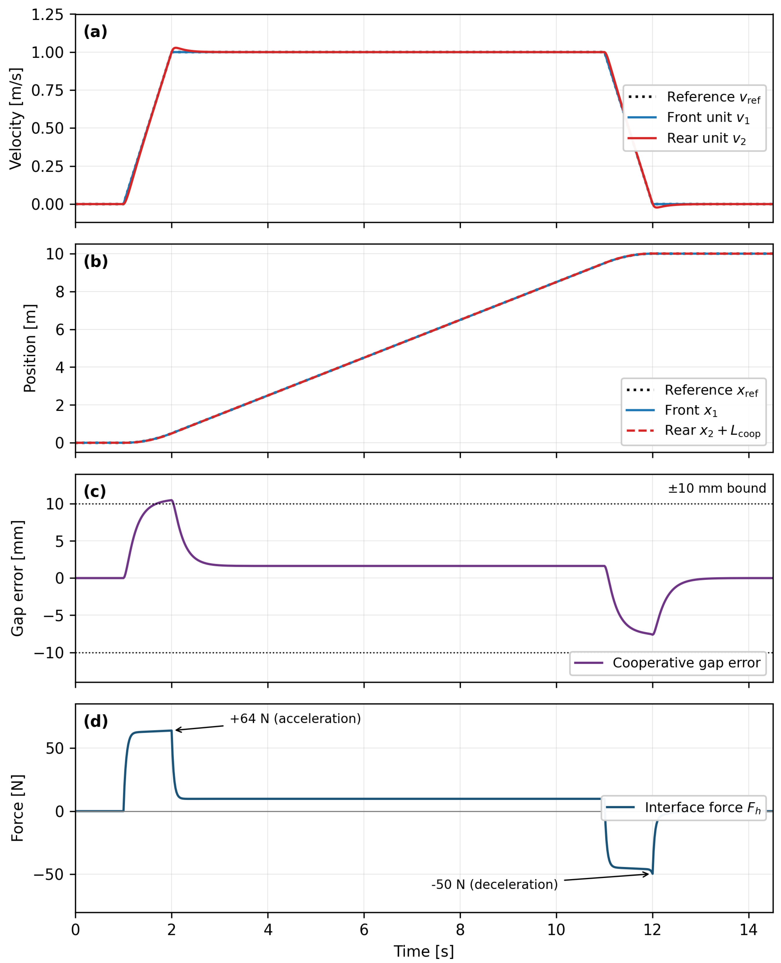
Two 2WD units jointly transport a 100 kg, m steel plate over 10 m at 1 m/s. The simulation environment is illustrated in Figure 12. The front unit runs the velocity-control loop Equation (16); the rear unit runs the admittance law Equations (20) and (21) with the parameters of Table 1. Figure 13 shows the platform velocities, the front and rear positions (with the rear shifted by for direct comparison), the cooperative gap error plotted on a millimetre scale, and the payload-interface force . During acceleration the interface force plateaus at N as the plate momentarily resists the front unit; during deceleration it reverses to N as the plate brakes against the rear unit. The gap error remains within mm over the whole manoeuvre and within mm during cruise. The over-damped admittance design () prevents oscillation despite the substantial payload inertia, validating the design choice of Section 3.3.3.
Figure 12.
Scenario S3 simulation environment: two SDS-based 2WD units jointly transporting a 100 kg, m steel plate via impedance-based cooperative coupling. The front unit is drawn in blue and the rear unit in red.
Figure 13.
Scenario S3 results: cooperative impedance-based transport of a 100 kg, m steel plate by two 2WD units over 10 m at 1 m/s. From top: (a) platform velocities; (b) positions (rear shifted by ); (c) cooperative gap error on a millimetre scale, bounded by mm; (d) payload-interface force with N acceleration and N deceleration plateaus.
4.6. Discussion
Across the three scenarios the same SDS hardware is reconfigured to three distinct missions, each with quantifiably satisfactory tracking and stability. Three observations support the central claim of the paper: (i) the 2WD-as-unit-module philosophy is feasible, a compact 2WD platform self-balances and tracks paths at sub-centimetre accuracy with wheel-torque margins to spare; (ii) the same platform, when rigidly coupled, performs forward and lateral relocations with three distinct steering modes, and the SDS-specific Crab mode delivers a measurably shorter path length and time at the cost of higher peak steering angle, a trade-off only available because of the envelope; (iii) the impedance-coupled cooperative configuration handles a heavy oversized payload without rigid synchronisation, and the over-damped admittance design absorbs payload-induced disturbances without sloshing. The principal limitation of the present study is the absence of platform-level experimental validation, and the reason is stated explicitly: the SDS module hardware (steering envelope, in-wheel drive, and suspension kinematics) was fabricated and experimentally characterised in our previous study [1], whereas the reconfigurable platform prototype integrating two 2WD units with a payload-interface force sensor is currently under fabrication within the funding programme supporting this work, and no platform-level test article existed at the time of writing. The present paper is therefore deliberately scoped as the modelling, control-design, and simulation stage of a staged research programme. To partially compensate within the simulation domain, the robustness scenario S1-R quantifies the effect of measurement noise, mass variation, and impulsive disturbances on the unchanged nominal controller, and the tyre-model analysis of Section 4.4 bounds the friction utilisation below , supporting the no-slip assumption. Payload sloshing and ground-friction variability remain idealised and are flagged for the hardware campaign outlined in Section 5.
5. Conclusions
This paper presented an SDS-based reconfigurable mobility platform in which a 2-wheel inverted-pendulum unit module serves as the operational primitive, two such units may be rigidly coupled to form a 4WD vehicle, and two further units may be cooperatively coupled through a shared payload using an admittance control law. The 2WD inverted-pendulum dynamics, the planar 2-DOF bicycle dynamics, an LQR balance controller with full controllability proof and classical robustness margins, a virtual-Ackermann driving controller, and an over-damped admittance cooperative controller were unified within a hierarchical three-layer architecture. Three Python simulation scenarios, 2WD balance tracking, forward and lateral relocation in three driving modes, and cooperative heavy-load transport, validated each configuration against its respective tracking and stability targets. Future work will focus on (i) staged experimental validation, i.e., module-level hardware-in-the-loop tests reusing the experimental rig of [1], single-unit balance and tracking experiments on the 2WD platform prototype currently under fabrication, and finally force-coupled cooperative transport trials; (ii) closed-loop integration with the XR digital-twin environment of [30]; (iii) on-line tuning of the admittance gains under payload-mass uncertainty; and (iv) extension to cooperative units transporting irregularly shaped or articulated payloads.
Funding
This work was supported by the Regional Innovation System & Education (RISE) program through the Daegu RISE Center, funded by the Ministry of Education (MOE) and the Daegu Metropolitan City, Republic of Korea (grant number 2025-RISE-03-002).
Data Availability Statement
The simulation code that supports the findings of this study is available from the corresponding author upon reasonable request.
Acknowledgments
The author thanks Kwak, for providing access to the physical SDS platform, which will support the development of this study into future research.
Conflicts of Interest
The author declares no conflict of interest.
Appendix A. Controllability of the Cart-Pole State-Space
The controllability matrix of Equation (5) is . Direct evaluation gives
After two row swaps and one column swap, takes the block-diagonal form with , so . Substituting the definitions of and using the identity yields , hence .
References
- Choi, J.; Jung, H. Design and Evaluation of a Compact Steering-Driving-Suspension Module with Wide-Angle Steering for Reconfigurable Mobility Platforms. Asme J. Mech. Robot. 2026, 18, 034501. [Google Scholar] [CrossRef] [Scilit]
- Wang, Y.; Zhao, Y.; Zhang, M.; Liu, Y.; Lin, C.; Wang, Z. Research on Hierarchical Motion Control of Corner Module Configuration Intelligent Electric Vehicle. Chin. J. Mech. Eng. 2025, 38, 23. [Google Scholar] [CrossRef] [Scilit]
- Tian, Y.; Yao, Q.; Hang, P.; Wang, S. Towards Autonomous Driving: Review and Perspectives on Configuration and Control of Four-Wheel Independent Drive/Steering Electric Vehicles. Actuators 2021, 10, 184. [Google Scholar] [CrossRef] [Scilit]
- Wang, Y.; Yu, H.; Xie, H.; Zhao, Y. In-Wheel Motor Drive Systems for Electric Vehicles: State of the Art, Challenges, and Future Trends. Energies 2023, 16, 3121. [Google Scholar] [CrossRef] [Scilit]
- Tian, J.; Wang, Q.; Ding, J.; Wang, Y.; Ma, Z. Vehicle Stability Control with Four-Wheel Independent Braking, Drive and Steering on In-Wheel Motor-Driven Electric Vehicles. Electronics 2020, 9, 1934. [Google Scholar] [CrossRef] [Scilit]
- Liang, Y.; Li, Y.; Zheng, L.; Yu, Y.; Ren, Y. Path Tracking Control With Four-Wheel Independent Steering, Driving and Braking Systems for Autonomous Electric Vehicles. IEEE Access 2022, 10, 73329–73340. [Google Scholar] [CrossRef] [Scilit]
- Lam, T.L.; Qian, H.; Xu, Y. Omnidirectional Steering Interface and Control for a Four-Wheel Independent Steering Vehicle. IEEE/ASME Trans. Mechatron. 2010, 15, 329–338. [Google Scholar] [CrossRef] [Scilit]
- Xu, T.; Liu, Y.; Cao, Z.; Lian, X. Motion Planning and Tracking Control of a Four-Wheel Independently Driven Steered Mobile Robot with Multiple Maneuvering Modes. Front. Mech. Eng. 2021, 16, 363–378. [Google Scholar] [CrossRef] [Scilit]
- Grasser, F.; D’Arrigo, A.; Colombi, S.; Rufer, A.C. JOE: A Mobile, Inverted Pendulum. IEEE Trans. Ind. Electron. 2002, 49, 107–114. [Google Scholar] [CrossRef] [Scilit]
- Kim, Y.; Kim, S.H.; Kwak, Y.K. Dynamic Analysis of a Nonholonomic Two-Wheeled Inverted Pendulum Robot. J. Intell. Robot. Syst. 2005, 44, 25–46. [Google Scholar] [CrossRef] [Scilit]
- Chan, R.P.M.; Stol, K.A.; Halkyard, C.R. Review of Modelling and Control of Two-Wheeled Robots. Annu. Rev. Control. 2013, 37, 89–103. [Google Scholar] [CrossRef] [Scilit]
- Olalekan, A.A.; Ogbeyemi, A.; Zhang, W. Design, Implementation, and Control of a Wheel-Based Inverted Pendulum. Electronics 2024, 13, 514. [Google Scholar] [CrossRef] [Scilit]
- Abe, M. Vehicle Handling Dynamics: Theory and Application, 2nd ed.; Elsevier: Oxford, UK, 2015. [Google Scholar]
- Rajamani, R. Vehicle Dynamics and Control, 2nd ed.; Springer: New York, NY, USA, 2012. [Google Scholar]
- Pacejka, H.B. Tire and Vehicle Dynamics, 3rd ed.; Elsevier/Butterworth-Heinemann: Oxford, UK, 2012. [Google Scholar]
- Bakker, E.; Pacejka, H.B.; Lidner, L. A New Tire Model with an Application in Vehicle Dynamics Studies. Veh. Syst. Dyn. 1992, 21, 1–18. [Google Scholar] [CrossRef]
- Spong, M.W.; Hutchinson, S.; Vidyasagar, M. Robot Modeling and Control; Wiley: Hoboken, NJ, USA, 2005. [Google Scholar]
- Yang, J.M.; Kim, J.H. Sliding Mode Control for Trajectory Tracking of Nonholonomic Wheeled Mobile Robots. IEEE Trans. Robot. Autom. 1999, 15, 578–587. [Google Scholar] [CrossRef] [Scilit]
- Kanjanawanishkul, K. MPC for Path Following Problems of Wheeled Mobile Robots. IFAC-PapersOnLine 2015, 48, 99–104. [Google Scholar] [CrossRef] [Scilit]
- Hogan, N. Impedance Control: An Approach to Manipulation: Parts I–III. Asme J. Dyn. Syst. Meas. Control. 1985, 107, 1–24. [Google Scholar]
- Khatib, O. A Unified Approach for Motion and Force Control of Robot Manipulators: The Operational Space Formulation. IEEE J. Robot. Autom. 1987, 3, 43–53. [Google Scholar] [CrossRef] [Scilit]
- Villani, L.; De Schutter, J. Force Control. In Springer Handbook of Robotics, 2nd ed.; Siciliano, B., Khatib, O., Eds.; Springer: Cham, Switzerland, 2016; pp. 195–220. [Google Scholar] [CrossRef] [Scilit]
- Abu-Dakka, F.J.; Saveriano, M. Variable Impedance Control and Learning—A Review. Front. Robot. 2020, 7, 590681. [Google Scholar] [CrossRef] [Scilit] [PubMed]
- Wang, Z.; Schwager, M. Force-Amplifying N-Robot Transport System (Force-ANTS) for Cooperative Planar Manipulation Without Communication. Int. J. Robot. Res. 2016, 35, 1564–1586. [Google Scholar] [CrossRef] [Scilit]
- Chen, J.; Gauci, M.; Li, W.; Kolling, A.; Groß, R. Occlusion-Based Cooperative Transport with a Swarm of Miniature Mobile Robots. IEEE Trans. Robot. 2015, 31, 307–321. [Google Scholar] [CrossRef] [Scilit]
- Tuci, E.; Alkilabi, M.H.M.; Akanyeti, O. Cooperative Object Transport in Multi-Robot Systems: A Review of the State-of-the-Art. Front. Robot. 2018, 5, 59. [Google Scholar] [CrossRef] [Scilit] [PubMed]
- Yim, M.; Shen, W.M.; Salemi, B.; Rus, D.; Moll, M.; Lipson, H.; Klavins, E.; Chirikjian, G.S. Modular Self-Reconfigurable Robot Systems [Grand Challenges of Robotics]. IEEE Robot. Autom. Mag. 2007, 14, 43–52. [Google Scholar] [CrossRef] [Scilit]
- Murata, S.; Yoshida, E.; Kamimura, A.; Kurokawa, H.; Tomita, K.; Kokaji, S. M-TRAN: Self-Reconfigurable Modular Robotic System. IEEE/ASME Trans. Mechatron. 2002, 7, 431–441. [Google Scholar] [CrossRef] [Scilit]
- Kehoe, B.; Patil, S.; Abbeel, P.; Goldberg, K. A Survey of Research on Cloud Robotics and Automation. IEEE Trans. Autom. Sci. Eng. 2015, 12, 398–409. [Google Scholar] [CrossRef] [Scilit]
- Choi, J.; Jung, H. A Two-to-Four Wheel Switchable Mobility Platform Using Integrated Steering-Drive-Suspension Modules. In Proceedings of the IEEE Industrial Electronics Conference (IECON), Madrid, Spain, 14–17 October 2025. [Google Scholar]
- Anderson, B.D.O.; Moore, J.B. Optimal Control: Linear Quadratic Methods; Prentice Hall: Englewood Cliffs, NJ, USA, 1990. [Google Scholar]
- Bryson, A.E.; Ho, Y.C. Applied Optimal Control: Optimization, Estimation, and Control, revised ed.; Hemisphere Publishing: Washington, DC, USA; Halsted Press, John Wiley & Sons: New York, NY, USA, 1975. [Google Scholar]

Disclaimer/Publisher’s Note: The statements, opinions and data contained in all publications are solely those of the individual author(s) and contributor(s) and not of MDPI and/or the editor(s). MDPI and/or the editor(s) disclaim responsibility for any injury to people or property resulting from any ideas, methods, instructions or products referred to in the content. |
© 2026 by the author. Licensee MDPI, Basel, Switzerland. This article is an open access article distributed under the terms and conditions of the Creative Commons Attribution (CC BY) license.