


Abstract
High-speed permanent magnet synchronous motors (PMSMs) used in electric pump-fed liquid rocket engines require stator shielding sleeves to prevent corrosive propellants from causing harm under cyclic pressure. However, metallic sleeves suffer significant losses due to eddy currents. Conversely, pure carbon fiber reinforced polymer (CFRP) sleeves have failed when exposed to 98% H2O2. Micro-CT analysis of a failed pump sleeve reveals a four-stage failure mechanism. Manufacturing defects caused matrix cracking, which propagated under pressure and thermal cycling. This progression resulted in the formation of through-thickness leakage paths, which ultimately triggered catalytic decomposition and explosion. To address these issues, an improved dual-layer sleeve is proposed, featuring a 2.5 mm PEEK 450G liner and a 2.0 mm T700S/epoxy CFRP overwrap. Finite Element Analysis (FEA) indicates peak von-Mises stresses of 86.25 MPa and 112.16 MPa, yielding Tsai–Wu safety factors of 2.9 and 1.7. Furthermore, various tests, including immersion, fatigue, burst, hydraulic, and thermal evaluations, demonstrate a burst margin of 2.37× at 7.12 MPa, with only 0.19% increase in mass. This design effectively eliminates leakage pathways while preserving zero eddy-current loss and ensuring a low weight.
1. Introduction
Electric pump-fed propulsion systems have attracted growing attention in liquid rocket-engine development. Compared with turbopump-fed cycles, they offer a compact structure, flexible throttling capability, and reduced mass [1,2]. At the heart of such systems, a high-speed permanent magnet synchronous motor (PMSM) drives the propellant pump at speeds that typically exceed 30,000 rpm [2]. The stator of the motor is submerged in aggressive propellants such as liquid oxygen or high-concentration hydrogen peroxide (H2O2). A thin-walled shielding sleeve must therefore isolate the electrical windings from the corrosive medium. Only a few millimeters thick, this sleeve provides a hermetic barrier against the working fluid. It must also withstand cyclic pressures of 2–4 MPa together with high-frequency electromagnetic excitation. These demands make it one of the most critical yet challenging components in shielded PMSMs for rocket-engine electric pumps [1,2,3].
Stator shielding sleeves are typically made from metallic alloys such as Hastelloy C-276 or GH4169 (Inconel 718 equivalent). Both materials provide excellent corrosion resistance and structural integrity. Yet the high electrical conductivity of metallic sleeves induces substantial eddy-current loss during high-speed, high-frequency operation. Multiple analytical and numerical studies have shown that sleeve conductivity is a dominant source of electromagnetic loss in high-speed PMSMs [4,5,6,7]. Metallic retaining sleeves can contribute to several kilowatt losses at speeds exceeding 20,000 rpm [5]. For a 50 kW class motor, these losses may account for 5–10% of the rated power [4,5]. Such levels of energy dissipation are unacceptable for applications in rocket engines where weight and efficiency are critical.
Non-metallic carbon fiber reinforced polymer (CFRP) sleeves have been proposed as an alternative solution to reduce these eddy-current losses. These materials offer high specific strength, high specific modulus, and nearly zero eddy-current loss [8,9]. Nevertheless, CFRP composites remain susceptible to progressive damage under cyclic mechanical loading and chemical exposure. Several studies have indicated that issues such as matrix micro-cracking, interlaminar delamination, and environmental degradation can occur when cyclic loading and chemical attacks happen simultaneously [10,11,12,13]. Strength reductions of up to 35% have been observed in chemical–thermal environments [10]. Although failure cases of CFRP sleeves in shielded motors have occurred in engineering practice, systematic investigations of the failure mechanisms under strongly oxidizing conditions are lacking in the available literature. This gap raises significant concerns regarding the long-term reliability of pure CFRP sleeves when exposed to H2O2 service, where cyclic pressure and chemical attack interact synergistically.
Polyether ether ketone (PEEK) has emerged as a promising material for demanding aerospace applications, thanks to three key attributes: chemical inertness, mechanical toughness, and thermal stability. Its semi-crystalline aromatic backbone provides exceptional resistance to chemical attack, thermal degradation, and ionizing radiation. Concentrated sulfuric acid is virtually the only known aggressive solvent [14]. Published studies on CF/PEEK interfacial strength and thermoplastic composite consolidation further support the feasibility of PEEK-based composite architectures [15,16]. Moreover, thermoplastic matrices exhibit very low permeation rates when a damage-free microstructure is maintained [17]. This barrier capability is expected to extend to liquid-phase H2O2. These characteristics indicate that a PEEK liner can function as an effective chemical barrier and sealant within a composite sleeve.
To date, no prior study has systematically investigated the failure mechanism of CFRP stator shielding sleeves under repeated pressure cycling in strongly oxidizing H2O2 media. Nor has a PEEK–CFRP composite sleeve solution been proposed and validated for this application. This addresses this gap through a comprehensive study that encompasses failure analysis, material design, numerical simulation, and multi-condition experimental verification. The main contributions are threefold. First, the failure mechanism of a pure CFRP shielding sleeve under H2O2 pressure cycling has been identified and supported by micro-CT evidence from an actual in-service accident on the electric-pump motor. This mechanism comprises matrix micro-crack propagation, interlaminar delamination, H2O2 leakage, catalytic decomposition, and explosion. Second, to address this issue, we propose an improved dual-layer composite sleeve featuring a PEEK inner liner and CFRP outer winding, which exploits the chemical resistance of PEEK to block the leakage pathway while retaining the advantages of CFRP. Third, a comprehensive engineering validation campaign is conducted, which includes 600-cycle multi-condition fatigue, burst, hydraulic, and thermal testing, and which demonstrates a 2.37× burst safety margin together with hydraulic performance comparable to the pure CFRP baseline.
2. Failure Analysis of the Pure CFRP Stator Shielding Sleeve
2.1. Engineering Accident Background
The electric pump is specifically designed for a solid-liquid hybrid rocket engine. It integrates a high-speed shielded PMSM with a centrifugal pump in a compact configuration. The motor delivers a shaft output power of 50 kW at a rated speed of 33,000 rpm. The working medium is 98% hydrogen peroxide (H2O2), a strongly oxidizing and thermally unstable propellant that readily undergoes exothermic catalytic decomposition upon contact with metallic surfaces [2,18]. The stator shielding sleeve is designed for a steady-state pressure of 3 MPa, with a peak water-hammer pulse of 3.9 MPa during rapid valve actuation. The stator core uses 20WTG1500 silicon steel laminations. The pure CFRP sleeve has an inner diameter of 35 mm, an outer diameter of 45 mm, a total length of 197 mm, and a wall thickness of about 5 mm.
The sleeve was installed in the second prototype electric pump (Pump No. 2), which was then integrated into the engine test stand and subjected to a series of qualification tests using 98% H2O2. All three tests were conducted on the same Pump No. 2 assembly with the identical CFRP sleeve. No operational anomaly was observed during the first two tests. However, the micro-CT analysis of the recovered fragments (Section 2.2) showed that sub-visible matrix micro-cracking and interfacial damage had already accumulated during these two nominally successful runs. This progressive accumulation aligns with the four-stage failure mechanism discussed in Section 2.3.
In the first cold firing test, the motor accelerated from 0 to 33,000 rpm in about 7 s, with the main valve opening at 27,000 rpm. The loading from 27,000 to 33,000 rpm was completed within 1.5 s, and all monitored parameters met the requirements without anomalies. The second test repeated the same loading profile. The motor reached its full-load operating point, and all pump parameters satisfied the 8.5 kN thrust requirement.
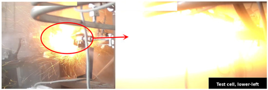
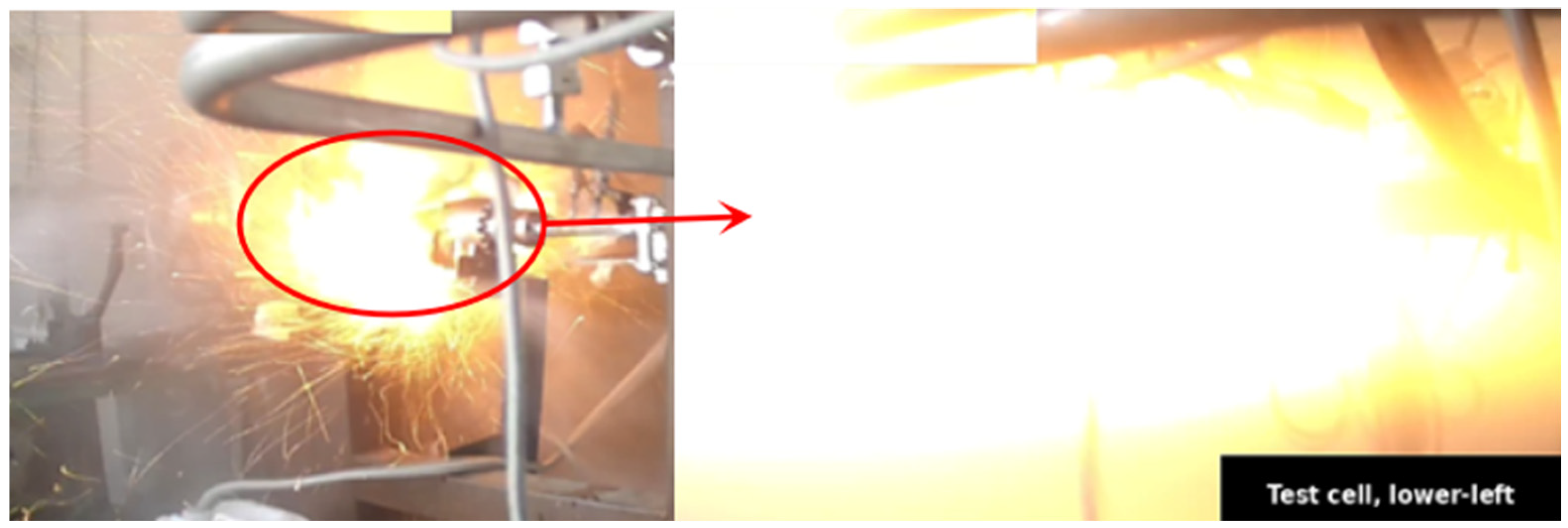
The third test utilized a different loading profile to simulate engine pulse ignition, characterized by multiple rapid load-and-unload cycles. The motor accelerated from 0 to 27,000 rpm while the main valve was actuated three times in quick succession. The valve was initially opened at 18,000 rpm for 0.1 s before closing, followed by a 0.9 s interval. It was then reopened at 23,000 rpm for another 0.1 s and subsequently closed, followed again by another 0.9 s interval. The valve opened a third time at 27,000 rpm for 0.1 s before closing once more. When the motor speed reached 32,000 rpm, a catastrophic failure of the pump occurred. The initial structural failure resulted in H2O2 leakage from the damaged pump body, which then triggered a secondary explosion at the test stand. Surveillance footage of the event is shown in Figure 1.
Figure 1.
Catastrophic failure of Pump No. 2 captured by surveillance camera.
2.2. Micro-CT Scanning Analysis
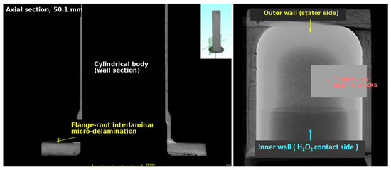
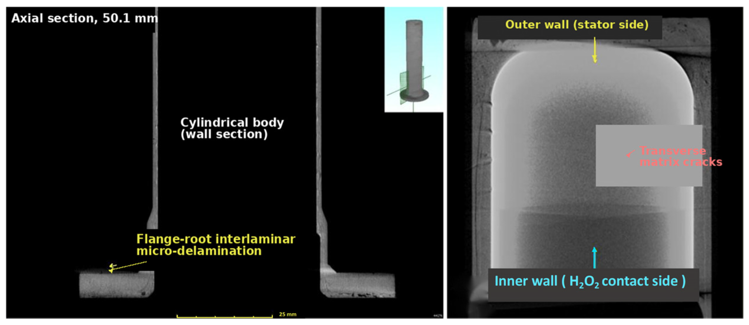
To investigate the root cause of the sleeve failure, micro-computed tomography (micro-CT) scanning was performed on the recovered CFRP sleeve fragments. Micro-CT has been widely employed for non-destructive damage characterization of CFRP composites under fatigue loading [19,20]. Simanjuntak et al. [19] demonstrated that micro-CT combined with scanning electron microscopy can effectively reveal microstructural damage evolution in various CFRP laminate configurations, including matrix cracking, fiber–matrix debonding, and delamination. Zheng et al. [20] further characterized early fatigue damage in CFRP unidirectional laminates, showing that initial defects originate in resin-enriched areas and concentrate near specimen edges. This examination identified defects of varying sizes distributed throughout the sleeve wall, with a pronounced concentration of damage on the inner surface that was in direct contact with the H2O2 medium. Representative micro-CT images are shown in Figure 2.
Figure 2.
Micro-CT images of the failed CFRP sleeve.
Two predominant damage features were identified. First, transverse cracks were observed propagating through the matrix perpendicular to the fiber direction (Figure 2). These cracks originated at the inner surface and extended into the interior of the wall, indicating that the cyclic internal pressure was the primary driving force for crack initiation. Second, micro-delamination was detected at the fiber–matrix interfaces and between adjacent plies (Figure 2). The delaminated regions were predominantly located at the tail end and flange areas, where stress concentrations are expected due to geometric discontinuities. These morphologies are consistent with the findings of Pakravan and Taheri-Behrooz [21], who showed that impact-induced delamination in carbon and epoxy laminates significantly reduces fatigue life through progressive damage accumulation.
The combination of transverse matrix cracking and interlaminar micro-delamination formed an interconnected network of defects, which created potential pathways for H2O2 penetration through the sleeve wall. Notably, the defect density was much higher near the inner surface than near the outer surface. This gradient suggests that the damage was driven predominantly by internal pressure loading and direct chemical exposure to H2O2, rather than by external mechanical loads alone.
2.3. Failure Mechanism Analysis
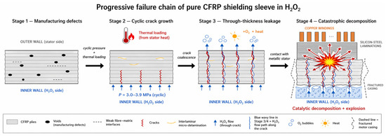
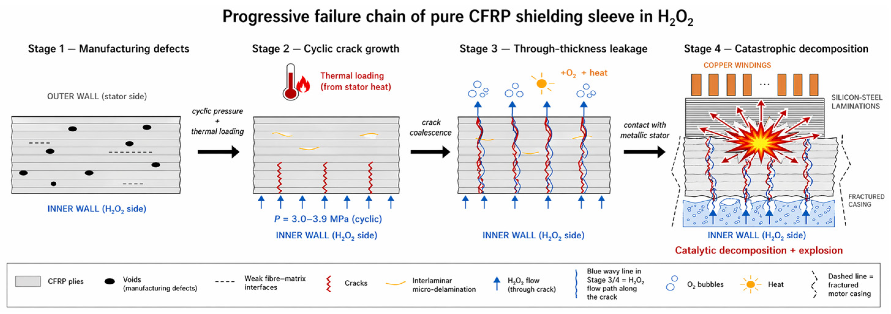
Based on the micro-CT observations and the accident reconstruction, a progressive failure mechanism was identified for the pure CFRP shielding sleeve operating in H2O2 media under cyclic pressure loading. The failure process can be divided into four stages.
In stage 1, manufacturing-induced micro-defects (voids and weak fiber–matrix interfaces) inherent to the filament winding process act as initiation sites for subsequent damage [11].
In stage 2, repeated pressure cycling combined with thermal loading and possible water-hammer impacts induces stress concentrations at the fiber–matrix interfaces. These concentrations are amplified by the modulus and CLTE mismatch between the fibers and the epoxy matrix. Interfacial debonding then initiates, and micro-cracks propagate and coalesce within the matrix, consistent with the fatigue mechanisms reported by Venkatachalam and Murthy [13]. Environmental exposure combined with fatigue further accelerates matrix degradation and interface debonding [22].
In stage 3, the interconnected crack network penetrates the full wall thickness, allowing H2O2 to seep through. H2O2 acts as a strong oxidant capable of degrading the epoxy matrix [18]. Contact with the higher-temperature stator components triggers partial thermal decomposition, whose exothermic reaction further accelerates crack growth.
In stage 4, H2O2 reaches the stator core and copper windings, where rapid catalytic decomposition produces large volumes of oxygen and heat. The resulting internal pressure and temperature rise exceed the sleeve’s structural capacity, causing a catastrophic explosion. The secondary explosion occurred as leaked H2O2 continued to decompose after the initial structural failure.
FEA of the pure CFRP sleeve confirms that fiber fracture is unlikely under the design loading [8]. The dominant failure mode is cumulative matrix damage and interfacial debonding that progressively degrades sealing integrity. Chemical and thermal exposure can reduce CFRP tensile strength by up to 35%, and the synergistic effect of environmental and mechanical loading significantly accelerates composite degradation [22].
The complete failure mechanism is summarized schematically in Figure 3.
Figure 3.
Schematic of the four-stage progressive failure mechanism of the pure CFRP sleeve in 98% H2O2 under cyclic pressure.
2.4. Implications for Sleeve Design Improvement
The failure analysis reveals that the fundamental weakness of the pure CFRP sleeve lies in its inability to maintain a hermetic seal against H2O2 after prolonged cyclic pressure loading. The epoxy matrix is inherently susceptible to micro-cracking and interfacial debonding under combined mechanical and environmental loading [12,13,22]. Once through-thickness cracks form, no barrier exists to prevent the highly reactive H2O2 from reaching the metallic stator components.
To address this deficiency, an additional sealing and barrier layer must be introduced on the inner surface of the CFRP sleeve. This layer must satisfy four concurrent requirements. First, it must provide excellent chemical resistance to concentrated H2O2 over the full service life. Second, it must remain compact and impermeable to block H2O2 penetration under cyclic pressure. Third, it must bond reliably with the outer CFRP layer while remaining electrically non-conductive, so that eddy-current losses are not reintroduced. Fourth, it must be manufacturable with sufficient dimensional precision to meet the tight tolerance of the motor air gap. These considerations motivated the PEEK–CFRP composite sleeve proposed in the present study.
3. Design of the PEEK–CFRP Composite Stator Shielding Sleeve
3.1. Limitations of the Metallic Sleeve and Motivation for a Non-Metallic Design
Prior to the composite sleeve, the electric pump employed a GH4169 (Inconel 718 equivalent) high-temperature alloy sleeve with a density of 8.24 g/cm3. According to the electromagnetic/thermal design input for the project, this metallic sleeve was assigned an eddy-current loss of approximately 5 kW at the representative 33,000 rpm operating condition. This value corresponds to about 10% of the rated 50 kW shaft power, which implies a substantial Joule-heating source in the sleeve wall. The multi-kilowatt order of magnitude is consistent with the literature on conductive sleeves in high-speed PMSMs [4,5].
The resulting temperature rise poses a direct safety hazard. The working medium, 98% H2O2, is thermally unstable and undergoes rapid exothermic decomposition once the local temperature exceeds its decomposition threshold [2,18]. The combined effect of high eddy-current loss, elevated temperature, and propellant decomposition risk renders the metallic sleeve unsuitable for long-duration or repeated operation.
Non-metallic composite sleeves made from electrically insulating materials can fundamentally eliminate eddy-current losses [5,8]. Both PEEK and carbon fiber are insulating or exhibit very low conductivity in the transverse direction, so a PEEK–CFRP composite sleeve produces negligible eddy-current losses, which reduces the thermal load on the motor and working medium and allows higher power densities. However, as shown in Section 2, a pure CFRP sleeve cannot maintain a hermetic seal against H2O2 under prolonged cyclic pressure. The improved design must therefore combine the structural advantages of CFRP with an effective sealing and chemical barrier layer.
3.2. Material Selection for the Inner Liner
When selecting liner materials, several factors must be taken into account. The metal sleeve (GH4169/Hastelloy, GaonaAeroMaterial Co., Ltd., Beijing, China.) provides excellent corrosion resistance; however, its high electrical conductivity results in approximately 5 kW of eddy-current loss at 33,000 rpm. This loss poses a significant risk of excessive thermal decomposition of the propellant, rendering it unsuitable for our needs. Additionally, the mass density of 8.24 g/cm3 is significantly higher than that of composite materials, which further disqualifies it from consideration [23]. On the other hand, pure CFRP (carbon fiber reinforced polymer) sleeves eliminate eddy-current losses. However, as discussed in Section 2, they exhibit a four-stage progressive failure mechanism that cannot guarantee long-term sealing integrity. CFRP sleeves with coatings, such as epoxy, also present issues, as they are prone to cracking under cyclic pressure and do not provide a durable sealing barrier. Therefore, they are excluded from selection as well [24]. Therefore, this section evaluates four performance indicators for four engineering thermoplastics: polytetrafluoroethylene (PTFE), polyimide (PI), and polyetheretherketone (PEEK), against the four requirements. The property comparison (Table A1) is based on manufacturer datasheets [25,26,27] and the study of Rae et al. [28] on PEEK 450G.
PTFE is known for its excellent chemical resistance; however, it is mechanically inadequate. Its tensile strength is only 22 MPa and its compressive strength 5 MPa at 1% strain [26], and its CLTE of 130 ppm/K causes a large thermal mismatch with the CFRP overwrap. PTFE also exhibits pronounced cold flow at ambient temperature.
PI (Vespel SP-1) has high strength (86.2 MPa) and low creep [25]; however, it is disqualified on three counts. Firstly, it is susceptible to hydrolytic degradation when exposed to hot aqueous environments, particularly with strong oxidizers. Secondly, its water absorption (1.0–1.3% [25]) is more than double that of PEEK (0.45% [27]). Lastly, flange fabrication from powder-based stock presents significant challenges.
PEEK is selected because its semi-crystalline aromatic backbone imparts exceptional chemical resistance, with concentrated sulfuric acid being virtually the only known aggressive solvent [14]. Its tensile yield strength (98 MPa) and modulus (4.0 GPa) [27] provide adequate toughness against crack initiation under cyclic loading. Extruded bar stock enables machining to high-dimensional precision without residual porosity [14]. Thermoplastic matrices achieve very low permeation rates with damage-free microstructure [17], a barrier capability that extends to liquid-phase H2O2. Unlike thermoset epoxies, PEEK does not suffer progressive delamination under thermal-mechanical cycling.
A key consideration is the thermal expansion mismatch between PEEK (CLTE ≈ 55 ppm/K below Tg [27]) and the filament–wound CFRP laminate (effective hoop CLTE 2–8 ppm/K). Rather than matching these coefficients, the dual-layer design exploits the mismatch. On cool-down from the winding temperature, the PEEK liner develops small compressive hoop prestress, enhancing sealing contact between the two layers. Therefore, the PEEK–CFRP double-layer structure achieves an optimal balance across multiple dimensions under current conditions, including chemical protection, structural strength, electromagnetic properties, dimensional stability, and process feasibility.
3.3. Composite Sleeve Architecture and Dimensional Design
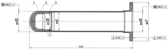
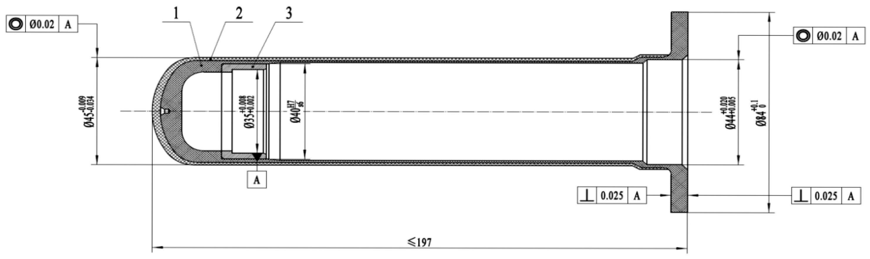
The improved composite sleeve adopts a dual-layer architecture with a PEEK inner liner and a CFRP outer reinforcement layer (Figure 4). The PEEK liner serves as the primary sealing and chemical barrier. The CFRP outer layer provides the structural strength and stiffness required to withstand the design pressure loads. The two layers exploit complementary advantages. The PEEK blocks H2O2 penetration and resists chemical degradation, while the CFRP winding provides high specific strength, high specific modulus, and near-zero eddy-current losses [8,9].
Figure 4.
Engineering drawing of the PEEK–CFRP composite stator shielding sleeve (dimensions in mm). Layers 1, 2, 3 denote the CFRP overwrap, PEEK liner, and bearing bushing, respectively.
Figure 4 identifies three concentric layers. Component 1 is the outer CFRP filament–wound overwrap, component 2 is the intermediate PEEK liner, and component 3 is the inner flow cavity. The PEEK liner is machined as an integral part with an extended radial flange at one end, providing mechanical retention against the motor housing and sealing contact with the upstream pump section. The CFRP overwrap is applied onto the cylindrical section and terminates at the flange shoulder.
The principal dimensions are summarized in Table 1. The inner bore (Ø35 mm) matches the baseline pure CFRP sleeve, so the flow cavity and stator assembly remain unchanged, ensuring direct interchangeability on existing hardware. The total wall thickness of 4.5 mm is partitioned into a 2.5 mm PEEK liner and a 2.0 mm CFRP overwrap. The baseline uses a uniform 5.0 mm CFRP wall over the same bore. The outer diameters (Ø44–45 mm) are closely matched, so the overall envelope remains compatible with the existing housing.
Table 1.
Geometric and structural parameters of the PEEK–CFRP composite sleeve.
The thickness partition follows two constraints. First, the liner must be thick enough (>1 mm) to retain sealing against machining tolerances, thermal-cycling residual strain, and in-service wear. Second, the CFRP must carry the hoop load and radially constrain the PEEK. Compared with typical Type IV composite pressure vessels, where the liner is thin (<25% of the wall) and non-structural [29,30], this design uses a proportionally thicker PEEK liner (56% of the wall), because the aggressive H2O2 medium and small Ø35 mm bore would make a thinner liner vulnerable to local damage.
The CFRP overwrap is produced by filament winding, corresponding to ≈14 plies at 0.14 mm per ply, with a hoop-dominated helical/hoop sequence. Pressure-vessel studies [29,30,31] have shown that multi-angle winding with low helical and high hoop angles outperforms single-angle designs for burst performance, supporting the hoop-dominated strategy adopted here.
The PEEK liner is machined from extruded Victrex 450G bar stock rather than injection-molded, ensuring compactness without residual porosity or weld lines. The outer surface is treated before winding to enhance adhesion with the epoxy matrix. Published studies on CF/PEEK interface quality and consolidation [9,15,16,32] support reliable bonding at the PEEK–CFRP interface. The inspection protocol (visual, ultrasonic, and micro-CT) was designed with reference to the defect categories cataloged by Fereidouni and Hoa [33]. However, due to the chemical resistance of CF/PEEK sleeves being limited by the fiber/matrix interface and the permeability of the PEEK substrate itself, it cannot provide a sealing barrier equivalent to that of pure PEEK. Its manufacturing process is complex (requiring high-temperature consolidation) and high-cost. In contrast, the PEEK–CFRP bimaterial structure uses a PEEK lining to provide chemical barrier and sealing functions, with the CFRP outer layer bearing the structural load, achieving the optimal balance between chemical resistance, structural strength, and manufacturability under current technical conditions. Therefore, this solution is a reasonable engineering choice that meets 98% H2O2 environmental requirements, cyclic pressure loads, and lightweight requirements.
3.4. Material Properties for Subsequent Stress Analysis
Material properties used in the stress analysis are summarized in Table A2 (Appendix A.2). The PEEK liner properties are obtained from the Victrex 450G datasheet [27] and Rae et al. [28]. The values for the CFRP overwrap correspond to T700-class carbon fiber with aerospace-grade epoxy at Vf = 55–60%, consistent with the measurements of Chang et al. [32] on continuous-carbon-fiber/PEEK laminates (E1 = 133.1 GPa, tensile strength 1513.8 MPa at Vf ≈ 59%). While rate-dependent and thermal effects [34,35] are acknowledged, they are not necessary for the quasi-static analysis conducted at room temperature.
The PEEK modulus (4.0 GPa) is much lower than the CFRP longitudinal modulus (135 GPa). The PEEK liner, therefore, contributes primarily to sealing and chemical resistance, while structural load bearing is dominated by the CFRP overwrap. The volume-weighted composite density is 1.42 g/cm3, representing > 80% mass reduction over GH4169 (8.24 g/cm3), with only a modest increase over the baseline pure CFRP sleeve (~1.55 g/cm3 for a 5.0 mm wall). This penalty is acceptable for the weight-critical rocket-engine application.
In summary, the PEEK–CFRP composite sleeve addresses the failure mechanism identified in Section 2 by introducing a chemically resistant, impermeable PEEK inner liner that blocks the H2O2 leakage pathway. Even if micro-cracks develop in the outer CFRP under cyclic pressure, the intact PEEK liner prevents H2O2 from reaching the metallic stator components. The dual-layer design eliminates the root cause of the catastrophic CFRP failure, while retaining the zero eddy-current loss and low density inherent to non-metallic composites.
3.5. Eddy-Current Loss Comparison and Motor Efficiency Improvement
The eddy-current loss in a thin-walled sleeve subjected to a rotating air-gap field is primarily influenced by the electrical conductivity of the sleeve material. To a lesser extent, factors such as the sleeve geometry and the spatial harmonic content of the air-gap field also play a role [4]. Four candidate sleeve materials were evaluated, namely Hastelloy C-276 and GH4169 as metallic options, together with pure CFRP and the PEEK–CFRP composite as non-metallic alternatives. Their electrical conductivities are summarized in Table A3 (Appendix A.3). The metallic sleeves (σ ≈ 7.7 × 10⁵ S/m for Hastelloy C-276 and 8.3 × 10⁵ S/m for GH4169) exhibit conductivity more than seven orders of magnitude higher than the PEEK liner (<10–16 S/m) and at least five orders higher than the through-thickness conductivity of the CFRP overwrap. In the PEEK–CFRP configuration, the continuous PEEK liner further interrupts any potential conductive path formed by occasional fiber-to-fiber contacts in the CFRP overwrap. As a result, a closed circumferential current loop cannot form within the sleeve wall.
Based on these conductivity data and the electromagnetic/thermal design input for the motor at the representative 33,000 rpm operating condition, the sleeve-induced eddy-current loss differs by several orders of magnitude among the four candidate materials. The GH4169 metallic sleeve dissipates approximately 5.0 kW of eddy-current loss at the design operating point, corresponding to about 10% of the rated 50 kW shaft power. This value is consistent with published analytical and numerical studies of eddy-current losses in conductive retaining sleeves and shielding cylinders of high-speed PMSMs [4,5]. Hastelloy C-276 shares the same conductive-metal class and is therefore expected to remain in the same order of magnitude. In contrast, the pure CFRP and PEEK–CFRP composite sleeves are treated as effectively zero-loss configurations at the sleeve level, because the in-plane conductivity of the CFRP overwrap (transverse to the fiber direction) and that of the PEEK liner are both several orders of magnitude lower than those of the metallic alternatives. As a result, the induced eddy-current density and the associated Joule dissipation are negligible compared with the GH4169 baseline.
Replacing the GH4169 sleeve with the PEEK–CFRP composite therefore removes the dominant sleeve-loss channel without any change to the stator winding, rotor magnets, or control strategy, and translates directly into improved motor efficiency at the rated operating point. A second-order benefit is the reduced thermal load on the motor. The 5 kW of eddy-current heating previously dissipated into the H2O2 working fluid and the stator core would have increased the risk of thermally driven propellant decomposition. Removing this heat source eliminates a multi-kilowatt parasitic source from the motor.
In summary, the PEEK–CFRP composite sleeve removes the multi-kilowatt sleeve-loss channel associated with the GH4169 baseline and eliminates a major parasitic heat source from the motor. Together with the chemical barrier function established in Section 3.2 and the structural safety margins in Section 4, this electromagnetic benefit completes the engineering case for the PEEK–CFRP composite sleeve as the preferred solution for the electric-pump application.
4. Finite Element Stress Analysis
4.1. Finite Element Model and Analysis Setup
The finite element analysis was performed The composite sleeve was modeled as a three-dimensional shell, with the two material layers defined through the ACP composite module. Shell elements with full through-thickness integration were utilized. Given that the sleeve has a thickness of 4.5 mm, which is small compared to its diameter of 44 mm and length of 197 mm, a shell formulation effectively captures the membrane-dominated behavior of the cylindrical structure. The PEEK inner liner was represented as a single isotropic sub-laminate with a thickness of 2.5 mm. The CFRP overwrap was modeled as a 2.0 mm, hoop-dominated orthotropic laminate, using the effective elastic constants provided in Table A2.
The boundary conditions and loading arrangement are depicted in Figure A1 (Appendix B). The outboard face of the integrated PEEK flange is fixed in all six degrees of freedom, while all other surfaces remain free. Internal pressure is applied uniformly to the inner surface of the PEEK liner. The structural load magnitudes were drawn from a preliminary CFD analysis of the H2O2 flow through the rotor-sleeve annular gap at 32,000 rpm. The CFD result is shown in Figure A2 (Appendix B). The maximum static pressure reaches 2.79 MPa near the upstream end. The minimum falls to 1.08 MPa downstream. A uniform 3 MPa steady pressure was then adopted in the structural model to envelope the CFD maximum. The 3.9 MPa pulse pressure, 1.3 times the steady value, represents the transient over-pressure recorded during rotor-speed ramping from 18,000 to 32,000 rpm on the pump.
A steady load of 3 MPa is applied in a single static step. Additionally, a pulse load of 3.9 MPa is applied as a triangular time history, reaching its peak at t = 0.1 s. Inertia is included in the transient analysis. The pulse stress scales linearly with a pressure ratio of 1.30, confirming that the response is essentially quasi-static.
A three-level mesh-independence study showed that the peak von-Mises stress converges to within 0.6% for a mesh size of 1.5 mm (see Table A4, Appendix A.4). The 1.0 mm fine mesh of about 82,300 elements was therefore adopted. Local refinement down to 0.5 mm was applied at the flange root fillet to resolve the stress concentration.
4.2. Steady-State Stress Analysis (3 MPa)
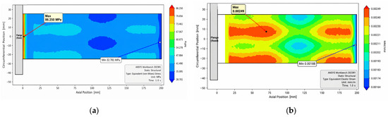
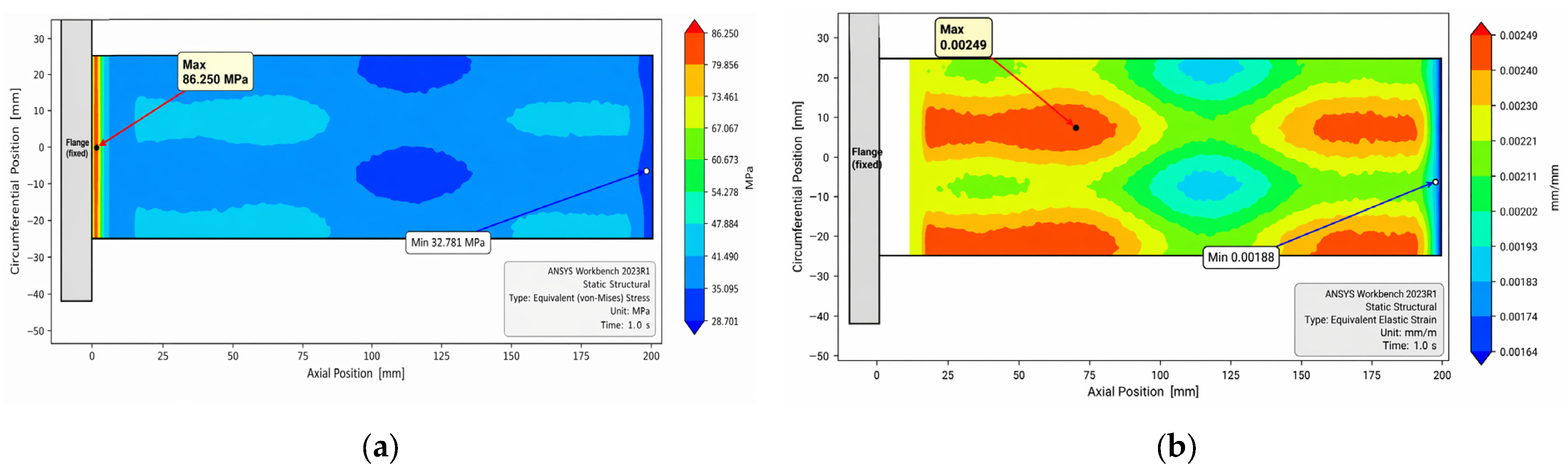
Figure 5 shows the equivalent von-Mises stress and equivalent elastic strain distributions under a steady internal pressure of 3 MPa. The peak stress concentrates in a narrow band at the root of the integrated PEEK flange, where the cylindrical body transitions into the radial flange. Its severity is set by the internal fillet radius of 3 mm. The high-stress band extends axially over 2 to 3 mm and remains confined to the inner PEEK liner on the pressure side. Away from this region, the cylindrical body shows a nearly uniform membrane stress of 38 to 48 MPa along its full length. This value is consistent with the analytical thin-wall solution for a closed-ended composite cylinder at 3 MPa.
Figure 5.
Steady-state FEA results at 3 MPa. (a) Equivalent (von-Mises) stress distribution-steady state P = 3 MPa; (b) Equivalent elastic strain distribution-steady state P = 3 MPa.
The strain field reaches its maximum in the cylindrical body rather than at the stress-concentration location. This inversion between stress and strain maxima reflects the different roles of the two layers. The peak stress is driven by geometric concentration at the flange root in the compliant PEEK liner. The peak strain is governed by the circumferential membrane deformation of the full composite wall over the long cylindrical span. The radial displacement at mid-length is about 0.08 mm, comfortably within the radial clearance of the stator assembly.
A layer-by-layer decomposition of the through-thickness reveals a clear partitioning of the load. In the cylindrical body, the CFRP hoop stress averaged through the overwrap thickness is about 95 MPa. The PEEK hoop stress in the same region is only about 15 MPa. The ratio follows directly from the in-plane stiffness contrast, with an effective CFRP hoop modulus of approximately 100 GPa against 4.0 GPa for PEEK. The CFRP overwrap, therefore, carries the structural load while the PEEK liner performs the sealing function, exactly as intended. The peak stress at the flange root lies in the PEEK because the CFRP overwrap terminates at the flange shoulder and does not extend into the flange.
4.3. Pulse Stress Analysis (3.9 MPa)
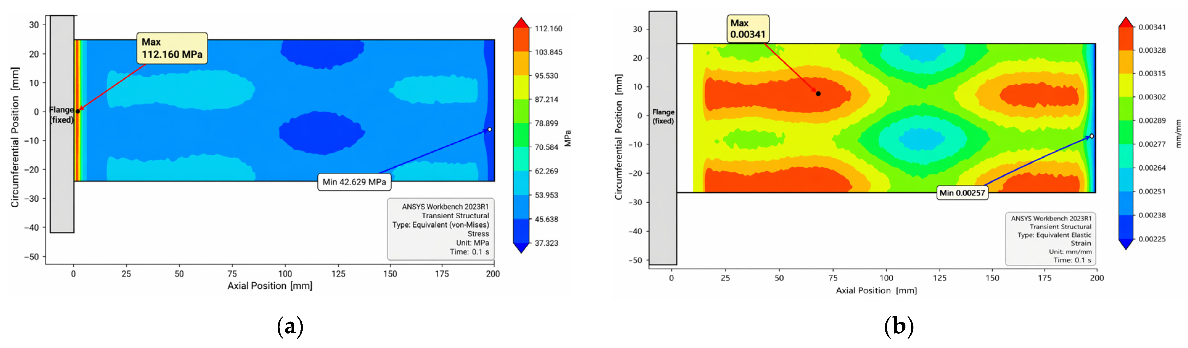
Figure 6 shows the corresponding results for the pulse load case at the peak-pressure time t = 0.1 s. The peak von-Mises stress and peak strain occur at the same locations as in the steady case. Both values scale approximately linearly with the pressure ratio of 1.30, within a 5% numerical tolerance. This linear scaling indicates that the sleeve responds quasi-statically under the imposed pulse duration. Inertial and wave-propagation effects remain negligible at these loading rates. The cylindrical-body membrane stress rises to 49 to 62 MPa. The CFRP hoop stress in the cylindrical body rises to about 125 MPa.
Figure 6.
Pulse FEA results at 3.9 MPa, t = 0.1 s. (a) Equivalent (von-Mises) stress distribution-Steady state P = 3.9 MPa (t = 0.1 s); (b) Equivalent elastic strain distribution-Steady state P = 3.9 MPa (t = 0.1 s).
Peak stress and strain values for both load cases are summarized in Table 2.
Table 2.
Peak stress and strain in the PEEK–CFRP sleeve under the two FEA load cases.
4.4. Safety Margin Evaluation
The safety margin of the composite sleeve was evaluated using the von-Mises yield criterion for the PEEK liner and the maximum-stress plus Tsai–Wu criteria for the CFRP overwrap. The Tsai–Wu failure index was computed at each integration point of every ply, and the maximum across all plies is reported in Table 3.
Table 3.
Material-level safety factor evaluation of the PEEK–CFRP sleeve.
Safety factors in the cylindrical body remain uniformly high. The CFRP fiber-direction stress ratio exceeds 17 in both load cases, so fiber tensile failure is ruled out. The transverse tension ratio is 1.8 under the steady load and 1.3 under the pulse load. The narrower transverse margin is typical of filament–wound composites with hoop-dominated layups, and motivates the use of the Tsai–Wu quadratic interaction criterion. The Tsai–Wu failure index remains well below the failure threshold of 1.0 in both load cases.
The pulse peak of 112.16 MPa at the flange fillet slightly exceeds the quasi-static yield of PEEK 450G. Three factors mitigate this local exceedance. First, the strain-rate dependence of PEEK 450G raises the effective yield by roughly 15 to 20% at the pulse strain rate near 10−2 s−1 [28]. Second, the surrounding CFRP overwrap stays fully elastic at a Tsai–Wu index of 0.58, so localized PEEK plasticity acts as an energy-absorbing mechanism and blunts the stress concentration. Third, the behavior is consistent with the intended hierarchical failure design, in which the PEEK liner acts as a sacrificial barrier while the CFRP overwrap provides the ultimate strength reserve.
The analysis establishes that the PEEK–CFRP sleeve sustains both the steady 3 MPa and the pulse 3.9 MPa pressures with adequate structural margin. The localized PEEK over-yield at the flange fillet is physically consistent with the dual-layer load-sharing concept and does not compromise overall integrity. The redesigned composite sleeve, therefore, satisfies the structural requirements of the electric-pump application.
4.5. Dynamic Structural Stability Assessment
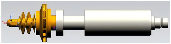
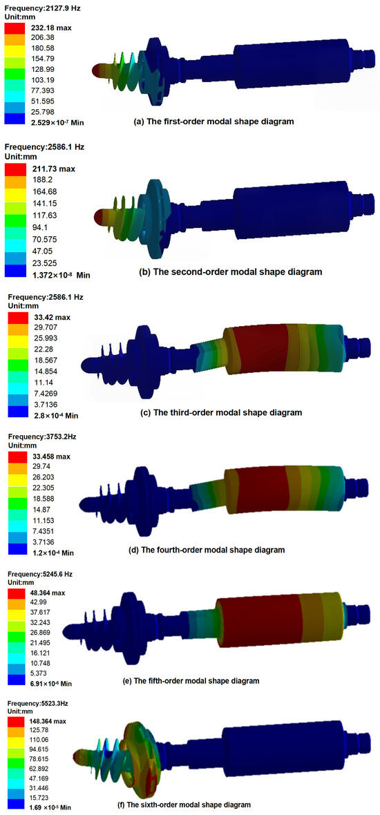
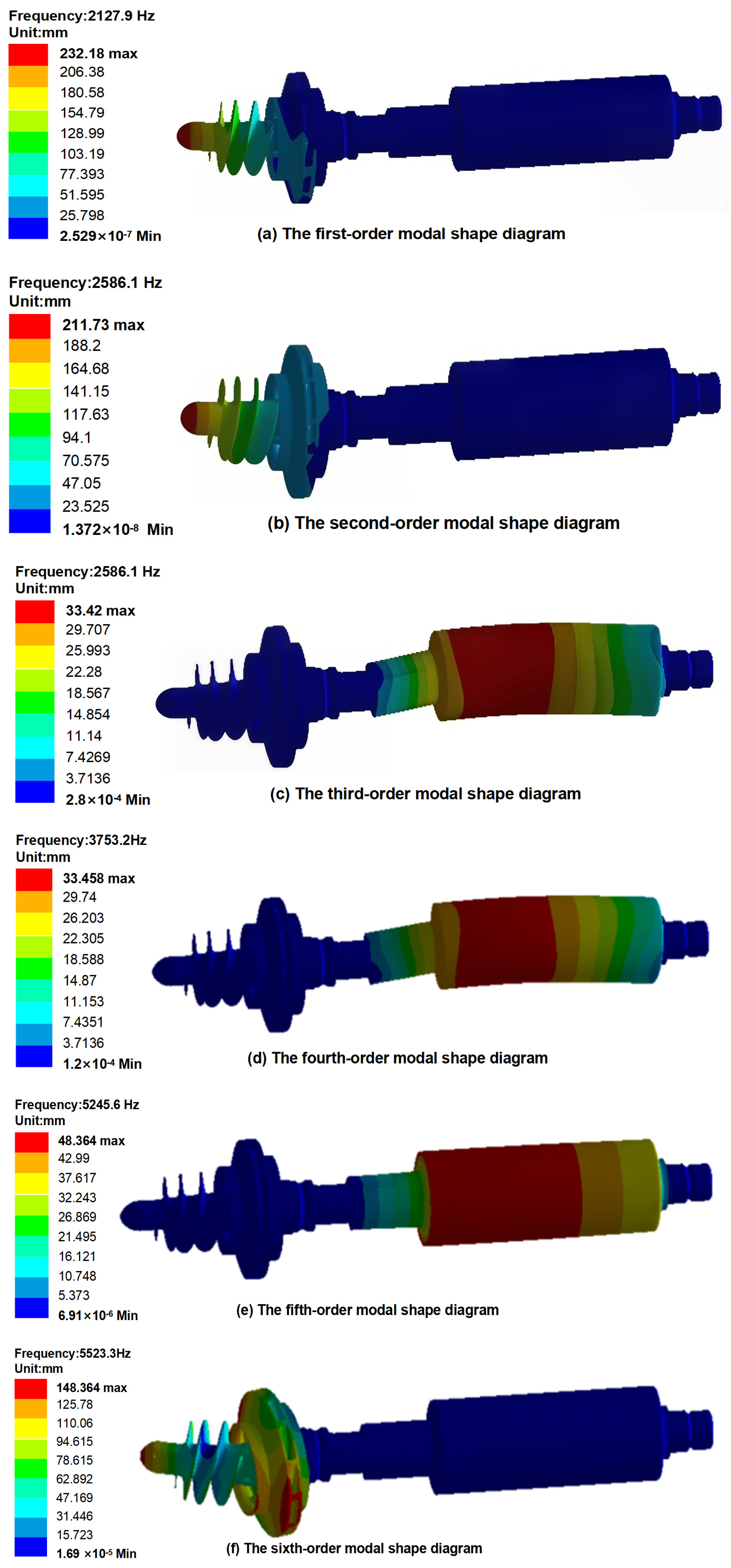
This section presents a three-dimensional finite element modal analysis of the motor rotor system. Figure 7 displays the 3D model of the motor rotor. We will analyze the modes of the rotor system, and the first six mode shapes are illustrated in Figure 8.
Figure 7.
3D model of the motor rotor.
Figure 8.
Rotor modal shape diagram.
From Figure 8, it can be seen that the first-order intrinsic frequency of the rotor is 2127.9 Hz, which is the shaft extension end bending vibration. According to the intrinsic frequency calculation, the actual first-order critical speed of the HSPMM is 127,674 rpm, the motor working point avoids the critical speed point, and there is no resonance point of the rotor within 40,000 rpm from the simulation data. The first- and second-order vibration patterns are similar, but the two impeller vibration patterns are slightly different, with the second-order vibration deformation being larger. The third, fourth, and fifth-order rotor vibration patterns are characterized by overall rotational vibration of the rotor. The third- and fourth-order vibration patterns are closer, whereas the fifth-order deformation is more serious than the first two. The sixth-order rotor vibration mode is also characterized by bending vibration of the shaft extension end, and the impeller deformation is more serious than of the second-order mode.
5. Experimental Validation
5.1. Test Medium Selection
All structural experiments reported in this section were conducted using deionized water as the test medium instead of 98% hydrogen peroxide (H2O2). This decision is based on three key considerations. The failure modes under investigation include sealing integrity, pressure fatigue, hydrostatic burst, hydraulic performance, and long-duration thermal response. These aspects are primarily governed by the mechanical properties of the sleeve and the density and viscosity of the working fluid, making them fluid mechanics issues rather than chemistry problems. Deionized water has a density and viscosity that are within 5% and 15%, respectively, of those of 98% hydrogen peroxide at the test temperatures, making it a mechanically suitable surrogate for pressure, flow, and burst testing.
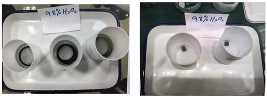
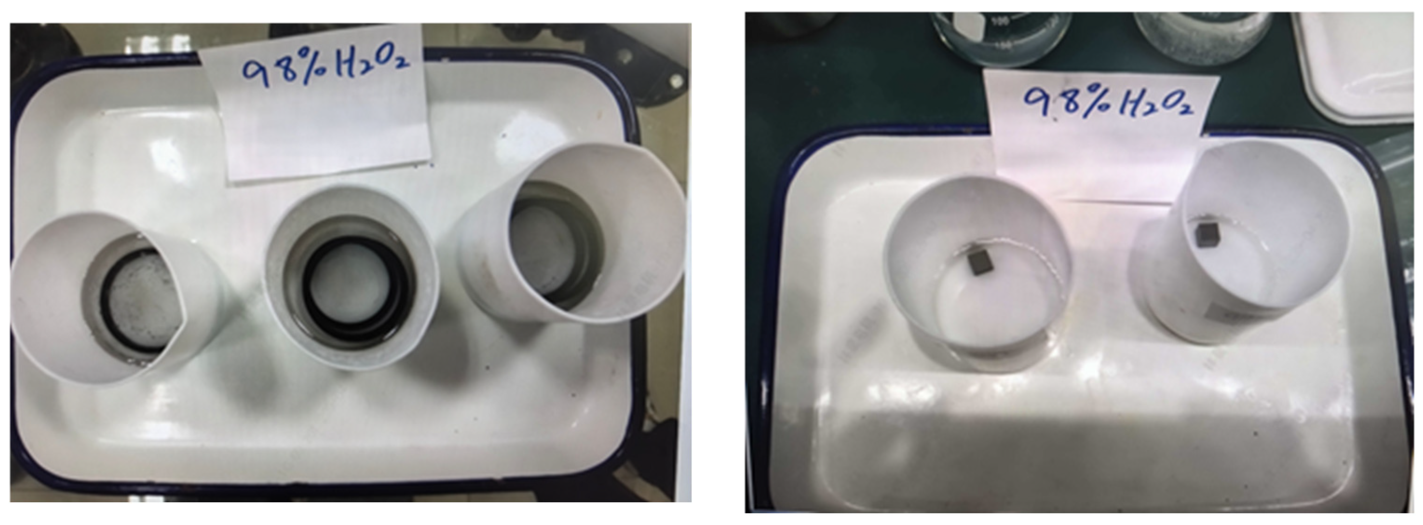
In this study, part immersion tests were conducted. The specific process involves directly soaking motor-related parts in 98% H2O2 concentration for 24 h at room temperature (25 °C). After 24 h, the surface was checked for bubbles and corrosion marks. As shown in Figure 9, the results show that the surface of the PEEK material has no air bubbles or corrosion marks, ensuring material compatibility.
Figure 9.
Soaking test.
The chemical compatibility of the load-path material has been independently verified at the material level. The ASTM D543 immersion test conducted on the PEEK 450G inner liner demonstrated a mass uptake of less than 0.2% and a tensile strength retention of over 98% after 30 days in 98% hydrogen peroxide (H2O2). The CFRP overwrap is protected by the PEEK liner and does not come into direct contact with the fluid. Conducting hundreds of pressure cycles and hydrostatic burst tests in 98% H2O2 poses significant hazards, including catalytic decomposition, spontaneous combustion of contaminants, and explosion risks in a pressure vessel. These hazards outweigh the additional information that could be gained at this stage of development.
This two-level verification strategy combines material-level chemical compatibility with sleeve-level structural testing in water. It provides defence-in-depth against both the chemical and the mechanical failure modes of the sleeve. Water-based structural testing is also the industry-standard practice for validating composite pressure vessels intended for oxidizer service, including liquid-oxygen and high-concentration H2O2 applications.
The test rig used for the pressure-related experiments (Section 5.2, Section 5.3 and Section 5.4) is described here. The specimen is placed inside an explosion-proof tank, which features independent systems for pressurization, temperature control, and data acquisition. A K-type thermocouple is attached to the outer wall of the sleeve to monitor the surface temperature. Additionally, a pressure transducer on the inlet line records the applied hydraulic pressure.
5.2. Pressure-Retention (Proof) Test
The pressure-retention test verifies sealing against the nominal operating pressure. The sleeve cavity was filled with deionized water, pressurized to 3.00 MPa, held for 5 min, and then de-pressurized. This sequence was repeated for five independent cycles. Between cycles, the specimen was disassembled and inspected visually, and the inner-bore diameter was measured with a plug gauge at three axial positions.
The pressure drop during each 5-min hold remained below 0.5% of the applied pressure in all five cycles. No visible leakage, no flange or cylindrical-body deformation, and no out-of-tolerance bore dimensions were observed. All bore measurements stayed within the machining tolerance of Ø35 + 0.008/+0.002 mm. The full cycle-by-cycle results are provided in Table A5 (Appendix A.5).
5.3. Pressure-Fatigue Test
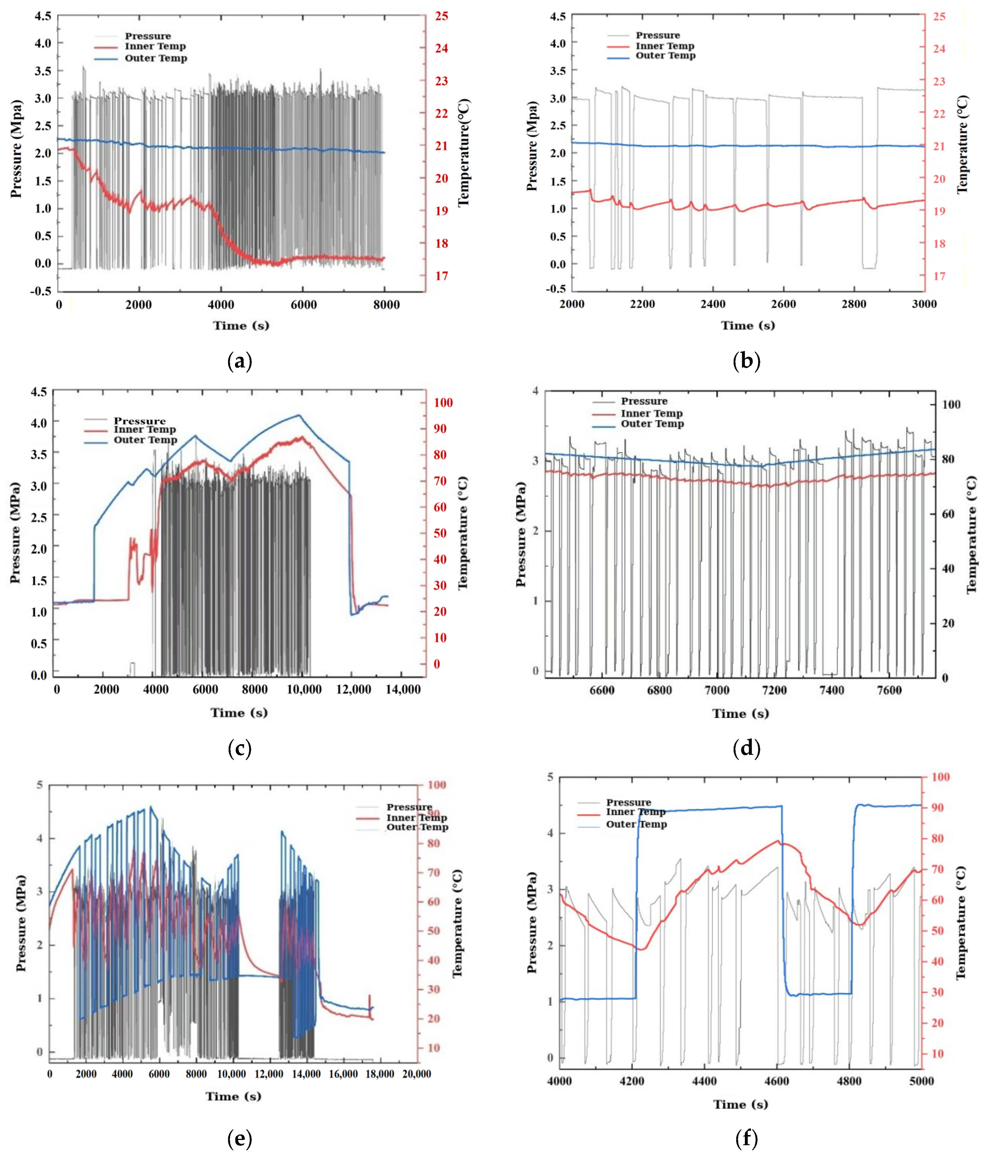
The pressure-fatigue test evaluates the sleeve’s resistance to cyclic pressure loading in three environmental conditions representative of the actual service envelope of the electric pump. These are ambient-temperature cycling, elevated-temperature cycling at the sustained-operation temperature, and thermal-cycling between the idle and operating temperatures. Since this motor is an engineering prototype, in actual operation, a single task requires fewer than 50 pressure cycles. To verify the improved product’s performance and prevent catastrophic failures again, a fourfold margin is used, with 200 cycles per working condition. That is, each stage applied 200 pressure cycles of 0 ↔ 3 MPa, giving a cumulative total of 600 cycles. The sequence was designed so that each successive stage applies a more demanding combined mechanical-thermal loading. Failure at any stage would therefore be attributable to the combined effect of cyclic pressure and environmental temperature.
Each stage involved rapid pressurization to 3 MPa, followed by an immediate release. Stage 1 was conducted at an ambient temperature of 25 °C, with the outer wall maintaining a stability of ±0.5 °C, while the inner cavity’s temperature ranged between 17 °C and 21 °C. In Stage 2, fluid was preheated to 90 °C; during this stage, the outer wall remained steady at a temperature of 90 °C to 95 °C, and the inner cavity’s temperature was between 75 °C and 85 °C. Stage 3 involved cycling the fluid between 25 °C and 90 °C in 20 groups of 10 cycles each. The recorded histories of pressure and temperature for all three stages are illustrated in Figure A3 (Appendix B).
After each stage of testing, the specimen underwent three inspections. The first was a visual inspection of both the CFRP outer surface and the PEEK bore. The second involved a repeated proof test similar to the pressure-retention test. Finally, sampling CT scans was performed at both the upstream and mid-length regions of the specimen.
After completing the three testing stages, each specimen was examined using a miniature CT scan (Nikon XT H 225 ST, Nikon Corporation, Tokyo, Japan) with a voxel resolution of 15 μm. This scan was capable of detecting cracks as small as 30 μm and pores with a minimum diameter of 50 μm. Under these testing conditions, no visible cracks, interlaminar delamination, leakage, or pore defects exceeding the detection thresholds were observed in the specimens at any of the three stages. Throughout each repeated withstand pressure test, the pressure drop remained below 0.5% within the first five minutes. The cumulative results after all 600 cycles are summarized in Table 4.
Table 4.
Summary of the 600-cycle pressure-fatigue test campaign.
5.4. Hydrostatic Burst Test
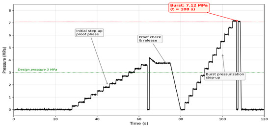
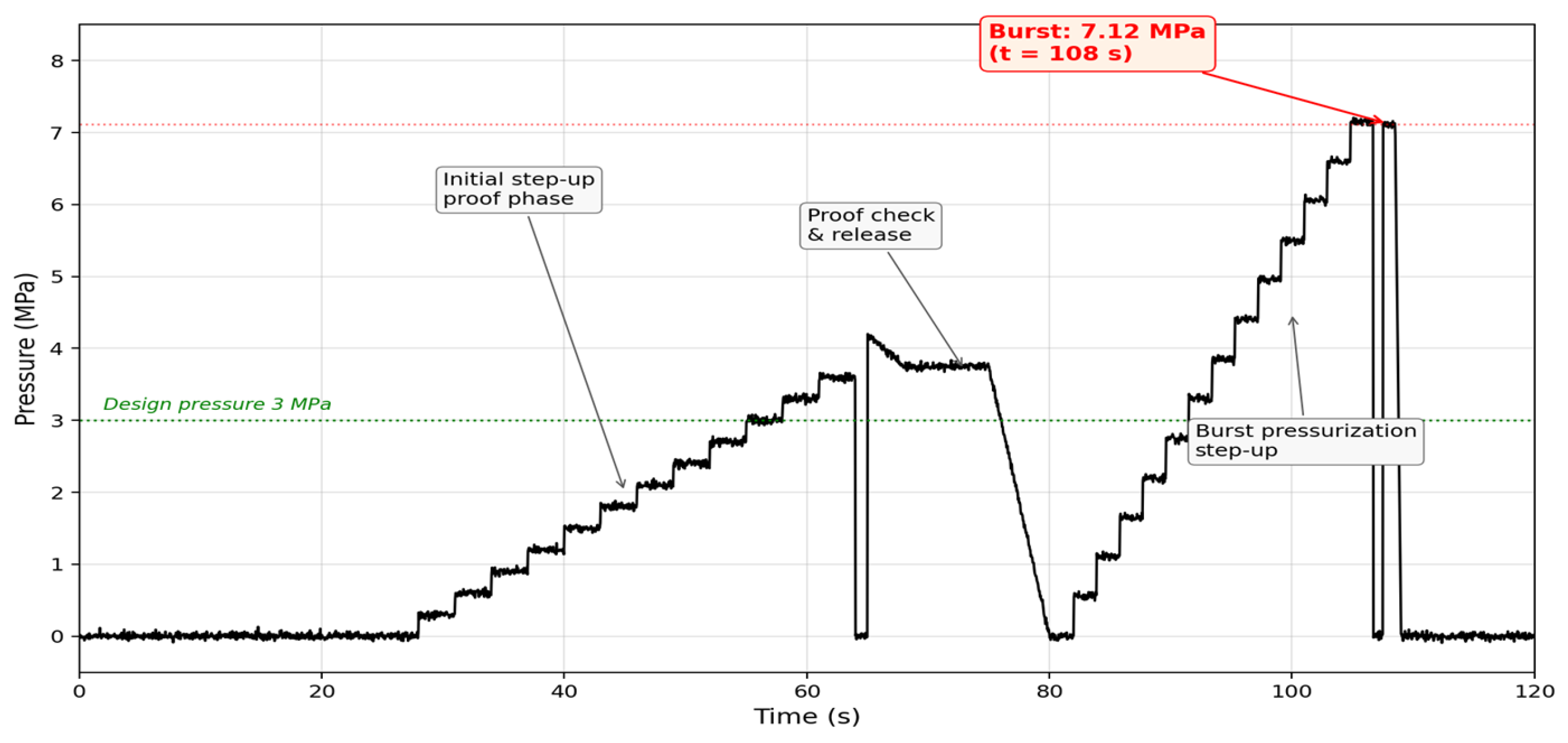
The hydrostatic burst test evaluates the ultimate strength of the composite sleeve and determines its mode of physical failure. A new, unused sleeve specimen, representative of the production configuration, was placed inside an explosion-proof tank previously utilized for fatigue testing. To enhance safety in the event of a rupture, additional reinforced containment was added around the specimen to capture any fragments. The internal cavity of the sleeve was filled with deionized water, and the pressure was gradually increased using a hydraulic intensifier. The pressure history applied during the test is shown in Figure 10.
Figure 10.
Hydrostatic burst test pressure history of the PEEK–CFRP sleeve, with failure at 7.12 MPa (2.37 × design pressure).
The initial step-up phase raised the pressure to approximately 4.0 MPa in successive 0.3 MPa increments over 40 s, with each step briefly held to verify sealing. At approximately 4 MPa (t ≈ 65 s), the system was deliberately depressurized for a visual inspection of the specimen and instrumentation, visible as the dip to zero in Figure 10 between t ≈ 75 s and t ≈ 80 s. Pressurization was then resumed in larger 0.55 MPa increments until the burst point was reached at 7.12 MPa.
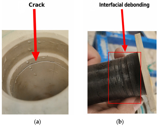
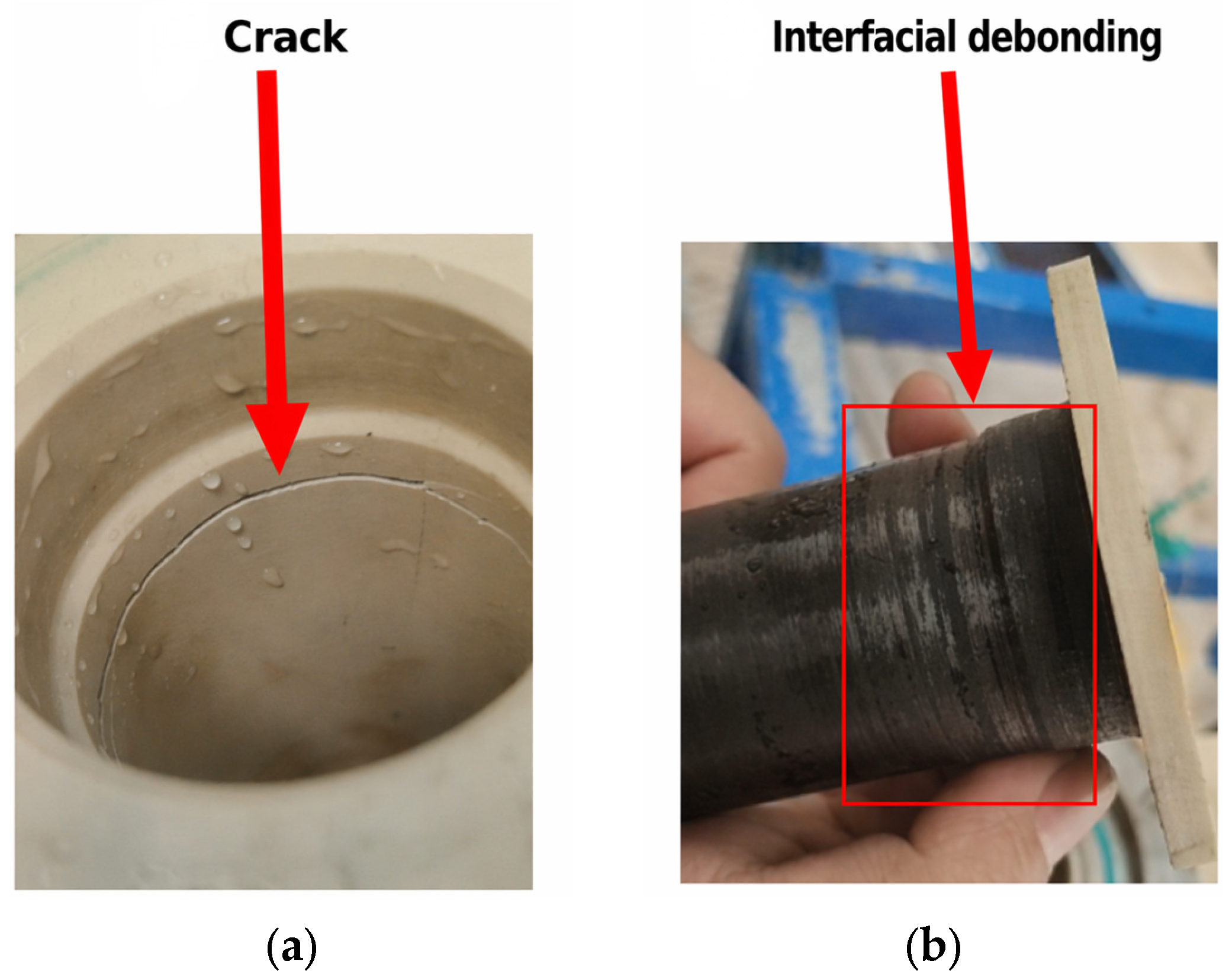
The measured burst pressure corresponds to a safety margin of 2.37 over the 3 MPa design pressure, which comfortably exceeds the engineering specification margin of 2.0 for the electric pump. Post-test examination of the specimen is shown in Figure 11. The PEEK inner liner exhibits a clear axial tensile crack extending from the flange end of the bore into the cylindrical section of the liner (Figure 11a). This is consistent with the liner being the first layer to reach its tensile strength limit under the growing internal pressure. The outer CFRP overwrap shows no through-thickness rupture and no visible fiber breakage anywhere along its length (Figure 11b).
Figure 11.
Post-burst examination. (a) Crack; (b) Interfacial debonding.
A localized zone of interfacial debonding between the CFRP overwrap and the underlying PEEK liner is visible on the outer surface in the region immediately adjacent to the PEEK crack. The debonded band is narrow axially and does not propagate circumferentially around the sleeve. The CFRP overwrap, therefore, continued to provide structural containment of the pressurized fluid up to and beyond the point at which the PEEK liner ruptured, which is the intended design behavior of the dual-layer composite. Because the test was conducted in water, the measured burst pressure represents the structural burst capacity under a chemically inert, non-impact-sensitive fluid. It is considered a conservative lower bound for the sleeve’s mechanical strength reserve in service.
This failure sequence is the hierarchy that the dual-layer design is intended to produce. The PEEK liner fails first and relieves pressure through a controlled crack, while the CFRP overwrap sustains localized interfacial debonding but no catastrophic rupture. The observed burst mode is consistent with the FEA prediction in Section 4.4, where the pulse-case stress concentration at the PEEK flange root fillet was shown to exceed the quasi-static yield of Victrex 450G. The survival of the CFRP overwrap at the burst pressure confirms the structural reserve predicted by the Tsai–Wu analysis in Table 3. The composite sleeve, therefore, exhibits a graceful-failure characteristic that safeguards the surrounding motor components. This behavior is substantially safer than the pure CFRP baseline, which failed by progressive delamination and H2O2 leakage leading to catalytic decomposition and explosion.
5.5. Hydraulic Performance Test
The hydraulic performance test verifies that the 2.5 mm PEEK inner liner, which slightly reduces the effective annular gap between the rotor and the stator shielding sleeve, does not compromise the hydraulic characteristics of the electric pump. The test was conducted on the complete pump assembly using water as the working fluid. Two configurations were tested back-to-back on the same pump. Configuration A used the baseline pure CFRP sleeve with a 5.0 mm wall and Ø35 mm bore. Configuration B used the improved PEEK–CFRP composite sleeve with 2.5 mm PEEK and 2.0 mm CFRP on the same Ø35 mm bore. Since both sleeves share the same inner-bore diameter, the flow-cavity geometry seen by the working fluid is identical, and any performance difference can only be attributed to secondary effects such as surface roughness or elastic deformation of the liner.
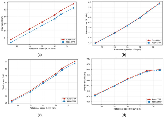
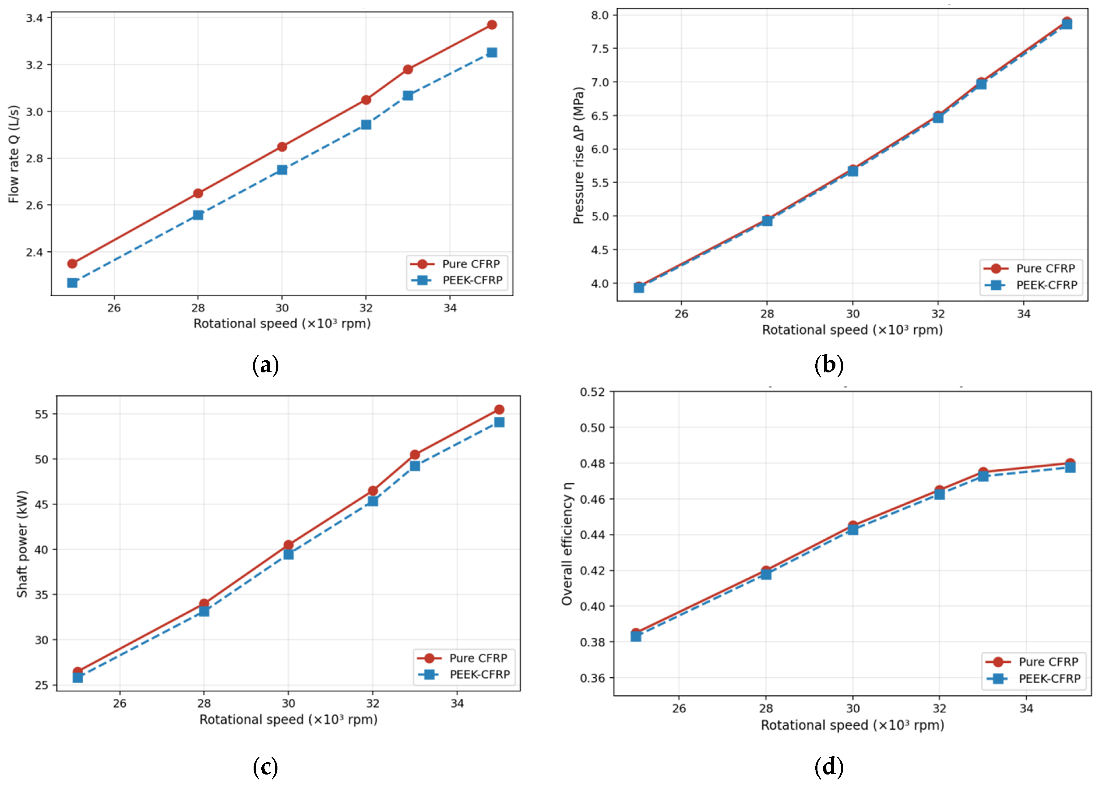
For each configuration, the pump was operated at six different rotational speeds, ranging from 25,000 to 35,000 rpm. At each speed, we measured the volumetric flow rate (Q), inlet pressure (Pin), outlet pressure (Pout), and shaft mechanical power (Pshaft) in a steady state. The overall pump efficiency (η) was calculated using the formula η = Q × (Pout – Pin)/Pshaft. The resulting hydraulic characteristics of the two configurations are compared in Figure 12 and summarized in Table 5.
Figure 12.
Hydraulic performance comparison of the pure CFRP sleeve (red) and the PEEK–CFRP sleeve (blue). (a) Flow rate vs. rotational speed; (b) Pressure rise vs. rotational speed; (c) Shaft power vs. rotational speed; (d) Pump efficiency rotational speed.
Table 5.
Hydraulic performance test results for the pure CFRP and PEEK–CFRP sleeves.
The two configurations exhibit essentially similar hydraulic characteristics across the full speed range, with closely overlapping trends in Figure 12 and matching values in Table 5. At the rated operating condition of 35,000 rpm, the PEEK–CFRP sleeve delivers a marginally lower flow rate and shaft power than the pure CFRP baseline. Pressure rise and overall efficiency remain comparable. The inner PEEK liner therefore does not materially degrade pump hydraulic performance.
5.6. Long-Duration Temperature-Rise Test
The long-duration temperature-rise test evaluates the thermal compatibility of the PEEK–CFRP sleeve with the motor operating envelope. The non-metallic composite sleeve eliminates the eddy-current losses that dominated the thermal state of the original GH4169 metallic sleeve (approximately 5 kW at 33,000 rpm). The thermal response of the present sleeve is therefore governed only by viscous dissipation in the annular fluid gap and by bearing heat conducted into the sleeve wall.
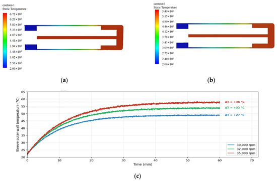
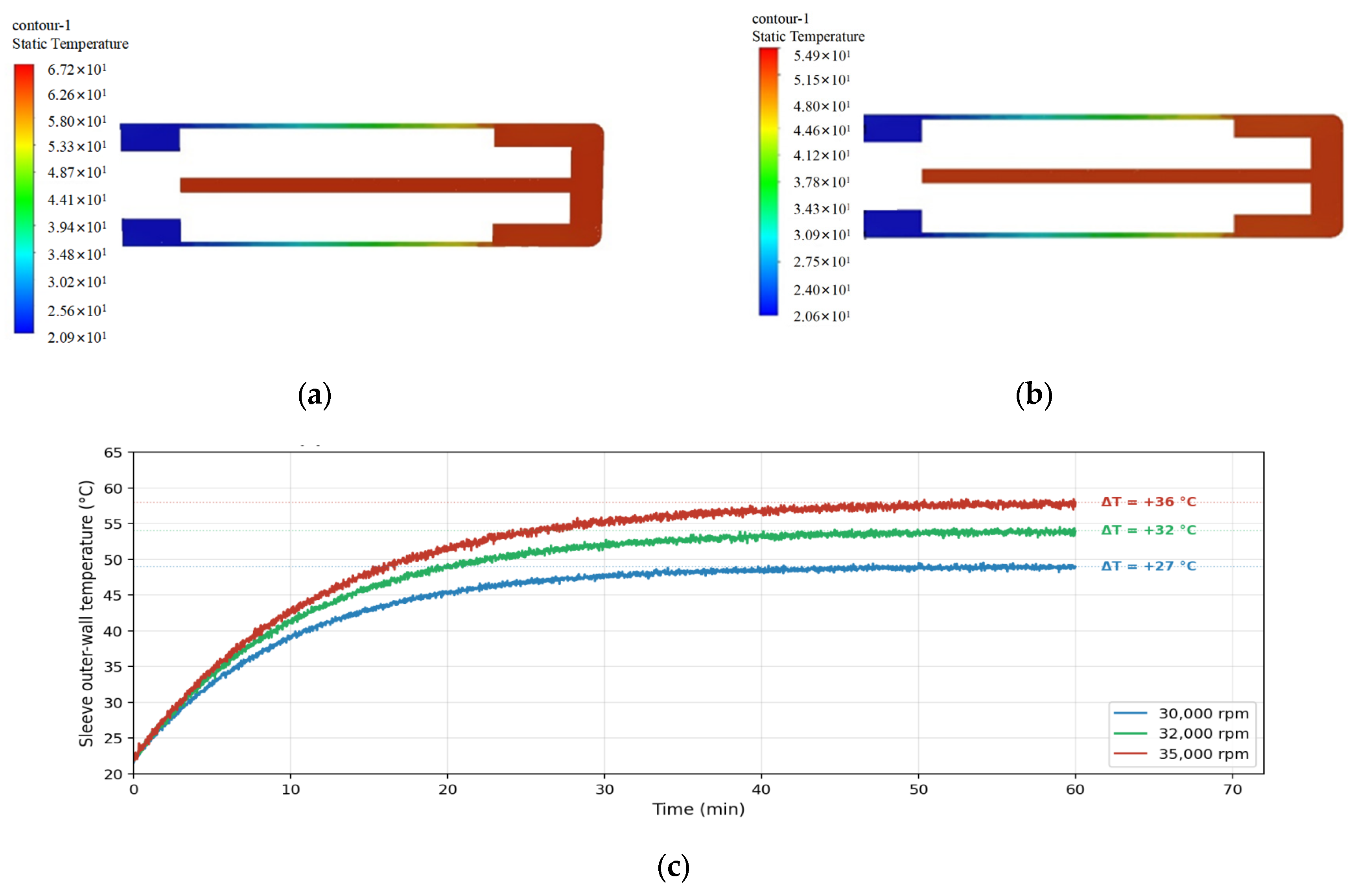
A preliminary thermal analysis was performed with both water and 98% H2O2 as coolants. The simulated steady-state wall-temperature fields for the two coolants are compared in Figure 13a,b. The H2O2 case shows a lower peak wall temperature than the water case, because H2O2 has a larger specific heat per unit volume and a larger thermal conductivity that together enhance convective heat removal from the sleeve wall. At the representative operating point of 33,000 rpm, 2.39 L/s volumetric flow, 39.2 kW motor input power, and 19 °C initial water temperature, the measured water-side temperature rise of the cooling channel stayed within 37 °C. Using a CFD-calibrated coolant flow rate of 70 g/s (water) at the measured 34 °C wall-side rise, the equivalent H2O2 mass flow rate is 100 g/s, which gives an estimated H2O2 cooling-channel temperature rise of about 45 °C.
Figure 13.
Temperature-rise evaluation of the PEEK–CFRP sleeve. (a) Water coolant: simulated T field, max 67.2 °C; (b) H2O2 coolant: simulated T field, max 54.9 °C; (c) Measured sleeve outer-wall temperature rise vs. time at three rotational speeds.
The measured temperature-rise curves for the PEEK–CFRP sleeve under continuous rotation in water at 30,000, 32,000, and 35,000 rpm are shown in Figure 13c. The sleeve outer-wall temperature rose exponentially from the 22 °C ambient and reached a steady-state value within 30 to 40 min at all three speeds. This corresponds to a first-order thermal time constant of about 10 to 12 min. The steady-state temperature rise above ambient increased monotonically with rotational speed. The maximum wall temperature recorded at 35,000 rpm is consistent with the thermal-analysis prediction and compatible with the engineering water-side record.
The temperature-rise measurement supports three conclusions. The maximum sleeve-wall temperature under the most demanding operating condition considered here, at 35,000 rpm with water coolant, is 58 °C. This value sits well below the glass transition temperature of PEEK 450G of 143 °C, so the PEEK liner remains in its full-strength, semi-crystalline state throughout the operating envelope. The water-side temperature rise remained within 37 °C, and the corrected H2O2 cooling-channel rise is about 45 °C, both within the acceptable thermal margin of the electric-pump application. These results are consistent with the design objective of the PEEK–CFRP sleeve, in that the elimination of sleeve eddy-current heating prevents the sleeve from becoming a dominant thermal source in the motor.
6. Conclusions
This study identified the failure mechanism of pure CFRP stator shielding sleeves operating in 98% H2O2 under cyclic pressure and validated a PEEK–CFRP composite sleeve as the engineering solution for the electric pump. Micro-CT evidence from the recovered sleeve fragments revealed a four-stage failure mechanism, in which manufacturing micro-defects evolve through matrix cracking under cyclic pressure and thermal loading, and then progress to through-thickness leakage and ultimately to catalytic decomposition and explosion. It should be noted that this mechanism is the most common pathway observed based on evidence gathered under the current experimental conditions (98% H2O2 and cyclic pressure of 3.9 MPa or less).
The improved dual-layer sleeve breaks this mechanism. A chemically resistant PEEK inner liner blocks the leakage pathway, while a hoop-dominated CFRP overwrap carries the structural load. Finite element analysis gave peak von-Mises stresses of 86.25 MPa under the 3 MPa steady load and 112.16 MPa under the 3.9 MPa pulse load at the PEEK flange root fillet, with Tsai–Wu safety factors of 2.9 and 1.7 for the CFRP overwrap.
The five-cycle proof test, the 600-cycle fatigue test across three thermal environments, and the hydrostatic burst test at 7.12 MPa (2.37× the design pressure) all confirmed the intended hierarchical behavior, with burst failure confined to an axial crack in the PEEK liner while the CFRP overwrap stayed intact.
In summary, under the current engineering validation conditions (600 pressure cycles, 7.12 MPa burst pressure, 35,000 rpm temperature rise test), the PEEK–CFRP composite sleeve meets the structural and hydraulic requirements of electric pumps, eliminating the H2O2 leakage path and several kilowatts of eddy-current losses in the GH4169 reference design. It should be noted that this study does not cover the effects of long-term peroxide aging, PEEK creep behavior under sustained stress, and interfacial degradation under repeated thermal cycling on long-term reliability. Full-system certification using 98% H2O2 under typical pump conditions, long-term fatigue behavior under chemical-mechanical combined loads (>1000 cycles), and evaluation of the above long-term aging and creep effects still require further research in future work.
7. Discussion
Although this study focuses on proof-of-concept for motor prototypes at the laboratory scale, there are still many issues to discuss during their development.
Ultimate applications still depend on the feasibility of large-scale manufacturing. In the future application of higher-power motors in pump-pressure rocket propulsion systems, the main challenges will include maintaining reliable bonding between the PEEK lining and the CFRP cladding layer at larger sizes, as well as identifying the operational limitations under the current size structure. Potential solutions, such as improving the CFRP winding process and enhancing the bonding process between PEEK and CFRP, are effective strategies to address these challenges. Systematic exploration of these manufacturing and applications of higher-power motors will be the focus of our future work.
Although surface roughness, dimensional tolerances, and thermal deformation may theoretically affect the annular flow field, under the same inner diameter and operating conditions, the direct hydraulic performance comparison between PEEK–CFRP and pure CFRP jackets shows negligible differences. The highest measured wall temperature (58 °C) is far lower than the glass transition temperature of PEEK, and the interference fit design ensures minimal dimensional variation. Therefore, in current manufacturing and operating envelopes, hydraulic performance is not highly sensitive to these factors. When operating conditions are more widespread, the influence of factors such as surface roughness and dimensional tolerances still requires further verification.
In the future, a nonlinear elastic-plastic model will be employed for cyclic plasticity analysis to accurately assess the impact of cumulative plastic strain on long-term sealing integrity and fatigue behavior (>1000 cycles).
Author Contributions
Conceptualization, L.C.; methodology, L.C.; validation, B.W., S.W. and J.Z.; formal analysis, J.W.; investigation, L.C.; resources, L.C.; data curation, B.W.; writing—original draft preparation, L.C.; writing—review, supervision, and editing, Y.H.; visualization, S.W.; project administration, L.C. All authors have read and agreed to the published version of the manuscript.
Funding
This research received no external funding.
Data Availability Statement
The authors confirm that the data and material supporting the findings of this work are available within the article.
Conflicts of Interest
The authors declare no conflicts of interest.
Appendix A
Appendix A.1
Table A1.
Comparison of candidate inner-liner materials at 23 °C.
Appendix A.2
Table A2.
Material properties used in the stress analysis.
Appendix A.3
Table A3.
Electrical conductivity of the candidate sleeve materials at 23 °C.
Appendix A.4
Table A4.
Mesh-independence study for the steady-state load case.
Appendix A.5
Table A5.
Pressure-retention (proof) test results over five cycles at 3.00 MPa.
Appendix B
Figure A1.
FEA setup of the composite sleeve: (a) 3D shell model with boundary conditions and pressure load; (b) longitudinal section of the dual-layer laminate.
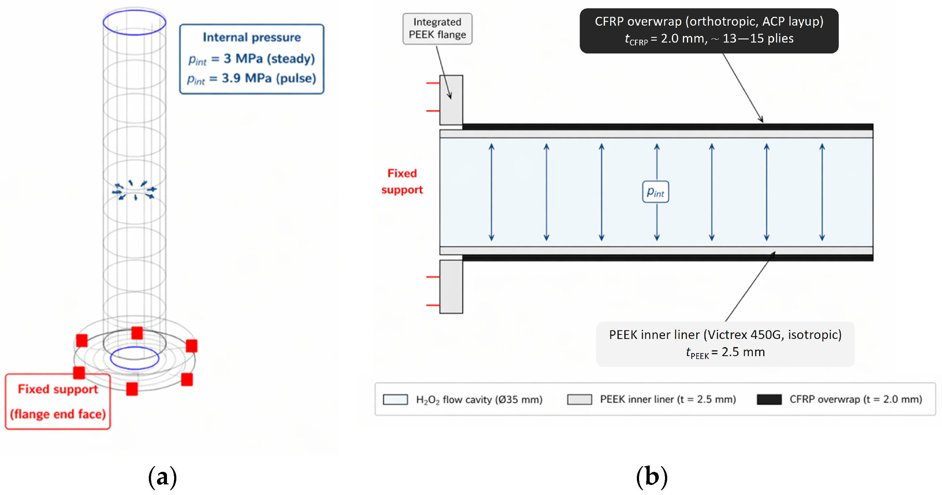
Figure A2.
CFD-predicted static pressure distribution on the inner flow surface at 32,000 rpm (maximum 2.79 MPa).
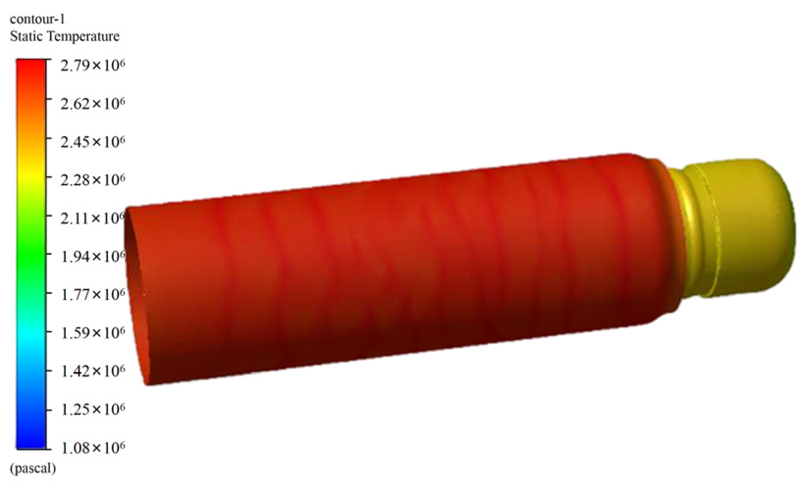
Figure A3.
Fatigue test pressure and temperature histories: (a) Phase 1: Fatigue test pressure versus temperature curve at an ambient temperature of 25 °C; (b) Enlarged view of the curve segment in the 2000~3000 s range in (a); (c) Phase 2: Fatigue test pressure-temperature curve when the ambient temperature is preheated to 90 °C; (d) Enlarged view of the curve segment in the 6600~7600 s time interval in (c); (e) Pressure-temperature curve for fatigue testing under cyclic environmental temperatures ranging from 25°C to 95 °C; (f) Enlarged view of the curve segment in the 4000~5000 s time interval in (e).
References
- Solda, N.; Lentini, D. Opportunities for a Liquid Rocket Feed System Based on Electric Pumps. J. Propuls. Power 2008, 24, 1340–1346. [Google Scholar] [CrossRef] [Scilit]
- Waxenegger-Wilfing, G.; Deeken, J.; Santos Hahn, R.H. Studies on electric pump-fed liquid rocket engines for micro-launchers. In Space Propulsion 2018 Conference Proceedings; ESA/3AF; Institute of Space Propulsion: Hardthausen, Germany, 2018. [Google Scholar]
- Kwak, H.-D.; Kwon, S.; Choi, C.-H. Performance assessment of electrically driven pump-fed LOX/kerosene cycle rocket engine: Comparison with gas generator cycle. Aerosp. Sci. Technol. 2018, 77, 67–82. [Google Scholar] [CrossRef] [Scilit]
- Borisavljevic, A.; Polinder, H.; Ferreira, J.A. Enclosure design for a high-speed permanent magnet rotor. IEEE Trans. Ind. Electron. 2014, 61, 1437–1446. [Google Scholar]
- Dubas, F.; Rahideh, A. Two-Dimensional Analytical Permanent-Magnet Eddy-Current Loss Calculations in Slotless PMSM Equipped with Surface-Inset Magnets. IEEE Trans. Magn. 2014, 50, 54–73. [Google Scholar] [CrossRef] [Scilit]
- Shen, J.-X.; Hao, H.; Jin, M.-J.; Yuan, C. Reduction of Rotor Eddy Current Loss in High Speed PM Brushless Machines by Grooving Retaining Sleeve. IEEE Trans. Magn. 2013, 49, 3973–3976. [Google Scholar] [CrossRef] [Scilit]
- Yon, J.M.; Mellor, P.H.; Wrobel, R.; Booker, J.D.; Burrow, S.G. Analysis of Semipermeable Containment Sleeve Technology for High-Speed Permanent Magnet Machines. IEEE Trans. Energy Convers. 2012, 27, 646–653. [Google Scholar] [CrossRef] [Scilit]
- Gieras, J.F. Advancements in Electric Machines; Springer: Dordrecht, The Netherlands, 2010; Volume 10, p. 1007. [Google Scholar]
- Li, S.; Wang, K.; Zhu, W.; Peng, Y.; Ahzi, S.; Chinesta, F. Investigating the mechanical properties of PEEK/CF composites in melting and solid states during in situ consolidation. Compos. Commun. 2022, 34, 101247. [Google Scholar]
- Hu, Y.; Li, Y.; Cai, C.; Wu, X.; Zheng, Z.; Duan, Y.; Zhai, J. Degradation mechanism of carbon fiber reinforced epoxy composites exposed to combined chemical and thermal environments. Polym. Compos. 2019, 40, 4510–4522. [Google Scholar]
- Mehdikhani, M.; Gorbatikh, L.; Verpoest, I.; Stepan, V.L. Voids in fiber-reinforced polymer composites: A review on their formation, characteristics, and effects on mechanical performance. J. Compos. Mater. 2019, 53, 1579–1669. [Google Scholar] [CrossRef] [Scilit]
- Starkova, O.; Gagani, A.I.; Karl, C.W.; Rocha, I.B.C.M.; Burlakovs, J.; Krauklis, A.E. Modelling of environmental ageing of polymers and polymer composites—Durability prediction methods. Polymers 2022, 14, 907. [Google Scholar] [CrossRef] [Scilit]
- Venkatachalam, S.; Murthy, H. Damage characterization and fatigue modeling of CFRP subjected to cyclic loading. Compos. Struct. 2018, 202, 1069–1077. [Google Scholar] [CrossRef] [Scilit]
- Kurtz, S.M.; Devine, J.N. PEEK biomaterials in trauma, orthopedic, and spinal implants. Biomaterials 2007, 28, 4845–4869. [Google Scholar] [CrossRef] [Scilit]
- Gao, S.-L.; Kim, J.-K. Cooling rate influences in carbon fibre/PEEK composites. Part 1. Crystallinity and interface adhesion. Compos. Part A Appl. Sci. Manuf. 2000, 31, 517–530. [Google Scholar] [CrossRef] [Scilit]
- Muhammad, A.K.; Mitschang, P.; Schledjewski, R. Identification of some optimal parameters to achieve higher laminate quality through tape placement process. Adv. Polym. Technol. 2010, 29, 98–111. [Google Scholar] [CrossRef] [Scilit]
- Flaconneche, B.; Martin, J.; Klopffer, M.H. Permeability, Diffusion and Solubility of Gases in Polyethylene, Polyamide 11 and Poly (Vinylidene Fluoride). Oil Gas. Sci. Technol. 2001, 56, 261–278. [Google Scholar] [CrossRef] [Scilit]
- Ventura, M.; Wernimont, E.; Heister, S.; Yuan, S. Rocket Grade Hydrogen Peroxide (RGHP) for use in Propulsion and Power Devices—Historical Discussion of Hazards. In Proceedings of the 43rd AIAA/ASME/SAE/ASEE Joint Propulsion Conference & Exhibit, Cincinnati, OH, USA, 8–11 July 2007. [Google Scholar]
- Simanjuntak, T.P.H.; Andika, M.G.; Wargadipura, A.H.S.; Wahyudi, T.; Rohman, S.; Kalembang, E.; Roseno, S.; Masmui Kurniawati, F.; Budiyanto, D. Microstructural Damage Characterization in Various CFRP Laminate Configurations Subjected to Fatigue Loading Using Micro-Computed Tomography (Micro- CT) and Scanning Electron Microscopy (SEM). Polym. Compos. 2026, 47, 7034–7048. [Google Scholar] [CrossRef] [Scilit]
- Zheng, T.; Liu, Z.; Yin, Y.; Gao, Q. Characterization of early fatigue damage in CFRP unidirectional laminates based on Micro-CT. Polym. Compos. 2024, 46, 3755–3769. [Google Scholar]
- Pakravan, A.; Taheri-Behrooz, F. Fatigue life simulation of the impacted carbon/epoxy composite laminates. Compos. Part A Appl. Sci. Manuf. 2024, 181, 108112. [Google Scholar] [CrossRef] [Scilit]
- Barbosa, A.Q.; Da Silva, L.F.M.; Abenojar, J.; Del Real, J.C.; Paiva, R.M.M.; Öchsner, A. Kinetic analysis and characterization of an epoxy/cork adhesive. Thermochim. Acta 2015, 604, 52–60. [Google Scholar] [CrossRef] [Scilit]
- Ordu, M.; Der, O. Polymeric Materials Selection for Flexible Pulsating Heat Pipe Manufacturing Using a Comparative Hybrid MCDM Approach. Polymers 2023, 15, 2933. [Google Scholar] [CrossRef] [Scilit]
- Sotiria, D.; Eleni, S.; Isidoros, I. A decision-making strategy for selection of FDM-based additively manufactured thermoplastics for industrial applications based on material attributes. Sustain. Futur. 2025, 9, 100640. [Google Scholar]
- Dupont De Nemours Inc. Vespel® SP-1 Polyimide Standard Parts—Product Datasheet; Dupont De Nemours Inc.: Wilmington, DE, USA, 2020. [Google Scholar]
- Ensinger Gmbh. TECAFLON PTFE Natural—Product Data Sheet; Ensinger Gmbh: Nufringen, Germany, 2026. [Google Scholar]
- Victrex Plc. VICTREX™ PEEK 450G Product Data Sheet; Victrex Plc: Thornton Cleveleys, UK, 2026. [Google Scholar]
- Rae, P.J.; Brown, E.N.; Orler, E.B. The mechanical properties of poly(ether-ether-ketone) (PEEK) with emphasis on the large compressive strain response. Polymer 2007, 48, 598–615. [Google Scholar] [CrossRef] [Scilit]
- Air, A.; Shamsuddoha, M.; Prusty, B.G. A review of Type V composite pressure vessels and automated fibre placement based manufacturing. Compos. Part B 2023, 253, 110573. [Google Scholar] [CrossRef] [Scilit]
- Neto, E.S.B.; Chludzinski, M.; Roese, P.B.; Fonseca, J.S.O.; Amico, S.C.; Ferreira, C.A. Experimental and numerical analysis of a LLDPE/HDPE liner for a composite pressure vessel. Polym. Test. 2011, 30, 693–700. [Google Scholar] [CrossRef] [Scilit]
- Azeem, M.; Ya, H.H.; Alam, M.A.; Kumar, M.; Stabla, P.; Smolnicki, M.; Gemi, L.; Khan, R.; Ahmed, T.; Ma, Q.; et al. Application of Filament Winding Technology in Composite Pressure Vessels and Challenges: A Review. J. Energy Storage 2022, 49, 103468. [Google Scholar] [CrossRef] [Scilit]
- Choupin, T.; Fayolle, B.; Régnier, G.; Paris, C.; Cinquin, J.; Brulé, B. Isothermal crystallization kinetic modeling of poly(etherketoneketone) (PEKK) copolymer. Polymer 2017, 111, 73–82. [Google Scholar] [CrossRef] [Scilit]
- Fereidouni, M.; Suong, V.H. In-situ consolidation of thermoplastic composites by automated fiber placement: Characterization of defects. J. Thermoplast. Compos. Mater. 2025, 38, 471–511. [Google Scholar] [CrossRef] [Scilit] [PubMed]
- Bogetti, T.A.; Gillespie, J.W., Jr. Process-induced stress and deformation in thick-section thermoset composite laminates. J. Compos. Mater. 1992, 26, 626–660. [Google Scholar] [CrossRef] [Scilit]
- Chen, F.; Ou, H.; Lu, B.; Long, H. A constitutive model of polyether-ether-ketone (PEEK). J. Mech. Behav. Biomed. Mater. 2016, 53, 427–433. [Google Scholar] [CrossRef] [Scilit]
- Chang, B.; Gu, J.; Long, Z.; Li, Z.; Ruan, S.; Shen, C. Effects of temperature and fiber orientation on the tensile behavior of short carbon fiber reinforced PEEK composites. Polym. Compos. 2021, 42, 597–607. [Google Scholar] [CrossRef] [Scilit]
- GB/T 3354-2014; Test Method for Tensile Properties of Oriented Fiber Reinforced Polymer Matrix Composites Materials. China Standards Press: Beijing, China, 2014.
- Toray Carbon Fibers America. T700S Technical Data Sheet; Toray Carbon Fibers America: Decatur, AL, USA, 2018. [Google Scholar]
- Sankar Reddy, S.; Yuvraj, C.; Prahlada Rao, K. Design, analysis, fabrication and testing of CFRP with CNF composite cylinder for space applications. Int. J. Compos. Mater. 2015, 5, 102–128. [Google Scholar]


Disclaimer/Publisher’s Note: The statements, opinions and data contained in all publications are solely those of the individual author(s) and contributor(s) and not of MDPI and/or the editor(s). MDPI and/or the editor(s) disclaim responsibility for any injury to people or property resulting from any ideas, methods, instructions or products referred to in the content. |
© 2026 by the authors. Licensee MDPI, Basel, Switzerland. This article is an open access article distributed under the terms and conditions of the Creative Commons Attribution (CC BY) license.