


Abstract
This paper investigates the conflicting multiple constraints and safety challenges in humanoid robot teleoperation for nonprehensile transportation tasks. The robot’s complex workspace and high degrees of freedom frequently conflict with highly dynamic task requirements, imposing stringent demands on coordinated motion. To address these issues, this paper proposes a Multiple-Constraint Safety-Critical Control Framework (MC-SCCF) featuring a hierarchical three-layer architecture. The top layer guarantees intrinsic safety against workspace boundaries using a continuously differentiable reachability surrogate model and an improved control barrier function (CBF)-based safe velocity filter for smooth deceleration. The middle layer maps user commands into pose-coupled reference trajectories to ensure task-level object safety, satisfying strict non-slip and non-toppling constraints. The bottom layer utilizes a quadratic programming (QP)-based inverse kinematics solver to achieve self-collision avoidance, coordinated motion, and optimal configuration while strictly enforcing joint and manipulability limits. Simulations and hardware experiments demonstrate that the MC-SCCF achieves real-time, high-precision reachability evaluation and successfully coordinates task dynamics with physical constraints, enhancing operational safety and the human–robot interaction experience.
1. Introduction
Humanoid robots, characterized by their anthropomorphic morphology and versatile motion capabilities, exhibit significant application potential in unstructured environments such as disaster rescue, domestic service, and industrial collaboration. Within these complex scenarios, object transportation is a fundamental and critical task. As an essential mode of operation, nonprehensile transportation demonstrates unique advantages in practical applications [1], making it particularly suitable for objects that are difficult to grasp directly. For instance, during the transfer of hazardous, fragile, or contaminated items, or when carrying food on a tray, nonprehensile transportation achieves object manipulation by strategically leveraging friction, gravity, and inertial forces. This approach not only reduces the internal forces exerted on the objects, thereby lowering the risk of damage, but also enables the simultaneous transportation of multiple objects, significantly improving operational efficiency.
However, such tasks impose stringent requirements on the dynamic coordination capabilities of the system. Given the current limitations in the decision-making capabilities of fully autonomous robots in complex dynamic environments, teleoperation, as a human-in-the-loop solution, integrates the cognitive adaptability of human operators with the physical manipulation capabilities of robots. Consequently, it has emerged as the prominent approach for executing such complex transportation tasks.
Although teleoperation enables robots to exploit human cognitive capabilities in complex environments, transferring nonprehensile transportation tasks to humanoid robot platforms still poses major challenges to control system design. On the one hand, nonprehensile transportation relies on friction, gravity, and inertial forces to maintain object stability. The object must be prevented from slipping or toppling during motion, which imposes strict coupling among the position, orientation, velocity, and acceleration of the end-effector trajectory. In particular, during highly dynamic teleoperation, the object orientation is highly sensitive to variations in linear and angular accelerations. Any abrupt change or relaxation of constraints may directly lead to task failure. On the other hand, the upper body of a humanoid robot has a highly redundant dual-arm structure. Intrinsic constraints, including dual-arm coordination, joint limits, singularity avoidance, self-collision avoidance, and workspace boundaries, coexist and become dynamically coupled as the robot configuration changes.
Traditional robot safety control methods usually assign high priority to constraints related to the robot’s intrinsic safety, while treating task constraints as low-priority or soft constraints [2,3,4,5]. This design can prioritize the prevention of dangerous robot motions in general manipulation tasks. For nonprehensile transportation, however, object non-slipping, non-toppling, trajectory smoothness, and orientation stability are not secondary objectives that can be arbitrarily relaxed. Instead, they are hard conditions that determine whether the task can be completed. Thus, if the conventional priority allocation is directly adopted, and constraints such as workspace boundaries, joint limits, and singularity avoidance are combined with object dynamic constraints in a single optimization problem, or if their conflicts are handled only by weight tuning, two problems often arise. First, the abrupt activation of robot intrinsic constraints may induce acceleration discontinuities at the end-effectors, thereby disrupting object balance. Second, excessively conservative restrictions on robot motion may be imposed to maintain object stability, which greatly compresses the effective operational workspace.
When a humanoid robot executes the task, workspace boundary constraints are particularly prone to conflicts with task dynamic constraints. Workspace boundary evaluation for dual-arm coordinated tasks is fundamentally different from that in single-arm scenarios. Because the dual end-effectors must maintain a relative pose relationship and the two kinematic chains share a movable waist joint, even if a target pose lies within the single-arm reachable regions of the left and right arms separately, there is no guarantee that a common waist configuration exists such that both arms can reach their target poses simultaneously. Therefore, the workspace boundary in nonprehensile transportation is not merely a geometric envelope approached by a single end-effector. Instead, it results from the combined effects of dual-arm cooperative reachability, waist configuration, object orientation, and task constraints.
To address these issues, the core idea of this paper is to hierarchically decouple multiple constraints according to their physical roles and conflict relationships in nonprehensile transportation. Specifically, the constraints are divided into three levels. The top layer handles the cooperative workspace boundary constraints of the robot. The middle layer addresses task dynamic constraints, such as object non-slipping and non-toppling. The bottom layer processes intrinsic kinematic constraints of the robot, including dual-arm coordination, trajectory tracking, singularity avoidance, self-collision avoidance, and joint limits. This hierarchy is not a simple priority setting that places robot safety above task constraints. Instead, it reorganizes the order in which constraints take effect for nonprehensile transportation. The top layer first constrains user inputs through a safe velocity filter, allowing the system to decelerate smoothly with controlled acceleration before approaching the cooperative workspace boundary. This prevents direct conflicts between workspace boundary constraints and the object dynamic constraints handled in the middle layer. Based on the safe velocity output from the top layer, the middle layer generates pose-coupled trajectories that satisfy multi-object non-slipping and non-toppling constraints. The bottom layer then handles the remaining kinematic constraints, including dual-arm coordinated motion, self-collision avoidance, singularity avoidance, and configuration optimization within the null space of the task trajectory.
In this framework, the top-level safe velocity filter plays a key role in decoupling constraints. Unlike conventional hard boundary truncation methods, the proposed safe velocity filter based on an improved CBF explicitly introduces a maximum acceleration constraint during deceleration. This allows the robot to achieve smooth and controlled deceleration when approaching workspace boundaries, thereby reducing the risk of abrupt orientation changes and object toppling. Compared with conventional linear CBFs, this method avoids the tradeoff between overly conservative deceleration and excessive acceleration peaks at the activation instant. It maintains a larger effective operational workspace while keeping the object forces smooth during nonprehensile transportation. In addition, to address the difficulty of analytically describing the cooperative workspace boundaries of the robot, this paper designs a reachability determination method based on a differentiable reachability surrogate model. This method estimates the cooperative workspace boundary distance along the current motion direction in real time, providing boundary information for the top-level velocity filter.
Based on the above hierarchical decoupling mechanism, the bottom-level controller no longer needs to simultaneously handle the direct conflict between workspace boundary constraints and object dynamic constraints. Instead, it can track the object trajectory and achieve dual-arm coordinated motion through quadratic programming while satisfying the task trajectory generated by the middle layer. Self-collision avoidance, singularity avoidance, joint limits, and configuration optimization are then realized in the task null space. Accordingly, this paper constructs a Multiple-Constraint Safety-Critical Control Framework (MC-SCCF) for humanoid robot teleoperation in nonprehensile transportation, as shown in Figure 1. The proposed framework enables coordinated processing of workspace boundary constraints, task dynamic constraints, and intrinsic kinematic constraints of the robot.
Figure 1.
Block diagram of the proposed MC-SCCF.
The primary contributions of this paper are summarized as follows:
- A MC-SCCF is proposed for humanoid robot nonprehensile transportation. Different from conventional priority-based designs that simply place robot intrinsic safety constraints above task constraints, this paper decouples multiple constraints into three hierarchical levels according to the conflict relationships among workspace boundary constraints, object dynamic constraints, and intrinsic kinematic constraints of the robot. The top layer is responsible for the intrinsic safety of the robot under workspace constraints. It handles cooperative workspace boundaries through a safe velocity filter and isolates the direct impact of boundary constraints on task dynamic constraints. The middle layer generates pose-coupled reference trajectories that satisfy non-slipping and non-toppling requirements, thereby enforcing object dynamic constraints and ensuring task safety. The bottom layer handles the remaining kinematic constraints and task execution. While satisfying joint and manipulability constraints, it achieves self-collision avoidance, coordinated motion, and configuration optimization. This framework provides a systematic method for coordinating multiple hard constraints in humanoid robot nonprehensile transportation.
- A top-level safe velocity modulation strategy is proposed to handle the workspace boundaries of humanoid robots. To address the acceleration discontinuities caused by conventional hard boundary truncation and the tradeoff between conservative deceleration and orientation jitter in conventional linear CBFs, this paper designs an improved CBF based on acceleration constraints. This method enables the robot to decelerate smoothly with controlled acceleration when approaching workspace boundaries, thereby keeping the object forces and orientation variations more stable. In addition, to address the difficulty of analytically describing the cooperative workspace boundaries of humanoid dual arms, this paper proposes a boundary determination method based on a differentiable reachability surrogate model, which enables real-time estimation of the cooperative workspace boundary distance.
- The effectiveness of the proposed MC-SCCF is validated through experiments. Teleoperation experiments of multi-object nonprehensile transportation are designed and conducted on a physical humanoid robot platform. The experimental results demonstrate that this multilayered control framework can simultaneously guarantee the task dynamic constraints and the robot’s intrinsic kinematic constraints, thereby enhancing operational safety and smoothness while improving the human–robot interaction experience.
2. Related Work
2.1. Determination of Workspace Boundaries and Target Reachability Analysis
When humanoid robots execute nonprehensile transportation tasks, accurately evaluating the reachability of target poses and determining workspace boundaries are prerequisites for ensuring system safety and task success [6,7]. Traditional methods for determining workspace boundaries primarily include the Monte Carlo method [8], geometric envelope scanning [9], and numerical tracking methods based on Jacobian matrix singularity analysis [10,11]. These methods can macroscopically delineate the furthest theoretical physical boundaries reachable by the robot’s end-effectors [12]. For dual-arm nonprehensile transportation tasks, merely obtaining a rough outer envelope surface is insufficient [13,14]. During practical teleoperation, the robot frequently needs to perform precise pose adjustments near the workspace boundaries. In such cases, accurately evaluating the reachability of specific target poses in real time becomes critical.
Reachability evaluation for dual-arm coordinated tasks is subject to relative pose constraints, which restrict the effective workspace. Furthermore, because the dual arms of a humanoid robot share a movable waist joint, the two kinematic chains exhibit highly coupled characteristics. Every movement of the waist simultaneously affects the workspaces of both arms [15,16]. Currently, there are three primary strategies for evaluating target pose reachability. The first category is optimization-based numerical inverse kinematics, such as whole-body control (WBC) methods [17,18,19]. Although this approach can handle complex dual-arm coordination and waist coupling constraints through nonlinear optimization, its solution process depends on the selection of initial values [20]. If used solely for preliminary reachability queries, this method is not only time-consuming but also prone to falling into local minima, leading to misjudgments [21,22,23,24]. The second category comprises algebraic or geometric analytical methods [25]. These methods exhibit fast computational speeds but typically require the robot to possess specific structures, such as a spherical wrist, to achieve kinematic decoupling. Therefore, they are difficult to generalize directly to the highly redundant upper-body systems of humanoid robots [26]. The third category is the currently widely applied data-driven reachability map method [27,28,29,30,31]. While this method achieves fast online querying by calculating and recording the reachability probability within Cartesian space voxels offline, extending it to dual-arm coupled configurations with a waist joint requires traversing every possible waist configuration for querying, which is computationally inefficient in practical applications [32,33].
In summary, when dealing with the highly coupled dual-arm systems of humanoid robots with a waist, existing reachability analysis methods frequently fall into a conflict between computational efficiency and evaluation accuracy, making it difficult to meet the demands of teleoperation tasks. Designing a real-time and accurate method for evaluating the reachability of cooperative dual-arm workspace boundaries remains a challenge in current teleoperation control frameworks.
2.2. Robot Intrinsic Constraint Processing Methods in Teleoperation
In humanoid robot teleoperation, ensuring the intrinsic safety of the robot (e.g., joint limits, self-collision avoidance, and singularity avoidance) is the foundation for stable system operation. Current solutions are primarily divided into two categories: feedback-based assistive guidance and optimization-based local autonomous control.
Feedback-based assistive guidance aims to enhance the operator’s perception of the environment and constraints through multimodal information, thereby guiding the operator to make correct decisions. Regarding force feedback, virtual fixtures are widely applied to prevent the manipulator from colliding with obstacles and to avoid self-collisions by establishing repulsive force fields around obstacles and between robot links [34,35]. Metrics related to robot reachability maps and manipulability are utilized to establish attractive, repulsive, or damping forces. These forces guide the operator to actively avoid robot singular configurations and stay clear of dangerous areas such as workspace boundaries [36,37,38,39]. In addition, tactile feedback conveys the contact state with the interacting object through vibration or electrical stimulation, or it alerts the operator to dangerous situations using stimuli of varying intensities and frequencies as an alternative to force feedback [40,41]. Visual feedback provides the operator with a global perspective through the integration of digital model simulations, predicted trajectories, AR/VR systems, and multimodal information, intuitively presenting potential collision risks to the operator in a feedforward manner [42,43].
Force and tactile feedback impose stringent requirements on hardware equipment, communication latency, and force algorithms. Inappropriate force guidance may interfere with the operator’s normal tasks. More importantly, feedback-based assistance merely serves as a cue. Ultimate safety still depends on the operator’s experience and reaction speed, making it difficult to provide deterministic safety guarantees during highly dynamic interactions.
In contrast, optimization-based local autonomous control has become the current mainstream trend. In this approach, algorithms directly manage constraint processing. Its core idea is to model the control problem as a constrained optimization problem, typically QP. Within this framework, joint limits, velocity boundaries, and obstacle avoidance requirements are transformed into mathematical inequality constraints, ensuring that the generated control commands lie strictly within the feasible region [4,5,44]. Recently, control barrier functions (CBFs) and control Lyapunov functions (CLFs), serving as effective tools for constructing safe sets and ensuring stability [45,46,47], are frequently integrated into optimization frameworks to enhance performance.
In teleoperation research focusing on nonprehensile transportation, some researchers have attempted to combine these two approaches. Selvaggio et al. [48] proposed a shared control architecture that introduces friction cone constraints into the QP to handle object dynamics while simultaneously generating virtual forces based on position deviations to guide the user. Muchacho et al. [49,50] processed task constraints via model predictive control (MPC) and indicated the robot’s intrinsic motion limitations through force feedback. In our previous work [51,52], we proposed a shared teleoperation framework based on virtual object model predictive control (VO-MPC). This method resolves the algorithm’s dependence on precise object parameters and enhances the system’s robustness to unknown objects by transforming complex multi-object constraints into the boundary constraints of a single virtual offset object.
Nevertheless, the aforementioned studies are primarily based on single-manipulator systems, whose kinematic constraints are relatively simple. Directly migrating these methods to humanoid robot nonprehensile transportation tasks presents difficulties. The upper-body system of a humanoid robot possesses high kinematic redundancy, resulting in complex intrinsic kinematic constraints. Concurrently, nonprehensile transportation tasks involve strict dynamic constraints. A coupling relationship exists between the object’s position and orientation trajectories, and the object’s balance is highly sensitive to acceleration and pose. These two types of constraints frequently conflict during complex motions. Achieving compatibility among multiple hard constraints through weight allocation or soft constraint processing is difficult. Therefore, existing research has yet to resolve this challenge: how to construct a hierarchically decoupled control framework that achieves the unified integration of task execution and system safety while satisfying multiple physical constraints.
3. Safe Velocity Modulation Mechanism
Within the proposed MC-SCCF, the primary objective of the top layer is to transform the desired velocities input by the operator into safe velocity commands. To address workspace boundary constraints, this section formulates a safe velocity filter that is minimally invasive to the operator’s intent. This filter utilizes an improved CBF as the optimization constraint. The improved CBF employs a piecewise function, enabling smooth, acceleration-controlled deceleration as the manipulator’s end-effector approaches the workspace boundaries. Furthermore, to resolve the challenges of target reachability evaluation and workspace boundary distance calculation, a boundary evaluation method based on a differentiable reachability surrogate model is developed.
3.1. Safe Velocity Filter Design
Let denote the desired velocity command input by the operator. and represent the position and velocity of the safe velocity filter output of the transported object in the task space, respectively, and denotes the actual position of the object. We formulate the following real-time QP problem to achieve safety filtering by solving for the optimal control input , which represents the desired acceleration :
In this formulation, represents the signed distance from the object to the workspace boundary along the direction of the current desired velocity. Within the proposed multilayer optimization framework, the middle and bottom layers ensure that tracks in real time. The term denotes the model relating the end-effector velocity to the input. The core of this framework is the inequality constraint , which dictates the braking characteristics of the system as it approaches the boundaries.
The definition of is further clarified as follows. Since the workspace boundary is generally a complex surface and the interior of the workspace is connected, is defined as the boundary distance along the current motion direction. Specifically, a ray is constructed from the current position of the object along its current velocity direction. This ray may intersect the workspace boundary at one or more points, and is defined as the distance from the current object position to the nearest intersection. Therefore, when the velocity direction of the object remains unchanged, the intersection between the ray and the workspace boundary is fixed, and , where denotes the actual velocity of the object. In this case, continuously decreases as the object moves. Since the object always remains inside the workspace, is always satisfied. When the object position or velocity direction changes, the ray determined by the current position and velocity direction also changes, and its intersection with the workspace boundary changes accordingly. Thus, is redefined with respect to the current motion direction. Under this definition, does not describe whether the object moves away from a fixed workspace boundary. When the velocity direction changes, what changes is the workspace boundary approached by the current motion.
3.2. Improved CBF Based on Acceleration Constraints
In handling workspace boundary constraints, CBFs provide an effective mechanism for ensuring forward invariance by modulating the system state derivative. For a given safe set , the function in conventional CBF design is typically chosen as a linear class function, , where is a constant. When the barrier constraint is activated, the system velocity toward the boundary decays exponentially and asymptotically reaches zero at the boundary.
However, this linear class function possesses limitations in nonprehensile transportation tasks. In such tasks, the object’s orientation is coupled with its acceleration. When an object approaches the boundary at a certain velocity, the instantaneous activation of the CBF constraint can generate a large acceleration peak, with an acceleration norm of , leading to the object tilting and orientation jitter. Reducing to mitigate orientation jitter would cause the robot to restrict its velocity at a significant distance from the boundary, thereby compressing the effective workspace and reducing operational efficiency.
To address this, we design an improved CBF based on acceleration constraints, aimed at ensuring the controllability and boundedness of the object’s orientation during deceleration. The improved class function is defined as follows:
where denotes the maximum allowable acceleration during the deceleration phase, and is the switching threshold used to smoothly connect the piecewise function. To ensure constraint continuity and avoid step signals at the switching point , the gain must satisfy the matching condition .
Proposition 1.
Consider the system state in the safe set . If the control input always satisfies the improved control barrier function constraint , where
and , then the safe set is forward invariant.
Proof.
When , we have . Since , this segment is strictly increasing and satisfies . □
When , we have . Since , its derivative is . Thus, this segment is also strictly increasing.
At the switching point , the left and right limits of the two segments and their derivatives satisfy
Therefore, is continuously differentiable for . It also satisfies , and holds for any .
Consider the comparison system:
Since and for any , cannot cross from the nonnegative half-axis to the negative half-axis. According to the comparison lemma, we have
Thus, as long as the initial state lies in the safe set, the system trajectory remains in the safe set, and the workspace boundary is not violated. This completes the proof.
Furthermore, when the object approaches the workspace boundary and the barrier constraint is active, we have
Therefore, the acceleration magnitude during deceleration can be written as
When , we obtain .
When , we obtain .
Thus, throughout the boundary-approaching process, the acceleration during deceleration always satisfies .
The improved class function partitions the boundary approach process into a constant deceleration phase and an exponential convergence phase:
Constant Deceleration Phase (): When , the system undergoes constant deceleration subject to the constraint of .
Exponential Convergence Phase (): When , the constraint switches to the linear CBF form, and the system velocity decays exponentially.
Assuming a constant velocity direction for the object, when , the object undergoes two stages of deceleration, and the total deceleration distance is:
When , the deceleration process remains in the exponential convergence phase, and the deceleration distance is:
By introducing a maximum acceleration constraint, the improved CBF ensures stable forces on the object, with controlled acceleration and pose during deceleration. As the robot nears the boundary, the switch to the linear CBF ensures smoother deceleration. This leverages the asymptotic convergence of the exponential function to eliminate chattering phenomena as the velocity approaches zero, ensuring the robot stops smoothly at the boundary.
3.3. Workspace Boundary Determination
To achieve velocity modulation, the system must calculate the distance from the current position to the workspace boundary in real time. Under the constraint of the CBF, the object will stop at the workspace boundary. Therefore, is defined as the Euclidean distance between the current position and the furthest reachable position in the current velocity direction with a static orientation.
During dual-arm cooperative tasks, workspace reachability can be defined as whether there exists a waist configuration that makes the target poses of both end-effectors simultaneously reachable. Querying by traversing all waist configurations cannot satisfy real-time requirements. Hence, we design a target reachability evaluation method utilizing a differentiable reachability surrogate model. The reachability of target points is iteratively determined using the bisection method to achieve a fast and accurate approximation of the workspace boundary.
3.3.1. Reachability Determination
In dual-arm cooperative tasks, the reachability of target poses is restricted not only by kinematic coupling but also by the robot’s self-collision constraints. Therefore, prior to conducting the kinematic reachability search, the shortest distance between the bounding volumes of the dual-arm end-effectors and the bounding volume of the robot base at the target pose is calculated. If a collision occurs, the target is directly determined as unreachable. When no collision exists, reachability determination at the kinematic level is performed.
Considering the kinematic independence of the two arms relative to their respective shoulder bases, we reduce the dimensionality of the problem. First, the true discrete reachability maps of both arms relative to the shoulder coordinate systems are established, and a continuously differentiable reachability surrogate model is trained accordingly. Subsequently, utilizing the gradient information of the surrogate model, the optimal waist configuration is determined to maximize the reachability of the dual-arm target positions. Finally, according to the optimal configuration, the reachability of the target pose is determined within the true reachability map. The reachability determination process is summarized in Algorithm 1.
The discrete reachability map divides the space into three-dimensional voxels with an edge length of , and the centroid of each voxel represents its position. The selection of the grid resolution requires a tradeoff between storage cost and determination accuracy. An excessively large introduces notable discretization errors, leading to inaccurate boundary determination. In contrast, an excessively small causes the number of voxels to increase cubically, which increases both the storage burden and the size of the training dataset. Considering the robot scale, task accuracy requirements, and storage cost, is set to 0.05 m.
The axis-angle representation is used to specify orientations. Specifically, unit rotational axes uniformly distributed in space are defined, and rotational angles uniformly distributed within are specified. These axes and angles jointly constitute orientations. At the position of each voxel, the inverse kinematics for all orientations are calculated sequentially. All poses are encoded, and the existence of their inverse kinematic solutions is recorded. Compared with uniform longitude-latitude sampling, spherical sampling ensures an approximately uniform distribution of directions on the sphere and avoids statistical bias caused by excessive sampling density near the polar regions. In this section, and are used, meaning that each voxel position covers 720 discrete orientations.
The reachability of position is defined as:
where denotes the number of existing inverse kinematic solutions at this position. Let and denote the positions of the left arm end-effector relative to the left shoulder base and the right arm end-effector relative to the right shoulder base, respectively. and represent the reachability maps of the left and right arms, respectively. The reachability maps of the dual arms are illustrated in Figure 2.
Figure 2.
Dual-arm reachability maps of the custom-built humanoid robot platform.
We employ a fully connected neural network (FCNN) to train the reachability surrogate model, which learns the nonlinear mapping from the end-effector position to the reachability index , where . The input is the three-dimensional end-effector position expressed in the corresponding shoulder base frame, and the output is the continuous reachability prediction at that position. In each shoulder coordinate frame, the original sampling space is discretized into three-dimensional grid points, where , given that the manipulator length is 1 m. Therefore, each single-arm reachability dataset contains 68,921 sampled points.
Before training, the robot joints are set to the zero configuration. The end-effector positions in the left- and right-arm reachability maps are first transformed into their corresponding shoulder base frames. Invalid samples with a reachability index of zero are then removed, and only spatial points with valid inverse kinematic solutions are retained for training. Each sample consists of a three-dimensional end-effector position and the corresponding reachability index. The valid datasets contain 30,757 samples for the left arm and 30,753 samples for the right arm, which are randomly divided into training and validation sets at a ratio of 70% and 30%, respectively.
The FCNN contains three hidden fully connected layers with 256, 128, and 64 neurons, respectively. The Swish activation function is used in all hidden layers, and batch normalization layers are added after the first two hidden layers to improve training stability. The network is trained using the Adam optimizer with a maximum of 150 epochs, a mini-batch size of 512, and an initial learning rate of 0.001. A piecewise learning-rate decay strategy is adopted, in which the learning rate is reduced by a factor of 0.5 every 30 epochs. During training, L2 regularization, gradient clipping, and validation-based early stopping are applied to reduce the risk of overfitting and improve the generalization capability of the model. After training, the surrogate model provides a continuous fit to the discrete reachability data, with on the test set. This continuously differentiable model supports the subsequent reachability gradient calculation and waist configuration optimization. The fitting results are shown in Figure 3. In the illustrated cross-sections, the fitting error is less than 0.15.
Figure 3.
Fitting results of to . (a–c) depict the fitting results for the cross-sections at , respectively. (d–f) represent the fitting errors for the cross-sections at , respectively. (g–i) illustrate the fitting results for the cross-sections at , respectively. (j–l) denote the fitting errors for the cross-sections at , respectively.
Utilizing this continuously differentiable reachability surrogate model, the gradient of reachability with respect to position, denoted as , can be calculated. This gradient indicates the direction of the steepest increase in reachability. Consequently, the search for the optimal waist configuration is modeled as a gradient-driven iterative optimization process.
For a given waist configuration, the reachability gradient at the target position can be regarded as a virtual attractive force pulling the position toward the direction of increasing reachability. The reaction force of this virtual attractive force , acts on the shoulder base. If the waist joint is set to damping mode, it will move under the influence of toward a configuration that increases the reachability of the target position. The iterative formula for the waist joint angle is defined as:
where is the damping coefficient, and represents the update step size. denotes the Jacobian matrix of the waist joint, with .
The iteration terminates when or the maximum number of iterations, , is reached. Utilizing , the system calculates the exact poses of the dual-arm target poses within their respective shoulder coordinate systems and performs a nearest neighbor query within the true discrete reachability maps. If inverse kinematic solutions exist for the nearest neighbors of both target poses, the target is determined as reachable; otherwise, it is determined as unreachable.
| Algorithm 1: Reachability determination of target pose |
2: Return false 3: End If 4: 5: for do 6: // Step 1: Compute EE positions relative to shoulder frames 7: , 8: // Step 2: Compute Virtual Forces and Map to Waist Joints 9: 10: // Step 3: Enforce joint limits and Update Waist Angle 11: 12: 13: // Step 4: Check Convergence 14: If OR Then 15: 16: Break for 17: End If 18: End for 19: // Step 5: Nearest Neighbor Query 20: , 21: , 22: , 23: // Step 6: Reachability Decision 24: If AND Then 25: Return true 26: Else 27: Return false 28: End If |
3.3.2. Boundary Distance Calculation
The purpose of calculating the distance from the current position to the workspace boundary is to determine whether the CBF constraint needs to be applied to the current motion. Therefore, precise boundary searching is not required at all times. We improve computational efficiency through predictive pruning.
- Predictive Stopping Pose Detection (Pruning Step): First, the system calculates the Predicted Stopping Pose (PSP) based on the current motion state. The PSP is defined as the pose where the object would come to a complete stop along the current velocity direction if the CBF constraint were triggered at the current moment. According to (1) and (2), the position of the PSP is calculated as . The orientation of the PSP is defined as the static orientation of the object. Then, the reachability of the PSP is verified using the method described in Section 3.3.1. If the PSP is determined to be reachable, it indicates that the robot can safely stop within the workspace given its current velocity and braking capability. In this case, the CBF constraint will not be activated, and the calculation of the precise boundary distance is unnecessary.
- Bisection-Based Boundary Approximation (Bisection Search): If the PSP is determined to be unreachable, it implies a risk of boundary violation, and the system initiates a precise search. A bisection search is performed along the ray connecting the current position and the PSP to iteratively sample and determine the reachability of each point. The iteration terminates when the length of the sampling interval is smaller than the spatial resolution of the offline reachability map.
4. Dynamic Constraint Processing Method Based on a Virtual Object
Within the middle layer of the MC-SCCF, the primary objective is to ensure that the transported object (or multiple objects on a tray) does not slip or topple when the robot executes nonprehensile transportation tasks. Nonprehensile transportation relies on contact forces and inertial forces to maintain stability. We adopt the dynamic constraint processing algorithm based on a virtual object proposed in our previous work [51,52]. The core idea of this algorithm is to transform complex multi-object constraints into the constraints of a single virtual offset object, combined with MPC to achieve online trajectory smoothing.
4.1. Construction of Virtual Objects
In nonprehensile transportation systems, the risk of object instability (slipping or toppling) is highly correlated with its relative position on the tray, geometric dimensions, and the friction coefficient of the contact surface. To achieve constraint dimensionality reduction, we extract the limit parameters from multiple real objects on the tray: the minimum base edge length , the maximum height , and the minimum friction coefficient . Two special virtual objects are constructed:
- Virtual reference object O (for trajectory planning): This object is placed at the geometric center of the tray. The controller refers to object O for trajectory planning and ensures continuity of the position. Simultaneously, the center of mass (CoM) coordinate system of O is utilized as the center of rotation of the tray to calculate the orientation. Reference object O and offset object A share the same shape and mass.
- Virtual offset object A (for dynamic constraint analysis): The shape of offset object A is a rectangular prism with a square base, featuring a base edge length of , a height of , and a friction coefficient of . Its mass is concentrated at its eight vertices, with a total mass of 1 kg. The maximum moment of inertia of the offset object is defined as . The specific position of offset object A is arbitrary, provided that the distance between A and O is maximized. The distance between the offset object and the reference object is expressed as , where denotes the maximum radius of the actual tray. Although the offset object is not necessarily located on the physical tray, it can be assumed that the tray is sufficiently large, allowing the offset object to be utilized for constraint calculation.
This configuration renders the offset object more susceptible to slipping and toppling than any real object on the tray. Under any motion state, as long as the offset object remains stable, all real objects on the tray are guaranteed to maintain stability. Therefore, the dynamic constraints of multiple objects are transformed into the constraints of a single offset object.
4.2. Dynamic Constraint Analysis Based on a Virtual Object
In nonprehensile transportation, the system counteracts tangential contact forces by adjusting the tray’s orientation. Thus, the object’s orientation and linear acceleration are highly coupled. During motion, the offset object and the reference object share the identical orientation, angular velocity, and angular acceleration; nevertheless, their linear accelerations differ. To ensure safety, offset object A must simultaneously satisfy the friction cone constraint and the zero moment point (ZMP) constraint. By neglecting high-order minor coupling terms, these two physical constraints can be directly transformed into a restriction on the angular acceleration of reference object O:
where indicates the linear acceleration of the reference object, represents the gravitational acceleration, and .
4.3. Trajectory Smoothing Based on MPC
Input trajectories generated by human operators during teleoperation typically lack high-order continuity. To generate smooth trajectories that strictly satisfy the aforementioned angular acceleration boundaries, we formulated an MPC position controller structured with a cascade of five integrators. The state vector is defined as . Here, denotes the desired position of the reference object, and represents the fifth derivative of . The control objective is to calculate the optimal system input such that tracks , which is output by the top-layer controller detailed in Section 3.
To eliminate the tangential forces exerted on the object, the desired orientation of the tray, denoted by , is entirely determined by the acceleration of the reference object. Its rotational axis and rotational angle are defined as follows:
Successive differentiation of the orientation reveals that the angular acceleration of the reference object is dictated by . The nonlinear angular acceleration limit in (3) can be mapped into real-time upper and lower bounds for the fourth derivative of the position within the MPC state vector:
where and .
The MPC optimization problem is formulated as follows:
In this formulation, denotes the prediction horizon of the controller; represents the desired state output by the top-layer controller, defined as . The equation represents the discretized state-space model. The notation is employed, where and indicate the weight coefficient matrices for the output and input, respectively.
5. Constraints and Optimization Objectives of Inverse Kinematics
This section maps task-space trajectories to the robot’s joint space utilizing a QP-based low-level controller. This approach ensures that the robot strictly satisfies joint limits and manipulability constraints while achieving self-collision avoidance, configuration optimization, and coordinated motion.
Let represent the generalized coordinates of the humanoid robot’s upper-body system, where indicates the degree of freedom (DoF) of the robot, encompassing the waist joint and the joints of the left and right arms. For each end-effector , the relationship between its task-space velocity and the joint velocity is expressed as follows:
where , and denotes the Jacobian matrix.
5.1. Task Constraints
5.1.1. Trajectory Tracking
In nonprehensile transportation tasks, stability is independent of the virtual reference object’s orientation about its Z-axis, which indicates the normal direction of the contact surface. Therefore, we relax the strict tracking requirement for the Z-axis orientation, constraining only the remaining five DoFs. The objective of orientation tracking shifts to aligning the actual Z-axis () of the reference object’s coordinate frame with the desired Z-axis ().
As demonstrated in Figure 4, denotes the world frame, represents the coordinate frame of the virtual reference object, and indicates the Z-axis of the object’s coordinate frame. Similarly, denotes the Z-axis of the desired coordinate frame. A coordinate frame is introduced, which is rigidly attached to , such that , , and .
Figure 4.
Orientation tracking of the virtual reference object.
The orientation of is represented by the rotation matrix . Using XYZ Euler angles, it is expressed as . The orientation deviation Euler angles within are calculated as , where indicates the angle between and , and represents an arbitrary value. The tracking constraint transformed into joint velocities is formulated as:
where indicates the orientation component of . represents the mapping between the XYZ Euler angle rates and the angular velocity vector, defined as:
The tracking constraint for the object position is defined as:
where denotes the position component of , and indicates the position deviation of the object.
5.1.2. Constant Relative Pose of Dual-Arm End-Effectors
Nonprehensile transportation tasks require that the dual-arm end-effectors maintain no relative motion; otherwise, the tray might fall, or the object might slip and lose contact. As a result, the relative pose between the end-effectors must remain constant. Transforming this relative pose constraint into joint velocity constraints yields:
In this formulation, denotes the relative pose of the end-effectors at joint angle , while indicates the initial joint configuration. represents the relative Jacobian matrix, defined as , where indicates the composite Jacobian matrix . Following the methodology in [53], is expressed as:
where () indicates the absolute orientation of the end-effectors, represents the position of the right end-effector relative to the left, and denotes the skew-symmetric matrix of .
5.1.3. Singularity Avoidance
To maintain adequate kinematic dexterity, the robot must continuously avoid singular configurations. Considering that formulating manipulability directly as an optimization objective might conflict with other objectives, we opt to constrain its lower bound. This approach guarantees system flexibility while releasing substantial optimization space. Utilizing a CBF, this requirement is modeled as an inequality constraint to ensure that the manipulability measure consistently remains above a safety threshold :
where , .
5.1.4. Joint Physical Constraints
Let the joint position limits of the robot be denoted as . Considering the control period , the joint position constraints for the subsequent time step can be transformed into velocity constraints at the current moment:
5.2. Optimization Objectives
5.2.1. Self-Collision Avoidance
Employing an artificial potential field (APF) strategy for self-collision avoidance ensures safety during the dual-arm collaboration process [54,55]. Spherical bounding volumes are utilized to approximate the geometric shape of the robot [56,57]. When the minimum Euclidean distance between bounding volumes is less than a safety threshold, a repulsive force is generated along the line connecting their centers:
where indicates the minimum distance between bounding volumes and , represents the safety threshold, is the repulsion gain coefficient, and denotes the unit vector indicating the direction of repulsion.
Assuming the joints possess viscous damping characteristics with a damping coefficient , the desired avoidance velocity induced by the repulsive force is formulated as:
Subsequently, is incorporated into the cost function as the desired velocity of a secondary task, guiding the robot configuration away from self-collision regions.
5.2.2. Waist Joint Regulation
To ensure more anthropomorphic waist motion and prevent the waist from remaining in extreme pitch states for extended periods, an optimization objective is introduced to return the waist pitch joint to its nominal upright position . A negative feedback control law featuring saturation characteristics is designed to calculate the desired velocity of the waist joint:
In this formulation, denotes the regulation gain, while and represent the upper and lower bounds of the saturation velocity, respectively, with typically . The design of this saturation block aims to prevent excessively large regulation velocities from causing disturbances to the primary tasks.
5.3. Inverse Kinematics Solution
Based on the aforementioned formulations, the optimal joint velocity vector is obtained by solving the following problem:
where and indicate the weight matrices for collision avoidance and waist regulation, respectively. The penalty term at the end of the cost function is employed to ensure numerical stability and minimize energy consumption. By solving the aforementioned QP problem, the controller can output safe and reliable joint velocities with millisecond-level real-time performance.
s.t. (5), (6), (7), (8), (9).
6. Simulations
The simulations primarily tested the methods proposed in Section 3. To verify the effectiveness and real-time performance of the proposed MC-SCCF, we conducted systematic evaluation tests in a simulation environment. The humanoid upper-body robot model utilized features 16 DoFs, comprising two 7-DoF spherical–revolute–spherical (SRS) manipulators and a 2-DoF waist. The robot is illustrated in Figure 5. The yellow translucent objects in the figure denote the bounding volumes attached to the robot links for self-collision avoidance. The relevant parameters of the algorithms are listed in Table 1.
Figure 5.
Simulation model of the robot and its bounding volumes.
Table 1.
Algorithm Parameters.
The parameters and in the table are used in the middle-layer task constraint processing module. Here, and denote the base edge length and height of the virtual reference object and the virtual offset object, respectively, and denotes the maximum radius of the tray. In this section, the virtual object is set as a rectangular prism with a base edge length of 5 cm and a height of 25 cm, corresponding to an aspect ratio of 5:1. This setting results in a high center of mass and a small support area, making the object prone to toppling. The friction coefficient is set to 0.15 to simulate low-friction contact conditions. These settings impose stricter task dynamic constraints and are more likely to induce conflicts between the dynamic constraints and other constraints. and are the state error weight and input weight in the trajectory smoother, respectively, which balance trajectory tracking accuracy and trajectory smoothness. The parameters and are used in the top-level safe velocity filter, affecting the convergence rate of the boundary constraint, numerical tolerance, and upper limit on online search iterations, respectively. The relevant parameters are selected through preliminary simulation tests and are validated in hardware experiments, showing that they meet the combined requirements of real-time performance, constraint safety, and smooth velocity modulation.
6.1. Verification of the Reachability Determination Method
To evaluate the reachability determination algorithm based on the differentiable surrogate model, we conduct comparative tests using both the benchmark method and the proposed method.
Benchmark method: For a given dual-arm target pose, after confirming that no interference occurs with the mobile base, all possible configurations within the waist joint limits are traversed at a resolution of 0.5°. For each waist configuration, the analytical inverse kinematic solutions of both arms are solved. Since the employed manipulators have an SRS configuration, analytical inverse kinematic solutions are available. If analytical solutions exist for both arms under any waist configuration, the target pose is determined to be truly reachable. If no solution exists after all waist configurations are traversed, the target pose is determined to be truly unreachable. The results obtained by the benchmark method are used as the ground truth for the reachability of dual-arm target poses. The selection of bounding volumes is shown in Figure 5.
In nonprehensile transportation tasks, a deterministic relative pose exists between the robot’s dual-arm end-effectors and the tray. Instead of directly evaluating the reachability of arbitrary dual-arm target poses, our evaluation strategy involves randomly generating tray poses in space and thereafter deriving the target poses of the dual-arm end-effectors. Accordingly, this approach aligns more closely with practical task requirements.
Specifically, within a spherical space with a radius of 1.5 m centered at the robot’s waist base joint, target poses of trays with varying widths (25 cm to 80 cm) and random orientations are generated. The accuracy of the algorithm is evaluated by comparing its determination results against the aforementioned ground truth. The experimental results are presented in Table 2.
Table 2.
Confusion Matrix for Reachability Determination Results.
The precision of the algorithm is . This indicates that when the algorithm determines a pose as reachable, the probability of the robot reaching it is 97.60%. The overall accuracy of the algorithm is .
The computational efficiency results for the two methods in determining target pose reachability are listed in Table 3. The benchmark method requires traversing the waist configurations and solving the inverse kinematics of both manipulators under each waist configuration. Moreover, its determination depends on the sampled waist configurations. For unreachable targets and some poses close to joint limits, the benchmark method must traverse all waist configurations before producing a result. Therefore, its query time is much higher than that of the proposed method.
Table 3.
Computational Efficiency Results for the Two Methods.
For the proposed method, the average number of iterations required to compute the optimal waist configuration for each reachability query is 8.5, with a standard deviation of ±2.4. The average computation time for a single reachability query is 60 μs, with a standard deviation of ±34 μs. Although the test results cannot guarantee absolute accuracy, an accuracy above 97% is sufficient for practical use. Minor prediction errors can be eliminated in engineering deployment by introducing a static safety margin. The computational efficiency of the algorithm also meets the expected objective, and this computational overhead is sufficiently low to support the real-time control requirements of teleoperation.
6.2. Evaluation of the Workspace Boundary Determination Algorithm
To objectively evaluate the accuracy and computational efficiency of the workspace boundary determination algorithm, the experiment directly employs the bisection search for the workspace boundary (without applying the predictive stopping pose pruning function). The experiment randomly generates initial tray positions and corresponding velocity directions within the workspace. A high-precision search for the true workspace boundary distance is conducted combining the true reachability determination method from Section 5.1 with the bisection method, setting the iteration termination condition to a sampling interval length of less than 1 cm. The true distance is denoted as , while the boundary distance detected by the proposed method is defined as . The detection deviation of the distance determination is defined as . The experimental results are revealed as follows.
The experimental results demonstrate that the proposed method exhibits high precision in estimating the boundary distance. As illustrated in Figure 6a, the determination deviation distribution is relatively even, with a mean of only 2.26 cm and a standard deviation of 1.29 cm. Among the 10,000 random samples, the maximum detection deviation remains within 4.5 cm. This detection deviation is primarily restricted by the grid resolution (5 cm) of the discrete reachability map; thus, improving this resolution can further enhance the determination accuracy. During actual deployment, to completely eliminate the risk of boundary violation, the safety can be guaranteed at the algorithmic level simply by setting the practical safe boundary distance in the control system to the detected distance minus 4.5 cm.
Figure 6.
Experimental results of the workspace boundary determination algorithm. (a) Histogram of determination errors. (b) Histogram of algorithm execution times.
The time consumption distribution histogram in Figure 6b exhibits the high efficiency of this search strategy. The average time for a single workspace boundary detection is 1.18 ms, with a standard deviation of 0.34 ms, and the maximum detection time consistently remains below 2.5 ms. The computational efficiency of this algorithm can fulfill the requirements of real-time control frameworks for most humanoid robots.
6.3. Evaluation of the Safe Velocity Filter
To evaluate the advantages of the proposed acceleration-constrained piecewise CBF, we compare it with two standard linear CBF baseline methods. Both baselines adopt the conventional class function , but with different gains. All other components of the control framework, including the middle-layer trajectory smoothing module and the low-level inverse kinematics controller, remain unchanged. Therefore, this comparison allows the effect of replacing the standard CBF with the proposed improved CBF to be evaluated independently. The parameter settings of the control schemes are listed in Table 4.
Table 4.
Parameters for Different Safe Velocity Filter Schemes.
A dynamic deceleration simulation scenario is designed: the robot’s dual arms support a tray carrying an object and execute linear motion toward the workspace boundary at various constant initial velocities ranging from 0.5 m/s to 0.9 m/s, applying the three aforementioned control schemes respectively. The velocity and orientation of the object are recorded during the experiment, focusing on statistically analyzing the maximum tilt angle and the deceleration distance of the object during motion. The comparative simulation results are exhibited in Figure 7.
Figure 7.
Results of safe velocity filters with three different CBFs. (a) Relationship between the object’s maximum tilt angle during deceleration and the object’s velocity. (b) Relationship between the object’s deceleration distance and the object’s velocity.
Under conventional linear CBF control (CBF 1 and CBF 2), both the maximum tilt angle and the deceleration distance of the object are positively correlated with the object’s velocity. A horizontal comparison of the two conventional schemes reveals that at the same velocity, a smaller value reduces the maximum tilt angle but increases the deceleration distance. This indicates that mitigating orientation jitter during the deceleration phase by decreasing comes at the cost of reducing the robot’s flexibility and operational workspace. This experimental phenomenon is consistent with the analysis presented in Section 3.
When employing the improved CBF scheme, the maximum tilt angle during the deceleration phase no longer exhibits a notable correlation with the velocity. Theoretically, the maximum tilt angle should not vary with the object’s velocity. In practice, due to the trajectory smoothing effect of the middle-layer controller, the maximum tilt angle is influenced by the velocity to a certain extent, which is expected. Nonetheless, compared to the conventional schemes, the improved CBF achieves an effective limitation on the maximum tilt angle of the deceleration orientation, fulfilling the anticipated objective of maintaining a controlled maximum tilt angle during deceleration.
Comparing the results of the improved CBF and CBF 1, at an object velocity of 0.9 m/s, the maximum tilt angles during the deceleration phase are approximately identical. However, regarding the deceleration distance, the improved CBF yields a shorter distance than CBF 1. Comparing the improved CBF with CBF 2, the deceleration distances are roughly equivalent at velocities of 0.5 m/s and 0.6 m/s; in contrast, as the velocity increases, the maximum tilt angle under CBF 2 becomes markedly larger than that under the improved CBF.
As a result, compared to conventional CBFs, the improved method introduces a maximum acceleration constraint and utilizes a piecewise transition, achieving a tradeoff between constrained space and orientation controllability. It is less invasive to user commands when far from the boundary, thereby preserving a larger operational space; meanwhile, when approaching the boundary, the deceleration is smoother with controlled acceleration, effectively mitigating the risk of object toppling.
7. Experiments
7.1. Experimental Platform and Task Setup
To verify the effectiveness of the proposed MC-SCCF in a physical system, this section designs an experiment for a humanoid robot executing a nonprehensile transportation task. The hardware system for teleoperation is illustrated in Figure 8. The experiment utilizes our custom-built dual-arm humanoid robot [58]. Its upper body comprises two 7-DoF SRS anthropomorphic manipulators and 2-DoF (yaw and pitch) head and waist joints, mounted on a tracked mobile base. The experiments in this study solely control the upper body manipulation of the robot, without involving the locomotion of the mobile base.
Figure 8.
Teleoperation hardware system.
The master device employs a CyberSystem hand controller to track the 3D position data of the human wrist, which is mapped to the humanoid robot’s workspace via an incremental Cartesian space mapping. Because the robot features a large workspace, the displacement of the master user is scaled up by a factor of 4 before being mapped to the robot’s workspace. Additionally, the master device is equipped with a foot pedal functioning as a clutch switch. Thus, operators can adjust their arm positions at any time during the task to achieve more comfortable operation.
A computer running Ubuntu 20.04, equipped with an Intel Core i9-9900K CPU and 64 GB of RAM, is utilized to execute the teleoperation controller. The controller is implemented in C++, applying multithreading technology to separate hand controller data acquisition, teleoperation control, and state feedback reception. The data acquisition thread collects user input data from the master device at a frequency of 40 Hz, with a communication latency between the master device and the teleoperation controller strictly below 1 ms. The teleoperation control operates within the planning thread at a control frequency of 20 Hz, and the communication latency between the teleoperation controller and the robot is less than 20 ms. The optimization problem is solved using the open-source qpOASES package. The thread dedicated to receiving robot state feedback processes a 24 Hz video stream and 100 Hz robot joint states.
The experiment requires operators to control the robot via the master device to execute an obstacle-avoidance transportation task. Operators must teleoperate the robot’s dual arms to lift a tray carrying multiple objects from a starting point at the rear left, cross an obstacle directly in front, and ultimately place it smoothly in a target area on the right. The experimental process is demonstrated in Figure 9.
Figure 9.
Robot transportation process. (a) The robot reaches the initial position to begin transportation. (b) Lifting the tray. (c) Elevating the tray. (d) Further elevating to a height sufficient to clear the obstacle. (e) Crossing the obstacle. (f) Completely clearing the obstacle. (g) Lowering the tray. (h) Reaching the target position.
The dimensions of the tray are 560 mm 375 mm 80 mm. 14 objects to be transported are randomly positioned on the tray. These objects comprise common items, including vases, water bottles, wooden blocks, and glassware, with heights ranging from 100 mm to 235 mm, as exhibited in Figure 8. According to the dimensions of the tray and the objects placed on it, the relevant parameters of the middle-layer controller are listed in Table 5. Because objects inevitably slide during motion, fiducial markers are attached to their tops, and a camera is employed to detect their sliding distances. The camera is fixed above the robot platform and is exclusively utilized to detect sliding distances for result analysis; the positions of the objects are practically under open-loop control.
Table 5.
Parameters of the Middle-Layer Controller.
Visual feedback for the operator is provided by the stereo camera on the robot’s head. No global field of view (FoV) is available during the experiment, which is highly typical in practical teleoperation task execution scenarios. The controller provides kinematic simulations, where both the actual and desired configurations of the robot are simultaneously displayed on the simulation interface. Operators can switch perspectives within the simulation interface to obtain an intuitive understanding of the teleoperated robot’s current state.
7.2. Experimental Conditions and Evaluation Metrics
This section defines the following three control modes:
- No-SVF: No Safe Velocity Filter Mode (Hard Boundary Mode). The middle-layer MPC (ensuring multi-object dynamic constraints) and low-level kinematic hard limits are enabled, whereas the top-layer safe velocity filter is deactivated.
- CBF: Linear CBF Mode (Standard CBF Baseline Mode). The middle-layer MPC is enabled, and a conventional linear CBF () is employed at the top layer as the safe velocity filter.
- MC-SCCF: Proposed Multiple-Constraint Safety-Critical Control Framework. The middle-layer MPC is enabled, and the improved CBF proposed in this study is utilized at the top layer (with algorithm parameters identical to those in the Section 6 simulations).
To reduce experimental randomness, a total of 10 subjects were recruited. All participants signed an informed consent form prior to participating in the experiment. During the procedures, exclusively the input trajectories from the subjects operating the hand controller were recorded, strictly excluding any sensitive or privacy-related data. The experimental protocol was approved by the institutional ethics committee (Approval No. HIT-2025013) and conducted in accordance with the Declaration of Helsinki. Among the subjects, one was female and nine were male, with four possessing prior teleoperation experience. All subjects exhibited normal cognitive levels and equipment operation capabilities. Before the experiment commenced, the designers spent 40 min explaining the task to each subject and assisting them in familiarizing themselves with the equipment. For each trial, the initial robot configuration, the placement of the tray, and the arrangement of objects on the tray remained strictly identical. Each subject performed the experiment using the three modes separately, conducting four trials per mode. This yielded a total of 120 experimental trials.
The evaluation metrics encompass three dimensions: task metrics, subjective evaluation metrics, and control performance metrics. The task metrics include the following:
- Task Success Rate: A success is defined as the tray reaching the target position without colliding with obstacles, and without any objects toppling or falling.
- Completion Time (): Timing initiates when the operator lifts the tray and concludes when the tray is placed at the target position.
- Total Object Sliding Distance (): The sum of the sliding distances of all objects on the tray. A shorter sliding distance indicates smoother motion.
- Activation Time Ratio of the Safe Velocity Filter: Calculated as , where denotes the duration for which the filter remains active.
- Number of Pauses During the Task: Operators can adjust the master device to the most optimal operational area during pauses.
Subjective metrics were collected via a 7-point Likert scale, gathering the subjects’ scores on operational intuitiveness, task difficulty, cognitive load (concentration), and operational confidence.
Control performance metrics comprise the robot’s trajectory tracking accuracy, relative pose error between dual-arm end-effectors, manipulability, minimum distance, and computation time. These metrics are primarily utilized to analyze the effectiveness of the low-level controller.
7.3. Experimental Results
7.3.1. Task Metrics
The statistical experimental results under the three modes are demonstrated in Table 6 and Figure 10. Regarding the task success rate, Mode No-SVF achieved 82.5%. The failures were caused by the lack of inverse kinematic solutions leading to emergency stops, as well as the toppling and slipping of objects. This indicates that when facing complex workspace boundaries and multiple dynamic constraints, relying solely on the operator’s intuition is insufficient to maintain the system within the safe region. In contrast, Modes CBF and MC-SCCF, which incorporate the top-layer safe velocity filter, both achieved a 100% success rate. This result intuitively confirms the necessity and effectiveness of the velocity filtering mechanism in evading kinematic boundary violations and preventing task failures.
Table 6.
Success Rates of the Three Control Modes.
Figure 10.
Experimental results under the three control modes. (a) Completion time; (b) total object sliding distance; (c) activation time ratio of the safe velocity filter; (d) number of pauses during the task.
The completion time and the number of pauses intuitively reflect the system’s efficiency and the fluency of human–robot collaboration. Mode MS-SCCF exhibited the optimal comprehensive performance, requiring the shortest task duration (76.8 s) while maintaining the number of pauses at a reasonable level (4.2). In contrast, although Mode CBF simultaneously guaranteed safety, it required the longest task duration (103 s) and the highest number of pauses (6.72). The underlying reason is that the conventional linear CBF is highly conservative and frequently modifies user input commands, causing severe positional mapping deviations between the master and slave devices. The operator’s subjective displacement fails to elicit a response at the slave end, forcing the operator to frequently depress the clutch switch to readjust the master device’s position. This not only increases the operation time but also disrupts the continuity of teleoperation.
The total object sliding distance measures the smoothness of the transportation process. Because touching hard boundaries in Mode No-SVF easily triggers emergency stops and abrupt acceleration changes, the object sliding distance reached 121 mm. In Modes CBF and MC-SCCF, where the top-layer safe velocity filter is enabled, the sliding distance was substantially suppressed (57.8 mm and 60.9 mm, respectively). The sliding distance in Mode CBF was slightly smaller than that in Mode MC-SCCF, as its conservative filtering strategy resulted in a slower overall motion velocity. Nonetheless, while maintaining high efficiency, Mode MS-SCCF still controlled the sliding distance to an optimal level nearly equivalent to that of Mode CBF. This supports the efficacy of the improved CBF in controlling acceleration and smoothness during the deceleration phase.
Regarding the activation time ratio of the safe velocity filter (), Mode MS-SCCF still triggered the safe velocity regulation mechanism for 29.5% of the time. The experimental task is not inherently complex, and the robot possesses a large workspace; nevertheless, operators easily drive the robot near the workspace boundaries. This is primarily attributed to two reasons. First is the configuration mismatch. Human operators have a different kinematic configuration from the robot. Particularly when holding a tray of fixed width with both arms, a closed-loop kinematic chain is formed. Operators cannot maintain a clear perception of the robot’s configuration at all times. Thus, trajectories input by the operator at the master device frequently cause the robot to touch the workspace boundaries at the slave end.
The second vital reason is that teleoperation typically relies on screens or cameras with specific viewing angles, leading to inaccurate depth perception and limited telepresence. When facing unstructured environments, highly conservative operations are often required. For instance, during the experiment, operators could not accurately evaluate the safe clearance between the tray bottom and the obstacle. To evade collision risks, subjects generally preferred conservative obstacle avoidance strategies, such as excessive elevation or excessive retraction, which accordingly made it easier to drive the robot to its extension limits. However, precisely because operators inevitably drive the robot close to the boundaries, the top-layer velocity modulation mechanism proves to be particularly crucial.
7.3.2. Subjective Evaluation Metrics
The statistical results of the Likert scale align closely with the objective data, as demonstrated in Figure 11. The figure illustrates evaluation results across four dimensions: the intuitiveness of the control mode (7 indicates extremely intuitive), the difficulty of the task (7 indicates extremely easy), the cognitive load and concentration (7 indicates extremely effortless), and the confidence in completing similar future tasks (7 indicates highly confident). The means and standard deviations of the subjective evaluation metrics are listed in Table 7.
Figure 11.
Subjective feedback results of the subjects after using the three control modes. Results were compiled using a 7-point Likert scale, where higher scores represent better subjective experiences.
Table 7.
Means and Standard Deviations of Subjective Evaluation Metrics under the Three Control Modes.
Mode No-SVF: Although the task success rate under this mode was relatively low (only 82.5%) and objective metrics indicated a larger object sliding distance, operators generally awarded it the highest score for operational intuitiveness. This is primarily because Mode No-SVF did not introduce the safe velocity filter; accordingly, user input commands could be directly and entirely transformed into the tray’s motion, realizing a what-you-see-is-what-you-get experience. Nonetheless, this mechanism lacking safety protection also resulted in Mode No-SVF receiving the lowest task difficulty score. In assessing confidence for future tasks, the operators’ scores exhibited considerable variance. Operators who assigned low scores believed that without the protection of the top-layer safe velocity filter, the robot was highly prone to touching workspace boundaries during operation, rendering the task more difficult. This group also assigned relatively lower scores for cognitive load (concentration) in Mode No-SVF. In contrast, operators who assigned high scores were more inclined to believe that the superior operational intuitiveness of Mode No-SVF was more conducive to task completion; these high-scoring individuals simultaneously assigned higher scores for concentration.
Mode CBF: Benefiting from the introduction of the conventional linear CBF, the overall evaluation of task difficulty for this mode was easier than that of Mode No-SVF, though the statistical results similarly presented considerable variance. The core reason subjects found it easy was that the algorithm guaranteed safety; the tray would not cross workspace boundaries, thereby avoiding situations without inverse kinematic solutions. However, the reason this mode was perceived as difficult was its poor operational intuitiveness. Due to the conservative filtering mechanism of the conventional CBF, master inputs were frequently suppressed by the system, triggering a notable sluggishness in operation. This unstable mapping of master-slave positions, coupled with the robot’s frequent slow motions, substantially increased the operators’ cognitive load.
Mode MC-SCCF: Integrating all subjective metrics, Mode MS-SCCF provided a superior interaction experience among the tested modes. Subjects required the lowest concentration when executing tasks, indicating that this mode possesses a minimal cognitive load, allowing users to complete the nonprehensile transportation experiment with ease. Furthermore, this mode not only overcame the sluggishness noted in Mode CBF and preserved adequate operational intuitiveness but also provided operators with the highest confidence for completing future tasks. Overall, driven by the MC-SCCF integrated with the improved CBF, Mode MS-SCCF balances system safety and operational intuitiveness, making it the most preferred among the three modes.
7.3.3. Control Performance Metrics
To verify the effectiveness of the low-level controller and more intuitively demonstrate the experimental process, a set of trials using Mode MS-SCCF was selected. Figure 12 illustrates the variations in relevant variables during the experiment, where the red regions indicate periods of operational pauses.
Figure 12.
Variation curves of relevant variables during the experiment, where the red regions indicate periods of operational pauses. (a) Object position. (b) Object velocity. (c) Object tilt angle. (d) Object position error. (e) Relative position error between dual-arm end-effectors. (f) Relative orientation error between dual-arm end-effectors. (g) Robot manipulability. (h) Minimum distance between bounding volumes. (i) Robot waist joint angles. (j) Inverse kinematics solving time.
During the experiment, the maximum motion velocity of the object exceeded 0.25 m/s, and its maximum tilt angle exceeded 6°. Throughout the entire motion, the trajectory position error remained below m, the relative position error between the dual-arm end-effectors was below m, and the relative orientation error was below rad. This achieved the objectives of trajectory tracking and maintaining a constant relative pose between the dual-arm end-effectors.
Although the robot’s configuration underwent considerable changes during transportation, safety was consistently guaranteed. The robot’s manipulability remained above 0.04, and the minimum distance between its bounding volumes was greater than 0.29 m. The goals of evading singular configurations and avoiding self-collisions were realized. During the lifting of the tray and obstacle crossing, driven by the waist regulation objective, the waist pitch axis automatically returned to its upright state after providing the necessary forward-reaching compensation. This not only prevented the waist joint from remaining in a high-load configuration for extended periods but also rendered the robot’s overall operational posture more natural and anthropomorphic.
Within each control period during the task, the inverse kinematics solving time was approximately 3 ms, with a peak below 6 ms. This computational overhead is lower than the control period of the teleoperation system, meets the real-time requirements of teleoperation control.
The data indicate that the low-level controller can effectively achieve the design objectives of multiple-constraint coordinated processing and configuration optimization while fulfilling real-time performance requirements.
8. Discussion
The proposed Multiple-Constraint Safety-Critical Control Framework decouples offline computation from online control in its design, thereby reducing the computational burden during online control. For workspace boundary determination, both the discrete reachability map and the differentiable reachability surrogate model are constructed offline. During online operation, only the surrogate model is used for gradient-guided waist configuration search, followed by nearest-neighbor queries in the true discrete reachability map. Therefore, the computational overhead of online reachability determination is low. The simulation results show that the average computation time for a single target pose reachability query is approximately 60 μs, while the average computation time for workspace boundary detection is approximately 1.18 ms, with the maximum detection time remaining below 2.5 ms. In the hardware experiments, the teleoperation controller runs at 20 Hz, the master device data acquisition frequency is 40 Hz, the robot joint state feedback frequency is 100 Hz, and the video feedback frequency is 24 Hz. These results indicate that the proposed method satisfies the real-time control requirements of the current experimental platform.
From the perspective of scalability, the proposed framework adopts a modular structure consisting of top-level safe velocity filtering, middle-layer task constraint processing, and bottom-level inverse kinematics optimization. Information is transmitted among different layers through desired velocities, reference trajectories, and task-space constraints. Thus, each module can be replaced or extended according to the specific robot platform and task requirements. For example, when the robot structure changes, the corresponding reachability map and reachability surrogate model can be reconstructed. When the task objects or contact conditions change, the middle-layer virtual object model and dynamic constraints can be adjusted. When the robot degrees of freedom or the number of collision objects increases, the corresponding kinematic constraints or optimization objectives can be added to the bottom-level QP. It should be noted that the scalability of the proposed method is still affected by the robot degrees of freedom, the number of collision bounding volumes, the number of constraints, and the scale of the QP problem. For whole-body humanoid robots with higher degrees of freedom, hierarchical solving or parallel implementation strategies require further investigation.
From the perspective of noise robustness, the proposed framework provides a buffering capability against a certain level of input noise. First, the middle-layer MPC smooths the operator input and generates high-order continuous reference trajectories, thereby suppressing high-frequency jitter in the master input. Second, the top-level safe velocity filter processes user commands before they enter the task trajectory generation module. This prevents noisy velocity commands from causing sudden boundary violations or emergency stops when the robot approaches the workspace boundary.
Although the proposed MC-SCCF has been validated through simulations and hardware experiments, several limitations remain and require further study. First, the current experiments mainly focus on dual-arm upper-body manipulation of a humanoid robot with a fixed base. The framework has not yet been jointly validated with mobile base motion or whole-body motion control. Future work will extend this framework to mobile manipulation scenarios while considering base motion, whole-body balance maintenance, and dual-arm coordinated control. Second, the accuracy of the reachability surrogate model depends on the resolution and coverage of the offline reachability map. When the robot platform or kinematic configuration changes, the reachability map must be regenerated and the surrogate model must be retrained. Future work will explore reachability representations with better generalization capability, as well as efficient model transfer and adaptation strategies for different humanoid robot platforms. Third, the current task modeling does not explicitly consider communication or control delays during teleoperation. Since delays may affect operator intent mapping, safe velocity filtering, and task stability, future work will introduce delay-aware control strategies and further evaluate the robustness of the framework under different delay conditions.
9. Conclusions
To address the challenges of multiple constraint conflicts and safety control in humanoid robot teleoperation for nonprehensile transportation tasks, this article proposes a hierarchically decoupled Multiple-Constraint Safety-Critical Control Framework (MC-SCCF). This framework divides the system into a top layer responsible for intrinsic safety regarding workspace boundaries, a middle layer managing object dynamic equilibrium, and a low level handling various kinematic hard constraints and configuration optimization.
System simulation tests demonstrate that the target pose determination method based on the differentiable reachability surrogate model exhibits high accuracy and real-time performance. The average computation time per query is only 60 µs, with a prediction accuracy reaching 97.86%. The bisection search algorithm for the workspace boundary distance can control the average detection error to 2.26 cm (with a maximum detection deviation below 4.5 cm) at a marginal computational overhead of 1.18 ms on average. In dynamic deceleration scenarios, the proposed improved CBF based on the maximum acceleration constraint overcomes the overly conservative limitations of the conventional linear CBF. It limits the maximum tilt angle of the object as the robot approaches the boundary, achieving smooth deceleration and orientation controllability. The simulation data adequately prove the theoretical effectiveness of the proposed safe velocity filter and reachability determination methods.
We recruited 10 subjects to conduct multi-object obstacle-crossing transportation teleoperation experiments on a physical dual-arm humanoid robot platform. Task metrics reveal that the control mode employing the proposed framework (Mode MC-SCCF) achieved a 100% task success rate, whereas Mode No-SVF, lacking top-layer protection, had a success rate of only 82.5%. Regarding efficiency and smoothness, Mode MS-SCCF shortened the task completion time to 76.8 s, which is superior to the 103 s of the conventional conservative CBF strategy (Mode CBF). Furthermore, this framework reduced the operators’ average number of pauses to 4.2 and markedly suppressed the total object sliding displacement to 60.9 mm (a reduction of nearly 50% compared to the 121 mm in Mode No-SVF). Subjective Likert scale feedback indicates that this control scheme considerably reduces the operators’ cognitive load and provides users with high operational intuitiveness and task confidence. These statistical results confirm the operators’ recognition of this scheme. Additionally, the completion of extensive experiments validates the stability of the control architecture during deployment on a physical robot.
Control performance data throughout the experiments further demonstrate that the low-level system, when handling highly dynamic teleoperation commands, effectively maintains a constant relative pose between the dual-arm end-effectors and high-precision trajectory tracking. The trajectory position error consistently remained below m, while the relative position and orientation errors between the dual arms were below m and rad, respectively. Moreover, the robot’s manipulability consistently exceeded 0.04, the minimum distance between bounding volumes was maintained above 0.29 m, and configuration optimization objectives such as automatic waist regulation were realized. The average solving time of the inverse kinematics algorithm was approximately 3 ms (with a peak below 6 ms), fully satisfying the real-time requirements of teleoperation and directly verifying the effectiveness of the low-level controller.
In summary, the control framework proposed in this article successfully resolves the underlying conflicts between stringent task dynamic constraints and complex intrinsic constraints of humanoid robots. Under the premise of ensuring system safety, this research substantially improves the efficiency and user experience of nonprehensile transportation tasks, providing a practical and feasible control-theoretic solution for humanoid robots to execute complex collaborative tasks in unstructured environments.
Author Contributions
Funding acquisition, methodology, writing—review and editing, F.N.; software, writing—original draft preparation, X.F. All authors have read and agreed to the published version of the manuscript.
Funding
This work was supported by the National Natural Science Foundation of China under the Basic Science Center Program for “Space Robot Intelligent Manipulation” (Grant No. T2388101).
Institutional Review Board Statement
This study was approved by the Medical Ethics Committee of Harbin Institute of Technology (Approval No.HIT-2025013),on 7 March 2025.
Informed Consent Statement
Informed consent for participation was obtained from all subjects involved in the study.
Data Availability Statement
Data is contained within the article. The original contributions presented in this study are included in the article. Further inquiries can be directed to the corresponding author.
Conflicts of Interest
The authors declare no conflicts of interest.
Abbreviations
The following abbreviations are used in this manuscript:
| MC-SCCF | Multiple-Constraint Safety-Critical Control Framework |
| CBF | Directory of open access journals |
| QP | Quadratic programming |
| WBC | Whole-Body Control |
| CLF | Control Lyapunov Functions |
| MPC | Model Predictive Control |
| VO-MPC | Virtual Object Model Predictive Control |
| PSP | Predicted Stopping Pose |
| CoM | Center of Mass |
| ZMP | Zero Moment Point |
| FCNN | Fully Connected Neural Network |
| DoF | Degree of Freedom |
| APF | Artificial Potential Field |
| SRS | Spherical–Revolute–Spherical |
| FoV | Field of View |
References
- Chen, L.; Yu, H.; Zhang, L.; Naceri, A.; Swikir, A.; Haddadin, S. Trajectory Planning for Non-Prehensile Object Transportation. In 2024 IEEE/RSJ International Conference on Intelligent Robots and Systems (IROS); IEEE: New York, NY, USA, 2024; pp. 9939–9946. [Google Scholar] [CrossRef] [Scilit]
- Zimmermann, S.; Hakimifard, G.; Zamora, M.; Poranne, R.; Coros, S. A Multi-Level Optimization Framework for Simultaneous Grasping and Motion Planning. IEEE Robot. Autom. Lett. 2020, 5, 2966–2972. [Google Scholar] [CrossRef] [Scilit]
- Stavridis, S.; Doulgeri, Z. Bimanual Assembly of Two Parts with Relative Motion Generation and Task Related Optimization. In 2018 IEEE/RSJ International Conference on Intelligent Robots and Systems (IROS); IEEE: New York, NY, USA, 2018; pp. 7131–7136. [Google Scholar] [CrossRef] [Scilit]
- Escande, A.; Mansard, N.; Wieber, P.-B. Hierarchical quadratic programming: Fast online humanoid-robot motion generation. Int. J. Robot. Res. 2014, 33, 1006–1028. [Google Scholar] [CrossRef] [Scilit]
- Kanoun, O.; Lamiraux, F.; Wieber, P.-B. Kinematic Control of Redundant Manipulators: Generalizing the Task-Priority Framework to Inequality Task. IEEE Trans. Robot. 2011, 27, 785–792. [Google Scholar] [CrossRef] [Scilit]
- Selvaggio, M.; Garg, A.; Ruggiero, F.; Oriolo, G.; Siciliano, B. Non-Prehensile Object Transportation via Model Predictive Non-Sliding Manipulation Control. IEEE Trans. Control Syst. Technol. 2023, 31, 2231–2244. [Google Scholar] [CrossRef] [Scilit]
- Kroemer, O.; Niekum, S.; Konidaris, G. A Review of Robot Learning for Manipulation: Challenges, Representations, and Algorithms. J. Mach. Learn. Res. 2021, 22, 1–82. [Google Scholar]
- Aboelnasr, M.; Bahaa, H.M.; Mokhiamar, O. Novel use of the Monte-Carlo methods to visualize singularity configurations in serial manipulators. J. Mech. Eng. Sci. 2021, 15, 7948–7963. [Google Scholar] [CrossRef] [Scilit]
- Zhao, J.; Zhao, Z.; Yang, X.; Zhao, L.; Yang, G.; Liu, H. Inverse kinematics and workspace analysis of a novel SSRMS-type reconfigurable space manipulator with two lockable passive telescopic links. Mech. Mach. Theory 2023, 180, 105152. [Google Scholar] [CrossRef] [Scilit]
- Wang, H.; Zhou, Z.; Zhong, X.; Chen, Q. Singular Configuration Analysis and Singularity Avoidance with Application in an Intelligent Robotic Manipulator. Sensors 2022, 22, 1239. [Google Scholar] [CrossRef] [Scilit]
- Calzolari, D.; Lampariello, R.; Giordano, A.M. Singularity Maps of Space Robots and their Application to Gradient-based Trajectory Planning. In Proceedings of the 16th Robotics: Science and Systems, RSS 2020, Virtual Conference, 14 July 2020. [Google Scholar]
- Zacharias, F.; Borst, C.; Hirzinger, G. Capturing robot workspace structure: Representing robot capabilities. In 2007 IEEE/RSJ International Conference on Intelligent Robots and Systems; IEEE: New York, NY, USA, 2007; pp. 3229–3236. [Google Scholar] [CrossRef] [Scilit]
- Lee, J.; Cho, B.-K. Design of 9-DOF humanoid arms inspired by the human’s inner shoulder to enhance versatility and workspace. Robot. Auton. Syst. 2023, 166, 104447. [Google Scholar] [CrossRef] [Scilit]
- Selvaggio, M.; Cognetti, M.; Nikolaidis, S.; Ivaldi, S.; Siciliano, B. Autonomy in Physical Human-Robot Interaction: A Brief Survey. IEEE Robot. Autom. Lett. 2021, 6, 7989–7996. [Google Scholar] [CrossRef] [Scilit]
- Ansari, R.J.; Karayiannidis, Y. Task-Based Role Adaptation for Human-Robot Cooperative Object Handling. IEEE Robot. Autom. Lett. 2021, 6, 3592–3598. [Google Scholar] [CrossRef] [Scilit]
- Oh, J.; Sim, O.; Jeong, H.; Oh, J.-H. Humanoid whole-body remote-control framework with delayed reference generator for imitating human motion. Mechatronics 2019, 62, 102253. [Google Scholar] [CrossRef] [Scilit]
- Carpentier, J.; Saurel, G.; Buondonno, G.; Mirabel, J.; Lamiraux, F.; Stasse, O.; Mansard, N. The Pinocchio C++ library: A fast and flexible implementation of rigid body dynamics algorithms and their analytical derivatives. In 2019 IEEE/SICE International Symposium on System Integration (SII); IEEE: New York, NY, USA, 2019; pp. 614–619. [Google Scholar] [CrossRef] [Scilit]
- Valencia, D.; Jia, J.; Li, R.; Hayashi, A.; Lecchi, M.; Terezakis, R.; Gee, T.; Liarokapis, M.; MacDonald, B.A.; Williams, H. Comparison of Model-Based and Model-Free Reinforcement Learning for Real-World Dexterous Robotic Manipulation Tasks. In 2023 IEEE International Conference on Robotics and Automation (ICRA); IEEE: London, UK, 2023; pp. 871–878. [Google Scholar] [CrossRef] [Scilit]
- Katayama, S.; Murooka, M.; Tazaki, Y. Model predictive control of legged and humanoid robots: Models and algorithms. Adv. Robot. 2023, 37, 298–315. [Google Scholar] [CrossRef] [Scilit]
- Mansard, N.; Stasse, O.; Evrard, P.; Kheddar, A. A Versatile Generalized Inverted Kinematics Implementation for Collaborative Humanoid Robots: The Stack of Tasks. In 2009 International Conference on Advanced Robotics; IEEE: New York, NY, USA, 2009. [Google Scholar]
- Romualdi, G.; Villa, N.A.; Dafarra, S.; Pucci, D.; Stasse, O. Whole-Body Control and Estimation of Humanoid Robots with Link Flexibility. In 2022 IEEE-RAS 21st International Conference on Humanoid Robots (Humanoids); IEEE: New York, NY, USA, 2022; pp. 104–111. [Google Scholar] [CrossRef] [Scilit]
- Kim, J.; Fawcett, R.T.; Kamidi, V.R.; Ames, A.D.; Hamed, K.A. Layered Control for Cooperative Locomotion of Two Quadrupedal Robots: Centralized and Distributed Approaches. IEEE Trans. Robot. 2023, 39, 4728–4748. [Google Scholar] [CrossRef] [Scilit]
- Dawson, C.; Gao, S.; Fan, C. Safe Control With Learned Certificates: A Survey of Neural Lyapunov, Barrier, and Contraction Methods for Robotics and Control. IEEE Trans. Robot. 2023, 39, 1749–1767. [Google Scholar] [CrossRef] [Scilit]
- Kang, M.; Cho, Y.; Yoon, S.-E. RCIK: Real-Time Collision-Free Inverse Kinematics Using a Collision-Cost Prediction Network. IEEE Robot. Autom. Lett. 2022, 7, 610–617. [Google Scholar] [CrossRef] [Scilit]
- Ali, M.A.; Andy Park, H.; Lee, C.S.G. Closed-form inverse kinematic joint solution for humanoid robots. In 2010 IEEE/RSJ International Conference on Intelligent Robots and Systems; IEEE: New York, NY, USA, 2010; pp. 704–709. [Google Scholar] [CrossRef] [Scilit]
- Sandakalum, T.; Ang, M.H. Motion Planning for Mobile Manipulators—A Systematic Review. Machines 2022, 10, 97. [Google Scholar] [CrossRef] [Scilit]
- Porges, O.; Stouraitis, T.; Borst, C.; Roa, M.A. Reachability and Capability Analysis for Manipulation Tasks. In ROBOT2013: First Iberian Robotics Conference; Armada, M.A., Sanfeliu, A., Ferre, M., Eds.; Springer International Publishing: Cham, Switzerland, 2014; pp. 703–718. [Google Scholar] [CrossRef] [Scilit]
- Birr, T.; Pohl, C.; Asfour, T. Oriented Surface Reachability Maps for Robot Placement. In 2022 International Conference on Robotics and Automation (ICRA); IEEE: New York, NY, USA, 2022; pp. 3357–3363. [Google Scholar] [CrossRef] [Scilit]
- Murooka, M.; Kumagai, I.; Morisawa, M.; Kanehiro, F.; Kheddar, A. Humanoid Loco-Manipulation Planning Based on Graph Search and Reachability Maps. IEEE Robot. Autom. Lett. 2021, 6, 1840–1847. [Google Scholar] [CrossRef] [Scilit]
- Makhal, A.; Goins, A.K. Reuleaux: Robot Base Placement by Reachability Analysis. In 2018 Second IEEE International Conference on Robotic Computing (IRC); IEEE: New York, NY, USA, 2018; pp. 137–142. [Google Scholar] [CrossRef] [Scilit]
- Dong, J.; Trinkle, J.C. Orientation-based reachability map for robot base placement. In 2015 IEEE/RSJ International Conference on Intelligent Robots and Systems (IROS); IEEE: New York, NY, USA, 2015; pp. 1488–1493. [Google Scholar] [CrossRef] [Scilit]
- Jauhri, S.; Peters, J.; Chalvatzaki, G. Robot Learning of Mobile Manipulation With Reachability Behavior Priors. IEEE Robot. Autom. Lett. 2022, 7, 8399–8406. [Google Scholar] [CrossRef] [Scilit]
- Petrović, L.; Marić, F.; Marković, I.; Kelly, J.; Petrović, I. Trajectory Optimization with Geometry-Aware Singularity Avoidance for Robot Motion Planning. In 2021 21st International Conference on Control, Automation and Systems (ICCAS); IEEE: New York, NY, USA, 2021; pp. 1760–1765. [Google Scholar] [CrossRef] [Scilit]
- Bowyer, S.A.; Davies, B.L.; Rodriguez y Baena, F. Active Constraints/Virtual Fixtures: A Survey. IEEE Trans. Robot. 2014, 30, 138–157. [Google Scholar] [CrossRef] [Scilit]
- Mühlbauer, M.; Hulin, T.; Weber, B.; Calinon, S.; Stulp, F.; Albu-Schäffer, A.; Silvério, J. A Probabilistic Approach to Multi-Modal Adaptive Virtual Fixtures. IEEE Robot. Autom. Lett. 2024, 9, 5298–5305. [Google Scholar] [CrossRef] [Scilit]
- Selvaggio, M.; E, A.M.G.; Moccia, R.; Ficuciello, F.; Siciliano, B. Haptic-guided shared control for needle grasping optimization in minimally invasive robotic surgery. In 2019 IEEE/RSJ International Conference on Intelligent Robots and Systems (IROS); IEEE: New York, NY, USA, 2019; pp. 3617–3623. [Google Scholar] [CrossRef] [Scilit]
- Coffey, M.; Pierson, A. Collaborative Teleoperation with Haptic Feedback for Collision-Free Navigation of Ground Robots. In 2022 IEEE/RSJ International Conference on Intelligent Robots and Systems (IROS); IEEE: New York, NY, USA, 2022; pp. 8141–8148. [Google Scholar] [CrossRef] [Scilit]
- Mohammadi, A.M.; Akbarzadeh, A. A real-time impedance-based singularity and joint-limits avoidance approach for manual guidance of industrial robots. Adv. Robot. 2017, 31, 1016–1028. [Google Scholar] [CrossRef] [Scilit]
- Shahriari, E.; Svarny, P.; Birjandi, S.A.B.; Hoffmann, M.; Haddadin, S. Path-Constrained Haptic Motion Guidance via Adaptive Phase-Based Admittance Control. IEEE Trans. Robot. 2025, 41, 1039–1058. [Google Scholar] [CrossRef] [Scilit]
- Bimbo, J.; Pacchierotti, C.; Aggravi, M.; Tsagarakis, N.; Prattichizzo, D. Teleoperation in cluttered environments using wearable haptic feedback. In 2017 IEEE/RSJ International Conference on Intelligent Robots and Systems (IROS); IEEE: New York, NY, USA, 2017; pp. 3401–3408. [Google Scholar] [CrossRef] [Scilit]
- Pacchierotti, C.; Prattichizzo, D. Cutaneous/Tactile Haptic Feedback in Robotic Teleoperation: Motivation, Survey, and Perspectives. IEEE Trans. Robot. 2024, 40, 978–998. [Google Scholar] [CrossRef] [Scilit]
- Suzuki, R.; Karim, A.; Xia, T.; Hedayati, H.; Marquardt, N. Augmented Reality and Robotics: A Survey and Taxonomy for AR-enhanced Human-Robot Interaction and Robotic Interfaces. In Proceedings of the 2022 CHI Conference on Human Factors in Computing Systems; Association for Computing Machinery: New York, NY, USA, 2022; pp. 1–33. [Google Scholar] [CrossRef] [Scilit]
- Richter, F.; Zhang, Y.; Zhi, Y.; Orosco, R.K.; Yip, M.C. Augmented Reality Predictive Displays to Help Mitigate the Effects of Delayed Telesurgery. In 2019 International Conference on Robotics and Automation (ICRA); IEEE: New York, NY, USA, 2019; pp. 444–450. [Google Scholar] [CrossRef] [Scilit]
- Funda, J.; Taylor, R.H.; Eldridge, B.; Gomory, S.; Gruben, K.G. Constrained Cartesian motion control for teleoperated surgical robots. IEEE Trans. Robot. Autom. 1996, 12, 453–465. [Google Scholar] [CrossRef] [Scilit]
- Xu, B.; Sreenath, K. Safe Teleoperation of Dynamic UAVs Through Control Barrier Functions. In 2018 IEEE International Conference on Robotics and Automation (ICRA); IEEE: New York, NY, USA, 2018; pp. 7848–7855. [Google Scholar] [CrossRef] [Scilit]
- Periotto, R.; Ferizbegovic, M.; Barbosa, F.S.; Sundin, R.C. MPC-CBF with Adaptive Safety Margins for Safety-Critical Teleoperation over Imperfect Network Connections. In 2024 European Control Conference (ECC); IEEE: New York, NY, USA, 2024; pp. 1609–1615. [Google Scholar] [CrossRef] [Scilit]
- Zhang, D.; Tron, R. Stable Haptic Teleoperation of UAVs via Small L2 Gain and Control Barrier Functions. In 2021 IEEE/RSJ International Conference on Intelligent Robots and Systems (IROS); IEEE: New York, NY, USA, 2021; pp. 8352–8357. [Google Scholar] [CrossRef] [Scilit]
- Selvaggio, M.; Cacace, J.; Pacchierotti, C.; Ruggiero, F.; Giordano, P.R. A Shared-Control Teleoperation Architecture for Nonprehensile Object Transportation. IEEE Trans. Robot. 2022, 38, 569–583. [Google Scholar] [CrossRef] [Scilit]
- Muchacho, R.I.C.; Bien, S.; Laha, R.; Naceri, A.; Figueredo, L.F.C.; Haddadin, S. Shared Autonomy Control for Slosh-Free Teleoperation. In 2023 IEEE/RSJ International Conference on Intelligent Robots and Systems (IROS); IEEE: New York, NY, USA, 2023; pp. 10676–10683. [Google Scholar] [CrossRef] [Scilit]
- Muchacho, R.I.C.; Laha, R.; Figueredo, L.F.C.; Haddadin, S. A Solution to Slosh-free Robot Trajectory Optimization. In 2022 IEEE/RSJ International Conference on Intelligent Robots and Systems (IROS); IEEE: New York, NY, USA, 2022; pp. 223–230. [Google Scholar] [CrossRef] [Scilit]
- Fan, X.; Chen, Z.; Jiang, Z.; Ni, F.; Liu, H. A novel shared teleoperation control approach for nonprehensile object transportation based on orientation feedforward smoothing. Eng. Mech. Eng. 2026, 21, 100880. [Google Scholar] [CrossRef] [Scilit]
- Fan, X.; Chen, Z.; Xin, S.; Ren, Y.; Jiang, Z.; Ni, F.; Liu, H. Towards Multi-Object Nonprehensile Transportation via Shared Teleoperation: A Framework Based on Virtual Object Model Predictive Control. arXiv 2026, arXiv:2604.06932. [Google Scholar] [CrossRef] [Scilit]
- Jamisola, R.S.; Roberts, R.G. A more compact expression of relative Jacobian based on individual manipulator Jacobians. Robot. Auton. Syst. 2015, 63, 158–164. [Google Scholar] [CrossRef] [Scilit]
- Gilbert, E.; Johnson, D. Distance functions and their application to robot path planning in the presence of obstacles. IEEE J. Robot. Autom. 1985, 1, 21–30. [Google Scholar] [CrossRef] [Scilit]
- Khatib, O. Real-time obstacle avoidance for manipulators and mobile robots. In 1985 IEEE International Conference on Robotics and Automation; IEEE: New York, NY, USA, 1985; Volume 2, pp. 500–505. [Google Scholar] [CrossRef] [Scilit]
- Escande, A.; Miossec, S.; Benallegue, M.; Kheddar, A. A Strictly Convex Hull for Computing Proximity Distances with Continuous Gradients. IEEE Trans. Robot. 2014, 30, 666–678. [Google Scholar] [CrossRef] [Scilit]
- Zhu, T.; Mao, J.; Han, L.; Zhang, C.; Yang, J. Real-Time Dynamic Obstacle Avoidance for Robot Manipulators Based on Cascaded Nonlinear MPC with Artificial Potential Field. IEEE Trans. Ind. Electron. 2024, 71, 7424–7434. [Google Scholar] [CrossRef] [Scilit]
- Fan, X.; Shu, X.; Tu, B.; Liu, C.; Ni, F.; Jiang, Z. A humanoid robot teleoperation approach based on waist–arm coordination. Ind. Robot Int. J. Robot. Res. Appl. 2023, 50, 804–813. [Google Scholar] [CrossRef] [Scilit]


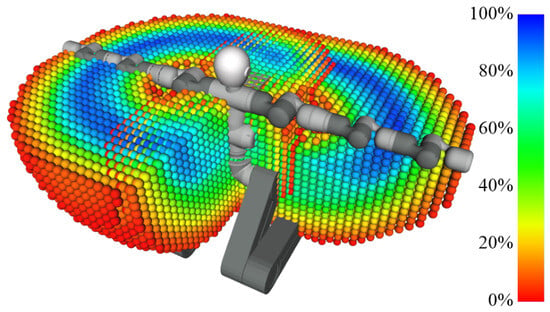
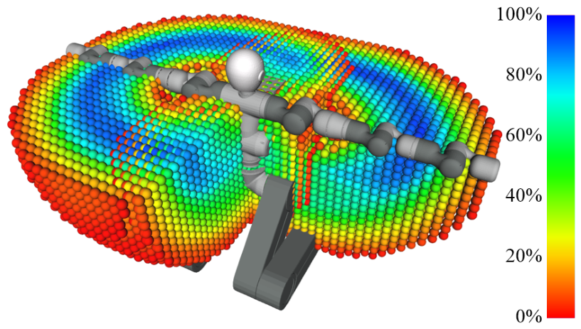
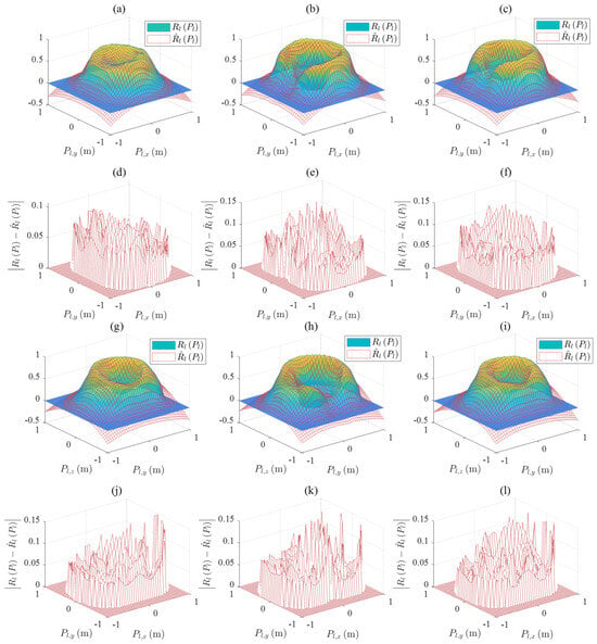
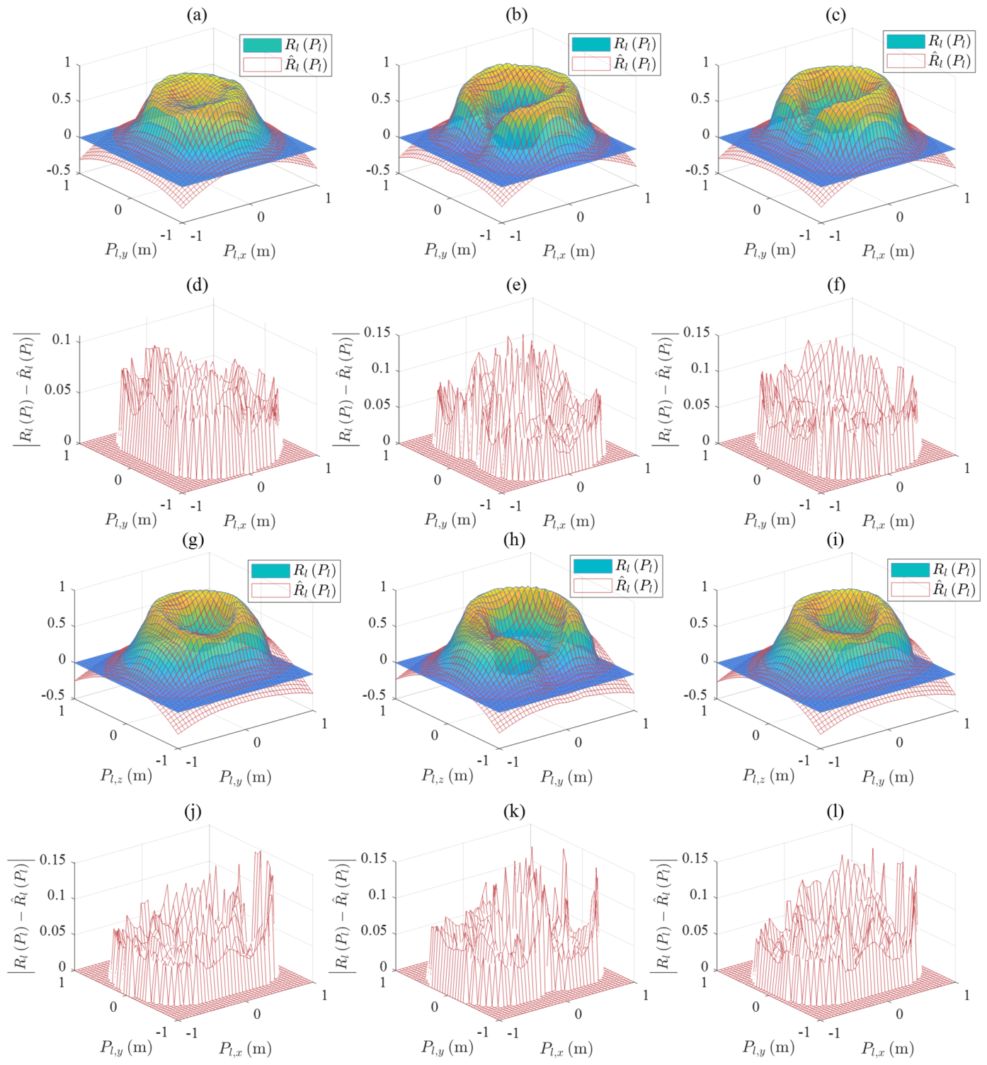
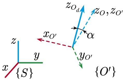
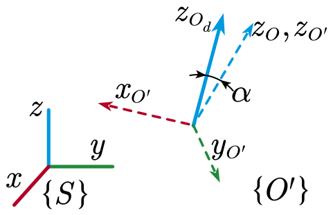
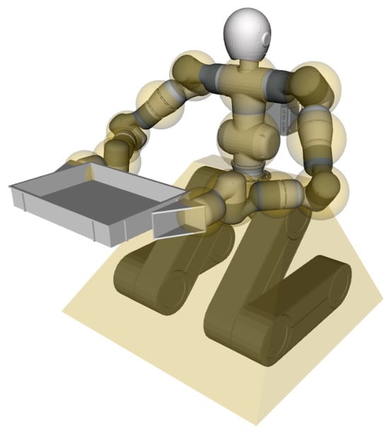
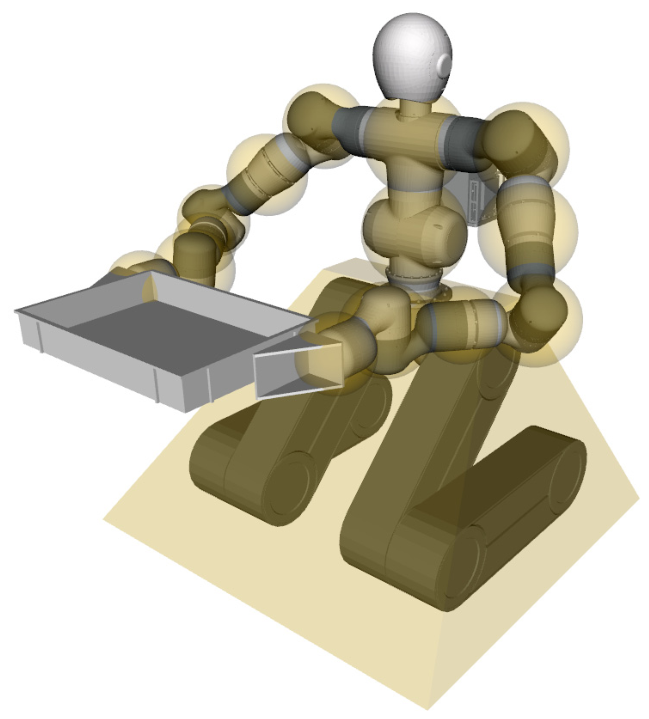
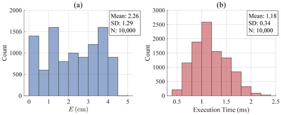
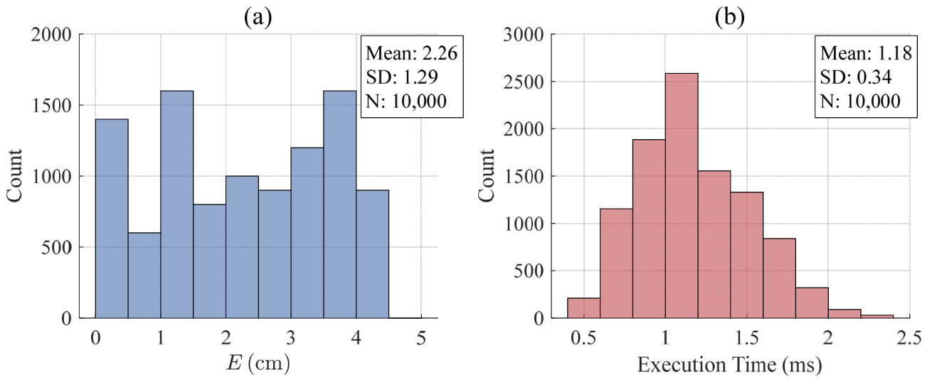
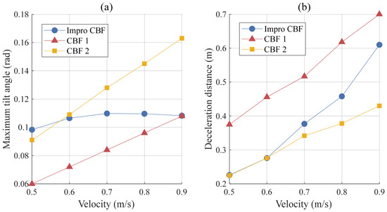
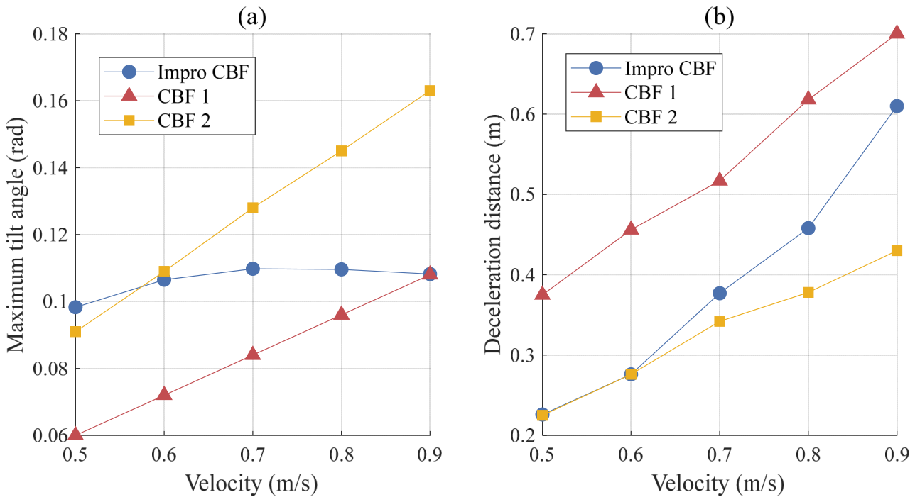
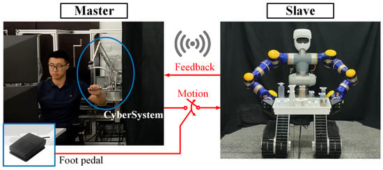
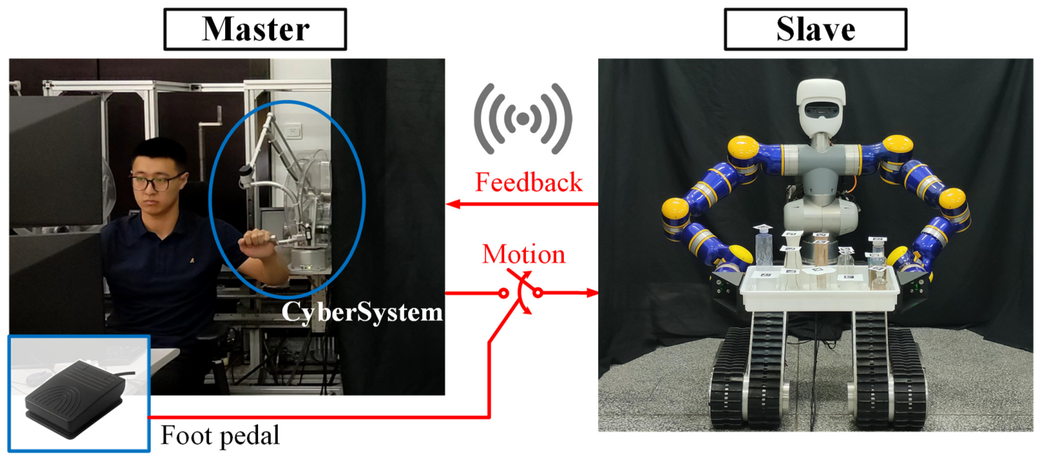
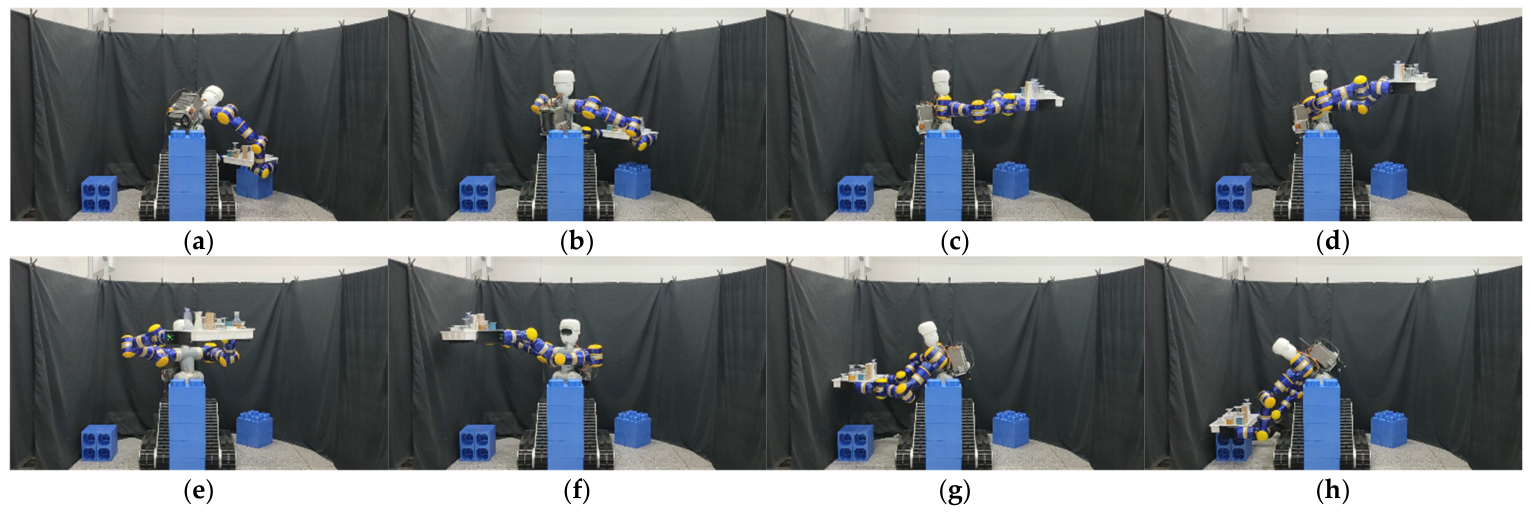


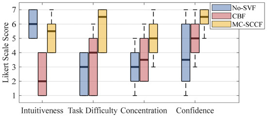
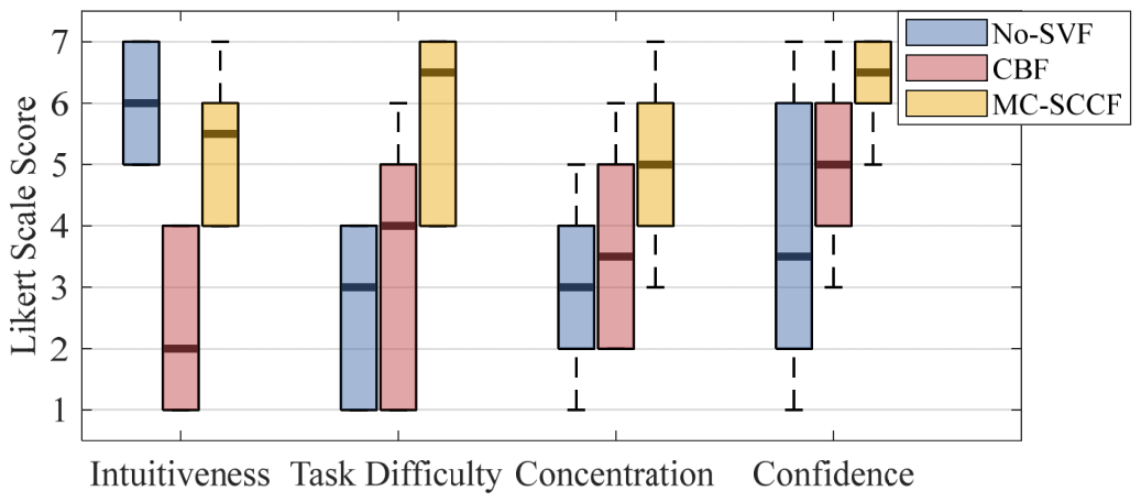
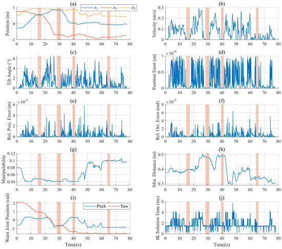
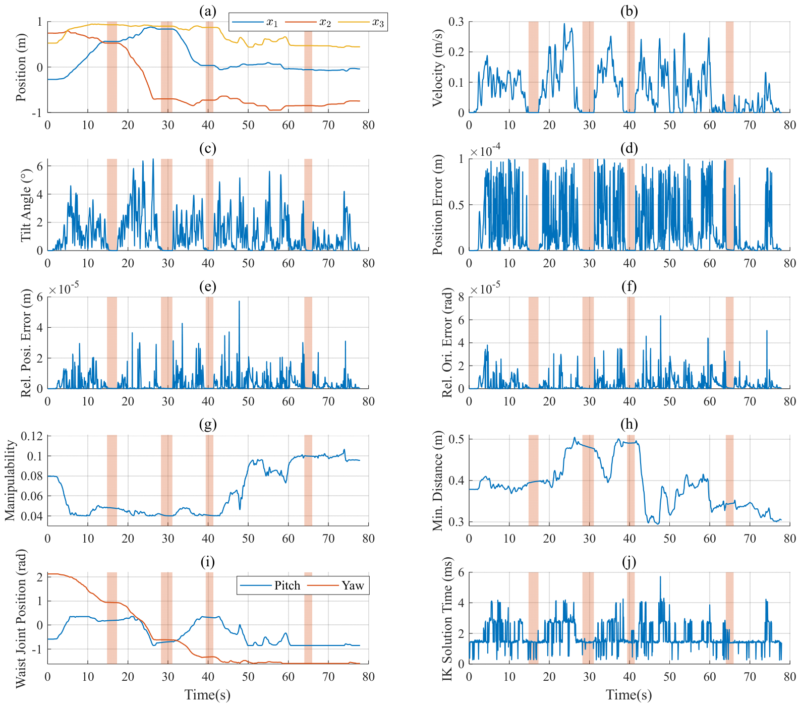

Disclaimer/Publisher’s Note: The statements, opinions and data contained in all publications are solely those of the individual author(s) and contributor(s) and not of MDPI and/or the editor(s). MDPI and/or the editor(s) disclaim responsibility for any injury to people or property resulting from any ideas, methods, instructions or products referred to in the content. |
© 2026 by the authors. Licensee MDPI, Basel, Switzerland. This article is an open access article distributed under the terms and conditions of the Creative Commons Attribution (CC BY) license.