


Abstract
Tool wear monitoring is essential for ensuring machining efficiency and product quality, particularly for difficult-to-machine materials such as Inconel 718 (IN718). Traditional deep learning models, such as Conventional Convolutional Neural Networks (CNNs), often struggle to capture complex wear patterns and lack accuracy across varying machining conditions while developing image-based tool wear identification systems. To address these limitations, this paper presents a Vision Transformer (ViT) model for identifying tool-wear categories during end-milling of IN718. The performance of the ViT-based model is systematically compared with a CNN-based EfficientNet-b0 model. The robustness and generalization of the ViT-based model are validated on two previously unseen image datasets: one with conditions similar to those of the training data and another acquired under varying lighting conditions. The results indicate that the ViT model outperforms the EfficientNet-b0 model in terms of classification accuracy and computational efficiency. The ViT model achieves higher accuracy with fewer training epochs and faster convergence. Furthermore, it exhibits strong generalization across different lighting conditions, demonstrating robustness to variations in the machining environment. The findings presented in this work clearly demonstrate ViT’s effectiveness in tool wear classification and its potential as a reliable, efficient algorithm for developing tool wear monitoring systems for practical machining applications.
1. Introduction
Implementing tool-wear identification systems is crucial during end milling of hard materials such as Inconel 718 (IN718) to maintain productivity and part quality. Tool wear progression during end milling of IN718 is stochastic and varies considerably even under identical machining conditions [1,2]. The variability in wear progression is attributed to elevated temperatures, extreme abrasive behavior at the chip–tool interface, and the simultaneous occurrence of wear mechanisms such as abrasion, adhesion, diffusion, and fracture [3,4,5]. Numerical and computational models reported in the literature remain limited in their ability to reliably identify and predict tool wear states during IN718 machining [6,7,8]. Therefore, a robust and effective tool wear identification system is needed to ensure timely replacement of the cutting tools, avoiding poor surface finish, catastrophic failure, and suboptimal utilization of tool life [9].
The image-based direct evaluation of tool wear states has been widely recognized in the literature as an effective and reliable approach compared to indirect sensor-based methods [10]. It employs a vision system, equipped with cameras, microscopes, or infrared sensors, to capture high-resolution images of the cutting tool [11], enabling quantitative assessment of wear metrics such as flank wear width [12] or crater wear depth [13]. Despite their higher precision, manual inspections performed at periodic intervals are prone to variability across operators, tools, and machines, potentially leading to premature or delayed tool replacements. Therefore, automating direct monitoring approaches with minimal human intervention is essential to achieve consistent, cost-effective, and real-time tool wear assessment [14,15]. With the onset of Industry 4.0 (I4.0), data-driven techniques have demonstrated significant potential to enhance tool wear identification by leveraging large volumes of image data and advanced learning algorithms, enabling accurate, adaptive, and automated decision-making in machining environments [16].
The advent of deep learning algorithms has expanded the capabilities of machine vision systems for automated decision-making by enabling the development of I4.0-compliant monitoring systems. The image-based systems presented in the literature commonly employ Convolutional Neural Network (CNN) models to leverage advanced feature extraction for automatically identifying and classifying complex wear patterns from high-resolution images of cutting tools [17,18,19,20,21,22]. Bergs et al. [17] developed a CNN-based model using a diverse set of cutting tool images acquired with a microscope. The images were preprocessed through enhancement and labeling before developing the trained model for tool type classification and flank wear detection. García-Pérez et al. [18] proposed a framework using the EfficientNet-b4 algorithm for classifying the conditions of round inserts into OK/NOK states during the turning operation. The algorithm achieved 97.8% accuracy on round inserts but failed to replicate a similar performance during deployment on rhombic inserts. Scharf et al. [19] employed a CNN-based U-Net model to classify step-drills as OK or NOK (worn) by analyzing 11 segmented images of the peripheral cutting edges. The study evaluated each segment individually and classified the entire cutting tool as unusable if a single NOK prediction occurred. However, the proposed approach reduced effective tool-life utilization, as a single misclassification among the 11 segments triggered a tool change. Recently, Kumar et al. [20] employed a CNN-based EfficientNet-b0 model to identify tool wear states during the machining of IN718. It has been reported that the presence of multiple wear states within a single image can significantly reduce the predictive performance of a vanilla EfficientNet-b0 model. The study showed that lower classification accuracy on unseen datasets can be effectively addressed through human interventions. Recently, Singh et al. [21] enhanced the diversity of the training dataset by developing image augmentation techniques that effectively mimic a practical machining environment and improve the efficiency of the EfficientNet-b0 model. Turan and Mamedov [23] encoded audible signals into Mel-Frequency Cepstral Coefficient (MFCC) heatmaps and classified end mill wear states as idle, fresh, moderate, and worn using a CNN-based model, achieving a test accuracy of 93–96% across different cutting speeds.
The literature demonstrates the capabilities and limitations of CNN-based models for image-based tool wear identification in extracting and learning complex features from images. Additionally, CNN models are pretrained on large-scale datasets such as ImageNet and fine-tuned on a relatively smaller tool wear dataset to reduce the need for extensive experiments [24]. The effectiveness of CNN-based models is often constrained during milling of IN718 due to challenges in identifying complex and overlapping wear patterns [20]. Machining of IN718 is characterized by the simultaneous occurrence of multiple wear types, such as flank wear, built-up edge (BUE), face wear, and edge chipping. It poses challenges for CNN models, leading to misclassifications when distinguishing multiple wear types within a single image. Furthermore, the limited representation of certain wear patterns in the dataset (e.g., BUE) can reduce model generalization, as representative conditions are not adequately captured. Also, the stochastic wear progression during milling of IN718 further increases the misclassification rate of CNN-based models, underscoring the need for robust approaches capable of handling such complexities.
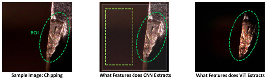
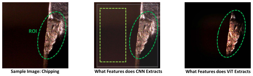
The other challenge in milling of IN718 is image variability arising from image acquisition in harsh machining environments [21]. The presence of chips, coolant residues, and debris can contaminate the tool surface or camera lens system, leading to degraded image quality and potential misclassification. For instance, face wear may be misidentified as BUE due to adhered particles. Additionally, variable lighting conditions further reduce image consistency, limiting the CNN-based model’s ability to reliably detect wear features. Ensuring consistent imaging in such dynamic conditions often requires advanced preprocessing techniques or specialized hardware, such as high-pressure air systems to remove debris, thereby increasing implementation complexity and cost. These limitations highlight the need for a robust model that can accurately identify tool wear types across diverse machining environments without relying on specialized or tightly controlled imaging systems. To address these limitations, Vision Transformers (ViTs) have emerged as a promising alternative to CNN-based approaches for tool wear monitoring systems. Unlike CNNs, which primarily rely on local receptive fields, ViTs process images as sequences of patches and utilize self-attention mechanisms to capture global dependencies [25]. The ability to model long-range interactions enables effective identification of complex and spatially distributed wear patterns. Figure 1 compares fundamental differences in feature extraction between CNN and ViT for a tool wear image. It can be seen that CNNs focus on local feature learning while ViTs capture global contextual relationships.
Figure 1.
Feature extraction in Convolutional Neural Network (CNN) and Vision Transformer (ViT).
Recent studies have implemented transformer-based models for tool wear monitoring or prediction. Liu et al. [26] developed a pure transformer-based architecture that emphasizes the self-attention mechanism and captures long-range dependencies in tool wear progression. The model was extended by developing a hybrid model, CNN–Transformer (CNNT), that combines local feature extraction from CNNs with global context modeling from transformers [27]. The hybrid model demonstrated performance improvement due to the combined features of CNN and transformers. However, both models were developed using indirect monitoring data of cutting forces, vibrations, and acoustic emissions, which are susceptible to noise and outliers and may exhibit weak correlation with actual tool wear states [28]. Sun et al. [29] developed a ViT model to monitor wear on the micro-milling tools using worn images of the bottom cutting edge and categorized the wear state into no-wear, initial wear, normal wear, and severe wear. The ViT model demonstrated higher accuracy than CNN-based models such as EfficientNet, VGG, and ResNet. However, the model’s ability to identify wear states based on underlying mechanisms (i.e., flank, crater, built-up edge, or chipping) and to handle coexisting wear states in a single image has not been evaluated. Furthermore, the model does not account for image acquisition variability in harsh machining environments, such as lighting changes and visual obstructions caused by coolant or chips. In recent studies, Dong et al. [30] encoded time-series force signals into a 2-D image using a Markov Transition Field (MTF) technique. The resulting images were analyzed using a ViT model combined with a Kolmogorov–Arnold Network (KAN) to identify tool wear states. The study demonstrated the capabilities of ViT models for classifying various tool-wear conditions. The approach relies on transformed signals rather than actual wear images, which may limit the ability to capture true physical characteristics of a worn tool. The actual images of worn cutting tools are essential during model development, as they capture flank wear, BUE, face wear, and chipping. It provides spatial and morphological information about wear regions to enable a realistic evaluation under a practical machine environment. Moreover, image-based approaches better reflect variations arising from machining environments, such as lighting changes, surface contamination, and camera occlusions. Therefore, the present work develops a Vision Transformer (ViT) model trained on actual tool wear images to achieve a more representative and robust tool wear classification model.
2. Tool Wear Monitoring Methodology
The overall methodology for developing an image-based tool wear monitoring system includes the following steps:
- -
- Machining experiments to mimic various tool wear states;
- -
- Image-acquisition setup;
- -
- Data annotation and augmentation;
- -
- Model training;
- -
- Model testing.
The end-milling experiments were performed using IN718 workpiece material (sourced from McMaster-Carr, USA) to generate various worn cutting tool states. Images of worn cutting tools were acquired using an on-machine camera system mounted within the machine tool [31]. Developing ViT models requires a large number of labeled datasets, but only a limited number of worn cutting tool images can be obtained from end-milling experiments. As it is not practical to meet the large dataset requirements of ViT models through end-milling experiments, data augmentation techniques are employed in the present work [21]. The dataset is labeled into four tool wear categories and used as input to develop a tool wear classification model using ViT. The subsequent subsections delineate the steps for developing a tool wear monitoring system.
2.1. Experimental Plan and Dataset Generation
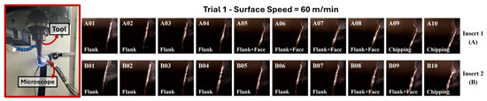
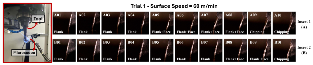
Milling experiments were conducted using a 2-flute end mill with indexable carbide inserts on an IN718 workpiece material. The trochoidal toolpath was used to minimize radial engagement and improve tool life as recommended in the literature [32]. In trochoidal milling, the linear tool motion is superimposed on the rotational motion of the tool center, forming a looping toolpath. The radial offset between successive tool path loops is called the trochoidal step size and is set to 1.5 mm in the present study. The experiments were conducted at three surface speeds, 25, 45, and 60 m/min, maintaining constant feed per tooth, step depth, and toolpath type, as recommended by the cutting tool manufacturer [33]. Table 1 lists cutting conditions and machining parameters used during the end milling experiments. Each machining condition was implemented twice (trials 1 and 2) to account for process variability. The experimental plan included milling 40 mm × 1 mm slots in multiple passes until complete tool failure was recorded. The material removed during each pass was 842.4 mm3, and the tool was moved to a fixed on-machine image-acquisition location using a custom CNC macro to capture worn-tool images. The image acquisition systems consist of a Complementary Metal Oxide Semiconductor (CMOS)-based Dino-Lite microscope, enclosed in a coolant-protective housing and mounted on the wall of the CNC machine, as depicted in Figure 2. The experiments followed ISO-8668-2 standard [34], and a total of 200 images were collected from all inserts and repeated trials. Out of 200 images, 108 were captured during trial 1, while the remaining 92 images were obtained during trial 2.
Table 1.
Plan for machining experiments.
Figure 2.
Image Acquisition Setup and Labeled Image Dataset for Two Inserts at Surface Speed of 60 m/min.
The next step involves labeling of the images, which were categorized into four wear classes: Flank, Flank + Face, Flank + BUE, and Chipping. The categorization is based on the commonly observed wear states during the machining of IN718. The acquired images were annotated by humans with technical expertise in machining and an understanding of the ISO-8668-2 standard [34]. To ensure consistency and reduce ambiguity, multiple annotators reviewed images of worn tools with the acquisition sequence, thereby enabling reliable ground-truth labels. The labeled dataset consists of 89 images in the Flank category, 17 in the Flank + BUE category, 69 in the Flank + Face category, and 25 in the Chipping category. The Flank + BUE wear category has limited original samples as BUE is a transient, short-lived phenomenon that is difficult to capture consistently during experiments. Figure 2 illustrates the annotated progression of tool wear states (A1–A10 and B1–B10) for both milling inserts during the trial-1 machining of IN718 at a surface speed of 60 m/min.
Developing data-driven models such as ViT requires large datasets, extensive experimentation, and significant consumption of raw material. However, milling of IN718 is time-consuming and expensive due to higher material costs. Moreover, the dataset obtained from the machining experiments does not fully capture the range of image variability typically observed during practical machining environments, including coolant or chips on the lens, lighting inconsistencies, tool misalignment, vibration-induced blur, and partial occlusions. To overcome these limitations, experimentally acquired images were augmented to create a diversity-enhanced machining dataset [21]. It was achieved by employing techniques such as flipping, rotation, cropping, scaling, blurring, adding noise, filtering, color jitter, and water-droplet effects. The original dataset of 200 images across different tool wear categories was divided into a 160:40 training–test split, as detailed in Table 2. The training dataset of 160 tool wear images was further expanded into a balanced, significantly larger dataset of 28,000 images, with 7000 images per tool wear category. The detailed augmentation procedure is described in the authors’ previous work along with it effectiveness on unseen test dataset [21].
Table 2.
Original Dataset Split for Training and Testing.
2.2. ViT Architecture for Tool Wear Classification
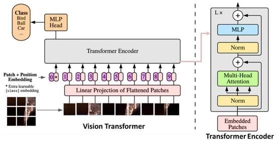
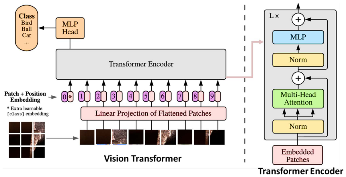
The ViT model is employed as an alternative to a CNN for image-based classification of tool wear states during end milling of IN718. It performs image classification by partitioning a tool-wear image into fixed-size patches. The patches are analyzed as a sequence of tokens processed through a Transformer encoder [25]. Figure 3 shows the overall ViT architecture implemented in this work. The pretrained ViT-Large variant has been used in this study. The input tool wear image of size 224 × 224 pixels is divided into 196 non-overlapping 16 × 16-pixel patches, comprising 24 transformer layers, a hidden dimension of 1024, and 16 attention heads. The patches capture localized wear characteristics, including flank wear, built-up edge (BUE), face wear, and chipping. Each patch is flattened into a vector and projected into a lower-dimensional space using a trainable linear layer, forming patch embeddings. Since Transformers do not inherently encode sequential information, learnable positional embeddings are added to preserve the spatial relationships between wear features across the tool surface. The resulting sequence of embeddings is passed through a Transformer encoder composed of multiple layers of multi-head self-attention and feed-forward networks, with layer normalization applied at each layer. A special classification token is prepended to the sequence, and its final representation is used by a Multilayer Perceptron (MLP) head to classify the tool wear state.
Figure 3.
Architecture of Vision Transformer for Tool Wear State Classification.
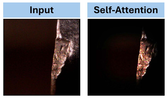
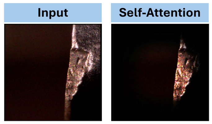
ViTs rely on the self-attention mechanism to capture global contextual relationships across the entire image. The self-attention mechanism enables the model to learn relationships between different regions of the tool wear image by assigning adaptive weights to each patch based on its relevance to others. The mechanism is beneficial for tool wear analysis, as wear patterns may be spatially distributed and interdependent across the tool surface. Furthermore, self-attention enables the model to identify subtle interactions between wear regions that CNNs may not capture effectively. Figure 4 illustrates the output of the self-attention mechanism, showing the model dynamically assigning weights to different regions of the tool wear image and capturing both local features (e.g., small cracks or chipping) and global context (e.g., the overall wear distribution across the tool surface).
Figure 4.
Output of a Self Attention Mechanism.
The self-attention scores are computed by first projecting the input patch embeddings into query , key , and value representations using learnable weight matrices , using Equations (1)–(3). The similarity between patches is then obtained through the scaled dot-product of Q and K, followed by a Softmax operation to normalize the attention weights using Equations (4) and (5). The variable in Equation (4) is the dimension of the key vectors. The weights are subsequently used to compute a weighted sum of the value vectors, resulting in an updated representation emphasizing the most relevant regions of the tool wear image, using Equation (6).
2.3. Training of ViT Model
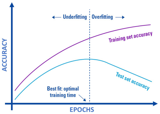
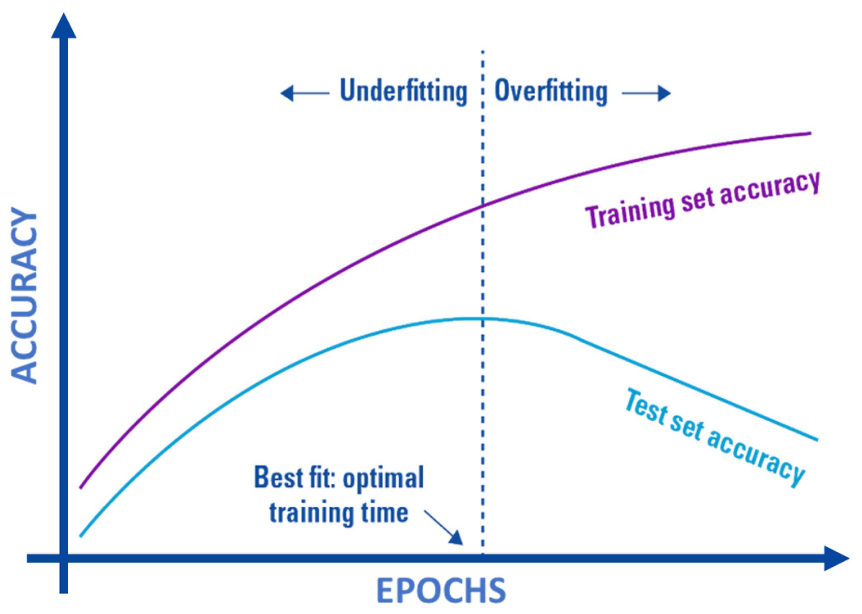
The ViT-based tool wear classification model was trained to achieve higher accuracy and effective generalization on the previously unseen tool wear images. The augmented dataset of 28,000 images discussed in Section 2.1 was used to train the ViT model. The balance between underfitting and overfitting is important during model training. Figure 5 illustrates the relationship between model accuracy and the number of epochs during training. It can be seen that the training accuracy improved with increasing epochs, while the test accuracy increased for a few epochs before declining. Such behavior indicates the onset of overfitting, and the peak test accuracy corresponds to the optimal training duration, or “best fit”, at which the model generalizes best to previously unseen data.
Figure 5.
Relationship between Model Accuracy and Number of Training Epochs.
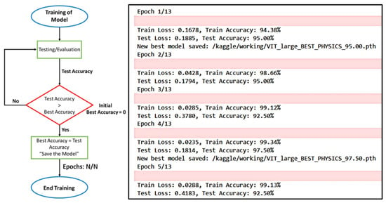
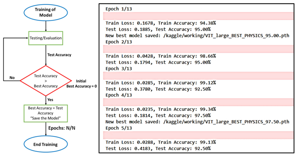
The optimal performance of the ViT model was ensured using a checkpoint strategy shown in Figure 6. The proposed strategy continuously monitors model performance on the test dataset during training and automatically stores the parameters corresponding to the highest test accuracy. The checkpoint strategy allows selecting the best-performing model without relying solely on the final training epoch. The chosen model represents the best trade-off between learning capability and generalization, thereby improving robustness in practical applications. The training was carried out in the NVIDIA T4 x2 GPU-accelerated environment provided by Kaggle to handle the computational demand of the ViT model. The proposed computational system is well-suited for training deep learning models due to the support for parallel computations and efficient handling of large-scale models. The GPU infrastructure provided by Kaggle enables faster training and experimentation, improving overall process efficiency and the scalability of tool wear classification models.
Figure 6.
Checkpoint Strategy for Selecting Optimal Number of Training Epochs.
3. Results and Discussion
This section presents the performance assessment and effectiveness of the developed ViT model for classifying tool-wear states during the end milling of IN718. Section 3.1 compares the performance of a ViT model with a CNN-based EfficientNet-b0 model. The details of the EfficientNet-b0 model architecture, implementation, and configuration parameters adopted in the present work for comparative assessment can be obtained from the authors’ previous work [21]. Further, the generalization abilities of both models under varying machining environments are evaluated on an image dataset acquired under different lighting conditions, and results are summarized in Section 3.2.
3.1. Testing of ViT Model
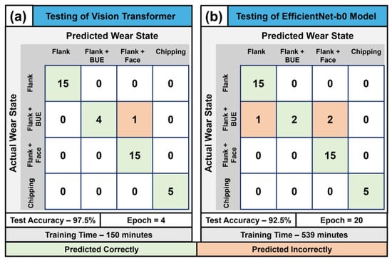
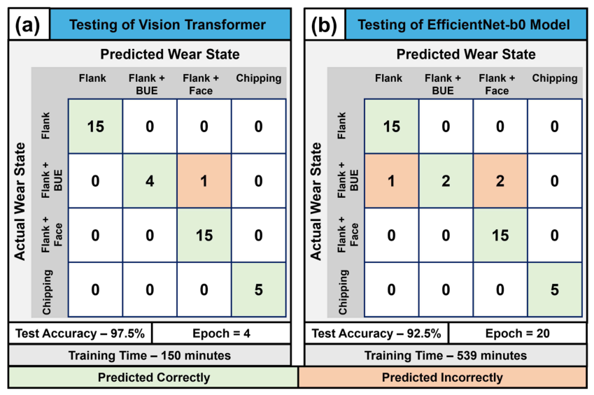
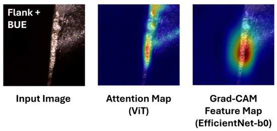
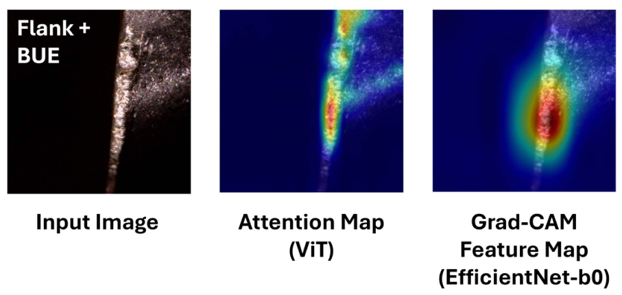
The performance of the trained ViT model was evaluated on the 40-image test dataset that was part of the original dataset of 200 experimentally acquired images and were not used during training. The testing dataset consists of 15 images from the Flank and Flank + Face categories and 5 images each from the Flank + BUE and Chipping categories. The ViT model predictions were compared with those of the EfficientNet-b0 model, and the corresponding confusion matrices are shown in Figure 7. The testing experiments provided clear insights into the comparative performance of both approaches. The ViT model achieved a test accuracy of 97.50%, with only 1 misclassification, outperforming the EfficientNet-b0 model, which attained 92.50% accuracy with 3 misclassifications. The other evaluation metrics, such as precision, recall, and F1-score, were also computed and are presented in Table 3. These metrics are crucial for evaluating performance on imbalanced datasets. A good correlation among these metrics indicates the improved performance of the ViT model for tool wear monitoring. The improvement can be attributed to the global self-attention mechanism, which enables ViT to capture long-range dependencies and model complex spatial relationships across the entire tool wear image. In contrast, the EfficientNet-b0 model primarily focuses on local feature extraction due to a limited receptive field and inherent inductive biases. The difference in feature extraction mechanism can be clearly observed in Figure 8, which shows a tool wear image misclassified by the EfficientNet-b0 model but correctly classified by the ViT model. It also shows the corresponding attention map [35] for the ViT model and the Gradient Class Activation Map (Grad-CAM) visualization [36] for the EfficientNet-b0 model. The comparison of feature maps clearly shows that ViT can effectively distinguish complex or overlapping wear features in an image, while the EfficientNet-b0 model fails due to the dominance of local patterns. The improved performance demonstrates the ViT model’s ability to capture subtle, spatially distributed wear characteristics, which are critical for developing an accurate tool-wear-state classification system during end milling of IN718.
Figure 7.
Confusion Matrices with Test Accuracy and Training Epochs for (a) ViT; and (b) EfficientNet-b0.
Table 3.
Precision, Recall and F1 Score for the 40 Images from the Original Testing Dataset.
Figure 8.
Comparison of ViT Attention Map and EfficientNet-b0 Grad-CAM Visualization for an Image Correctly Classified by ViT but Misclassified by EfficientNet-b0 Model.
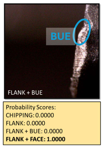
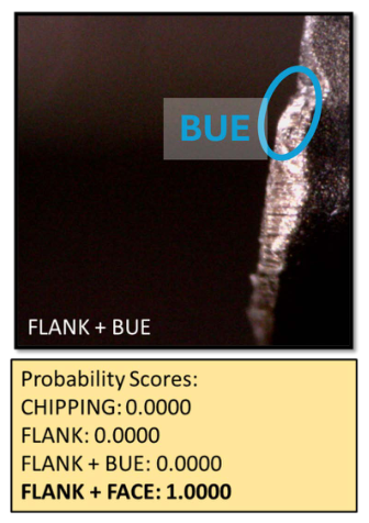
One misclassification of the ViT model was further analyzed by examining the prediction confidence scores, and the results are shown in Figure 9. The image was also misclassified by the EfficientNet-b0 model. It is evident that the misclassified image contains features corresponding to Flank + Face (predicted) and Flank + BUE wear (ground truth) categories. The image was labeled as Flank + BUE by humans due to a small BUE feature (shown in Figure 9), which results in rapid tool progression during end-milling of IN718. Neither algorithm could capture a critical feature of a smaller size, leading to misclassification as a dominant larger feature (Flank + Face in this case) was identified. The misclassification highlighted the importance of a feature’s criticality in determining algorithm performance, as the inability to detect such characteristics can bias predictions towards prominent features. It is noteworthy that the ViT achieved superior accuracy with only 4 training epochs, compared to 20 for the EfficientNet-b0 model. Additionally, the total training time for the ViT model was approximately 150 min, whereas the EfficientNet-b0 model required approximately 539 min under the same computational setup. The lower number of training epochs and reduced training time indicate faster convergence of the ViT model. The faster convergence can be attributed to the self-attention mechanism of ViT, which captures long-range dependencies directly and facilitates more efficient feature representation than the convolutional operations of the CNN model. The ability of a ViT model to simultaneously achieve higher accuracy and faster convergence demonstrates its effectiveness in learning complex wear patterns, making it a promising algorithm for developing vision-based tool wear monitoring systems for IN718 machining.
Figure 9.
Representation of Misclassification Results by the ViT Model.
3.2. Testing on Different Lighting Conditions
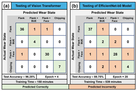
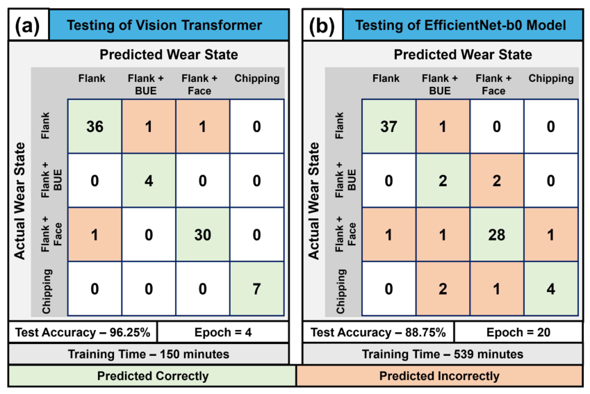
An additional dataset of 80 images were acquired separately under varying lighting conditions using independent inserts while keeping the machining conditions and cutting tool states unchanged. This dataset was used to evaluate the generalization abilities of a ViT model. The testing dataset comprises 38 images of Flank, 31 of Flank + Face, 4 of Flank + BUE, and 7 of Chipping wear states. The dataset introduces variability arising from illumination changes, enabling a focused assessment of the ViT model’s robustness. These images were not included in the training dataset, thereby preserving the integrity of the evaluation process. The objective is to examine the generalization abilities of trained models when exposed to common visual variations in the presence of similar features exhibiting wear states. The performance of both models was evaluated on the additional dataset comprising 80 images, and the corresponding results are presented using confusion matrices in Figure 10.
Figure 10.
Confusion Matrices with Test Accuracy and Training Epochs under Varying Lighting Conditions for (a) ViT; and (b) EfficientNet-b0.
The comparative evaluation across varied lighting conditions also shows that ViT outperformed EfficientNet-b0 in predicting all wear classes. The ViT model achieved a test accuracy of 96.25% with three misclassifications, whereas EfficientNet-b0 reached 88.75% with nine misclassifications, despite EfficientNet-b0 requiring five times more training epochs and approximately 3.6 times higher training time. The other metrics presented in Table 4 also show good correlation for images acquired under different lighting conditions. The results clearly demonstrate the robustness of a ViT model in identifying subtle, localized wear types, such as Flank + BUE, even under altered lighting conditions. The results highlight the ViT model’s superior generalization ability in extracting critical features across diverse datasets. Such features make the ViT model an effective solution for monitoring tool wear states in demanding machining applications, such as IN718.
Table 4.
Precision, Recall and F1 Score for the 80 Images Acquired under Different Lighting Conditions.
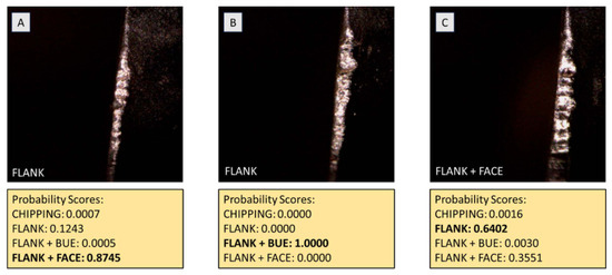
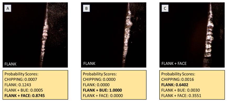
Three misclassifications of the ViT model were further analyzed to understand the underlying causes of error, and the results are shown in Figure 11A–C. It can be seen that the misclassification of image A is due to intense reflections and a textured pattern along the cutting edge, resembling the features of Face wear. Such visual artifacts may confuse the self-attention mechanism, as similar patterns were frequently associated with features representing Flank + Face wear in the training dataset. Also, the Flank wear is not clearly distinguishable in this case, further contributing to the misclassification. In image B, the model appears to have incorrectly identified features resembling BUE, leading to the misclassification. The brighter regions or small deposits along the worn surface may have been interpreted as metallic accumulations associated with features representing the BUE. The misinterpretation of lighting glare as BUE may be due to the limited number of original BUE images in the training dataset, leading to insufficient representation of this wear category. Additionally, augmentation involving illumination variations may introduce BUE-like patterns, affecting the model’s ability to distinguish between actual BUE and similar visual artifacts. In Image C, the ViT underestimates the presence of face wear. Variations in lighting may obscure the transition between the flank and face regions, reducing the model’s attention to the feature representing Face wear. The relatively lower confidence in the Flank wear category and moderate probability assigned to Flank + Face further indicate uncertainty in the prediction. Overall, these misclassifications highlight the model’s sensitivity to lighting conditions and subtle feature variations, suggesting the need to effectively capture such cases in the training dataset.
Figure 11.
Analysis of Misclassifications in ViT Model under Different Lighting Conditions, Labeled as: (A) Flank; (B) Flank; and (C) Flank + Face.
4. Conclusions
This paper presented the development of a ViT model for identifying tool wear states using vision-based systems during end milling of IN718. The training datasets for the model development were captured by systematically performing end milling experiments and acquiring images in the machine environment. The performance of the developed ViT model was compared with a CNN-based EfficientNet-b0 model. Both models were evaluated using previously unseen image datasets obtained under two different conditions—one with conditions similar to those employed while obtaining the training data and another dataset captured under varying lighting conditions in the machining setup—to assess their robustness and generalization capabilities. The ViT model outperformed the EfficientNet-b0 model, achieving higher accuracy and faster convergence. The improved performance can be attributed to the self-attention mechanism, which enables effective modeling of global image dependencies and facilitates the identification of subtle and complex wear patterns. Furthermore, the ViT model demonstrated strong generalization across different lighting conditions, highlighting its robustness to variations in the machining environment. The findings suggest that ViT can be a reliable and efficient algorithm for developing tool-wear monitoring systems for the machining of difficult-to-cut materials such as IN718.
However, the observed performance is based on a relatively small dataset, which can be further substantiated using larger, more diverse datasets to ensure robust generalization and industrial reliability. In addition, further studies will investigate the influence of ViT hyperparameters, such as patch size and transformer depth, on tool wear classification performance. Although the present work evaluates robustness under varying lighting conditions, future research will also consider other real-time machining disturbances, including coolant contamination, chip adhesion, vibration-induced blur, and camera misalignment.
Author Contributions
Conceptualization, G.S. and A.A.; methodology, G.S.; software, G.S.; validation, G.S., A.A. and K.A.D.; formal analysis, G.S. and A.A.; investigation, G.S.; resources, K.A.D.; data curation, A.A.; writing—original draft preparation, A.A.; writing–review and editing, A.A. and K.A.D.; visualization, A.A. and K.A.D.; supervision, K.A.D. and A.A.; project administration, L.M.; funding acquisition, L.M. All authors have read and agreed to the published version of the manuscript.
Funding
This research was funded by the National Science Foundation, United States, under grant number 1760809. Any opinions, findings, conclusions, or recommendations expressed in this material are those of the authors and do not necessarily reflect the views of the National Science Foundation.
Institutional Review Board Statement
Not applicable.
Informed Consent Statement
Not applicable.
Data Availability Statement
The data that support the findings of this study are available from the corresponding author upon reasonable request.
Acknowledgments
The authors thank the Ministry of Education (MoE), India, for providing financial support as a student fellowship to Garvit Singh for carrying out this research work. The authors would also like to thank Karan Bhuta for his help in data collection.
Conflicts of Interest
The authors declare no conflicts of interest. The funders had no role in the design of the study; in the collection, analyses, or interpretation of data; in the writing of the manuscript; or in the decision to publish the results.
References
- Potthoff, N.; Agarwal, A.; Wöste, F.; Wiederkehr, P.; Mears, L. Evaluation of Contrived Wear Methodology in End Milling of Inconel 718. J. Manuf. Sci. Eng. 2023, 145, 101002. [Google Scholar] [CrossRef] [Scilit]
- Suárez, A.; Veiga, F.; Sandua, X.; Rivero, P.J.; de Lacalle, L.N.L.; Wretland, A. Machinability of Waspaloy: An investigation of cutting forces and tool wear in turning. Int. J. Adv. Manuf. Technol. 2025, 139, 3159–3172. [Google Scholar] [CrossRef] [Scilit]
- Thakur, D.; Ramamoorthy, B.; Vijayaraghavan, L. An experimental analysis of effective high speed turning of superalloy Inconel 718. J. Mater. Sci. 2009, 44, 3296–3304. [Google Scholar] [CrossRef] [Scilit]
- Xavior, M.A.; Manohar, M.; Jeyapandiarajan, P.; Madhukar, P.M. Tool wear assessment during machining of Inconel 718. Procedia Eng. 2017, 174, 1000–1008. [Google Scholar] [CrossRef] [Scilit]
- Pérez-Salinas, C.; de Lacalle, L.N.L.; del Olmo, A.; Kumar, C.S. The relationship between the cutting-edge, tool wear, and chip formation during Inconel 718 dry cutting. Int. J. Adv. Manuf. Technol. 2024, 132, 6001–6017. [Google Scholar] [CrossRef] [Scilit]
- Liang, X.; Liu, Z.; Wang, B. State-of-the-art of surface integrity induced by tool wear effects in machining process of titanium and nickel alloys: A review. Measurement 2019, 132, 150–181. [Google Scholar] [CrossRef] [Scilit]
- Pimenov, D.Y.; Bustillo, A.; Wojciechowski, S.; Sharma, V.S.; Gupta, M.K.; Kuntoğlu, M. Artificial intelligence systems for tool condition monitoring in machining: Analysis and critical review. J. Intell. Manuf. 2023, 34, 2079–2121. [Google Scholar] [CrossRef] [Scilit]
- Zhang, H.; Jiang, S.; Gao, D.; Sun, Y.; Bai, W. A review of physics-based, data-driven, and hybrid models for tool wear monitoring. Machines 2024, 12, 833. [Google Scholar] [CrossRef] [Scilit]
- Sheng, X.; Zhu, Z.; Liu, C. A Review of the Machining Mechanisms in Field-Assisted Cutting of Brittle Materials. Micromachines 2026, 17, 361. [Google Scholar] [CrossRef] [Scilit]
- Yu, J.; Cheng, X.; Lu, L.; Wu, B. A machine vision method for measurement of machining tool wear. Measurement 2021, 182, 109683. [Google Scholar] [CrossRef] [Scilit]
- Dai, Y.; Zhu, K. A machine vision system for micro-milling tool condition monitoring. Precis. Eng. 2018, 52, 183–191. [Google Scholar] [CrossRef] [Scilit]
- Peng, R.; Liu, J.; Fu, X.; Liu, C.; Zhao, L. Application of machine vision method in tool wear monitoring. Int. J. Adv. Manuf. Technol. 2021, 116, 1357–1372. [Google Scholar] [CrossRef] [Scilit]
- Prasad, K.N.; Ramamoorthy, B. Tool wear evaluation by stereo vision and prediction by artificial neural network. J. Mater. Process. Technol. 2001, 112, 43–52. [Google Scholar] [CrossRef] [Scilit]
- Mohamed, A.; Hassan, M.; M’Saoubi, R.; Attia, H. Tool condition monitoring for high-performance machining systems—A review. Sensors 2022, 22, 2206. [Google Scholar] [CrossRef] [Scilit]
- Munaro, R.; Attanasio, A.; Del Prete, A. Tool wear monitoring with artificial intelligence methods: A review. J. Manuf. Mater. Process. 2023, 7, 129. [Google Scholar] [CrossRef] [Scilit]
- Nasir, V.; Sassani, F. A review on deep learning in machining and tool monitoring: Methods, opportunities, and challenges. Int. J. Adv. Manuf. Technol. 2021, 115, 2683–2709. [Google Scholar] [CrossRef] [Scilit]
- Bergs, T.; Holst, C.; Gupta, P.; Augspurger, T. Digital image processing with deep learning for automated cutting tool wear detection. Procedia Manuf. 2020, 48, 947–958. [Google Scholar] [CrossRef] [Scilit]
- García-Pérez, A.; Ziegenbein, A.; Schmidt, E.; Shamsafar, F.; Fernández-Valdivielso, A.; Llorente-Rodríguez, R.; Weigold, M. CNN-based in situ tool wear detection: A study on model training and data augmentation in turning inserts. J. Manuf. Sys. 2023, 68, 85–98. [Google Scholar] [CrossRef] [Scilit]
- Scharf, H.P.; Cambraia, H.N.; da Costa, D.D. A new embedded vision system for monitoring tool conditions in production lines using a combination of direct and indirect methods. J. Manuf. Process. 2023, 102, 143–153. [Google Scholar] [CrossRef] [Scilit]
- Kumar, A.S.; Agarwal, A.; Jansari, V.G.; Desai, K.; Chattopadhyay, C.; Mears, L. HG-XAI: Human-guided tool wear identification approach through augmentation of explainable artificial intelligence with machine vision. J. Intell. Manuf. 2025, 36, 4807–4822. [Google Scholar] [CrossRef] [Scilit]
- Singh, G.; Agarwal, A.; Desai, K.A.; Mears, L. Systematic approach for generating diversity-enhanced image dataset for vision-based on-machine tool wear monitoring systems. Int. J. Adv. Manuf. Technol. 2026, 1–12. [Google Scholar] [CrossRef] [Scilit]
- Wu, X.; Liu, Y.; Zhou, X.; Mou, A. Automatic identification of tool wear based on convolutional neural network in face milling process. Sensors 2019, 19, 3817. [Google Scholar] [CrossRef] [Scilit]
- Turan, H.I.; Mamedov, A. Tool Wear Detection in Milling Using Convolutional Neural Networks and Audible Sound Signals. Machines 2026, 14, 59. [Google Scholar] [CrossRef] [Scilit]
- Pan, S.J.; Yang, Q. A survey on transfer learning. IEEE Trans. Knowl. Data Eng. 2009, 22, 1345–1359. [Google Scholar] [CrossRef] [Scilit]
- Dosovitskiy, A.; Beyer, L.; Kolesnikov, A.; Weissenborn, D.; Zhai, X.; Unterthiner, T.; Dehghani, M.; Minderer, M.; Heigold, G.; Gelly, S.; et al. An image is worth 16x16 words: Transformers for image recognition at scale. arXiv 2020, arXiv:2010.11929. [Google Scholar]
- Liu, H.; Liu, Z.; Jia, W.; Lin, X.; Zhang, S. A novel transformer-based neural network model for tool wear estimation. Meas. Sci. Technol. 2020, 31, 065106. [Google Scholar] [CrossRef] [Scilit]
- Liu, H.; Liu, Z.; Jia, W.; Zhang, D.; Wang, Q.; Tan, J. Tool wear estimation using a CNN-transformer model with semi-supervised learning. Meas. Sci. Technol. 2021, 32, 125010. [Google Scholar] [CrossRef] [Scilit]
- Zhang, C.; Zhang, J. On-line tool wear measurement for ball-end milling cutter based on machine vision. Comput. Ind. 2013, 64, 708–719. [Google Scholar] [CrossRef] [Scilit]
- Sun, Q.; Yu, Z.; Li, Y.; Yang, S.; Xu, J.; Yu, H. Wear status prediction of micro milling tools by transfer learning and ViT model. In Proceedings of the 2021 IEEE International Conference on Manipulation, Manufacturing and Measurement on the Nanoscale (3M-NANO); IEEE: Piscataway, NJ, USA, 2021; pp. 183–187. [Google Scholar] [CrossRef] [Scilit]
- Dong, S.; Meng, Y.; Yin, S.; Liu, X. Tool wear state recognition study based on an MTF and a vision transformer with a Kolmogorov-Arnold network. Mech. Syst. Signal Process 2025, 228, 112473. [Google Scholar] [CrossRef] [Scilit]
- Kumar, A.S.; Agarwal, A.; Jansari, V.G.; Desai, K.; Chattopadhyay, C.; Mears, L. Realizing on-machine tool wear monitoring through integration of vision-based system with CNC milling machine. J. Manuf. Sys. 2025, 78, 283–293. [Google Scholar] [CrossRef] [Scilit]
- Pleta, A.; Ulutan, D.; Mears, L. Investigation of Trochoidal Milling in Nickel-Based Superalloy Inconel 718 and Comparison With End Milling. Int. Manuf. Sci. Eng. Conf. 2014, 45813, V002T02A058. [Google Scholar] [CrossRef] [Scilit]
- Coromant, S. Cutting Data Calculation; Sandvik Coromant: Sandviken, Sweden, 2023. Available online: https://www.sandvik.coromant.com/en-gb/tools/digital-machining/coroplus-tool-guide (accessed on 25 May 2025).
- ISO8688-2; Tool Life Testing in Milling. Part 2: End Milling. International Organization for Standardization (ISO): Geneva, Switzerland, 1989. Available online: https://www.iso.org/obp/ui/#iso:std:iso:8688:-2:ed-1:v1:en (accessed on 18 May 2026).
- Liao, Y.; Gao, Y.; Zhang, W. Dynamic accumulated attention map for interpreting evolution of decision-making in vision transformer. Pattern Recognit. 2025, 165, 111607. [Google Scholar] [CrossRef] [Scilit]
- Selvaraju, R.R.; Cogswell, M.; Das, A.; Vedantam, R.; Parikh, D.; Batra, D. Grad-CAM: Visual Explanations from Deep Networks via Gradient-Based Localization. Int. J. Comput. Vision. 2020, 128, 336–359. [Google Scholar] [CrossRef] [Scilit]

Disclaimer/Publisher’s Note: The statements, opinions and data contained in all publications are solely those of the individual author(s) and contributor(s) and not of MDPI and/or the editor(s). MDPI and/or the editor(s) disclaim responsibility for any injury to people or property resulting from any ideas, methods, instructions or products referred to in the content. |
© 2026 by the authors. Licensee MDPI, Basel, Switzerland. This article is an open access article distributed under the terms and conditions of the Creative Commons Attribution (CC BY) license.