


Abstract
Closed-circuit axial piston pumps in the travel hydraulic systems of heavy-duty engineering vehicles are highly vulnerable to severe transient cavitation during emergency braking. Rapid pressure reversal at the interface between the cylinder bore and the valve plate causes volumetric efficiency loss, intensified pressure pulsation, and erosion damage; however, the coupled mechanism by which throttling, vortex formation, and cavitation interact in this region, together with its structural regulation pathway, remains insufficiently understood. To address this gap, a closed-circuit axial piston pump for cotton pickers was investigated under emergency braking as a representative extreme loading scenario. A full-passage transient CFD model was established and validated against steady-state volumetric efficiency tests on a heavy-load test bench, as well as against PIV internal flow visualization on a Reynolds-scaled transparent model. Parametric transient CFD sweeps were then performed, and a multi-objective optimization model was developed and solved using a Kriging-assisted NSGA-II algorithm with entropy-weighted TOPSIS decision-making. The results identify the interface between the cylinder bore and the valve plate as the primary cavitation zone, with cavitation driven by local throttling and wall-attached vortices rather than by global low pressure. The optimized cylinder bore configuration reduces the peak gas volume fraction by 34.7% in the total flow domain and by 15.7% in the valve plate region, while maintaining volumetric efficiency above 97.8%; the port plate pressure pulsation increases by 12.97%. The key takeaway is that targeted optimization of the cylinder bore alone, without altering the overall valve plate or piston block architecture, can effectively suppress transient cavitation, while revealing an inherent trade-off with pressure pulsation control. In conclusion, this work clarifies the cavitation mechanism, provides a validated numerical and experimental framework, and offers an implementable design pathway for transient cavitation control of closed-circuit piston pumps under extreme loading conditions.
1. Introduction
Axial piston pumps of closed-circuit configuration serve as the core power components in the travel hydraulic systems of large-scale construction machinery, and their adaptability to extreme operating conditions directly affects the operational efficiency and running safety of equipment. Under extreme transient conditions such as emergency braking of construction machinery, a sudden increase in load causes rapid switching of inlet and outlet pressures, resulting in severe transient flow field distortion at the interface between the cylinder bore and the valve plate. This tends to induce sustained oscillating cavitation, leading to reduced volumetric efficiency, intensified pressure pulsation, and cavitation erosion of components, which has become a key factor restricting the performance and reliability of such pumps. Clarifying the coupled mechanism of transient throttling cavitation at the cylinder bore–valve plate interface under such conditions, and revealing the internal relationship between structural parameters of the cylinder bore and cavitation evolution, is a prerequisite for achieving precise regulation of cavitation in these pumps.
Component-level structural optimization has long been recognized as a primary route to suppress cavitation, and the body of literature in this direction reveals a clear evolution from local groove tuning toward integrated valve plate and piston co-design. Early studies established that the geometry of relief features on the valve plate is the dominant lever: Shi et al. demonstrated that tuning the aspect ratio of the U-shaped damping groove can curb cavitation development, but their conclusions are restricted to the groove itself and do not address how the groove couples with the upstream cylinder bore [1]. Building on this, the work shifted toward the moving member, with Chao et al. proposing a capped piston design to reduce compressibility effects and pressure ripple [2], indicating that piston-side and plate-side flow features are not independent. A subsequent generation of studies pursued multi-feature co-design: Suo et al. coupled piston chamber radius, swash plate angle, and valve plate geometry to mitigate both gaseous and vaporous cavitation [3], and Yan et al. further showed that enlarging the distribution circle radius or piston chamber radius while reducing rotational speed can simultaneously improve flow rate and reduce erosion [4]. Although these contributions progressively broaden the design space, they share two limitations of central importance to the present work: their objective functions are anchored on time-averaged pressure pulsation or volumetric efficiency under steady-state rated conditions, and the cylinder bore itself, the geometric throat that connects the piston chamber to the valve plate kidney, is treated as a passive boundary rather than an active design variable. Consequently, none of the above frameworks have been mapped onto the strongly transient, fully reversed pressure environment of emergency braking, and the structural regulation effect of the cylinder bore on transient cavitation has not been systematically resolved.
In parallel, numerical simulation and visualization diagnostics have matured into the principal tools for probing in-pump cavitation, but a critical capability gap remains for transient pressure reversal scenarios. On the modeling side, Ye et al. coupled CFD with a visualized rig to characterize cavitation in the piston chamber and grooves under varied conditions [5], and Wu et al. confirmed via three-dimensional transient CFD that a novel damping groove can suppress both pressure ripple and cavitation [6]. Both studies demonstrate that high-fidelity transient simulation is feasible, yet their excitations remain quasi-steady. Refinements to the cavitation source-or-sink description followed: Huang et al. exploited centrifugal effects via a conical cylinder block to relieve erosion [7], Pan et al. embedded the coupling between cavitation bubbles and swash plate vibration into an outlet pressure pulsation model [8], and Zhang et al. verified the cavitation mitigation effect of a crescent-shaped unloading hole [9]. These contributions individually advance the physical fidelity of cavitation modeling but do not jointly resolve the global low-pressure background superimposed on local high-speed throttling that defines emergency braking. Methodological precedents for coupling transient CFD with direct flow-field or acoustic-assisted diagnostics have also emerged in adjacent pump-type machinery: Ge et al. combined transient CFD and high-speed visualization to reveal the correlation between cavitation and shear flow in bellows pumps [10], and Al-Obaidi combined CFD and acoustic analysis to clarify the influence of tip-leakage vortices on pressure fluctuation and turbulence in axial pumps under varying flow conditions [11]. On the diagnostic side, the dominant practice exemplified by Pasunurthi et al. [12] and Zhao et al. [13] is to validate models against macroscopic performance signatures, with limited recourse to in situ flow field visualization in the actual cavitation-bearing region. The accumulated insight is therefore lopsided: the macroscopic predictive accuracy of CFD is well established, but its mechanism-resolving power at the cylinder bore and valve plate interface under fully reversed transient pressure has not been independently corroborated by local flow visualization, leaving the throttling, vortex and cavitation chain inferred rather than observed.
Beyond axial piston pumps, the broader application landscape further reveals that emergency braking of closed-circuit travel systems poses a uniquely demanding boundary condition. Voskresensky discussed cavitation in mobile machine hydraulic drives [14], Li et al. linked structural parameters to cavitation severity in hydraulic loaders [15], Manhartsgruber et al. described impact-driven cavitation in steel-rolling hydraulics [16], Yang et al. characterized water hydraulic axial piston motors [17], and Yang et al. combined CFD with multi-objective optimization for hydrodynamic retarders [18]. These works enlarge the application context but address neither the complete inlet and outlet pressure inversion nor the millisecond scale boundary excursions characteristic of cotton picker emergency braking, indicating that a dedicated mechanism analysis and structural strategy is still required for this class of closed-circuit pumps.
At the algorithmic level, the coupling of evolutionary algorithms with CFD trained surrogate models has become the de facto framework for pump performance enhancement, and the trajectory of recent work helps position the contribution of the present study. Within the pump cavitation domain, Huang et al. improved NSGA-II with dynamic crowding distance handling for mixed-flow impellers [19], Ren et al. coupled CFD-DEM with NSGA-III for double-vane pumps [20], Gül et al. integrated RBF surrogates with NSGA-II for centrifugal impellers [21], Zhang et al. embedded neural networks into NSGA-II for a helicon axial multiphase pump impeller [22], and Sun et al. addressed bidirectional axial-flow pumps under combined lift-drag and cavitation criteria [23]. Closely related to cavitation modeling, Apte et al. employed multi-objective optimization specifically to evaluate turbulence closures for unsteady cavitating flows, providing important guidance on closure selection but not on geometry design [24]. Across nearly all of the above works, the optimization objectives are built upon time-averaged performance indicators obtained under steady-state conditions. As a result, the strong transient excursions that characterize emergency braking are not represented in the objective formulation. Even when the time-averaged performance satisfies the design targets, individual transient peaks may exceed the cavitation failure threshold and trigger local damage. Existing formulations therefore lack the boundary coverage required for closed-circuit piston pumps under emergency braking, and an optimization framework driven by transient extreme values is needed.
In summary, existing studies have laid an important foundation in the field of pump cavitation mechanism and suppression methods. However, there are still three main deficiencies in the cavitation control of the interface between the cylinder bore and the valve plate under the extreme transient operating conditions of engineering applications. Firstly, the coupling mechanism of throttling-vortex-cavitation in this region under strong transient pressure reversal has not been fully revealed, and the internal correlation between structural parameters and cavitation evolution has not yet formed a systematic understanding. Secondly, the targeted optimization research on the cylinder bore, which is the core flow interface, is relatively limited. Existing optimizations mostly focus on traditional components such as the valve plate and piston, making it difficult to adapt to the operating requirements of transient pressure switching. Finally, most of the existing multi-objective optimization models adopt steady-state time-averaged performance indicators as objective functions, which are difficult to effectively cover the transient extreme boundary in the emergency braking extreme conditions.
This study focuses on the aforementioned issues, taking the 180 mL/r axial closed-type piston pump supporting cotton pickers as the research carrier, and conducts multi-objective targeted optimization research on the cylinder bore structure under its emergency braking extreme conditions. Firstly, a full-flow transient CFD numerical model is established; the cavitation core region is located based on the gas volume fraction contour and sub-region time-varying curves, and the cavitation induction chain is initially proposed. The macro-performance prediction accuracy of the model is verified by means of a steady-state heavy-load test bench, and the double vortex structure in the interface between the cylinder bore and the valve plate is directly observed through PIV internal flow field visualization tests based on the Reynolds similarity criterion, reflecting the above mechanism from the experimental perspective. On this basis, three types of core parameters radial radius, radial angle, and axial inclination angle of the cylinder bore are selected to carry out full-parameter transient CFD simulations, quantifying their regulation laws on the three links of cavitation initiation, full-cycle dynamic evolution, and continuous development. A multi-objective optimization model centered on full-cycle extreme eigenvalues is constructed, and the composite optimized structure of the cylinder bore is obtained by solving with the Kriging surrogate model assisted by the NSGA-II algorithm. The effectiveness and robustness of the scheme are verified through multi-condition simulations. The purpose of this study is to deepen the understanding of the transient cavitation coupling mechanism of closed-type axial piston pumps under emergency braking conditions, explore the targeted optimization path of the cylinder bore structure, and provide a reference for improving the extreme condition performance of core components in the traveling system of large construction machinery such as cotton pickers. It should be noted that, due to the limitations of test conditions, the emergency braking transient extreme conditions cannot be fully reproduced on the test bench, and this study has not yet completed the full-machine test of the optimized pump on the actual cotton picker; relevant contents will be further improved in subsequent studies.
2. Materials and Methods
2.1. Structural Parameters
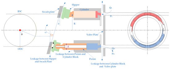
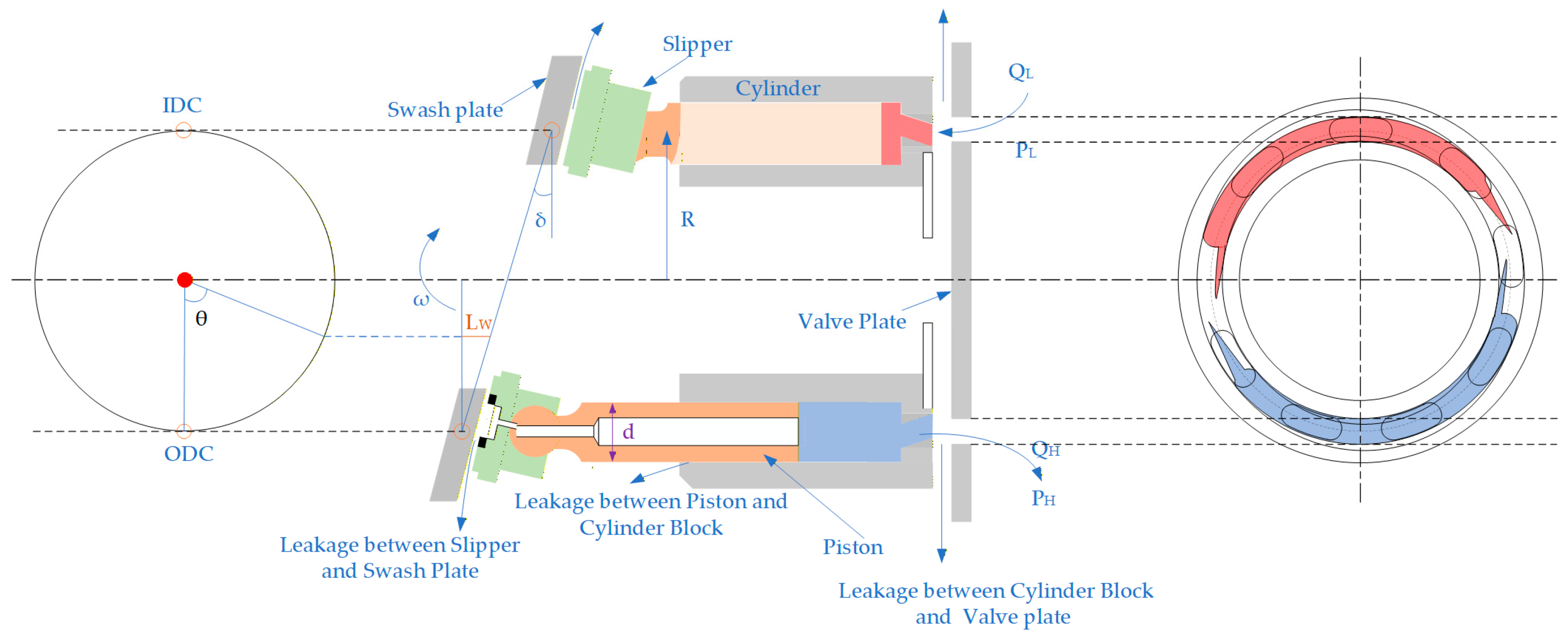
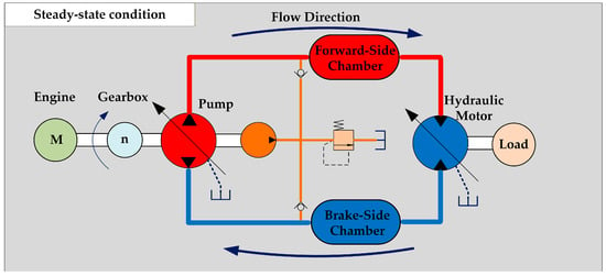
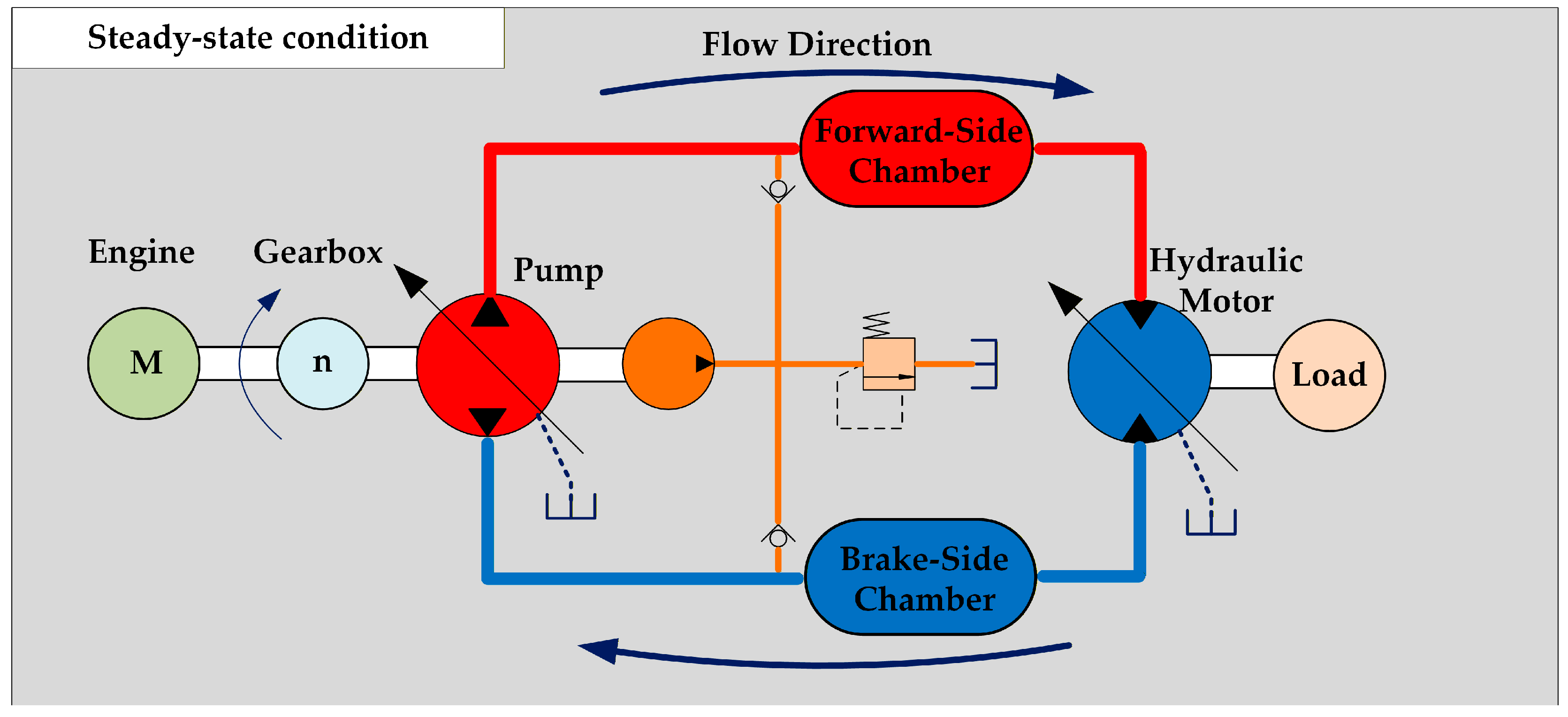
The core research object of this paper is a 180 mL/r closed-type axial piston pump equipped for the closed traveling system of cotton pickers. As the core power component of the closed traveling hydraulic system, the piston pump undertakes power transmission and transient response tasks under full operating conditions. A schematic diagram of the main structure of the piston pump is shown in Figure 1, and the key structural parameters are listed in Table 1. The working principle of the pump in the closed traveling hydraulic system of cotton pickers is illustrated in Figure 2. The system mainly consists of an engine, a closed-type axial piston pump, a traveling hydraulic motor, a charging unit, an advancing-side chamber, a braking-side chamber, and the working load. The engine drives the main pump to supply high-pressure oil to the system, and the driving and speed regulation of the traveling load are realized through the closed oil circulation between the main pump and the motor. The charging unit is used to compensate for system leakage flow and maintain a stable pressure on the low-pressure side.
Figure 1.
Schematic diagram of the piston pump structure.
Table 1.
Structural parameters of the piston pump.
Figure 2.
Hydraulic schematic of the cotton picker.
2.2. Cavitation Model and CFD Simulation Model
Cavitation modeling in axial piston pumps requires simultaneous description of gas–liquid two-phase flow and interphase mass transfer. At the multiphase flow framework level, the Euler–Euler approach is more suitable than the Euler–Lagrange method for characterizing dispersed gas-phase flow with high volume fractions within the complex flow structure of the valve plate pair. In this paper, a homogeneous mixture model under the Euler–Euler framework is adopted, assuming that the gas and liquid phases share a common velocity field and pressure field. The continuity and momentum equations of the mixture are given as follows:
where ρm denotes the mixture density, t represents time, u is the mixture velocity vector, p stands for pressure, and μm is the dynamic viscosity of the mixture. Regarding the mass transport model, common approaches proposed in the literature include the full cavitation model (FCM) proposed by Singhal et al. [25], the Zwart–Gerber–Belamri (ZGB) model [26], and the Kunz model [27]. Among these, the FCM comprehensively considers two types of phase transition processes: vaporous cavitation and non-condensable gas (NCG) desorption. It exhibits better physical authenticity for gaseous cavitation dominated by dissolved gas precipitation in hydraulic oil and has been widely adopted in flow simulations of hydraulic components [28]. Considering that in the cotton harvester emergency braking scenario focused on in this study, the hydraulic oil temperature is maintained at 20–40 °C, which is significantly lower than the temperature corresponding to its vapor pressure, the cavitation phenomenon is primarily dominated by the desorption of dissolved non-condensable gases rather than vaporous cavitation. Consequently, the Singhal full cavitation model is adopted in this paper, whose governing equations are presented as follows [29]:
where ρg is the gas-phase density, αg is the gas volume fraction, Re is the evaporation source term, and Rc is the condensation source term. When the local pressure is lower than the air separation pressure, Re dominates and gas precipitates; when the pressure recovers above the separation pressure, Rc dominates and gas redissolves. The turbulent characteristics of the flow field are solved using the RNG k-ε turbulence model. The RNG k-ε model introduces an additional strain rate term in the dissipation rate equation via the renormalization group method, which shows stronger capability in capturing flow with high strain rate, rotation effects, and near-wall flow separation [29], This makes it suitable for resolving complex flow features in the cylinder bore–valve plate interface region in this study, such as high-speed jets, wall-attached vortices, and flow separation. The main simulation parameters are listed in Table 2.
Table 2.
Main simulation parameters.
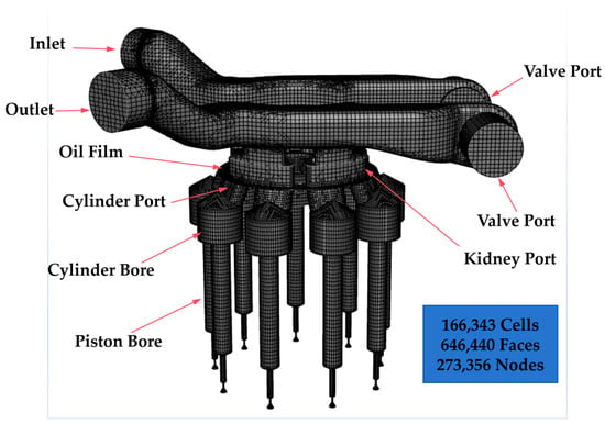
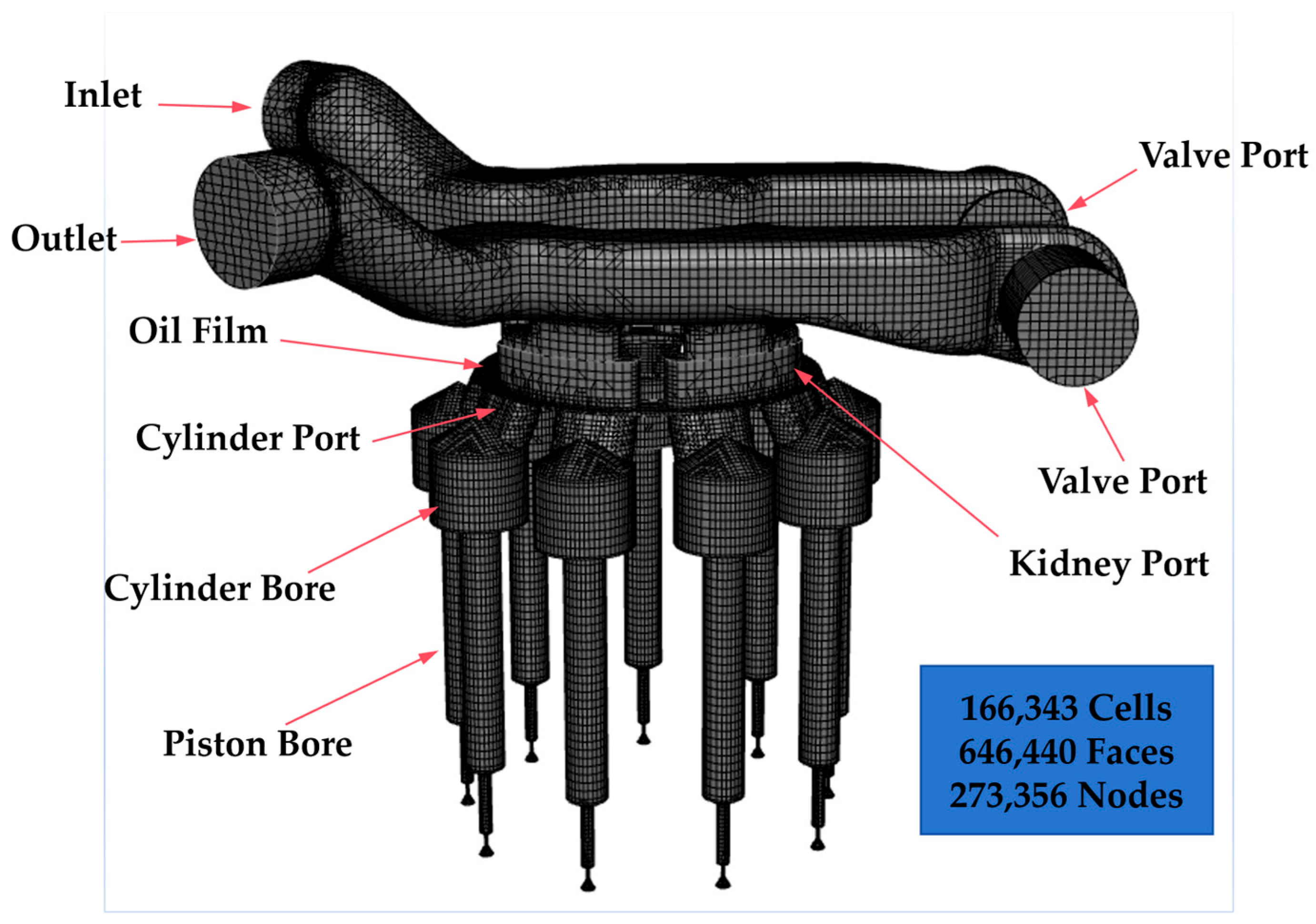
The fluid computational domain of the piston pump is divided into four subdomains: inlet passage, outlet passage, valve plate passage, and piston chamber, as shown in Figure 3. Cartesian structured grids are adopted for static domains such as the inlet passage, outlet passage, and valve plate passage. For the dynamic piston chamber domain, which rotates with the cylinder block and reciprocates axially, a dedicated dynamic mesh template for rotating machinery is used. Flow field variable transfer between static and dynamic domains is realized via the fully implicit mismatched grid interface (IMGI). Local mesh refinement is applied to flow-complex regions, including the corners of the valve plate kidney slots and damping slots, as well as the cylinder bore–valve plate interface, to improve the solution accuracy of the local flow field and cavitation phase-change process. Core settings for the transient simulation are as follows: total simulation time of 0.3 s, 2700 times steps, 30 iterations per step, covering 10 complete rotation cycles, with results saved every 10 steps. Boundary conditions are set as: pressure inlet at the inlet, pressure outlet at the outlet, and no-slip wall boundary for all solid walls.
Figure 3.
CFD model of the piston pump.
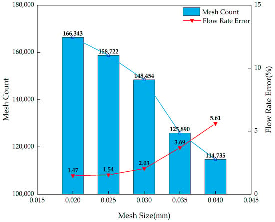
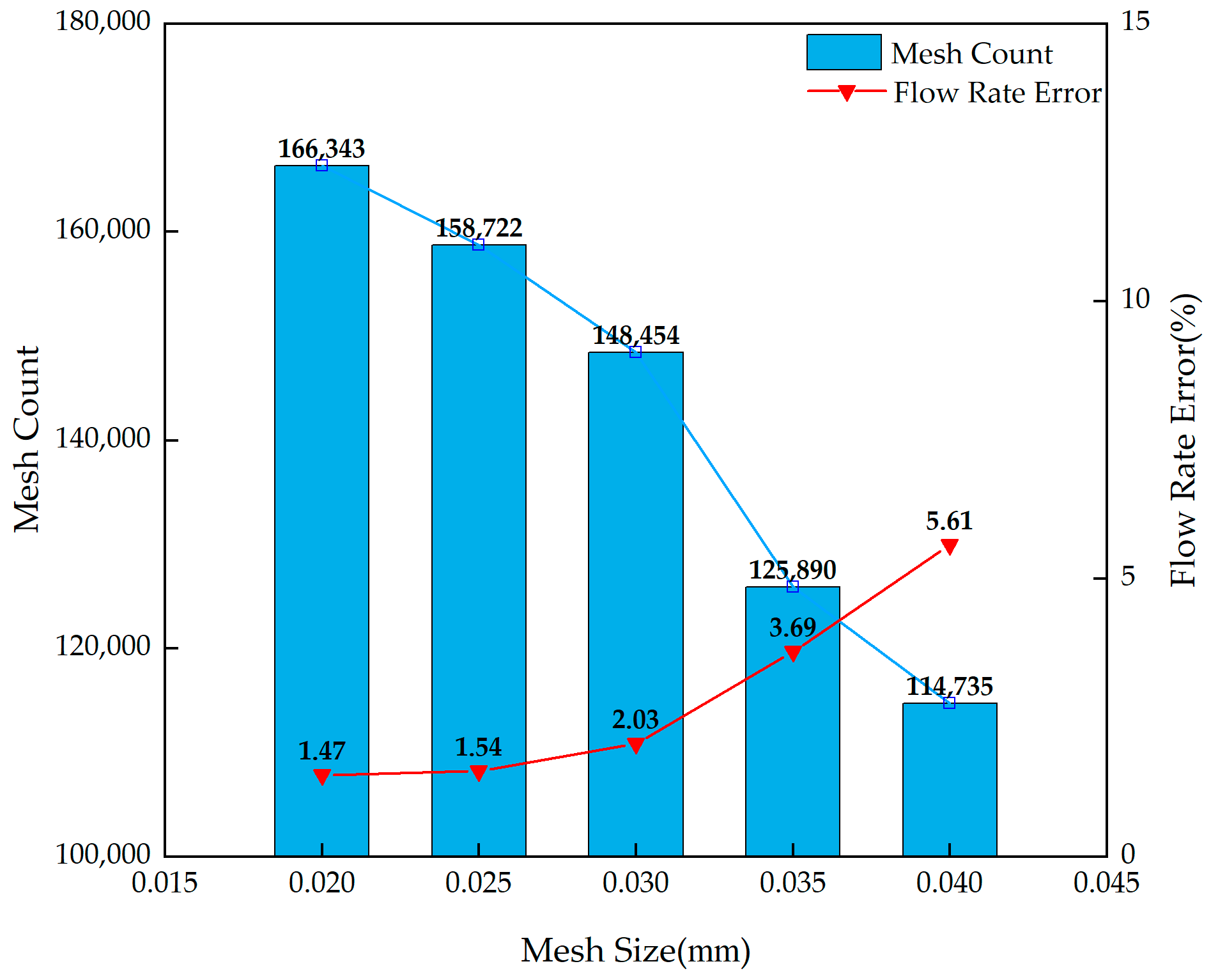
Mesh independence verification is carried out with the pump outlet flow rate as the core evaluation indicator. This index can directly reflect the internal flow characteristics and cavitation development intensity of the pump, and can also be effectively compared with subsequent experimental verification results. The grid flow rate error is defined as the relative deviation between the pump outlet flow rate obtained from CFD numerical simulation at each grid level and the theoretical analytical flow rate computed from the geometric displacement and instantaneous shaft speed of the pump. This metric isolates the contribution of grid discretization to flow rate prediction accuracy and serves as the quantitative criterion for selecting the optimal computational grid in the subsequent grid independence study. In this study, several groups of computational models with different grid sizes are established for mesh independence verification, and the results are shown in Figure 4. When the maximum grid size is reduced to 0.02 mm, the flow error remains at a low level. The calculation time of grid sizes 0.020 mm and 0.025 mm is similar, and the difference in flow error is small. To ensure high computational accuracy, the grid scheme with a maximum grid size of 0.02 mm is selected as the final simulation model in this study, with a total number of grid cells of approximately 166,000.
Figure 4.
Grid independence verification.
2.3. Description of Application Conditions
This study focuses on the actual working scenario of the closed traveling system of cotton pickers, clarifies the cavitation evolution characteristics inside the pump under emergency braking conditions, and identifies the core cavitation region.
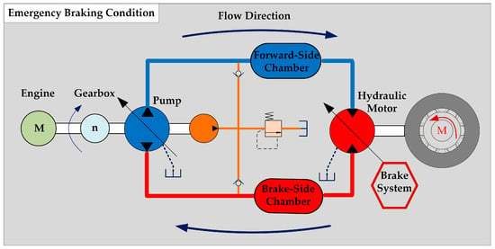
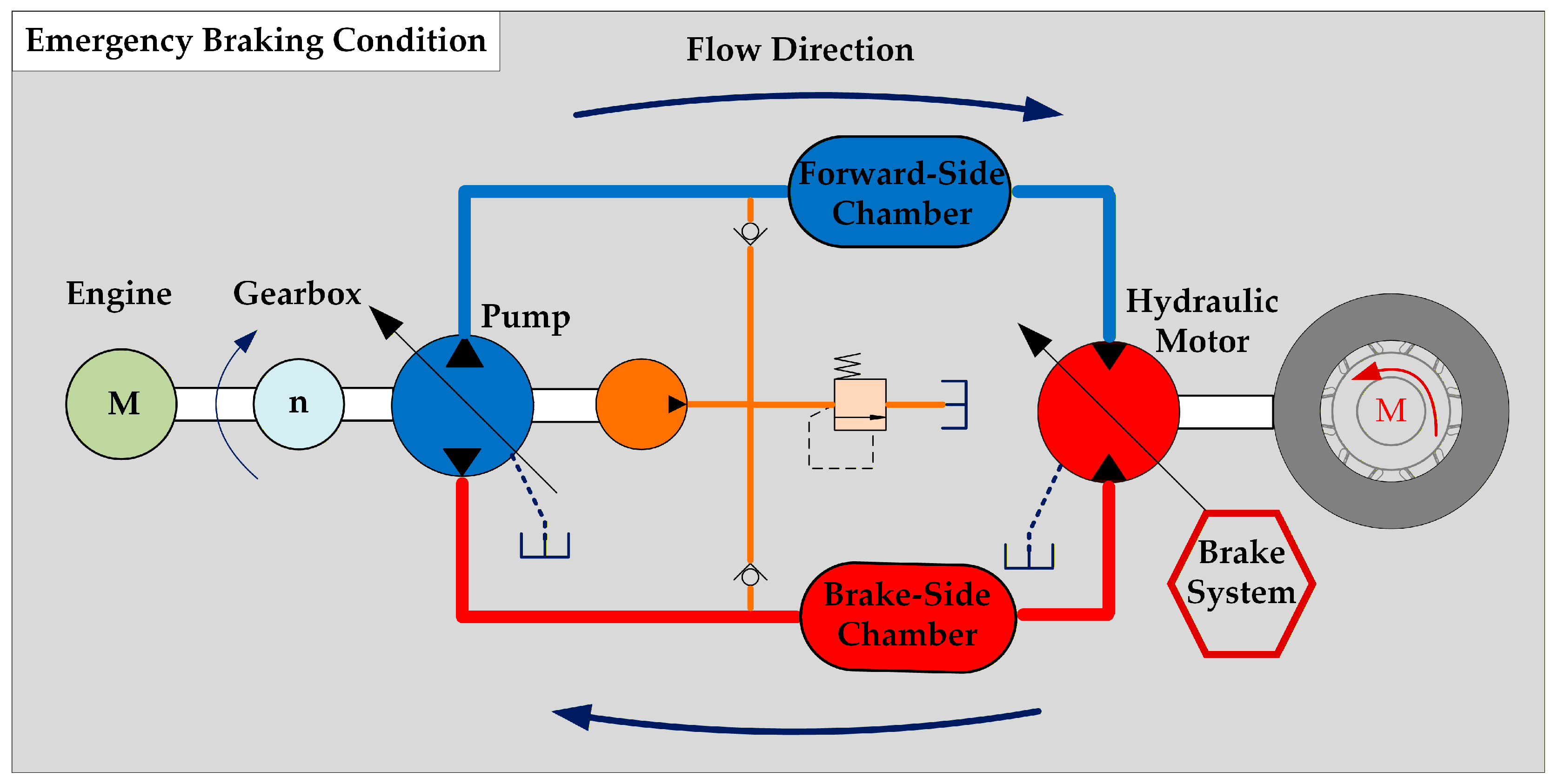
The physical mechanism of emergency braking and the boundary settings are summarized concisely below to avoid duplication with Section 1. When the cotton picker initiates emergency braking, the traveling motor switches into pump mode under the inertia of the machine, and the closed main pump is passively driven into motor mode; the braking-side pressure rises to the integrated relief-valve setting while the low-pressure side pressure collapses below the air separation pressure of the oil (0.03 MPa), liberating dissolved non-condensable gases and triggering cavitation, as illustrated in Figure 5.
Figure 5.
Schematic of emergency braking condition for the cotton picker.
The boundary conditions of the two working conditions in this study are set based on the theoretical variation laws derived from the measured data of the actual cotton picker traveling system. The specific settings are as follows:
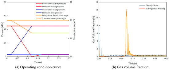
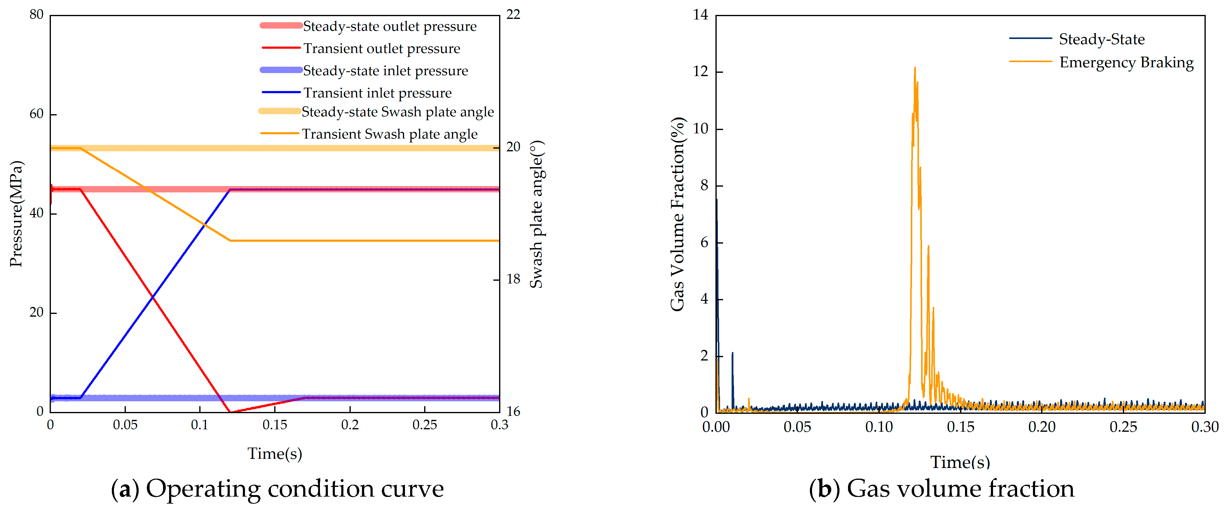
The steady-state basic condition is the rated full-load stable condition of the pump, corresponding to its maximum displacement and maximum load state. The boundary conditions are set as follows: swash plate inclination angle of 20°, charge pressure of 3 MPa, outlet pressure of 45 MPa, and constant pump speed of 2000 r/min, which provides a stable initial flow field for the transient condition. The emergency braking condition is a transient variable-load condition under emergency braking, corresponding to the transient process of rapid system pressure rise. The boundary conditions are set as follows: the pump first operates under the steady-state basic condition until the flow field is stable, and then transient excitation is applied. The charge pressure rises from 3 MPa to 45 MPa in a very short time, the outlet pressure drops from 45 MPa to 0 MPa and then recovers to 3 MPa, the swash plate inclination angle is adjusted from 20° to 18.6°, and the pump speed remains constant at 2000 r/min. The total simulation duration is 0.3 s, and the condition curves are shown in Figure 6a.
Figure 6.
Comparison diagram of gas volume fraction.
Figure 6b compares the time-varying curves of the overall gas volume fraction inside the pump under the two operating conditions. Under the steady-state condition, the gas volume fraction remains at a low level (<0.5%) with only slight fluctuations during the start-up stage. Under the emergency braking condition, the gas volume fraction reaches a peak of approximately 12% at 0.12 s and then drops rapidly, indicating that the cavitation intensity is significantly higher than that under the steady-state condition. This clearly reflects the strong excitation effect of transient pressure reversal on cavitation development. To identify the main cavitation region, the time-varying curves of gas volume fraction in the four subdomains of the pump are further analyzed, as shown in Figure 7.
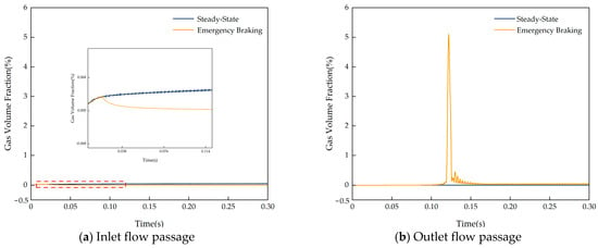
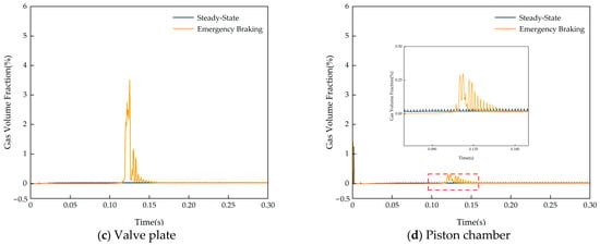
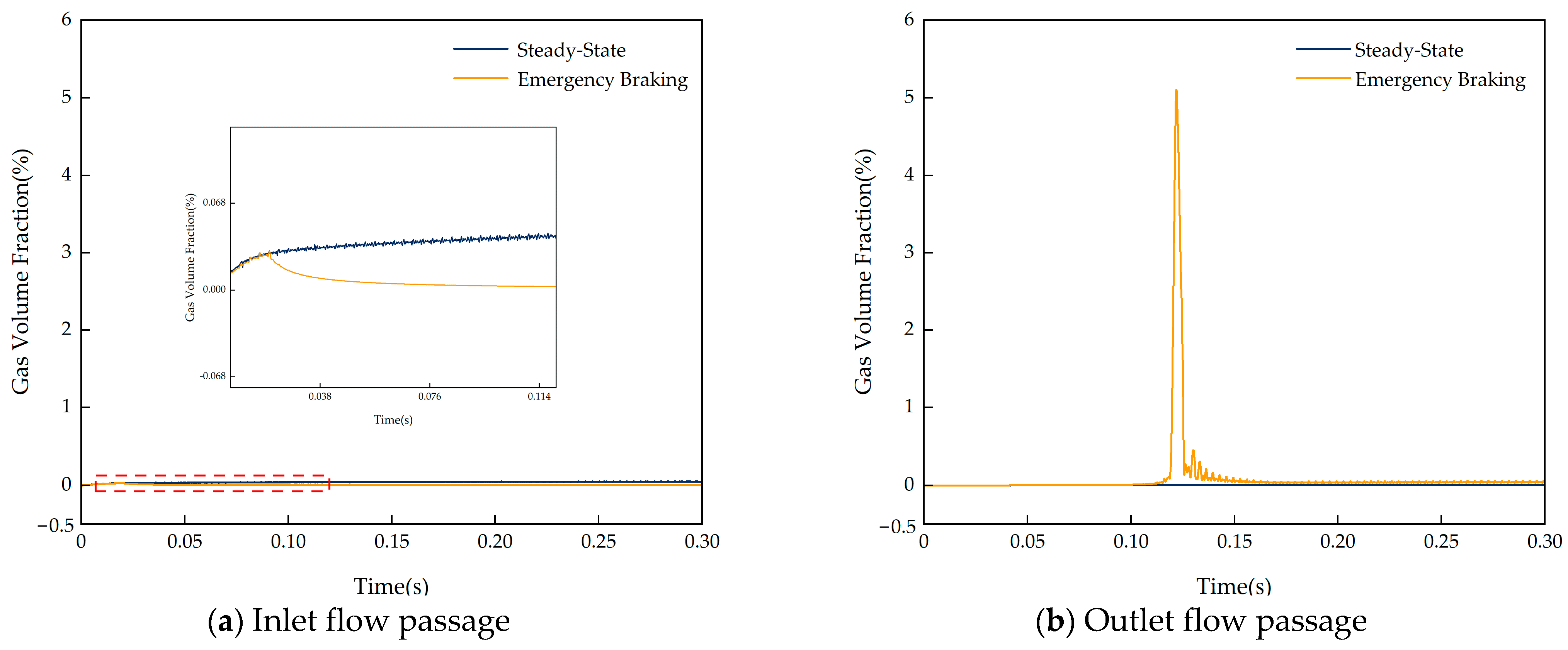
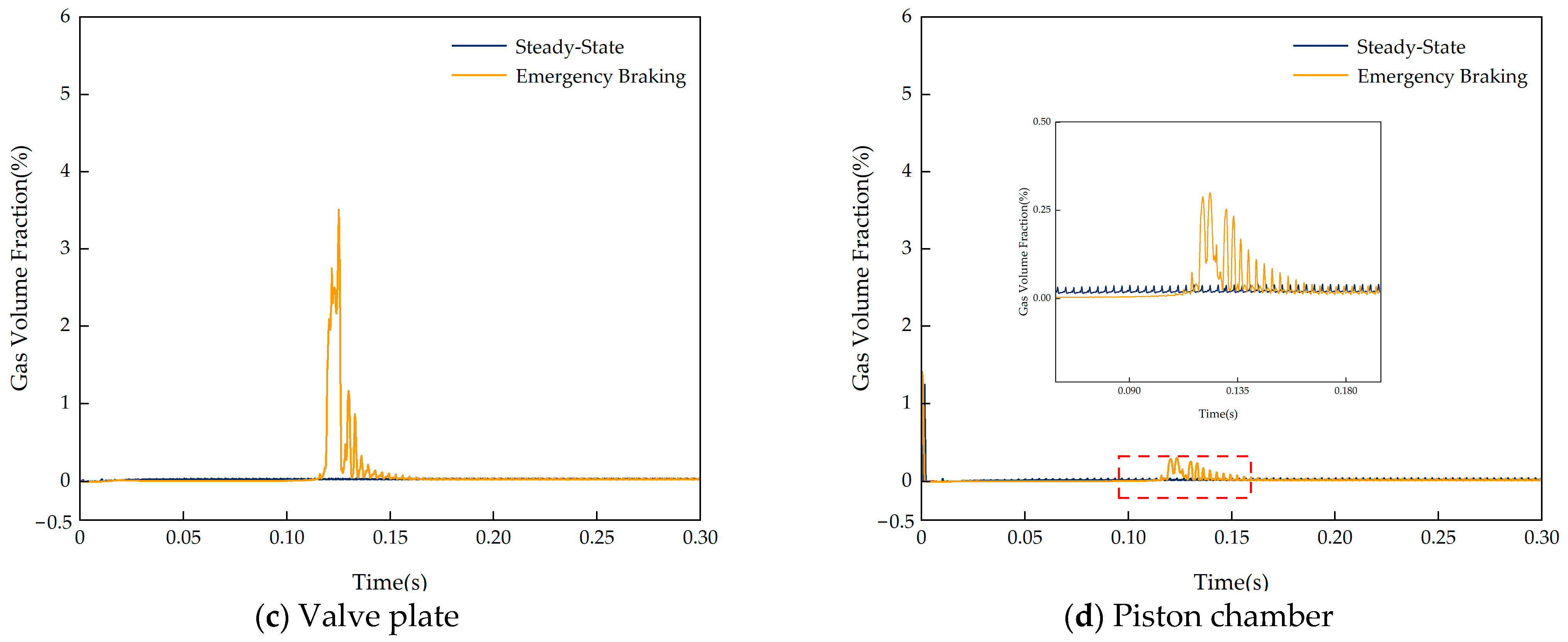
Figure 7.
Comparison diagram of gas volume fraction in flow passages.
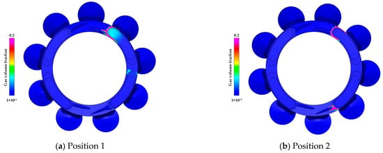
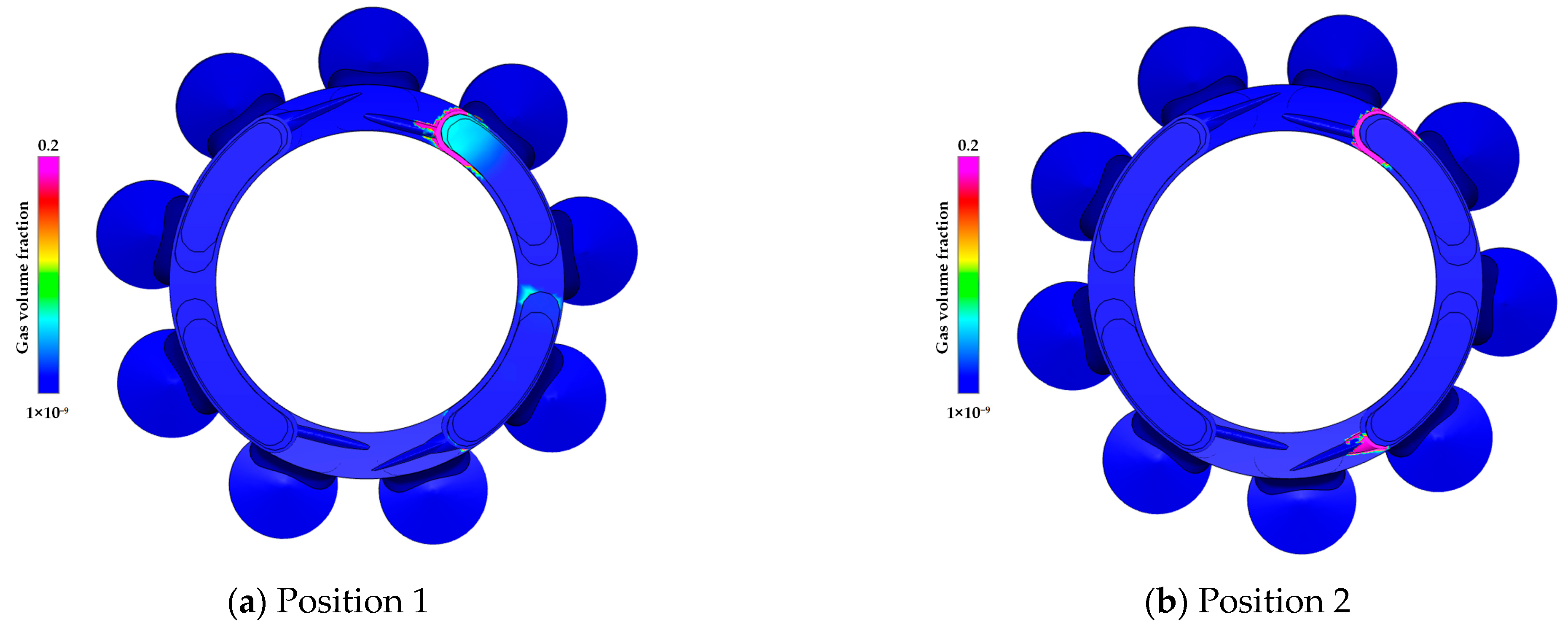
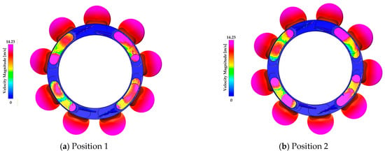
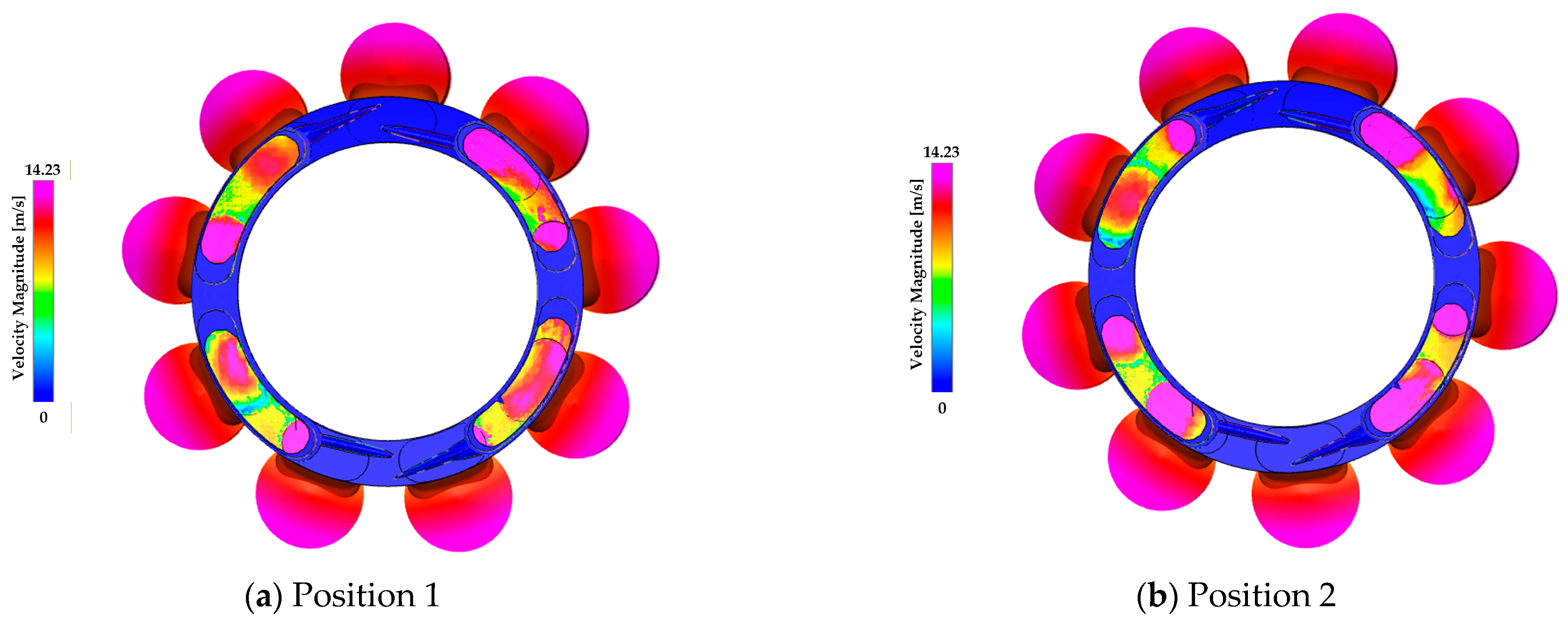
It can be observed from Figure 7 that the cavitation evolution in different subdomains exhibits obvious spatial distribution differences under emergency braking conditions. The outlet passage shows an instantaneous sharp peak in gas volume fraction, which is synchronized with the sudden drop in pump outlet pressure. This is caused by the precipitation of dissolved gas as the oil pressure falls below the air separation pressure in a short time. The gas volume fraction in this region decreases rapidly with the recovery of system pressure, resulting in a short cavitation duration. The cylinder–valve plate pair corresponding to the valve plate passage is the core motion pair that accomplishes the oil suction and discharge distribution in the axial piston pump, and is also the most concentrated region of cavitation in this study. Under emergency braking, the gas volume fraction in this region shows multi-peak oscillation between 0.10 and 0.15 s, with a maximum peak of approximately 3.5%. The oscillation duration is significantly longer than that in the outlet passage, and it gradually returns to the steady-state level only after 0.20 s. The peak gas volume fraction appears at 0.12 s. The contours of gas volume fraction and velocity distribution in the valve plate region at this moment are shown in Figure 8 and Figure 9, respectively.
Figure 8.
Cavitation location contour inside the pump.
Figure 9.
Velocity distribution contour inside the pump.
It can be clearly seen from the contour distribution in Figure 8 that cavitation bubbles are highly concentrated in the narrow annular region at the interface between the valve plate and the cylinder bore, rather than in the center of the outlet passage or inside the piston chamber. This spatial localization characteristic indicates that the dominant cause of cavitation is not global low pressure, but local static pressure reduction induced by the local flow structure.
It can be clearly seen from the contour distribution in Figure 9 that a distinct high-speed flow exists in the narrow annular region at the interface between the valve plate and the cylinder bore, with a local peak velocity reaching 14.23 m/s. The sharp acceleration of the fluid here induces a drastic drop in local static pressure, which is the core cause of concentrated cavitation in this region. Moreover, the cavitation distribution shows dynamic evolution characteristics with the periodic variation in the high-speed flow zone.
Specifically, during the transient pressure reversal under emergency braking, a natural right-angle abrupt change exists in the flow cross-section between the cylinder bore and the kidney groove of the valve plate. Driven by the transient pressure difference, this structural feature induces local throttling and high-speed jets in this region. After impinging on the cylinder bore wall and the valve plate passage wall, the jet forms a wall-attached vortex structure. The local static pressure in the vortex core further drops below the air separation pressure of the oil, triggering the precipitation of dissolved non-condensable gases. Accordingly, this study preliminarily proposes a positive feedback coupling chain that governs cavitation in the cylinder bore region under emergency braking. The chain proceeds sequentially from abrupt flow cross-section change, transient throttling jet, and wall-attached vortex formation to low pressure in the vortex core, dissolved gas precipitation, and eventually sustained cavitation.
Two key points should be emphasized: First, under emergency braking conditions, the pump outlet pressure has dropped to near 0 MPa at t = 0.12 s, placing the entire system at an extremely low-pressure level. Consequently, the conventional cavitation number criterion based on steady-state far field pressure is no longer applicable [30], and the global static pressure contours are ineffective in distinguishing incipient cavitation regions from the overall low-pressure area of the system.
Second, the aforementioned mechanism chain is currently inferred solely based on the spatial distribution characteristics of the CFD gas volume fraction contours, and its validity remains to be verified through independent flow field visualization experiments. Considering these two points, Section 3 designs and conducts a PIV internal flow field visualization experiment based on the Reynolds similarity criterion. Through direct observation of the vortex structure and velocity distribution in the cylinder bore–valve plate interface region, this experiment experimentally validates the aforementioned mechanism hypothesis and provides a reliable theoretical basis for the structural optimization presented in Section 4.
3. Verification of the Simulation Model
To verify the reliability and computational accuracy of the CFD numerical model for the closed-circuit axial piston pump established above, experimental verification is carried out in this section from two perspectives: the overall macro performance of the pump and the local flow field in the core region of the valve plate pair. Limited by experimental conditions, the extreme transient emergency braking condition is difficult to fully reproduce on the test rig. Therefore, the overall performance under steady high-load conditions is tested to confirm the model’s predictive capability for the macro flow characteristics of the pump. Then, a PIV internal flow field visualization experiment is adopted to verify the calculation accuracy of the local flow field in the core cavitation region.
3.1. Test Rig Verification
Volumetric efficiency is a key macroscopic indicator reflecting the internal flow characteristics and operating performance of a closed-circuit axial piston pump. The occurrence of cavitation directly leads to a reduction in the pump output flow and a decrease in volumetric efficiency. In this section, the overall computational accuracy of the numerical model is verified by comparing the experimental test and simulation results of the pump volumetric efficiency under rated high-load steady-state conditions with different charge pressures and rotational speeds.
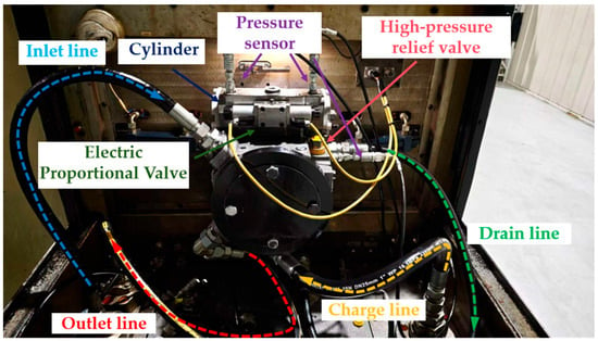
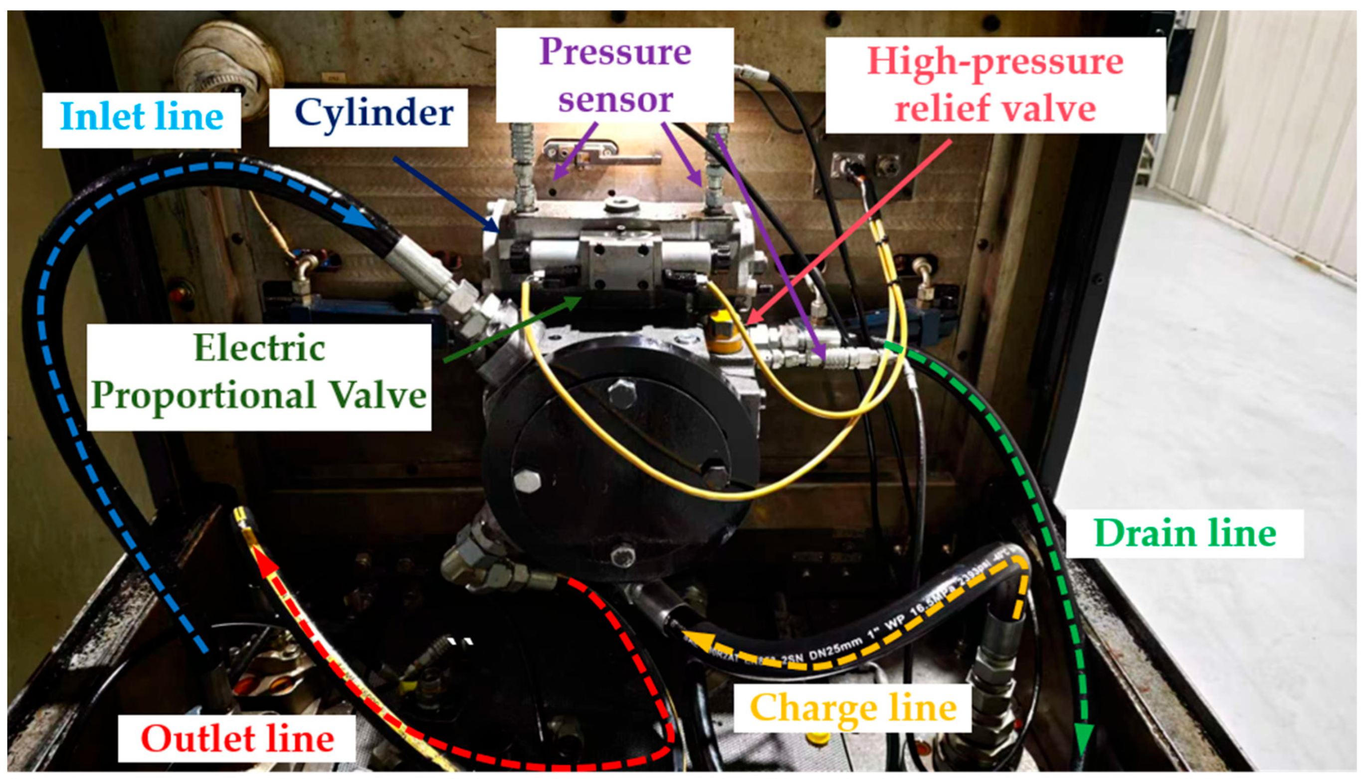
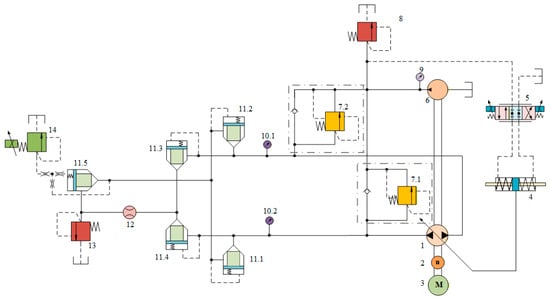
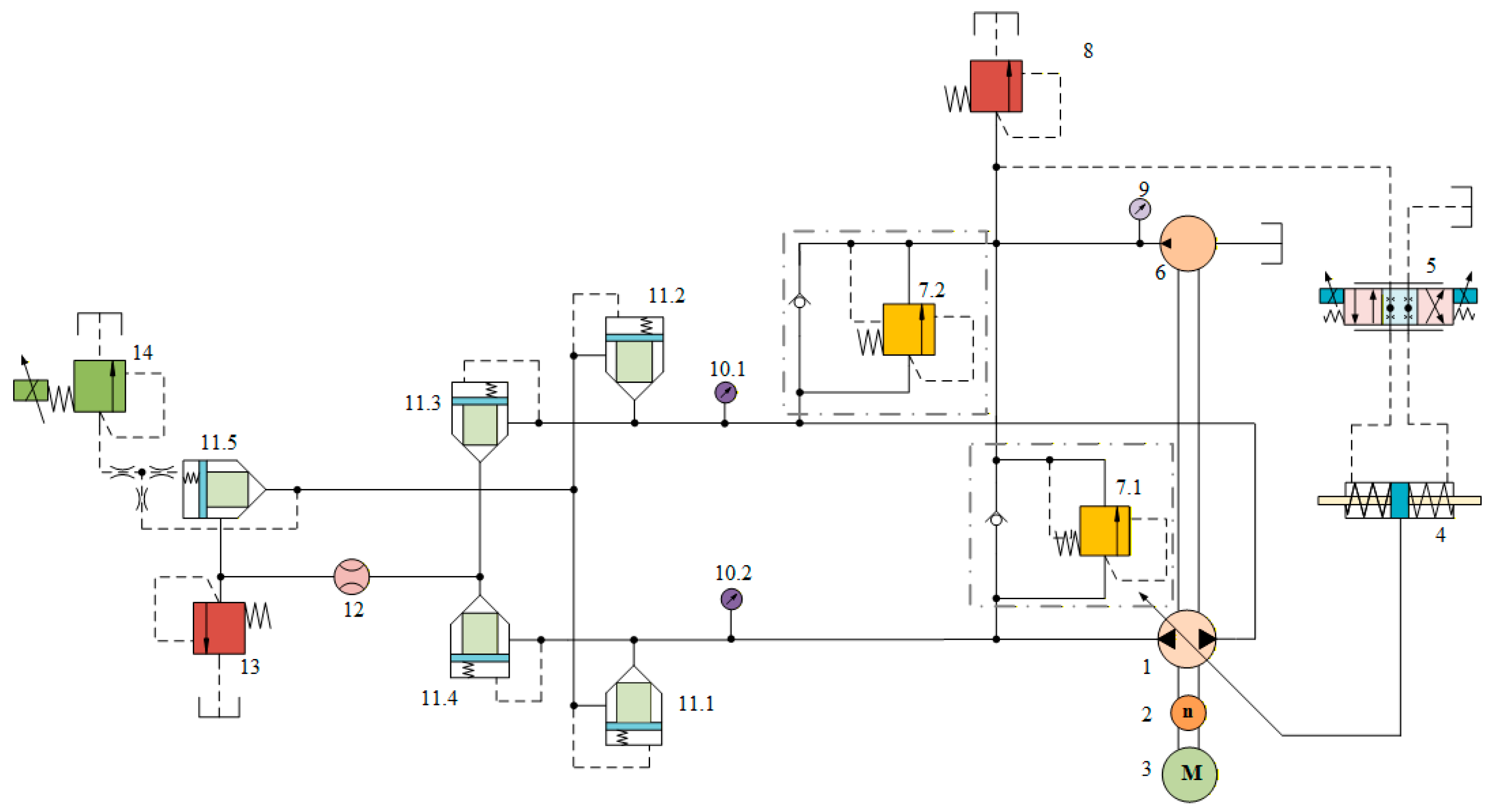
Tests were carried out on a 180 mL/r closed-circuit piston pump using a medium-power closed-circuit piston pump performance test rig. The test rig and test principle are shown in Figure 10 and Figure 11, respectively. The functions of each component in Figure 11 are as follows: 1 tested pump; 2 speed sensor; 3 electric motor; 4 displacement cylinder, which adjusts the swash plate inclination of the main pump to achieve displacement variation; 5 electric proportional directional valve, which realizes electronically controlled displacement adjustment of the main pump; 6 charge pump, which provides charge oil and control oil supply; 7 high-pressure relief valve, which realizes system loading and pressure stabilization; 8 charge relief valve, which maintains stable charge pressure; 9, 10 pressure sensors; 11 check valve; 12 flow sensor; 13 direct-acting safety relief valve, which provides circuit overpressure protection; 14 loading valve, which provides an adjustable load for performance tests under different pressures. Detailed information on the valve assembly is listed in Table 3.
Figure 10.
Schematic of closed-circuit pump test bench.
Figure 11.
Schematic diagram of the closed-circuit pump test bench.
Table 3.
Experimental test parameters.
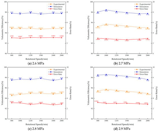
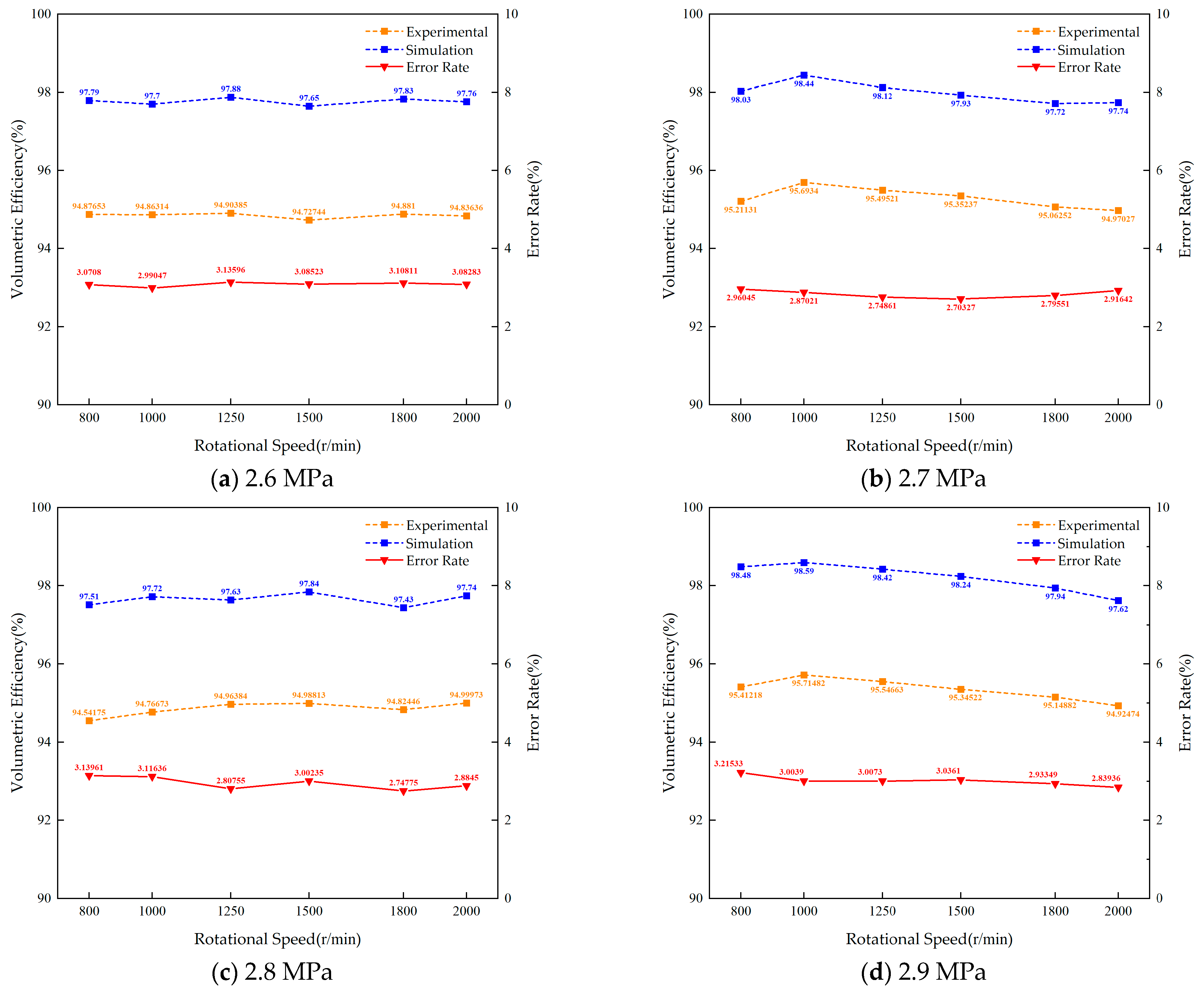
The tests were conducted under the steady high-load condition with the rated outlet pressure of 40 MPa. Four charge pressure levels were set: 2.6 MPa, 2.7 MPa, 2.8 MPa, and 2.9 MPa. For each charge pressure, six pump speeds were tested: 800, 1000, 1250, 1500, 1800, and 2000 r/min, covering the typical operating speed range of the pump. Each working condition was tested three times repeatedly, and the average value was taken as the final measured data. A comparison between the experimental and simulated volumetric efficiency of the pump is shown in Figure 12.
Figure 12.
Comparison diagram of volumetric efficiency.
In terms of the overall trend, the variation laws of volumetric efficiency obtained by simulation under the four charge pressures are consistent with the experimental results: the volumetric efficiency of the pump reaches its peak in the speed range of 1250–1500 r/min, and decreases to different degrees at the low speed of 800 r/min and the high-speed of 2000 r/min, which conforms to the inherent variation characteristics of axial piston pumps. Meanwhile, the overall volumetric efficiency shows an upward trend with the increase in charge pressure. This is because a higher charge pressure can effectively suppress the formation of low-pressure zones inside the pump, thus reducing leakage losses and cavitation risks.
In terms of numerical agreement, the volumetric efficiency deviations between simulation and experiment under the four charge pressures are all controlled within 3.5%, and the two curves show high coincidence. The above results indicate that under steady high-load conditions, the numerical model established in this paper can accurately predict the macroscopic operating performance of the closed-circuit axial piston pump and possesses favorable overall calculation accuracy.
3.2. PIV Flow Field Measurement and Validation of the Simulated Flow Field
Section 2 has shown that the core cavitation region inside the pump under the extreme emergency braking condition is the interface area between the valve plate and the cylinder bore of the plunger cylinder. To further verify the calculation accuracy of the numerical model for the internal flow field in this core region and, from an experimental perspective, validate the cavitation mechanism proposed in Section 2.3, this study adopts Particle Image Velocimetry (PIV) to conduct flow field visualization experiments in the valve plate pair region.
Owing to the fully enclosed metallic structure of the axial piston pump, direct internal flow visualization cannot be realized. Furthermore, the actual flow velocity within the target valve plate pair region is relatively high, exceeding the measurement range of conventional PIV systems. Accordingly, in accordance with the Reynolds similarity criterion, a fully transparent test model with geometrically enlarged dimensions was designed and manufactured via stereolithography (SLA) 3D printing using high-transparency photosensitive resin. All key flow-related structures in the model, including the piston diameter, valve plate flow channels, cylinder bores, and damping grooves, were proportionally scaled in keeping with the original simulation model. The flow in the valve plate pair region is viscous-dominated incompressible flow. Therefore, the Reynolds similarity criterion is adopted to ensure the dynamic similarity of the flow field between the prototype and the test model, the Reynolds numbers of the prototype and the model are equal, which is expressed as:
where ρ is the fluid density, u is the characteristic flow velocity, l is the characteristic length taken as the piston diameter, and μ is the dynamic viscosity of the fluid.
To ensure dynamic similarity of the flow field between the simulation prototype and the test model, the condition Re = Rm must be satisfied, where the subscript e denotes the simulation prototype and m denotes the test model. Water, with superior optical transparency, was selected as the test medium. Based on the similarity criterion, the calculated inlet velocity of the test model is 0.0995 m/s. Table 4 lists the key parameters of the simulation prototype and the test model.
Table 4.
Corresponding parameters of simulation and experimental models.
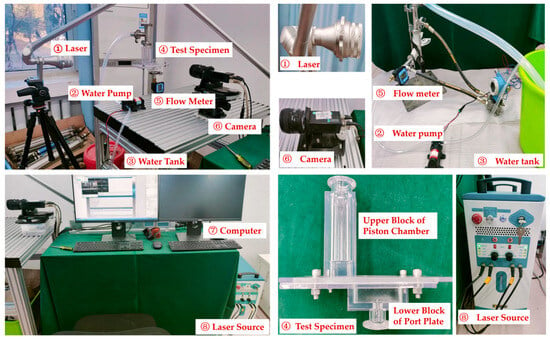
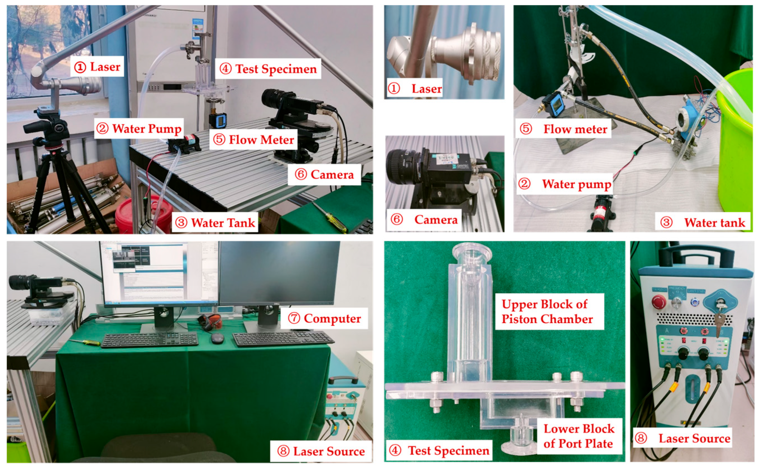
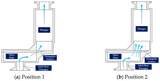
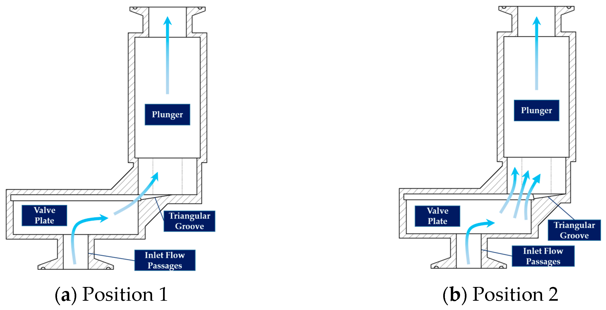
The PIV measurement system consists of a hydraulic circuit module, a pulsed laser module, a high-speed camera module, and a data processing module. The test rig arrangement is shown in Figure 13. Combined with the simulation results under the extreme emergency braking condition, two typical relative positions between the piston and the valve plate at the cavitation peak moment 0.12 s are selected as observation positions. Position 1: the piston front end contacts the root of the damping groove; Position 2: the piston rear end contacts the head of the damping groove. Transparent test models corresponding to these relative positions are fabricated as shown in Figure 14.
Figure 13.
Test bench layout.
Figure 14.
Model schematic.
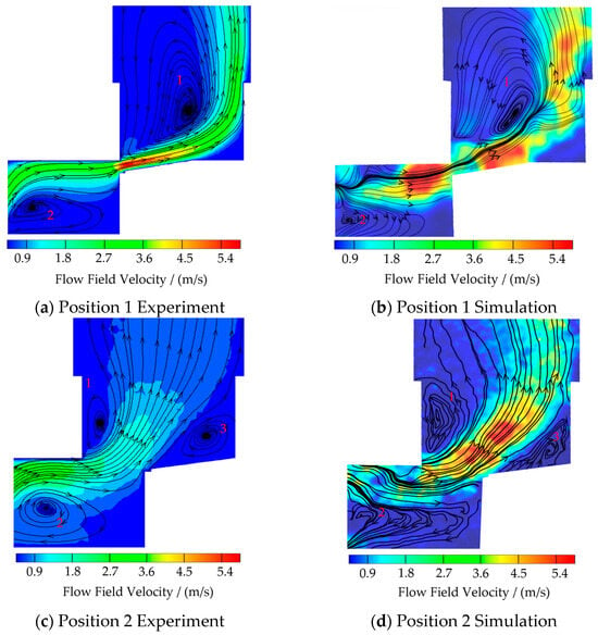
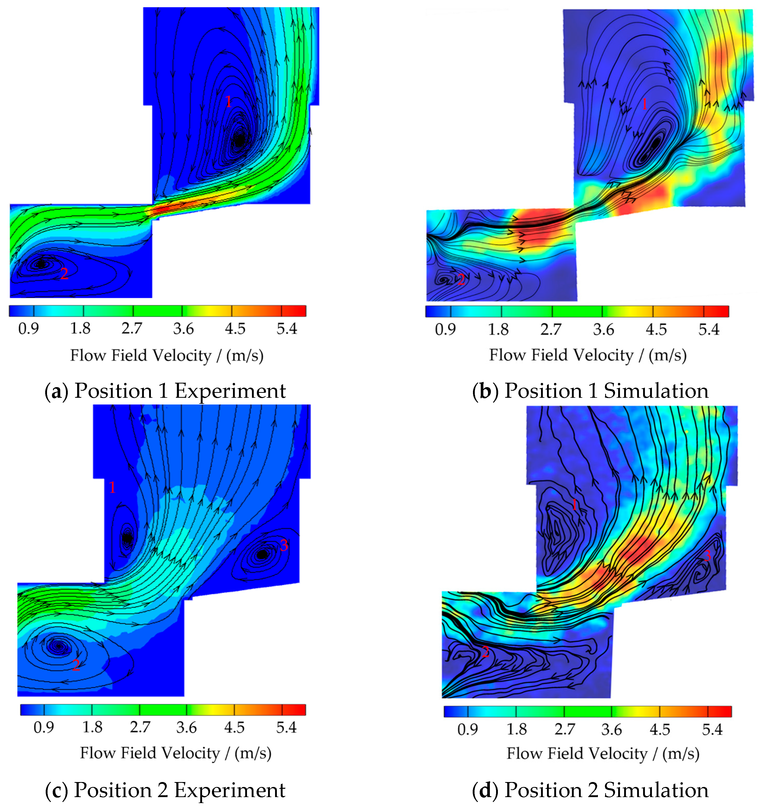
The comparison of flow streamlines between the simulation and experimental results for the two observation positions is shown in Figure 15.
Figure 15.
Flow velocity streamlines.
From a qualitative comparison of flow field structures, when the piston is at Position 1, both experimental and numerical results exhibit a typical dual-vortex flow structure. As fluid passes through the damping groove, flow velocity increases significantly due to the throttling effect. After impinging on the valve plate passage wall and the piston chamber wall, the high-speed jet forms separate vortex structures in two distinct regions. When the piston moves to Position 2, the jet angle deflects noticeably as the flow area at the groove opening enlarges. The vortex scale inside the piston chamber decreases considerably, while a new vortex structure emerges on the opposite side. The spatial distribution of vortices, streamline patterns, and flow field evolution obtained from numerical simulation are highly consistent with the PIV measurements.
From a quantitative comparison of velocity distribution, statistical comparison was conducted on the average velocity at characteristic cross-sections for the two observation positions. The relative errors of average velocity between simulation and experiment are both below 10%, showing good agreement with the 40:1 velocity scaling ratio determined by the Reynolds similarity criterion.
The dual-vortex structure directly observed in the PIV experiments agrees well with the throttling–jet–vortex-dominated mechanism inferred from the CFD gas volume fraction contours in Section 2.3. This experimentally confirms that wall-attached vortices serve as the core flow field carrier for sustained cavitation under this working condition. The conclusion provides a mechanical basis for the structural optimization of the cylinder bore in Section 4, which focuses on suppressing wall-attached vortices.
4. Structural Optimization
Section 2 has identified the cylinder bore–valve plate interface as the core cavitation region inside the pump under emergency braking conditions, and has preliminarily proposed that cavitation in this region is dominated by a local flow mechanism involving abrupt flow cross-section change, throttling jet, wall-attached vortex, local low pressure, and non-condensable gas precipitation. The PIV experiments in Section 3 have further experimentally verified the dual-vortex flow structure in this region. On the basis of the above mechanism, this section conducts targeted optimization research on the cylinder bore structure. Section 4.1 quantifies the regulation laws of three key geometric parameters of the cylinder bore on cavitation evolution through parametric transient CFD simulations. Section 4.2 establishes a multi-objective optimization model centered on transient limit eigenvalues, solves the Pareto optimal solution, and explains the mechanism of the optimized structure. Section 4.3 verifies the effectiveness and robustness of the optimized structure through multi-condition simulations.
4.1. Regulation Laws of Cylinder Bore Geometric Parameters on Cavitation Evolution
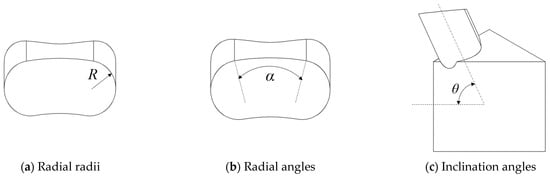
From the perspective of the flow structure characteristics of the valve plate pair, the transient flow behavior between the cylinder bore and the kidney-shaped groove of the valve plate is mainly governed by three geometric parameters in orthogonal dimensions, corresponding to the three key stages of the cavitation initiation chain identified in Section 2.3. The radial radius R determines the radial matching between the cylinder bore and the kidney-shaped groove as well as the abrupt change in flow cross-section, directly affecting the intensity of the transient throttling effect and relating to the cavitation incipient stage. The radial angle α characterizes the circumferential relative position between the piston axis and the damping groove of the valve plate, influencing the dynamic evolution of the effective flow area during emergency braking and relating to the full-cycle dynamic evolution of cavitation. The axial inclination angle θ corresponds to the axial profile of the cylinder bore flow passage, regulating the jet development and pressure recovery inside the bore. It acts as the controlling factor for the formation and development of wall-attached vortex structures and relates to the sustained development stage of cavitation.
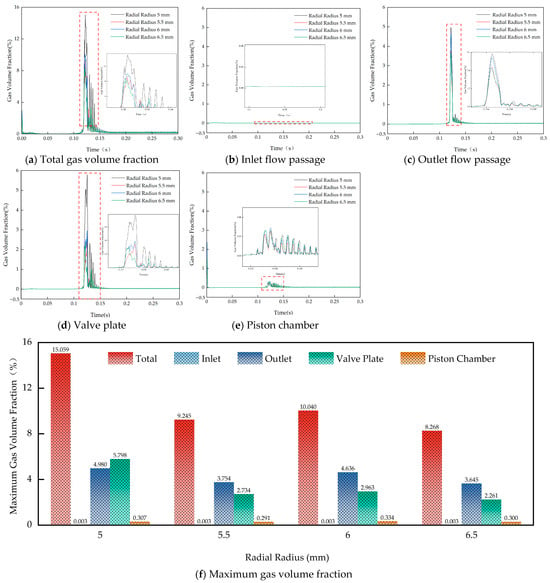
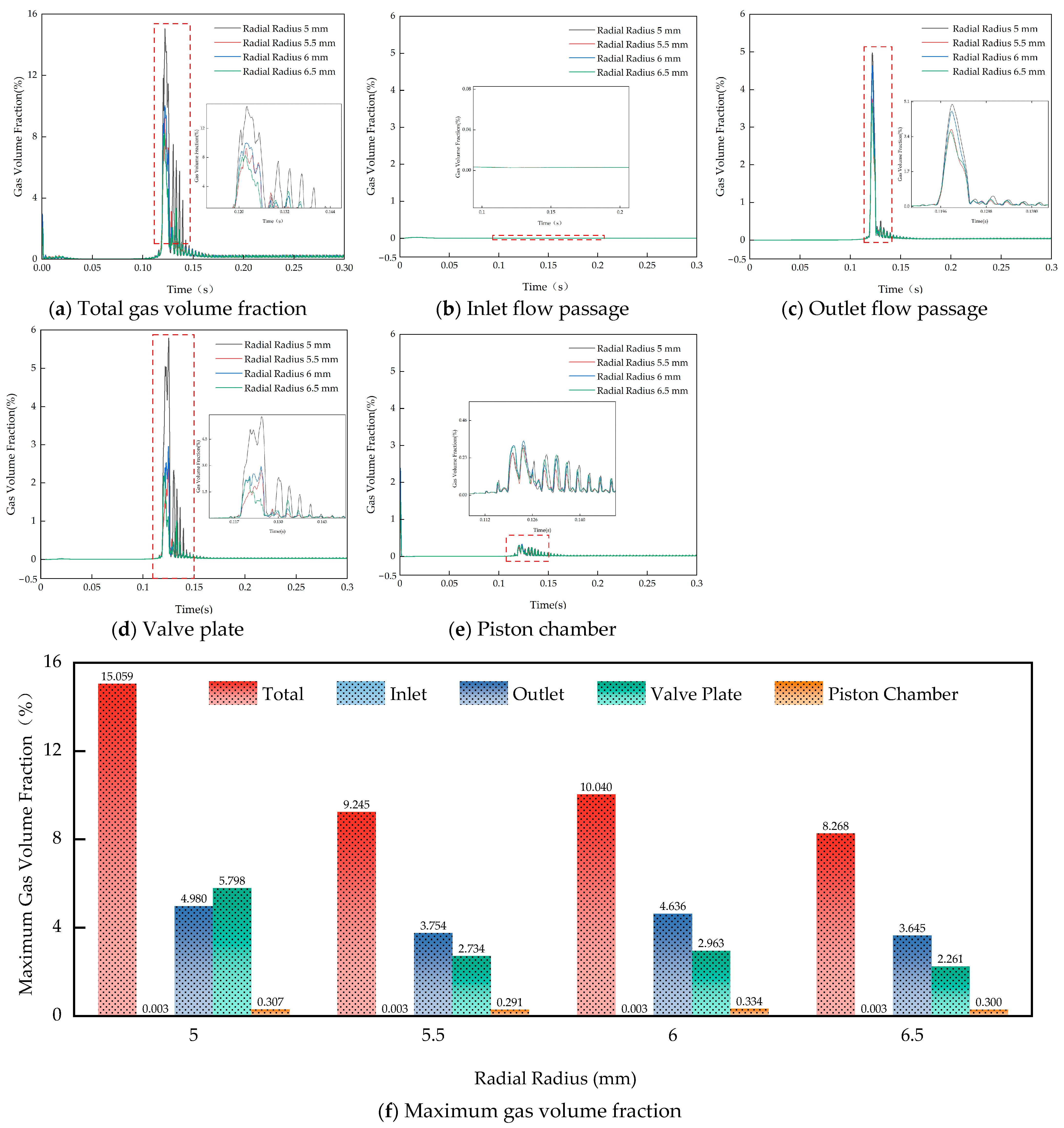
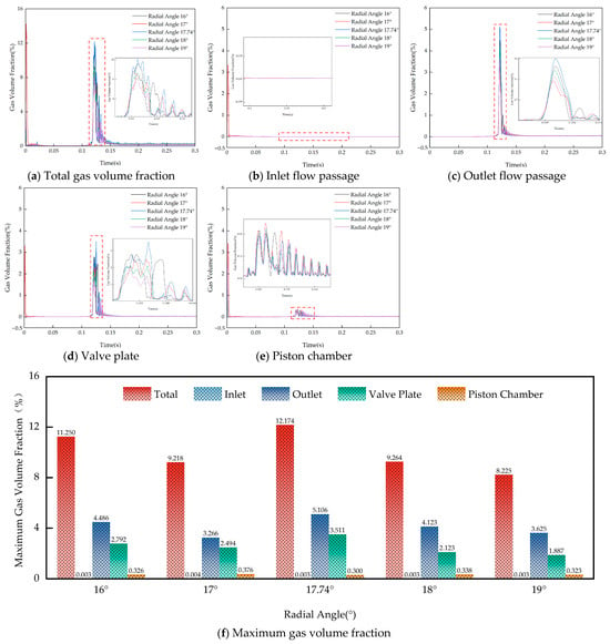
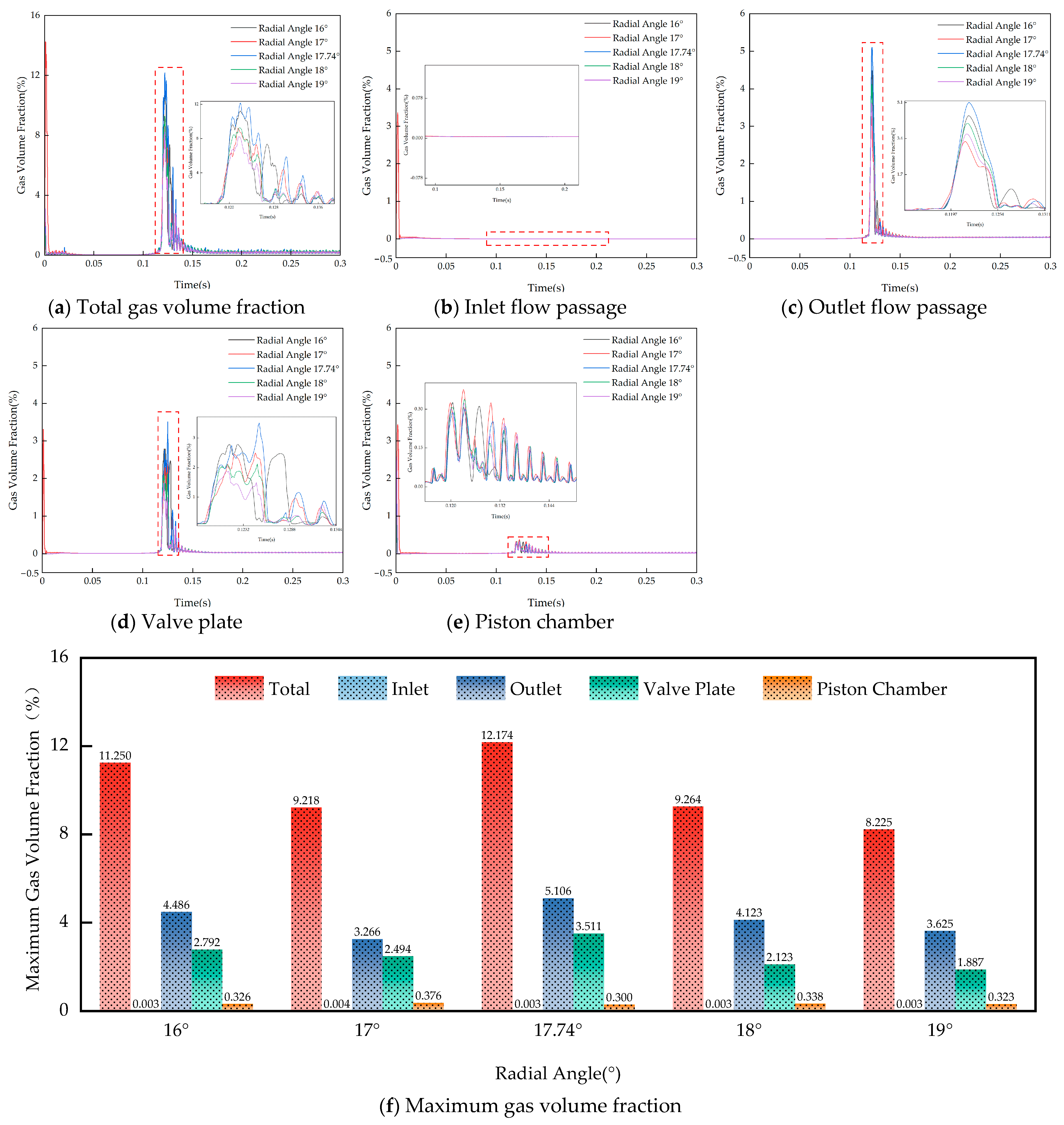
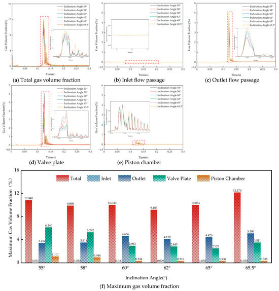
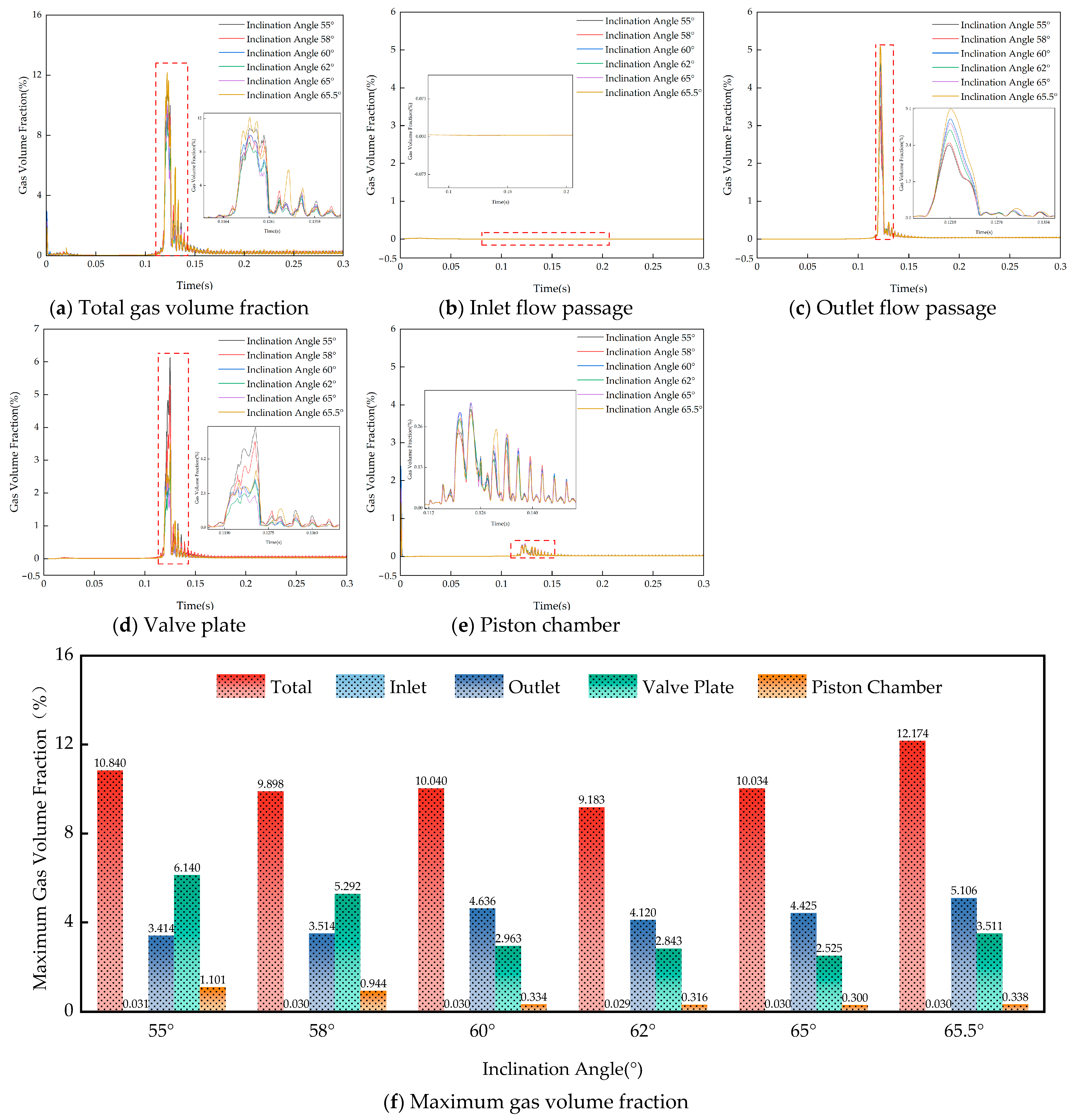
With respect to the above three parameters, fully parametric transient CFD simulations are carried out based on the baseline configuration with R = 6 mm, α = 17.74°, θ = 60°. The structural diagram is shown in Figure 16. The single-factor scanning ranges are as follows: R ∈ {5.0 mm, 5.5 mm, 6.0 mm, 6.5 mm}, α ∈ {16°, 17°, 17.74°, 18°, 19°}, θ ∈ {55°, 58°, 60°, 62°, 65°, 65.5°}. The boundary conditions and solution settings for each simulation are identical to those in Section 2. The simulation results are presented in Figure 17, Figure 18 and Figure 19, which show the time-varying curves and full-cycle peak values of the gas volume fraction in five subdomains: the whole flow domain, inlet passage, outlet passage, valve plate passage, and piston chamber.
Figure 16.
Schematic diagrams of various structural forms.
Figure 17.
Gas volume fraction in flow passages at different radial radii.
Figure 18.
Gas volume fraction in flow passages at different radial angles.
Figure 19.
Gas volume fraction in flow passages at different inclination angles.
Figure 17 shows that within the range of 5.0–6.5 mm, the peak total gas volume fraction generally decreases with increasing R, but rebounds locally to 0.1004 at R = 6 mm. This non-monotonic characteristic arises from the dual effects of flow cross-section matching: when R is small, severe radial mismatch produces the strongest throttling jet and the most severe cavitation; as R increases, the matching improves and throttling weakens. However, when R approaches the width of the kidney-shaped groove, the jet impingement angle changes, locally inducing secondary vortices that cause the gas fraction peak to rise again. Statistics for each subdomain reveal that more than 75% of transient cavitation is concentrated in the valve plate and outlet passage, confirming that throttling jets caused by abrupt flow cross-section changes are the core inducement of cavitation initiation under this working condition.
Figure 18 shows that the cavitation peak exhibits an asymmetric unimodal characteristic with respect to α with the peak occurring at α = 17.74°, which is 8.2% higher than that at 16° and 47.9% higher than that at 19°. This critical angle corresponds exactly to the configuration where the piston front end aligns with the root of the damping groove, the observed state at Position 1 in the PIV experiments in Section 3. At this position, the transient effective flow area is minimized, the throttling effect is strongest, and cavitation bubbles develop sufficiently. When deviating from this position, the flow area expands rapidly and the cavitation intensity decreases accordingly. This indicates that the valve plate pair phase designed for steady-state conditions may coincide with the most unfavorable position under emergency braking, and α should be taken as a working condition boundary constraint in subsequent optimization.
Figure 19 shows that, taking the valve plate passage as the evaluation index, the gas volume fraction peak generally decreases with increasing θ: it is 6.14% at 55° and drops to 2.53% at 65°, but rebounds to 3.51% at 65.5°. The overall domain gas volume fraction shows a non-monotonic trend because the cavitation concentration region migrates from the valve plate to the outlet passage as θ increases. This study focuses on local cavitation damage at the cylinder bore–valve plate interface, so the peak value in the valve plate is taken as the primary evaluation index. Physically, a moderate increase in θ transitions the cylinder bore toward a diverging profile, improving jet pressure recovery and suppressing the formation of wall-attached vortices. However, when θ exceeds approximately 65°, the divergence angle surpasses the critical value for boundary layer separation, which in turn induces new separation vortices and intensifies cavitation. Therefore, the optimal range of θ is approximately 62–65°.
In summary, the three sets of parametric simulations systematically quantify the cavitation regulation laws of key geometric parameters of the cylinder bore from three core stages: cavitation initiation, full-cycle dynamic evolution, and sustained development. The results verify the transient positive feedback coupling mechanism of throttling–jet–vortex–cavitation proposed in Section 2.3. Among them, the radial angle α corresponds to a circumferential porting position that the piston pump inevitably passes through during operation. It serves as a working condition boundary to be covered in optimization rather than an independently designable structural parameter. In contrast, the orifice fillet represented by radial radius R and the bore taper represented by axial inclination angle θ can suppress the throttling effect and wall-attached vortices, covering the two key stages of cavitation initiation and sustained development in the cavitation induction chain. Therefore, R and θ are determined as the core structural optimization variables. In addition, considering the interactive coupling effect among the three parameters, simple single-parameter optimization cannot yield a globally optimal solution. Subsequent research will adopt a multi-objective global optimization method for collaborative regulation.
4.2. Multi-Objective Optimization Design and Validation of Cylinder Bore Structure for Cavitation Suppression
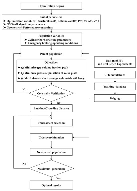
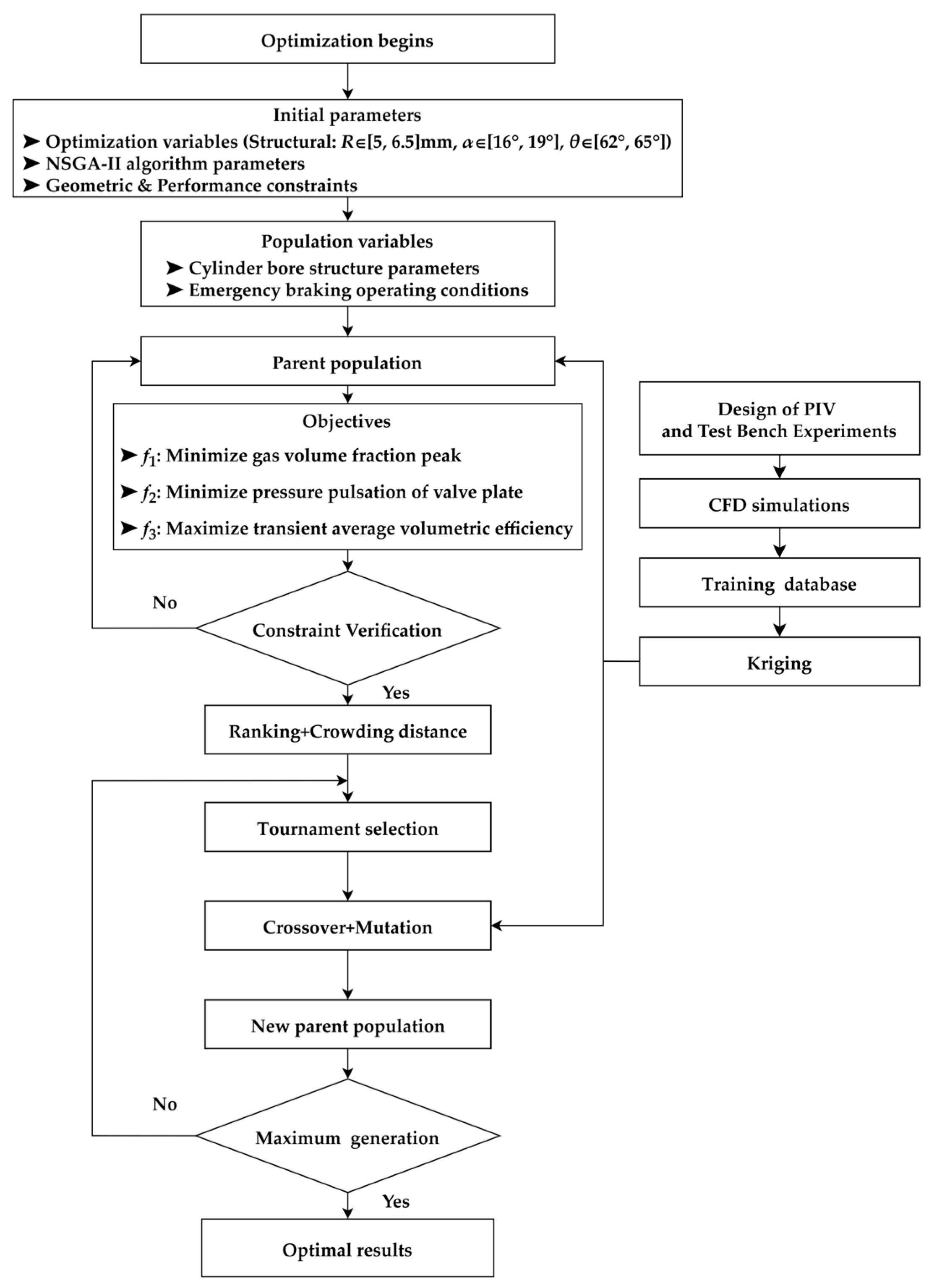
Based on the regulation laws of cylinder bore geometric parameters on cavitation evolution under transient emergency braking conditions revealed in Section 4.1, most existing optimization studies on cavitation suppression in axial piston pumps take time-averaged performance parameters under steady-state rated conditions as the optimization objective [30]. Such methods have been widely verified and applied in conventional steady-state service scenarios. The emergency braking condition of the cotton picker focused on in this paper exhibits strong transient characteristics with drastic fluctuations in pressure, flow rate, and cavitation intensity within a short period. Directly adopting steady-state time-averaged parameters as optimization objectives can hardly match such strong transient characteristics, nor can it fully cover the extreme operating boundaries during the transient process. There exists a potential risk that although time-averaged performance meets design requirements, transient extreme values may exceed limits and cause cavitation and performance failure. Therefore, this section establishes a multi-objective optimization model that balances transient cavitation suppression, volumetric efficiency guarantee, and operational stability improvement, with the extreme eigenvalues within the full operating cycle as the core of optimization. This ensures that the optimized structure can fully cover all extreme operating boundaries during emergency braking. The overall optimization implementation process is shown in Figure 20.
Figure 20.
Optimization flow chart.
Cavitation is the primary cause of performance degradation and structural failure of the piston pump under emergency braking conditions. To accurately characterize the extreme cavitation damage risk over the entire operating cycle, the cycle peak of the volume-averaged gas volume fraction in the cylinder bore region is chosen as the optimization objective. This objective function directly uses the peak gas volume fraction as the indicator of cavitation intensity, instead of a cavitation-number-based criterion. The reason is that the pressure reversal under emergency braking invalidates the steady far-field reference required by the cavitation number. As a direct phase variable, the gas volume fraction better matches the transient physical characteristics of this operating condition. The objective function is expressed as:
where x = [R, α, θ] is the vector of optimization variables, f1(x) is the maximum cavitation intensity in the cylinder bore region over the entire emergency braking cycle, V is the volume of the fluid computational domain in the cylinder bore region in m3, and α (r, t) is the instantaneous local gas volume fraction at time t within the domain. The inner max operator captures the peak cavitation intensity across the whole operating cycle to identify the extreme cavitation moment, and the outer min operator defines the optimization direction.
Severe pressure pulsation under emergency braking is the main cause of increased pump vibration, elevated noise, and wear of the valve plate pair. The objective function is expressed as:
where f2(x) is the maximum pressure pulsation of the pump valve plate over the entire emergency braking cycle, in MPa, and pout(t) is the instantaneous port plate pressure of the pump at time t, in MPa.
To avoid sacrificing hydraulic performance for cavitation suppression, maximizing the transient average volumetric efficiency of the pump under emergency braking is set as a constrained optimization objective. The objective function is expressed as:
where f3(x) is the transient average volumetric efficiency of the pump over the entire emergency braking cycle, dimensionless; T is the total duration of the transient simulation, in seconds; qa is the actual output flow rate of the pump at time t, in m3/s; and qth is the theoretical output flow rate at time t, in m3/s, calculated from the geometric displacement of the pump and the instantaneous spindle speed. This function ensures that the optimized structure maintains stable hydraulic performance throughout the emergency braking process, realizing the collaborative optimization of cavitation suppression and operating performance.
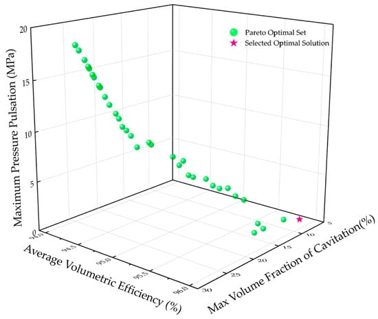
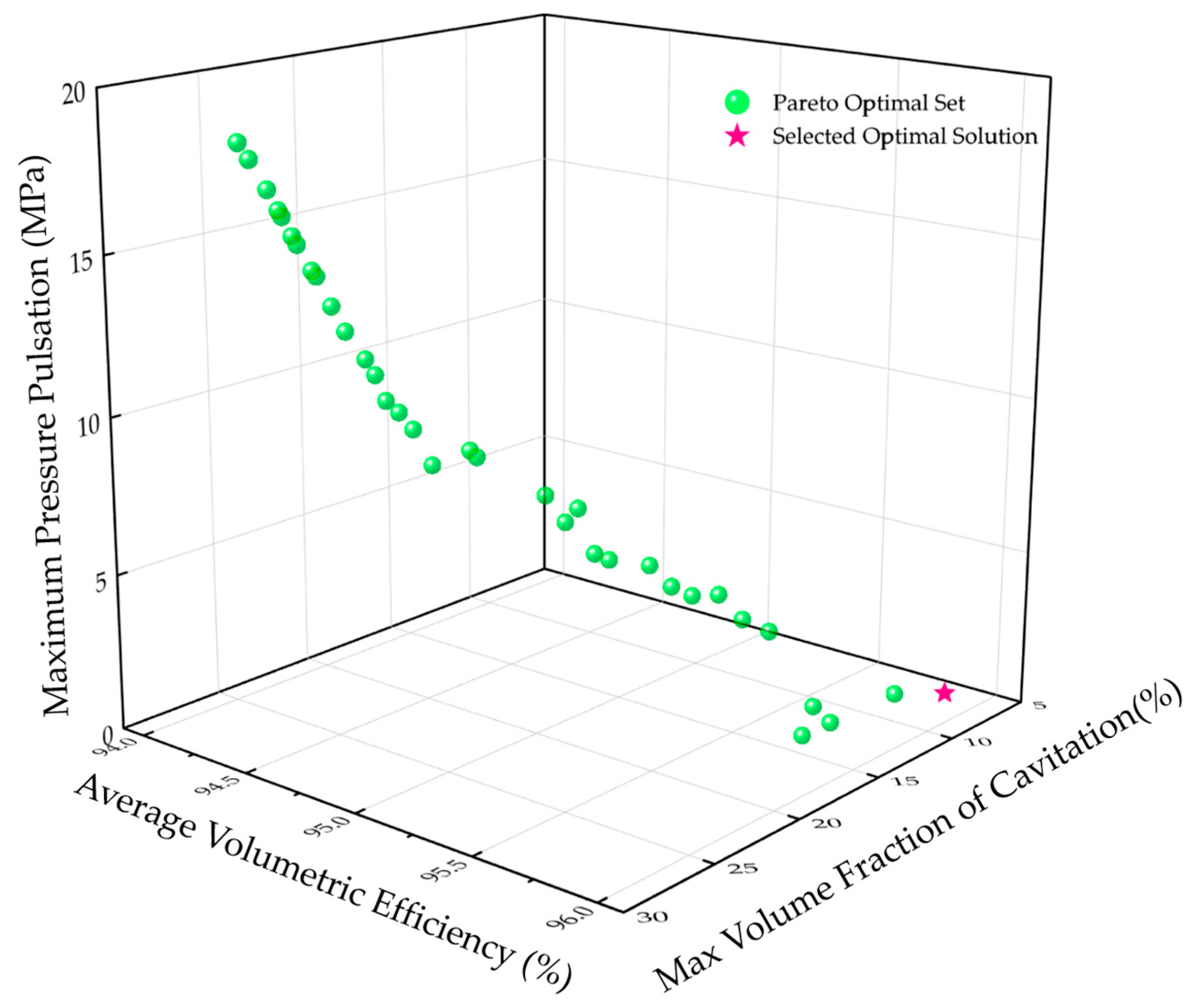
Given the long computation time of a single full-flow-path transient CFD simulation, it is infeasible to directly employ CFD for evaluating all candidate solutions. This paper adopts a two-stage solution strategy combining the Kriging surrogate model with NSGA-II: firstly, the Optimal Latin Hypercube Sampling (OLHS) is used to generate initial sample points within the design space [31]. The Kriging surrogate model is trained based on CFD simulation results, and the model accuracy is verified by Leave-One-Out Cross-Validation (LOOCV) [32] to ensure that the coefficient of determination R2 of the three objective functions all meet the accuracy requirements for engineering optimization. Subsequently, the Kriging model is used instead of CFD to conduct global optimization with NSGA-II. The final Pareto optimal solution set is shown in Figure 21.
Figure 21.
Multi-objective optimization results.
The TOPSIS multi-attribute decision-making method based on the entropy weight method is used to select the final optimization scheme from the Pareto front [33]. The weight distribution is set as w1:w2:w3 = 0.5:0.25:0.25, deliberately treating transient cavitation suppression as the primary objective while balancing volumetric efficiency and pressure pulsation. Because cavitation receives twice the weight of either of the other two objectives, the entropy-weighted TOPSIS distance is dominated by the gas volume fraction axis, and the selected solution is therefore naturally pulled toward the low-cavitation tail of the Pareto front. This explains the apparently low value of the maximum gas volume fraction at the selected optimum: it is not an outlier, but rather the deliberate consequence of the asymmetric weighting that reflects the engineering priority of suppressing local cavitation damage at the cylinder bore and valve plate interface. The finally determined optimal configuration is orifice fillet radius R = 6.49 mm, radial angle α = 18.98°, axial inclination angle θ = 63.74°.
4.3. Effect Verification and Characteristic Analysis of the Optimized Structure
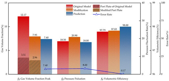
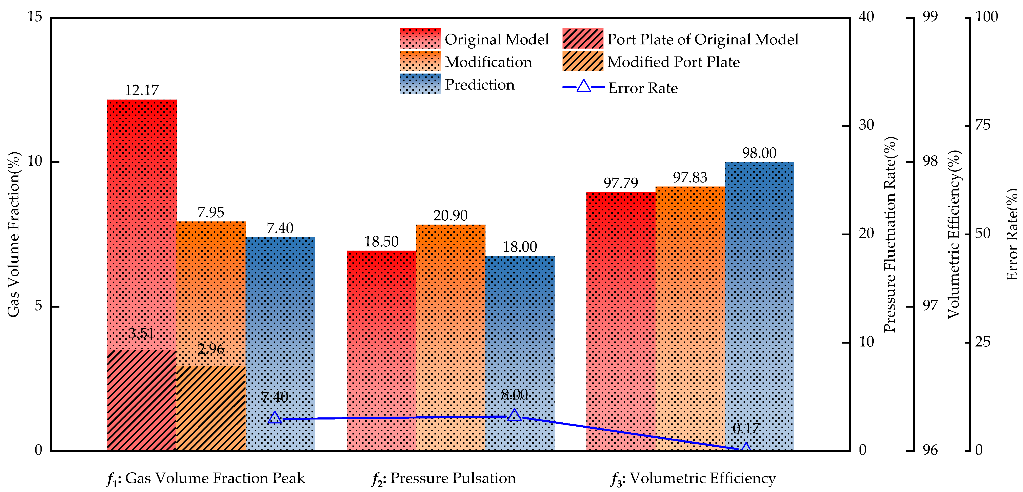
The optimized structure is resubstituted into the full-flow passage transient CFD model for independent verification. Figure 22 compares the core performance under the baseline emergency braking condition on three indicators, namely the gas volume fraction peak, the pressure pulsation, and the volumetric efficiency. For each indicator, three bars are presented to compare the CFD result of the original structure, the CFD result of the optimized structure, and the Kriging surrogate model prediction for the optimized structure. Under f1, two additional hatched bars further isolate the gas volume fraction within the port plate region, which is the most damage-prone local zone. The Error Rate triangle line plotted on the right axis quantifies the relative deviation of the surrogate model prediction from the CFD result.
Figure 22.
Comparison of optimization results.
The comparison results show that the proposed optimized cylinder bore structure achieves significant suppression of transient cavitation under emergency braking conditions:
The cavitation suppression effect is significant. The peak gas volume fraction in the cylinder bore region decreases from 12.17% to 7.95%, with a reduction of 34.7%; the peak gas volume fraction in the valve plate region decreases from 3.51% to 2.96%, with a reduction of 15.7%. After optimization, the cavitation duration is greatly shortened, and there is no obvious stage of intense cavitation development. Only a brief weak cavitation phenomenon occurs at the lowest point of the system pressure. This indicates that the combined optimization of the orifice fillet and axial diverging taper effectively cuts off the cavitation induction chain of throttling–jet–vortex, realizing effective suppression of transient cavitation development.
The volumetric efficiency remains stable. The transient average volumetric efficiency has slightly increased from 97.79% to 97.83%, maintaining the level of the original structure. This indicates that the optimization of the cylinder bore structure does not come at the cost of hydraulic performance, and a good collaborative optimization between cavitation suppression and volumetric efficiency has been achieved.
A slight increase in pressure pulsation was observed. Port plate pressure pulsation increased from 18.50 MPa to 20.90 MPa, with an increase of approximately 12.97%.
Analyzing the reasons, the inlet fillet and axial divergent taper of the cylinder bore have changed the geometric shape of the flow cross-section at the interface between the cylinder bore and the valve plate. Although they effectively suppress the local throttling effect and the formation of wall-attached vortices, thereby reducing the cavitation intensity, they simultaneously alter the transient flow distribution characteristics and pressure wave propagation path in this region. The divergent taper increases the cross-sectional area of the cylinder bore outlet, leading to a corresponding increase in the pressure recovery gradient and the amplitude of flow rate mutation during the transient pressure reversal process, which results in a rise in the peak value of the pump port plate pressure pulsation. The trade-off arises because these two effects act on different flow scales: the geometric smoothing weakens local throttling jets and wall-attached vortices that drive cavitation, while simultaneously stiffening the global pressure-flow response that governs pressure pulsation. The increased pulsation may in turn feed on cavitation through three pathways, namely deeper periodic low-pressure troughs that may reseed dissolved gas liberation, steeper pressure recovery edges that may accelerate bubble collapse, and slight boundary layer destabilization that may locally regenerate small-scale vortices. The CFD verification in Figure 22 confirms that, at the present operating window, the geometric suppression still dominates over these reverse pathways, with the cylinder bore peak gas volume fraction dropping by 34.7% and the valve plate peak by 15.7%, so the optimized scheme remains effective. In the TOPSIS decision-making of this study, the weight of cavitation suppression (w1 = 0.5) is higher than that of pressure pulsation (w3 = 0.25), so the selected scheme prioritizes the cavitation suppression effect and accepts the limited increase in pressure pulsation. For future research, the competitive relationship between the two can be further balanced by introducing the collaborative optimization of damping grooves on the valve plate or increasing the constraint weight of pressure pulsation.
The accuracy of the surrogate model is further evaluated by comparing its predictions with the independent CFD verification results. The relative errors between the predicted values of the three indicators by the Kriging surrogate model and the independent CFD verification values are 7.40%, 8.00% and 0.17%, respectively. Among them, the prediction accuracy of gas volume fraction and volumetric efficiency is satisfactory. The prediction error of pressure pulsation is relatively large, indicating that the ability of the surrogate model to capture pressure pulsation, an indicator more sensitive to detailed flow field characteristics, needs to be improved. This can be addressed in future work by increasing the density of sampling points or adopting higher-order surrogate models. Overall, the prediction trends of the surrogate model are consistent with the CFD verification results, and it meets the basic reliability requirements for engineering optimization.
5. Discussion
This study reveals the dominant role of cavitation in the cylinder bore–valve plate interface region under the strongly transient emergency braking condition, which differs from existing steady-state optimization studies that focus on valve plate relief grooves and piston structures. The dual-vortex structure confirmed by PIV experiments indicates that transient cavitation in this region is dominated by the coupled throttling jet wall vortex mechanism induced by local flow cross-section abrupt changes, rather than global low-pressure driving. This finding explains why cavitation persists even after system pressure recovers, and also verifies the failure of conventional cavitation number criteria under pressure reversal conditions, supporting the rationality of using gas volume fraction as the evaluation index for transient cavitation.
The combined optimization of the orifice fillet and diverging taper reduces the peak gas volume fraction in the total flow domain by 34.7% and the peak gas volume fraction in the valve plate region by 15.7%, while maintaining the volumetric efficiency above 97.8%, achieving a significant cavitation suppression effect. Meanwhile, the port plate pressure pulsation increases by 12.97%, reflecting the competitive trade-off between cavitation suppression and pressure pulsation control. This stems from the difference in their flow field driving scales: cavitation is dominated by local vortices, whereas pressure pulsation is governed by global flow distribution. In this study, a technically acceptable compromise solution was achieved through differentiated TOPSIS weights. Furthermore, adopting the full-cycle extreme peak value rather than the time-averaged value as the objective function effectively avoids the potential failure risk where the time-averaged performance meets the requirements but the transient extreme value exceeds the limit.
The limitations of this study are as follows: The transient emergency braking condition cannot be fully reproduced on the test bench, and model verification relies on two indirect methods: steady-state experiments and PIV measurements; the optimized scheme has not yet been verified by the whole-machine test of the cotton picker; the prediction error of the Kriging model for pressure pulsation is higher than that for other indicators. Future work will promote the collaborative optimization of the cylinder bore and valve plate damping grooves to balance pressure pulsation.
6. Conclusions
This study investigates the transient cavitation mechanism and structural optimization of the cylinder bore–valve plate interface region of the 180 mL/r closed-type axial piston pump for the cotton picker under emergency braking conditions. The main conclusions are as follows:
- (1)
- Using a full-flow-path transient CFD model and PIV visualization tests, the cylinder bore–valve plate interface is identified as the key cavitation zone. The coupled cavitation mechanism is proposed and verified, which involves abrupt flow cross-section variation, throttling jet, attached vortex formation, local low-pressure generation, and gas liberation.
- (2)
- Systematic three-parameter and full-factor transient CFD simulations quantify the staged regulatory effects: radial radius dominates cavitation incipience, radial angle governs the full-cycle cavitation evolution, and axial inclination angle controls the continuous development of cavitation.
- (3)
- A multi-objective optimization model is constructed based on full-cycle extreme characteristic values. The optimal configuration is obtained via Kriging-assisted NSGA-II algorithm combined with entropy-weight TOPSIS decision-making. The peak gas volume fraction in the whole flow domain is decreased by 34.7%, the volumetric efficiency remains above 97.8%, and the pressure pulsation rises by 12.97%, revealing the competitive trade-off between multiple objectives.
- (4)
- Targeted optimization of the cylinder bore requires no modification to the overall structure of the valve plate or cylinder block, offering an engineering-practical new strategy for transient cavitation suppression in closed-circuit piston pumps.
Author Contributions
Methodology, Y.W.; software, Y.W. and X.W.; validation, Y.W. and Y.Z.; formal analysis, Y.W.; investigation, Y.L. and X.K.; resources, Y.Z. and M.W.; data curation, Y.Z. and M.W.; writing—original draft preparation, Y.W.; writing—review and editing, J.Z.; visualization, X.W.; supervision, J.Z.; funding acquisition, J.Z. All authors have read and agreed to the published version of the manuscript.
Funding
This work was funded by the National Key Research and Development Program of China (No.2023YFB3406701).
Data Availability Statement
Data will be made available on request.
Conflicts of Interest
Author Xu Wang was employed by the company Yantai Eddie Hydraulic Technology Co., Ltd. The remaining authors declare that the research was conducted in the absence of any commercial or financial relationships that could be construed as a potential conflict of interest.
References
- Shi, Y.; Lin, T.; Meng, G.; Huang, J. A Study on the Suppression of Cavitation Flow Inside An Axial Piston Pump. In Proceedings of the 2016 Prognostics and System Health Management Conference (PHM-Chengdu), Chengdu, China, 19–21 October 2016; pp. 1–5. [Google Scholar]
- Chao, Q.; Xu, Z.; Tao, J.F.; Liu, C.L. Capped piston: A Promising Design to Reduce Compressibility effects, Pressure Ripple and Cavitation for High-speed and High-pressure Axial Piston Pumps. Alex. Eng. J. 2024, 62, 509–521. [Google Scholar] [CrossRef] [Scilit]
- Suo, X.; Jiang, Y.; Wang, W. Hydraulic Axial Piston Pump: Gaseous and Vaporous Cavitation Characteristics and Optimization method. Eng. Appl. Comput. Fluid Mech. 2021, 15, 712–726. [Google Scholar]
- Yan, S.; Jiang, Y.; Hu, M.Y. Study on the Cavitation Suppression Mechanism of Axial Piston Pump. Int. J. Aerosp. Eng. 2022, 2022, 9913739. [Google Scholar] [CrossRef] [Scilit]
- Ye, S.G.; Zeng, C.; Tang, H.S.; Bao, Y.; Wang, J.L.; Zhao, S.D.; Ren, Y. Research on Cavitation Characteristics of Axial Piston Pump Based on Computational Fluid Dynamics Model. Phys. Fluids 2025, 37, 075131. [Google Scholar] [CrossRef] [Scilit]
- Wu, T.; Zhang, J.X.; Li, R.C.; Yuan, W.T.; Sun, Q.Y.; Chen, S.; Li, D.R.; Sun, Y.H. Analysis and Optimization of Flow Field Characteristics of Axial Piston Motor Based on CFD. Flow Meas. Instrum. 2024, 99, 102669. [Google Scholar] [CrossRef] [Scilit]
- Huang, W.D.; Li, X.G.; Wan, H.B.; Lv, Y.P.; Cai, J.D.; Yang, Y.B. Conical Cylinder Clock: A Key Solution to Alleviate Cavitation in the Piston Chamber of Axial Piston Pumps. Phys. Fluids 2025, 37, 086140. [Google Scholar] [CrossRef]
- Pan, Y.; Zhang, D.; Wang, Z.N.; Zou, X.; Yuan, H. Flow Pulsation Characteristics of Variable Displacement Piston Pump Considering Coupling Effects Cavitation Bubble and Swash Plate Inclination Angle Vibration. Phys. Fluids 2024, 36, 056130. [Google Scholar] [CrossRef] [Scilit]
- Zhang, B.; Zhao, C.X.; Hong, H.C.; Cheng, G.Z.; Yang, H.Y.; Feng, S.B.; Zhai, J.; Xiao, W.H. Optimization of the Outlet Unloading Structure to Prevent Gaseous Cavitation in a High-Pressure Axial Piston Pump. Proc. Inst. Mech. Eng. Part C J. Mech. Eng. Sci. 2022, 236, 3459–3473. [Google Scholar] [CrossRef] [Scilit]
- Ge, T.; Hu, L.; Su, R.; Ruan, X. Analysis of cavitation and shear in bellows pump: Transient CFD modelling and high-speed visualization. Eng. Appl. Comput. Fluid Mech. 2023, 17, 2247474. [Google Scholar] [CrossRef] [Scilit]
- Al-Obaidi, A.R. Evaluation and Investigation of Hydraulic Performance Characteristics in an Axial Pump Based on CFD and Acoustic Analysis. Processes 2024, 12, 129. [Google Scholar] [CrossRef] [Scilit]
- Pasunuthi, S.S.; Corvaglia, A.; Rigosi, M.; Dhar, S.; Manne, V.H.; Ding, H.; Monterosso, F. Computational Fluid Dynamics Based Cavitation Erosion Prediction in A Swash Plate Piston Pump. In Proceedings of the ASME 2025 Fluids Engineering Division Summer Meeting, Philadelphia, PA, USA, 27–30 July 2025; p. V002T08A015. [Google Scholar]
- Zhao, B.; Guo, W.; Quan, L. Cavitation of a Submerged Jet at the Spherical Valve Plate/cylinder Block Interface For Axial Piston Pump. Chin. J. Mech. Eng. 2020, 33, 67. [Google Scholar] [CrossRef] [Scilit]
- Voskresensky, G.G. On Cavitation in the Hydraulic Drives of Mobile Machines. Earth Environ. Sci. 2021, 666, 052068. [Google Scholar] [CrossRef] [Scilit]
- Mo, L.; Yang, Q.; Yang, Y.; Zeng, Z. Failure Analysis of Cavitation in A Hydraulic Loader. Eng. Fail. Anal. 2016, 66, 312–320. [Google Scholar] [CrossRef] [Scilit]
- Manhartsgruber, B.; Scheidl, R. Cavitation Driven Impact in a Hydraulic Piston Pump: A Theoretical and Experimental Investigation. In Proceedings of the ASME 1997 Design Engineering Technical Conferences and Computers and Information in Engineering Conference, Online, 17–19 August 2021; p. V01DT19A001. [Google Scholar]
- Yang, L.; Yin, S.; Niu, Q. Cavitation Characteristics of Hydraulic Axial Piston Motor Based on CFD Technology. World J. Eng. 2017, 14, 231–236. [Google Scholar] [CrossRef] [Scilit]
- Yang, K.H.; Liu, C.B.; Wu, Q.T.; Li, X.S. Multi-objective Optimization Design for a Hydrodynamic Retarder Based on CFD Simulation Considering Cavitation Effect. Proc. Inst. Mech. Eng. Part D. J. Automob. Eng. 2021, 236, 647–660. [Google Scholar] [CrossRef] [Scilit]
- Huang, R.; Luo, X.; Ji, B.; Wang, P.; Yu, A.; Zhai, Z.; Zhou, J. Multi-Objective Optimization of a Mixed-Flow Pump Impeller Using Modified NSGA-II Algorithm. Sci. China Technol. Sci. 2015, 58, 2122–2130. [Google Scholar] [CrossRef] [Scilit]
- Ren, Y.; Mo, X.F.; Zhao, L.Z.; Zheng, S.H.; Yang, Y.D. Multi-Objective Optimization of Two-Vane Pump Based on NSGA-III Algorithm. J. Fluid Mach. Syst. 2024, 17, 132–142. [Google Scholar] [CrossRef] [Scilit]
- Gül, K.; Dönmez, A.H.; Temsah, A.; Farhat, M. Enhancing Pump Performance Via Multi-Objective Optimization Using CFD and NSGA-II Algorithm. Eng. Comput. 2026, ahead-of-print. [Google Scholar] [CrossRef] [Scilit]
- Zhang, J.Y.; Zhu, H.W.; Yang, C.; Li, Y.; Wei, H. Multi-Objective Shape Optimization of Helico-Axial Multiphase Pump Impeller Based on NSGA-II and ANN. Energy Convers. Manag. 2011, 52, 538–546. [Google Scholar] [CrossRef] [Scilit]
- Sun, Z.; Zhu, Y.; Chen, J.; Wang, M.; Tang, F.; Lyu, N.; Chen, S. Multi-Objective Optimization of S-Shaped Hydrofoil and Bidirectional Axial-Flow Pumps Based on NSGA-II. Trans. Chin. Soc. Agric. Eng. 2024, 40, 39–48. [Google Scholar]
- Apte, D.; Razaaly, N.; Fang, Y.; Ge, M.; Sandberg, R.; Coutier-Delgosha, O. A Novel Data-Driven Method for Augmenting Turbulence Modeling for Unsteady Cavitating Flows. Int. J. Heat. Fluid Flow 2025, 115, 109847. [Google Scholar] [CrossRef] [Scilit]
- Singhal, A.K.; Athavale, M.M.; Li, H.; Jiang, Y. Mathematical Basis and Validation of the Full Cavitation Model. ASME. J. Fluids Eng. 2002, 124, 617–624. [Google Scholar] [CrossRef] [Scilit]
- Zwart, P.J.; Gerber, A.G.; Belamri, T. A Two-Phase Flow Model for Predicting Cavitation Dynamics. In Proceedings of the 5th International Conference on Multiphase Flow (ICMF 2004), Yokohama, Japan, 30 May–4 June 2004. Paper No. 152. [Google Scholar]
- Kunz, R.F.; Boger, D.A.; Stinebring, D.R.; Chyczewski, T.S.; Lindau, J.W.; Gibeling, H.J.; Venkateswaran, S.; Govindan, T.R. A Preconditioned Navier–Stokes Method for Two-Phase Flows with Application to Cavitation Prediction. Comput. Fluids 2000, 29, 849–875. [Google Scholar] [CrossRef] [Scilit]
- Iannetti, A.; Stickland, M.T.; Dempster, W.M. A CFD and Experimental Study on Cavitation in Positive Displacement Pumps: Benefits and Drawbacks of the ‘Full’ Cavitation Model. Eng. Appl. Comput. Fluid Mech. 2016, 10, 7–71. [Google Scholar] [CrossRef] [Scilit]
- Schwarz, M.P.; Turner, W.J. Applicability of the Standard k-ε Turbulence Model to Gas-Stirred Baths. Appl. Math. Model. 1998, 12, 377–386. [Google Scholar] [CrossRef] [Scilit]
- Dugue, C.; Fruman, D.H.; Billard, J.; Cerrutti, P. Dynamic Criterion for Cavitation of Bubbles. ASME. J. Fluids Eng. 1992, 114, 250–254. [Google Scholar] [CrossRef] [Scilit]
- Rajabi, M.M.; Ataie-Ashtiani, B.; Janssen, H. Efficiency Enhancement of Optimized Latin Hypercube Sampling Strategies: Application to Monte Carlo Uncertainty Analysis and Meta-modeling. Adv. Water Resour. 2015, 76, 127–139. [Google Scholar] [CrossRef] [Scilit]
- Tang, J.; Chen, Y.; Liu, B.; Cao, J.; Wang, J. Adaptive Lag Binning and Physics-Weighted Variograms: A LOOCV-Optimised Universal Kriging Framework with Trend Decomposition for High-Fidelity 3D Cryogenic Temperature Field Reconstruction. Processes 2025, 13, 3160. [Google Scholar] [CrossRef] [Scilit]
- Krohling, R.A.; Pacheco, A.G.C. A-TOPSIS—An approach Based on TOPSIS for Ranking Evolutionary Algorithms. Procedia Comput. Sci. 2015, 55, 308–317. [Google Scholar] [CrossRef] [Scilit]

Disclaimer/Publisher’s Note: The statements, opinions and data contained in all publications are solely those of the individual author(s) and contributor(s) and not of MDPI and/or the editor(s). MDPI and/or the editor(s) disclaim responsibility for any injury to people or property resulting from any ideas, methods, instructions or products referred to in the content. |
© 2026 by the authors. Licensee MDPI, Basel, Switzerland. This article is an open access article distributed under the terms and conditions of the Creative Commons Attribution (CC BY) license.