


Abstract
This study achieves a 30.8% mass reduction in amphibious UAV rotary arms via additive manufacturing-constrained topology optimization (AM-constrained TO), establishing lightweight design as the primary objective. To evaluate structural efficiency, we systematically compare three strategies: AM-constrained TO, Hexagonal Honeycomb infill (HC), and central lightening holes (ES). All configurations target comparable mass reduction. Using the SIMP method with manufacturing constraints, TO designs were generated. FEA and tensile tests evaluated stiffness, strength, failure modes, and Specific Energy Absorption (SEA). The key innovation lies in the TO approach: It achieves the primary objective of 30.8% mass reduction while simultaneously enhancing structural integrity and outperforming HC, ES, and Solid Baseline (SB) configurations in stiffness (2234 ± 76 MPa), Specific Energy Absorption (742 ± 29 J/m3), and stress distribution uniformity. The HC configuration shows progressive collapse but has the lowest stiffness (886 ± 17 MPa) and SEA (432 ± 5 J/m3) due to FDM inter-layer bonding limits. The ES configuration has the second-highest tensile strength (19.489 ± 0.19 MPa), but stress concentration around the hole reduces energy absorption, resulting in lower SEA (620 ± 15 J/m3) than TO.
1. Introduction
Multi-rotor UAVs are critical for emergency rescue, material delivery, and infrastructure monitoring due to high maneuverability, rapid deployment, and environmental adaptability [1,2,3,4]. However, expanding applications reveal key challenges: system performance bottlenecks, limited environmental adaptability, and constrained mission effectiveness [3,5].
To overcome these bottlenecks and enhance UAV operational capabilities in complex environments, researchers have developed reconfigurable multi-rotor UAVs. By dynamically adjusting their structural configurations, these UAVs achieve efficient adaptation across multiple mission scenarios such as navigating confined spaces and grasping targets [6,7]. Representative examples include Wu et al. and Xu et al., who designed grasping-capable annular rotors and eagle-claw-inspired deformable quadrotors, respectively, significantly enhancing operational capabilities in constrained spaces [8,9]. Technologically, reconfigurable structures are primarily categorized into three types: tiltrotor, multi-modal hybrid, and foldable designs [6]. Specifically, tilt-rotor systems enable omnidirectional propulsion through rotor reorientation [9]; multi-modal hybrids, exemplified by the wheel-wing robot of Mintchev et al., achieve mode switching between terrestrial locomotion and flight [10]; while foldable designs, such as the scissor-mechanism UAV of Falanga et al., can alter airframe dimensions during flight to traverse narrow openings [11]. These designs share the common objective of expanding UAV mission envelopes through structural reconfiguration while maintaining a favorable power-to-weight ratio [5,12]. Beyond macroscopic structural reconfiguration, bio-inspired active morphing at the component level, such as the coupled spanwise folding and chordwise twisting of ornithopter wings, has also been demonstrated to significantly enhance attitude control agility and flight maneuverability [13]. This underscores the broader principle that adapting morphology—whether at the system or component level—is key to unlocking advanced UAV capabilities.
As a critical branch of reconfigurable UAVs, land–air amphibious systems integrate aerial and terrestrial mobility, effectively extending endurance, enhancing adaptability to complex terrains, and demonstrating unique advantages in disaster response scenarios [14]. Representative advances include Fan et al.’s two-wheeled hybrid platform that reduces energy consumption by up to 80% in ground mobility mode compared to pure flight [14], Kalantari et al.’s “Drivocopter”, which enables air-ground locomotion via four spherical wheels [15], and the FCSTAR robot of Ben David and Zarrouk, capable of multimodal operation including flying, running, and climbing [16]. However, the practical deployment of land–air amphibious UAVs still faces core challenges in structural lightweight design and multifunctional integration.
Lightweight design is fundamental to enhancing the overall performance of amphibious UAVs. Numerous biological structures in nature provide critical inspiration for lightweight design [17]. For instance, the efficient material distribution mechanisms in avian skeletons and the exceptional specific strength/stiffness exhibited by beetle elytra microstructures serve as archetypes for biomimetic design [18]. Furthermore, metamaterials developed by Ghoddousi et al. based on Fibonacci spirals demonstrate tunable energy absorption characteristics [19], highlighting the potential of bio-inspired structures in lightweighting and mechanical performance. However, conventional biomimetic designs are often constrained by specific loading conditions, posing challenges for the global optimization of stiffness, strength, and energy absorption efficiency [20].
Topology optimization offers an effective approach to address this challenge. This methodology enables the concurrent design of lightweight structures with optimized multiple performance metrics by optimizing material distribution while satisfying load and constraint conditions [18,21,22]. For instance, Zhu et al. implemented topology optimization in A380 leading-edge rib design, achieving significant weight reduction while fulfilling all performance requirements [23]. When integrated with additive manufacturing, topology optimization enables the fabrication of high-performance lightweight components, as exemplified by the aerospace bracket developed at Northwestern Polytechnical University [24] and its successful application in enhancing the fatigue life of heavy-duty robotic joints [25].
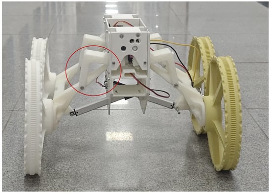
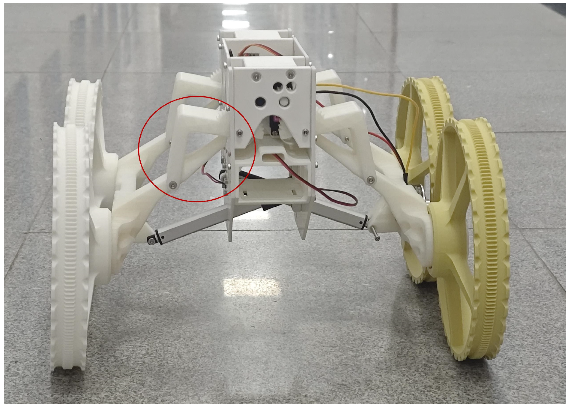
This study introduces a pioneering lightweight design strategy for amphibious UAV rotary arms—critical load-bearing components (as shown in Figure 1)—using additive manufacturing (AM)-constrained topology optimization (TO). To demonstrate its efficacy, four configurations were systematically evaluated: a TO design incorporating explicit Fused Deposition Modeling (FDM) constraints, a Hexagonal honeycomb-filled (HC) structure, a central lightening hole (ES) design, and a Solid Baseline (SB). The primary contribution of this research lies in establishing AM-constrained TO as a transformative paradigm for UAV structural design. Unlike conventional lightweighting strategies (e.g., HC and ES) that inherently sacrifice mechanical performance, this novel approach uniquely realizes a 30.8% mass reduction while concurrently achieving significant enhancements in mechanical properties.
Figure 1.
Physical prototype of land–air amphibious UAV.
Mechanistically, the TO design achieves these dual benefits by fundamentally reconfiguring the internal load paths. Governed by manufacturing constraints, the optimization algorithm precisely redistributes material along principal stress trajectories to construct a near-ideal load-bearing skeleton. This intrinsic structural efficiency translates quantitatively into superior stiffness. Furthermore, it sustains load-bearing capacity post-yielding across a broader deformation volume, directly resulting in a Specific Energy Absorption (SEA) that is 72% and 20% higher than those of the HC and ES configurations, respectively.
Consequently, the central objective of this study is to rigorously validate this innovative AM-constrained TO methodology. By quantifying its capacity to meet aggressive lightweight targets while substantially outperforming conventional empirical designs (HC and ES) in critical mechanical metrics—such as stiffness, strength, and energy absorption—under representative tensile loading, this research demonstrates the method’s effectiveness in overcoming traditional lightweighting trade-offs.
2. Materials and Methods
The core of this study involves comparing three distinct lightweight design strategies applied to the UAV rotary arm. This subsection elaborates on the specific methodologies used to generate each configuration: (1) Topology Optimization (TO)-incorporating AM constraints, (2) Hexagonal Honeycomb Infill (HC), and (3) the central lightening hole (ES) approach. The Solid Baseline (SB) model serves as the reference for comparison.
2.1. Lightweight Configurations Design Methodology
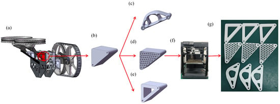
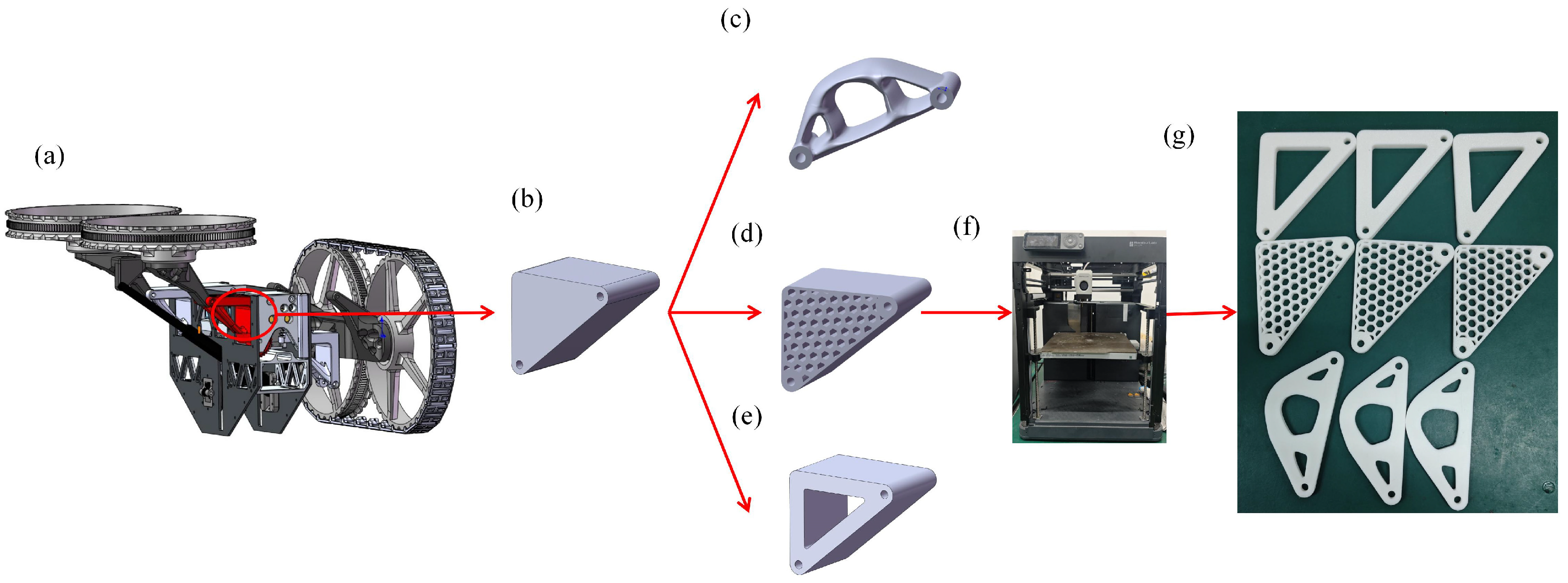
This study conducts optimization design on rotary arms from a reference open-source land–air UAV design, as illustrated in Figure 2a. To simplify the model, non-critical features (gears and fillets) were omitted, retaining only essential external contours and mounting hole structures. The baseline model was reconstructed using SolidWorks 2023 software, shown in Figure 2b. Based on this, three lightweight configurations were parametrically designed within the baseline model’s configuration space: Topology Optimization (TO) configuration, Hexagonal Honeycomb Infill (HC) configuration, and central lightening hole (ES) configuration, depicted in Figure 2c–e respectively. All optimized configurations maintained comparable volumes to ensure a fair comparison.
Figure 2.
(a) Original open-source UAV rotary arm; (b) simplified baseline model; (c) topology-optimized (TO) configuration; (d) Hexagonal honeycomb-filled (HC) configuration; (e) central lightening hole (ES) configuration; (f) schematic of FDM-printed specimen; (g) schematic of FDM-printed specimen.
2.1.1. Topology-Optimized Structural Design Methodology
The core objective of the topology optimization was the breakthrough lightweight design of the amphibious UAV rotary arm, specifically targeting mass reduction while enhancing structural performance. To achieve this, we employed topology optimization based on the Solid Isotropic Material with Penalization (SIMP) method. Critically, as the key methodological innovation, this optimization explicitly integrated manufacturing constraints inherent to the Fused Deposition Modeling (FDM) process into the formulation. These constraints were not merely post-processing considerations but fundamental drivers of the optimized material distribution, ensuring both manufacturability and performance under operational loads. The efficacy of this integrated AM-constrained TO approach in simultaneously achieving the aggressive mass target and superior mechanical properties was then rigorously validated against two conventional lightweight design strategies—Hexagonal Honeycomb Infill (HC) and central lightening hole (ES) configurations—all designed for comparable volume reduction.
The topology optimization was implemented in Altair Inspire 2024.1.1 software. The core methodology describes material distribution within the design domain using continuous pseudo-density (). Intermediate density values are penalized through an exponent penalty factor P, driving the optimization toward clear “solid material ()” or “void ()” configurations. The macroscopic elastic modulus relates to relative density through the following nonlinear interpolation function:
where denotes the elastic modulus of solid polylactic acid (PLA) material (set as 3000 MPa), represents a minimum value threshold for numerical stability, and is the penalty factor.
The optimization explicitly targets 30.8% mass reduction: Minimize compliance subject to a 40% mass fraction constraint—the mathematical embodiment of the lightweighting goal. This constraint directly enforces the primary objective of 30.8% mass reduction. Additional critical constraints include FDM extrusion constraints along the Z-axis build direction to prevent unsupported overhangs, and non-design domains (frozen regions) for mounting pillars.
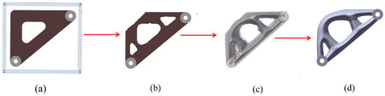
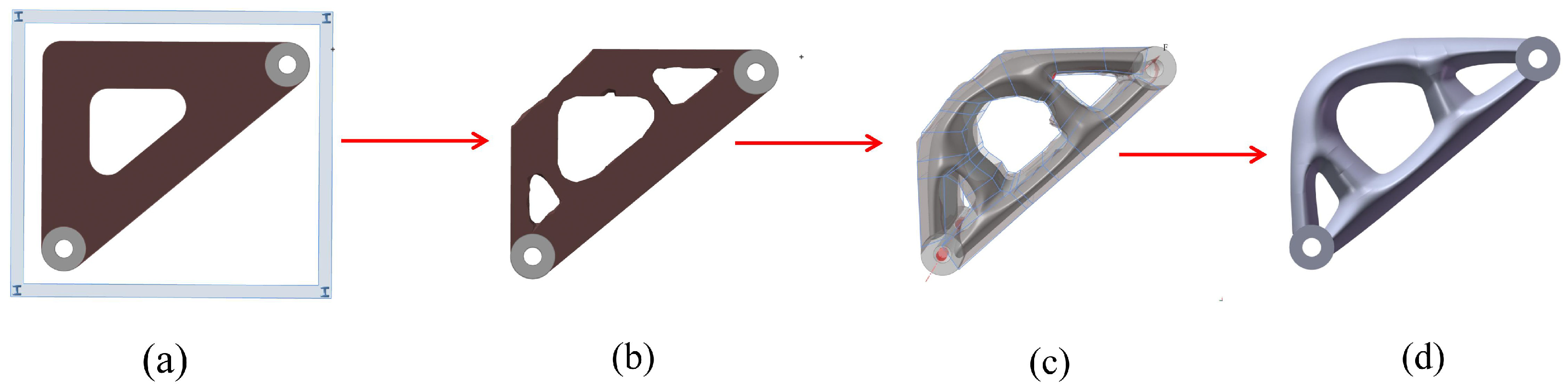
The model designates the rotary arm’s central body as the design domain while freezing the mounting pillars. To comply with the requirements of the Fused Deposition Modeling (FDM) process (printing orientation along the Z-axis), an extrusion constraint is applied along the Z-axis to eliminate unfabricable overhang structures, with the specific constraint configuration illustrated in Figure 3a. Boundary conditions enforce a fully fixed constraint on one bolt hole’s inner surface and a 500 N tensile load on the opposing hole’s inner surface. The optimization implements the 40% mass fraction constraint for lightweighting, shown in Figure 3b.
Figure 3.
Topology optimization process: (a) model setup; (b) optimization; (c) reconstruction; (d) final design.
The optimized topology is reconstructed into geometry using PolyNURBS technology, as depicted in Figure 3c. The carefully reconstructed PolyNURBS geometry was selected as the final design solution after evaluation, owing to its high geometric fidelity, superior surface smoothness, and complete preservation of critical structural features. Transition fillets (1–3 mm) are incorporated at key locations of the final model to mitigate stress concentrations. The finalized design complies with FDM manufacturability rules and satisfies all optimization constraints, serving as the topology-optimized configuration (TO configuration) for subsequent comparative analyses, shown in Figure 3d.
2.1.2. Honeycomb Infill Configuration Design
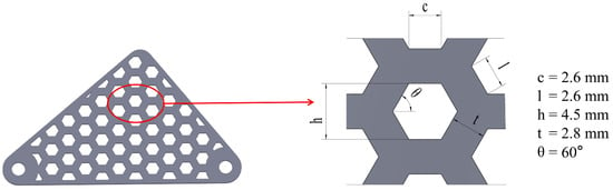
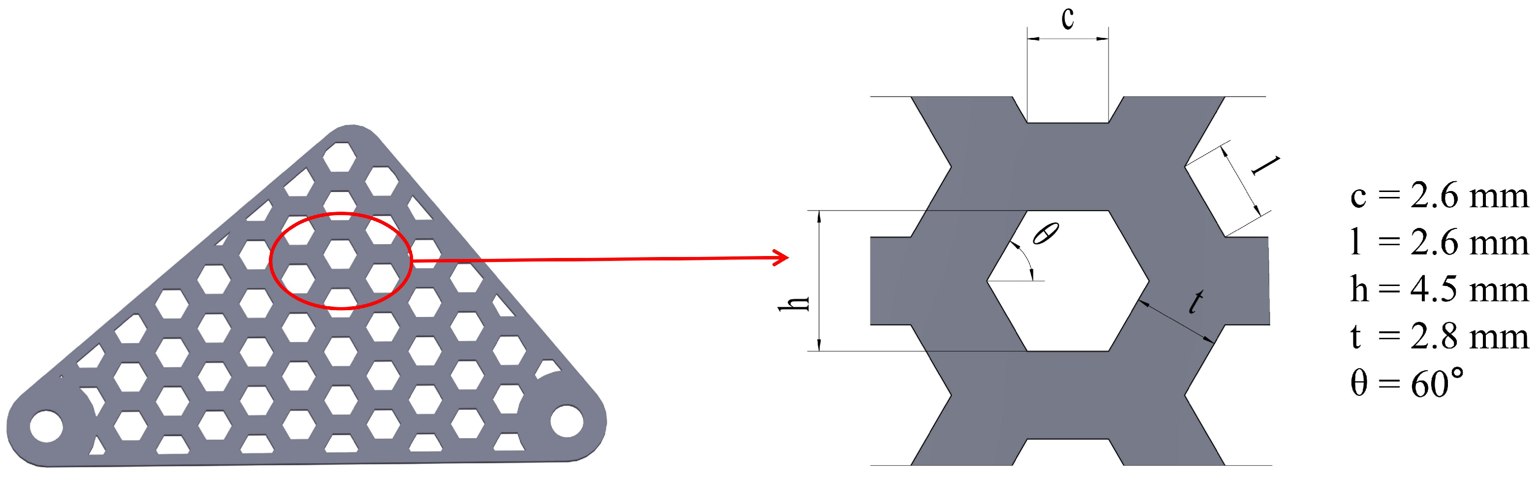
Based on cellular structure principles, the Hexagonal Honeycomb Infill (HC) configuration employs a regular Hexagonal Honeycomb infill strategy. Geometric features of the cellular units are parametrically controlled while preserving the outer contour and critical fillet features of the baseline model. Material in the primary region is systematically substituted to achieve a structured redistribution. A parametrically driven model is constructed using SolidWorks 2023, with the following core variables defined: unit cell lattice constant: (opposite-side distance of the hexagon); cell wall thickness: ; infill region ratio: 79.25% of the main component volume (this ratio is determined through volumetric equivalence calculation to ensure mass consistency with the topology-optimized configuration), as illustrated in Figure 4. The relative density of the honeycomb structure is explicitly defined by geometric parameters:
Figure 4.
Schematic diagram of parametric design for Hexagonal Honeycomb filling configuration.
The final component mass is maintained essentially consistent with that of the topology-optimized configuration, ensuring comparative fairness. The honeycomb array is aligned with the primary load-bearing axis of the component to match the layer-wise deposition characteristics of FDM. A 2 mm preserved boundary of the original part contour is retained at external edges, with all cellular voids designed as through-holes to eliminate enclosed cavities that may cause support residue. Through this systematic topological substitution with regular honeycombs, a theoretical material reduction of 30–40% is achievable while guaranteeing critical stiffness thresholds, significantly enhancing lightweighting efficiency. This strategy provides a quantifiable parametric upgrade path for conventional empirical design approaches.
2.1.3. Central Lightening Hole Configuration Design
In lightweight design research, to establish a comparative benchmark for empirical methods, this study proposes and implements a central lightening hole configuration based on scaling law (denoted as ES configuration). The scheme was implemented in SolidWorks 2023 using a simplified swing-arm reference model with a triangular primary profile as the geometric basis. The design core involves: (1) selecting the centroid of the main triangular profile as a reference point, (2) applying uniform scaling with a scaling factor . This factor was calculated to ensure volumetric equivalence with the topology-optimized configuration, (3) generating a scaled-down similar triangular inner profile, and (4) executing through-thickness extrusion cutting to create lightweight cavities in the central load-bearing region. This process strictly preserves critical functional features, including mounting pillars and holes on both sides. The resultant triangular cavity occupies 29.16% of the original profile area, with dimensions calibrated to maintain a total volume equivalent to those of the TO and HC configurations, ensuring fairness in performance evaluation. The approach offers significant advantages in design efficiency and intuitiveness, relying solely on engineering heuristics.
2.2. Specimen Fabrication and Preparation
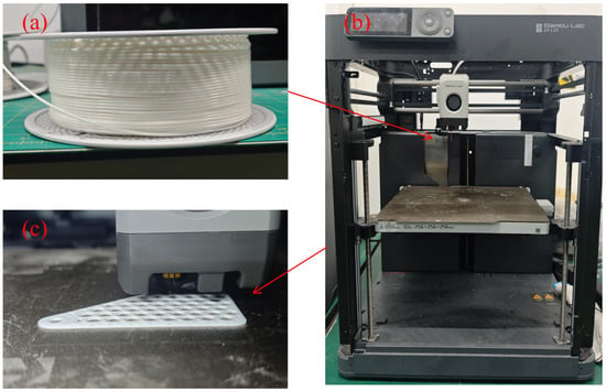
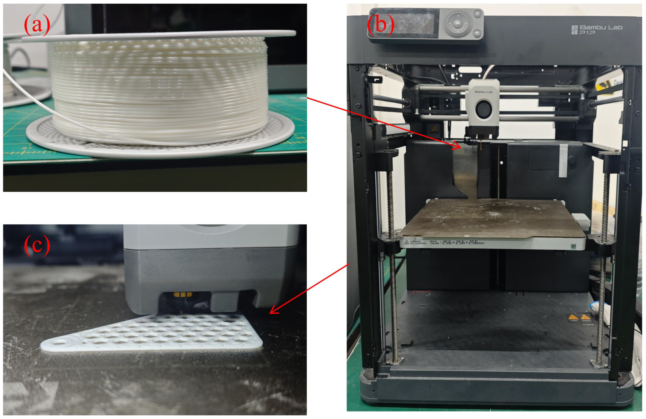
This study employed Bambu PLA Basic polylactic acid (PLA) (Shenzhen Bambu Technology Co., Ltd., Shenzhen, China) with a melting point of 220 °C as the 3D printing material. A Bambu P2S 3D printer (Shenzhen Bambu Technology Co., Ltd., Shenzhen, China) with a single-nozzle extrusion system (nozzle diameter: 0.4 mm) processed PLA filaments with 1.75 mm diameter and 1.25 g/cm3 density, as illustrated in Figure 5a,b. Specimens of three optimized designs—topology-optimized, Hexagonal Honeycomb, and central lightening hole (ES) configurations—were modeled in SolidWorks and manufactured using Bambu Studio 2.4.0.70 slicing software (Figure 2g). Tree supports were applied to topology-optimized structures while full overhang supports were used for others, followed by 8 h post-printing drying at 25 °C. An integrated methodology combining tensile testing and finite element simulation was employed to systematically compare mechanical responses under tensile loading, with emphasis on the trade-offs between mass and load-bearing capacity. Material properties and process parameters are detailed in Table 1 and Table 2.
Figure 5.
(a) PLA consumables; (b) 3D printer; (c) printing process.
Table 1.
3D printing material.
Table 2.
3D printer parameters.
2.3. Finite Element Analysis
Finite element analysis (FEA) was conducted using Abaqus/Standard 2022 commercial software. The FEA workflow began with importing the STEP file from SolidWorks into Abaqus, followed by material property assignment, where PLA was modeled with density , elastic modulus E = 3000 MPa, and Poisson’s ratio . Based on the principle of equivalent static load, complex flight loads were simplified to a critical static condition: a 500 N tensile load was applied along the axis connecting mounting holes, with the inner surface of one hole fixed (simulating airframe connection) and tensile force imposed on the opposite hole (representing operational load). A mesh convergence study was conducted with four levels of refinement (element sizes: 3.0 mm, 2.0 mm, 1.5 mm, and finally 0.75 mm). When refining from 1.5 mm to 0.75 mm, the maximum displacement variation was below 5%, meeting engineering accuracy criteria and confirming mesh independence at 0.75 mm element size.
2.4. Tensile Test
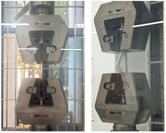
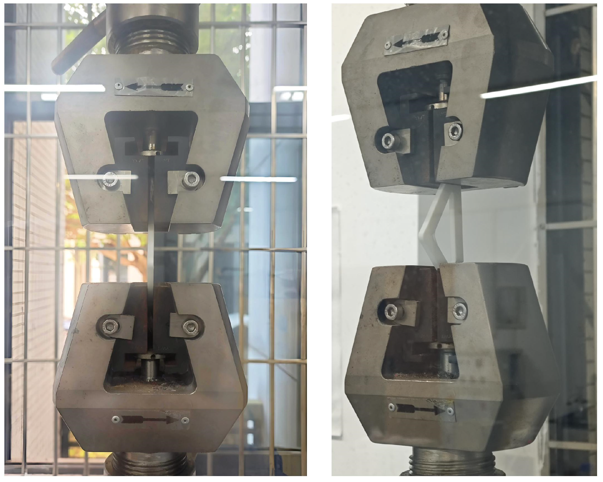
Mechanical testing was conducted to directly validate simulation results and quantify structural performance through quasi-static tensile tests. Four specimen groups—topology-optimized (TO), honeycomb-filled (HC), centrally lightened (ES), and Solid Baseline configurations—were prepared with per group. Fixtures gripped mounting holes at both ends to ensure strictly axial load transmission. The experimental setup for tensile testing is shown in Figure 6. Tests were performed on a universal testing machine at 1 mm/min loading rate until 10 mm displacement. Synchronized acquisition of machine load data and laser-extensometer displacements at critical points was used to generate load–displacement (F–δ) curves.
Figure 6.
Quasi-static tensile test setup for rotary arm specimens.
3. Results
The experimental and computational findings evaluating the mechanical behavior of the four rotary arm configurations (TO, HC, ES, SB) under tensile loading are presented in this section. Key outcomes include tensile test results (stress–strain behavior, elastic moduli, strengths, failure modes, SEA), comparative performance metrics, and corresponding finite element analysis validation. Fractographic analysis provides insights into the underlying failure mechanisms.
3.1. Tensile Test Results
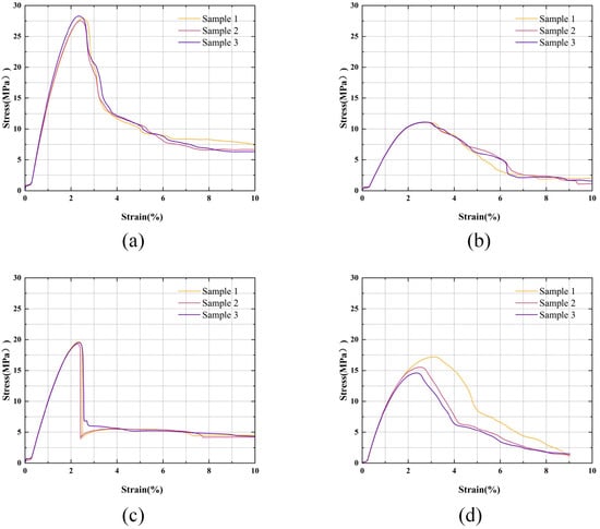
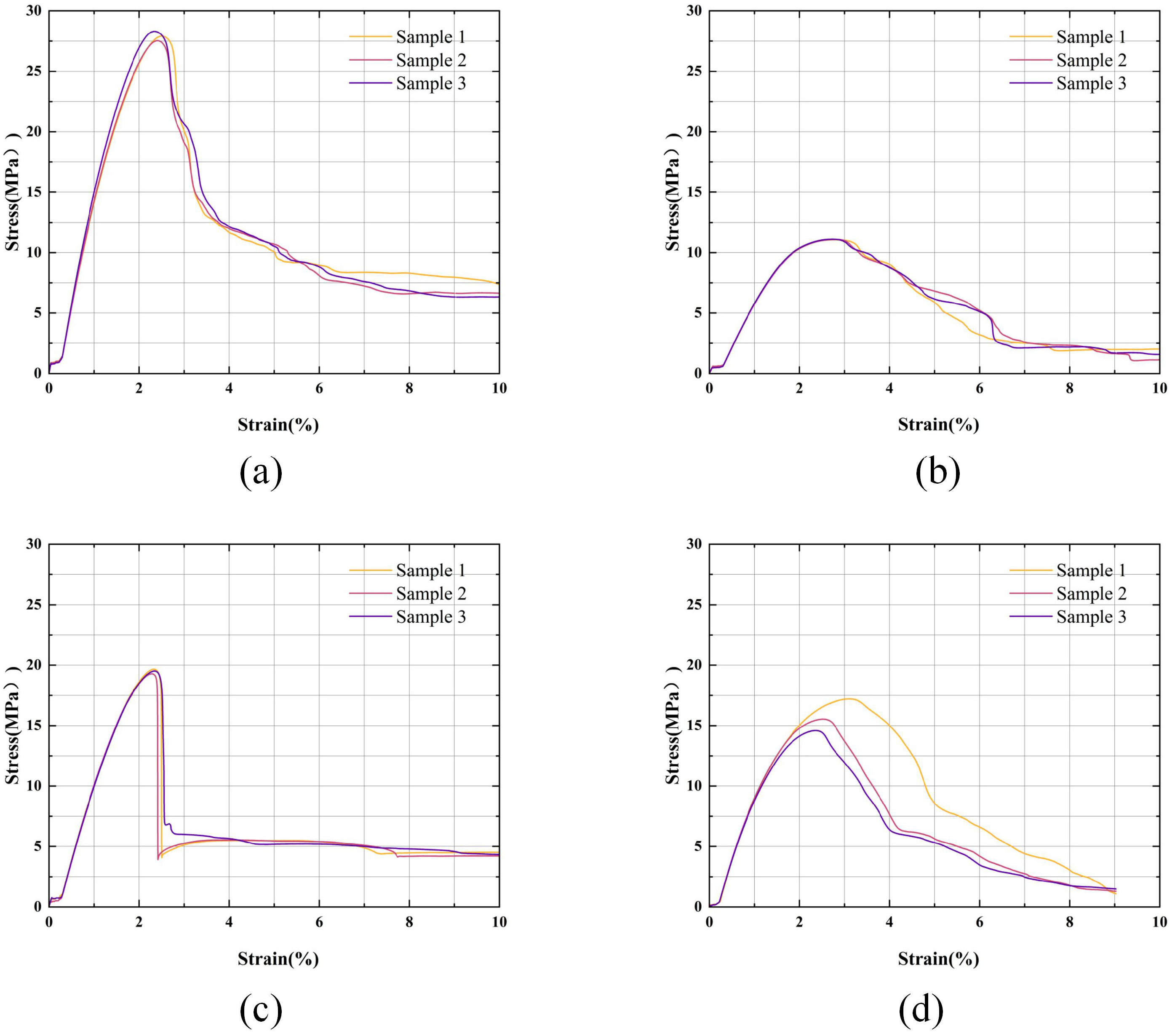
Quasi-static tensile tests under simulated multi-domain load spectra, employing stepwise loading, were conducted to evaluate the topology-optimized (TO), honeycomb-filled (HC), central lightening hole (ES), and Solid Baseline (SB) configurations. Deformation was monitored until the crosshead displacement reached 10 mm, revealing fundamental differences in load efficiency, failure modes, and energy absorption among the configurations. As shown in Figure 7, the elastic moduli (TO: 2234.3 ± 76.2 MPa; ES: 1726.9 ± 178.2 MPa; SB: 1400.0 ± 47.4 MPa; HC: 886.0 ± 16.6 MPa) directly reflect their respective deformation and energy absorption behaviors.
Figure 7.
Tensile stress–strain curves of different configurations: (a) TO; (b) HC; (c) ES; (d) SB.
The topology-optimized configuration establishes the most efficient load-bearing network along primary force-transfer paths through intelligent material distribution. Its stress–strain curve exhibits the steepest initial slope (elastic modulus: 2234.254 ± 76.179 MPa), significantly exceeding other configurations. This maximum initial gradient directly correlates with superior structural stiffness and rapid stress-response capability during elastic deformation, validating that optimized material allocation along primary load paths maximizes force-transmission efficiency. Post peak strength, the curve demonstrates a gradual strength degradation profile, indicating the multi-path load-transfer architecture sustains substantial load-bearing capacity beyond material yielding.
The ES configuration demonstrates a lower initial slope (elastic modulus: 1726.861 ± 178.221 MPa) than the TO configuration, yet retains substantial stiffness indicative of competent load-bearing capacity. Near peak strength, its curve exhibits an abrupt transition to negative slope values, signifying rapid load-bearing capacity deterioration due to stress concentration around the central lightening hole, highlighting inherent defect sensitivity in stress-riser geometries.
The SB configuration displays a moderate elastic slope (1399.922 ± 47.371 MPa), revealing suboptimal stiffness efficiency in uniform cross-section designs. Post-peak degradation features irregular slope fluctuations, correlating with heterogeneous fracture progression induced by process defects.
Conversely, the HC configuration manifests distinctive slope characteristics: an initial plateau (elastic modulus: 886.007 ± 16.639 MPa) reflects low-stiffness porous topology, followed by an extended plastic plateau with near-zero slope over significant strain intervals, demonstrating stable energy dissipation through progressive cell-wall yielding.
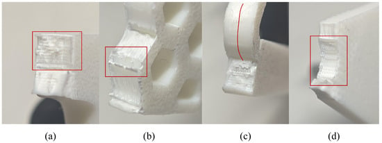
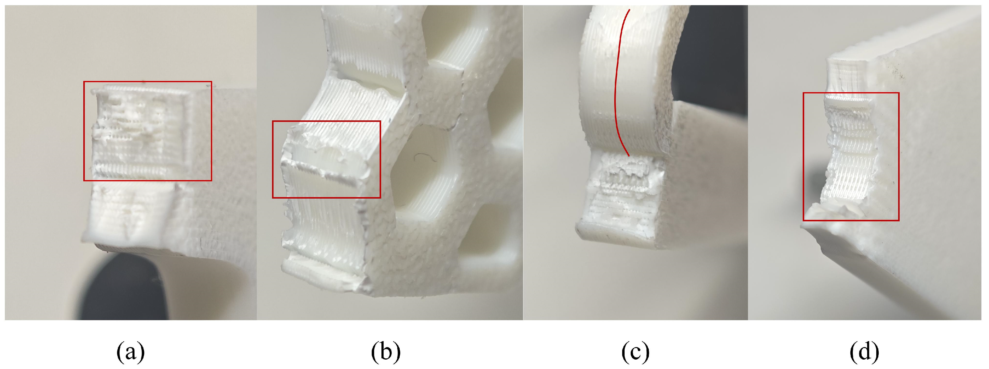
Specific Energy Absorption (SEA), quantified as the energy absorbed per unit volume (J/m3), was calculated through stress–strain curve integration, making it an essential metric for evaluating lightweighting achievements. The mechanistic superiority of the TO configuration in SEA (72% higher than HC) is primarily attributed to its volume-maximized plastic dissipation mechanism. Instead of experiencing localized stress singularities like the ES configuration, the TO structure leverages the SIMP algorithm’s inherent characteristic of homogenizing strain energy density. Under tensile loading, the macroscopic optimized branches act as a truss network that effectively decomposes complex bending moments into uniform axial tension and compression vectors along the struts. This structural conversion delays the onset of localized necking and plastic hinges. When the primary load-bearing ligament reaches its yield strength, the topology’s inherent redundancy mechanically redistributes the stress flow to the secondary struts. Consequently, this multi-path load transfer prevents immediate crack propagation and forces a larger volumetric fraction of the PLA material to undergo stable plastic yielding before ultimate failure, quantitatively resulting in the exceptional SEA of 742 J/m3. This fundamental difference in deformation mechanics explains the substantial quantitative advantage: TO achieves a 72% higher SEA than HC (431.725 J/m3) and a 20% advantage over ES (620.051 J/m3), despite all three targeting comparable mass reduction (~30.8%), as detailed in Table 3. These results strongly suggest that the AM-constrained TO approach uniquely resolves the performance compromise inherent in conventional lightweight design (HC, ES). Although the HC configuration exhibited progressive collapse characteristics, its SEA was significantly compromised (431.725 J/m3, 18.6% lower than SB). This performance deficit is a direct consequence of the inherent interlayer weakness in FDM-fabricated cellular structures, a well-documented limitation of the process. The FDM process induces significant thermomechanical residual stresses due to non-uniform thermal gradients and constrained cooling during layer deposition, which critically undermines the bonding quality between adjacent filaments [26]. As evidenced by studies on Fused Filament Fabrication (FFF, also known as Fused Deposition Modeling or FDM) of PLA, insufficient fusion at the interfaces between deposited roads creates microscopic voids and preferential delamination paths [27]. In our HC specimens, these weak interfacial bonds—where the tensile strength perpendicular to the build direction is typically only 50–70% of the bulk material strength [28]—restrict effective stress transfer and plastic deformation to localized layer zones. This prevents the full engagement of the honeycomb network as a cohesive, energy-dissipating unit. Computational and theoretical studies on honeycomb mechanics further affirm that the mechanical performance, including energy absorption, is highly sensitive to the integrity of the nodal connections and strut walls, which are precisely the features most vulnerable to FDM-induced defects [29]. Consequently, energy dissipation in the HC configuration is dominated by progressive interlayer debonding and localized fracture at cell wall junctions (as seen in Figure 8f and Figure 9b), rather than the global, stable buckling of the cellular architecture. This shift in failure mechanism fundamentally limits the SEA enhancement, demonstrating how manufacturing constraints can offset the theoretical lightweighting and energy-absorption potential of periodic lattice structures.
Table 3.
Tensile test performance parameters.
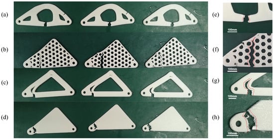
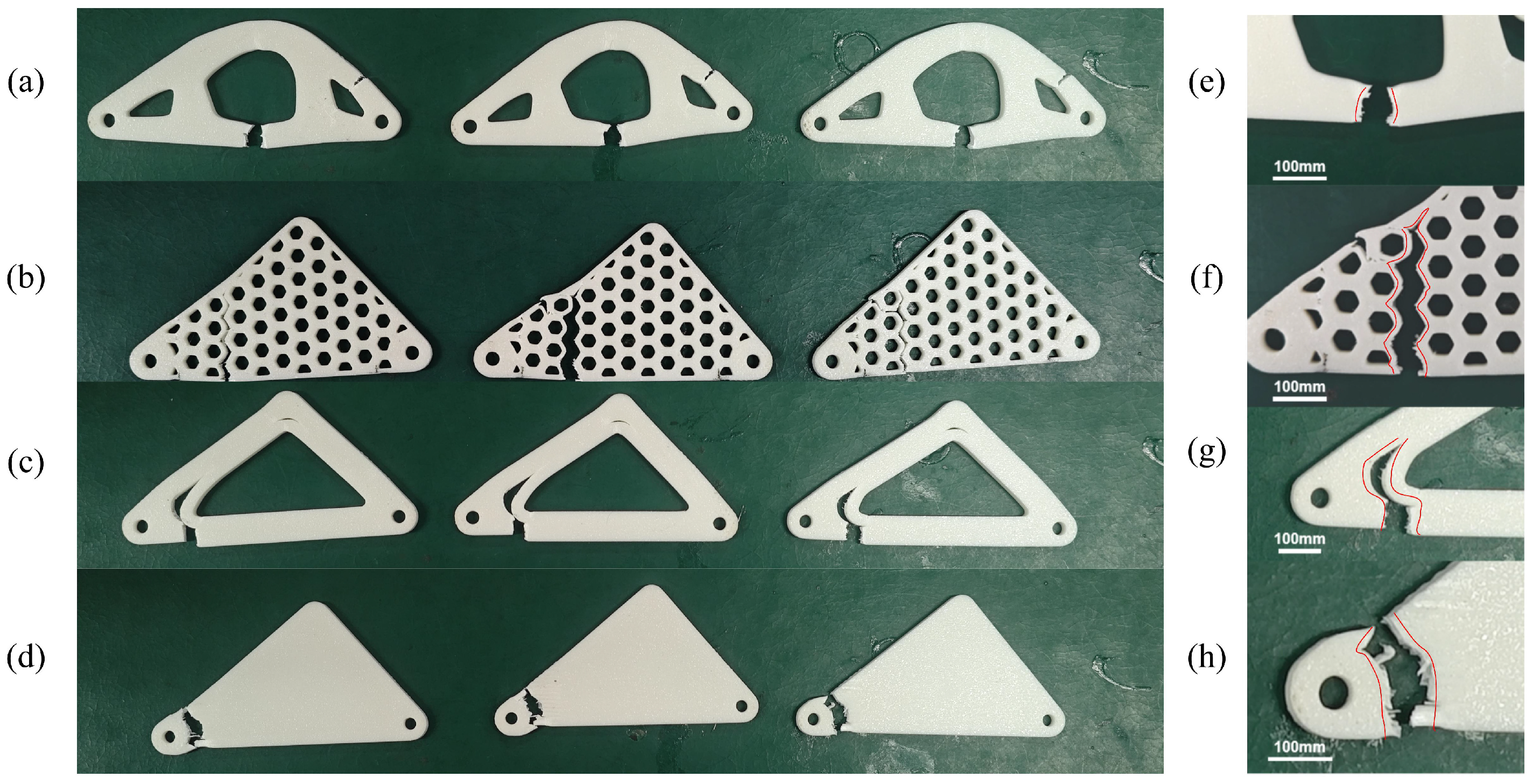
Figure 8.
Tensile Failure Modes of (a) TO, (b) HC, (c) ES, and (d) SB Configurations; magnified crack morphology of (e) TO, (f) HC, (g) ES, and (h) SB configurations.
Figure 9.
Fracture Morphologies of (a) TO, (b) HC, (c) ES, and (d) SB Configurations.
Fractographic analysis (Figure 8e–h) systematically reveals how topological configuration interacts with manufacturing defects to govern failure modes. The topology-optimized (TO) design (Figure 8e and Figure 9a) exhibited a fracture dominated by its intentional structure, featuring dual cracks propagating linearly along optimized trajectories aligned with principal stress paths. Conversely, the honeycomb-filled (HC) configuration (Figure 8f and Figure 9b) displayed failure dictated by manufacturing limitations, with cracks propagating preferentially along FDM-fabricated interlayer interfaces, leading to cell wall delamination—a clear indicator that insufficient interlayer bonding critically constrains energy absorption in this porous structure. The central lightening hole (ES) configuration (Figure 8g and Figure 9c) demonstrated a synergistic interplay of geometric and manufacturing weaknesses: cracks initiated at stress concentrations around the hole periphery, exhibiting brittle fracture surfaces, before propagating along the weaker interlayer interfaces, thereby accelerating failure. Finally, the Solid Baseline (SB) configuration (Figure 8h and Figure 9d) showed fracture dominated by manufacturing defects, characterized by rough, serrated surfaces and crack paths guided by interlayer interfaces and internal microdefects after initiation at hole edges.
Fractographic evidence across configurations demonstrates that topological optimization effectively governs load transfer pathways. Honeycomb structures exhibit pronounced susceptibility to manufacturing constraints. Center-drilled designs amplify the impact of manufacturing defects, while solid reference configurations fully expose the inherent stochasticity of manufacturing processes. This provides an empirical basis for configuration selection and process refinement.
Based on comprehensive performance analysis, the four configurations exhibit distinct application-specific adaptation profiles in engineering practice. The topologically optimized configuration demonstrates superior balance in the strength–stiffness–energy absorption triad (highest Specific Energy Absorption) and lightweight efficacy (30.8% mass reduction), efficiently managing complex dynamic loads through multi-path load transfer mechanisms. This renders it ideal for mission-critical components like amphibious UAV rotary arms under multi-condition service. The honeycomb-filled configuration’s unique progressive failure mode holds theoretical value for dedicated energy absorption scenarios (landing gear buffers), yet its practical performance is significantly constrained by FDM process limitations. Potential realization requires optimized printing parameters or higher-bonding-strength processes (SLS). The central lightening hole configuration’s (ES) high static strength is only suitable for non-critical static locations with low-cycle fatigue and negligible impact. Its central void-induced brittle failure propensity poses risks under dynamic loading. The solid reference configuration primarily serves as a performance benchmark, empirically validating the imperative for material efficiency enhancement via topological optimization.
In summary, the topologically optimized configuration demonstrates outstanding advantages in FDM manufacturability, multi-objective performance, and complex load adaptability, whereas deploying non-optimized configurations requires meeting specific prerequisites.
3.2. Finite Element Verification Results
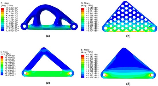
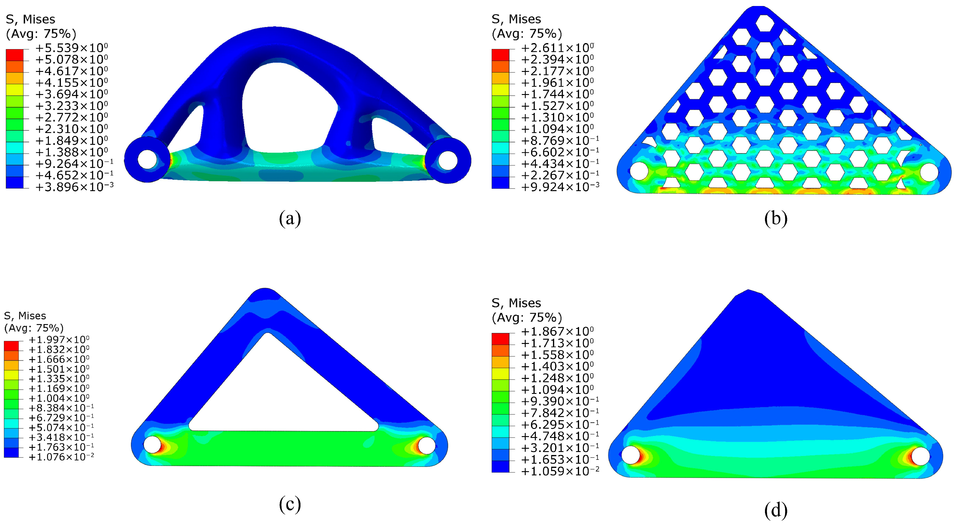
To validate the design and gain deeper insights into the stress distribution of distinct lightweight configurations under specified loading, this study conducted systematic finite element analysis (FEA). Figure 10 presents von Mises stress contour plots for all four configurations under identical 500 N tensile loading.
Figure 10.
Von Mises stress distribution under 500 N tensile load for (a) TO, (b) HC, (c) ES, and (d) SB Configurations.
Analysis reveals that the topologically optimized (TO) configuration (Figure 10a) exhibits the most uniform low-stress distribution (predominant blue zones), with peak von Mises stress limited to 5.539 MPa. This stress concentration primarily localizes at the peripheral edges of bolt connection holes, while no significant stress concentrations were observed throughout the structure. This empirically validates the demonstrated efficacy of topological optimization in achieving uniform load distribution and enhanced structural efficiency. In contrast, the honeycomb-filled configuration (HC, Figure 10b) manifests pronounced stress gradients, with distinct localized high-stress zones (yellow/red) within the structure. Its peak von Mises stress reaches 2.611 MPa, concentrated predominantly at nodal junctions of cellular walls. This constitutes a characteristic stress concentration phenomenon, correlating directly with the configuration’s diminished tensile strength and premature failure observed in testing. The central lightening hole configuration (ES, Figure 10c) demonstrates predominantly blue-green stress levels overall, yet exhibits intensely concentrated red/yellow high-stress patches adjacent to the bottom hole periphery. Its peak von Mises stress registers at 1.997 MPa (slightly exceeding other configurations), clearly indicating significant stress concentration effects induced by the hole edge. This finding directly elucidates why, despite potentially higher global stiffness in testing, the configuration exhibited characteristic brittle fracture. Furthermore, analysis of the solid triangular configuration (SB, Figure 10d) indicates its peak von Mises stress registers at 1.865 MPa, with high-stress zones (red) markedly concentrated in the central basal region. This manifests stress concentration issues inherent to unoptimized solid structures, attributable to inadequate load path diversification.
Collectively, the finite element analysis (FEA) results in Figure 10 strongly indicate key mechanical response characteristics across distinct lightweighting strategies, particularly regarding stress concentration loci and intensity. These findings demonstrate strong concordance with failure modes observed in tensile testing. It is critical to emphasize that FEA computes stress distributions under working loads (500 N), whereas tensile testing measures the ultimate load capacity of structures. These approaches provide complementary technical perspectives (stress distribution characteristics vs. final strength limits) for configuration performance evaluation.
4. Discussion
Building upon the experimental and computational results presented in Section 3, this section provides a comprehensive discussion of their significance. We examine the performance of the AM-constrained TO design by benchmarking it against relevant literature (Section 4.1). The underlying mechanisms responsible for the observed enhancements in stiffness, strength, and energy absorption are analyzed in detail (Section 4.2). The critical importance of incorporating FDM manufacturing constraints during optimization is highlighted as a key innovation (Section 4.3). Furthermore, a comparative assessment of the TO, HC, and ES lightweighting strategies is conducted (Section 4.4), followed by a discussion on the validation approaches (Section 4.5). Finally, the limitations of this work and potential future research directions are outlined (Section 4.6).
4.1. Performance Benchmarking Against Existing Literature
This study validates the transformative potential of additive manufacturing-constrained topology optimization (AM-constrained TO) for lightweight design of critical load-bearing UAV components. The core finding—achieving a 30.8% mass reduction alongside simultaneous improvements in stiffness (+59.6%), tensile strength (+77.0%), and Specific Energy Absorption (+40.0%)—represents a “dual-performance breakthrough” that remains rare in existing literature. From a benchmarking perspective, prior studies in the TO + AM lightweighting domain have primarily pursued mass reduction targets with insufficient attention to simultaneous mechanical property enhancement. Zhu et al. (2021) noted that “mass reductions of 20–50% are commonly reported” while acknowledging that “achieving optimal designs satisfying manufacturing constraints remains a key challenge.” [24]. The present study achieves extra performance gains within the same mass reduction range, demonstrating that AM-constrained TO’s value lies not only in enabling direct manufacturing of optimized results, but in guiding the algorithm to discover high-performance topologies that transcend conventional design intuition.
Wang et al. (2026) reported an AM-constrained optimization method for UAV arms, incorporating material anisotropy and minimum feature size constraints, achieving ~50% mass reduction while maintaining stiffness (compliance increased by 32.46%) [30]. The distinction lies in optimization objectives: Wang et al. balanced mass reduction and stiffness preservation, whereas the present study improves all mechanical properties under a 30.8% mass reduction target, achieving a 59.6% stiffness improvement rather than merely retaining the original level. Top et al. (2025) compared SIMP and BESO methods on UAV catapult brackets, demonstrating that at high mass reduction targets, algorithm choice significantly affects performance; their extreme 70% reduction cases inversely validate the reasonableness of the present study’s 30.8% target, which balances substantial lightweighting with stable mechanical performance [31].
4.2. Deep Mechanistic Analysis of Mechanical Property Enhancement
The TO configuration achieved a stiffness of 2234 MPa (+59.6% vs. SB) because the SIMP algorithm strategically aggregated material along principal stress trajectories, forming optimal load transfer paths. In contrast, the HC configuration’s hexagonal grid followed fixed geometric rules that could not adapt to local stress levels, resulting in extensive low-stress “ineffective zones” in the tensile direction and an overall stiffness of only 39.6% of TO. The TO configuration’s tensile strength reached 27.9 MPa (+77.0%), outperforming ES (19.489 MPa) and HC (11.5 MPa). While ES ranked second nominally, stress concentration at the hole perimeter limited its ultimate capacity; HC adopted a vertical printing strategy with interlayer bonding interfaces perpendicular to the tensile load, resulting in cracking and an ultimate strength of only 41.2% of TO. Kumar et al. (2019) demonstrated that the relative orientation between printing direction and loading direction critically determines the ultimate strength of 3D-printed structures—FDM’s inherent interlayer bonding anisotropy imposes a systematic constraint on tensile performance perpendicular to build layers, a limitation that TO optimization circumvents by eliminating horizontal interlayer interfaces and reorienting material toward continuous Z-axis fiber paths [20].
The TO configuration’s SEA reached 742 J/m3 (+40.0%), surpassing ES by 20% and HC by 72%—the most pronounced TO advantage in this study. The mechanism is that the topology-optimized continuous structure engaged a larger material volume in stable energy dissipation throughout deformation; ES suffered localized necking due to stress concentration, and HC experienced brittle interlayer delamination—both losing load-bearing capacity before energy absorption was fully developed. Since SEA equals total energy absorbed before fracture divided by structural mass, the TO configuration’s homogenized stress distribution and delayed fracture onset significantly increased total energy absorption.
4.3. Distinctive Advantages of FDM Manufacturing Constraint Integration
The core innovation of this study lies in explicitly integrating the FDM Z-axis extrusion constraint into the SIMP optimization framework. Even theoretically optimal TO designs often contain large overhang features (>45 deg) requiring extensive support structures for FDM manufacturing, increasing post-processing cost, and introducing weak bonding at support–workpiece interfaces. By incorporating the Z-axis extrusion constraint explicitly into sensitivity analysis, the present method guarantees that all optimized topology features satisfy direct FDM printability requirements (no support needed), fundamentally resolving this dilemma. Zhu et al. (2021) characterized this as “one of the core difficulties in AM-constrained TO” and identified “explicit constraint modeling as the key direction”—the present study represents a substantive step along this path [24]. Additionally, FDM’s layer-by-layer nature naturally aligns print paths with the Z-axis; through constraint-driven optimization, the TO configuration’s load-bearing members form continuous, uninterrupted Z-axis structures, avoiding interlayer interfaces as weak zones. Wang et al. (2026) addressed interlayer weakness via material anisotropy constraints, whereas the present geometric constraint approach directly guarantees continuity, sidestepping material anisotropy penalties while simplifying the optimization model [30].
4.4. Systematic Comparison with Conventional Lightweighting Strategies
This study systematically compared three mainstream lightweighting strategies—AM-constrained TO, Hexagonal Honeycomb infill (HC), and central lightening holes (ES)—under comparable mass reduction targets. The HC strategy excels under in-plane compression but demonstrated significantly inferior axial tensile properties (stiffness 886 MPa, SEA 432 J/m3), primarily due to FDM inter-layer bonding limitations. Yao et al. (2026) similarly found that hole-based lightweighting designs face inherent performance boundaries in improving stress distribution in rotary joints—a finding consistent with the present study’s ES observations [13]. The ES strategy performed well in tensile strength (19.489 MPa) but suffered from unavoidable energy absorption penalties due to geometric stress concentration; Kumar et al. (2019) reported that geometric stress concentration diminishes SEA far more severely than anticipated, explaining why ES’s SEA (620 J/m3) reached only 83.6% of TO [20]. The TO strategy’s systematic superiority stems from data-driven material layout optimization: the algorithm globally searches the design domain under mass constraint rather than relying on heuristic geometric assumptions, ensuring that material density at each local position is precisely matched to local stress level, achieving a global—rather than merely local—optimum.
4.5. Complementary Validation by FEA and Tensile Testing
This study employed both finite element analysis (von Mises stress distributions under working load of 500 N) and quasi-static tensile testing, providing cross-validation from complementary perspectives. FEA revealed distinct stress characteristics: TO exhibited the most uniform stress field, ES showed pronounced concentration at the hole perimeter, and HC displayed significant non-uniformity. These predictions aligned closely with failure modes observed in tensile testing—necking at the ES hole edge and interlayer delamination in HC—confirming model reliability. Top et al. (2025) similarly adopted a dual numerical–experimental strategy, emphasizing that experimental validation is essential for confirming AM-manufactured topology-optimized structural performance [31]. The present study further demonstrates this: deviations in numerical predictions—such as underestimation of stress at the ES hole edge—were corrected through tensile testing, constituting a complete evidence chain from design to validation.
4.6. Limitations and Future Research Directions
Despite substantive progress, several limitations warrant future investigation. The present study used PLA via FDM, constrained by PLA’s brittle behavior and FDM inter-layer bonding anisotropy; extension to metal AM (e.g., SLM-fabricated Ti-6Al-4V or AA7075) requires further validation. Top et al. (2025) demonstrated BESO achieving 51% volume reduction via SLM, indicating promising metal AM prospects [31]. Future work can introduce multi-objective optimization frameworks to explore Pareto fronts among mass, stiffness, and natural frequency, addressing diverse engineering requirements. Most critically, UAV rotary arms are subjected to cyclic alternating loads during flight, yet this study addressed only quasi-static tensile loading. Top et al. (2025) have conducted fatigue validation on UAV brackets, indicating that the fatigue performance of topology-optimized designs warrants in-depth investigation [31]. Future work should build upon this foundation with high-cycle fatigue testing and develop fatigue life prediction models for TO configurations under cyclic loading, establishing a complete methodology from static design to fatigue life assessment.
5. Conclusions
This study establishes a transformative paradigm for lightweight design of critical UAV components through additive manufacturing-constrained topology optimization (AM-constrained TO). The core innovation lies in the explicit integration of Fused Deposition Modeling (FDM) constraints directly into the optimization formulation, enabling the generation of intrinsically efficient load-bearing architectures. The key conclusions are summarized as follows:
- (1)
- Dual-performance breakthrough: The AM-constrained TO approach achieved a 30.8% mass reduction while simultaneously enhancing mechanical properties—an outcome unattainable by conventional lightweight strategies (HC and ES). The TO configuration exhibited superior stiffness (2234 ± 76 MPa, +59.6% vs. SB) and Specific Energy Absorption (742 ± 29 J/m3, +40.0% vs. SB), resolving the traditional trade-off between mass reduction and structural performance.
- (2)
- Mechanistic superiority: The optimized topology transforms the global bending compliance into localized axial tension/compression networks. By aligning material aggregation strictly with principal stress trajectories and mitigating FDM inter-layer weaknesses through continuous strut paths, the TO design maximizes strain energy uniformization. This biomechanically efficient skeleton prevents localized plastic hinges, enabling sustained volumetric yielding that dictates its quantitative superiority in SEA over conventional cellular or drilled configurations.
- (3)
- Manufacturing feasibility: By incorporating FDM extrusion constraints during optimization, the TO design eliminated unfabricable overhangs while maintaining structural integrity. This demonstrates the critical importance of co-optimizing design and manufacturing constraints for functional components.
- (4)
- Practical validation: Tensile tests and FEA confirmed the TO configuration’s exceptional performance under operational loads. Its multi-path failure mode (Figure 8a and Figure 9a) contrasts sharply with the interlayer-delamination failure of HC and stress-concentration-induced brittle fracture of ES.
This work provides a validated methodology for designing high-performance, additively manufactured load-bearing structures. Future research will explore multi-physics constraints (thermal/aeroelastic) and advanced metamaterial integration for next-generation amphibious UAVs.
Author Contributions
Methodology, Y.C. and M.R.; software, Y.C.; validation, Y.C. and S.L.; formal analysis, Y.C. and M.R.; investigation, Y.C.; writing—original draft preparation, Y.C.; writing–review and editing, M.R., S.L. and Y.D. All authors have read and agreed to the published version of the manuscript.
Funding
The work was supported by the School of Aeronautics at Chongqing Jiaotong University. (No. X202510618105).
Data Availability Statement
The data presented in this study are available on request from the first author.
Conflicts of Interest
The authors declare that they have no known competing financial interests or personal relationships that could influence the work reported in this paper.
Abbreviations
The following abbreviations are used in this manuscript:
| TO | Topology Optimization |
| HC | Hexagonal Honeycomb Infill |
| ES | Central Lightening Hole |
| SB | Solid Baseline |
| FDM | Fused Deposition Modeling |
| FEA | Finite Element Analysis |
| SEA | Specific Energy Absorption |
| PLA | Polylactic Acid |
| SIMP | Solid Isotropic Material with Penalization |
References
- Sun, J.; Yuan, G.; Song, L.; Zhang, H. Unmanned Aerial Vehicles (UAVs) in Landslide Investigation and Monitoring: A Review. Drones 2024, 8, 30. [Google Scholar] [CrossRef] [Scilit]
- Tomic, T.; Schmid, K.; Lutz, P.; Domel, A.; Kassecker, M.; Mair, E.; Grixa, I.; Ruess, F.; Suppa, M.; Burschka, D. Toward a Fully Autonomous UAV: Research Platform for Indoor and Outdoor Urban Search and Rescue. IEEE Robot. Autom. Mag. 2012, 19, 46–56. [Google Scholar] [CrossRef] [Scilit]
- Shakhatreh, H.; Sawalmeh, A.H.; Al-Fuqaha, A.; Dou, Z.; Almaita, E.; Khalil, I.; Othman, N.S.; Khreishah, A.; Guizani, M. Unmanned Aerial Vehicles (UAVs): A Survey on Civil Applications and Key Research Challenges. IEEE Access 2019, 7, 48572–48634. [Google Scholar] [CrossRef] [Scilit]
- Nex, F.; Remondino, F. UAV for 3D mapping applications: A review. Appl. Geomat. 2014, 6, 1–15. [Google Scholar] [CrossRef] [Scilit]
- Xing, S.; Zhang, X.; Tian, J.; Xie, C.; Chen, Z.; Sun, J. Morphing Quadrotors: Enhancing Versatility and Adaptability in Drone Applications—A Review. Drones 2024, 8, 762. [Google Scholar] [CrossRef] [Scilit]
- Patnaik, K.; Zhang, W. Towards reconfigurable and flexible multirotors. Int. J. Intell. Robot. Appl. 2021, 5, 365–380. [Google Scholar] [CrossRef] [Scilit]
- Mintchev, S.; Floreano, D. Adaptive Morphology: A Design Principle for Multimodal and Multifunctional Robots. IEEE Robot. Autom. Mag. 2016, 23, 42–54. [Google Scholar] [CrossRef] [Scilit]
- Wu, Y.Z.; Yang, F.; Wang, Z.; Wang, K.W.; Cao, Y.J.; Xu, C.; Gao, F. Ring-Rotor: A Novel Retractable Ring-Shaped Quadrotor with Aerial Grasping and Transportation Capability. IEEE Robot. Autom. Lett. 2023, 8, 2126–2133. [Google Scholar] [CrossRef] [Scilit]
- Xu, M.X.; De, Q.X.; Yu, D.F.; Hu, A.; Liu, Z.; Wang, H.S. Biomimetic Morphing Quadrotor Inspired by Eagle Claw for Dynamic Grasping. IEEE Trans. Robot. 2024, 40, 2513–2528. [Google Scholar] [CrossRef] [Scilit]
- Mintchev, S.; Floreano, D. A multi-modal hovering and terrestrial robot with adaptive morphology. In Proceedings of the 2nd International Symposium on Aerial Robotics, Philadelphia, PA, USA, 11–12 June 2018. [Google Scholar]
- Falanga, D.; Kleber, K.; Mintchev, S.; Floreano, D.; Scaramuzza, D. The Foldable Drone: A Morphing Quadrotor That Can Squeeze and Fly. IEEE Robot. Autom. Lett. 2019, 4, 209–216. [Google Scholar] [CrossRef] [Scilit]
- Yang, X.; Wang, T.; Liang, J.; Yao, G.; Liu, M. Survey on the novel hybrid aquatic–aerial amphibious aircraft: Aquatic unmanned aerial vehicle (AquaUAV). Prog. Aerosp. Sci. 2015, 74, 131–151. [Google Scholar] [CrossRef] [Scilit]
- Yao, C.; Dong, W.; Zhang, X.; Cui, X.; Niu, Z.; Li, Z.-Y.; Zhao, J.; Yan, D.; Li, H. Fatigue Life and Lightweight Design of Demolition Robot Rotary Joint Based on Topology Optimization. Machines 2026, 14, 154. [Google Scholar] [CrossRef] [Scilit]
- Fan, D.D.; Thakker, R.; Bartlett, T.; Ben Miled, M.; Kim, L.; Theodorou, E.; Agha-mohammadi, A.A. Autonomous Hybrid Ground/Aerial Mobility in Unknown Environments. In Proceedings of the IEEE/RSJ International Conference on Intelligent Robots and Systems (IROS), Macau, China, 4–8 November 2019; IEEE: Piscataway, NJ, USA, 2019; pp. 3070–3077. [Google Scholar]
- Kalantari, A.; Touma, T.; Kim, L.; Jitosho, R.; Strickland, K.; Lopez, B.T.; Agha-Mohammadi, A.A. Drivocopter: A concept Hybrid Aerial/Ground vehicle for long-endurance mobility. In Proceedings of the IEEE Aerospace Conference, Big Sky, MT, USA, 6–13 March 2020; IEEE: Piscataway, NJ, USA, 2020. [Google Scholar]
- Ben David, N.; Zarrouk, D. Design and Analysis of FCSTAR, a Hybrid Flying and Climbing Sprawl Tuned Robot. IEEE Robot. Autom. Lett. 2021, 6, 6188–6195. [Google Scholar] [CrossRef] [Scilit]
- Guo, X.; Zhu, M.; Tian, Y. L-BIRD: Lightweight Bio-Inspired Rotary-Wing Drone. IEEE Robot. Autom. Lett. 2026, 11, 186–193. [Google Scholar] [CrossRef] [Scilit]
- Guo, C.; Song, W.; Dai, Z. Structural design inspired by beetle elytra and its mechanical properties. Chin. Sci. Bull. 2012, 57, 941–947. [Google Scholar] [CrossRef] [Scilit]
- Ghoddousi, S.; Mohammadnejad, M.; Safarabadi, M.; Haghighi-Yazdi, M. Compression response of nature-inspired metamaterials based on Fibonacci spiral. Int. J. Mech. Sci. 2025, 285, 109853. [Google Scholar] [CrossRef] [Scilit]
- Kumar, S.; Ubaid, J.; Abishera, R.; Schiffer, A.; Deshpande, V.S. Tunable Energy Absorption Characteristics of Architected Honeycombs Enabled via Additive Manufacturing. ACS Appl. Mater. Interfaces 2019, 11, 42549–42560. [Google Scholar] [CrossRef] [Scilit]
- Tang, T.S.; Wang, L.J.; Zhu, M.Q.; Zhang, H.Z.; Dong, J.R.; Yue, W.H.; Xia, H. Topology Optimization: A Review for Structural Designs Under Statics Problems. Materials 2024, 17, 5970. [Google Scholar] [CrossRef] [Scilit]
- Sigmund, O.; Maute, K. Topology optimization approaches. Struct. Multidiscip. Optim. 2013, 48, 1031–1055. [Google Scholar] [CrossRef] [Scilit]
- Zhu, J.-H.; Zhang, W.-H.; Xia, L. Topology Optimization in Aircraft and Aerospace Structures Design. Arch. Comput. Methods Eng. 2015, 23, 595–622. [Google Scholar] [CrossRef] [Scilit]
- Zhu, J.H.; Zhou, H.; Wang, C.; Zhou, L.; Yuan, S.Q.; Zhang, W.H. A review of topology optimization for additive manufacturing: Status and challenges. Chin. J. Aeronaut. 2021, 34, 91–110. [Google Scholar] [CrossRef] [Scilit]
- Cai, Y.; Su, G.; Zhao, J.; Feng, S. The Coupled Wing Morphing of Ornithopters Improves Attitude Control and Agile Flight. Machines 2024, 12, 486. [Google Scholar] [CrossRef] [Scilit]
- Morvayová, A.; Karamimoghadam, M.; Scolamacchia, L.; Moradi, M.; Casalino, G. Numerical and Experimental Study of PLA Honeycomb-Shaped Lattice Fabricated by Fused Deposition Modeling. Adv. Eng. Mater. 2025, 27, 2500430. [Google Scholar] [CrossRef] [Scilit]
- Gajjar, T.; Yang, R.; Ye, L.; Zhang, Y.X. Effects of key process parameters on tensile properties and interlayer bonding behavior of 3D printed PLA using fused filament fabrication. Prog. Addit. Manuf. 2025, 10, 1261–1280. [Google Scholar] [CrossRef] [Scilit]
- Dizon, J.R.C.; Espera, A.H.; Chen, Q.; Advincula, R.C. Mechanical characterization of 3D-printed polymers. Addit. Manuf. 2018, 20, 44–67. [Google Scholar] [CrossRef] [Scilit]
- Li, X.; Xiong, L.; Li, N.; Fu, J.; Wang, L. Characteristic topological evolution and mechanical behavior analysis of hexagonal honeycomb. J. Braz. Soc. Mech. Sci. Eng. 2025, 47, 428. [Google Scholar] [CrossRef] [Scilit]
- Wang, R.; Yang, W.; Pang, G.; Liu, Z.; Rao, X.; Yu, Y. An integrated method for lightweight design and additive manufacturing of UAV arms. PLoS ONE 2026, 21, e0344000. [Google Scholar] [CrossRef] [Scilit]
- Top, N.; Gökçe, H.; Şahin, İ. Topology Optimization of an Additive Manufactured UAV Catapult Bracket Using SIMP and BESO Methods. Appl. Sci. 2025, 15, 12477. [Google Scholar] [CrossRef] [Scilit]

Disclaimer/Publisher’s Note: The statements, opinions and data contained in all publications are solely those of the individual author(s) and contributor(s) and not of MDPI and/or the editor(s). MDPI and/or the editor(s) disclaim responsibility for any injury to people or property resulting from any ideas, methods, instructions or products referred to in the content. |
© 2026 by the authors. Licensee MDPI, Basel, Switzerland. This article is an open access article distributed under the terms and conditions of the Creative Commons Attribution (CC BY) license.