


Abstract
Planar multi-loop mechanisms often generate a large number of non-isomorphic candidate topological graphs during automatic synthesis, making it difficult to efficiently identify configurations that satisfy engineering-oriented functional requirements. To address this issue, a loop-constrained connectivity calculation method and a connectivity-based localization and screening procedure are proposed. The proposed connectivity calculation is directly formulated for general planar non-fractionated kinematic chains (NFKCs), including those with multiple joints. For planar fractionated kinematic chains (FKCs), however, the present method is not applied directly at the full-system level, but only to decomposed non-fractionated subchains after system-level decomposition. Starting from a structurally admissible set of candidate topological graphs, a connectivity matrix is established for automatic localization of the base and the end-effector (EE). Functional screening is then performed by combining the connectivity criterion with object-oriented rules on hydraulic driving-pair arrangement and driving-redundancy patterns. The method was validated using the 10-link, 3-DOF single-joint equivalent of the KC1 subchain of a mine scaler manipulator arm. Under the prescribed structural and functional constraints, 249 admissible configurations were obtained. The results indicate that the proposed method provides an effective basis for application-oriented topological screening and subsequent dimensional synthesis.
1. Introduction
Mechanism configuration synthesis is fundamental to the design of innovative manipulators and construction machinery [1,2,3,4]. In the application-oriented synthesis of planar multi-loop mechanisms, a large number of non-isomorphic candidate kinematic chains (KCs) may be generated under prescribed structural constraints. To obtain task-feasible mechanisms from such candidates, effective functional screening is required. A key issue in this process is the topological localization of functional roles, especially the base and the end-effector (EE), because actuator arrangement and task realization depend strongly on their relative topological relationship. Therefore, an efficient, robust, and easy-to-implement connectivity calculation method is needed to support base and end-effector (base–EE) localization and subsequent application-oriented screening for planar multi-loop mechanisms [5].
Graph-theoretic representations have been widely used to model planar KCs and to support topological-atlas construction, including systematic enumeration, isomorphism discrimination, and automatic sketching [6,7,8,9]. With advances in computing techniques, these frameworks have been extended to larger link counts, higher degrees of freedom (DOFs), and more complex multi-loop structures, leading to the generation of large numbers of non-isomorphic candidate KCs under structural constraints [10,11,12,13,14,15,16]. However, although these candidates are topologically comprehensive, their functional roles remain undetermined. Therefore, an effective topological metric is still needed to support base–EE localization and efficient application-oriented screening.
Connectivity has been studied as a topology-to-function metric for KCs, especially in task matching and functional-role assignment. Early studies related connectivity to structural variety and used such indices to enumerate chains satisfying prescribed task requirements [17,18]. Subsequently, algorithmic formulations were developed for planar and spatial mechanisms, including virtual-edge-based definitions and procedural strategies such as progressive loop handling and freezing, thereby enabling automated connectivity evaluation [19,20,21]. More recently, matrix-based implementations, such as minimum-mobility and minimum-distance matrices, have further facilitated automated computation and have been extended to mechanisms with multiple joints (MJs), with corresponding engineering validations also reported [22,23]. Despite these advances, two recurring issues remain in the practical application of connectivity to the synthesis of planar multi-loop KCs. First, for planar non-fractionated kinematic chains (NFKCs), the organization of connectivity computation over a main loop and multiple independent loops is often not stated explicitly, reducing implementation clarity and computational robustness. Second, for engineering synthesis involving planar fractionated kinematic chains (FKCs), connectivity has not yet been systematically developed into an operational tool for base–EE localization and actuator-related screening at the decomposed subchain level.
Our previous work on the mine scaler manipulator arm mainly focused on the automatic synthesis of planar FKCs while connectivity was only briefly introduced there as a functional constraint during the screening stage. In contrast, the present study focuses on the connectivity problem itself by developing a loop-constrained connectivity-calculation method together with a connectivity-based localization and screening workflow. Compared with previous studies that addressed connectivity calculation and connectivity-based screening separately, the present work establishes an integrated topological-level framework for planar non-fractionated kinematic chains. More specifically, connectivity evaluation is organized around the main loop and independent loops, and the resulting connectivity matrix is used directly for base–EE localization and rule-based functional screening. The method is formulated for planar non-fractionated kinematic chains, where the connectivity matrix is obtained through a clear and easy-to-implement procedure suitable for batch processing. For planar FKCs, the same framework can be applied after decomposition into non-fractionated subchains, thereby supporting corresponding base–EE localization at the subchain level. The resulting connectivity matrix is further used for automatic base–EE localization and rule-based functional screening within large candidate atlases, including hydraulic driving-pair placement and driving-redundancy pattern identification. A Python 3.12 implementation is developed, and the method is demonstrated using an engineering case, namely, the 10-link, 3-DOF single-joint equivalent of the KC1 subchain of a mine scaler manipulator arm.
The remainder of this paper is organized as follows. Section 2 presents the problem formulation, overall workflow, and input representation of the candidate atlas. Section 3 describes the proposed loop-constrained connectivity calculation. Section 4 introduces the connectivity-based procedure for base–EE localization and functional screening. Section 5 presents the engineering case study together with the corresponding localization and screening results. Section 6 discusses the computational characteristics, screening efficiency, and applicability of the proposed method.
2. Problem Formulation and Input Representation
2.1. Problem Formulation and Workflow Overview
The proposed method is intended for the topological localization and functional screening of planar multi-loop KCs during automatic synthesis. For planar NFKCs, connectivity calculation can be performed directly on the given topological graph. For planar FKCs, system-level decomposition is required first, after which the proposed method can be applied to each decomposed non-fractionated subchain to support corresponding base–EE localization at the subchain level.
From the viewpoint of topology-driven synthesis, the problem addressed in this study can be stated as follows. Given a structurally admissible atlas of non-isomorphic candidate topological graphs, an effective connectivity-calculation method is needed to quantify the topological relationships among vertices and support the automatic localization of functional roles, especially the base and the EE. On this basis, rule-based functional screening can be further carried out to retain candidate configurations that satisfy prescribed application-oriented requirements.
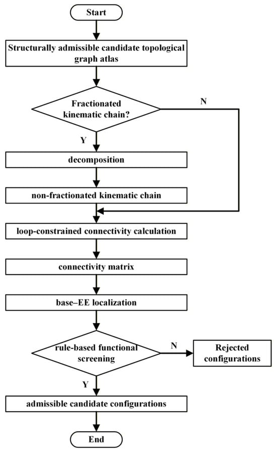
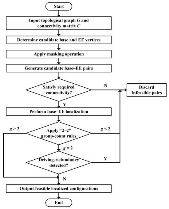
Within this framework, the candidate atlas is regarded as the input design space, whereas connectivity calculation serves as the core topological tool for function-oriented analysis. The resulting connectivity matrix is used not only to determine the relative topological relationship of the base and the EE, but also to support subsequent screening tasks associated with engineering constraints. The overall workflow of the proposed method is illustrated in Figure 1. As shown in the figure, the method can be applied directly to planar NFKCs, whereas planar FKCs must first be decomposed into non-fractionated subchains before connectivity-based localization and functional screening can be carried out.
Figure 1.
Overall workflow of the proposed connectivity-based localization and screening method.
2.2. Structurally Admissible Candidate Atlas and Graph Representation
The proposed method takes as input a candidate topological graph atlas that already satisfies the structural admissibility requirements. Such an atlas consists of non-isomorphic candidate topological graphs retained after structural filtering and isomorphism removal, and it defines the topological design space for subsequent function-oriented analysis and screening.
Each candidate is represented as a planar topological graph, in which vertices denote links and edges denote joints. For planar multi-loop structures, the graph is organized by one main loop together with one or more independent loops. This loop-based representation forms the basis of the proposed connectivity calculation. In particular, the main loop serves as the primary reference for organizing topological relationships, whereas the independent loops are incorporated to complete connectivity evaluation over the entire graph.
For candidate atlases containing MJs, a standard single-joint equivalence treatment is introduced before connectivity calculation so that unified graph representation and matrix-based implementation can be maintained. Unless otherwise specified, all subsequent connectivity calculations and functional screening procedures are performed on these unified topological representations.
3. Loop-Constrained Connectivity Calculation
3.1. Principle and Scope
The proposed method is developed for planar multi-loop KCs, in which the main loop and all independent loops are already available from the preceding topological synthesis procedure, such as candidate-atlas generation, automatic sketching, and structural-constraint filtering [24]. Under this loop-structured representation, connectivity calculation is organized explicitly around the main loop and the independent loops. As a result, the procedure remains loop-aware, easy to implement, and well-suited to the sparse topological graphs encountered in candidate atlases. Therefore, the proposed method is suitable for batch connectivity evaluation over relatively large sets of candidate topological graphs.
3.2. Algorithm and Implementation Overview
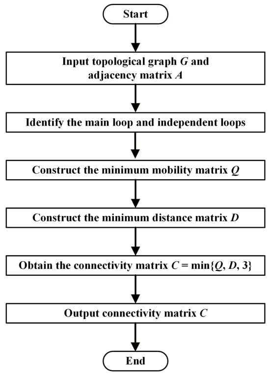
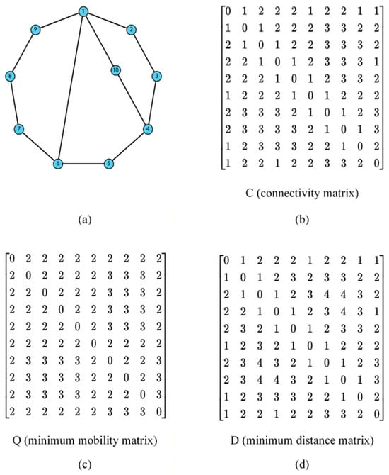
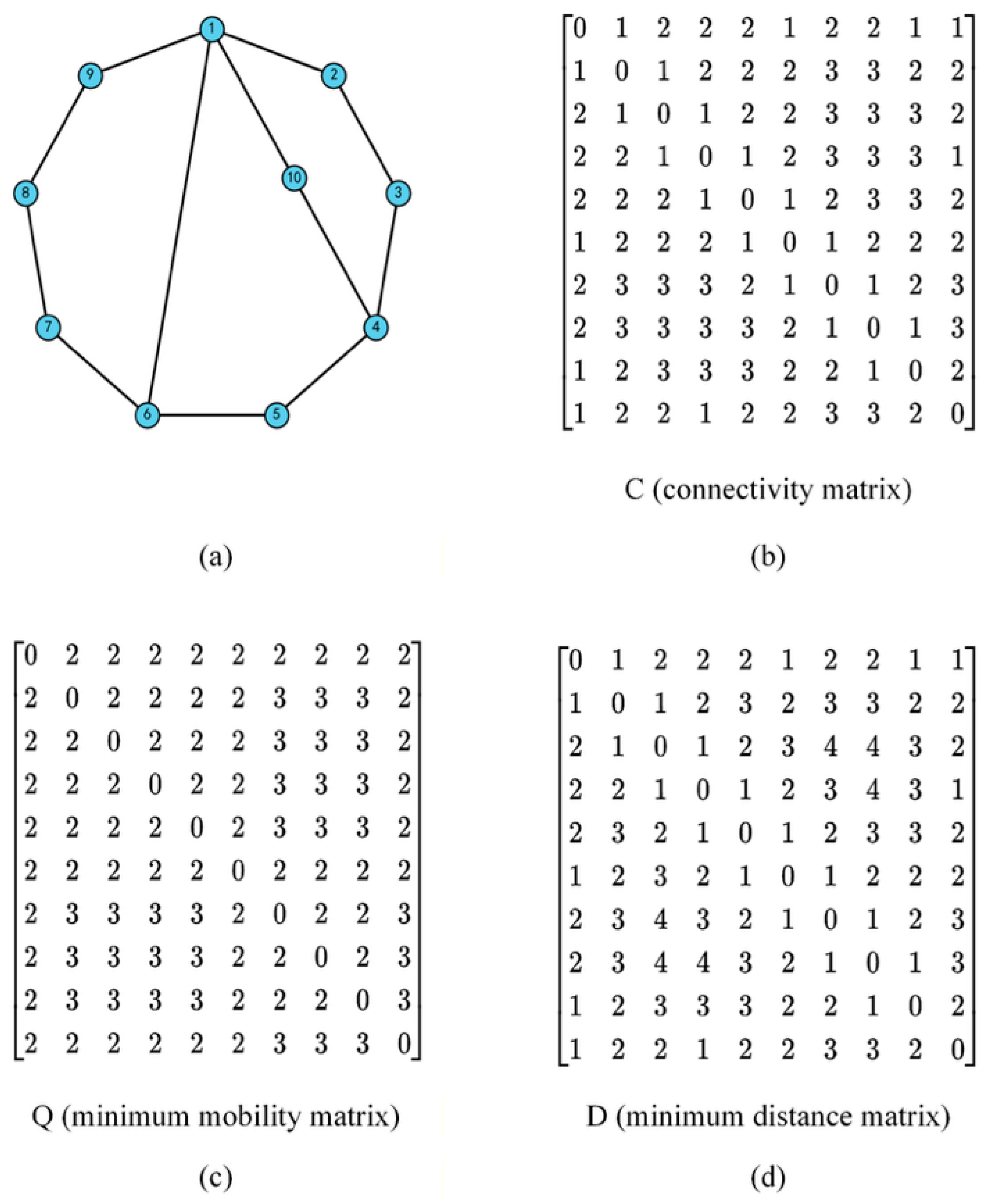
For a planar KC represented by topological graph G with adjacency matrix A, let the numbers of links and DOFs be denoted by N and M, respectively. For clarity and reproducibility, the overall workflow of the proposed connectivity-calculation method is summarized in Figure 2. The calculation is carried out in three steps. Using the topological graph shown in Figure 3a as an illustrative example, the detailed procedure is described below.
Figure 2.
Overall workflow of the proposed connectivity-calculation method.
Figure 3.
(a) A 10-link, 3-DOF topological graph labeled 721-2-12; (b) the connectivity matrix C of (a); (c) the minimum mobility matrix Q of (a); (d) the distance matrix D of (a).
Step 1: Calculation of the minimum mobility matrix.
The minimum mobility matrix Q is calculated as follows.
Step 1.1: Determine the number of independent loops.
The number of independent loops, denoted by L, is obtained from Equation (1).
For the planar KC shown in Figure 3a, and , and thus . The corresponding independent-loop set is
Step 1.2: Construct non-fractionated subchains and calculate their DOFs.
Non-fractionated subchains are constructed by combining the independent loops. Fractionate and duplicate subchains are then removed to obtain the complete set of non-fractionated subchains. For each retained subchain, the DOF is calculated using the planar mobility formula in Equation (3):
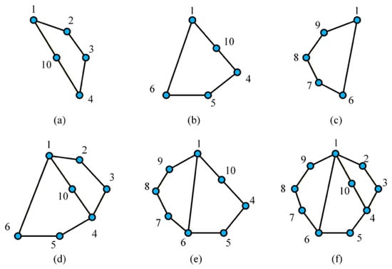
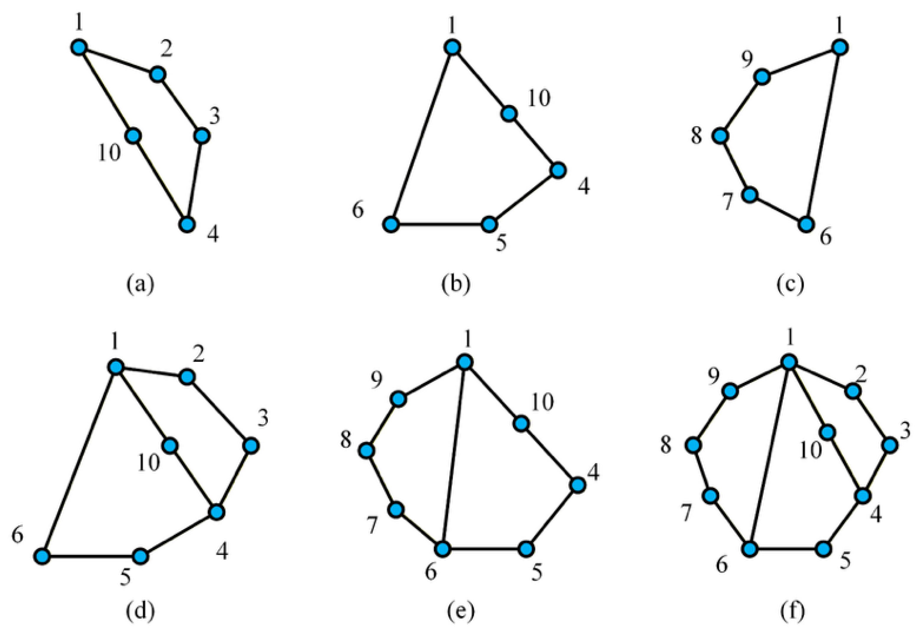
where n is the number of vertices in the subchain and j is the number of edges in the subchain. The resulting subchains of the planar KC in Figure 3a are illustrated in Figure 4.
Figure 4.
Non-fractionated subchains constructed from the planar KC in Figure 3. (a) Subchain {1-2-3-4-10}; (b) subchain {1-10-4-5-6}; (c) subchain {1-6-7-8-9}; (d) subchain {1-2-3-4-5-6}; (e) subchain {1-10-4-5-6-7-8-9}; (f) subchain:{1-2-3-4-5-6-7-8-9}.
Step 1.3: Assemble the minimum mobility matrix.
For any vertex pair , all kinematic subchains containing both vertices are collected to form the set . The minimum DOF among these subchains is then assigned to the corresponding matrix entry. In this way, the minimum mobility matrix Q is obtained.
As an example, for vertices and , suppose that the subchains containing both vertices are those shown in Figure 4d,f, and that the minimum DOF among them is 2. Then . The resulting matrix Q for the topological graph in Figure 3a is shown in Figure 3c.
Step 2: Calculate the minimum distance matrix.
The minimum distance matrix D is constructed as follows.
Step 2.1: Booleanize and normalize the adjacency matrix.
To eliminate the influence of multiple edges on topological distance, all multiple edges are treated as a single adjacency, thereby yielding the Boolean adjacency matrix :
On this basis, self-loops and duplicate edges are removed, and the corresponding simple unweighted graph is obtained.
Step 2.2: Perform all-source breadth-first search (BFS) for shortest-path calculation.
For each source vertex , BFS is performed on to obtain the unweighted shortest-path length from s to every vertex v. These distances are then assembled into the distance matrix:
Step 2.3: Truncate and normalize the distance values.
All mechanisms considered in this study are planar KCs, for which the connectivity value does not exceed 3. To maintain consistency with the connectivity definition, the entries of the distance matrix are truncated above 3, and disconnected vertex pairs are normalized in a unified manner. The normalized minimum distance matrix D is thus obtained as
Step 3: Calculate the connectivity matrix.
For the topological graph G, the connectivity matrix is defined as:
where Q is the minimum mobility matrix and D is the minimum distance matrix. Here, the minimum operator is applied elementwise. This definition incorporates both loop-constraint information and shortest-path information in the topological graph. The value 3 is taken as the upper bound of connectivity for planar KCs.
On the basis of Steps 1 and 2, the connectivity matrix can be constructed directly. First, the minimum mobility matrix Q is obtained from loop-based non-fractionated subchains. Second, the minimum distance matrix D is obtained by BFS on the Booleanized simple unweighted graph. Finally, the connectivity matrix C is constructed according to Equation (7).
For the topological graph shown in Figure 3a, the resulting connectivity matrix C is shown in Figure 3b.
Because the proposed procedure directly uses the loop information available from candidate-atlas generation and performs shortest-path evaluation on the Booleanized simple graph, it is well-suited to batch connectivity calculation for sparse candidate atlases.
4. Connectivity-Based Localization and Screening
For a given topological graph G of a planar KC, once the connectivity matrix C has been obtained, the base–EE can be localized automatically at the topological level. This step provides the basis for transforming a structurally admissible candidate into a functionally interpretable configuration. On this basis, connectivity-based functional screening can then be carried out to retain candidate configurations that satisfy the prescribed application-oriented requirements.
4.1. Decision Rules and Notation
Based on the loop-constrained connectivity calculation described in Section 3, the connectivity matrix C of a candidate topological graph is first obtained. On this basis, configuration determination proceeds in three stages: base selection, EE localization, and functional verification. The corresponding decision rules are summarized as follows:
Rule 1. The connectivity indices required by the design task are used as the primary criterion for selecting the base–EE.
Rule 2. Candidate vertices located on the main loop are given priority so that structural organization and functional assignment remain consistent.
Rule 3. For planar FKCs, the proposed method is applied after system-level decomposition, and the corresponding base–EE localization is carried out at the decomposed subchain level.
Rule 4. After feasible base–EE combinations have been obtained, the arrangement of driving pairs is further checked to determine whether driving redundancy exists.
To facilitate formal description, let denote the candidate set of base vertices and denote the candidate set of EE vertices. Then, for any , the feasible set of EE vertices is defined as
where denotes the connectivity value between the candidate base vertex b and the candidate EE vertex e.
In the automatic synthesis of planar KCs, whether non-fractionated or fractionated through decomposition, only revolute and prismatic pairs are usually considered. In mainstream construction machinery, manipulator arms are commonly hydraulically actuated, and the driving pairs are represented by prismatic pairs converted from hydraulic cylinders. In the topological graph, each driving pair corresponds to a “2–2” chain, namely, two adjacent binary vertices. To prevent functional vertices from affecting the counting of “2–2” chains, a masking operation is introduced during this process. In particular, when a candidate base or candidate EE is a binary vertex, its degree is temporarily set to 3 during redundancy detection.
Let g denote the number of “2–2” chains in the topological graph after masking. The rules for driving-redundancy detection are defined as follows.
“2–2” group-count rules:
R4.1. If , the topology is directly accepted.
R4.2. If , the topology is directly discarded.
R4.3. If , redundancy checking is required.
Detailed redundancy rules:
The topology is regarded as redundant if any of the following conditions is satisfied.
R4.3.1. The two “2–2” chains are connected in series to form a “2–2–2–2” chain.
R4.3.2. The two “2–2” chains are anchored to the same pair of anchor vertices on the same independent loop.
4.2. Connectivity-Based Base–EE Localization and Functional Screening Workflow
The connectivity-based localization and screening procedure is illustrated using the topological graph shown in Figure 3a. After the connectivity matrix has been established according to the method described in Section 3, candidate base and EE vertices are determined under the decision rules introduced in Section 4.1, followed by redundancy checking of the corresponding driving-pair arrangements.
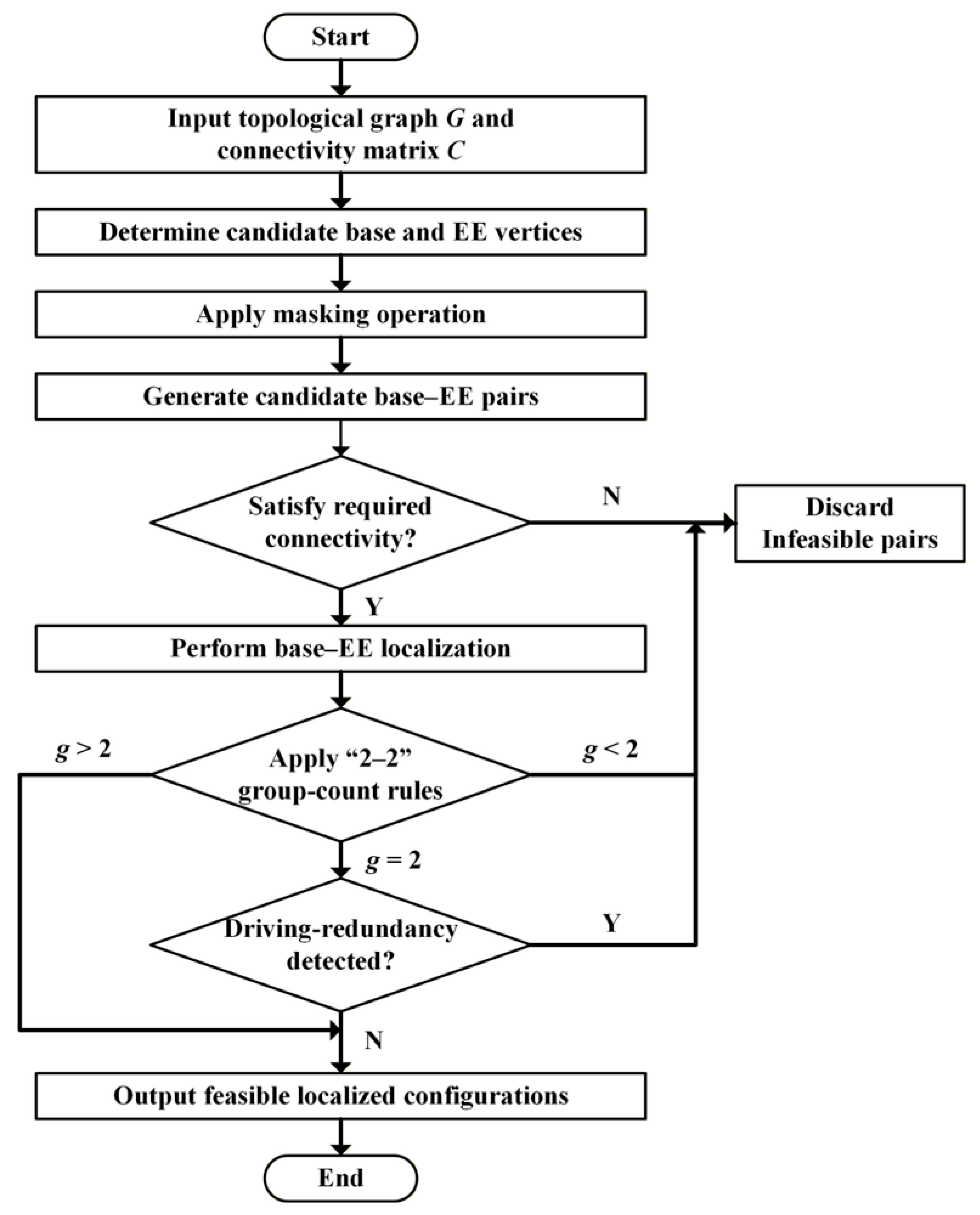
To make the full connectivity-based localization and screening process easier to follow, the overall workflow is summarized in Figure 5.
Figure 5.
Overall workflow of the connectivity-based base–EE localization and functional screening process. Here, g denotes the number of “2–2” groups in the candidate configuration.
First, the connectivity matrix C of the topological graph in Figure 3a is calculated, as shown in Figure 3b. This matrix provides the topological basis for subsequent base–EE localization and functional screening.
Next, the candidate base set is determined. For the topological graph in Figure 3a, one quaternary vertex and two ternary vertices and , satisfy the structural admissibility conditions and can therefore serve as candidates for the equivalent MJ vertex. Taking as an illustrative example, once the equivalent MJ vertex is fixed, the candidate base vertices are selected from the vertex-asymmetry set (VA) to avoid generating isomorphic configurations. For the topological graph in Figure 3a, the VA is
Accordingly, the candidate set of base vertices is
After the candidate base set has been identified, feasible base–EE combinations are determined according to the connectivity criterion. For planar FKCs, cut vertices and cut edges correspond structurally to the equivalent bases or EEs of decomposed subchains. Therefore, the feasible set of EE vertices should be determined in conjunction with object-oriented information. In the engineering case considered in this study, the mine scaler manipulator arm is decomposed into three subchains (KC1–KC3). KC1 and KC2 are connected by a cut edge corresponding to a hydraulic actuator, and the DOF of KC1 therefore increases by one. In addition, when the MJ is equivalently transformed into a simple joint, the DOF increases by another one. Consequently, the relevant connectivity index of KC1 increases from 1 to 3. For a given base candidate , the feasible EE set is determined according to Equation (8), namely, by identifying all vertices satisfying .
Accordingly, feasible EE candidates are obtained by iterating over the base candidate set and identifying all vertices whose connectivity value with the selected base is equal to 3. Any vertex pair satisfying is regarded as a feasible base–EE combination. The corresponding statistical results are listed in Table 1.
Table 1.
Base–EE pairs satisfying the connectivity criterion .
Finally, for each feasible base–EE combination, a masking operation is applied when counting the “2–2” chains, and driving redundancy is evaluated according to rules R4.1–R4.3. As an example, for the feasible base–EE combination , where is the base and is the EE, the binary-vertex chains and correspond to two driving pairs. Since none of the detailed redundancy conditions in R4.3 is triggered, no driving redundancy is detected and the configuration is retained. In contrast, for the feasible base–EE combination , no “2–2” chain can be assigned as a hydraulic-cylinder driving pair, that is, . Therefore, this configuration is discarded.
5. Case Study and Results
In this section, the proposed connectivity-based localization and screening method was applied to an engineering case, namely, the KC1 subchain of a mine scaler manipulator arm. The engineering background, target subchain representation, candidate atlas, and final screening results are presented in sequence to demonstrate the applicability of the proposed method in a realistic design scenario. The selected KC1 subchain was used here as a representative engineering example to illustrate the proposed workflow, rather than to provide an exhaustive comparison across different mechanism types. This case also helps clarify both the applicability and the current scope of the proposed method.
5.1. Engineering Case Description
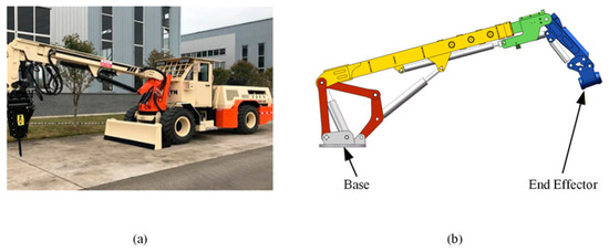
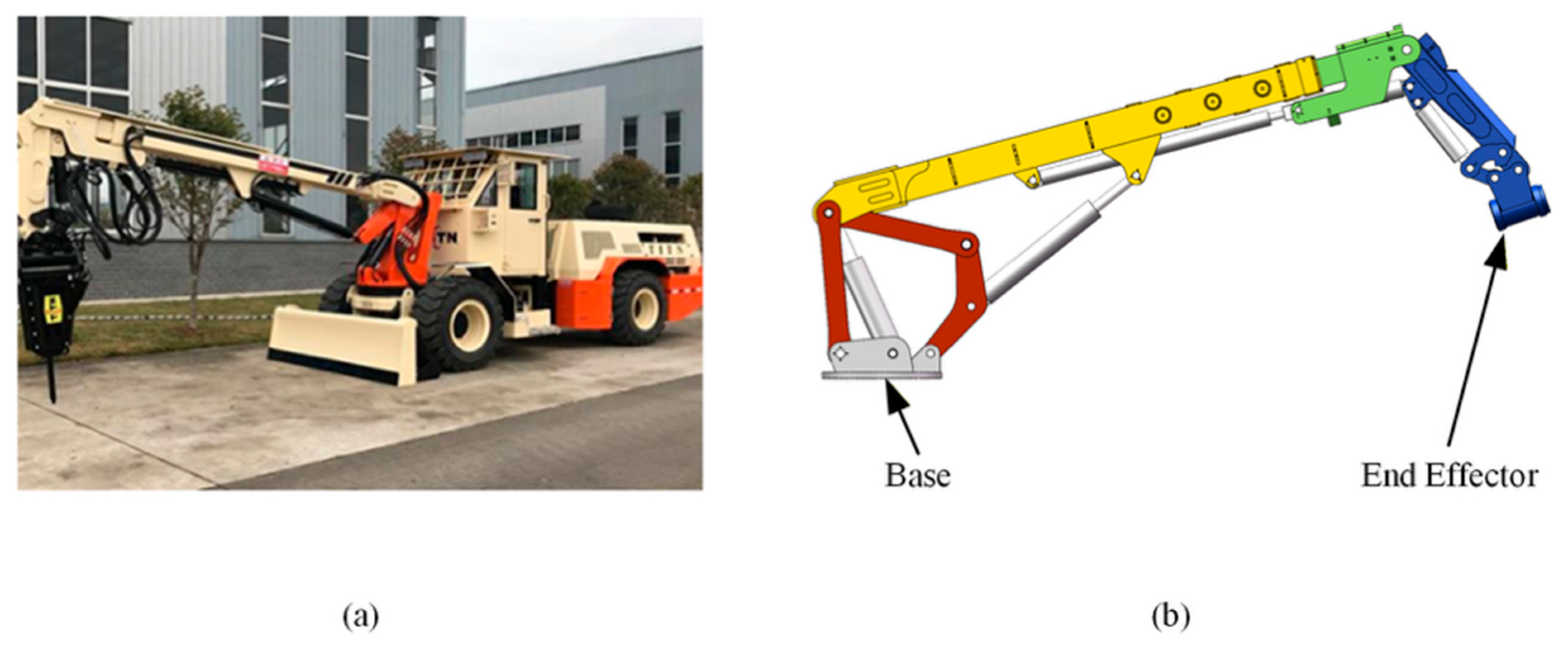
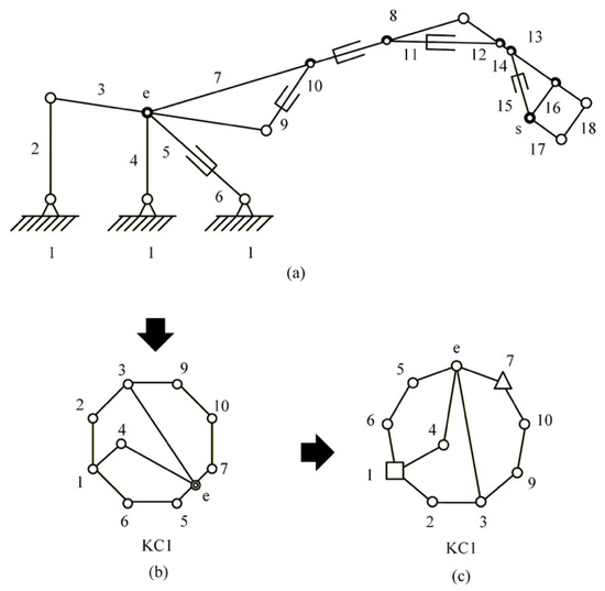
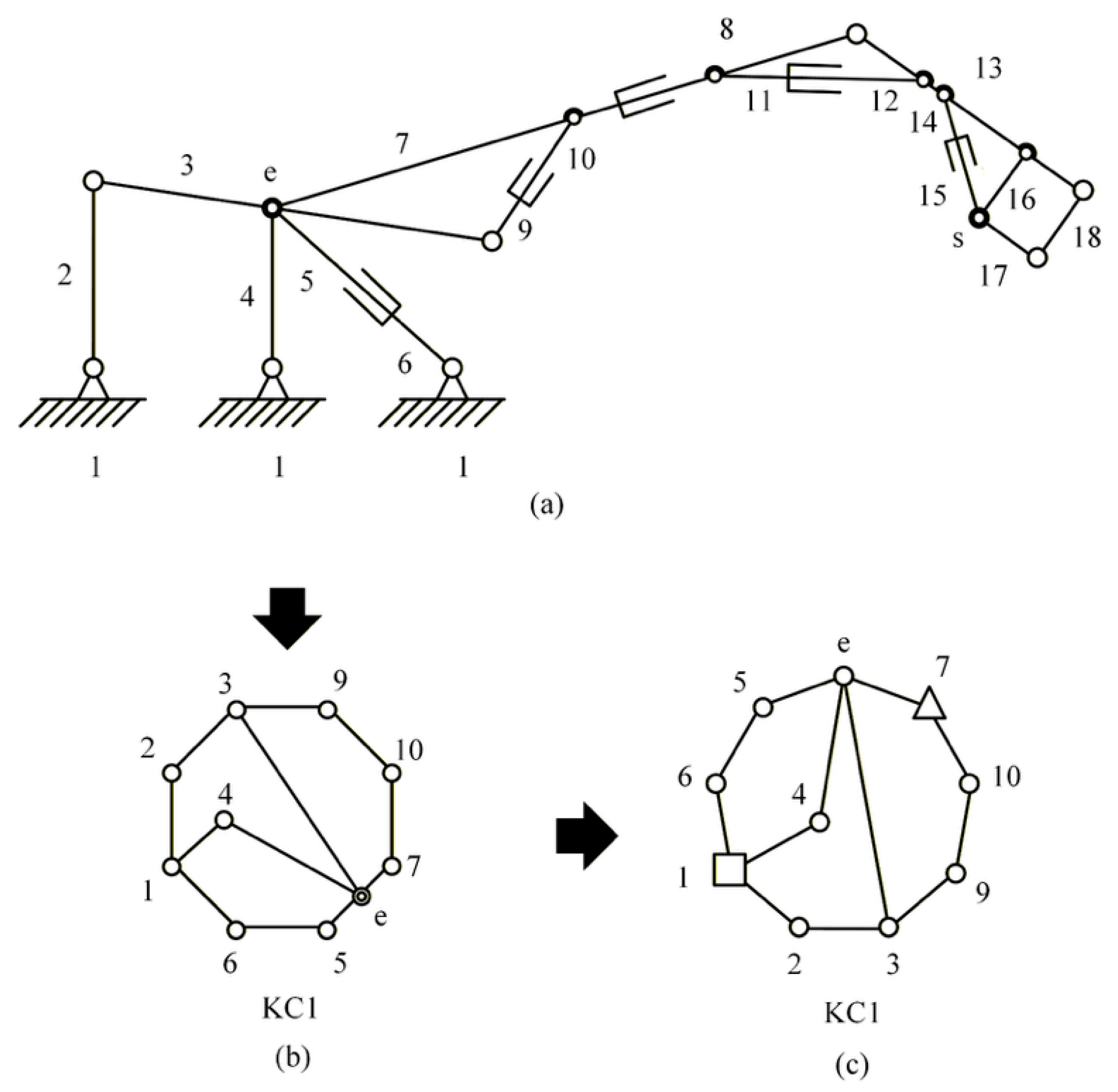
A mine scaler manipulator arm was selected as the engineering case to validate the proposed connectivity-based localization and screening method, as shown in Figure 6. Its topology was abstracted as an 18-link, 5-DOF FKC, as shown in Figure 7a. After system-level decomposition, attention focused on the KC1 subchain, which is the most topologically complex subchain in the overall structure and therefore serves as a representative case for demonstrating the proposed method. This subchain is a 9-link, 2-DOF planar KC containing one MJ, as shown in Figure 7b.
Figure 6.
Engineering background of the mine scaler manipulator arm. (a) A mine scaler vehicle. (b) Schematic model of the manipulator arm, showing the base and end effector.
Figure 7.
(a) Schematic of the mine scaler manipulator arm. (b) Topological graph of the KC1. (c) The single-joint equivalent topological graph of KC1.
For unified topological modeling and matrix-based computation, the MJ is converted into a single-joint equivalent chain using the standard equivalence treatment adopted in configuration synthesis, as shown in Figure 7c. As a result, the target subchain is represented as a 10-link, 3-DOF planar KC in its single-joint equivalent form. Unless otherwise specified, all subsequent graph representations, connectivity calculations, and functional screening procedures in this section were performed on this single-joint equivalent representation. Based on this equivalent representation, the following subsection introduces a structurally admissible candidate atlas as the input set for connectivity-based localization and screening.
5.2. Candidate Atlas for the Case Study
Connectivity-based localization is meaningful only when applied to a candidate atlas that is already structurally admissible for the design task. Therefore, before functional screening, a structurally admissible candidate atlas is generated for the target subchain using a constraint-driven synthesis strategy. The structural constraints can be summarized into four groups [24].
- (1)
- Degree-sequence and main-loop constraints: the existence of a main loop and the validity of the vertex-degree sequence are verified.
- (2)
- Task-specific adjacency constraints: key adjacency relations are imposed among binary vertices, including those involving actuator endpoints in the single-joint equivalent representation, the equivalent MJ vertex, and grouped “2–2” patterns on the main loop.
- (3)
- Exclusion rules: topologies containing rigid subchains, topologies that become rigid after assigning the MJ to a multiple-degree vertex, and undesirable local patterns such as serial “2–2–2–2” segments are discarded.
- (4)
- Isomorphism removal: isomorphism discrimination is performed on main-loop-normalized graphs, and stable identifiers are assigned to the retained candidates.
After structural filtering and isomorphism removal, 36 non-isomorphic candidate topological graphs were retained. These graphs constitute the candidate atlas used in this case study. The candidates were distributed over three link assortment arrays (LAAs), and the corresponding statistics are summarized in Table 2. The complete candidate topological graph atlas is provided in Supplementary Material S1.
Table 2.
Distribution of candidate topological graphs.
5.3. Connectivity-Based Localization and Screening Results
According to the methods described in Section 3 and Section 4, connectivity-based localization and functional screening were carried out automatically for all candidate topological graphs in the KC1 atlas. For each candidate, the connectivity matrix is first calculated, after which the candidate base set is determined. Feasible base–EE combinations are then identified using the criterion . The retained combinations are further subjected to masking-based counting of “2–2” chains and driving-redundancy detection.
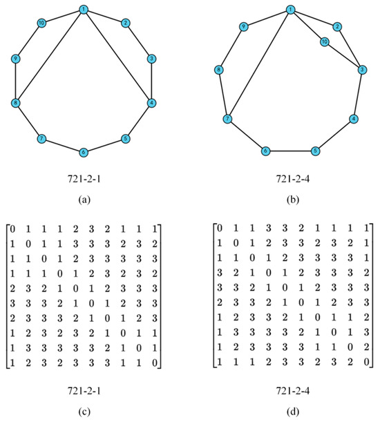
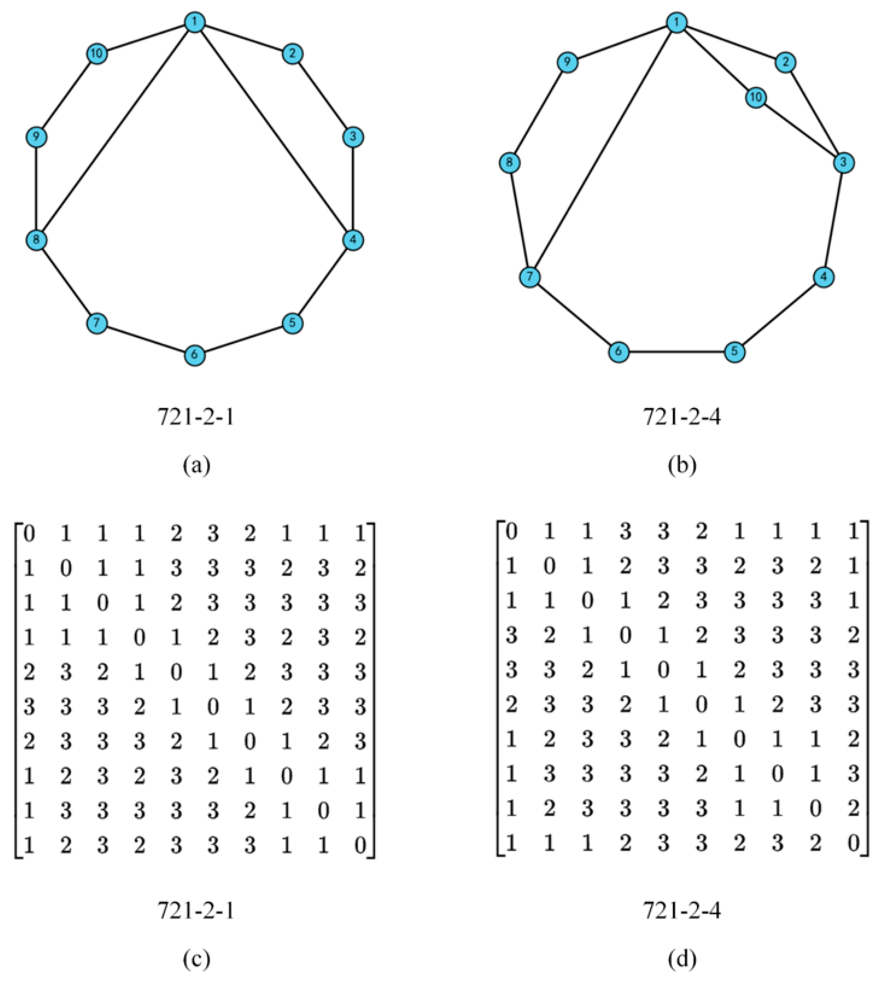
The topological graphs “721-2-1” and “721-2-4” are taken as representative examples, and their connectivity matrices are shown in Figure 8c,d, respectively. Here, “721” denotes the LAA, “2” denotes the number of multiple edges in the corresponding contracted graph, and “4” denotes the index of the topological graph within the corresponding LAA category. For “721-2-1”, none of the multiple-degree vertices satisfied the admissibility requirement for equivalent multiple-joint assignment, and the topology was therefore discarded. In contrast, for “721-2-4”, only can serve as the equivalent multiple-joint vertex, and the corresponding candidate base set is:
Figure 8.
(a) Topological graph of 721-2-1; (b) topological graph of 721-2-4; (c) the connectivity matrix of 721-2-1; (d) the connectivity matrix of 721-2-4.
For this graph, multiple base–EE pairs satisfied the connectivity criterion and were therefore retained for further verification. For each feasible pair, masking was applied before counting the number of “2–2” chains, and driving redundancy was evaluated according to rules R4.1–R4.3. For example, for the pair , masking yielded the global vertex-degree sequence “433223322-2”, which contained two “2–2” chains, i.e., . Since neither R4.3.1 nor R4.3.2 was triggered, this pair was judged non-redundant and retained. In contrast, for the pair , masking yielded the global vertex-degree sequence “423232332-2”, for which . This pair was therefore excluded.
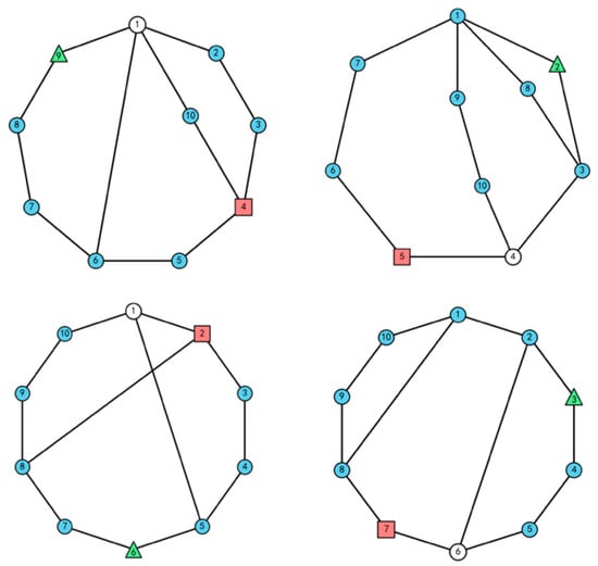
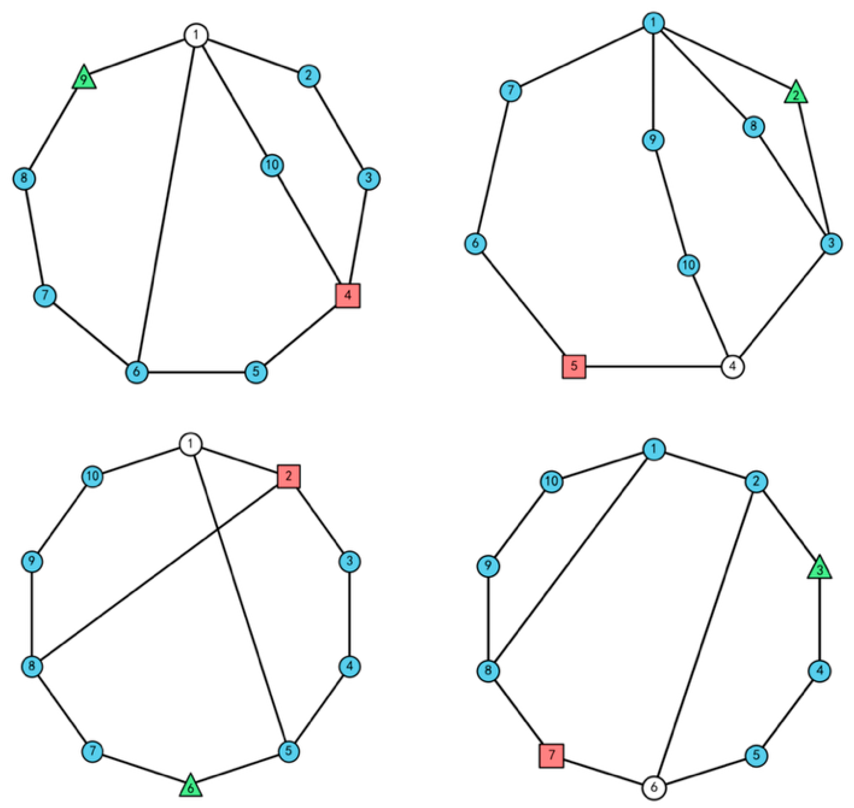
Using the above procedure, a final set of 249 feasible configurations was obtained, as summarized in Table 3. The retained configurations were plotted using a unified graphical convention, in which bases are marked by squares, EEs by triangles, and equivalent MJs by hollow vertices. Representative feasible configurations are shown in Figure 9, and the complete atlas of feasible configurations is provided in Supplementary Material S2.
Table 3.
The synthesis result of feasible configurations.
Figure 9.
Excerpt of the feasible configurations. Bases are marked by squares, EEs by triangles, and equivalent MJs by hollow vertices.
From the engineering perspective, these 249 retained configurations should not be interpreted merely as a reduced number of candidates, but as a complete feasible design pool under the prescribed structural and functional constraints considered in this study. In traditional manipulator-arm design, configuration selection often relies heavily on engineering experience, and it is usually difficult to determine whether the selected scheme is close to the best one or whether other feasible topologies have been overlooked. In contrast, the present workflow identifies all topologically feasible configurations that satisfy the given screening requirements at the topological level. Therefore, the final retained set provides a bounded and explicit candidate space for subsequent scheme selection, allowing for later dimensional synthesis and detailed engineering evaluation to be carried out within the complete feasible topological space defined by the current constraints.
6. Discussion
The proposed method was developed for the application-oriented configuration synthesis of planar multi-loop KCs, where large candidate atlases must be screened efficiently under prescribed functional requirements. In the preceding sections, the method has been presented through loop-constrained connectivity calculation, base–EE localization, and rule-based functional screening, and its applicability has been demonstrated through the KC1 case study of a mine scaler manipulator arm. In this section, the computational characteristics of the connectivity calculation, comparative verification on a face-shovel excavator manipulator arm case, the flexibility and applicability of the method, and the engineering interpretation of the retained configurations are discussed.
6.1. Computational Characteristics of the Proposed Connectivity Calculation
A major advantage of the proposed method is that the connectivity calculation is explicitly organized around the main loop and the independent loops. Under this representation, loop-constraint information and shortest-path information are incorporated into a unified matrix-based framework through the construction of the minimum mobility matrix Q, the minimum distance matrix D, and the resulting connectivity matrix C. This organization makes the overall procedure clear and well-suited to planar multi-loop topological graphs generated in candidate atlases.
Compared with representative connectivity calculation methods based on more general shortest-path treatments, the proposed method is better matched to sparse planar multi-loop graphs whose loop structure is already available from candidate-atlas generation. In particular, shortest-path evaluation is carried out by all-source BFS on the Booleanized simple graph, yielding a complexity of , where n and m denote the numbers of vertices and edges, respectively, rather than the complexity associated with conventional all-pairs shortest-path computation [22]. In addition, no virtual-edge construction is required, and only the minimum mobility associated with each vertex pair is retained in the construction of Q. These features help reduce computational burden while preserving clear physical meaning and ease of implementation.
6.2. Comparative Verification on the Face-Shovel Excavator Manipulator Arm Case
To further examine the applicability of the proposed workflow beyond the primary mine-scaler-oriented case, a comparative verification was carried out using the face-shovel excavator manipulator arm case reported in [23]. Since the synthesis results are highly sensitive to the imposed structural and functional constraints, the same structural and functional constraints as those adopted in [23] were used here to ensure a controlled comparison.
The quantitative comparison is summarized in Table 4. In the workflow of Huang et al. [23], all ordered base–EE assignments were first enumerated for each non-isomorphic topology. In contrast, in the present workflow, only base–EE pairs satisfying were retained, and symmetry-equivalent base assignments were further removed using the vertex symmetry set (VS), which denotes the set of topologically symmetric vertices in each topology. As a result, the number of candidate assignments entering the downstream isomorphism-identification stage was markedly reduced from 258,984 to 1166.
Table 4.
Quantitative comparison between the workflow of Huang et al. and the present workflow for the face-shovel excavator case.
6.3. Flexibility and Applicability of the Proposed Method
The proposed workflow is rule-driven and can incorporate additional application preferences without changing the core connectivity calculation. For example, the feasible sets of base and EE vertices can be further restricted according to design requirements, and additional preferences can be imposed on equivalent multiple-joint assignment or actuator placement relative to specific loops. Therefore, different synthesis outcomes can be obtained by revising application-specific constraints and screening rules, while keeping the core loop-constrained connectivity calculation unchanged.
This flexibility makes the proposed method suitable not only for the present case study but also for other engineering manipulators with planar multi-loop topologies represented as topological graphs. For planar NKFCs, the method can be applied directly. For planar FKCs, however, the present framework is not applied directly at the full-system level, but only to decomposed non-fractionated subchains after system-level decomposition. Therefore, the proposed framework provides a transferable basis for connectivity-based localization and screening for different engineering requirements.
6.4. Engineering Interpretation of the Retained Configurations
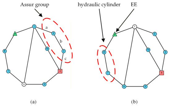
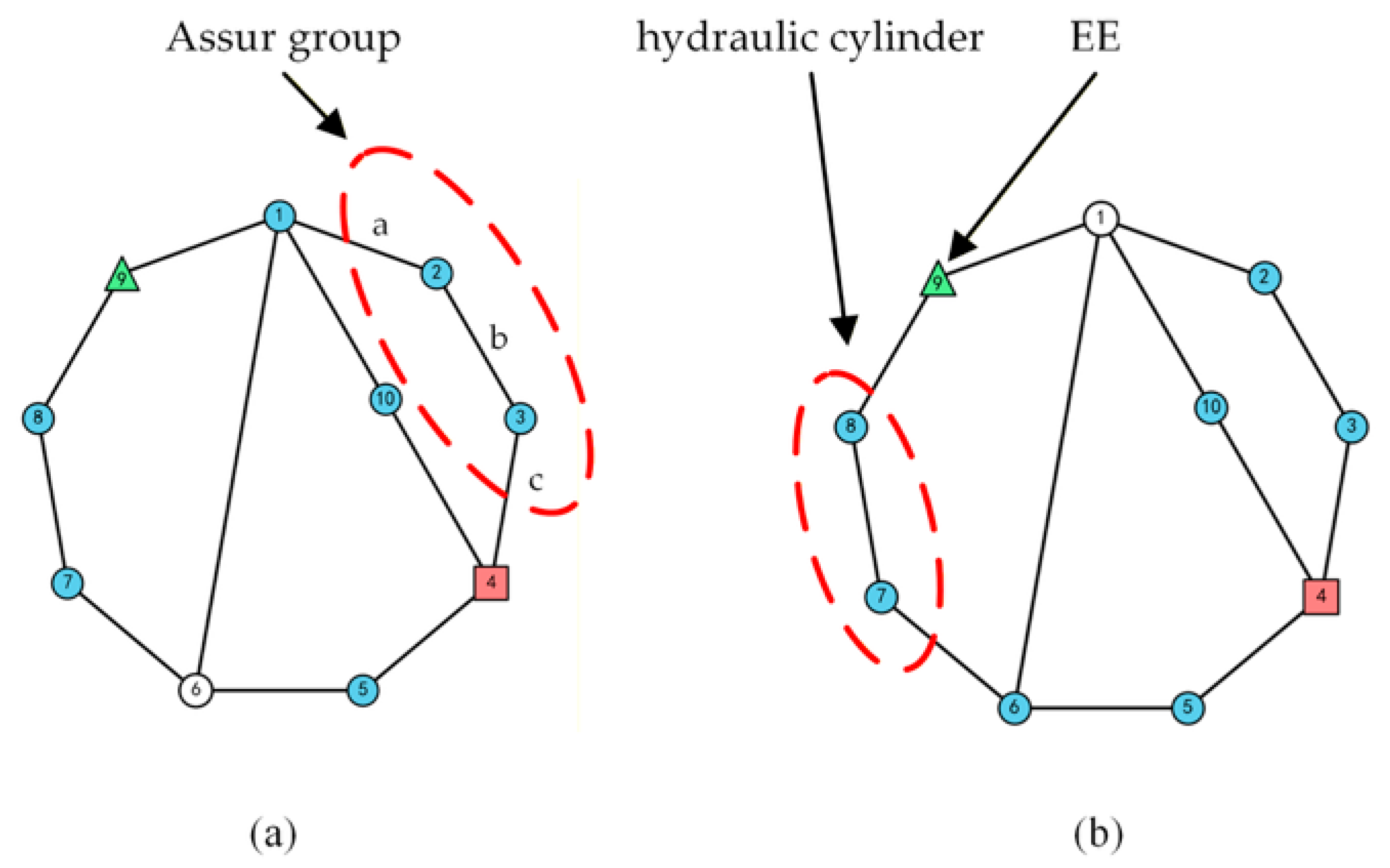
Among the retained configurations, some may contain a first-class Assur group, as illustrated in Figure 10a. Such configurations imply a certain degree of link redundancy and are therefore considered less desirable for practical application. Whenever other feasible alternatives are available, they should be avoided.
Figure 10.
Representative retained configurations for engineering interpretation: (a) a configuration containing a first-class Assur group formed by links 2 and 3 and joints a, b, and c; (b) a directly connected configuration with a hydraulic cylinder connected to the EE.
For the remaining configurations, an engineering-oriented classification can be introduced according to whether a hydraulic cylinder is directly connected to the EE. On this basis, the retained configurations can be divided into directly connected and non-directly connected types. For the mine scaler manipulator design considered in this study, the directly connected configurations are regarded as the preferred category, as exemplified in Figure 10b, because they generally provide a better workspace and exhibit closer similarity to existing industrial designs. This classification is intended to support the formation of a practical shortlist from the retained configurations. The final scheme selection, however, still requires subsequent dimensional optimization and performance evaluation.
7. Conclusions
A loop-constrained connectivity calculation and a connectivity-based localization and screening workflow have been presented for planar multi-loop KCs. Starting from a structurally admissible, non-isomorphic candidate topological graph atlas, the proposed method establishes a connectivity matrix for topological base–EE localization, followed by rule-based functional screening under application-oriented requirements. The present framework is directly formulated for planar NFKCs. For planar FKCs, the current workflow still relies on prior decomposition into non-fractionated subchains, rather than direct full-system treatment. The method has been validated on the 10-link, 3-DOF single-joint equivalent of the KC1 subchain of a mine scaler manipulator arm, yielding 249 feasible configurations. In addition, a comparative verification was carried out on a face-shovel excavator manipulator arm case to further examine the applicability of the proposed workflow and its effect on reducing downstream isomorphism-identification workload.
The main conclusions are summarized as follows:
- (1)
- A loop-constrained connectivity calculation method was established for planar multi-loop KCs. By combining loop-based minimum mobility evaluation with shortest-path information, the resulting connectivity matrix provides a clear and practical basis for topological analysis.
- (2)
- Connectivity-based base–EE localization and functional screening were integrated into a unified workflow. On this basis, structurally admissible candidate graphs can be transformed into functionally feasible configurations under explicit screening criteria.
- (3)
- The proposed method is suitable for the batch processing of candidate atlases and can effectively support engineering-oriented configuration synthesis. In the present mine scaler case, the candidate atlas was reduced to a feasible configuration set through connectivity-based localization, masking, redundancy detection, and rule-based screening. In the face-shovel excavator manipulator arm case, the proposed workflow was further shown to substantially reduce the candidate assignments entering the downstream isomorphism-identification stage.
- (4)
- The proposed framework remains flexible at the rule level. Different engineering preferences can be incorporated by revising application-specific constraints and screening rules, while the core connectivity calculation remains unchanged.
Future work will focus on developing a connectivity calculation method directly applicable to planar FKCs, so that connectivity-based localization and functional screening can be performed at the system level rather than only at the decomposed subchain level.
Supplementary Materials
The following supporting information can be downloaded at: https://www.mdpi.com/article/10.3390/machines14040455/s1, Supplementary Material S1. Complete atlas of candidate topological graphs. Supplementary Material S2. Complete atlas of feasible configurations.
Author Contributions
X.L.: methodology, software, validation, formal analysis, investigation, data curation, visualization, writing—original draft, writing—review and editing. H.D.: conceptualization, supervision, writing—review and editing. All authors have read and agreed to the published version of the manuscript.
Funding
This research received no external funding.
Institutional Review Board Statement
Not applicable.
Informed Consent Statement
Not applicable.
Data Availability Statement
The original contributions presented in this study are included in the Supplementary Materials. Further inquiries can be directed to the corresponding author.
Conflicts of Interest
The authors declare no conflicts of interest.
Nomenclature and Abbreviations
| Abbreviations | |
| NFKC | Non-fractionated kinematic chain |
| FKC | Fractionated kinematic chain |
| EE | End effector |
| KC | Kinematic chain |
| base–EE | Base and end effector |
| DOF | Degree of freedom |
| MJ | Multiple joint |
| BFS | Breadth-first search |
| VA | The vertex-asymmetry set |
| LAA | Link assortment array |
| VS | The vertex symmetry set |
| Symbols | |
| G | Topological graph of a planar kinematic chain |
| V | Vertex set of the topological graph |
| E | Edge set of the topological graph |
| N | Number of links |
| M | Degree of freedom of the planar kinematic chain |
| L | Number of independent loops |
| A | Adjacency matrix |
| Ab | Boolean adjacency matrix |
| Gb | Booleanized simple unweighted graph |
| Q | Minimum mobility matrix |
| D | Minimum distance matrix |
| C | Connectivity matrix |
| Msub | Degree of freedom of a subchain |
| dist(i,j) | Unweighted shortest-path length between vertices i and j |
| Sij | Set of subchains containing both vertices i and j |
| VB | Candidate set of base vertices |
| VE | Candidate set of end-effector vertices |
| g | Number of “2–2” chains after masking |
References
- Al-Dweiri, A.F.; Dweiri, F.T.; Ashour, O.M. A novice-centered decision-support system for type synthesis of function-generation mechanisms. Mech. Mach. Theory 2010, 45, 1252–1268. [Google Scholar] [CrossRef] [Scilit]
- Yan, H.S.; Hung, C.C. Identifying and counting the number of mechanisms from kinematic chains subject to design constraints. ASME J. Mech. Des. 2006, 128, 1177–1182. [Google Scholar] [CrossRef] [Scilit]
- Hung, C.C.; Yan, H.S.; Pennock, G.R. A procedure to count the number of planar mechanisms subject to design constraints from kinematic chains. Mech. Mach. Theory 2008, 43, 676–694. [Google Scholar] [CrossRef] [Scilit]
- Naik, S.V.; Saxena, A.; Rai, A.K.; Reddy, B.V.S.N. How to choose from a synthesized set of path-generating mechanisms. ASME J. Mech. Des. 2011, 133, 091009. [Google Scholar] [CrossRef] [Scilit]
- Shoham, M.; Roth, B. Connectivity in open and closed loop robotic mechanisms. Mech. Mach. Theory 1997, 32, 279–293. [Google Scholar] [CrossRef] [Scilit]
- Mruthyunjaya, T.S. Kinematic structure of mechanisms revisited. Mech. Mach. Theory 2003, 38, 279–320. [Google Scholar] [CrossRef] [Scilit]
- Simoni, R.; Carboni, A.P.; Simas, H.; Martins, D. Enumeration of kinematic chains and mechanisms review. In Proceedings of the 13th World Congress in Mechanism and Machine Science, Guanajuato, México, 19–25 June 2011. [Google Scholar]
- Yan, H.S.; Chiu, Y.T. On the number synthesis of kinematic chains. Mech. Mach. Theory 2015, 89, 128–144. [Google Scholar] [CrossRef] [Scilit]
- Tsai, L.W. Mechanism Design: Enumeration of Kinematic Structures According to Function; CRC Press: Boca Raton, FL, USA, 2000. [Google Scholar]
- Nie, S.H.; Liao, A.H.; Qiu, A.H.; Gong, S.G. Addition method with 2 links and 3 pairs of type synthesis to planar closed kinematic chains. Mech. Mach. Theory 2012, 58, 179–191. [Google Scholar] [CrossRef] [Scilit]
- Chiu, Y.T.; Yan, H.S. An algorithm for the automatic sketching of generalized kinematic chains. In Proceedings of the 14th IFToMM World Congress, Taipei, Taiwan, 25–30 October 2015. [Google Scholar]
- Pucheta, M.A.; Ulrich, N.E.; Cardona, A. Combined graph layout algorithms for automated sketching of kinematic chains. In Proceedings of the ASME IDETC and CIEC, Chicago, IL, USA, 12–15 August 2012. [Google Scholar]
- Pucheta, M.A.; Ulrich, N.E.; Cardona, A. Automated sketching of non-fractionated kinematic chains. Mech. Mach. Theory 2013, 68, 67–82. [Google Scholar] [CrossRef] [Scilit]
- Bedi, G.S.; Sanyal, S. Loop based algorithm for automatic sketching of planar kinematic chains. In Proceedings of the 1st International and 16th National Conference on Machines and Mechanisms, Roorkee, India, 18–20 December 2013. [Google Scholar]
- Ding, H.F.; Huang, P.; Yang, W.J.; Kecskemethy, A. Automatic generation of the complete set of planar kinematic chains with up to six independent loops and up to 19 links. Mech. Mach. Theory 2016, 96, 75–93. [Google Scholar] [CrossRef] [Scilit]
- Sun, L.; Ye, Z.Z.; Cui, R.J.; Huang, X.W.; Wu, C.Y. Eliminating isomorphism identification method for synthesizing nonfractionated kinematic chains based on graph similarity. Mech. Mach. Theory 2022, 167, 104500. [Google Scholar] [CrossRef] [Scilit]
- Tischler, C.R.; Samuel, A.E.; Hunt, K.H. Kinematic chains for robot hands: Part 2 kinematic constraints, classification, connectivity and actuation. Mech. Mach. Theory 1995, 30, 1217–1239. [Google Scholar] [CrossRef] [Scilit]
- Tischler, C.R.; Samuel, A.E.; Hunt, K.H. Selecting multi-freedom multi-loop kinematic chains to suit a given task. Mech. Mach. Theory 2001, 36, 925–938. [Google Scholar] [CrossRef] [Scilit]
- Belfiore, N.P.; Di Benedetto, A. Connectivity and redundancy in spatial robots. Int. J. Robot Res. 2000, 19, 1245–1261. [Google Scholar] [CrossRef] [Scilit]
- Liberati, A.; Belfiore, N.P. A method for the identification of the connectivity in multi-loop kinematic chains: Analysis of chains with total and partial mobility. Mech. Mach. Theory 2006, 41, 1443–1466. [Google Scholar] [CrossRef] [Scilit]
- Martins, D.; Carboni, A.P. Variety and connectivity in kinematic chains. Mech. Mach. Theory 2008, 43, 1236–1252. [Google Scholar] [CrossRef] [Scilit]
- Yang, W.J.; Ding, H.F.; Kecskemethy, A. Algorithm for computing the connectivity in planar kinematic chains and its application. Proc. IMechE Part C J. Mech. Eng. Sci. 2021, 235, 4988–4997. [Google Scholar] [CrossRef] [Scilit]
- Huang, P.; Ding, H.F.; Yang, W.J.; Xu, G.Y. Connectivity calculation-based automatic synthesis of planar multi-loop mechanisms. ASME J. Mech. Robot. 2021, 13, 041004. [Google Scholar] [CrossRef] [Scilit]
- Li, X.X.; Ding, J.S.; Ding, H.F. Automatic synthesis of planar multi-loop fractionated kinematic chains with multiple joints: Topological graph atlas and a mine scaler manipulator case study. Machines 2026, 14, 129. [Google Scholar] [CrossRef] [Scilit]

Disclaimer/Publisher’s Note: The statements, opinions and data contained in all publications are solely those of the individual author(s) and contributor(s) and not of MDPI and/or the editor(s). MDPI and/or the editor(s) disclaim responsibility for any injury to people or property resulting from any ideas, methods, instructions or products referred to in the content. |
© 2026 by the authors. Licensee MDPI, Basel, Switzerland. This article is an open access article distributed under the terms and conditions of the Creative Commons Attribution (CC BY) license.