


Abstract
To investigate the non-smooth behaviour of cage-less ball bearings with localised functional grooves, this article first designs temperature-varying comparative experiments and rolling element discrete performance test protocols. Subsequently, it analyses the principles of heat generation, transmission, and exchange within ball bearings, establishing a mathematical model for bearing thermal displacement using a dynamic model. This is followed by an analysis of rolling element discrete conditions. Finally, based on experimental results, a comparative analysis of ball bearing temperature variations under combined multi-variable loading conditions is conducted. By altering radial load, axial load, and rotational speed to measure bearing friction torque under different operating conditions, the suitability of bearing operating conditions is analysed, evaluated, and optimised.
1. Introduction
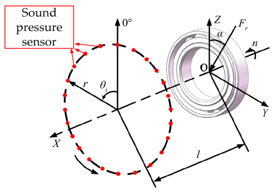
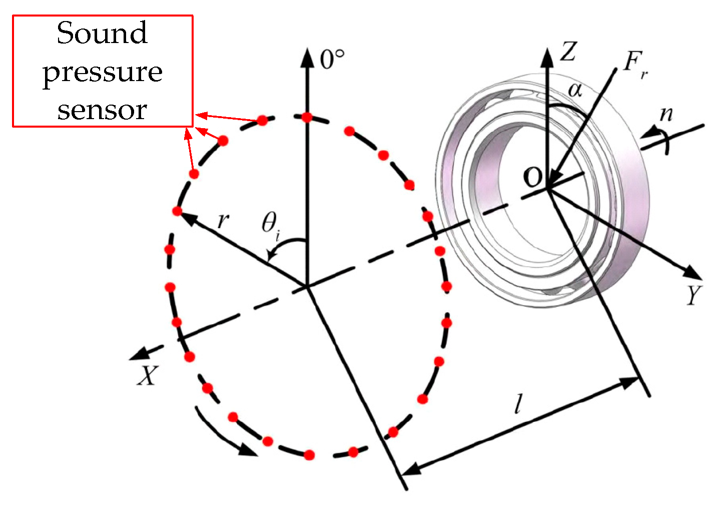
Observing and characterizing the non-smooth behavior of rolling bearings through experiments is one of the important approaches to studying ball bearing kinematics. Currently, the main methods for characterizing bearing non-smooth behavior can be broadly divided into two categories: indirect characterization and direct measurement, as shown in Figure 1.
Figure 1.
Direct measurement experimental scheme utilizing radiated noise sound pressure level to detect whether rolling elements collide with the cage.
Indirect characterization involves measuring the overall motion performance parameters of the bearing to analyze the non-smooth behavior patterns of the rolling elements. For example, acoustic, optical, electrical, and vibration signals can be collected to evaluate the rolling elements. Researchers such as Yan [1] from Hebei University of Science and Technology improved an existing bearing vibration testing machine by adding a sound pressure sensor to measure the radiated noise sound pressure level of the bearing. This approach characterized the relationship between the non-smooth collision behavior of the rolling elements with the cage and the variation in sound pressure level.
Wang [2] performed flexibility modifications on the test rig after considering multi-directional external excitation forms, enabling the measured results to characterize the service life of rolling elements affected by vibration under actual operating conditions such as combined loads. Wen [3] characterized the non-smooth behavior of rolling elements caused by unstable cage motion by measuring and analyzing the variation characteristics of eddy current signals. Wei [4] collected relevant parameters through vibration experiments and, by integrating the underlying abnormal frequency components within a visualization interface platform and performing spectral calculations, characterized in real time the abnormal operating frequencies of the rolling elements caused by bearing faults, thereby enabling timely decision-making. To minimize experimental errors, Chi [5] proposed a fault diagnosis method based on transfer learning. An LSTM-RNN transfer model was trained using source domain samples and a small number of target domain samples, and based on this transfer model, predicted target domain samples were generated to assist in diagnosis. The effectiveness of the transfer learning-based fault diagnosis method under different operating conditions and different structural parameters was verified, resulting in higher accuracy of rolling element data obtained from subsequent analysis. Tian [6] sought to more precisely characterize the non-smooth behavior in operation arising from heat generation between the rolling elements and raceways; to this end, they replaced the traditional loading device with a magnetorheological fluid dynamic loading system, which can simulate in real time the thermally induced preload forces resulting from bearing heating.
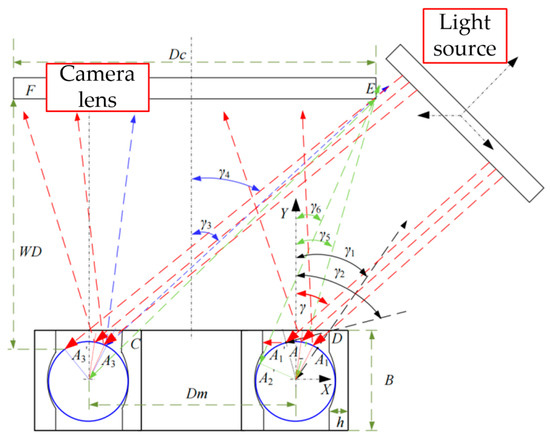
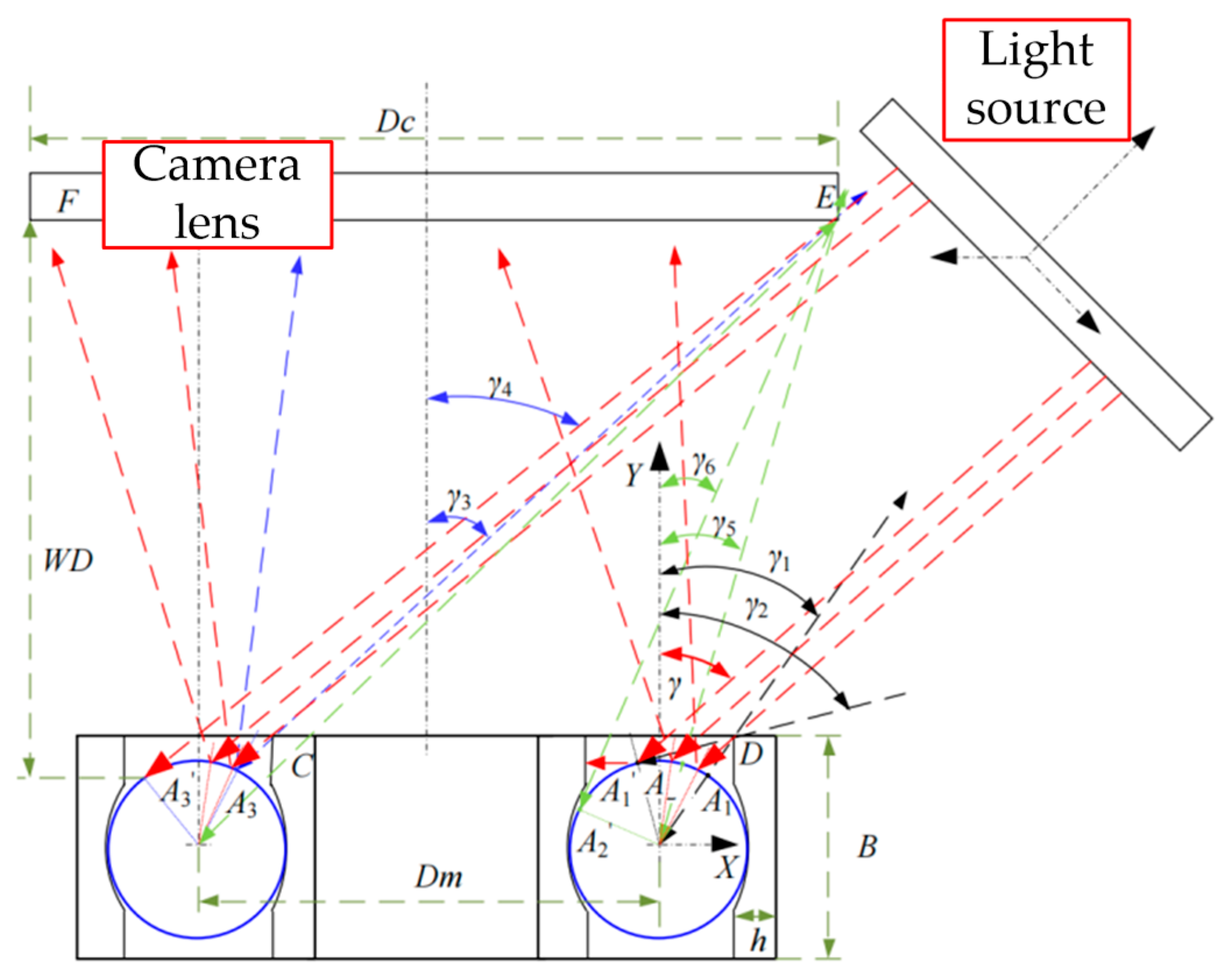
Pan [7] focused on the dynamic characteristics between rolling elements and raceways with different topographies under high-speed operating conditions. They designed a novel bearing dynamic characteristics test rig, providing valuable insights for subsequent performance testing of high-speed bearings. Han [8] conducted experiments on the radial-to-axial stiffness gradient ratio and, by combining the variation curves and amplitudes of the contact angle between the rolling elements and raceways, characterized the time-varying stiffness of the rolling elements and the patterns of vibration amplitude changes under combined loads. Regarding the direct experimental measurement of non-smooth behavior in rolling elements, approaches are broadly categorized into two main types: optical calibration (as shown in Figure 2) and electromagnetic measurement.
Figure 2.
High-speed photography captures the principle of reflective points of rolling elements.
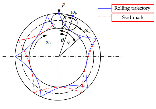
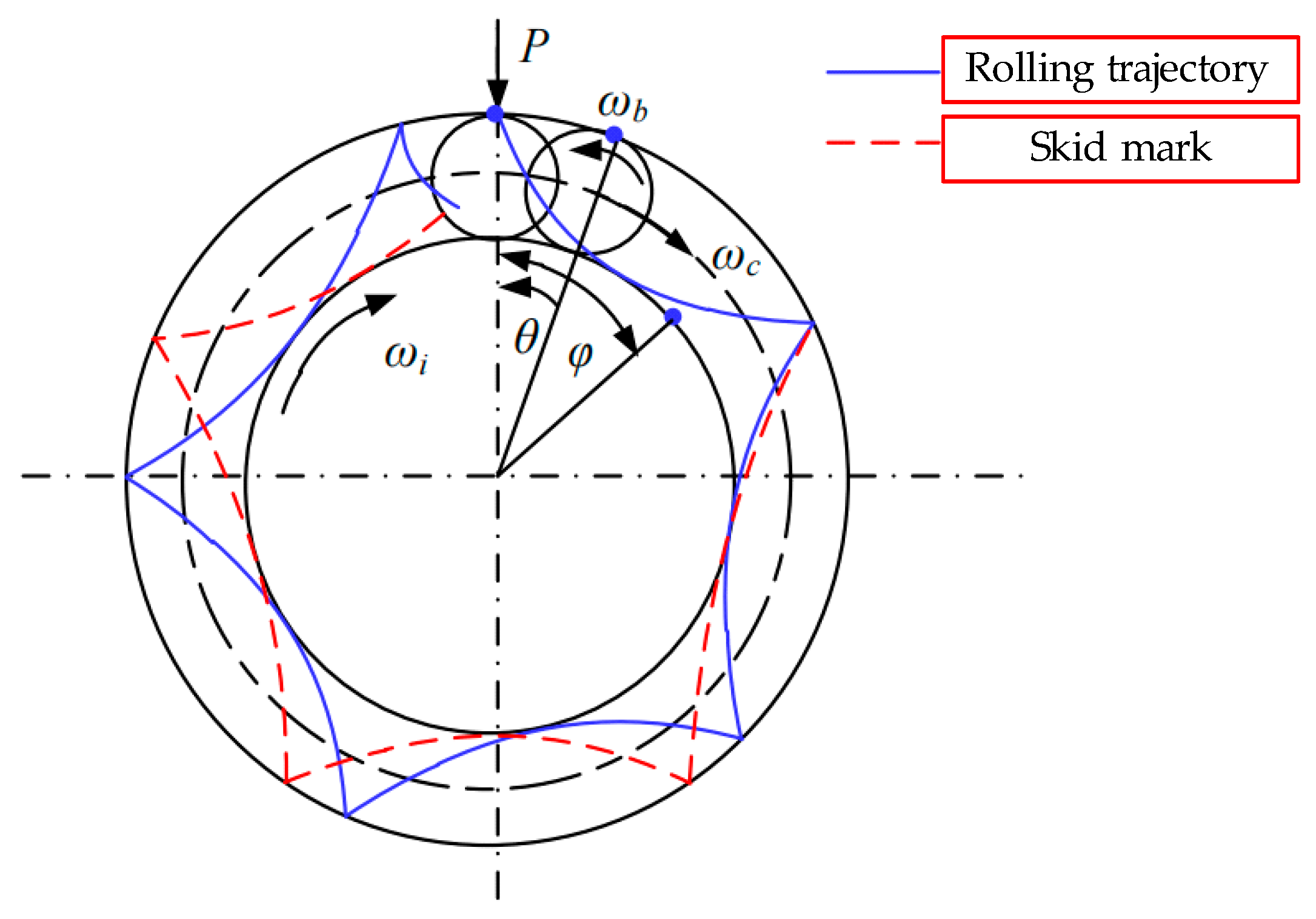
A representative study on optical calibration is by Wu [9], who processed the reflected points at the center of the bearing rolling elements captured by a high-speed camera multiple times to obtain the center coordinates of the rolling element, providing data for subsequent calculations of the angular velocity of the revolution. Ariyoshi [10] employed one-dimensional calibration to map the trajectory curve of the bearing rolling element during pure rolling and then conducted one-dimensional calibration again on the same rolling element after a certain period of bearing rotation. This comparison revealed various non-smooth behaviors during the operation of the rolling element, as shown in Figure 3.
Figure 3.
One-dimensional calibration principle of Fractal motion behavior of rolling elements.
Boness [11] determined the rotation angle and pose of the rolling elements by fitting the trajectories formed by light spots at set imaging time intervals, thereby generating continuous sequences of dynamically changing images to identify non-smooth behavior of the rolling elements. Gao [12] taking into account the independence of non-smooth behavior exhibited by each rolling element in the bearing, proposed an improved one-dimensional calibration measurement method. This approach enables real-time regression of the calibrated pose information of the rolling elements, thereby reducing dynamic errors during the calibration process.
In terms of measuring the non-smooth behavior of rolling elements through electromagnetism, many scholars have used this method to observe the mutual motion between the rolling elements and the cage [13,14,15,16]. However, with further research, it was found that this method requires the rolling elements to be processed using magnetoelectric induction, which leads to significant drift in the received sensor signals. Although the subsequent use of eddy current technology improved this issue, the modeling and decoupling of signals during post-processing were hindered by lubricating oil and temperature. Therefore, only a small number of scholars conducted research in this area in the early stages [17,18,19,20]. Representative works include Hirano [21], who magnetized the rolling elements and compared the induced current signals generated each time the magnetic flux lines were cut against theoretical dynamic patterns, thereby analyzing and identifying non-smooth behavior of the rolling elements caused by factors such as skidding and differential sliding. Kawakita [22], aiming to obtain more precise excitation signals, installed three sets of Hall elements inside the cage to position them closer to the rolling elements and reduce measurement errors. Simultaneously, the three Hall elements enabled the acquisition of excitations in three directions, achieving dynamic measurement of the three-degree-of-freedom non-smooth behavior of the rolling elements.
Damage to the bearing surface can lead to a loss of dimensional accuracy of the bearing, cause certain deformations on the working surface, increase the instability of the rolling elements’ movement within the raceway, result in slipping of the rolling elements, enhance the non-smooth behavior of the rolling elements, and, in severe cases, cause the entire bearing system to fail [23,24,25,26]. However, bearing surface damage is difficult to measure directly, necessitating the modeling of the bearing raceway at different scales [27,28].
As the diversity of bearing operating settings and specialized service conditions expands, current bearing constructions are inadequate in adapting to and fulfilling the escalating demands. Creating innovative bearings that modify the contact arrangement between the raceway and rolling parts to diminish the incidence of non-linear motion behaviour has become a crucial element of bearing research and development [13].
Qin [29], affiliated with the same institution as Hou, optimized bearing raceway structures by modifying the rolling element’s radius of gyration. This minimized collisions among neighboring rolling elements, thereby reducing the incidence of non-linear motion behaviour. Zmarzly [16] aimed to optimize the friction of rolling elements and their motion states. They conducted experimental research by gradually modifying the curvature radius of bearing raceways and the dimensions of rolling elements, examining enhancements in non-linear motion behaviour following optimization. This method offers design concepts and research methodologies for specialized bearings adapted to certain operating circumstances.
Cage-less ball bearings have increasingly garnered the interest of researchers due to their superior suitability compared to conventional bearings for application as protective bearings in active magnetic bearings (AMBs). Researchers have therefore examined their performance attributes and the non-linear motion behavior seen upon the removal of the cage, differentiating them from traditional bearings. Helfert [30] utilized high-speed photography and image recognition techniques to calibrate the positions of rolling elements and inner rings at a rotor frequency of 150 Hz, in order to examine the correlation between rolling element revolution and inner ring stability in non-linear motion behaviour. It was found that bearing instability occurs due to the rolling element’s revolution stabilization time being three times greater than that of the inner ring. The R&D team of Japan Kūyu bearings has developed a uniquely shaped raceway ball bearing that operates without a cage, yet performs comparably to one [31]. The designers integrated externally recessed deceleration pits into the inner raceway of the bearing’s outer ring; as the balls enter these pits, they inherently decelerate, thus augmenting the distance between them and the preceding ball. Subsequently, they executed a sequence of performance evaluations under completely unloaded conditions. The test findings demonstrated that the new bearing necessitates far less torsional torque than traditional ball bearings and has relatively high-temperature endurance; nevertheless, no comprehensive explanation or justification of the underlying mechanism was offered.
Through analyzing the aforementioned literature, it can be seen that although direct measurement of the non-smooth behavior of rolling elements can visually exhibit dynamic behavior, it has gradually been replaced by indirect characterization experimental methods due to technological advancements and the demand for measurement accuracy. However, while indirect characterization has improved the measurement accuracy of bearing-related parameters, it is not as precise as direct measurement methods when it comes to quantitatively describing the motion posture of rolling elements. Currently, scholars do not apply both direct measurement and indirect characterization in their research on bearing non-smooth behavior. Therefore, it is essential to utilize the discrete information of adjacent rolling elements obtained through direct measurement to assist in the indirect characterization of parameters such as vibration, heat generation, and frictional torque when conducting research on bearing non-smooth behavior.
2. Materials and Methods
This section applies principles of physics and thermodynamics to analyze the fundamentals of the dynamic performance experiment and to design the non-smooth behavior experiment for bearings with localized functional grooves. By incorporating the interaction models of various bearing components, it analyzes the heat generation, heat transfer, and heat exchange principles of ball bearings, as well as the mechanism of thermal-induced discrete evolution of the rolling elements.
2.1. Principles and Design Scheme of the Experimental System for Non-Smooth Behavior
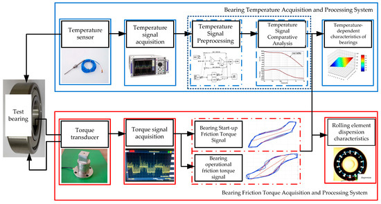
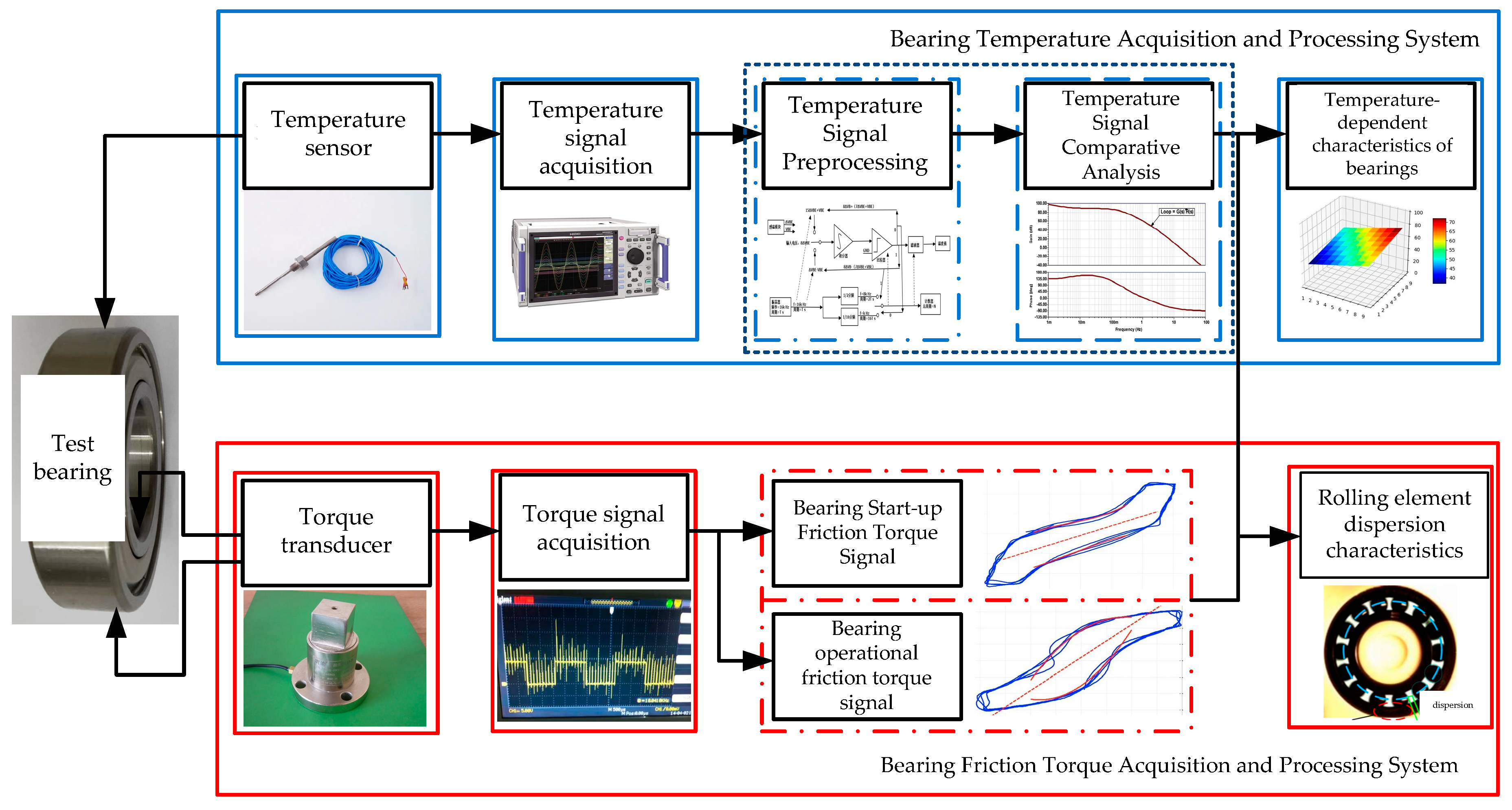
This dynamic performance experimental system is capable of realizing three functions under approximately identical conditions: temperature acquisition of the cage-less ball bearing with localized functional grooves, acquisition of the bearing starting and running friction torque, and numerically controlled variable speed and data acquisition. Its schematic diagram is shown in Figure 4.
Figure 4.
Diagram of bearing dynamic performance test plan.
The bearing dynamic performance experimental apparatus includes: an axial and radial loading system, an air-floating three-jaw chuck, an anti-rotation and anti-slip mechanism, pressure sensors, a rear pressure controller, a motor, air bearings, torque sensors, elastic couplings, an external anti-rotation system, linear modules, a signal acquisition system, support bearings and the test bearing, a rotating shaft, a high-speed motorized spindle, oil-air lubrication, and temperature sensors.
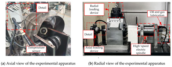
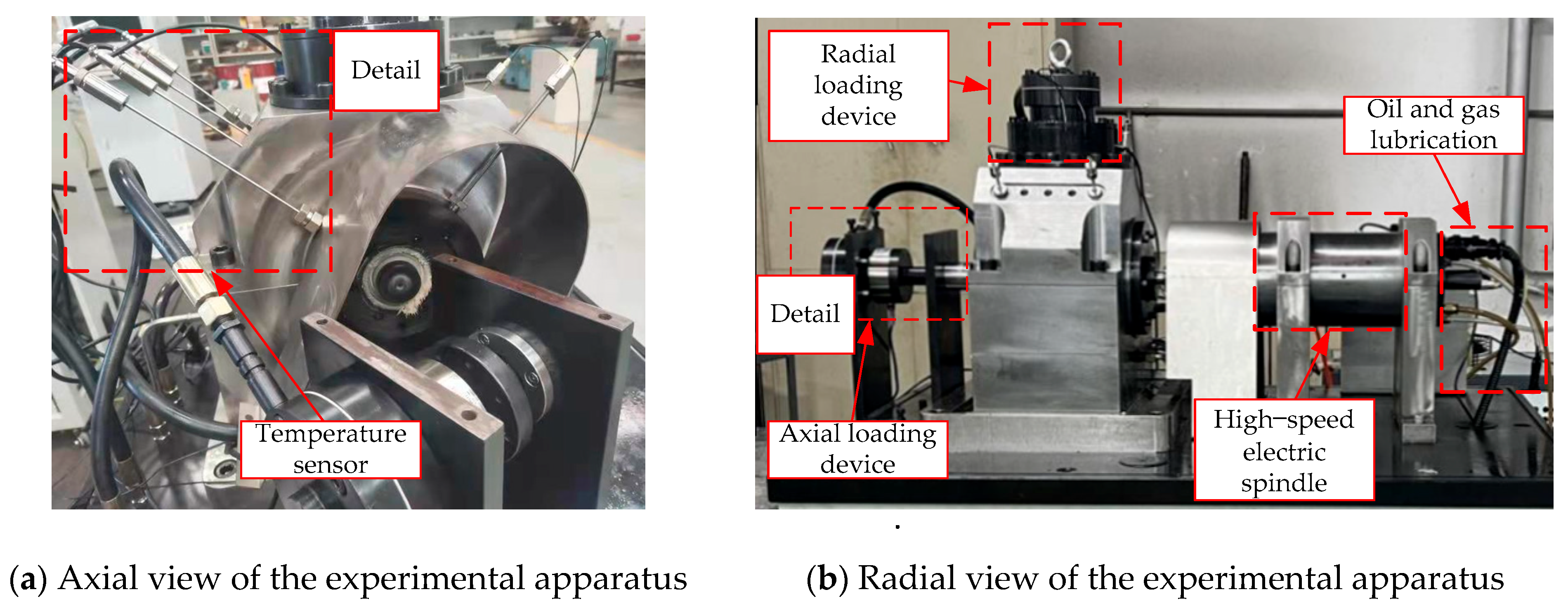
According to the experimental scheme (as shown in Figure 4), an experimental prototype of a temperature acquisition system for local functional groove cage-less ball bearings was constructed, as illustrated in Figure 5. During the experiment, use a mixture of oil and gas for lubrication of the bearings.
Figure 5.
Bearing temperature acquisition system.
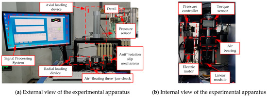
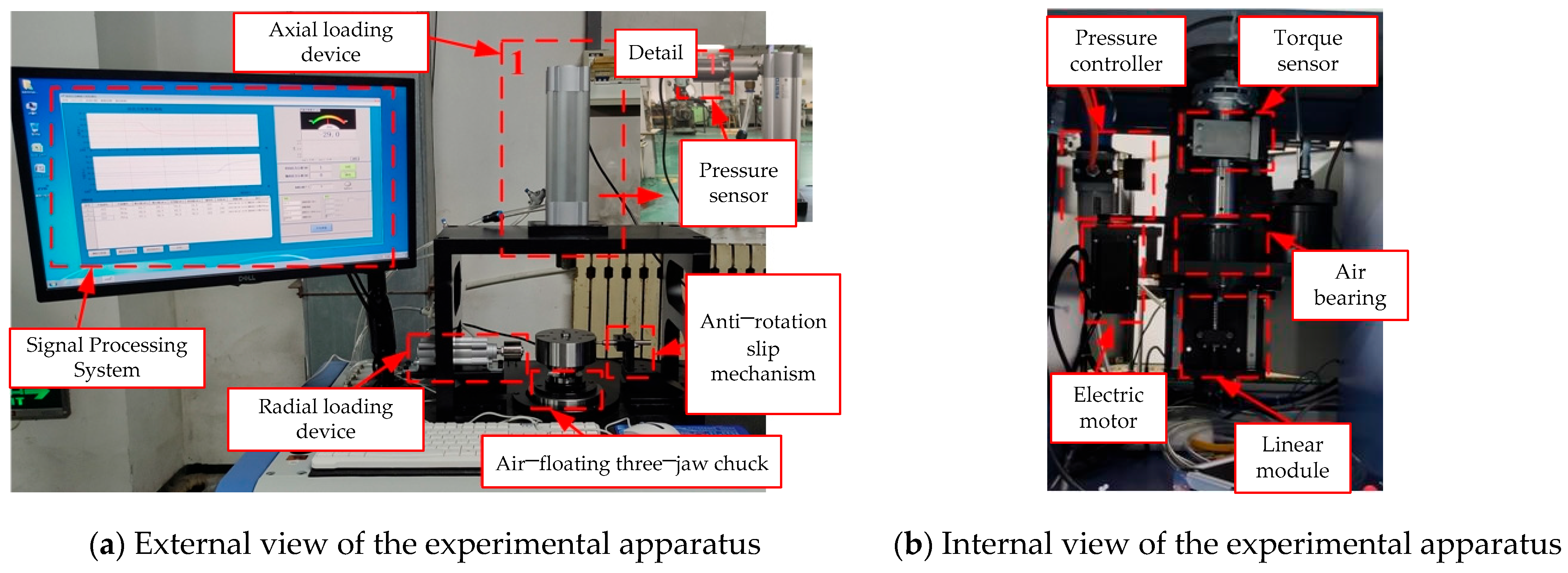
According to the experimental scheme (as shown in Figure 4), an experimental prototype for collecting the starting and running friction torque of a localized functional groove cage-less ball bearing was built, as depicted in Figure 6. During the experiment, oil lubrication was used to lubricate the bearings.
Figure 6.
Friction torque collection system for bearing startup and operation.
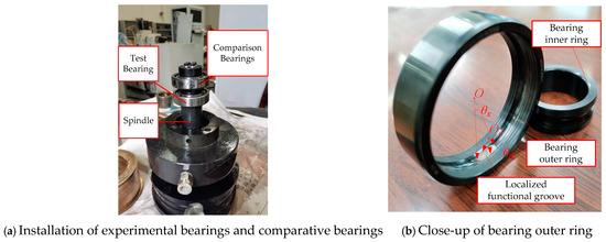
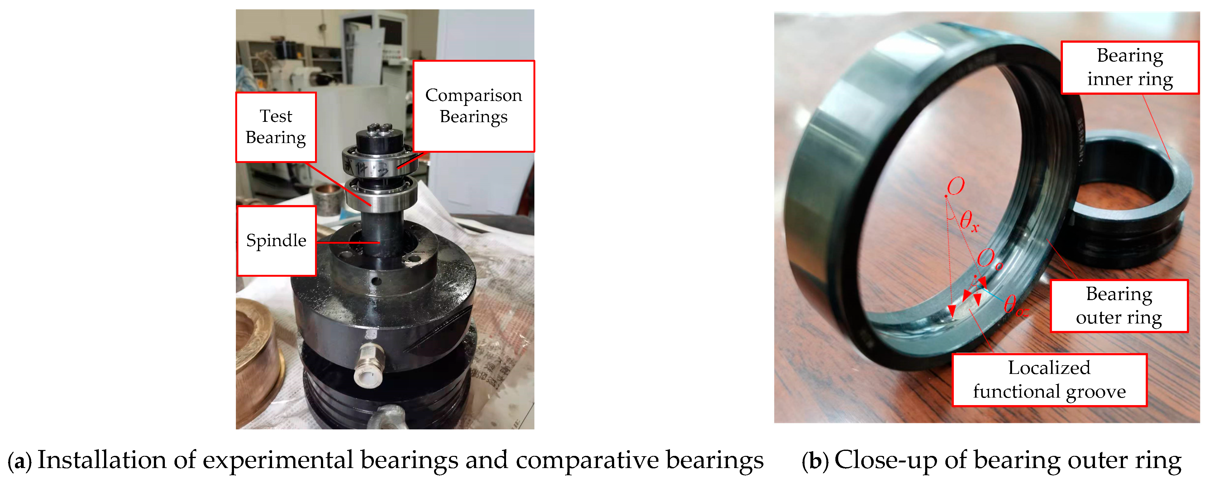
During temperature variation acquisition in the bearing dynamic performance experiment, to collect data more accurately, the temperature sensor was installed with its measurement direction at a 45° angle to the radial loading device [32]. To achieve the function of comparing the cage-less ball bearing with localized functional grooves and a conventional angular contact ball bearing under approximately identical conditions, this section adopts a back-to-back mounting arrangement to install the comparison bearing and the test bearing on the spindle of the bearing testing machine, as shown in Figure 7.
Figure 7.
Comparison of bearing installation with test bearing installation, and close-up of the outer ring of the bearing with localized functional groove.
Using the temperature measurement module of the T10-60 testing machine, temperature variation comparison experiments were conducted [33]. The parameters of the test bearing and the comparison bearing are shown in Table 1.
Table 1.
Localized functional groove test bearing parameters.
After measuring the temperatures of the two bearings under the same environmental conditions using the prototype of the bearing temperature acquisition system, it is necessary to conduct a theoretical analysis of bearing heat generation, heat transfer, and heat exchange in order to accurately analyze the causes of temperature variations in subsequent steps. Based on the models of the interaction between the rolling elements and the localized functional grooves and the interaction between adjacent rolling elements, a total kinetic energy model for the cage-less ball bearing with localized functional grooves is developed:
where Troller represents the kinetic energy of the rolling elements; Tout represents the kinetic energy of the bearing outer race; Tin represents the kinetic energy of the bearing inner race.
Similarly, a total potential energy model for the cage-less ball bearing with localized functional grooves is established:
where Vroller represents the potential energy of the rolling elements; Vt represents the potential energy generated by the contact between the rolling elements and the raceways and localized functional grooves; Vout represents the potential energy of the bearing outer race; Vin represents the potential energy of the bearing inner race.
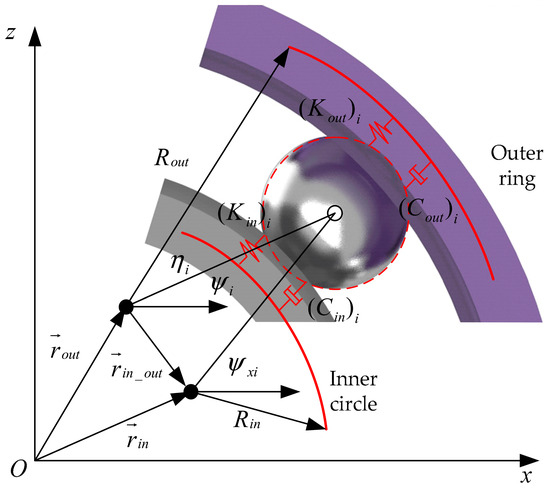
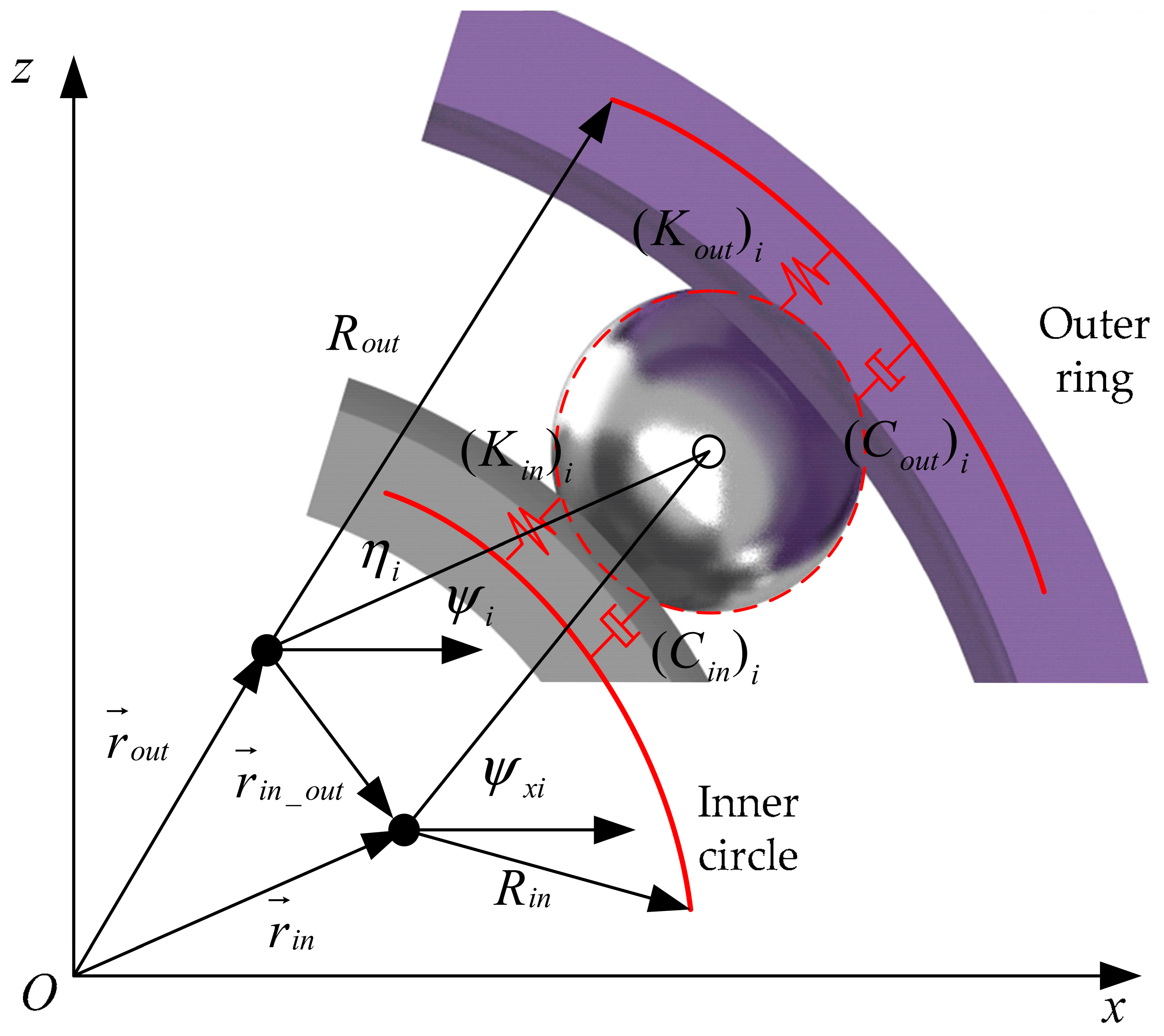
Based on the bearing coordinate system and the interaction models of various components, a schematic diagram of the kinetic-potential energy principle for the rolling elements and raceways is constructed, as shown in Figure 8.
Figure 8.
Schematic diagram of dynamic potential energy of rolling element and raceway.
Based on the contact pattern between the rolling elements and the outer ring shown in Figure 8, a kinetic and potential energy model for the outer ring of the cage-less ball bearing with localized functional grooves can be established:
Similarly, a kinetic and potential energy model for the inner ring can be established:
Since the position of the centroid of the rolling element is fixed relative to the geometric center of the outer ring, this section combines the mass mb band the centroid displacement vector in Figure 8 to establish the kinetic energy model for the rolling elements of the cage-less ball bearing with localized functional grooves:
Since the bearing outer ring is connected to the bearing housing and is relatively stationary, the kinetic and potential energy models for all rolling elements of the bearing can be established by combining Equation (5):
where Z represents the number of rolling elements; Ro represents the radius of the contact point between the rolling element and the outer ring.
Since the contact between the rolling elements and the inner and outer raceways is a non-smooth process, a potential energy model generated by the contact between the rolling elements and the raceways and localized functional grooves can be established by combining the multibody dynamics model:
By substituting Equation (7), Equation (6), and Equation (4) into Equation (1) and Equation (2) respectively, the total heat generation model for the cage-less ball bearing with localized functional grooves can be established:
It can be seen from Equation (8) that the temperature rise during the operation of the ball bearing will inevitably lead to changes in the bearing contact stiffness and the contact angles of various components, thereby affecting the dynamic performance of the cage-less ball bearing with localized functional grooves. However, at the same time, the various components connected to the bearing also facilitate heat transfer and conversion. Therefore, further analysis of the heat conduction behavior is required. First, based on the equivalent diameter and the average Nusselt number on the housing surface, a heat convection coefficient model for the bearing raceway needs to be established:
It can be seen from Equation (9) that when the rotational speed increases, the average Nusselt number increases stepwise with the speed, and since the average Nusselt number is proportional to the convection coefficient, the heat dissipation efficiency also increases stepwise with the speed, although heat generation increases accordingly. Through the heat generation model, it can be inferred that when the temperature rises, the contact stiffness of various bearing components also changes. Based on the interaction contact model, a change in contact stiffness will inevitably lead to a change in contact deformation, which in turn alters the control effect of the localized functional grooves on the rolling elements. Consequently, the velocity flow pattern in the motion channel of the rolling elements changes, which may ultimately lead to collisions between adjacent rolling elements, or even cumulative collisions. Therefore, it is necessary to analyze the bearing displacement caused by heat generation based on the principles of bearing heat generation, heat transfer, and heat exchange, and to investigate the relationship between the dispersion of bearing rolling elements and thermally induced preload.
2.2. Analysis of Dispersion Conditions for Bearings with Localized Functional Grooves
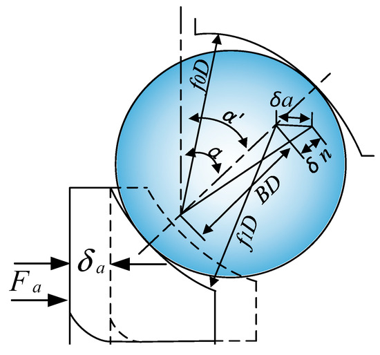
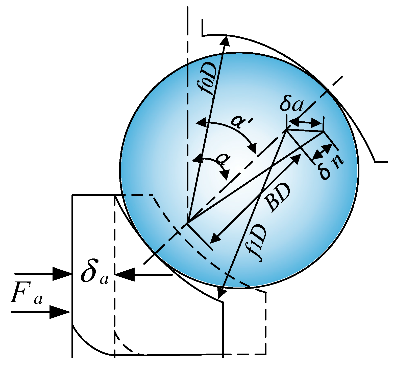
Among all bearing components, the contact area between the bearing inner ring and the rotor is relatively large. Due to differences in the heated areas, the displacement resulting from heat generation also varies. In actual operating conditions, cage-less ball bearings with localized functional grooves are typically used in pairs, meaning they are preloaded to a certain extent in the axial direction. When the bearing experiences localized displacement due to heating under preloaded conditions, new contact angles are formed between the rolling elements and the raceways, and the relevant parameters also undergo certain changes, as shown in Figure 9.
Figure 9.
Schematic diagram of local displacement of preloaded bearing.
Based on Figure 9, a mathematical model for the axial displacement under preloaded conditions when localized displacement occurs due to heat generation can be established:
where α represents the contact angle between the rolling element and the inner and outer rings after preload application; α′ represents the initial contact angle between the rolling element and the raceway; D represents the bearing diameter; B represents the raceway curvature radius.
In practical applications, cage-less ball bearings with localized functional grooves are mounted in a back-to-back configuration, connected by a sleeve in the middle, and preloaded using the position preloading method. After preload application, the forces acting on the two bearings are opposite in direction along the axis. Due to the mounting structure, the bearing closer to the shaft end on the outside bears a greater load compared to the bearing located further inward. Therefore, models for the axial thermal displacement generated after preload application for the two bearings are established:
where δp represents the axial displacement caused by preload application.
The difference in force on the two bearings after preload application is the force Fa generated by the preload on the rotor. We established a model for the relationship between Fa and the changed contact angle and initial contact angle of the cage-less ball bearing with localized functional grooves:
where K represents the displacement constant related to the bearing structural curvature.
It can be seen from Equation (9) that the contact angle α between the rolling elements and the inner and outer rings after preload application is an acute angle, while the initial contact angle α′ is 20°. Therefore, as the contact angle decreases, the force Fa generated by the preload on the rotor also gradually decreases. The overall dispersion effect of the rolling elements is related to the contact angle. Within a certain range, as the rotational speed increases, the contact angle decreases, collisions between adjacent rolling elements are reduced, and the dispersion effect improves. In summary, the stability of the overall dispersion effect of the rolling elements is related to the thermally induced preload. As the thermally induced preload increases, provided it does not exceed a threshold, the dispersion effect of the rolling elements becomes more stable.
3. Results and Discussion
Heat generation in bearings is a critical factor that cannot be overlooked when analyzing bearing dynamic performance, particularly for the cage-less ball bearing with localized functional grooves designed in this study. Due to the specific requirements of its actual operating conditions, this bearing must not only generate minimal heat during operation but also avoid heat accumulation and facilitate rapid heat dissipation. Therefore, this section will analyze the bearing temperature variation under different operating conditions based on the heat generation, heat transfer, and heat exchange principles of this bearing established in Section 2.2, aiming to investigate the bearing’s response performance to temperature changes.
3.1. Comparative Analysis of Temperature Variation Between Bearings with Localized Functional Grooves and Conventional Bearings
To clearly investigate the influence of the designed localized functional grooves on bearing temperature variation, experiments were conducted on the prototype of the bearing temperature acquisition system according to the experimental scheme designed in Section 2.1. The experimental measurement parameters for comparing the temperature response performance of the locally functional groove bearing designed in this paper with that of conventional bearings under startup and steady operation conditions, respectively, under the starting conditions of a rotational speed of 8000 r/min, a radial load of 500 N, and no initial axial preload, are shown in Table 2.
Table 2.
Temperature change comparison test measurement parameters.
To minimize errors, each experiment was conducted three times with the same measurement duration. After each experiment, the test bearing and the prototype of the temperature acquisition system were allowed to return to room temperature (16 °C) before the next experiment was performed. After the experiments, the temperature data were obtained. First, the maximum temperatures were extracted and compared. The comparative data of the maximum temperatures for the bearing with localized functional grooves and the conventional bearing are shown in Table 3.
Table 3.
Comparison data of temperature changes between the two types of bearings.
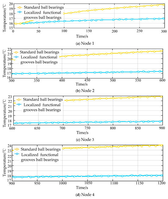
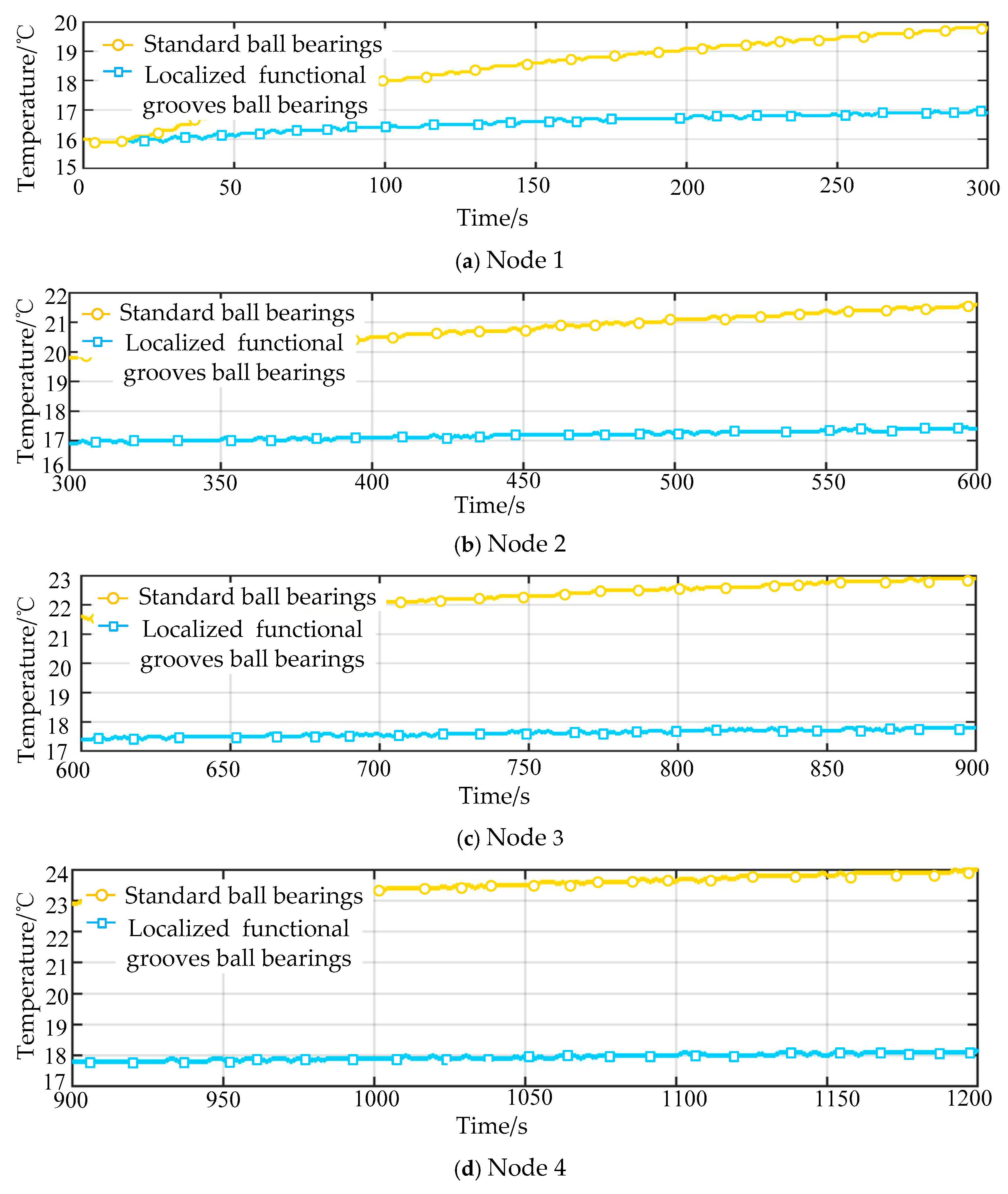
As shown in Table 3, under the same specifications and parameters, the maximum temperature of the conventional ball bearing with a cage during operation for 1200 s, 2400 s, and 3600 s was consistently higher than that of the cage-less ball bearing with localized functional grooves. Meanwhile, based on the analysis of the bearing heat generation, heat transfer, and heat exchange principles in Section 2.2, it can be seen that after the cage pocket encloses the bearing rolling elements, the heat dissipated per unit area in contact with the air decreases. In contrast, the cage-less ball bearing with localized functional grooves has no cage. Even if localized cumulative collisions and collisions between adjacent rolling elements occur, the heat is rapidly exchanged with the air because there is no cage obstructing in the axial and radial directions. To facilitate observation and comparison of the heat increase per unit time for the two types of bearings, the data obtained from the three repeated experiments were averaged to generate temperature-time curves. Figure 10 shows the comparison of temperature rise for Experiment No. 1 (test duration 1200 s).
Figure 10.
Comparison chart of temperature rise for Experiment 1.
As shown in Figure 10, the operating time for Experiment 1 was 1200 s, which belongs to the period from the startup phase to the just-entered steady-state operation phase of the bearing (Node 1 to Node 4). Nodes 1 to 3 are within the startup phase. During bearing startup, the temperature of both the conventional ball bearing and the cage-less ball bearing with localized functional grooves showed a clear upward trend, but the increase was particularly significant for the conventional ball bearing. Node 4 is between the startup phase and the steady-state operation phase. Compared with Nodes 1–3, the rate of temperature increase for both bearings showed a decreasing trend, with the cage-less ball bearing with localized functional grooves exhibiting a greater reduction in the increase rate. This indicates that at this stage, the heat generation of the bearing and its heat transfer and heat exchange were approximately equal. On the curve for each node, there are certain areas of sharp temperature increase. Since both bearings were installed on the same spindle simultaneously, it can be analyzed that when the surge areas on the two curves occurred at the same moment and the temperature amplitudes were the same, the cause of the temperature surge was external to the bearings. The two curves also showed surge areas at different points in time. Based on theoretical analysis, the temperature surges may be attributed to the following reasons: 1. Slippage of the rolling elements occurs, leading to a change in contact stiffness; 2. Collisions occur between the rolling elements and the cage in the conventional ball bearing, and collisions occur between adjacent rolling elements in the cage-less ball bearing with localized functional grooves.
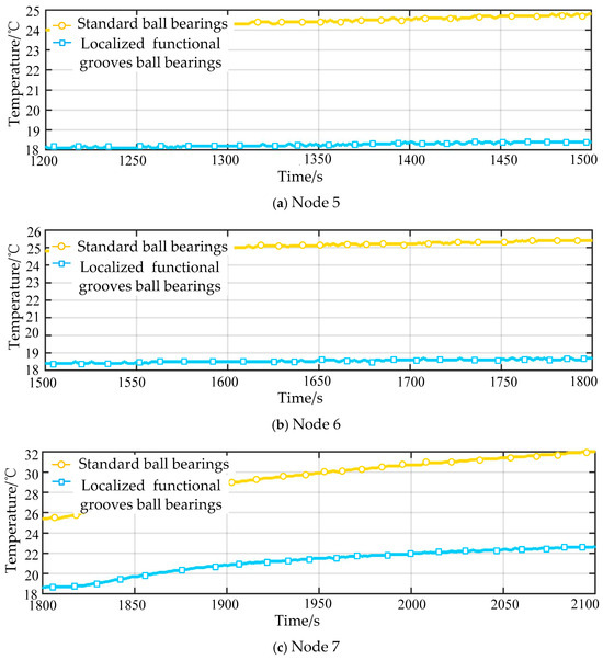
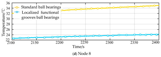
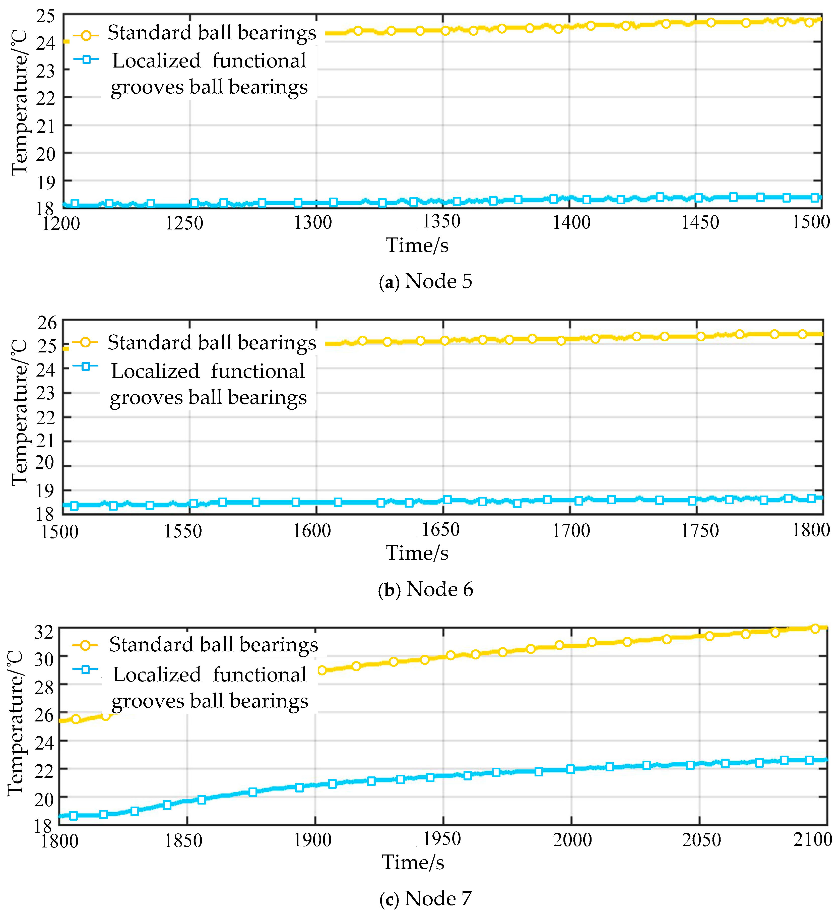
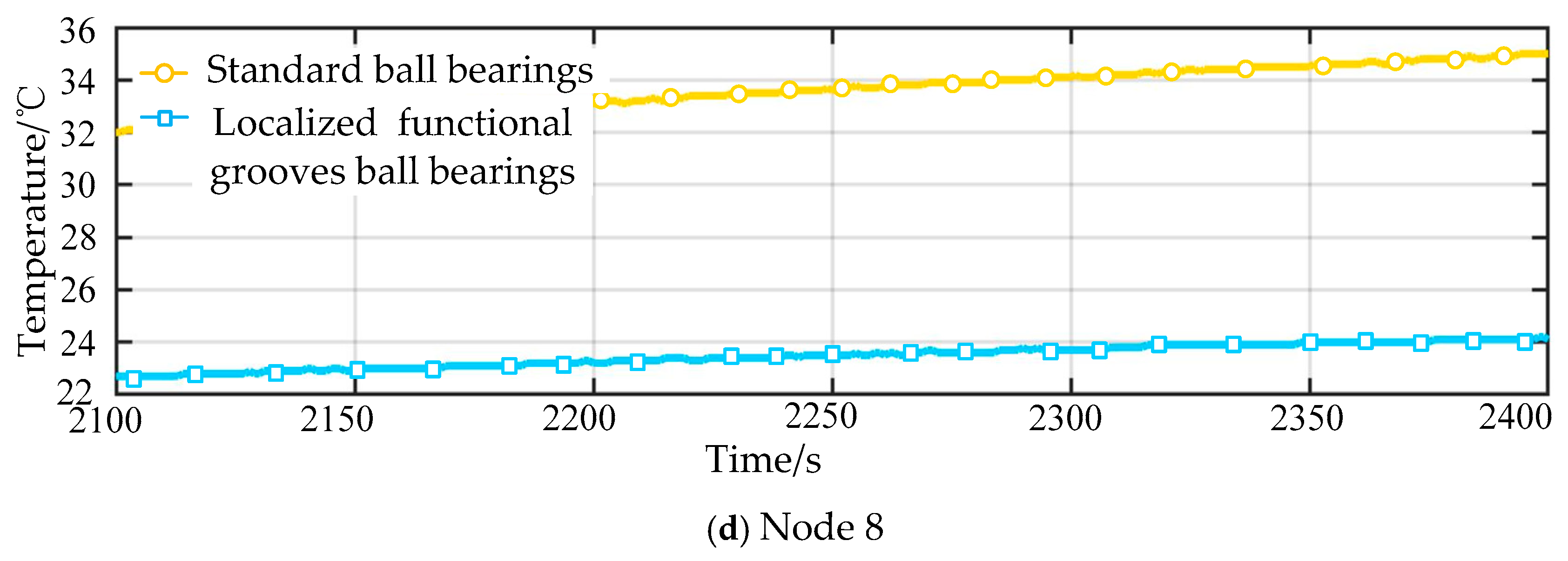
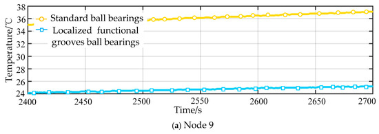
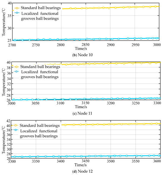
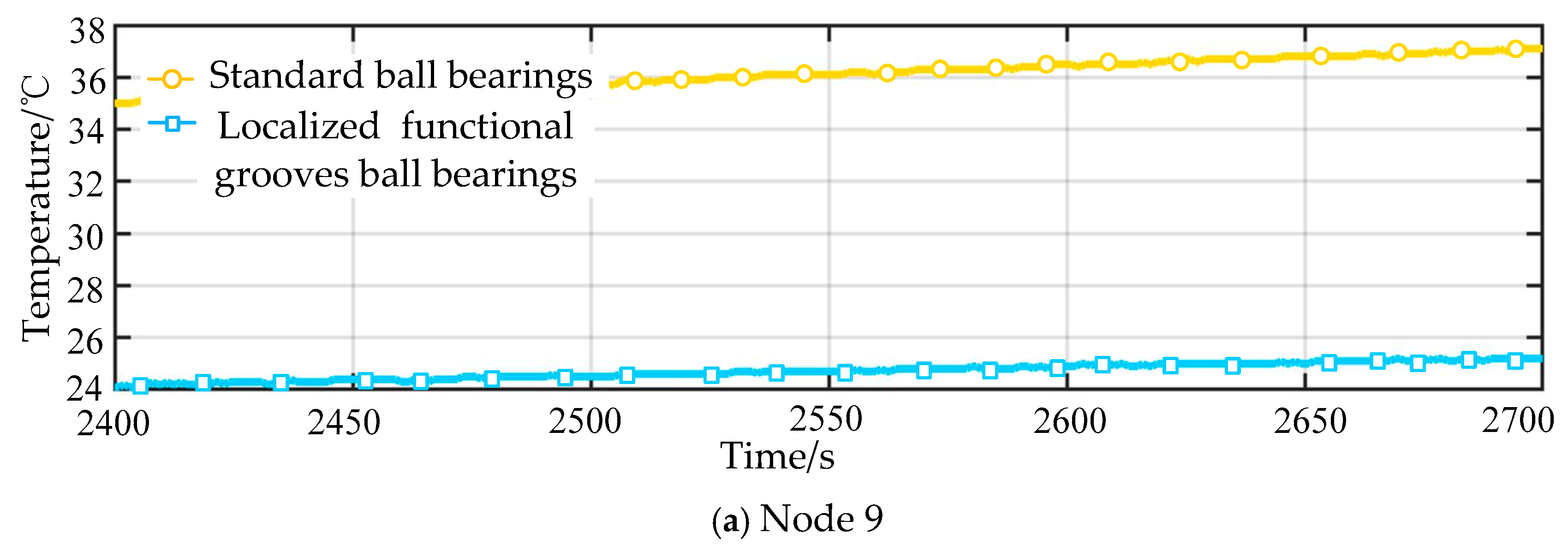
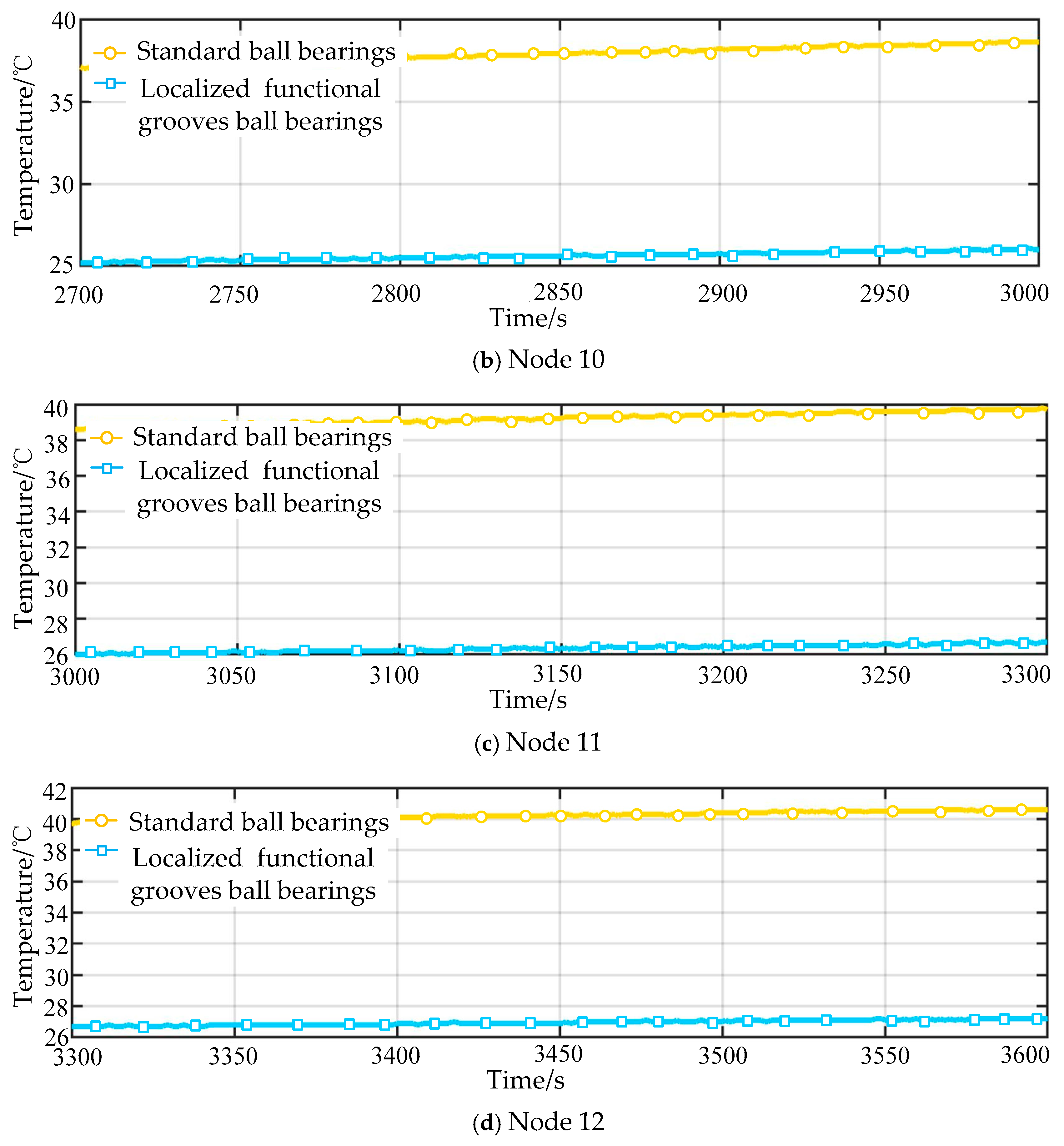
After analyzing the data from temperature variation comparative measurement Experiment 1, this study proceeds to analyze the data from Experiment 2. As the data from Experiment 1 show, the first 1200 s belong to the startup phase and part of the steady-state operation phase. According to Table 2, the rotational speed, initial preload force, and bearings used in Experiment 2 and Experiment 3 are the same as those in Experiment 1. Therefore, this study only organizes and analyzes the data for the period from 1200 s to 2400 s in Experiment 2 and from 2400 s to 3600 s in Experiment 3. The comparison charts of temperature variation for Experiment 2 and Experiment 3 are shown in Figure 11 and Figure 12, respectively.
Figure 11.
Comparison chart of temperature rise for Experiment 2.
Figure 12.
Comparison chart of temperature rise for test Experiment 3.
As shown in Figure 11 and Figure 12, Nodes 5 and 6 are within the steady-state operation phase. The temperature variation amplitude of the cage-less ball bearing with localized functional grooves was within 0.5 °C, while that of the conventional ball bearing during this phase was 1 °C. At Node 7, the temperature of both bearings suddenly surged, with an increase of approximately 4 °C. This was caused by the changing motion patterns of the bearing components as the rotational speed increased. As the rotational speed increased, the contact angle decreased, the bearing operation became unstable, and the contact stiffness between the rolling elements and the inner and outer raceways changed continuously, leading to the sudden temperature rise. However, as the speed further increased, the centrifugal force enhanced its control over the rolling elements, causing the bearing operation to stabilize again. This process is reflected in the temperature variations from Node 8 to Node 10. At Nodes 10 and 11, the temperature curves for both bearings leveled off, with almost no significant fluctuations. The conventional ball bearing stabilized at around 40 °C, while the cage-less ball bearing with localized functional grooves stabilized at around 26.5 °C. The analysis of each node through Figure 11 and Figure 12 validates the correctness of the aforementioned theory. It also demonstrates that the cage-less ball bearing with localized functional grooves designed in this study exhibits superior temperature change response performance compared to the conventional ball bearing of the same specifications. During the analysis of the experimental data, it was observed that the temperature of the bearings surged suddenly after the steady-state operation phase (Node 7). To address this issue, this study will conduct temperature variation acquisition experiments on the cage-less ball bearing with localized functional grooves under variable speed conditions.
3.2. Analysis of the Influence of Variable Speed on Temperature Variation of the Cage-Less Ball Bearing with Localized Functional Grooves
To investigate the influence of the designed localized functional grooves on bearing temperature variation under variable speed conditions, experiments were conducted on the prototype of the bearing temperature acquisition system according to the experimental scheme designed in Section 2.1. The conventional bearing used in the comparative experiment was removed, leaving only the cage-less ball bearing with localized functional grooves in the setup. An additional temperature sensor was installed, so that three sensors measured the temperature at the front end of the bearing, the bearing itself, and the rear end of the bearing, respectively. After data acquisition, the temperature change response performance of the cage-less ball bearing with localized functional grooves during the entire operation phase was compared under four different operating speeds and an initial preload of 500 N (no initial axial preload). Similarly, three experiments were conducted for each speed, and the data were averaged. The experimental measurement parameters are shown in Table 4.
Table 4.
Variable speed affects bearing temperature test measurement parameters.
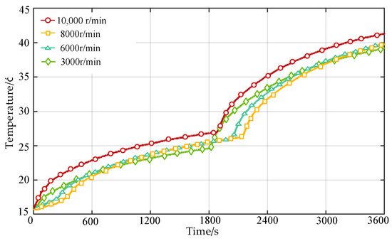
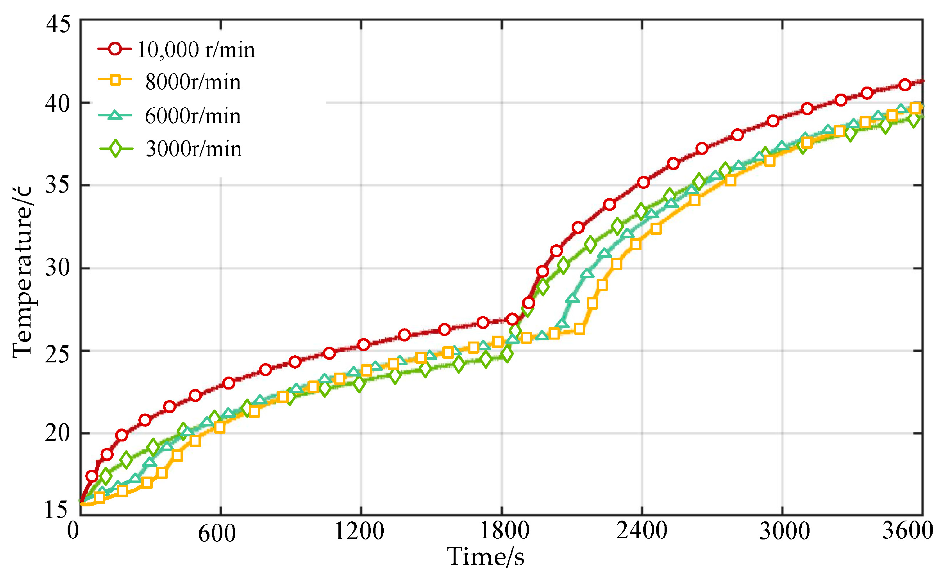
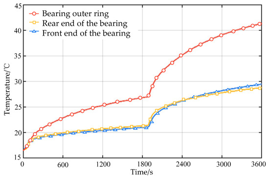
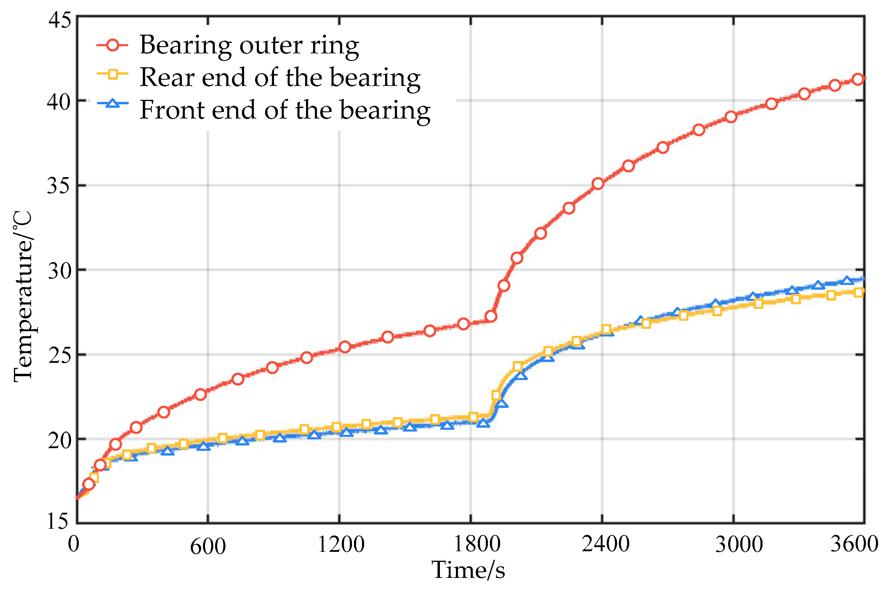
To facilitate an intuitive observation of the heat generation of the cage-less ball bearing with localized functional grooves under step-changing speed conditions, the temperature data from Experiments 1, 2, 3, and 4 are plotted together on the same graph for comparison, generating temperature-time curves. While analyzing the bearing temperature response, temperature signals from the front end, the bearing body, and the rear end at a rotational speed of 10,000 r/min, collected via the three sensors, are used to analyze its heat dissipation performance. The temperature response diagram of the bearing under variable speed conditions is shown in Figure 13, and the temperature response diagram of the bearing front end, body, and rear end is shown in Figure 14.
Figure 13.
Temperature response diagram of bearings under variable speed operating conditions.
Figure 14.
Temperature response diagram of bearing front, rear, and body.
As shown in Figure 13, the influence of variable speed conditions on the temperature response of the cage-less ball bearing with localized functional grooves is generally consistent. In each case, the temperature rises rapidly for a period, after which the rate of increase slows down. After operating for a certain duration, this trend repeats until the temperature stabilizes continuously around 40 °C. From the temperature-time curves, it can be observed that when the bearing operates at a relatively low speed (3000 r/min in this experiment), the temperature fluctuations are the greatest. At a certain moment, the temperature is even the same as that of the bearing under the 10,000 r/min condition. This is because when the bearing speed is low, the probability of collision between adjacent rolling elements is higher, resulting in greater heat accumulation transferred to the outer ring. Therefore, it can be further analyzed that the higher the bearing rotational speed, the more similar its heat variation pattern becomes, and the more stable the temperature response of the cage-less ball bearing with localized functional grooves is.
As shown in Figure 14, due to installation factors—specifically, the narrow side of the bearing facing outward and differences in heat dissipation and transfer convenience—the temperature at the front end of the bearing was slightly lower than that at the rear end both before and for a period after the temperature surge. However, after the temperature surge, the temperature at the front end of the bearing became slightly higher than that at the rear end. This is because, after the rotational speed increases to a certain value, the bearing contact angle decreases. Simultaneously, the temperature rise causes a small amount of thermal displacement toward the narrow side of the bearing inner ring, resulting in a slight shift of bearing heat toward the front end.
As shown in Figure 13 and Figure 14, within 0 to 1800 s, the lubricating oil inside the bearing gradually distributes and consumes under the agitation of the rolling elements. By around 1800 s, the effective amount of lubricant in the raceway becomes insufficient, the thickness of the oil film is insufficient or even completely ruptured, and the rolling elements and raceway transition from “fluid lubrication” to “boundary lubrication/dry friction”. The friction coefficient rises sharply from 0.001 to 0.01 and then to over 0.1; the heat generation power increases by an order of magnitude, and the temperature rises rapidly.
Having confirmed that the designed cage-less ball bearing with localized functional grooves exhibits favorable temperature change response performance, this study will next utilize the prototype of the bearing starting and running friction torque acquisition system to conduct relevant experiments. These experiments aim to investigate the influence of varying radial load, axial load, and operating speed on the dispersion performance of the rolling elements, and to evaluate and optimize the suitable operating conditions for the designed bearing.
3.3. Experimental Analysis of the Dispersion Performance of Rolling Elements in Bearings with Localized Functional Grooves
The bearing friction torque is an important reference for evaluating the dynamic performance of bearings, particularly for the cage-less ball bearing with localized functional grooves designed in this study. Due to the specific requirements of its actual operating conditions, the bearing needs to transmit rotational torque quickly while reducing collisions between rolling elements. Therefore, based on the dispersion conditions of the rolling elements considering thermally induced preload, this section will utilize starting and dynamic friction torque experiments to investigate the dispersion response performance of the bearing under combined loads and varying rotational speeds.
3.3.1. Analysis of the Influence on Rolling Element Dispersion Performance During the Startup Phase
To investigate the factors influencing the dispersion performance of rolling elements during the startup phase after the introduction of localized functional grooves, this section conducts comparative experiments on the startup phase of the cage-less ball bearing with localized functional grooves and a conventional ball bearing, using the prototype of the bearing starting and dynamic friction torque acquisition system according to the experimental scheme designed in Section 2.1. After data acquisition, the changes in friction torque during the startup phase for the two bearings are compared under conditions of varying radial load, axial load, and starting angle. During the experiment, the acquisition system was set to 72 measurement points, with the measurement angle changing by 5° each time, and the rotational speed for each measurement was 10 r/min. To control errors and eliminate rotational inertia, the system was stopped for 2 s after each change in measurement angle. Similarly, each experiment was conducted three times, and the data were averaged. The experimental measurement parameters for the bearing starting friction torque are shown in Table 5.
Table 5.
Test parameters for measuring the starting friction torque of bearings.
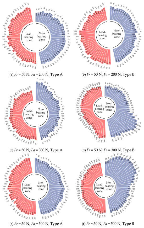
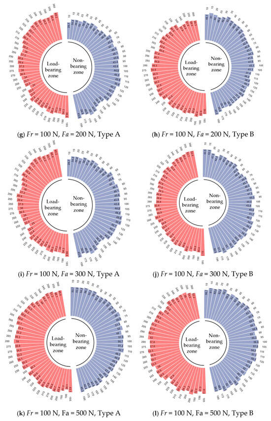
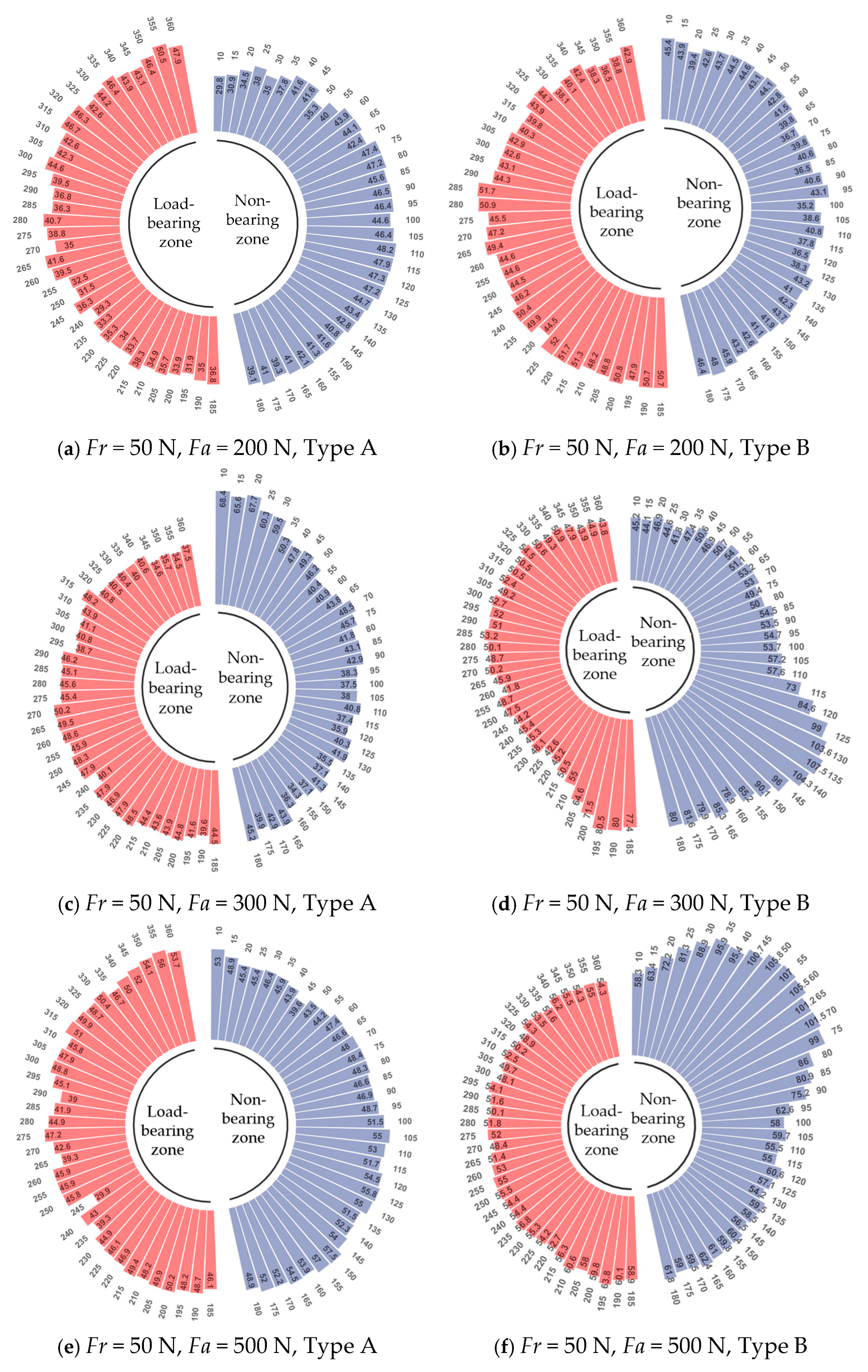
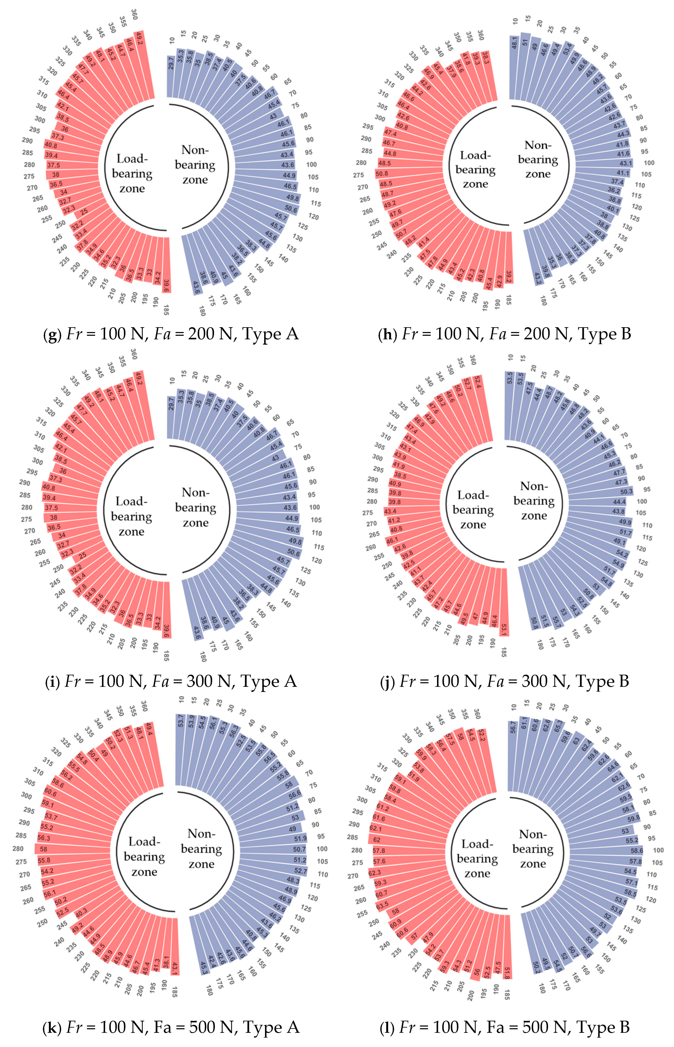
To facilitate analysis in conjunction with the bearing structure, this section processes the data from Experiments 1–6 for the bearing with localized functional grooves and the data from Experiments 7–12 for the conventional ball bearing into annular bar charts, and, for ease of analysis, marks the loaded zone and unloaded zone in the charts, as shown in Figure 15.
Figure 15.
Ring diagram of bearing starting friction moment.
As shown in Figure 15, the variation patterns of the starting friction torque data for the bearing with localized functional grooves under six different operating conditions are essentially the same. This indicates that during the bearing startup phase, the localized functional grooves can control the rolling elements to prevent cumulative collisions. After passing through the localized functional grooves (at the 270° position), the rolling elements can achieve self-dispersion. In contrast, the starting friction torque data for the conventional ball bearing varied significantly under the six conditions, indicating severe collisions between the rolling elements and the cage, which increased the rotational resistance of the bearing inner ring. In summary, during the startup phase, the bearing with localized functional grooves is far superior to the conventional ball bearing in rapidly dissipating the torsional force of the rotor when used as a backup bearing for magnetic bearings. Analysis of Figure 15a,c,e,g,j,l shows that the influence of axial load on the self-dispersion of the rolling elements is greater than that of radial load, while the influence on the loaded zone is less than that on the unloaded zone. This is due to the unloading effect provided by the localized functional grooves. However, increasing the axial load still increases the value of the starting friction torque, thereby affecting the self-dispersion of the rolling elements. Analysis of Figure 15b,d,f,h,j,k reveals that the response magnitude of the bearing with localized functional grooves to changes in combined loads is far smaller than that of the conventional ball bearing. This implies that when thermal displacement occurs during the startup phase due to contact between the rotor and the inner ring, the bearing with localized functional grooves can dissipate heat quickly, preventing the generation of significant thermally induced preload that could cause substantial axial friction between the bearing and the rotor. To investigate the factors influencing the dispersion performance of rolling elements during the bearing operation phase, this study will conduct dynamic friction torque data acquisition experiments.
3.3.2. Analysis of the Influence on Rolling Element Dispersion Performance During the Operation Phase
To investigate the factors influencing the dispersion performance of rolling elements during the operation phase after the introduction of localized functional grooves, this section conducts comparative experiments on the operation phase of the cage-less ball bearing with localized functional grooves and a conventional ball bearing, using the prototype of the bearing starting and dynamic friction torque acquisition system according to the experimental scheme designed in Section 2.1. After data acquisition, the changes in friction torque during the operation phase for the two bearings are compared under conditions of varying radial load, axial load, and rotational speed. To avoid the influence of the startup phase on the friction torque value, the bearings were pre-run for 5 s before the measurement, and the measurement cycle covered 12 revolutions. To control experimental errors, each experiment was conducted three times, and the data were averaged. The experimental measurement parameters for the bearing dynamic friction torque are shown in Table 6.
Table 6.
Measurement parameters for dynamic friction torque test of bearings.
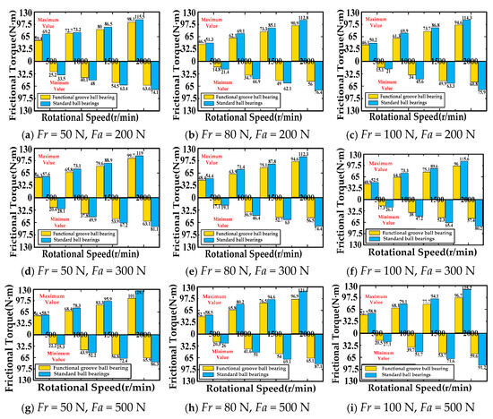
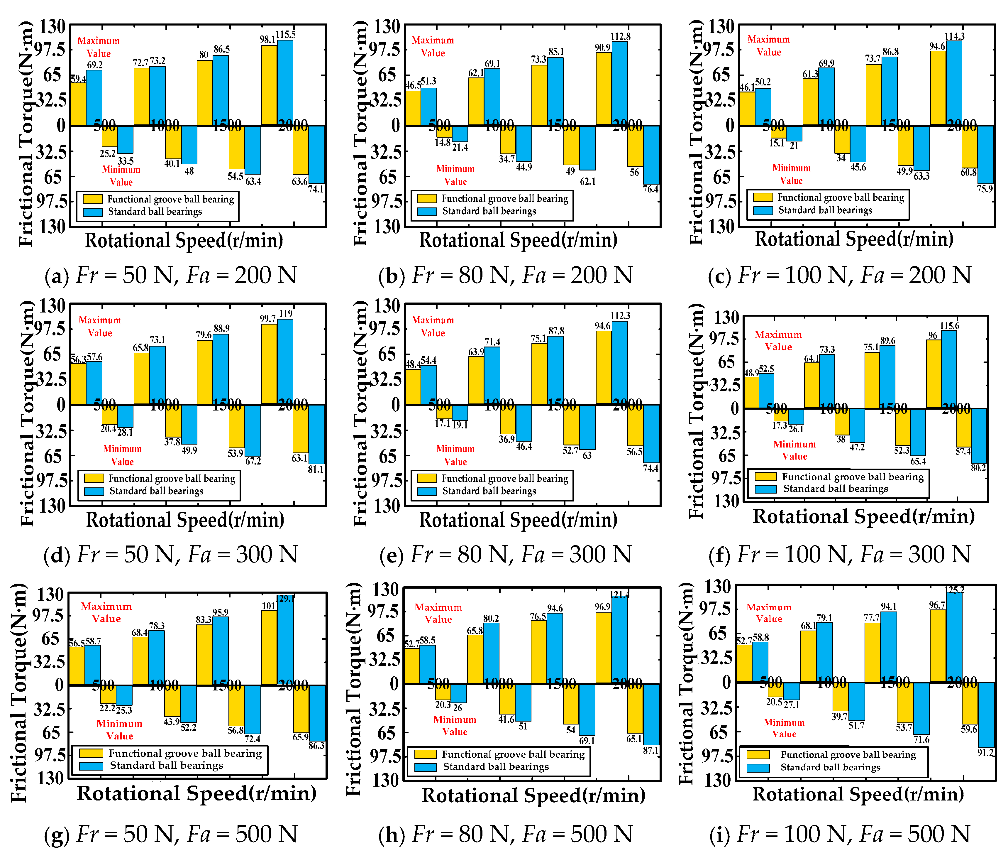
To facilitate comparative analysis, this section takes the maximum and minimum values of the dynamic friction torque data for the bearing with localized functional grooves and the conventional ball bearing, and forms a double-column histogram of friction torque according to the speed gradient, as shown in Figure 16.
Figure 16.
Dual column histogram of bearing speed gradient dynamic friction moment.
As can be seen from Figure 16, when the bearings operate under the same parameters, the dynamic friction torque (i.e., the maximum and minimum values of the friction torque) of the bearing with localized functional grooves is reduced by approximately 12% to 34% compared to the conventional ball bearing. There is an inverse relationship between radial load and the dynamic friction torque of both bearing types, and a direct relationship between axial load and the dynamic friction torque of both bearing types. However, changes in the combined load do not significantly affect the friction torque value itself. For the bearing with localized functional grooves, neither the maximum nor the minimum values of the dynamic friction torque showed a sharp increase when facing either varying combined loads or varying rotational speeds. This indicates that during operation, although the effect of the localized functional grooves may gradually weaken under complex operating conditions, no sudden failure occurs, and the dispersion state of the bearing rolling elements remains relatively stable.
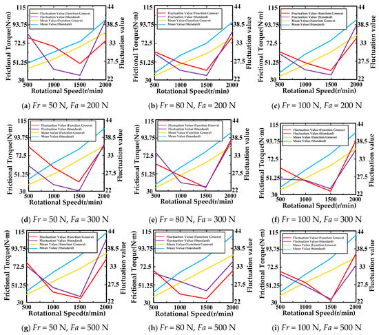
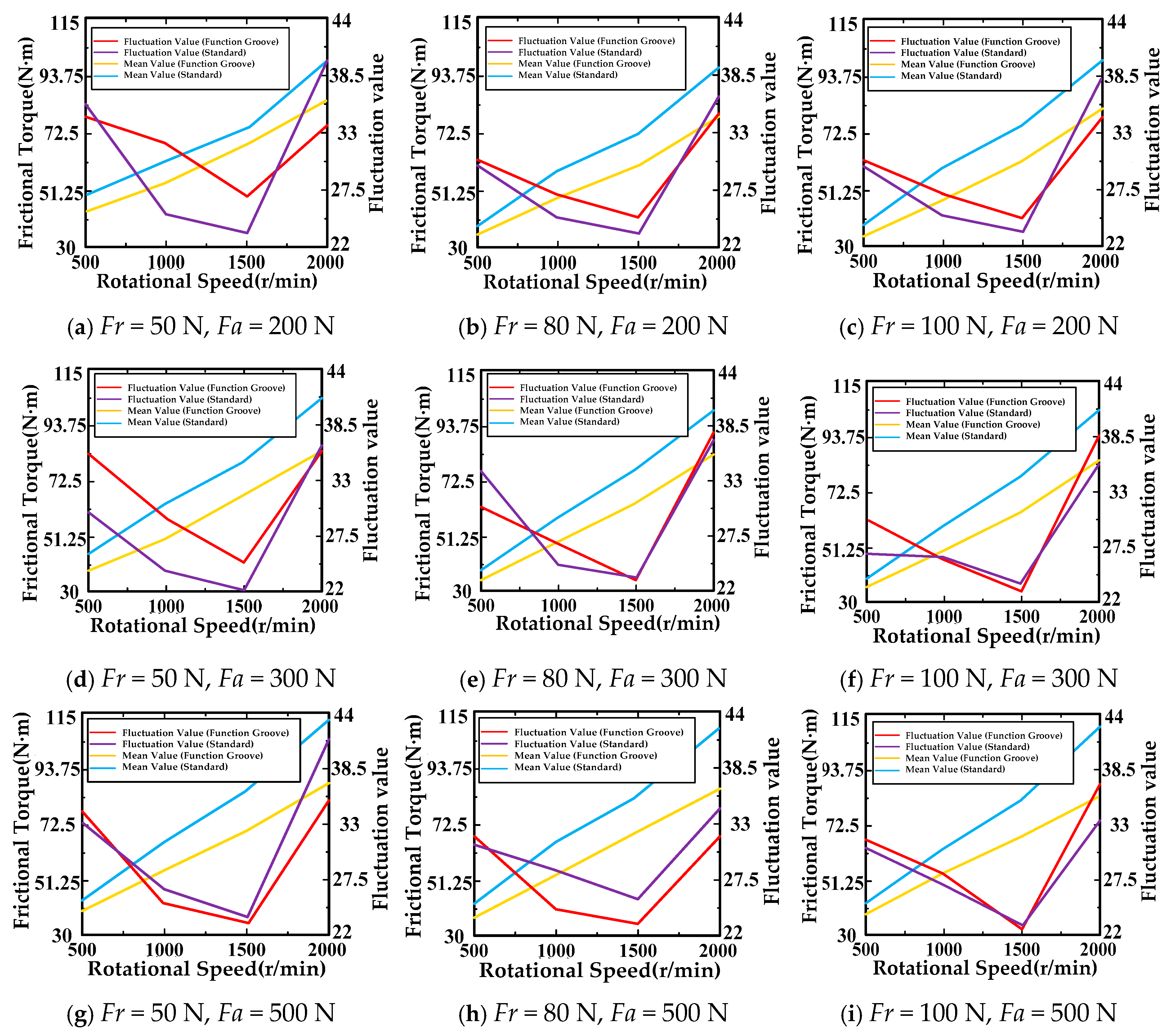
To further compare the stability of the dynamic friction torque between the bearing with localized functional grooves and the conventional ball bearing, this section calculates the average values and fluctuation values of the experimental data, and generates a line chart of the dynamic friction torque according to the speed gradient, as shown in Figure 17.
Figure 17.
Line chart of friction torque during bearing operation stage.
The following conclusions can be drawn from Figure 17:
- (1)
- Under constant radial and axial loads, the average value of the dynamic friction torque reflects that as the rotational speed increases, the difference in the control of the rolling elements between the bearing with localized functional grooves and the conventional ball bearing also increases. When the rotational speed increased from 500 r/min to 2000 r/min, the difference in their ability to control the rolling elements grew by approximately 14%. This indicates that the higher the speed at which the rotor drops, the more stable the average dynamic friction torque of the bearing with localized functional grooves becomes, and the number of collisions between adjacent rolling elements is fewer compared to the collisions between the rolling elements and the cage in the conventional bearing.
- (2)
- At a constant rotational speed, as the combined load changes, the average friction torque of the bearing with localized functional grooves is consistently lower than that of the conventional bearing. This indicates that under complex load conditions, the bearing with localized functional grooves can more easily control the revolution of the rolling elements, reduce collision friction, and result in less damaging friction fed back to the rotor.
- (3)
- From the perspective of the dynamic friction torque fluctuation value, this experimental value represents the degree of uncertainty caused by changes in the friction torque during bearing operation. Combined with the analysis of the chaotic motion characteristics of the bearing inner ring and rolling elements, it can be seen that the motion uncertainty of the bearing with localized functional grooves arises from the absence of a cage to constantly control the revolution of the rolling elements. This was also demonstrated in Figure 17. However, considering that the bearing with localized functional grooves is designed for application scenarios as a backup bearing for active magnetic bearings, it does not operate for long periods in actual use, so the impact of increased uncertainty is much smaller.
- (4)
- From the perspective of the influence of rotational speed on the dynamic friction torque fluctuation value, the larger fluctuation at lower speeds indicates a higher number of collisions between the rolling elements of the bearing with localized functional grooves. As the rotational speed increases, the rolling elements gradually separate under the effect of the localized functional grooves. Regarding the influence of combined load on the dynamic friction torque fluctuation value, the bearing with localized functional grooves is more suitable for operating conditions with larger axial loads. This is because the pressure provided by the axial load on the bearing rolling elements helps reduce the degree of uncertainty in their motion.
4. Conclusions
This paper proposes an experimental scheme to determine the dynamic performance of the degree of rolling element dispersion by collecting and analyzing the changes in bearing temperature and friction torque. Based on the preliminary experimental results, suitable operating conditions for the cage-less ball bearing with localized functional grooves designed in this study were identified. Firstly, the principle and scheme of the dynamic performance experimental system were designed. Based on this, a heat convection coefficient model for the bearing raceway was established. Considering thermally induced preload, the relationship between changes in bearing temperature and friction torque and the degree of rolling element dispersion was determined, providing a theoretical basis for analyzing the experimental results. Finally, experimental verification shows that the bearing with localized functional grooves is superior to conventional ball bearings in terms of temperature change response and in reducing the probability of friction by dispersing the rolling elements. Furthermore, based on the preliminary experimental results, it is determined that the cage-less ball bearing with localized functional grooves designed in this study is more suitable for operating conditions involving medium to high rotational speeds, relatively large axial loads, and a need for relatively high starting torque.
5. Discussion
- As a key unit for adjusting local performance in structural design, the localized functional grooves’ parameters such as size, shape, and distribution mode directly affect the local stiffness and contact deformation characteristics of the structure through changes in stress transfer paths and material distribution states, thereby influencing temperature and frictional torque variations. In subsequent research, the impact of localized functional grooves on the raceway itself should be incorporated into the study.
- The localized functional grooves induce non-stationarity in the inherent characteristics of the structure, posing significant challenges for subsequent bearing condition monitoring and fault feature extraction. This non-stationarity primarily stems from the uneven local stiffness and contact deformation fluctuations caused by the localized functional grooves, which result in time-varying characteristics of vibration signals and stress distribution during the operation of the bearing, breaking the assumption of stationarity under ideal conditions. Subsequent research should incorporate considerations in this regard.
Author Contributions
Conceptualization, J.Z.; Software, E.Z.; Investigation, Y.W.; validation, Y.Z., Q.L. and Y.W.; Writing—original draft, J.Z. All authors have read and agreed to the published version of the manuscript.
Funding
This work was financially supported by the Jilin Provincial Department of Education Scientific Research Project (JJKH20251825KJ) and Jilin Tiedao University Doctoral Research Start-up Fund.
Data Availability Statement
The original contributions presented in this study are included in the article. Further inquiries can be directed to the corresponding author.
Conflicts of Interest
Authors Jingwei Zhang and Enwen Zhou are employed by the company Goertek Inc. Postdoctoral Research Station, Goertek Co., Ltd. The remaining authors declare that the research was conducted in the absence of any commercial or financial relationships that could be construed as a potential conflict of interest.
References
- Yan, H.; Bao, Z.; Qin, Z.; Niu, H. Experimental Study on the Vibration and Radiation Noise of Full Ceramic Angle Contact Ball Bearings Operating at High Speeds with Starved Lubrication. Noise Vib. Control 2023, 43, 95–101. [Google Scholar] [CrossRef]
- Wang, Y.; Shiyuan, E. Design and Research of Bearing Reliability Test Bed Based on Multi-Dimensional Vibration Loading. J. Phys. Conf. Ser. 2021, 2101, 012045. [Google Scholar] [CrossRef] [Scilit]
- Wen, B. Theoretical and Experimental Investigation of Cage Dynamics in Angular Contact Ball Bearing. Ph.D. Dissertation, Dalian University of Technology, Dalian, China, 2017. [Google Scholar] [CrossRef]
- Wei, H.; Cai, G.; Liu, Z.; Wang, S. A Fusion Non-Convex Group Sparsity Difference Method and Its Application in Rolling Bearing Fault Diagnosis. Meas. Sci. Technol. 2024, 35, 025123. [Google Scholar] [CrossRef] [Scilit]
- Chi, Y. Vibration Characteristics Analysis and Intelligent Diagnosis Method Research of Rolling Bearing Faults. Ph.D. Dissertation, Zhejiang University, Hangzhou, China, 2018. [Google Scholar]
- Tian, S. Research on Complex Dynamic Characteristics and Comprehensive Testing Technology of High-Speed Motorized Spindle System. Master’s Thesis, Chongqing University, Chongqing, China, 2019. [Google Scholar] [CrossRef]
- Pan, B. Development of Test Rig and Experimental Study on Performance of Ceramic Ball Bearing in High-Speed Electric Spindle. Master’s Thesis, Henan University of Science and Technology, Luoyang, China, 2011. [Google Scholar]
- Yun, X.; Han, Q.; Wen, B.; Hao, X. Dynamic Stiffness and Vibration Analysis Model of Angular Contact Ball Bearing Considering Vibration and Friction State Variation. J. Vibroeng. 2022, 24, 221–255. [Google Scholar] [CrossRef] [Scilit]
- Wu, C. Kinematic Characteristic Analysis and Parametric Design of Cage-Less Ball Bearing with Collision Reduction Groove. Master’s Thesis, Harbin University of Science and Technology, Harbin, China, 2023. [Google Scholar]
- Ariyoshi, S.; Kawakita, K.; Hirano, F. The Performance of a New Measuring Method for Three-Dimensional Ball Motion in a Ball-Bearing. Wear 1983, 92, 13–23. [Google Scholar] [CrossRef] [Scilit]
- Gentle, C.R.; Boness, R.J. Prediction of Ball Motion in High-Speed Thrust-Loaded Ball Bearings. J. Lubr. Technol. 1976, 98, 463–469. [Google Scholar] [CrossRef] [Scilit]
- Gao, X.; Zhang, C. Measuring Method for 3D Motion of Balls in High-speed Precision Ball Bearings. Bearing 2010, 1, 45–48+63. [Google Scholar] [CrossRef]
- Tu, W.; Lou, Y.; Liu, C.; Yu, W. Thermodynamic real-time coupling modeling and thermal characteristic analysis of angular contact ball bearings under combined loads. Acta Mech. Sin. 2026, 5, 42. [Google Scholar] [CrossRef] [Scilit]
- Qi, Q.; Ren, S.; Wang, C.; Chen, Z.; Jia, X.; Peng, X. Thermodynamic performance optimization of two-stage hydraulic-driven piston hydrogen compressors based on variable speed control method. Int. J. Hydrogen Energy 2025, 145, 205–214. [Google Scholar] [CrossRef] [Scilit]
- Xiao, C.; Chang, S. Numerical simulation of droplet impingement on supercooled curved surface based on lattice Boltzmann method. Phys. Fluids 2025, 9, 37. [Google Scholar] [CrossRef] [Scilit]
- Zmarzly, P. Experimental Assessment of Influence of the Ball Bearing Raceway Curvature Ratio on the Level of Vibration. Commun. Sci. Lett. Univ. Zilina 2020, 22, 103–111. [Google Scholar] [CrossRef] [Scilit]
- Ursache, C.; Barili, A.; Tudose, L.; Tudose, C. Optimal Design of Self-Retaining Full Complement Cylindrical Roller Bearings. IOP Conf. Ser. Mater. Sci. Eng. 2019, 591, 012065. [Google Scholar] [CrossRef] [Scilit]
- Singh, A.P.; Agrawal, A.; Joshi, D. Contact Mechanics Studies for an Elliptical Curvature Deep Groove Ball Bearing Using Continuum Solid Modeling Based on FEM Simulation Approach. Mater. Sci. 2016, 13, 1–11. [Google Scholar]
- Luo, W.; Hu, T.; Zhang, C.; Wei, Y. Digital Twin for CNC Machine Tool: Modeling and Using Strategy. J. Ambient Intell. Humaniz. Comput. 2019, 10, 1129–1140. [Google Scholar] [CrossRef] [Scilit]
- Roh, G.; Jeon, C.H.; Shim, C.S.; Park, J.; Kang, D.; Lee, Y.J. Digital twin models for management of key performance of prestressed concrete bridges. Eng. Struct. 2026, 346, 121686. [Google Scholar] [CrossRef] [Scilit]
- Hirano, F. Motion of a Ball in Angular-Contact Ball Bearing. ASLE Trans. 1965, 8, 425–434. [Google Scholar] [CrossRef] [Scilit]
- Kawakita, K.; Ariyoshi, S. The Actual Motion and the Contact Angle of a Ball in a Deep Groove Ball-Bearing II: Shaft Speed Ni = 100 rev min−1; Thrust Load Fa = 600, 800 and 1000 N. Wear 1987, 117, 251–262. [Google Scholar] [CrossRef] [Scilit]
- Villavicencio, M.; Renouf, M.; Saulot, A.; Michel, Y.; Mahéo, Y.; Colas, G.; Filleter, T.; Berthier, Y. Self-Lubricating Composite Bearings: Effect of Fibre Length on Its Tribological Properties by DEM Modelling. Tribol. Int. 2017, 113, 362–369. [Google Scholar] [CrossRef] [Scilit]
- Machado, C.; Guessasma, M.; Bellenger, E. An Improved 2D Modeling of Bearing Based on DEM for Predicting Mechanical Stresses in Dynamic. Mech. Mach. Theory 2017, 113, 53–66. [Google Scholar] [CrossRef] [Scilit]
- Machado, C.; Baudon, S.; Guessasma, M.; Bourny, V.; Fortin, J.; Bouzerar, R.; Maier, P. An Original DEM Bearing Model with Electromechanical Coupling. Int. J. Comput. Methods 2019, 16, 1840006. [Google Scholar] [CrossRef] [Scilit]
- Machado, C.; Guessasma, M.; Bourny, V. Electromechanical Prediction of the Regime of Lubrication in Ball Bearings Using Discrete Element Method. Tribol. Int. 2018, 127, 69–83. [Google Scholar] [CrossRef] [Scilit]
- Stanković, I.; Dašić, M.; Jovanović, M.; Martini, A. Effects of Water Content on the Transport and Thermodynamic Properties of Phosphonium Ionic Liquids. Langmuir 2024, 40, 9049–9058. [Google Scholar] [CrossRef] [Scilit] [PubMed]
- Dašić, M.; Stanković, I.; Gkagkas, K. Influence of confinement on flow and lubrication properties of a salt model ionic liquid investigated with molecular dynamics. Eur. Phys. J. E 2018, 41, 130. [Google Scholar] [CrossRef] [Scilit] [PubMed]
- Qin, S. Design and Kinematic Analysis of Caged-Less Bearings with Variable Surfaces. Master’s Thesis, Harbin University of Science and Technology, Harbin, China, 2020. [Google Scholar] [CrossRef]
- Helfert, M. Analysis of Anti-Friction Bearings by Means of High-Speed Videography. Experimental Analysis of the Retainer Bearing Behavior after Touchdown of a Magnetically Suspended Rotor. Tribol. Schmier. 2008, 55, 10–15. [Google Scholar]
- Kūyu Bearings/JTEKT Co., Ltd. Available online: https://koyo.jtekt.co.jp/en/ (accessed on 1 January 2000).
- Zhao, F.; van Wachem, B.G.M. A Novel Quaternion Integration Approach for Describing the Behaviour of Non-Spherical Particles. Acta Mech. 2013, 224, 3091–3109. [Google Scholar] [CrossRef] [Scilit]
- Luoyang ZhoYan Technology Co., Ltd. Available online: www.zys.com.cn/zyscp/sysb/ (accessed on 1 January 2019).

Disclaimer/Publisher’s Note: The statements, opinions and data contained in all publications are solely those of the individual author(s) and contributor(s) and not of MDPI and/or the editor(s). MDPI and/or the editor(s) disclaim responsibility for any injury to people or property resulting from any ideas, methods, instructions or products referred to in the content. |
© 2026 by the authors. Licensee MDPI, Basel, Switzerland. This article is an open access article distributed under the terms and conditions of the Creative Commons Attribution (CC BY) license.