


Abstract
This paper investigates how the thickness of dogbone tensile specimens made from heat-treated Hastelloy-X alloy produced by Laser Powder Bed Fusion (LPBF) influences their mechanical properties and microstructure. The focus of the investigation is on surfaces in an “as-built” condition and considers a range of thickness from 3 to 1 mm. The “as-built” surfaces condition is a fundamental outcome, considering that LPBF technology’s key feature is the ability to produce intricate and complex geometries that are difficult to achieve with conventional manufacturing technologies. The specimens were fabricated according to ASTM E8/E8M-21 and were heat-treated in a vacuum furnace at 1150 °C for two hours. The microstructure of the material was evaluated through porosity, EBSD, and Microhardness analyses. The mechanical properties were evaluated through tensile tests conducted at room temperature on dogbone specimens fabricated both parallel and perpendicular to the building direction. The findings indicate a significant reduction in mechanical properties that could be correlated with the reduction in specimen thickness, reflecting a gradual decline from the baseline. Specifically, a 14% decrease in Ultimate Tensile Strength (from 612 to 528 MPa), an approximately 19% reduction in Young’s Modulus (from 190 GPa to 153 GPa), and a 32% decrease in Elongation at Break (from 59.2% to 40.0%) were observed. Furthermore, it was noted that the printing orientation of the specimens significantly affects their mechanical properties, regardless of thickness. Overall, the results suggest that applying standard heat treatment under specific conditions, such as with a thin, exposed wall of about 1mm with a striped strategy, may not lead to adequate material performance.
1. Introduction
Laser Powder Bed Fusion (LPBF) technology is an advanced additive manufacturing (AM) method that has become increasingly valuable in the energy sector due to its ability to produce high-precision and complex turbomachinery components. This technology facilitates the creation of intricate geometry, enhances material efficiency, and allows for rapid prototyping, accelerating the development of more efficient energy systems. By selectively melting metallic powder layer by layer using a high-powered laser, LPBF offers unparalleled design freedom [1,2,3], enabling the fabrication of parts with complex internal structures and optimized material properties that are difficult to achieve with traditional manufacturing processes [4,5,6,7,8,9,10,11,12].
In recent years, the enhancements and advancements in metal printing have promoted the proliferation of the LPBF technique across various industrial sectors such as the aerospace, aviation, automotive, energy, oil, gas, and medical fields [13]. In particular, the capability of the LPBF process to manufacture parts with minimal weight while maintaining the mechanical and performance requirements of the component has facilitated the distribution of this AM technique in the aerospace industry [4,14]. Furthermore, the biomedical industry has benefited from the use of LPBF due to its ability to build highly complex lattice structures integrated with customized implants based on patient-specific anatomy [15]. On the other hand, LPBF technology plays a vital role in the production of critical parts such as turbine blades, which are exposed to a variety of operating conditions, including corrosive environments. For instance, the ability to manufacture integrated cooling channels in gas turbine parts without compromising their durability is possible due to the design freedom offered by LPBF technology. However, these advantages offered by AM are subject to material specifications. The most widely used materials in LPBF technology are Ni-based superalloys due to their low thermal conductivity and reduced machining difficulties [16,17,18].
Despite the numerous advantages of LPBF technology, one significant technical challenge is producing thin-walled structures, which are crucial in turbomachinery parts to optimize the heat transfer and fluid dynamic properties associated with reduced weight [19]. However, fabricating integrated thin-walled structures through LPBF is complex due to several factors. Thermal distortion is one of the primary concerns. This effect is due to the high heat input from the laser, which generates thermal stresses that lead to localized warping or distortion in the structures during the building process [20]. Maintaining a stable powder bed is also crucial for the accuracy of the build, and thin walls can exacerbate issues with powder bed stability, resulting in defects or incomplete fusion [21]. Furthermore, the resolution of the laser and the size of the powder particles impose physical limitations on the minimum achievable wall thickness, requiring precise control over process parameters to ensure consistency and uniformity in thin walls [22].
Due to the technical difficulties in producing thin-walled structures, numerous studies have aimed to investigate how these particular structures affect the mechanical properties of printed parts. Overcoming these challenges requires a deep understanding of the LPBF process, advanced simulation techniques, and continuous optimization of materials and parameters. Research and development efforts are focused on enhancing the accuracy and reliability of thin-walled structures, thus making LPBF a more viable solution for the energy sector and beyond. Addressing these challenges through ongoing research and innovation will unlock new possibilities for advanced manufacturing in energy applications, particularly in turbomachinery, paving the way for more efficient and resilient energy systems [23]. Vu et al. studied the correlation between Ultimate Tensile Strength (UTS), Yield Strength and surface roughness by varying the wall thickness and slope angle of 316L printed parts [24]. In addition, Zhang et al. [25] investigated the macro-mechanical behavior of LPBF parts printed by AlSi10Mg in correlation with their relative densities. Cai et al. further investigated the effect of process parameters on the mechanical properties of thin-walled parts using a Ti6Al4V material [26].
The aim of this paper is to investigate how the mechanical properties of LPBF-printed specimens change as their thickness decreases. Understanding the relationship between wall thickness and mechanical performance is critical for optimizing the design and manufacturing of thin-walled structures. By systematically varying the wall thickness and evaluating the resulting mechanical properties, this study seeks to provide insights into the limitations and capabilities of LPBF technology for producing reliable and high-performance components with integrated thin-walled structures. The experimental campaign uses Hastelloy-X, a widely used nickel-based superalloy in the AM field, for all specimens. The mechanical properties are evaluated through tensile tests at room temperature on heat treated specimens with as-built surface conditions and printed in both horizontal and vertical building directions. This aspect turns out to be of relevant interest because testing specimens with as-built surface conditions permits us to take into account the surface conditions that are typical of the printed material.
The structure of the paper is organized as follows: in Section 2, the experimental details are fully described and provided. Section 3 provides an explanation of the tensile test results and the microstructure analyses conducted on the tensile-tested specimens. Finally, Section 4 presents the conclusion and proposes developments for further investigations.
2. Materials and Methods
As mentioned in the previous section, all the specimens manufactured and analyzed in this experimental campaign were made of Hastelloy-X alloy. Table 1 reports on the chemical composition, mechanical and physical properties of Hastelloy-X [27].
Table 1.
Chemical composition of Hastelloy-X alloy.
The particle size distribution (PSD) was measured using a laser diffractometry method.
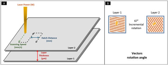
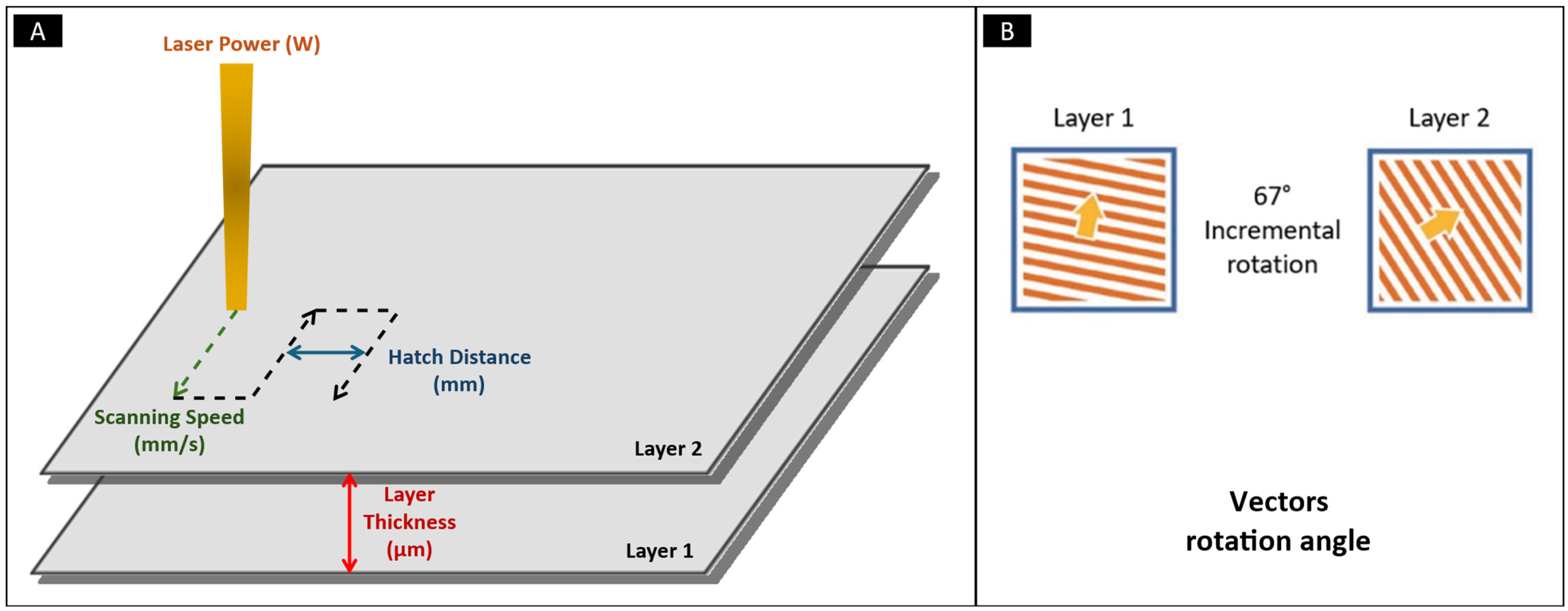
An EOS Eosint M-400 machine (EOS GmbH-EOS EOS GmbH, Krailling, Germany) with a single ytterbium fiber laser was used to create tensile samples. The laser had a wavelength of 1070 nm, a minimum spot size of 80 µm, and a maximum power of 1 KW for all tests. The case study utilizes a C40 steel building platform with the following dimensions: 400 × 400 × 40 mm (thickness). An argon gas flow was continuously pumped inside the building chamber to maintain oxygen content under 100 ppm. The temperature of the building platform was kept constant throughout the building process at 170 °C. We printed all the tested specimens using the process parameters set and the stripes scanning strategy (described in the scheme of Figure 1), which has been widely developed and tested in previous studies on the Hastelloy-X alloy [27], as listed in Table 2.
Figure 1.
Schematic diagram that illustrates the main process parameters for the LPBF process. (A) Laser power, scanning speed, hatch distance, and layer thickness. (B) Illustration of vector rotation angle in the stripes strategy with a suggested incremental rotation value of 67° between two consecutive powder layers.
Table 2.
Process parameters used to manufacture all specimens.
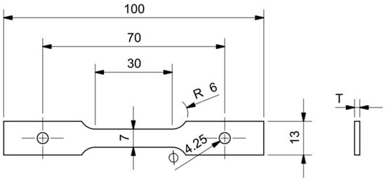
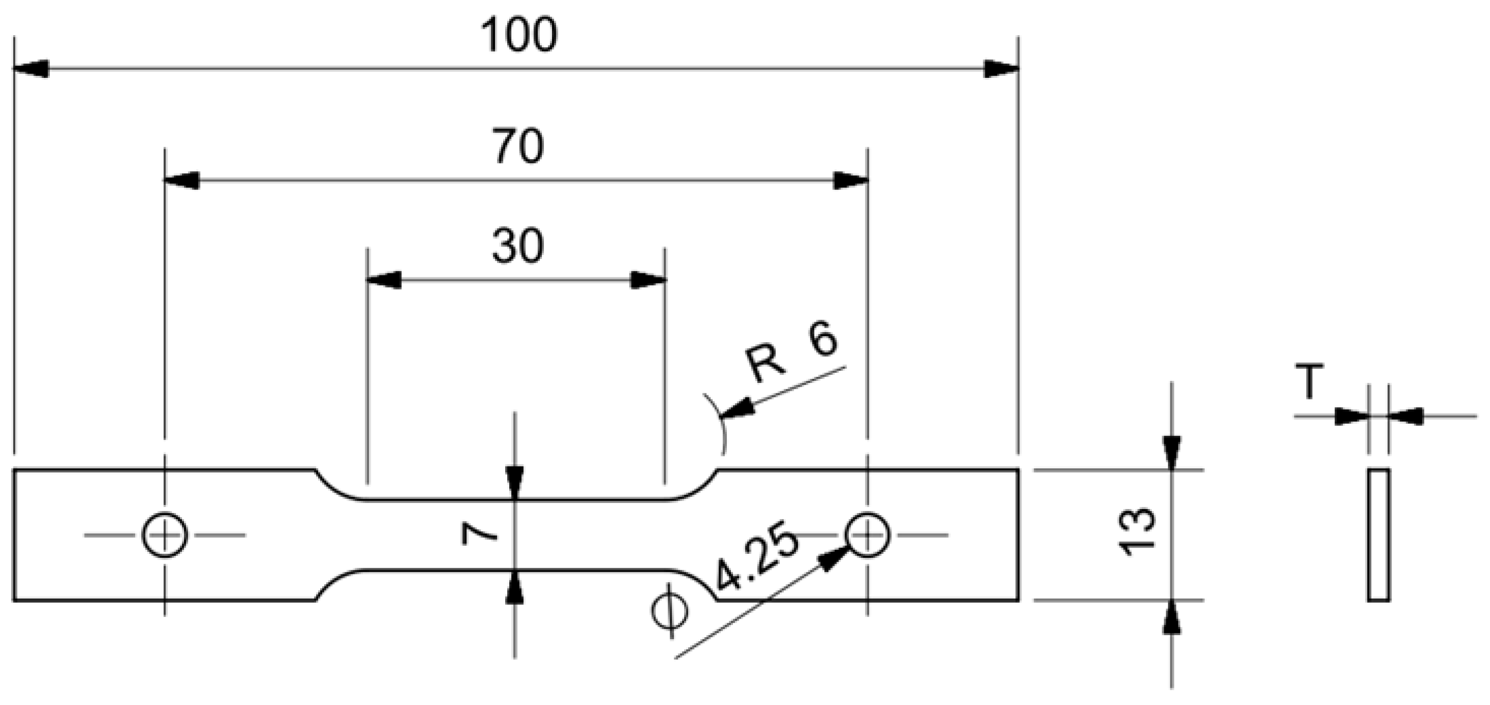
Customized dogbone-shaped specimens were designed in accordance with ASTM E8/E8M-21 [28] (Rectangular Tension Test Specimens—Subsize Specimen), as illustrated in Figure 2. We produced specimens with different wall thicknesses to investigate their mechanical properties as a function of wall thickness. For confidentiality purposes, the specimen wall thickness variation is disclosed in terms of percentage from baseline values, where baseline is indicated as 100%, and the smallest wall thickness is indicated as 40%. The tensile tests were conducted on the fabricated specimens as per the guidelines and specifications provided in ASTM E8/E8M-21 [28]. The standard suggests that the thickness of the specimen must be from 0.13 to 19 mm, which is aligned with this experimental work. The dimensions of the specimens have been scaled in such a manner that the proportions among the ASTM E8/E8M-21 guidelines [28] and the fabricated specimens are kept constant.
Figure 2.
Overview of specimen’s dimensions in mm.
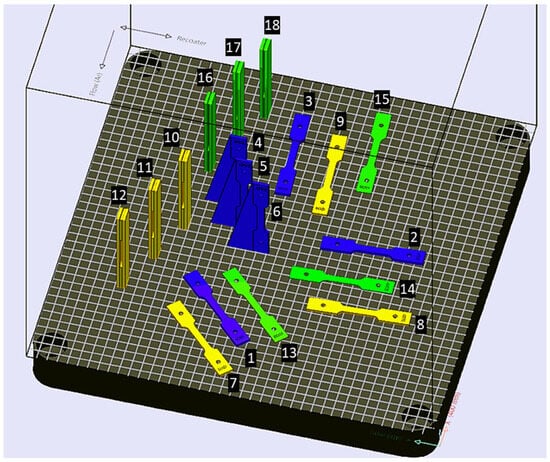
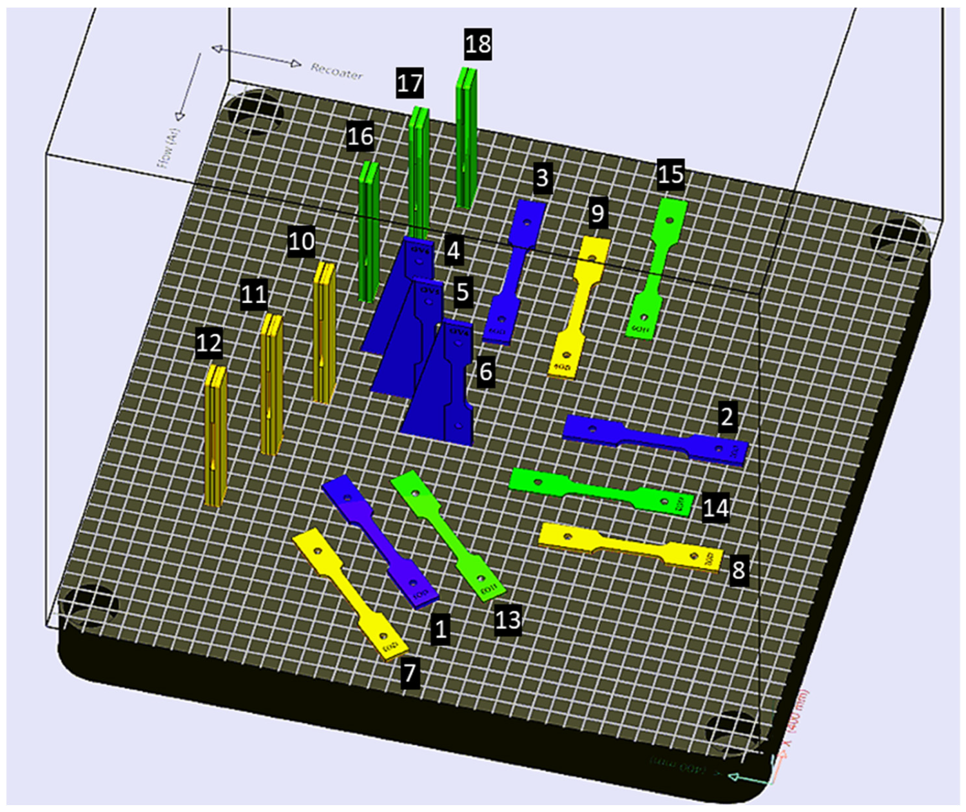
Additionally, we fabricated tensile specimens in both horizontal and vertical orientations to assess the impact of build orientation on the mechanical properties of the material. In order to obtain statistically significant experimental data, three tensile specimens of the same type were fabricated for every wall thickness and printing orientation; thus, a total of 18 specimens were produced. The specimens’ thickness varied from the baseline, indicated as 100% thickness, to 40%, including a middle level of 70%, as is summarized in Table 3. Figure 3 illustrates the building layout and positioning of the specimens on the building platform, and Table 4 reports the list of the configurations tested.
Table 3.
Layer thickness used to manufacture the specimens.
Figure 3.
Job layout of the specimens: baseline purple—thickness 100%, green—thickness 70%, and yellow—thickness 40%.
Table 4.
Specimen tracking table, including number, thickness and building direction.
Upon completion of the specimen production, Wire Electrical Discharge Machining (EDM) was employed to detach the specimens from the building’s platform. Cutting was executed by moving the wire in close proximity to the building platform. After removal from the building platform, all the specimens were solution heat-treated in a vacuum furnace at 1150 °C for 2 h [27]. After heat treatment and before mechanical testing, we measured the specimens’ dimensions using a vernier caliper. The tensile-tested specimens were cautiously cut along the building direction, i.e., along the Z axis for vertical specimens and along the X-Y plane for horizontal ones. The tests were performed following the indication reported in ASTM E8E8M-21 [28]. The specimens were well polished after being embedded in conductive resin to guarantee the effectiveness of the porosity analysis. The porosity analysis was carried out through an optical microscope. Six fields were acquired for each with a magnification factor of 100×. The porosity percentage was then evaluated by processing the acquired images using the commercial tool ImageJ 1.54. Before analyzing the image to evaluate porosity, the binary images were preprocessed to remove dust and scratches that could alter the porosity evaluation.
Microstructural analysis and measurements of porosity were carried out on broken specimens to evaluate the density of the tested specimens and their grain size and morphology. Moreover, to obtain further information about the material’s microstructure, their grain shape and size were evaluated through Electron Back-scatter Diffraction (EBSD) analysis by means of a Field Emission Gun (FEG) SEM Tescan Mira (Tescan, Brno, Czech Republic) on polished and etched specimens. In order to have an acceptable resolution for analysis of the grain morphology, the EBSD analyses were conducted with a magnification of 200× and a step size of 5 microns. The Inverse Pole Figure (IPF) obtained through the EBSD analysis was post-processed using Aztek Crystal 2.0 software to calculate Geometrical Necessary Dislocation (GND) inside the material. The micro-hardness on plane X-Y was evaluated using a Matsuzawa/Via-F automatic Vickers hardness tester (Matsuzawa Co., Ltd., Akita, Japan).
3. Results and Discussion
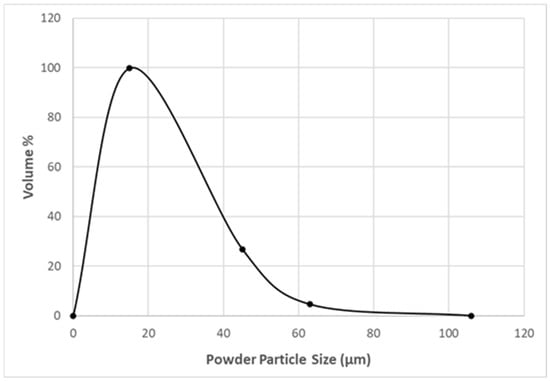
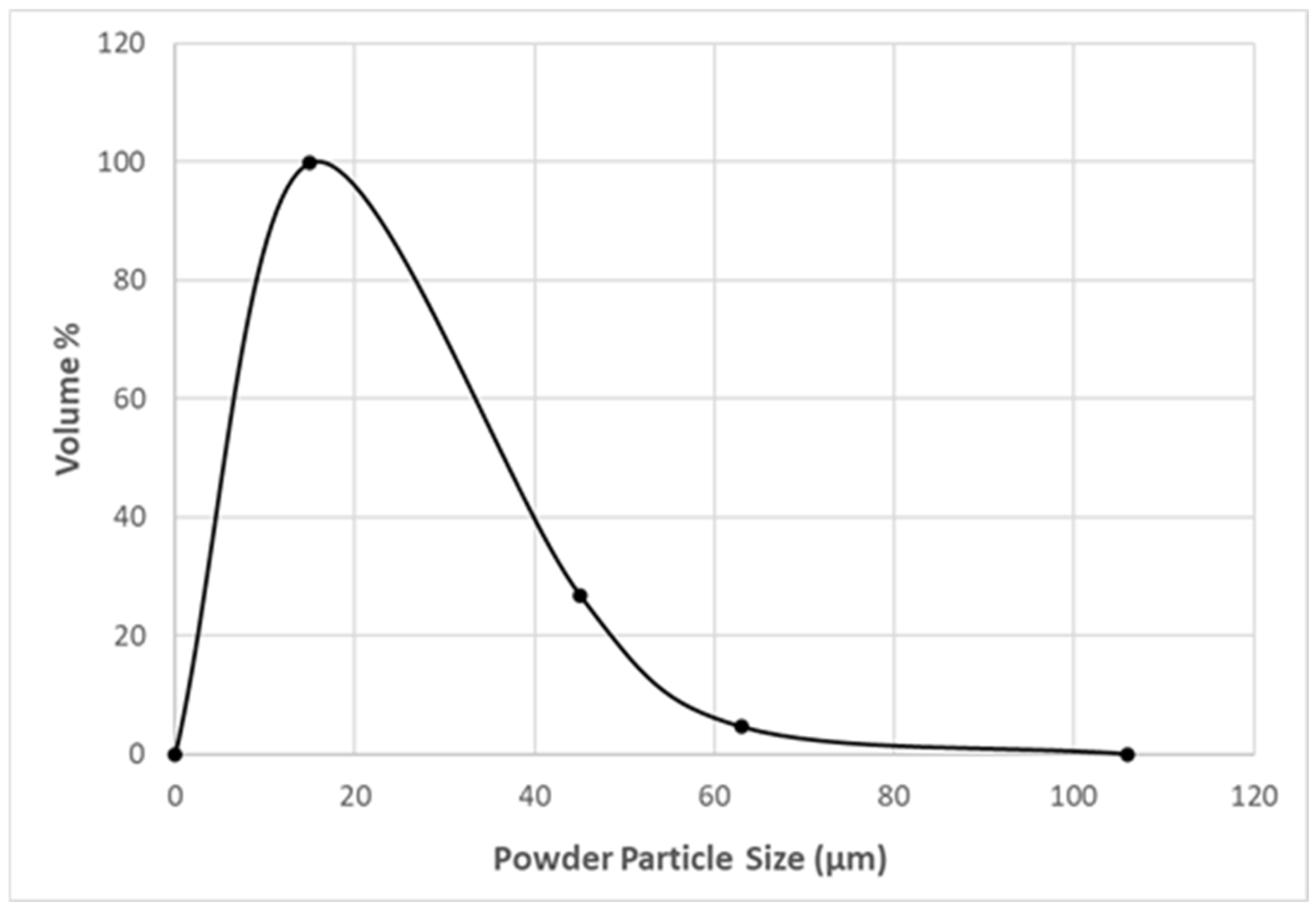
Figure 4 shows that the measured particle size is mostly in the range of 10–70 microns (more than 95% of the powder is within this range). This size is adequate for printing the specimens.
Figure 4.
Particle size distribution.
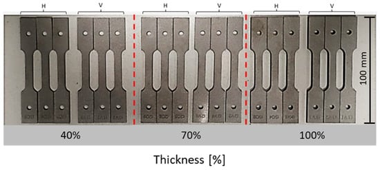
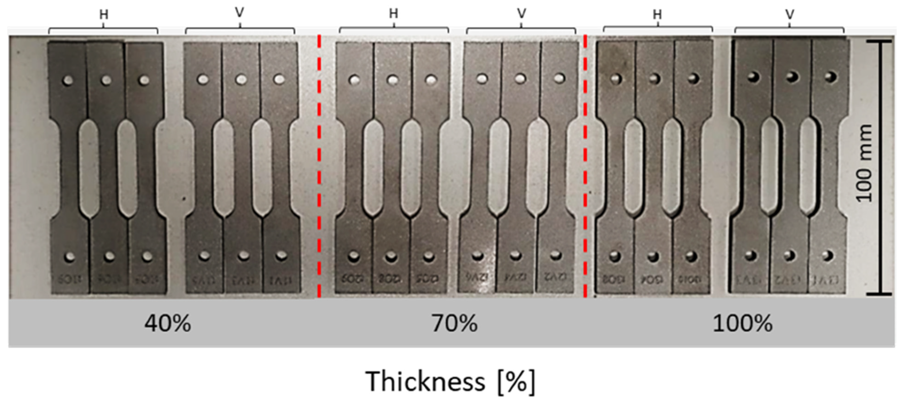
The specimens were printed (Figure 5) using the machine and the process parameters mentioned in Section 2. After heat treatment, the measured thickness values showed no significant variations.
Figure 5.
Printed specimens of various thicknesses used to perform mechanical tests: H (horizontal) and V (vertical).
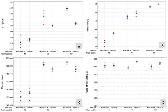
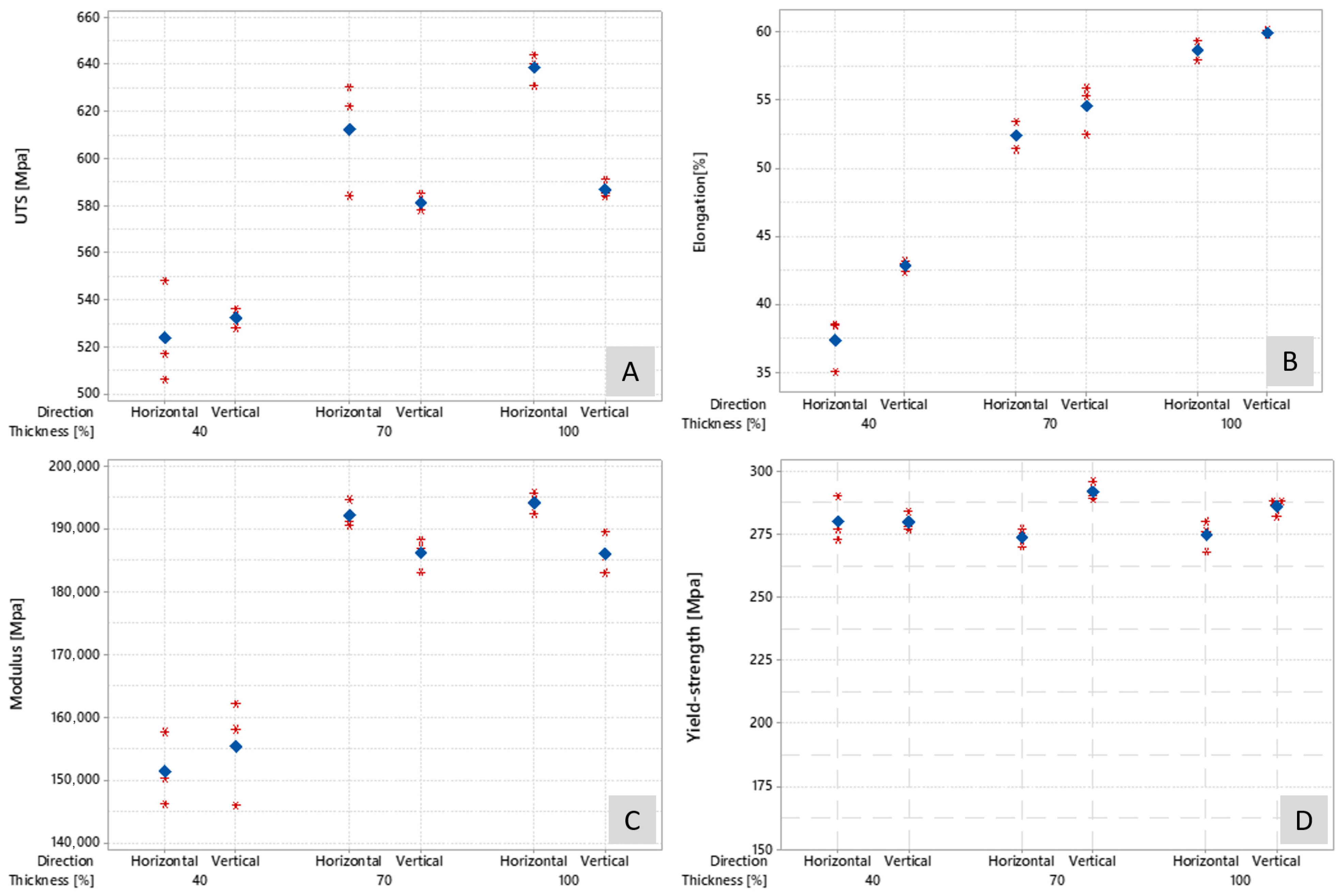
Table 5 reports the results in terms of Yield Strength, UTS, Elongation at Break and Young’s Modulus obtained using the approach described in Section 2. The Individual Plots of the values are represented in Figure 6 according to their different thickness values and printing direction.
Table 5.
Results obtained: UTS, Elongation at Break, Young’s Modulus and Yield Strength.
Figure 6.
Individual plots for UTS (A), Elongation at Break (B), Young’s Modulus (C) and Yield Strength (D). Red asterisks are the single measures; blue rhombi are the mean values.
From Figure 6A, it can be noted that the mean UTS values measured (considering both the horizontal and vertical directions) decrease significantly from 612 MPa at wall thicknesses of 100% and 70% to about 528 MPa at a wall thickness of 40% (about −14%). Considering Elongation at Break (Figure 6B), the effect of the decrease in wall thickness is still significant but appears to depend linearly on the wall thickness value itself; in particular, the decrease in the mean value is about 10% from the reference thickness to 70% (from 59.2% to 40.0%) of the thickness and 32% for the lower thickness (from 190 GPa to 153 GPa). In addition, the analysis of the Young’s Modulus (Figure 6C) reveals an impact of the lower wall thickness on this property, which decreases by about 20% from the values of the other thicknesses.
The data show that the wall thickness and printing direction do not significantly influence the Yield Strength of the material (Figure 6D).
Considering the effect of the building direction on the measured mechanical properties, it is possible to observe a secondary effect with respect to the wall thickness effect, which is still significant, in terms of Elongation at Break (about 6%), UTS (about 4%), Yield Strength (about 3%), and Young’s Modulus values (about 2%).
Table 6 shows a summary of the mean results for the different thicknesses in terms of Yield Strength, UTS and Elongation at Break, and provides a comparison with results from the literature [27] with similar heat-treated conditions but not dogbone-shaped specimens.
Table 6.
Mean value of the mechanical characterization of the configurations with 40% and 100% thickness values printed in vertical and horizontal directions compared with results from the literature (similar heat treatment conditions).
Although the specimens are geometrically and dimensionally very challenging (dogbone specimens, as-built surface conditions), the mechanical performance achieved for the 100% thickness specimens is slightly lower (about 10%) than the performance obtained in the literature for cylindrical specimens in similar heat treatment conditions [29]. Considering the other references, it can be observed that higher temperatures during heat treatment lead to greater resistance and lower elongation (Huang et al. [30]), and this can be balanced by extending the duration of the heat treatment, as shown by Keshavarzkermani et al. [31]. On the other hand, the mechanical performance of lower-thickness specimens shows a significant gradual reduction from the baseline [29], particularly the UTS and Elongation values.
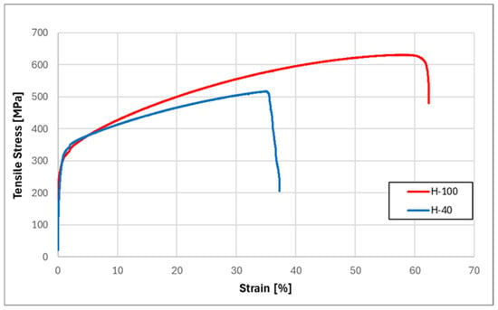
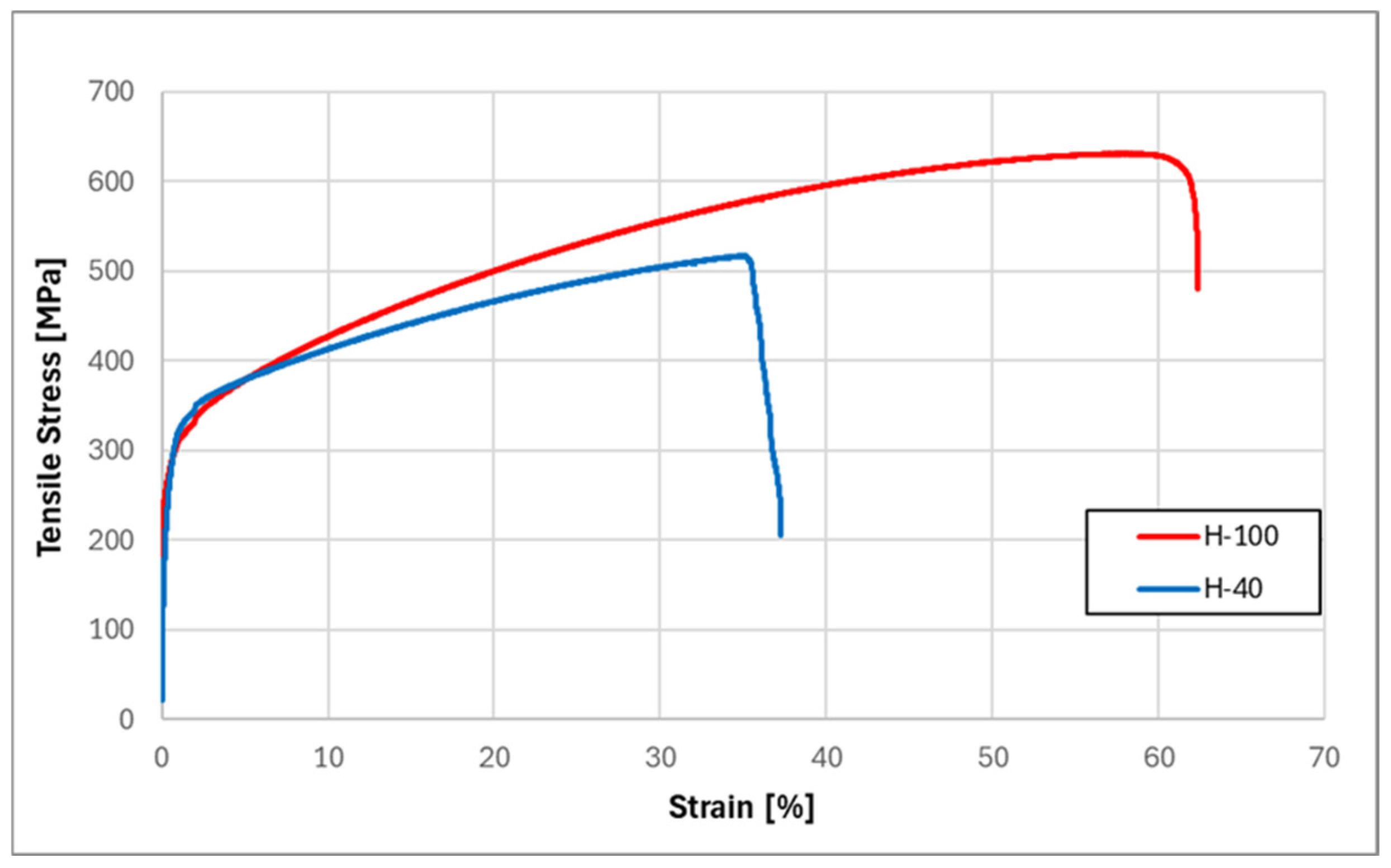
In order to provide a more qualitative comparison of the effects of the wall thickness in a stress–strain plot, the two curves corresponding to the highest and lowest wall thickness levels (numbers 3 and 13, respectively) are reported in Figure 7. Their curves are similar in shape, but there is a noticeable difference in terms of reduction in the Elongation at Break and UTS values.
Figure 7.
Raw plot of mechanical properties extracted from the tensile machine software for specimen #13 (thickness 40%) and #3 (thickness 100%).
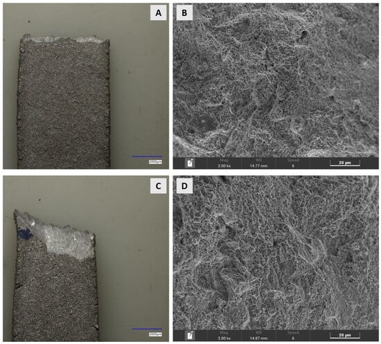
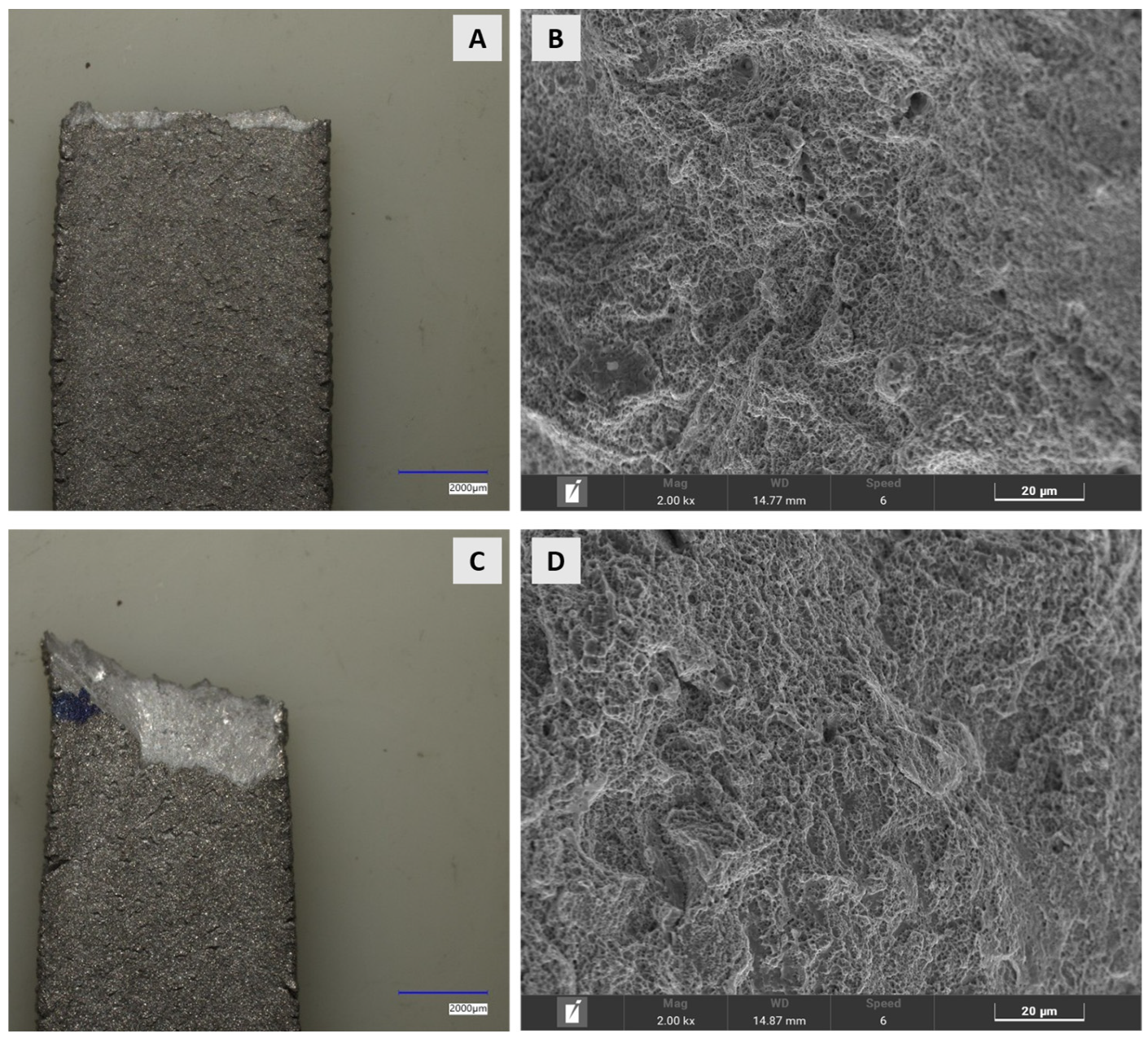
The fracture surfaces of the same specimens are shown in Figure 8A,B, highlighting the presence of necking only for specimen 3 (thickness 100%). This physical evidence could be related to the higher elongation measured in the 100% thickness specimens. Through the evaluation of the micrographic images in Figure 8B,D of fracture surfaces acquired by SEM, the widespread Dimple features are remarkable, in both cases indicating the ductile behavior of the material’s fracture.
Figure 8.
Fracture surfaces of the specimens: optical overview of surface fracture on the left and SEM micrographic analysis on the right. Images (A,B) are referred to as specimen #13 (thickness 40%), and images (C,D) are referred to as specimen #3 (thickness 100%).
To investigate the variations in mechanical properties based on the build orientation of the specimens, microstructural analyses were performed on both vertically and horizontally built tensile specimens.
The measured porosity percentage for each specimen is listed in Table 7.
Table 7.
Porosity analysis tracking table: Mean = 0.032%, Standard Dev = 0.010%.
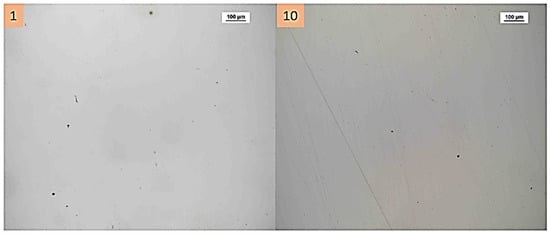
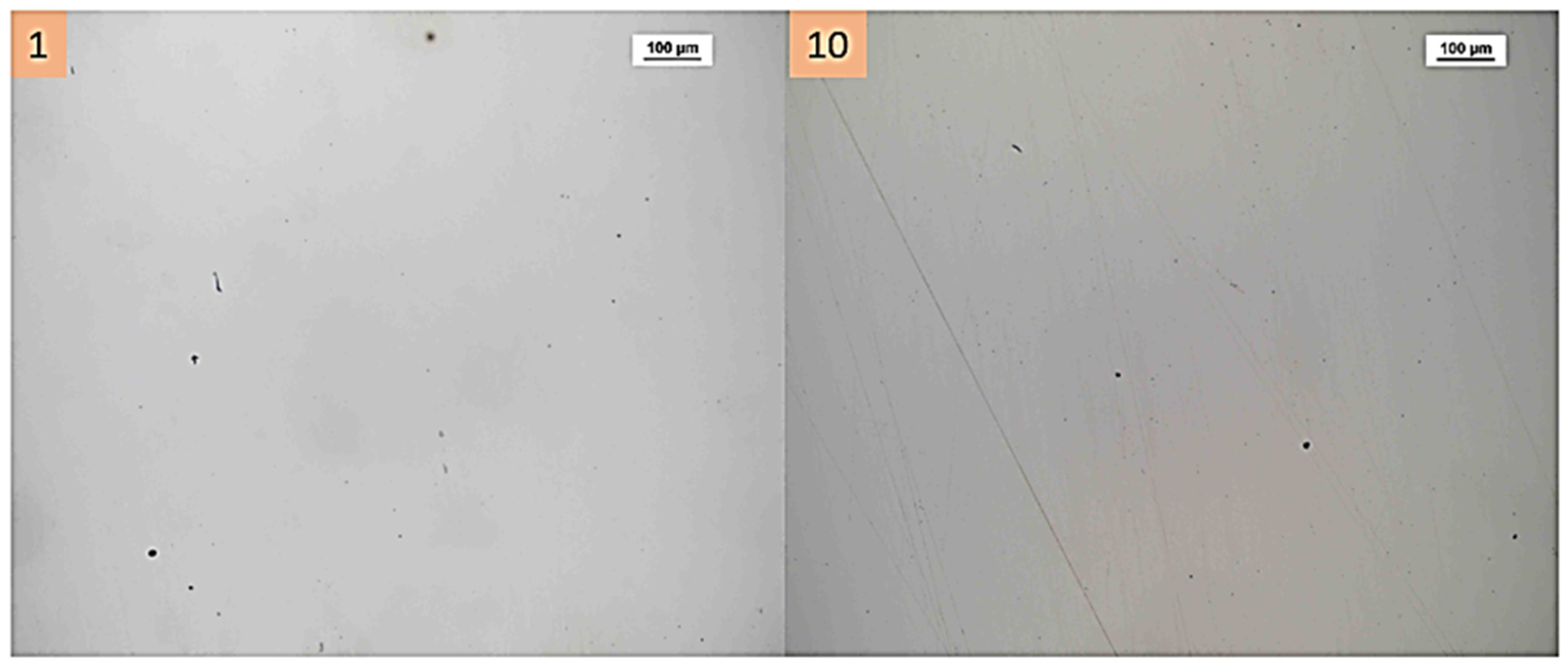
Based on the results listed in Table 7, there is no significant influence of thickness and printing direction on porosity. The porosity value measured for each analyzed specimen is low, and consequently, the material could be considered fully dense, as shown in Figure 9.
Figure 9.
Material microstructure images acquired using an Optical Microscope for specimen #1 (on the left side) and #10 (on the right side). Evaluating these pictures shows the fully dense condition of the material.
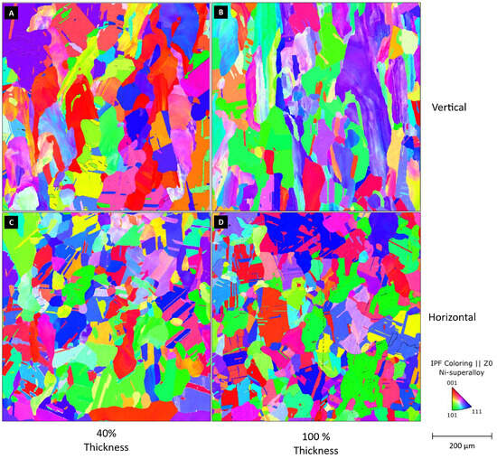
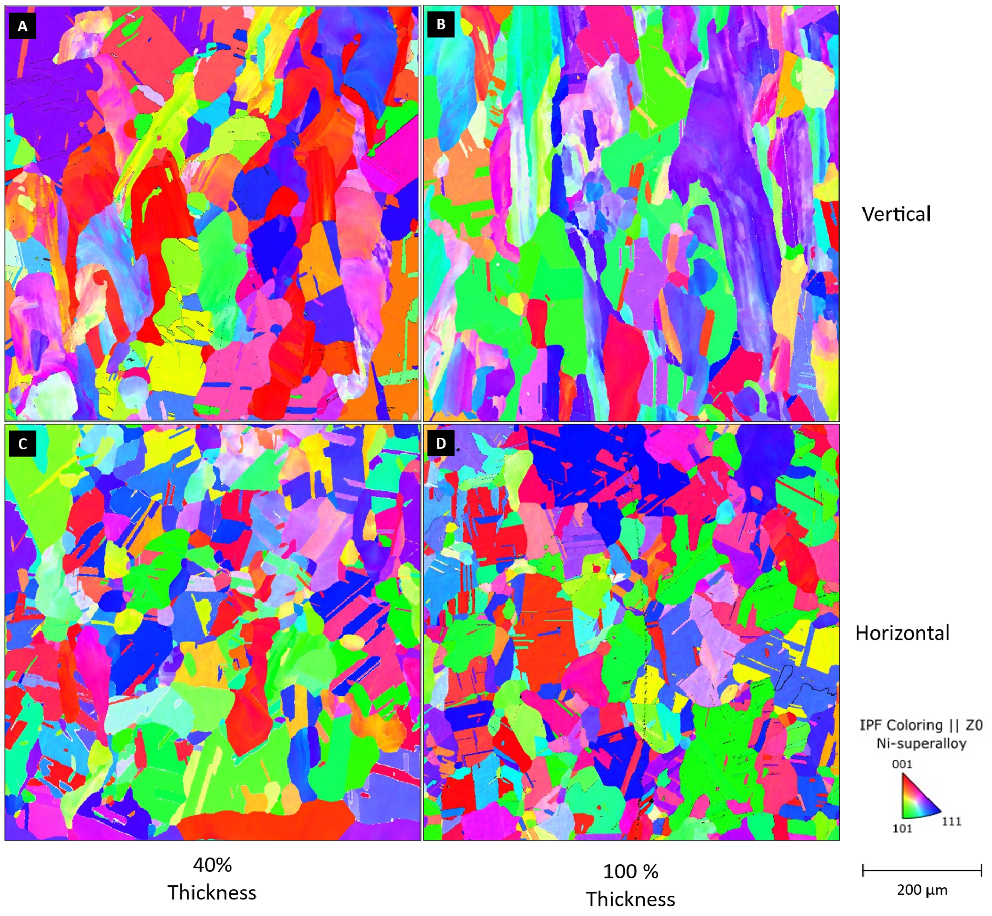
Figure 10 illustrates the grain size and morphology of the material of the horizontal and vertical specimens. All images were obtained using a cross-section of the specimens along the printing direction.
Figure 10.
Grain analysis, in terms of size and shape: (A) Specimen 16 (Thickness 40%, Vertical); (B) Specimen 6 (Thickness 100%, Vertical); (C) Specimen 13 (Thickness 40%, Horizontal); (D) Specimen 3 (Thickness 100%, Horizontal).
Through the evaluation of the IPF images presented in Figure 10, it is possible to remark on how the vertical specimens (Figure 10A,B) are characterized by a columnar texture, similar to the microstructure typical of the not-heat-treated condition. On the other hand, the horizontal specimens (Figure 10C,D) have a quite equiaxial texture. In addition, considering the values measured for the Geometrical Necessary Dislocation (GND) (Table 8), it is possible to observe how vertical specimens are characterized by higher values, about 40% more, compared to horizontal ones. By virtue of all these results, it could be hypothesized that part of the residual stresses accumulated during the printing process for the horizontal specimens has been used as a driving force [27] to promote grain rearrangement during the heat treatment process. In contrast, for vertical specimens, hypothetically lower values of residual stresses, which were produced during the printing process, might not have been able to provide sufficient energy to activate the recrystallization process during the heat treatment of the material.
Table 8.
Overview of the measured values of GND.
By virtue of all the previous considerations, as the same volumetric energy density (VED) was used for both the vertical and horizontal printed specimens, these, according to the experimental results obtained by Deirmina et al. [27], should provide (considering the same heat treatment conditions) a material with the same degree of recrystallization.
Despite this, the results obtained in this work, as previously mentioned, show marked microstructural differences between the analyzed specimens exposed to the same process parameters (i.e., same energy density). In fact, the vertical specimens show partial recrystallization (Figure 10A,B), while the horizontal specimens appear more recrystallized (Figure 10C,D). Consequently, the degree of recrystallization in an LPBF-made material, after heat treatment, may depend not only on the VED used during the printing process but also on the amount of area exposed per layer, which in this case study is much greater for horizontal specimens than for vertical ones (Figure 3). This variation in terms of recrystallization level could find its physical explanation in a lower residual stress being formed in vertical specimens than in horizontal ones after the LPBF process, according to by Deirmina et al. [27]. In addition, as demonstrated in a previous study by Baldi et al. [32], the building platform’s preheating temperature could affect the microstructure of the material of the horizontal specimens, particularly for the specimens with the lowest thickness (40%).
Through the evaluation of the Microhardness results shown in Table 8, it is noteworthy that the specimens with lower thickness, regardless of the building direction, exhibit lower values (about 8% less) than the specimens fabricated with higher thickness values. These results are in accordance with the measured values of UTS, which are lower for the specimens with 40% thickness. On the other hand, the behavior of the material, concerning the low values of Elongation at Break exhibited in the 40% thickness specimens, was not justified by the set of microstructural and Microhardness analyses that were carried out.
4. Conclusions
The study’s results indicate that the thickness of a specimen made of Hastelloy-X alloy, produced by LPBF, and heat-treated in a vacuum furnace at 1150 °C for 2 h, could influence the degradation of its mechanical properties at room temperature.
In particular:
- UTS decreases by about 14% from 100% to 40% thickness (from 612 MPa for the 3 mm thickness to 528 MPa for the 1 mm thickness).
- Elongation at Break depends linearly on wall thickness and decreases about 32% in the thickness range tested (from 59.2% to 40.0%);
- Lower thickness specimens have a Young’s Modulus that is lower by about 19.3% with respect to specimens of 100% thickness (from 190 GPa to 153 GPa);
- The building direction has a lower impact, though still statistically significant, on mechanical properties.
From a microstructural point of view, all the thicknesses tested resulted in fully dense specimens, and the EBSD analyses revealed a remarkable difference in terms of residual stress accumulation inside the materials (evaluated through a GND analysis) and, consequently, of recrystallization levels as a function of the building direction tested. The Microhardness measurements are in accordance with the results retrieved for UTS.
The overall results suggest that under specific geometric and process conditions, such as the presence of a thin exposed wall with a striped pattern, the application of the normally used heat treatment may not be sufficient to achieve the desired mechanical performance for the material. In particular, the observed degradation of mechanical properties permits the identification of a critical thickness value of about 1 mm for the as-built surface condition and the heat treatment tested in this paper.
In future work, it will be useful to perform tests at high temperatures to confirm the results retrieved here at room temperature.
Author Contributions
Conceptualization, N.B., A.G., L.C., G.C., G.A., P.C. and M.M.; methodology, N.B., A.G. and L.C.; software, A.G.; validation, L.C.; formal analysis, N.B.; investigation, N.B., A.G. and L.C.; resources, G.C., G.A., P.C. and M.M.; data curation, N.B. and A.G.; writing—original draft preparation, N.B., A.G. and L.C.; writing—review and editing, N.B., A.G., L.C., G.C., G.A., P.C. and M.M.; visualization, N.B., A.G. and L.C.; supervision, G.A. and P.C.; project administration, G.C. and M.M.; funding acquisition, L.C. All authors have read and agreed to the published version of the manuscript.
Funding
This research received no external funding.
Data Availability Statement
Summarized data are contained within the article. The raw data are available on request from the corresponding author after obtaining the permission of Baker Hughes, Nuovo Pignone.
Conflicts of Interest
The authors declare the following financial interests/personal relationships which may be considered potential competing interests: Niccolo Baldi, Giulio Carcasci, Lokesh Chandrabalan and Marco Manetti report a relationship with Baker Hughes—Nuovo Pignone that includes employment. The other authors declare that they have no known competing financial interests or personal relationships that could have appeared to influence the work reported in this paper.
References
- Wang, P.; Song, J.; Nai, M.L.S.; Wei, J. Experimental analysis of additively manufactured component and design guidelines for lightweight structures: A case study using electron beam melting. Addit. Manuf. 2020, 33, 101088. [Google Scholar] [CrossRef] [Scilit]
- Amicarelli, M.; Trovato, M.; Cicconi, P. Lightweight Design of a Connecting Rod Using Lattice-Structure Parameter Optimisation: A Test Case for L-PBF. Machines 2025, 13, 171. [Google Scholar] [CrossRef] [Scilit]
- Giorgetti, A.; Rolli, F.; La Battaglia, V.; Marini, S.; Arcidiacono, G. Axiomatic design using multi-criteria decision making for material selection in mechanical design: Application in different scenarios. In International Conference on Axiomatic Design; Lecture Notes in Networks and Systems; Springer Nature: Cham, Switzerland, 2023; pp. 135–148. [Google Scholar] [CrossRef] [Scilit]
- Blakey-Milner, B.; Gradl, P.; Snedden, G.; Brooks, M.; Pitot, J.; Lopez, E.; Leary, M.; Berto, F.; Du Plessis, A. Metal additive manufacturing in aerospace: A review. Mater. Des. 2021, 209, 110008. [Google Scholar] [CrossRef] [Scilit]
- Amano, H.; Ishimoto, T.; Hagihara, K.; Suganuma, R.; Aiba, K.; Sun, S.-H.; Wang, P.; Nakano, T. Impact of gas flow direction on the crystallographic texture evolution in laser beam powder bed fusion. Virtual Phys. Prototyp. 2023, 18, e2169172. [Google Scholar] [CrossRef] [Scilit]
- Wang, Z.; Guan, K.; Gao, M.; Li, X.; Chen, X.; Zeng, X. The microstructure and mechanical properties of deposited-IN718 by selective laser melting. J. Alloys Compd. 2011, 513, 518–523. [Google Scholar] [CrossRef] [Scilit]
- Das, S. Physical aspects of process control in selective laser sintering of metals. Adv. Eng. Mater. 2003, 5, 701–711. [Google Scholar] [CrossRef] [Scilit]
- Osakada, K.; Shiomi, M. Flexible manufacturing of metallic products by selective laser melting of powder. Int. J. Mach. Tools Manuf. 2006, 46, 1188–1193. [Google Scholar] [CrossRef] [Scilit]
- Gottipati, U.N.; Minotti, A.; La Battaglia, V.; Giorgetti, A. Design Challenges in the Development of a Hydrogen-Fueled Micro Gas Turbine Unit for Energy Generation. Eng. Proc. 2025, 85, 45. [Google Scholar] [CrossRef] [Scilit]
- Kruth, J.; Mercelis, P.; Van Vaerenbergh, J.; Froyen, L.; Rombouts, M. Binding mechanisms in selective laser sintering and selective laser melting. Rapid Prototyp. J. 2005, 11, 26–36. [Google Scholar] [CrossRef] [Scilit]
- Yadroitsev, I.; Gusarov, A.; Yadroitsava, I.; Smurov, I. Single track formation in selective laser melting of metal powders. J. Mater. Process. Technol. 2010, 210, 1624–1631. [Google Scholar] [CrossRef] [Scilit]
- Dejene, N.D.; Lemu, H.G. Current Status and Challenges of Powder Bed Fusion-Based Metal Additive Manufacturing: Literature Review. Metals 2023, 13, 424. [Google Scholar] [CrossRef] [Scilit]
- Gibson, I.; Rosen, D.; Stucker, B. Additive Manufacturing Technologies; Springer: Cham, Switzerland, 2014. [Google Scholar] [CrossRef] [Scilit]
- Giorgetti, A.; Baldi, N.; Palladino, M.; Ceccanti, F.; Arcidiacono, G.; Citti, P. A method to optimize parameters development in L-PBF based on single and multitracks analysis: A case study on Inconel 718 Alloy. Metals 2023, 13, 306. [Google Scholar] [CrossRef] [Scilit]
- Mahmoud, D.; Magolon, M.; Boer, J.; Elbestawi, M.A.; Mohammadi, M.G. Applications of Machine Learning in Process monitoring and Controls of L-PBF Additive Manufacturing: A review. Appl. Sci. 2021, 11, 11910. [Google Scholar] [CrossRef] [Scilit]
- Dudzinski, D.; Devillez, A.; Moufki, A.; Larrouquère, D.; Zerrouki, V.; Vigneau, J. A review of developments towards dry and high speed machining of Inconel 718 alloy. Int. J. Mach. Tools Manuf. 2003, 44, 439–456. [Google Scholar] [CrossRef] [Scilit]
- Makoana, N.W.; Moller, H.; Burger, H.; Tlotleng, M.; Yadroitsev, I. Evaluation of single tracks of 17-4PH steel manufactured at different power densities and scanning speeds by selective laser melting. S. Afr. J. Ind. Eng. 2016, 27, 210–218. [Google Scholar] [CrossRef] [Scilit]
- Liu, X.; Wang, K.; Hu, P.; He, X.; Yan, B.; Zhao, X. Formability, microstructure and properties of Inconel 718 Superalloy fabricated by selective laser melting Additive manufacture technology. Materials 2021, 14, 991. [Google Scholar] [CrossRef] [Scilit]
- DebRoy, T.; Wei, H.L.; Zuback, J.S.; Mukherjee, T.; Elmer, J.W.; Milewski, J.O.; Beese, A.M.; Wilson-Heid, A.; De, A.; Zhang, W. Additive manufacturing of metallic components—Process, structure and properties. Prog. Mater. Sci. 2017, 92, 112–224. [Google Scholar] [CrossRef] [Scilit]
- Yu, C.-H.; Peng, R.L.; Luzin, V.; Sprengel, M.; Calmunger, M.; Lundgren, J.-E.; Brodin, H.; Kromm, A.; Moverare, J. Thin-wall effects and anisotropic deformation mechanisms of an additively manufactured Ni-based superalloy. Addit. Manuf. 2020, 36, 101672. [Google Scholar] [CrossRef] [Scilit]
- King, W.E.; Anderson, A.T.; Ferencz, R.M.; Hodge, N.E.; Kamath, C.; Khairallah, S.A.; Rubenchik, A.M. Laser powder bed fusion additive manufacturing of metals; physics, computational, and materials challenges. Appl. Phys. Rev. 2015, 2, 041304. [Google Scholar] [CrossRef] [Scilit]
- Yadroitsev, I.; Yadroitsava, I.; Bertrand, P.; Smurov, I. Factor analysis of selective laser melting process parameters and geometrical characteristics of synthesized single tracks. Rapid Prototyp. J. 2012, 18, 201–208. [Google Scholar] [CrossRef] [Scilit]
- Thompson, M.K.; Moroni, G.; Vaneker, T.; Fadel, G.; Campbell, R.I.; Gibson, I.; Bernard, A.; Schulz, J.; Graf, P.; Ahuja, B.; et al. Design for Additive Manufacturing: Trends, opportunities, considerations, and constraints. CIRP Ann. 2016, 65, 737–760. [Google Scholar] [CrossRef] [Scilit]
- Vu, H.M.; Meiniger, S.; Ringel, B.; Hoche, H.C.; Oechsner, M.; Weigold, M.; Schmitt, M.; Schlick, G. Investigation of Material Properties of Wall Structures from Stainless Steel 316L Manufactured by Laser Powder Bed Fusion. Metals 2022, 12, 285. [Google Scholar] [CrossRef] [Scilit]
- Zhang, Y.; Majeed, A.; Muzamil, M.; Lv, J.; Peng, T.; Patel, V. Investigation for macro mechanical behavior explicitly for thin-walled parts of AlSi10Mg alloy using selective laser melting technique. J. Manuf. Process. 2021, 66, 269–280. [Google Scholar] [CrossRef] [Scilit]
- Cai, G.; Liu, H.; Peng, K.; Wang, B.; Hu, B. Orthogonal experimental method to investigate the effect of process parameters on the mechanical properties of thin-walled parts by LPBF. Sci. Rep. 2024, 14, 19776. [Google Scholar] [CrossRef] [Scilit]
- Deirmina, F.; Adegoke, O.; Del Col, M.; Pellizzari, M. Effect of layer thickness, and laser energy density on the recrystallization behavior of additively manufactured Hastelloy X by laser powder bed fusion. Addit. Manuf. Lett. 2023, 7, 100182. [Google Scholar] [CrossRef] [Scilit]
- ASTM E8/E8M-21; Standard Test Methods for Tension Testing of Metallic Materials. ASTM International: West Conshohocken, PA, USA, 2014.
- Cheng, X.; Du, Z.; Chu, S.; Wu, J.; Dong, J.; Wang, H.; Ma, Z. The effect of subsequent heating treatment on the microstructure and mechanical properties of additive manufactured Hastelloy X alloy. Mater. Charact. 2022, 186, 111799. [Google Scholar] [CrossRef] [Scilit]
- Huang, R.; Sun, Y.; Tan, C.; Lin, D.; Song, X.; Zhao, H. Investigation of microstructure and failure mechanisms at room and elevated temperature of Hastelloy X produced by laser powder-bed fusion. Next Mater. 2024, 2, 100142. [Google Scholar] [CrossRef] [Scilit]
- Keshavarzkermani, A.; Esmaeilizadeh, R.; Enrique, P.D.; Asgari, H.; Zhou, N.Y.; Bonakdar, A.; Toyserkani, E. Static recrystallization impact on grain structure and mechanical properties of heat-treated Hastelloy X produced via laser powder-bed fusion. Mater. Charact. 2021, 173, 110969. [Google Scholar] [CrossRef] [Scilit]
- Baldi, N.; Giorgetti, A.; Palladino, M.; Giovannetti, I.; Arcidiacono, G.; Citti, P. Study on the Effect of Preheating Temperatures on Melt Pool Stability in Inconel 718 Components Processed by Laser Powder Bed Fusion. Metals 2023, 13, 1792. [Google Scholar] [CrossRef] [Scilit]

Disclaimer/Publisher’s Note: The statements, opinions and data contained in all publications are solely those of the individual author(s) and contributor(s) and not of MDPI and/or the editor(s). MDPI and/or the editor(s) disclaim responsibility for any injury to people or property resulting from any ideas, methods, instructions or products referred to in the content. |
© 2026 by the authors. Licensee MDPI, Basel, Switzerland. This article is an open access article distributed under the terms and conditions of the Creative Commons Attribution (CC BY) license.