


Abstract
To address the trade-off between macroscopic stroke and high stiffness in XY precision positioning, this study proposes a platform utilizing a Connecting Arm and Guide Rail Integration decoupling mechanism. Distinct from traditional suspended-mover or flexure-based schemes, this design integrates precision guiding directly into a rigid connecting arm to mechanically isolate parasitic motion. Finite Element Analysis confirms a safety margin with a maximum equivalent stress of 8.34 MPa. Notably, the platform achieves a first-order natural frequency of 864.82 Hz, which is significantly higher than the Voice Coil Motor’s actuation frequency, effectively mitigating low-frequency resonance. Transient dynamic analysis further suggests that the mechanism suppresses cross-axis interference to the sub-nanometer level (0.61 nm) during high-acceleration maneuvers. Experimental validation demonstrates favorable tracking capabilities: for a 5 mm step motion, the positioning deviation is controlled within 0.005 mm. These findings suggest that the proposed solution offers a feasible and competitive approach for high-stiffness precision positioning applications.
1. Introduction
In high-end manufacturing fields such as microelectronic packaging, chip bonding, and high-precision assembly, the XY precision positioning platform serves as a critical executive unit, its dynamic performance and positioning accuracy directly determine the ultimate throughput and yield of the equipment [1,2,3]. As cross-scale manufacturing processes evolve towards higher integration and broader operational ranges, next-generation positioning systems face increasingly stringent and often conflicting comprehensive performance requirements. Ideally, such systems must achieve a millimeter-level or even longer macro-stroke to cover extensive workspaces, while simultaneously maintaining nanometer-level positioning resolution, minimal low cross-axis coupling errors and sufficient structural stiffness to suppress residual vibrations during high-speed motion. However, achieving a balance between large stroke, high stiffness, and high decoupling performance within a single system remains a challenge in precision engineering [4].
To address the precision demands of micro-nano manipulation, flexure-based compliant mechanisms have been extensively investigated due to their inherent advantages of being friction-free, backlash-free, and maintenance-free [5]. Nevertheless, the intrinsic micrometer-level stroke limitation of piezoelectric actuators restricts their application in large-range tasks. To overcome this bottleneck, researchers have developed various displacement amplification strategies [6]. For instance, the novel Z-shaped flexure hinges proposed recently by Gan et al. [7] and the bridge-type amplification mechanisms designed by Dong et al. [8] have successfully utilized geometric leverage principles to extend the workspace to the order of several hundred micrometers or even the sub-millimeter range, significantly outperforming traditional direct-drive flexure stages [9]. Concurrently, to mitigate cross-coupling in multi-axis motion, Tian et al. [10] and Huang et al. [11] have further enhanced the motion independence of such platforms by optimizing parallelogram mechanisms and compound flexure modules [12,13]. Despite these advancements, compliant amplification mechanisms are fundamentally constrained by the inverse relationship between stroke and stiffness: substantial displacement amplification is often achieved at the expense of system rigidity and resonant frequency. Furthermore, under large deformation conditions, flexure elements are prone to non-linear parasitic motions and drift [14,15,16,17], making it difficult for such mechanisms to break through the millimeter-scale stroke barrier while maintaining high-frequency dynamic servo characteristics.
In contrast, rigid drive schemes based on voice coil motors (VCM) have emerged as another mainstream alternative for achieving long-stroke precision motion, owing to their high thrust density, fast response, and theoretically infinite stroke. Recent research has primarily focused on enhancing the performance density of the motor itself. For example, Zhang et al. [18] and Kang et al. [19] have significantly improved thrust fluctuation and thermal characteristics through coreless flat-type structure optimization and miniaturized designs, respectively. However, when integrating VCMs into multi-degree-of-freedom XY platforms, eliminating inter-axis coupling remains a core obstacle. Although Ahn et al. [20,21] explored magnetic levitation technologies to effectively eliminate friction and coupling disturbances, these solutions typically result in highly complex control systems, bulky volumes, and prohibitive costs, hindering their widespread adoption in cost-sensitive industrial scenarios.
Regarding rigid mechanical decoupling, another common existing strategy is mover decoupling, which involves redesigning the motor mover or introducing intermediate sliders to allow for free motion within the plane [22,23]. While this approach achieves motion separation to some extent, it often forces the mover to adopt slender, thin-walled structures or complex suspended connections to minimize moving mass and accommodate multi-directional movement. Such structural configurations often compromise the local stiffness of the kinematic chain, leading to a reduction in the overall system modal frequency, thereby limiting the control bandwidth and disturbance rejection capability. Consequently, there is a notable absence of a mechanical solution that is structurally compact, cost-effective, and capable of effectively resolving rigid transmission coupling issues without sacrificing structural stiffness.
Addressing this research gap, this study proposes an XY precision positioning platform based on a connecting arm and guide rail integrated decoupling mechanism. To overcome the trade-off limitations among stroke, stiffness, and decoupling performance found in traditional designs, this study integrates the precision guiding function directly within the rigid connecting arm structure. This compact, modular configuration introduces clear physical constraints, enabling the platform to mechanically isolate the transmission path of parasitic motion and significantly reduce cross-axis coupling while achieving millimeter-level large-stroke direct drive. More importantly, this design abandons the fragile slender structures typical of traditional mover decoupling, leveraging its enhanced closed-loop structural stiffness to effectively avoid the low-frequency resonance phenomena common in long-stroke mechanisms. Through detailed static modeling, finite element analysis, and experimental prototype verification, this study aims to demonstrate that the proposed platform successfully strikes a favorable balance between macro-stroke, high natural frequency, and low coupling error, offering a competitive and cost-effective new solution for high-performance precision positioning equipment.
2. Overall Platform Structure Analysis
2.1. Voice Coil Motor (Actuation) Analysis
The platform is driven by a Voice Coil Motor (VCM). VCMs directly convert electrical energy into linear or limited angular mechanical motion without intermediate transmission mechanisms like gears or belts, offering high response speed, high precision, and direct drive characteristics [24].
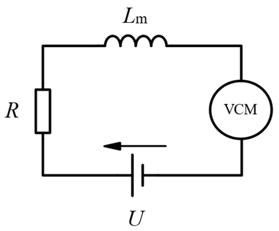
Figure 1 shows the working circuit schematic of a voice coil motor. Analysis [25] yields the expression for the theoretical actuation frequency of a VCM under ideal conditions, as shown in Equation (1):
where is the force constant of the VCM (force-to-current ratio), is the back electromotive force (Back-EMF) constant. The Back-EMF constant is theoretically equal to the force constant in SI units (), is the moving mass of the VCM (mover mass), and is the coil inductance. This study utilizes a linear cylindrical VCM, model TMEC 0330-035-000 from Tong Mao Motor (Kunshan, China). Specific parameters are listed in Table 1.
Figure 1.
Working circuit diagram of voice coil motor.
Table 1.
Voice Coil Motor Parameters.
Calculation based on these parameters yields an actuation frequency of 89.35 Hz for the employed VCM.
2.2. Platform Structure Analysis
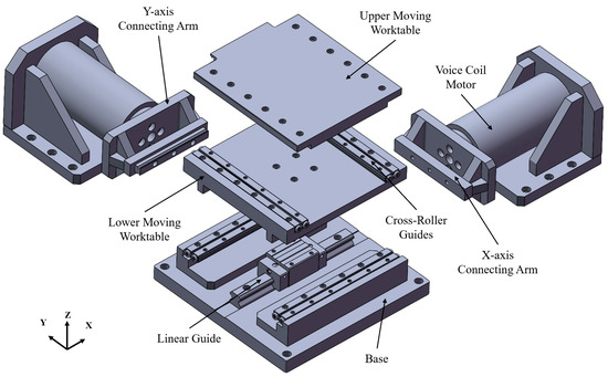
The overall mechanical configuration of the proposed XY precision positioning platform is illustrated in Figure 2. The system adopts a compact, modular design primarily composed of a fixed base, two orthogonal Voice Coil Motor (VCM) actuators, two sets of connecting arm assemblies, and a central motion stage. To achieve high-precision planar motion, the motion stage utilizes a stacked architecture, divided into a Lower Moving Worktable and an Upper Moving Worktable. The Lower Moving Worktable is constrained by guide rails mounted on the base, limiting its movement exclusively to the X-axis. The Upper Moving Worktable is stacked atop the Lower Moving Worktable via intermediate cross-roller guides, enabling relative motion along the Y-axis. This hierarchical arrangement ensures that the X-axis actuation unit drives the entire stack, while the Y-axis unit independently actuates the top layer. To facilitate direct drive transmission, the connecting arms are rigidly attached to the VCM movers, serving as the primary mechanical links that convert electromagnetic thrust into linear displacement without intermediate gears or belts.
Figure 2.
Overall structure diagram of the platform.
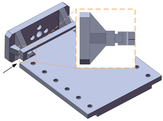
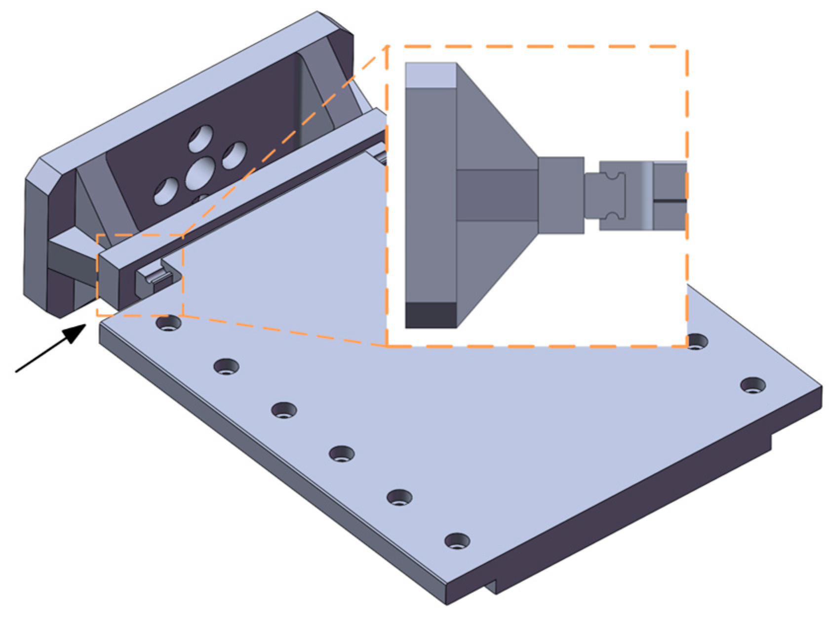
A key feature in this design lies in the functional integration of the connecting arms. Unlike traditional simple linkage rods, the connecting arms are engineered as multifunctional structural components made of 6061 aluminum alloy. As detailed in the magnified local feature diagram in Figure 3, the connecting arm serves not merely as a transmission rod but also as a carrier for the decoupling guide system. Specifically, the supporting rail of the cross-roller guide is integrated as part of the connecting arm itself, while the corresponding moving rail is embedded directly into the side of the Upper Moving Worktable. This distinct configuration creates a rigid, closed-loop transmission chain that contributes to high stiffness and compact assembly. Furthermore, compared to motor-mover-decoupled platforms, this integration strategy avoids the need for complex motor redesigns and contributes to a reduction in the overall platform volume.
Figure 3.
Local feature diagram of the connecting arm.
Detailed specifications regarding the platform’s geometric dimensions, kinematic limits of the guide rails (stroke and load capacities), and maintenance strategies addressing lubrication and wear are provided in Appendix A.
2.3. Decoupling Principle and Comparative Analysis
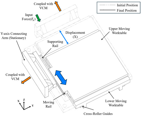
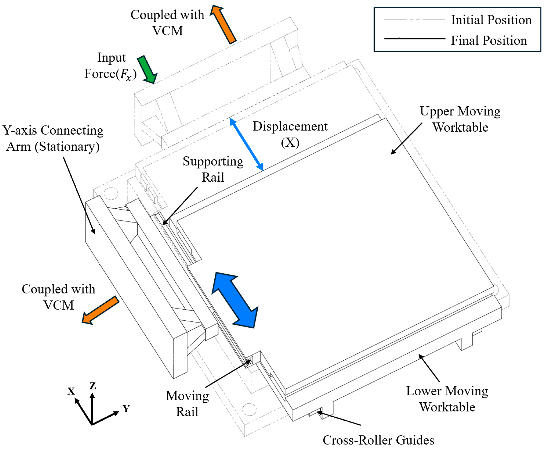
The platform’s decoupling is primarily achieved through its integrated connecting arm and guide rail design, which effectively mitigates the coupling interference between the X and Y axes. As depicted in the schematic diagram Figure 4, the decoupling is realized through a specific guide arrangement located at the interface between the connecting arm and the Upper Moving Worktable. When the X-axis VCM actuates, it drives the Lower Moving Worktable and the Upper Moving Worktable together in the X-direction. During this process, the moving rail embedded in the Upper Moving Worktable slides freely along the supporting rail of the stationary Y-axis connecting arm. This geometric constraint allows the motion stage to traverse the X-axis without dragging the Y-axis motor mover or its connecting arm. Consequently, the mass and inertia of the Y-axis drive unit are physically decoupled from the X-axis motion. Conversely, when the Y-axis VCM actuates, the force is transmitted through the connecting arm to push the Upper Moving Worktable along the Y-direction, guided by the cross-roller guides between the Upper and Lower tables. This orthogonal guide arrangement physically blocks the transmission path of parasitic forces, enabling the motion along one axis does not induce displacement or vibration in the other.
Figure 4.
Schematic diagram of the motion decoupling mechanism (X).
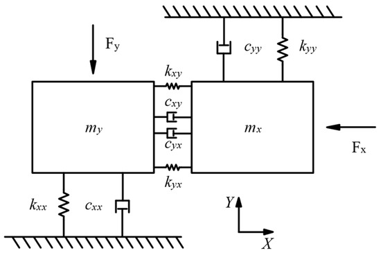
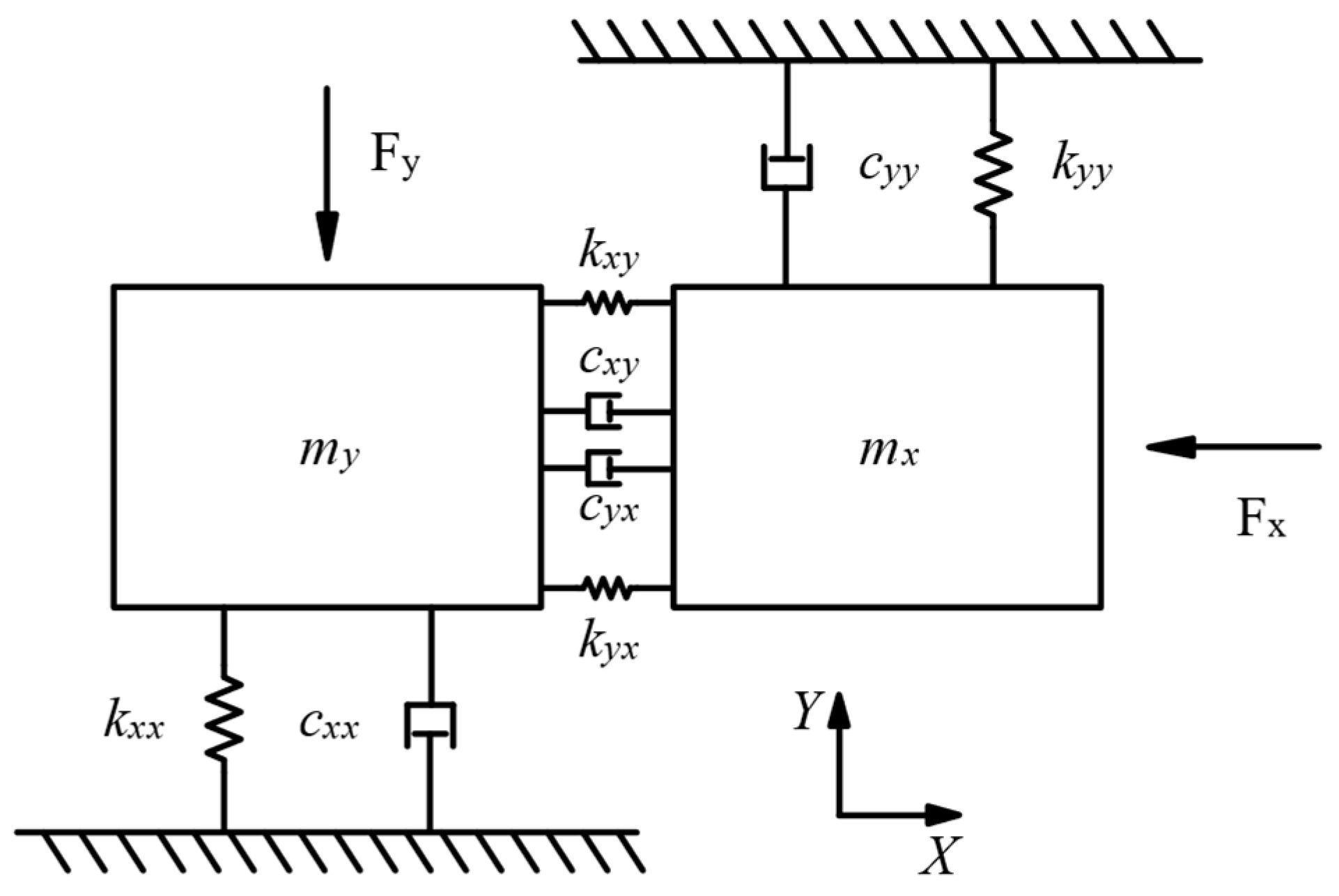
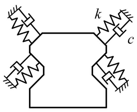
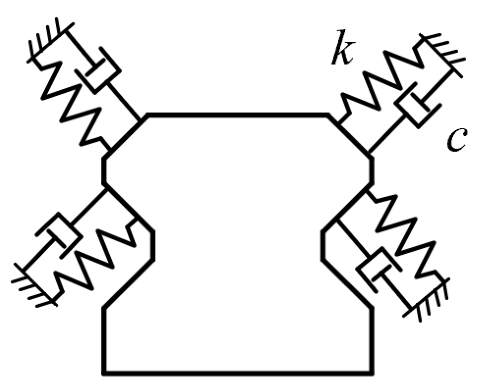
To analyze the dynamic behavior of the proposed platform, a 2-DOF lumped-parameter mechanical model is initially established, as illustrated in Figure 5. According to Newton’s second law, considering the transmission of structural deformation and friction, the dynamic equilibrium equations for the two moving masses in the XY plane can be expressed as:
Figure 5.
Schematic of the 2-DOF dynamic model.
Writing these equations in a compact matrix form yields a generic multi-input multi-output (MIMO) dynamic model of the platform:
In conventional stacked stages, the off-diagonal coupling terms are often significant due to parasitic forces between layers. To facilitate the theoretical decoupling of this MIMO system, the proposed Connecting Arm and Guide Rail Integration mechanism introduces specific physical and kinematic constraints to minimize these off-diagonal elements.
The simplification of the coupling stiffness matrix is facilitated by the structural design of the integrated cross-roller guides. This mechanical transmission path is intended to provide substantial structural rigidity and geometric constraints in the non-driving orthogonal directions, thereby restricting transverse parasitic deformation. Assuming this rigidity is sufficient, the transfer of elastic potential energy between the orthogonal axes is expected to be relatively small. Thus, it is considered reasonable to approximate the cross-coupling stiffness as zero compared to the principal stiffness ().
Similarly, the cross-axis damping terms can be reasonably neglected due to the low-friction characteristics of the driving mechanism. The relative motion between the X and Y axes relies primarily on the precision cross-roller guides. Because their rolling friction coefficient is generally much smaller than that of sliding friction, the tangential viscous drag and friction forces transmitted to the orthogonal axis are effectively minimized ().
Based on these physical boundary conditions, the generic coupled MIMO system can be mathematically simplified. By truncating the off-diagonal elements, the system can be treated as two independent 1-DOF Single-Input Single-Output (SISO) systems. Taking the X-axis as an example:
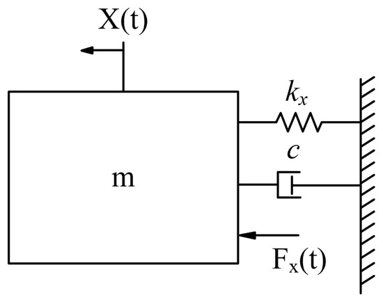
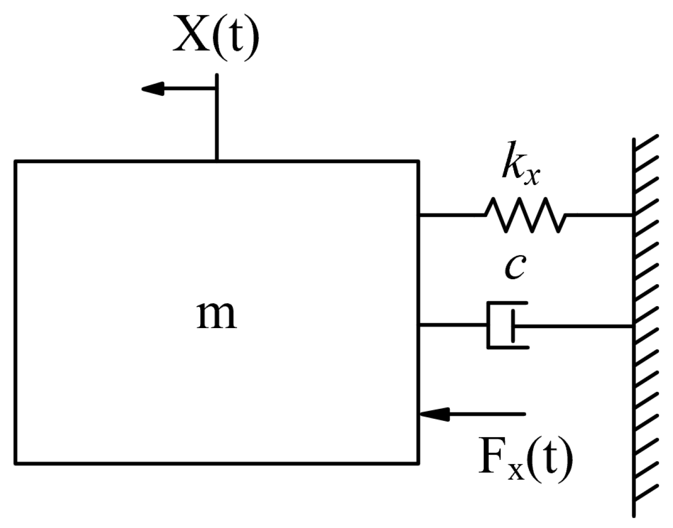
The X-direction sub-platform is modeled as a spring-damper-mass system, as shown in Figure 6, leading to the following equations:
Figure 6.
Spring-damper-mass model of the platform in X-direction.
Equation (6) is the Laplace transformation of Equation (5). The transfer function is
In Equation (7), represents the combined principal stiffness in the X-direction, which mainly consists of the VCM’s electromagnetic stiffness and the equivalent parasitic rolling stiffness provided by the orthogonal guide rail mechanisms. is the equivalent damping coefficient in the X-direction. Rewriting the transfer function in standard second-order form:
where and . It follows that a larger combined stiffness and a smaller mass of the X-direction moving worktable and its attachments lead to a higher natural frequency for the X-direction subsystem. Based on the nominal stiffness of the used Type R 3 guides and the moving mass, the theoretical natural frequency is calculated to be 898 Hz.
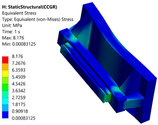
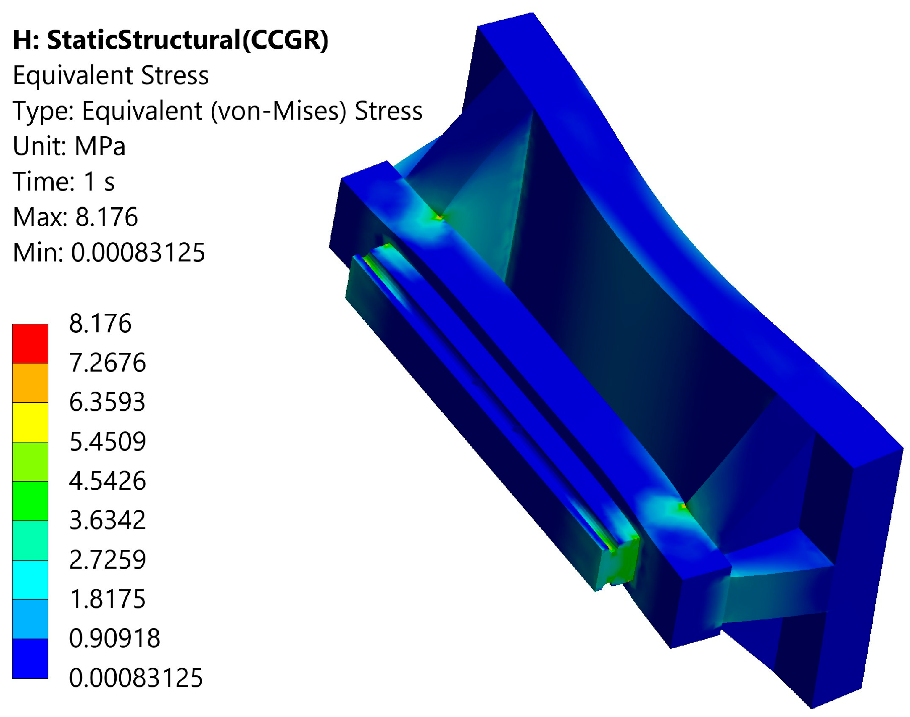
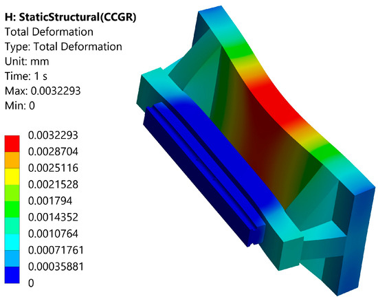
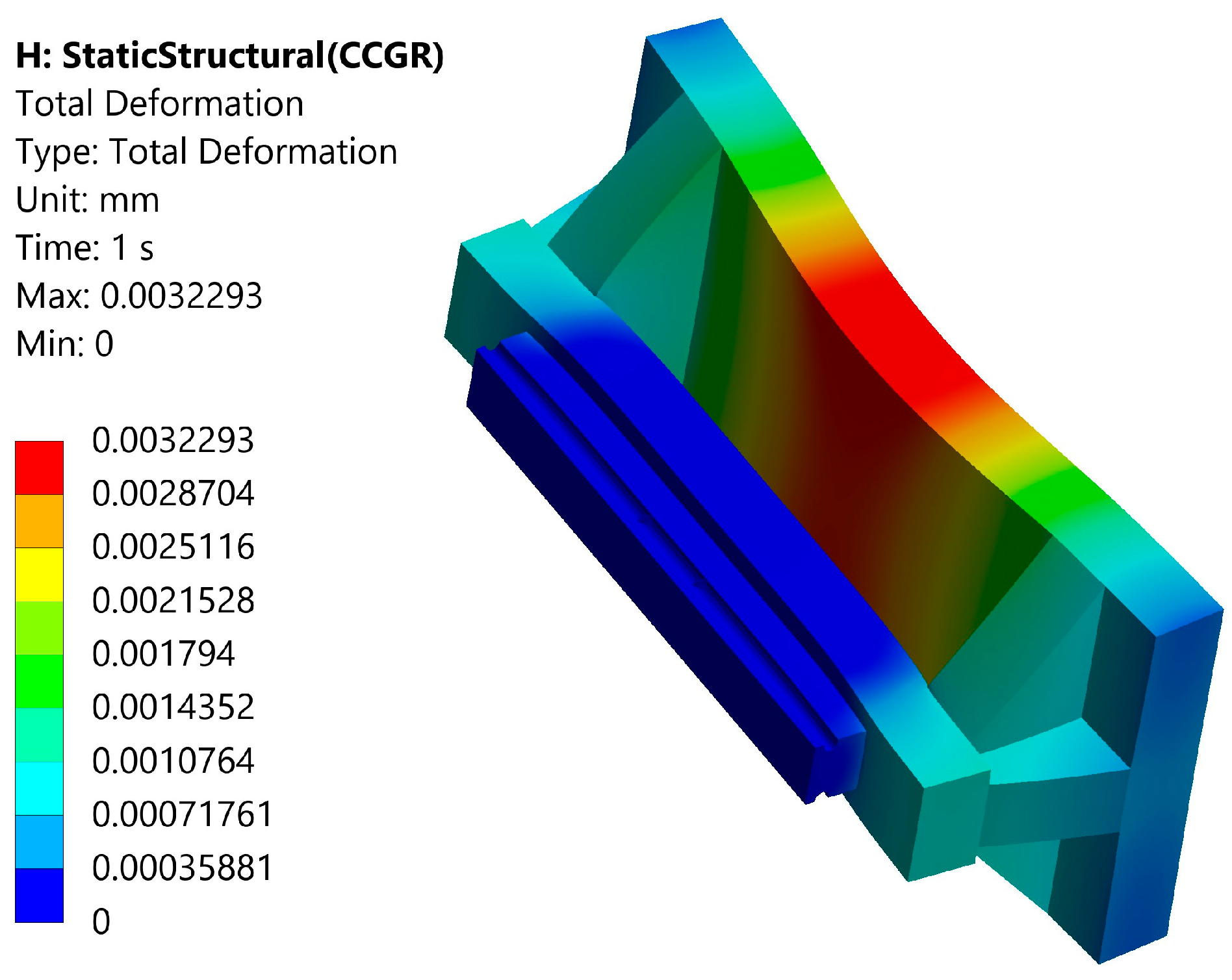
The theoretical decoupling assumption established above is predicated on the premise that the connecting arm possesses sufficient structural rigidity to resist dynamic driving forces without significant parasitic elastic deformation. To verify this, a finite element analysis was performed. A force of 331 N (the VCM’s maximum thrust) was applied. The connecting arm is made of 6061 aluminum alloy, meshed with tetrahedral elements. Results in Figure 7 show that the maximum stress is lower than the material’s yield strength, indicating a substantial safety margin. Figure 8 shows maximum deformation controlled at the nanometer level. These results confirm that the connecting arm enables precise power transmission with minimal elastic deformation, effectively avoiding the resonance frequency band and laying the foundation for high-bandwidth control.
Figure 7.
Equivalent stress results of the connecting arm.
Figure 8.
Total deformation results of the connecting arm.
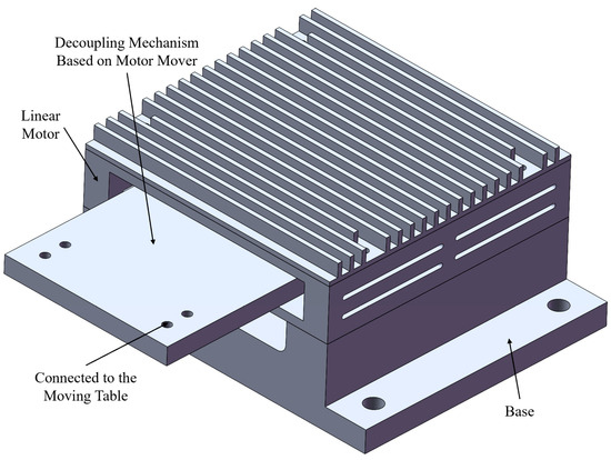
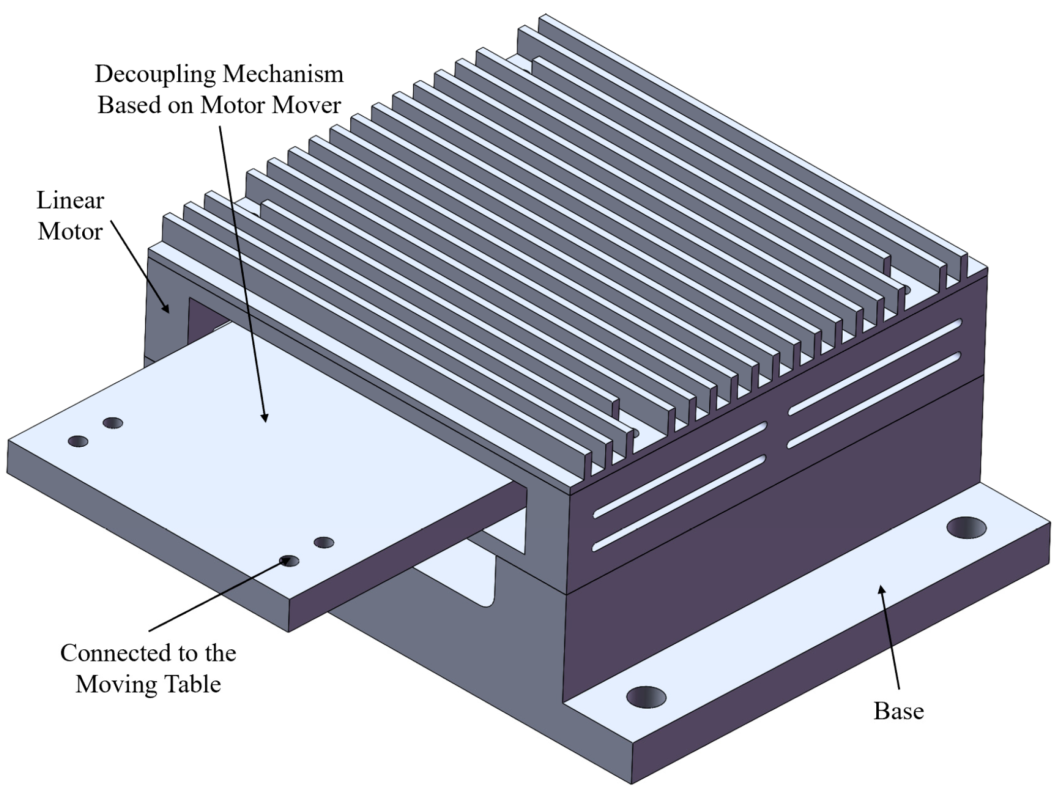
Building upon the structural analysis, a comparative discussion with the traditional “Motor Mover Decoupling” strategy is presented to illustrate the design rationale. In conventional designs, decoupling is often achieved by modifying the motor mover to accommodate planar motion, which typically involves a suspended mover structure as shown in Figure 9. Such configurations may present challenges regarding the local stiffness of the kinematic chain and can increase the complexity of motor manufacturing. Alternatively, the proposed decoupling structure aims to maintain a rigid connection by transferring the decoupling function to the external connecting arm-rail interface. As quantitatively summarized in Table 2, this approach yields a higher first-order natural frequency, indicating that the integrated arm-rail mechanism offers favorable structural stiffness and dynamic stability characteristics compared to the compliant mover approach.
Figure 9.
Schematic diagram of the platform based on motor mover decoupling.
Table 2.
Comparison of Two Decoupling Mechanisms.
3. Finite Element Analysis of the Platform
3.1. Static Analysis
Static analysis was conducted in Ansys Workbench. The simulation method for contact pairs between cross-roller guides and linear slides significantly impacts results [26]. This study uses spring-damper elements to simulate guide contact pair characteristics. Figure 10 shows the model for the bottom linear slide. Specifically, while the contact between the rollers and raceways is modeled using equivalent spring-damper elements to reflect the full interfacial characteristics, the damping components are assigned zero or negligible values in the static FEA session to focus on the stiffness-induced deformation results. For simulation convenience, the spring elements were placed using the remote point method. The simulation for cross-roller guides connecting the moving worktables follows the same method. The number of spring elements is determined by the number of rollers and guide length. Specifically, the imprint face function in Design Modeler was used to partition guide contact surfaces evenly, and spring elements were applied on corresponding partitions.
Figure 10.
Simulation of the bottom linear slide.
The main platform material is 6061 aluminum alloy, and the cross-roller guide material is GCr15. Relevant properties are listed in Table 3. Based on these material characteristics, the Von Mises equivalent stress is adopted as the failure criterion. This method utilizes the Distortion Energy Theory applicable to the ductile 6061 aluminum alloy and verifies that the high-strength GCr15 rails operate strictly within the linear elastic region.
Table 3.
Material Properties.
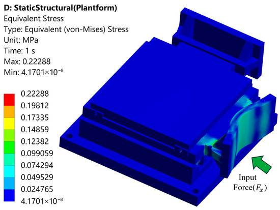
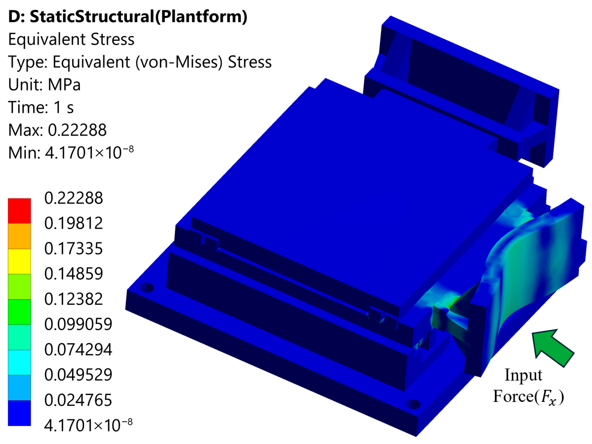
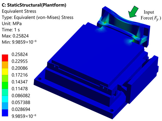
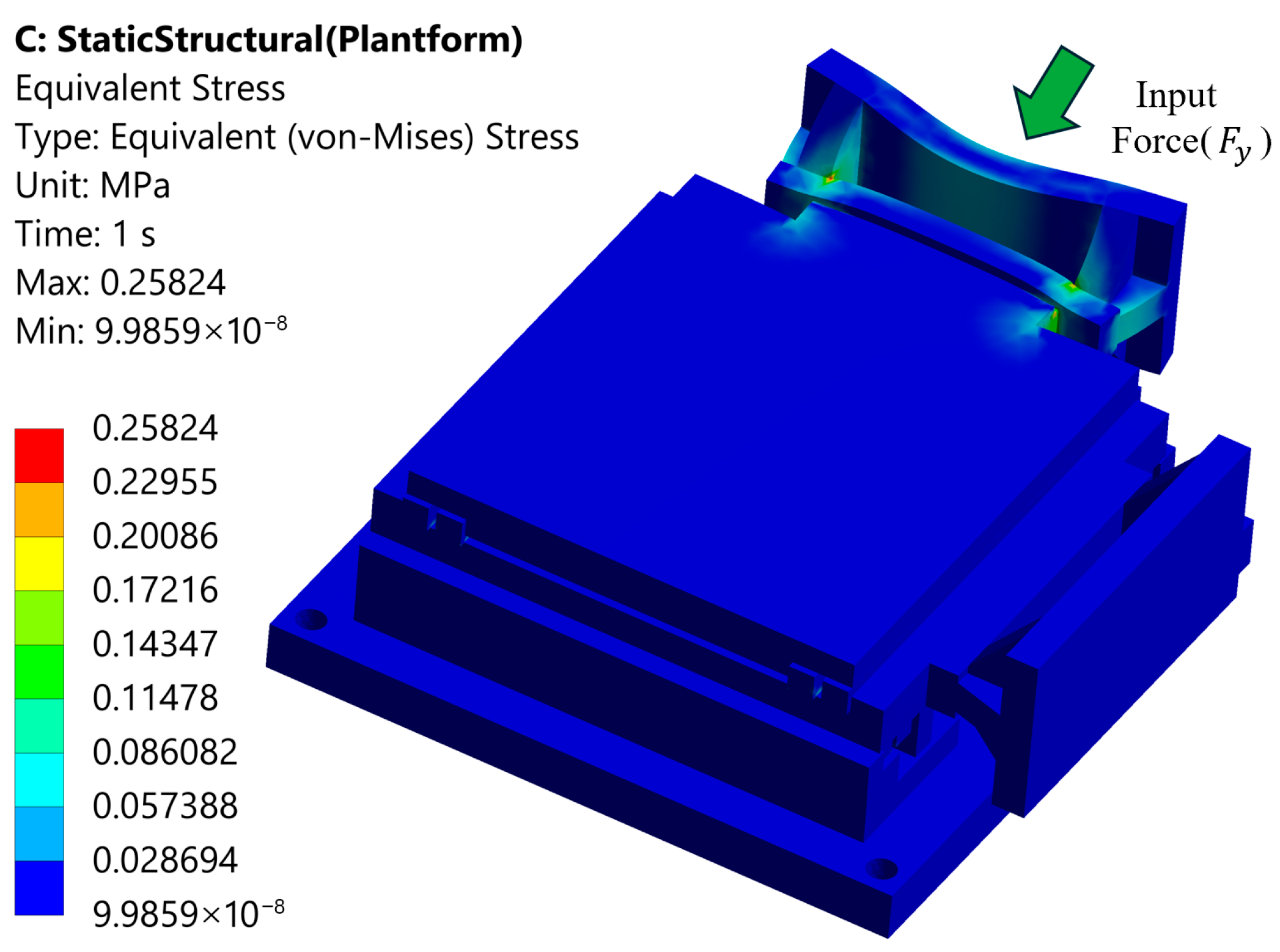
In the simulation, the platform moves at 100 mm/s with an acceleration of 10,000 mm/s2. A 1.18 kg object is mounted on the upper moving worktable. Per Newton’s second law, the required thrust forces are and . Applying these forces separately, static analysis results for the axes are shown in Figure 11 and Figure 12. Maximum equivalent stresses are 0.22 MPa (X-axis) and 0.26 MPa (Y-axis), with corresponding safety factors of 1091 and 923, exceeding conventional requirements, indicating sufficient structural safety.
Figure 11.
X-axis static analysis results of the platform.
Figure 12.
Y-axis static analysis results of the platform.
3.2. Modal Analysis
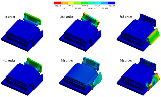
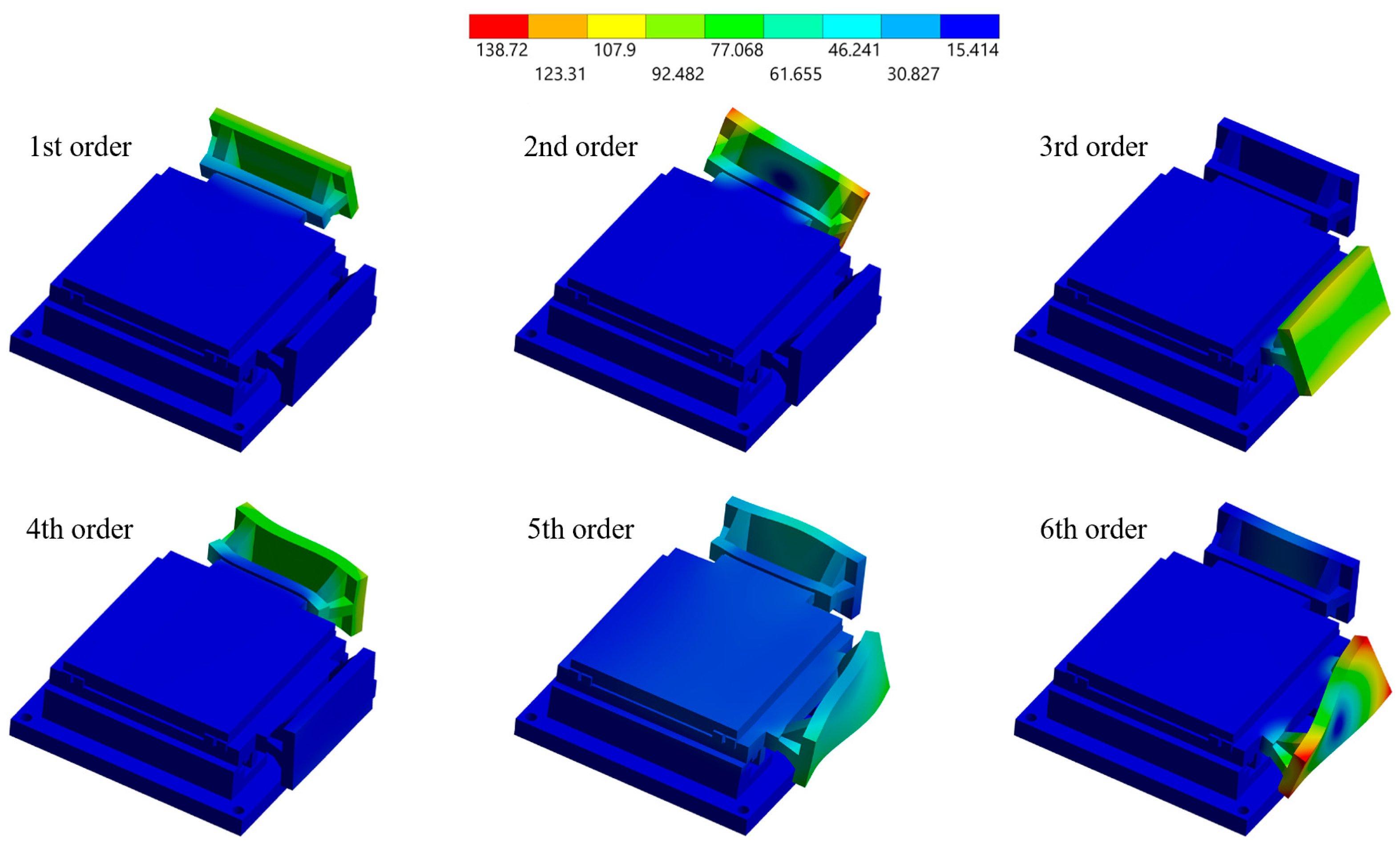
Modal analysis was performed using the Block Lanczos method. The first six extracted mode shapes are shown in Figure 13, with frequencies listed in Table 4. The first four modes are caused by the connecting arm in specific motor directions: the 1st and 3rd modes involve vertical bending, while the 2nd and 4th exhibit torsion. From the 5th mode, deformation becomes a complex combination of torsion and bending. Comparing these frequencies (864.82 Hz to 3532 Hz) with the VCM’s actuation frequency (89.35 Hz) confirms they are far greater, meeting the design objective.
Figure 13.
First six orders of natural frequencies of the platform.
Table 4.
Platform Natural Frequencies.
Furthermore, the first-order natural frequency obtained from FEA (864.82 Hz) aligns closely with the theoretical prediction (898 Hz) derived from the 1D simplified model in Section 2.2. This consistency not only verifies the accuracy of the simulation but also confirms the validity of the decoupling assumption.
Compared to the motor-mover decoupling method, the platform using the connecting arm decoupling shows significantly increased frequencies for the first two modes. It meets design requirements with smaller volume and mass, without complex mechanisms like motor redesign, offering greater modularity and improved dynamic performance.
3.3. Parametric Optimization of the Connecting Arm
As revealed in the modal analysis (Section 3.2), the first four modes of the platform are primarily governed by the connecting arm. In the absence of a basic analytical model for this complex integrated structure, Response Surface Optimization (RSO) is conducted to explore different sets of geometric parameters. This parametric study provides the necessary design information to further optimize the platform’s static and dynamic performance.
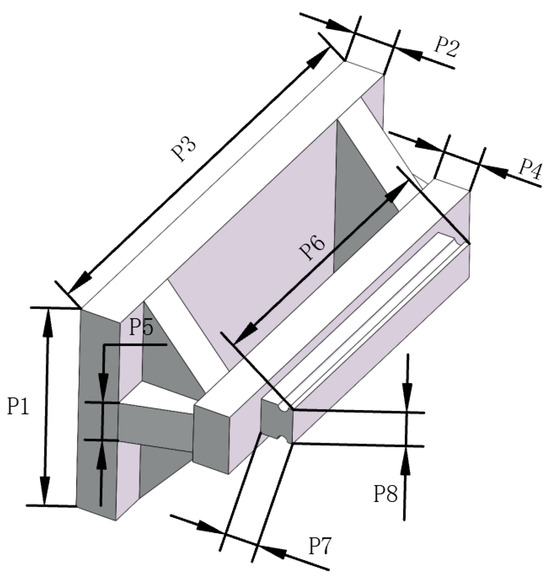
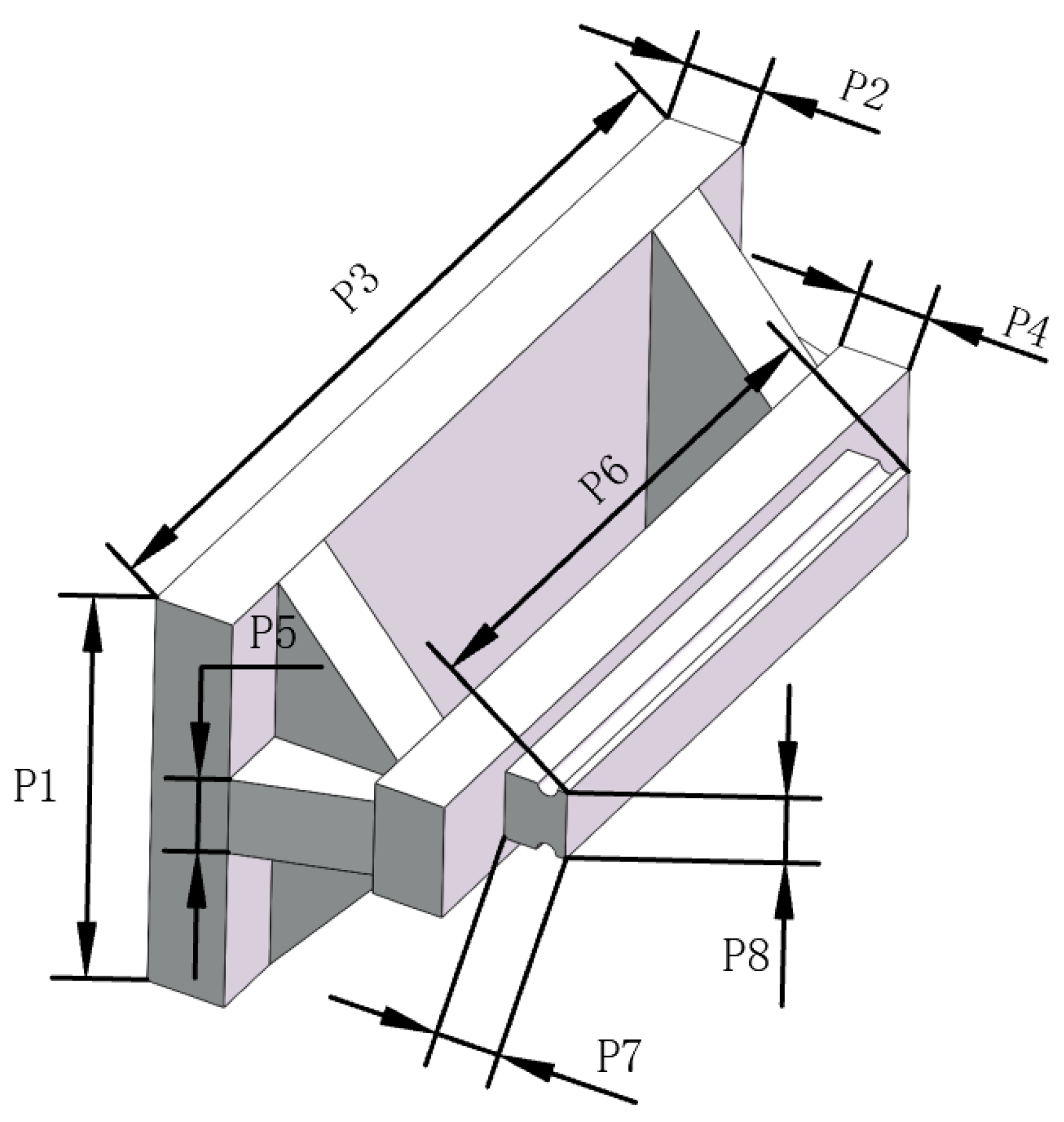
Eight key geometric dimensions of the connecting arm (denoted as P1 to P8, representing specific thicknesses and widths, see Figure 14) were selected as input variables. The evaluation criteria (responses) included the component mass (P9), maximum static deformation (P10), maximum equivalent elastic strain (P11), maximum equivalent stress (P12), and the 1st natural frequency (P13). The Design of Experiments (DOE) was formulated utilizing Latin Hypercube Sampling (LHS) to generate Central Composite Design (CCD) samples. Initially, 81 design points were generated. After manually excluding 4 design points due to geometric rebuilding failures during the parametric update process, the remaining 77 valid design points were successfully solved. Subsequently, to achieve an accurate mapping between variables and responses, the Genetic Aggregation algorithm was employed to construct the surrogate model. Cross-validation of this Genetic Aggregation model demonstrated high accuracy, with the coefficient of determination (R2) exceeding 0.99 for mass, deformation, and frequency, indicating the high reliability of the predicted structural behaviors.
Figure 14.
Selection of geometric dimensions.
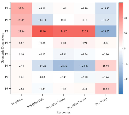
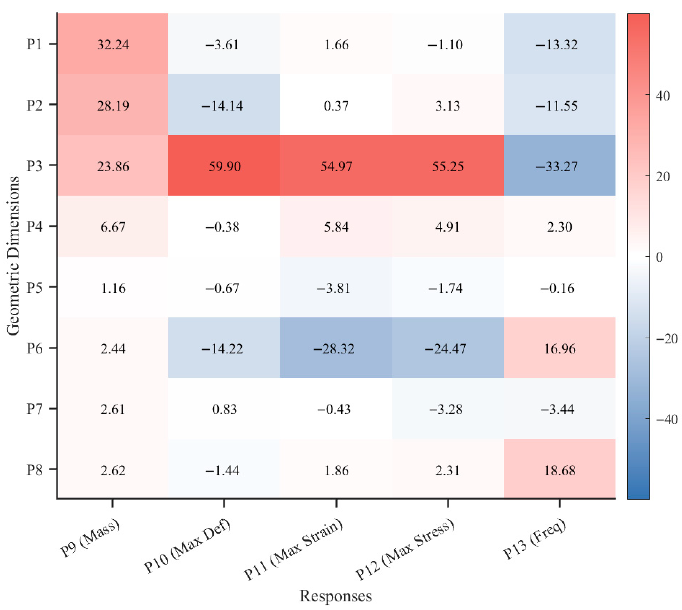
To derive design conclusions, a local sensitivity analysis was extracted from the surrogate model (Figure 15). The analysis indicates that parameter P3 primarily influences both static rigidity and dynamic response. An increase in P3 significantly exacerbates total deformation (sensitivity 59.9%) and reduces the fundamental frequency (sensitivity −33.2%). Conversely, moderately expanding parameters P6 and P8 favorably enhance dynamic stiffness. These derived conclusions map the geometric influence on the desired design performance, replacing the need for a traditional analytical model.
Figure 15.
Local sensitivity heatmap.
Based on sensitivity insights, multi-objective optimization was established. The optimization criteria were prioritized to minimize the mass (P9) and maximum static deformation (P10), while maximizing the 1st natural frequency (P13). Driven by the Multi-Objective Genetic Algorithm (MOGA), a global Pareto-optimal front was explored. Table 5 compares the initial design of the connecting arm (which was evaluated in Section 3.1 and Section 3.2) with the optimal candidate generated by the MOGA.
Table 5.
Performance comparison between the initial and optimized designs of the connecting arm.
As shown in Table 5, the optimized connecting arm exhibits a 51.3% increase in its 1st natural frequency (reaching 1522.66 Hz) and a 41.4% reduction in maximum deformation, alongside a 14.1% mass reduction.
While the initial design evaluated in Section 3.1 and Section 3.2 satisfies the current operational requirements and proves the feasibility of the decoupling mechanism (as will be experimentally verified in Section 3.4 and Section 4), this parametric analysis systematically validates the significant potential of the proposed structure. The derived optimal geometric sets establish design guidelines and information for future ultra-high-frequency and high-precision applications.
3.4. Dynamic Performance Analysis
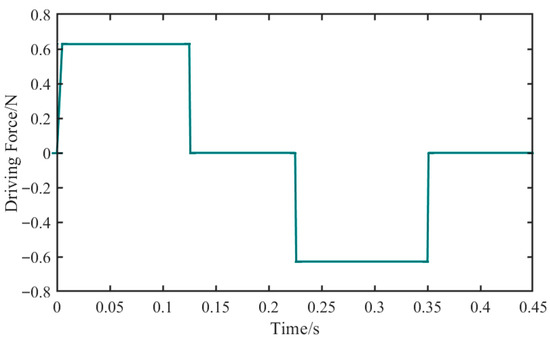
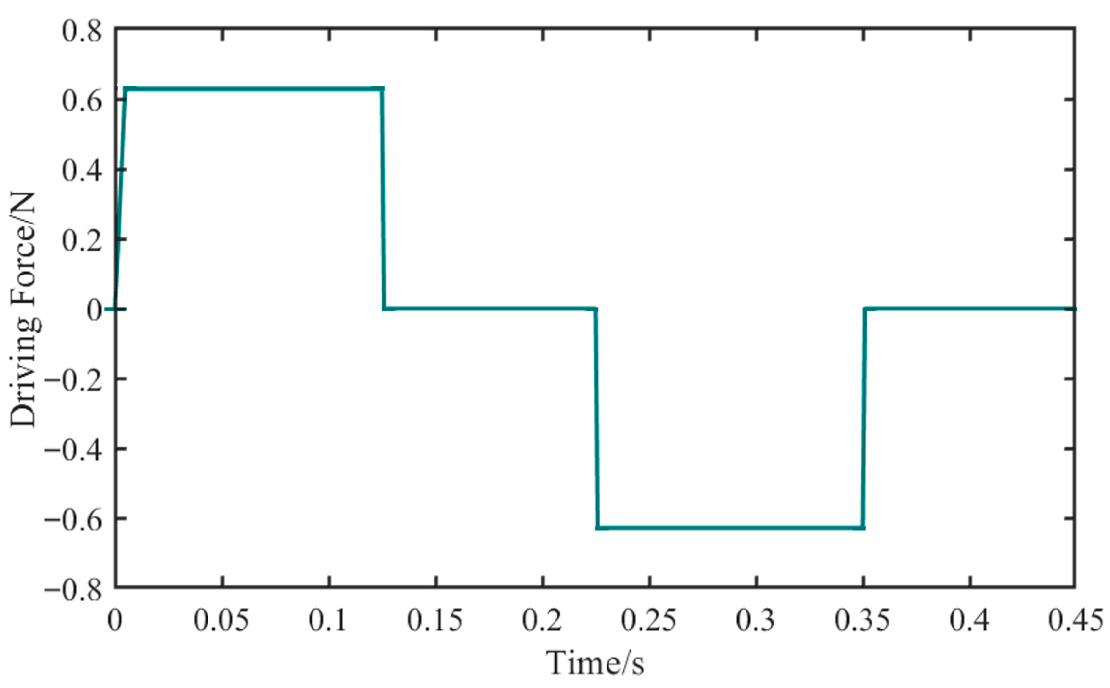
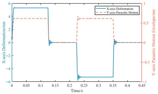
To accurately evaluate the dynamic behavior of the positioning platform during actual motion and address the limitations of relying solely on static calculations, a transient structural analysis was conducted. The finite element model inherits the mesh settings and boundary conditions from the static analysis, where the cross-roller guides are consistently modeled using equivalent spring-damper elements. The specific profile of the applied time-varying force is illustrated on Figure 16.
Figure 16.
Time-varying driving force profile based on the experimental trapezoidal velocity planning.
Regarding the load application, to replicate the trapezoidal velocity profile used in the experimental tests (target velocity of 50 mm/s and acceleration of 400 mm/s2), the motion process was translated into a time-varying force profile applied to the center of the voice coil motor mover. Based on Newton’s second law and the equivalent moving mass of the platform in the X-axis (approximately 1.57 kg), the theoretical driving force required during the rapid acceleration and deceleration phases is calculated to be 0.628 N. Consequently, the entire 0.45 s transient simulation cycle was divided into four loading stages that correspond to the physical motion phases.
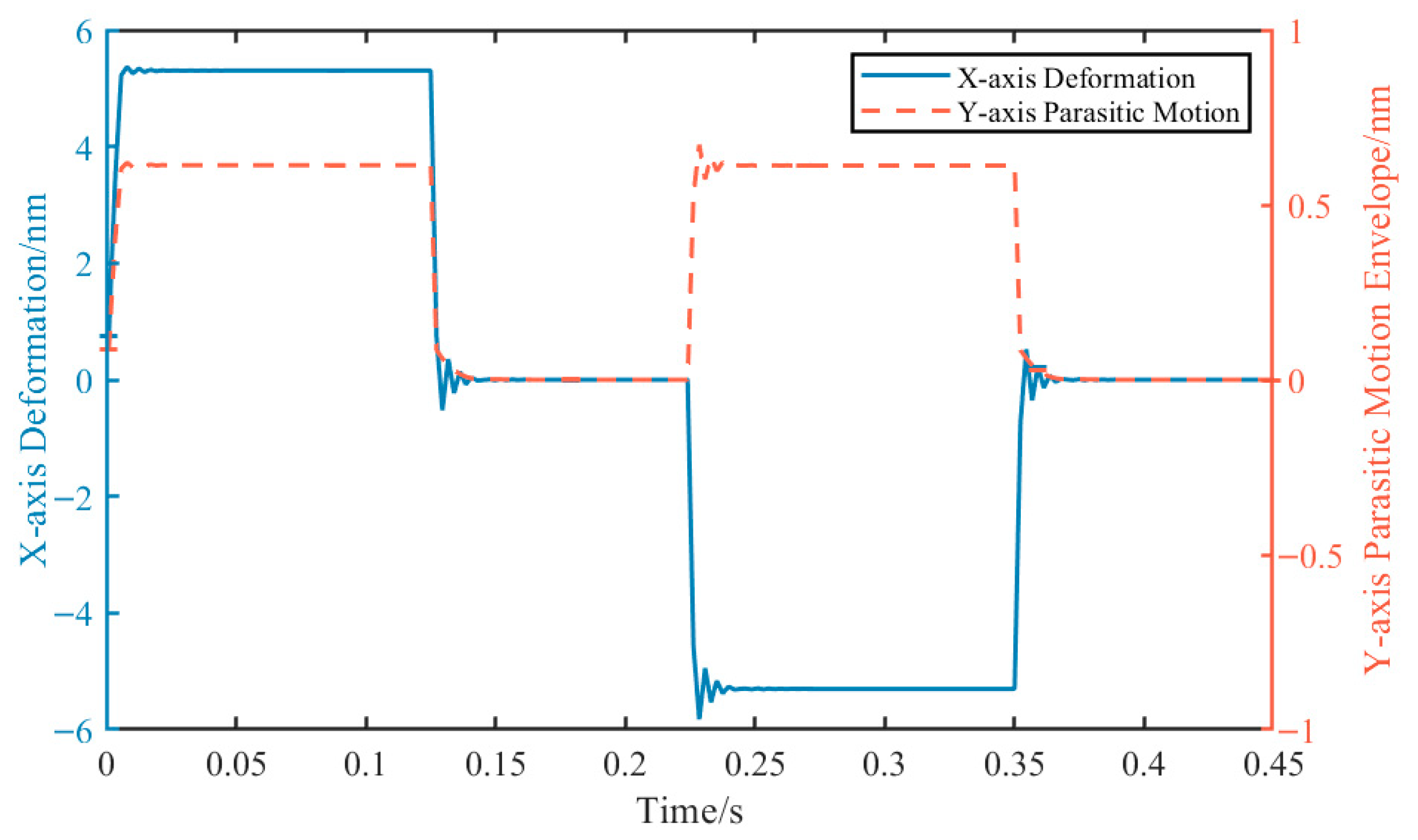
Simulation results indicate that in the driving direction (X-axis), the maximum dynamic deformation of the structure is about 5.3 × 10⁻⁶ mm (i.e., 5.3 nm) during the rapid acceleration and deceleration phases. Furthermore, when the driving force is removed and the platform enters the constant velocity or stationary state, the deformation in the X-axis decreased to a low level (in the order of 10−10 mm), with no significant low-frequency residual vibration observed. This indicates that the platform not only possesses high dynamic stiffness but also effectively dissipates system energy, contributing to the stability of the high-frequency dynamic response.
More importantly, during the entire cycle of rapid X-axis motion, the maximum parasitic displacement generated in the orthogonal Y-axis direction is about 6.1 × 10⁻⁷ mm (i.e., 0.61 nm). This sub-nanometer cross-axis coupling value indicates minimal cross-axis coupling. The comparative transient displacement responses between the main driving direction (X-axis) and the orthogonal direction (Y-axis) are illustrated in Figure 17. These detailed transient dynamic simulation results demonstrate that the proposed decoupling mechanism integrating the connecting arm and guide rails effectively isolates the transmission path of parasitic motion. This allows the system to maintain favorable motion decoupling performance and high dynamic positioning accuracy even under the impact of high dynamic loads.
Figure 17.
Dynamic displacement response of the moving worktable.
4. Experimental Measurement and Results
4.1. Experimental Platform Setup
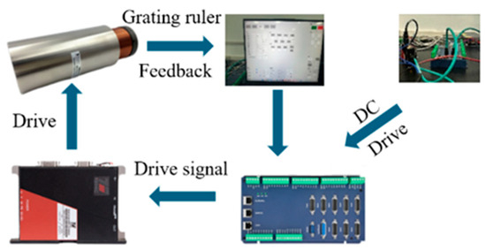
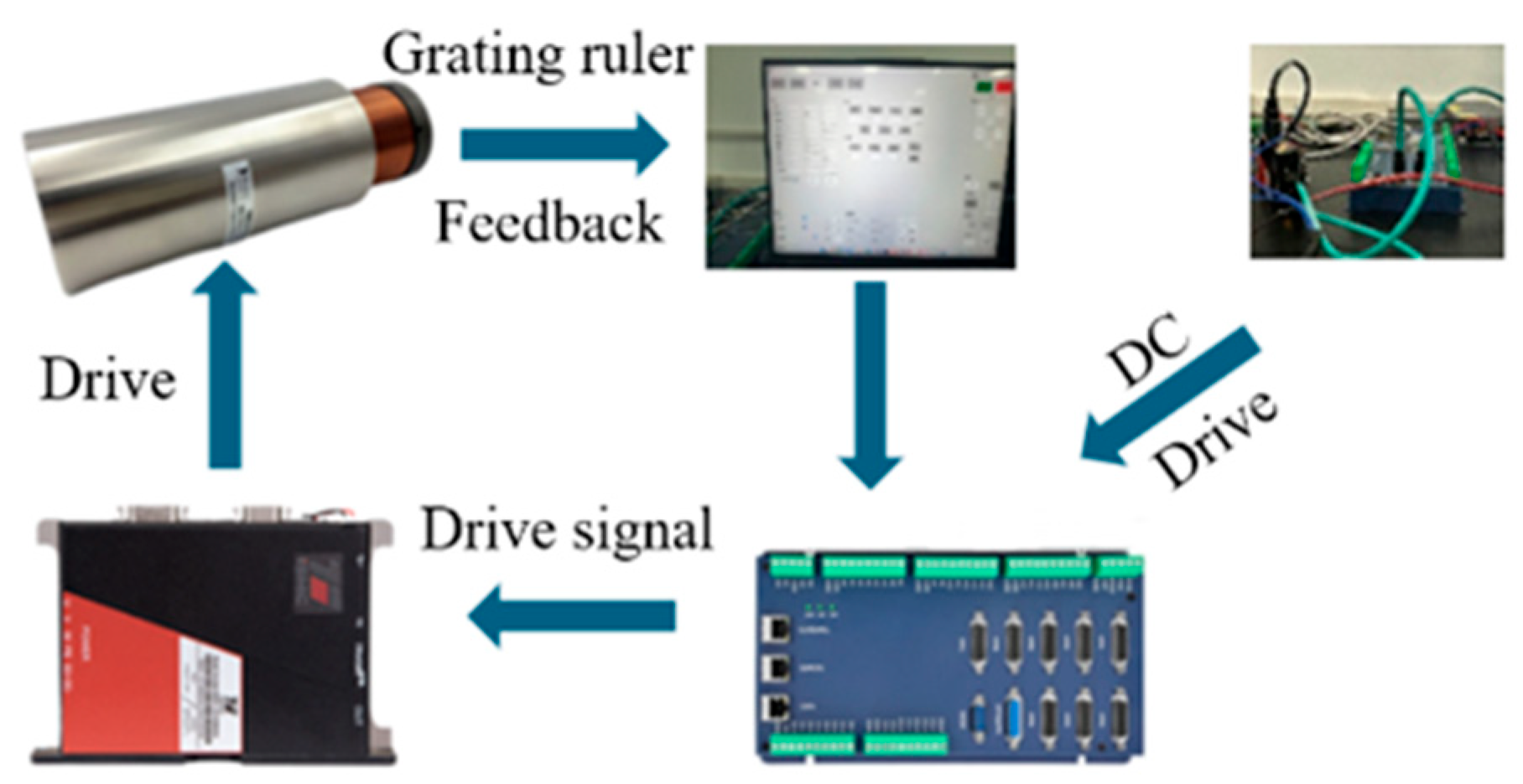
Figure 18 shows the experimental platform framework. The material is 6061 aluminum alloy. The platform consists of cross-roller guides (SCHNEEBERGER R series, Roggwil, Switzerland), a controller (Zmotion ZMC308E, Shenzhen, China), and drivers (iSMC Sapphire series, Shanghai, China). A linear encoder (Lamotion RX series, 5 μm resolution, Dalian, China) collects data for analyzing responsiveness, stiffness, natural frequency, etc. The platform is DC-powered. Drivers amplify controller signals to drive the VCMs. The linear encoder provides real-time position feedback for closed-loop control.
Figure 18.
Experimental platform setup framework.
4.2. Experimental Measurement
Experiments were conducted under three conditions: speeds of 50 mm/s and 100 mm/s with acceleration/deceleration of 200 mm/s2, and speed of 50 mm/s with acceleration/deceleration of 400 mm/s2. Steady-state error data was collected.
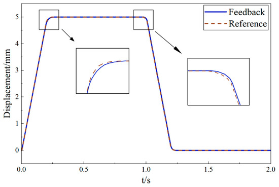
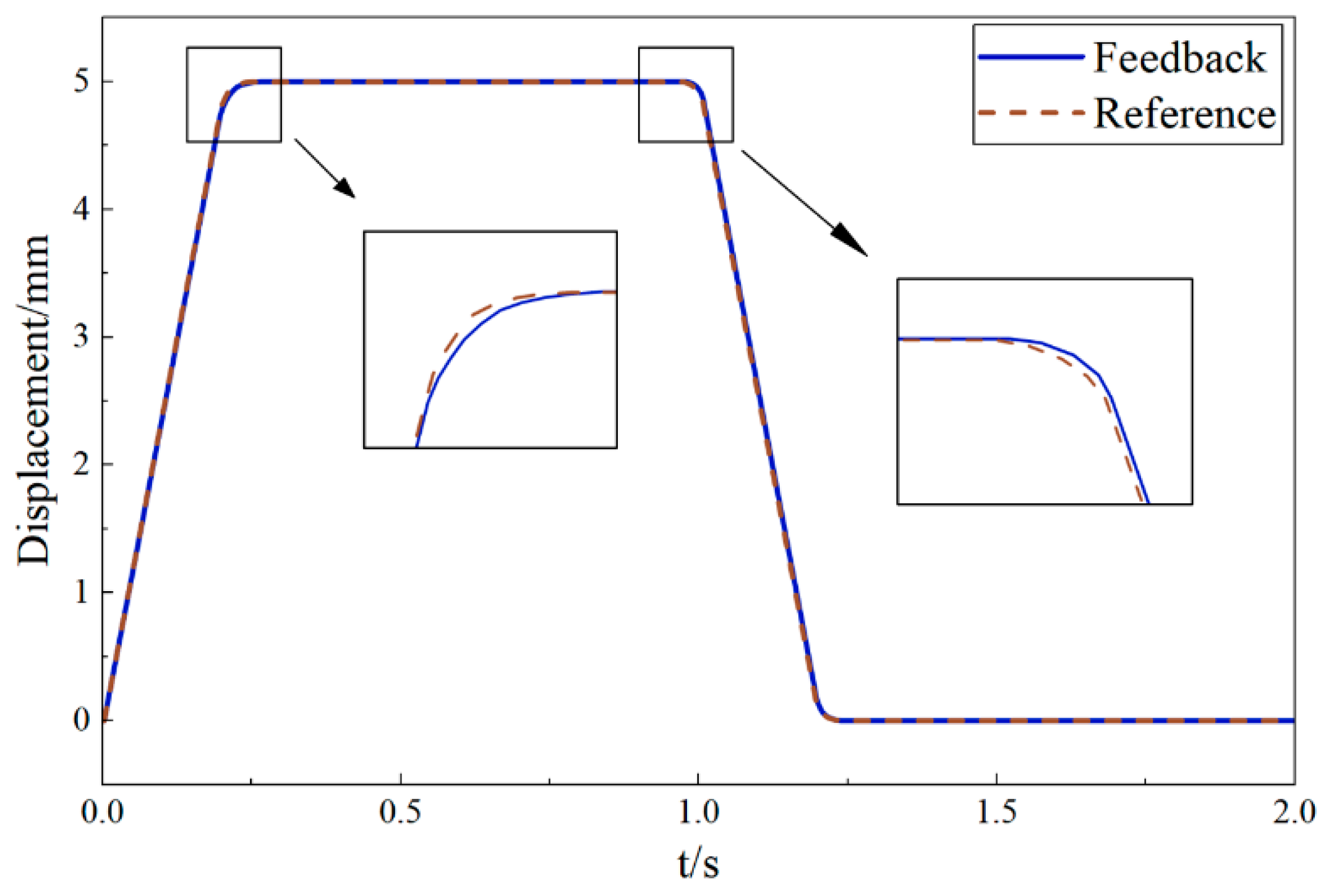
Based on this data, the displacement signal tracking lag performance was analyzed. A 5 mm amplitude, 1 Hz sinusoidal current signal was input, and output displacement was measured. Tracking results (Figure 19) show good response-following characteristics under closed-loop control.
Figure 19.
Displacement signal lag performance of the positioning platform.
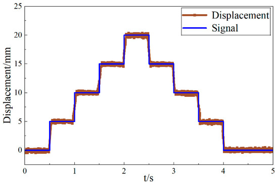
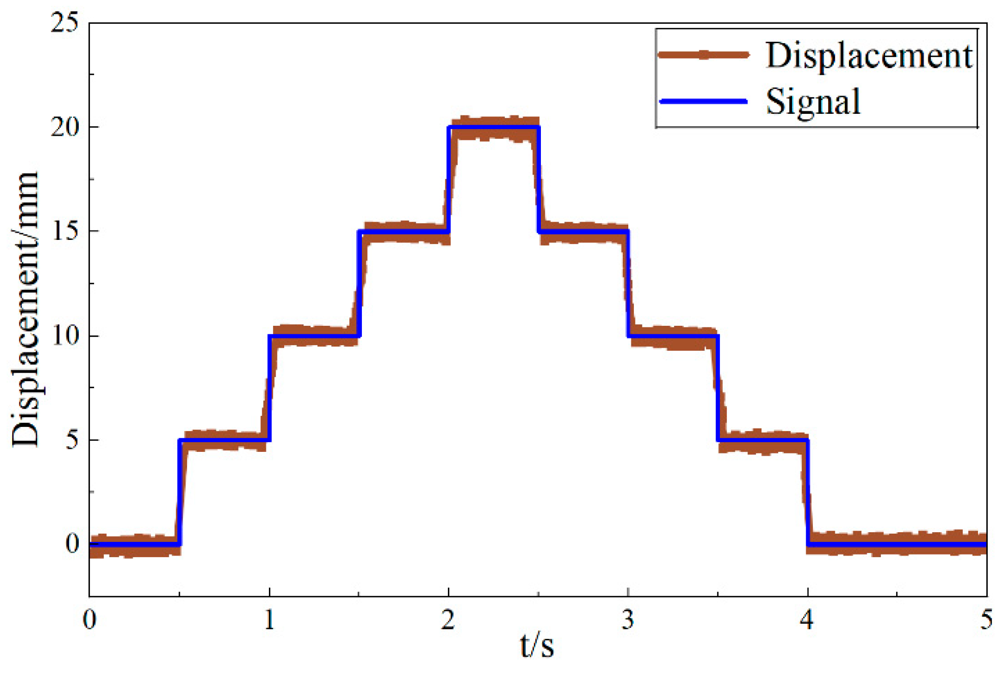
Closed-loop positioning accuracy was tested using a step signal: 5 mm step length, 4 steps, 0.5 s per step. The reference and actual displacement response are shown in Figure 20. To systematically assess the measurement repeatability and uncertainty of the platform, the steady-state holding phases across these multiple steps were analyzed. Statistical analysis of the error between measured and reference displacement yielded a standard deviation σ across different step cycles, demonstrating favorable measurement repeatability. In terms of overall measurement uncertainty, the primary contributing factors in this setup are the resolution of the Lamotion linear encoder and unmodeled environmental vibrations. Using 1.65σ as a 90% confidence interval metric, the platform reliably achieved a single-step displacement of 4.995 mm. Thus, the positioning deviation for a 5 mm step command is evaluated to be within an uncertainty band of 0.005 mm, verifying the positioning reliability and the feasibility of the decoupling mechanism under actual operating conditions.
Figure 20.
Precise resolution of the positioning platform.
5. Conclusions
To address bottlenecks in existing XY precision positioning platforms, such as motion coupling, large parasitic errors, low natural frequency, and dynamic instability, this study proposes and implements a precision platform based on a decoupling mechanism that integrates a connecting arm with guide rails. Through theoretical modeling, finite element simulation, and experimental validation, the main conclusions are as follows:
- Proposed Decoupling Mechanism and Comparative Advantages: The designed structure integrates the motion decoupling function directly into the rigid connecting arm. Unlike traditional flexure-based mechanisms limited by micrometer-level strokes or mover-decoupling platforms that may compromise stiffness due to slender designs, this solution achieves a millimeter-level macro-stroke while maintaining a compact and high-stiffness assembly.
- Dynamic Performance and Resonance Mitigation: Quantitative results suggest that the first-order natural frequency of the proposed connecting arm reaches 1014 Hz, which is nearly double the 564.97 Hz reported for traditional motor-mover decoupling structures. The platform’s overall first-order frequency (864.82 Hz) is considerably higher than the VCM’s actuation frequency (89.35 Hz), which avoids low-frequency resonance and supports system stability under high-bandwidth control.
- Mechanical Reliability and Parasitic Motion Suppression: Static and transient analyses confirm that the structure possesses sufficient mechanical strength reserves. Furthermore, transient dynamic simulations indicate that the mechanism suppresses cross-axis parasitic displacement to a sub-nanometer level (0.61 nm) during high-acceleration maneuvers, providing initial evidence of the decoupling effectiveness of the integrated arm-rail design compared to certain rigid solutions.
- Experimental Validation and Positioning Reliability: To enhance the evaluation, a preliminary analysis of measurement repeatability and uncertainty was incorporated. For a 5 mm step command, the positioning deviation is evaluated within an uncertainty band of 0.005 mm based on a 1.65σ confidence interval. These results suggest that the proposed platform offers a feasible alternative for high-performance precision positioning in terms of rigidity and stability.
The newly designed positioning platform, by introducing a decoupling structure combining a connecting arm with guide rails, effectively achieves motion decoupling while suppressing parasitic motion, enhancing modularity and overall stiffness. Both experimental and simulation results indicate that the platform based on this decoupling method is competitive with existing structures in stiffness and stability, validating its feasibility for precision positioning applications.
Although this study has demonstrated the basic feasibility and structural advantages of the proposed decoupling mechanism, the current prototype represents only an initial exploration. Acknowledging that a comprehensive dynamic evaluation involving complex contours is essential for practical applications, our immediate future work will focus on the coordinated motion control of the system. Moving forward, we plan to physically manufacture an upgraded prototype utilizing the optimal geometric parameters derived from the Multi-Objective Genetic Algorithm (MOGA) to experimentally evaluate theoretical gains in natural frequency and lightweighting. Utilizing this optimized platform, we will conduct systematic coordinated motion experiments, such as circular trajectory tracking, to further validate the dynamic coupling errors in physical scenarios. Building upon this refined mechanical foundation—where sub-nanometer cross-axis coupling has been theoretically achieved—our subsequent efforts will explore advanced nonlinear control strategies, such as Active Disturbance Rejection Control (ADRC). These strategies are anticipated to better mitigate complex friction and external disturbances, thereby refining high-speed trajectory tracking accuracy. Furthermore, as prolonged high-acceleration operations inherently introduce thermal challenges from the voice coil motors, investigating thermal-structural coupling effects and developing real-time compensation models will be a vital direction to maintain the platform’s long-term positioning reliability in practical demanding environments.
Author Contributions
Conceptualization, J.J., Y.F. and X.F.; formal analysis, J.J., Y.F. and X.F.; investigation, J.Z. and H.C.; supervision, J.J. and Z.X.; writing—original draft, Y.F. and X.F.; writing—review and editing, J.J., Y.F. and X.F.; data curation, J.Z., H.C., Z.Z. and L.L.; funding acquisition, L.L., Z.Z. and Z.X. All authors have read and agreed to the published version of the manuscript.
Funding
This research was funded by National Natural Science Foundation of China (NSFC): 52405225, 52505644; Henan Provincial Science and Technology Tackling Project: 252102221029, 252102220101, 262102220033, 262102241041; Henan Provincial Key Research and Development Program: 231111231200; International Science and Technology Cooperation Cultivation Project of Henan Province: 262102520054; Natural Science Foundation of Henan: 262300420047.
Data Availability Statement
The original contributions presented in this study are included in the article. Further inquiries can be directed to the corresponding author.
Conflicts of Interest
The authors declare no conflicts of interest.
Appendix A
Appendix A.1
This section supplements the detailed physical parameters, kinematic limits, and maintenance strategies. The overall dimensions and kinematic limits of the platform are listed in Table A1. The platform employs SCHNEEBERGER Type R 3 precision cross-roller guides. To promote safety and precision, the effective working stroke is designed to be within the nominal mechanical stroke of the guide rails.
Table A1.
Geometric and Kinematic Parameters of the Platform.
Appendix A.2
The mechanical characteristics of the utilized SCHNEEBERGER Type R 3-150-21z cross-roller guides are detailed in Table A2. These parameters support the system’s robustness against high-frequency dynamic loads and environmental variations.
Table A2.
Mechanical Characteristics of the Guide Pairs.
Appendix A.3
To address potential issues related to friction and wear, the guide rails utilized in this study are composed of GCr15 bearing steel with a hardness of 58–62 HRC, which provides a reasonable degree of wear resistance under normal operating conditions. To further mitigate friction, appropriate lubricating grease is applied to the contact surfaces of the guides. This lubrication strategy is intended to lower the friction coefficient and minimize the risk of wear during reciprocating motion. Furthermore, a regular maintenance schedule involving periodic re-lubrication is suggested to support the long-term stability of the platform.
References
- Li, X.; Zhang, L.; Jiang, B.; Fang, J.; Zheng, Y. Research Trends in China for Macro-Micro Motion Platform for Microelectronics Manufacturing Industry. J. Adv. Mech. Des. Syst. Manuf. 2021, 15, JAMDSM0032. [Google Scholar] [CrossRef] [Scilit]
- Liu, M.; Yu, Y.; Cui, L.; Ji, N.; Deng, X. Research on Micro-/Nano-Positioning System Driven by a Stepper Motor. Actuators 2024, 13, 246. [Google Scholar] [CrossRef] [Scilit]
- Yuan, L.; Wang, L.; Qi, R.; Li, Y.; Liu, C.; Luo, G. A 2-DOF Piezoelectric Platform for Cross-Scale Semiconductor Inspection. Int. J. Mech. Sci. 2024, 284, 109765. [Google Scholar] [CrossRef] [Scilit]
- Zhang, Y.; Hu, G.X.; Gong, J.; Wei, X.T. Key Technologies and Development of Micro-Nano Positioning Platform with Large Travel. Appl. Mech. Mater. 2011, 55–57, 929–932. [Google Scholar] [CrossRef] [Scilit]
- Li, J.; Zhao, H.; Qu, X.; Qu, H.; Zhou, X.; Fan, Z.; Ma, Z.; Fu, H. Development of a Compact 2-DOF Precision Piezoelectric Positioning Platform Based on Inchworm Principle. Sens. Actuators A Phys. 2015, 222, 87–95. [Google Scholar] [CrossRef] [Scilit]
- Yuan, L.; Wang, L.; Qi, R.; Zhao, Z.; Jin, J.; Zhao, C. A Novel Hollow-Type XY Piezoelectric Positioning Platform. Int. J. Mech. Sci. 2023, 255, 108496. [Google Scholar] [CrossRef] [Scilit]
- Gan, J.; Xie, W.; Yang, W.; Lei, S.; Lei, B. Design of a Novel Z-Shaped Flexure Hinge and a 2DOF XY Precision Positioning Platform. Precis. Eng. 2025, 93, 459–469. [Google Scholar] [CrossRef] [Scilit]
- Dong, G.; Sun, S.; Kong, X.; Chen, X.; Yin, T.; Wu, N.; Huang, P.; Wang, Z. Design and Analysis of a New Micro-Positioning Platform for Ceramic Material Testing. Microsyst. Technol. 2024, 30, 55–64. [Google Scholar] [CrossRef] [Scilit]
- Li, C.; Kang, S. Preliminary Design and Simulation Analysis of a Novel Large-Stroke 3-DOF Parallel Micro-Positioning Platform. Machines 2025, 13, 404. [Google Scholar] [CrossRef] [Scilit]
- Tian, Y.; Liu, C.; Liu, X.; Wang, F.; Li, X.; Qin, Y.; Zhang, D.; Shirinzadeh, B. Design, Modelling and Characterization of a 2-DOF Precision Positioning Platform. Trans. Inst. Meas. Control 2015, 37, 396–405. [Google Scholar] [CrossRef] [Scilit]
- Huang, H.; Zhao, H.; Fan, Z.; Zhang, H.; Ma, Z.; Yang, Z. Analysis and Experiments of a Novel and Compact 3-DOF Precision Positioning Platform. J. Mech. Sci. Technol. 2013, 27, 3347–3356. [Google Scholar] [CrossRef] [Scilit]
- Wang, G.; Wang, Y.; Lv, B.; Ma, R.; Liu, L. Research on a New Type of Rigid-Flexible Coupling 3-DOF Micro-Positioning Platform. Micromachines 2020, 11, 1015. [Google Scholar] [CrossRef] [Scilit] [PubMed]
- Sun, F.; Hao, Y.; Xu, F.; Jin, J.; Li, Q.; Tong, L.; Zhang, M.; Zhang, X. Proposal of an Equal-Stiffness and Equal-Stroke 2D Micro-Positioning Platform Driven by Piezoelectric Actuators. Actuators 2020, 9, 47. [Google Scholar] [CrossRef] [Scilit]
- Zhang, L.; Yan, H.; Sun, H.; Hu, M. Multi-Objective Optimization of Flexible Positioning Platform Considering Displacement Frequency and Dynamic Stiffness Responses. Sci. Rep. 2025, 15, 8904. [Google Scholar] [CrossRef] [Scilit] [PubMed]
- Yang, Z.; Li, X.; Tang, J.; Huang, H.; Zhao, H.; Cheng, Y.; Liu, S.; Li, C.; Xiong, M. A Bionic Stick–Slip Piezo-Driven Positioning Platform Designed by Imitating the Structure and Movement of the Crab. J. Bionic Eng. 2023, 20, 2590–2600. [Google Scholar]
- Wang, L.; Song, Z.; Chen, B.; Wu, H. Precision Tracking of an XY Micro-Positioning Stage Using a Generalized Asymmetric Bouc-Wen Model and Error-Based ADRC. Sens. Actuators A Phys. 2025, 396, 117191. [Google Scholar]
- Wang, L.; Chen, B.; Chang, T.; Yao, J.; Wu, H.; Ding, S. Design and Control of a Novel XY Compliant Micro-Positioning Stage with Low Geometric Nonlinearity and Large Workspace. Mechatronics 2026, 114, 103437. [Google Scholar] [CrossRef] [Scilit]
- Zhang, W.; Zhang, H.; Mu, J.; Wang, S. Design of a Single-Sided, Coreless, Flat-Type Linear Voice Coil Motor. Actuators 2023, 12, 77. [Google Scholar] [CrossRef] [Scilit]
- Kang, S.; Jeong, Y.-G.; Choi, Y.-M. Design of a Finger-Sized Voice Coil Motor for High-Speed Scanners. Int. J. Precis. Eng. Manuf. 2023, 24, 209–217. [Google Scholar] [CrossRef] [Scilit]
- Kim, J.-Y.; Ahn, D. Analysis of High Force Voice Coil Motors for Magnetic Levitation. Actuators 2020, 9, 133. [Google Scholar] [CrossRef] [Scilit]
- Ahn, D.H.; Hong, D.P.; Gweon, D.G. Design of a High Force Voice Coil Motor. Appl. Mech. Mater. 2013, 483, 559–562. [Google Scholar] [CrossRef] [Scilit]
- Lin, R.; Li, Y.; Zhang, Y.; Wang, T.; Wang, Z.; Song, Z.; Dou, Z.; Qian, J. Design of A Flexure-Based Mixed-Kinematic XY High-Precision Positioning Platform with Large Range. Mech. Mach. Theory 2019, 142, 103609. [Google Scholar] [CrossRef] [Scilit]
- Liu, C.; Liu, W.; Wang, S.; Li, T. Structural Design and Damping Characteristics Analysis of Voice Coil Motor Actuator for Air Floating Isolation Platform. J. Phys. Conf. Ser. 2025, 3126, 012007. [Google Scholar] [CrossRef] [Scilit]
- Jeong, J.H.; Kim, M.H.; Woo, S.W.; Gweon, D.G.; Hong, D.P. Optimal Design of Voice Coil Motor for Micro Stage. Appl. Mech. Mater. 2014, 607, 507–510. [Google Scholar] [CrossRef] [Scilit]
- Feng, X.M.; Li, S.; Li, H.X.; Zhang, D.W. Voice Coil Actuator Characteristics Study. Small Spec. Electr. Mach. 2014, 42, 38–40. [Google Scholar]
- Zhang, Q.; Zhao, J.; Peng, Y.; Pu, H.; Yang, Y. A Novel Amplification Ratio Model of a Decoupled XY Precision Positioning Stage Combined with Elastic Beam Theory and Castigliano’s Second Theorem Considering the Exact Loading Force. Mech. Syst. Signal Process. 2020, 136, 106473. [Google Scholar] [CrossRef] [Scilit]

Disclaimer/Publisher’s Note: The statements, opinions and data contained in all publications are solely those of the individual author(s) and contributor(s) and not of MDPI and/or the editor(s). MDPI and/or the editor(s) disclaim responsibility for any injury to people or property resulting from any ideas, methods, instructions or products referred to in the content. |
© 2026 by the authors. Licensee MDPI, Basel, Switzerland. This article is an open access article distributed under the terms and conditions of the Creative Commons Attribution (CC BY) license.