


Abstract
This study developed a biomimetic jumping robot inspired by frogs to enhance its obstacle-crossing capabilities. The biological principles underlying the jumping biomechanics of frog hindlimbs were integrated into the robotic mechanism; quantitative analysis of the bionic structure and its jumping performance not only provides mechanical engineering insights for investigating frog locomotion mechanics but also offers practical design references for the development of biomimetic mobile robots. Through theoretical calculations and application scenario analysis, a six-bar linkage mechanism was designed to simulate the force generation of frog hindlimbs, with tension springs mimicking the elastic energy storage function of the semimembranosus and gastrocnemius muscles. A reducer was integrated into the trunk to enable energy storage, and an adjustable single-hinge structure was adopted for the forelegs to realize take-off angle adjustment and shock absorption. Finite element simulations were conducted to validate the load-bearing capacity and strength of critical components. Multi-body dynamics and the particle swarm optimization (PSO) algorithm were employed to explore the relationship between input parameters and output performance metrics (jumping height and jumping distance), while orthogonal experimental analysis was used for comprehensive parameter evaluation. Finally, a physical prototype was fabricated, and its performance parameters were tested. The prototype has a mass of 150 g, generates a ground push force of 50 N, attains a jumping height of 380 mm, and achieves a maximum jumping distance of 500 mm. This study establishes a biologically inspired working principle for jumping robots and provides a novel practical prototype for research into biomimetic mobile robots.
1. Introduction
A jumping robot is distinguished by its unique movement patterns and exceptional environmental adaptability. In interstellar exploration, jumping robots traverse rugged planetary terrains for scientific investigations, supporting cosmic exploration [1]. In disaster relief, they navigate earthquake debris and fire scenes to locate survivors, boost rescue efficiency, and reduce casualties [2]. In military reconnaissance, their agile mobility enables covert operations in complex terrains for intelligence supply [3].
In the design of jumping robots, biomimicry dominates: artificial musculoskeletal systems mimic frogs’ leg structures/jumping [4], kangaroo robots use four-bar linkages with active tails for balance [5]. In the actuation of biomimetic robots, soft-rigid hybrid structures have become a key direction to break through the performance bottlenecks of traditional purely soft or rigid robots, as they balance structural flexibility and output force stability [6,7]. Liu et al. [8] developed an origami-inspired soft-rigid hybrid actuator, achieving a high contraction ratio via the combination of a rigid top plate and soft origami units. Drawing on this design concept, this study integrates a six-bar rigid mechanism with elastic springs, ensuring the explosive force required for jumping. In power/structure, methods like pneumatic [4], spring [5,9], and soft-chamber hydrogen-oxygen explosion [10] energy storage are explored (balancing density/efficiency/safety is key); structurally, two-legged/jointed structures [4], four-bar linkages with tails [5], optimized single-degree-of-freedom legs [11] and a comprehensive approach to such legs [12] boost performance, yet lightweight compactness with uncompromised performance is a pressing need. Biomimetic object selection significantly shapes jumping robot design, with researchers drawing inspiration from frogs [12,13], kangaroos, and locusts [14,15]. For example, Li et al. [16] designed a bionic saltatorial leg for a mini jumping robot, highlighting locust-inspired mechanisms’ potential to enhance mobility and energy efficiency; Birch et al. [17] further optimized the dynamic performance of such a robot via improved mechanical configurations. These studies underscore diverse biological inspirations, yet translating these properties into robot design remains challenging.
Notably, Chen et al. [18] proposed a bionic hexagon tread pattern inspired by tree frog footpads to enhance wet friction performance, while Li et al. [19] developed a magnetic fluid shock absorber with tree frog-inspired hexagonal surface textures for improved damping efficiency, providing valuable insights for bionic structural optimization. Zhao et al. [20] validated that tree frog toe pad-mimetic hexagonal microstructures on robot feet significantly boost traction and slope-climbing capability in complex environments. Frogs exhibit efficient and adaptable jumping performance, with their hind legs storing energy via bending and releasing it through kicking—a mechanism analogous to spring stretching and rebounding. Despite the complexity of their musculoskeletal system and explosive movement, this unique jumping mechanism provides valuable inspiration for the design of frog-inspired robots. Researchers link frogs’ physiological structure (especially legs) to robot components [21,22]; frogs store energy via hind leg bending and release it by kicking (like spring stretching/rebounding), so springs and elastic parts are used to simulate leg muscle functions for efficient energy conversion—one study proposes a bionic frog-hopping robot with a C-shaped spring leaf (enhancing energy storage and service life) and a rotating cam mechanism (synchronizing leg compression/release to boost stability and continuous hopping) [23], another uses soft explosive actuators (high instantaneous power to mimic jumping for better performance) [24]. In dynamic modeling, studies develop frog-jumping models to simulate processes and optimize structural parameters [21], some design elastic energy storage/release mechanisms based on dead points to optimize linkages for improved jump height and distance [24]. In control strategies, intelligent algorithms enable autonomous jumping by adjusting strategies (e.g., take-off angles, ground conditions) per environmental changes [21,24]. These advances enhance the robot’s overall performance and adaptability, yet challenges like power transmission, structural coordination/optimization, and better energy utilization remain [21,25], so this study aims to design a new frog-like jumping robot to boost its complex environment capabilities.
Despite notable advancements in existing jumping robots’ design concepts and technical solutions, shortcomings persist in structural compactness, energy efficiency, structural strength, and stability. To address these, this study develops an efficient, stable, and adaptable frog-like jumping robot for complex environments, with core goals: optimizing leg, torso, and center-of-gravity adjustment mechanisms to enhance compactness and energy utilization; improving jumping performance (height, distance, energy conservation) via dynamic modeling and simulation; boosting complex-environment stability through rational take-off angles, center-of-gravity adjustments, and front-leg shock absorption; and validating design rationality via a physical prototype. The study proposes a novel frog-jumping robot structure, establishes a dynamically optimized model, and verifies the design through prototype experiments, integrating theory with practice to support practical application.
2. Design of the Structure
2.1. Overall Design Concept
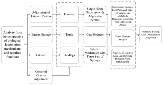
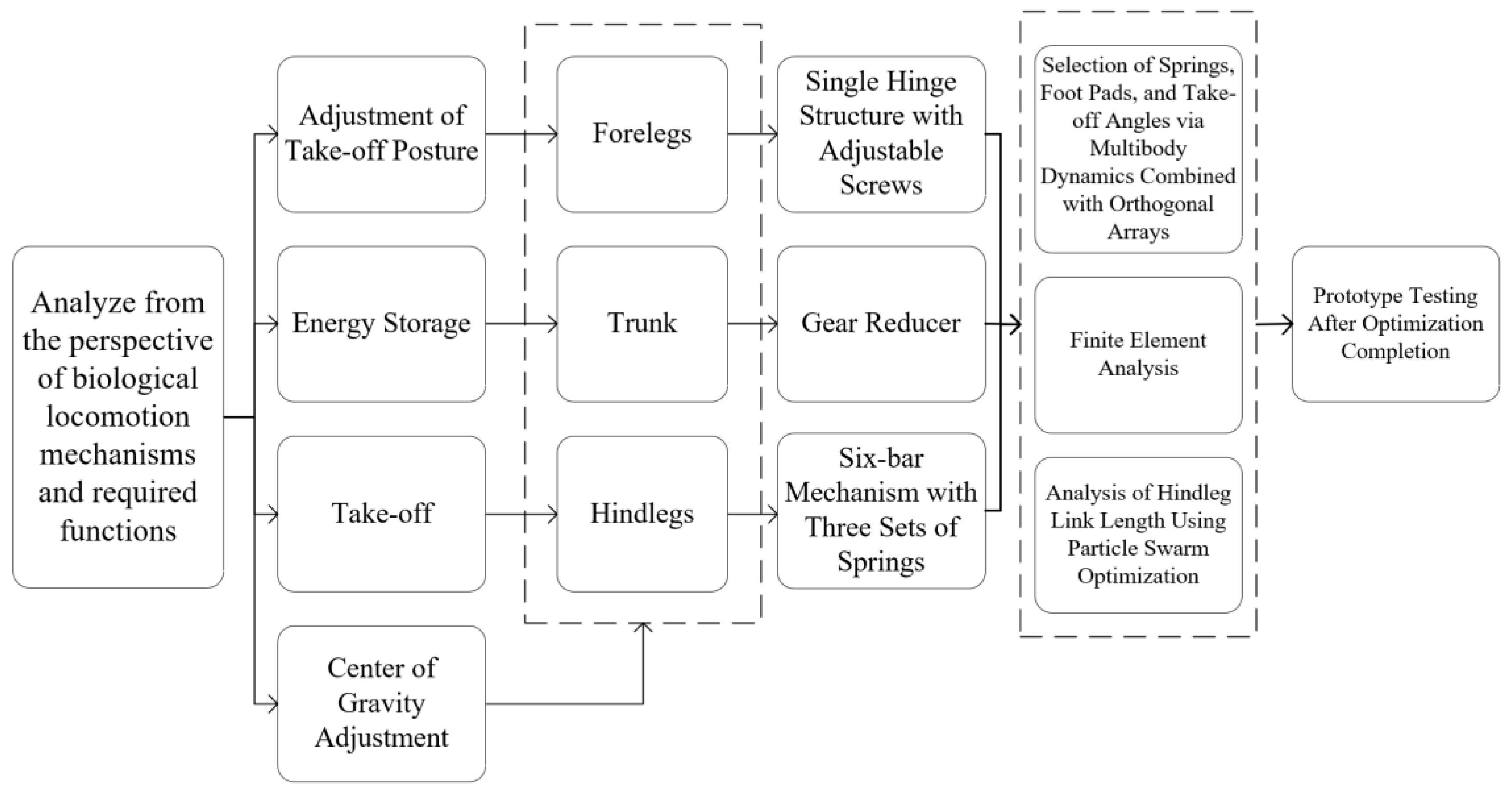
Figure 1 outlines a comprehensive technical roadmap for bionic mechanism research and mechanical system design, integrating theoretical analysis, functional development, performance optimization and motion consistency control to construct an integrated design framework. A modular design is adopted to divide the robot into forelegs, a trunk and hindlegs, realizing full space utilization and improved structural compactness.
Figure 1.
Design concept and technical roadmap of the bionic frog jumping robot.
First, the literature retrieval and case analysis are conducted for in-depth mechanism research, laying a theoretical foundation for clarifying biological motion mechanisms and guiding subsequent engineering implementation. On this basis, mechanism design is performed: integrating the energy output of the power supply module, key functional links (energy storage, takeoff, center of gravity and posture control, landing shock absorption) are systematically connected to form a complete motion execution chain. For structural and performance optimization, a dynamic model is first established for multi-body dynamics simulation [26] and finite element analysis [27]; subsequently, the orthogonal test method [28,29] and particle swarm optimization algorithm are synergistically used to realize iterative optimization of structural parameters, complete structural optimization and assembly design, and verify the final design effectiveness through experimental testing under real operating conditions. Meanwhile, for the motion transmission of bionic limbs (hind leg, trunk, foreleg), the cooperative operation of tension springs and reducers enables adaptive power output and precise motion transmission, effectively ensuring consistent motion characteristics between the mechanical system and the biological prototype.
2.2. Overall Structural Design
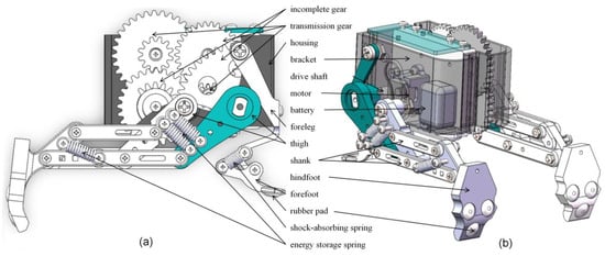
Figure 2 shows that the bionic frog robot features a modular layout integrating power supply, transmission, actuation and buffering functions, which leverages the efficient energy storage-release mechanism of frog hindlimbs—a biological characteristic realized by the coordinated movement of muscles and skeletal structures. By mimicking the physiological features of frogs, the overall structure is centered on the torso as the core support, connecting the hindlimb actuation module (for jumping power output) and the forelimb buffering module (for landing stability). A six-bar linkage mechanism is employed to simulate the skeletal structure of frog hindlimbs, while tension springs are used to mimic the elastic energy storage function of the semimembranosus and gastrocnemius muscles in the hindlimbs. Redundant components such as other muscle groups and neural structures are omitted for structural simplification. Core components (motor, power battery, transmission gears) are compactly arranged within the torso to optimize the distribution of the center of gravity, with the mass concentrated near the geometric center to enhance motion stability. The hindlimb (thigh, shank, hindfoot) replicates the lever structure of frog legs to enable efficient power transmission; the forelimb is integrated with shock-absorbing springs and rubber pads, which mimic the buffering effect of frog forelimbs during landing and thus effectively mitigate ground impact forces.
Figure 2.
Structural configuration and component labeling of the bionic frog jumping robot. (a) and (b) are different perspective views.
The core transmission system integrates incomplete gears and transmission gears to deliver intermittent, high-precision power output, ensuring the full compression of the hindlimb energy storage springs during energy accumulation and their rapid release thereafter. As the key power component, the energy storage springs are mounted on the hindlegs to replicate the elastic energy storage capability of frog leg muscles. The stiffness of the connecting rods is determined via dynamic simulations to balance jumping height against structural durability. Lightweight, high-strength materials are adopted for the housing and brackets, reducing the overall weight while preserving structural rigidity. Rubber pads fitted to the forefeet and hindfeet enhance ground adhesion during takeoff and landing—preventing slippage on complex terrains—and work in conjunction with shock-absorbing springs to form a multi-stage buffering system.
2.3. Load Test
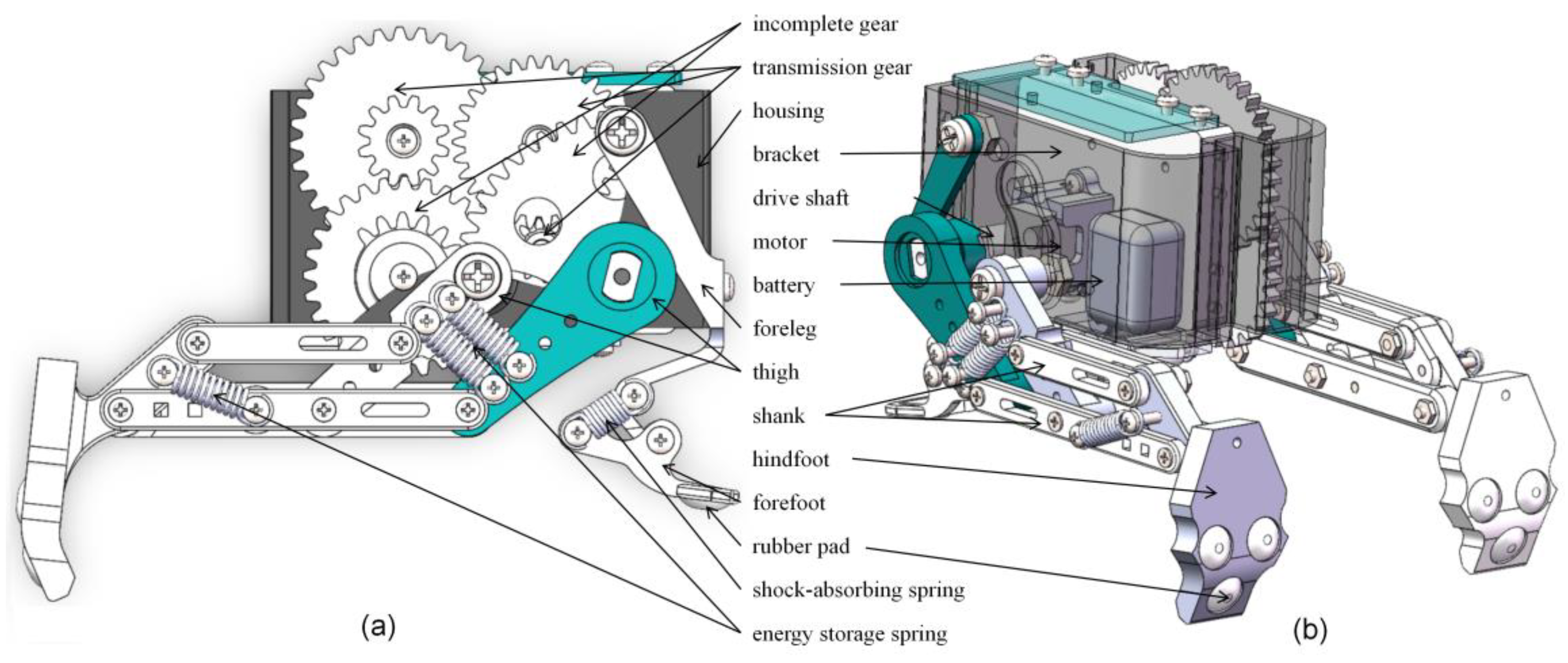
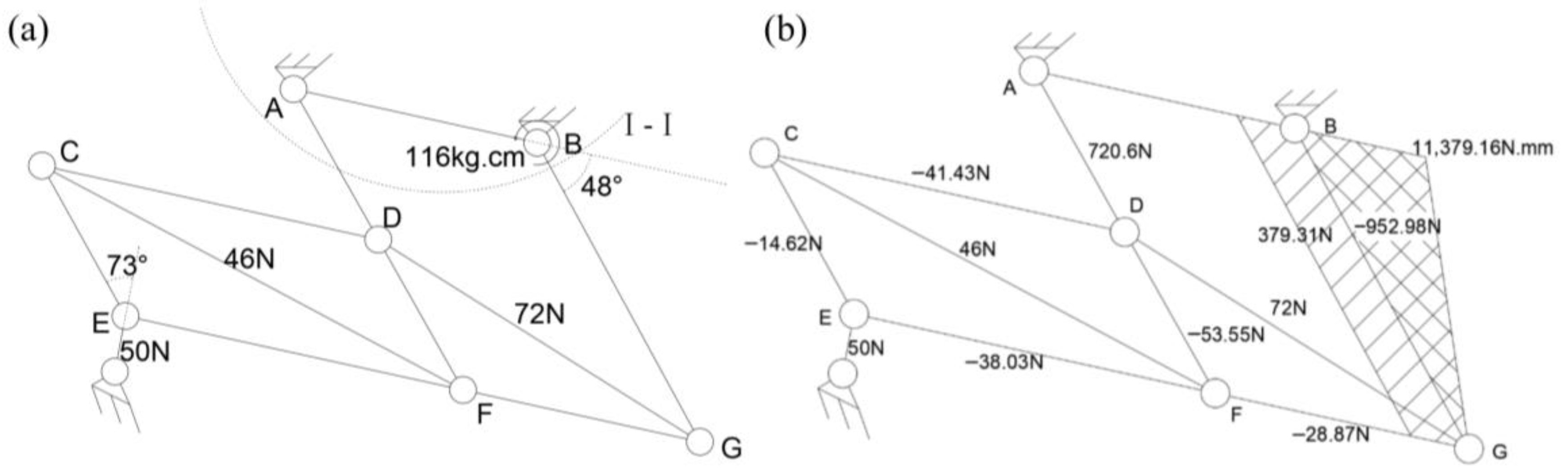
The transmission chain of the reducer assembly within the robot’s trunk was first calculated. Based on a safety factor of 1.2, the torque transmitted by the output shaft was then determined. Subsequently, the spring tension was incorporated into the system for comprehensive analysis, and a material mechanics model under the maximum load condition was established, as illustrated in Figure 3. In Figure 3a, the section labeled I-I corresponds to the frame component; material mechanics analysis was performed according to the force conditions depicted in Figure 3a, yielding the results presented in Figure 3b. The analysis revealed that the stress on rods BG and AD was significantly higher than that on the other connecting rods, necessitating structural reinforcement for these two components.
Figure 3.
Mechanical analysis of the hindlimb structure. (a) Free-body diagram of the hindlimb structure. (b) Axial force, shear force and bending moment diagram of the hindlimb linkages.
3. Simulation Based Structural Optimization
Based on the Lagrangian dynamic model established in Section 2, a mathematical model of motion performance was first derived to clarify the key relationship between structural parameters (notably shank length) and motion indices. The particle swarm optimization algorithm was then applied to optimize the shank length and determine its optimal dimensions. Subsequently, a multi-body dynamics simulation model under boundary conditions was constructed by considering the actual working conditions of the robot, and the effects of parameters such as spring stiffness on jumping performance were analyzed to identify key parameters. Finally, an orthogonal array was employed to design a multi-factor, multi-level test, and statistical analysis was conducted to determine the optimal parameter combination, which provides a theoretical basis for the fabrication of physical prototypes and the improvement of their performance. The detailed working cycle and kinematic/dynamic analysis of the robot are provided in Appendix A, and the detailed definition of the Particle Swarm Optimization (PSO) objective function for shank length optimization is presented in Appendix B.
3.1. Particle Swarm Optimization Analysis
Figure 4 depicts a simplified dynamic model established using MATLAB 2025. Among the model parameters, hind leg length introduces high complexity to kinematic simulations; thus, the particle swarm optimization (PSO) algorithm was employed to identify the optimal leg length. The algorithm parameters were carefully calibrated according to the mechanical structural characteristics of the bionic frog robot to ensure convergence and optimization accuracy. The specific PSO parameter settings were as follows: the particle population size was set to 50, the maximum number of iterations was 200, the inertia weight decreased linearly from 0.9 to 0.4 to balance global and local search capabilities, and the cognitive learning factor (c1) and social learning factor (c2) were both set to 2.0. The position search range of particles was constrained to [30, 70] mm (the feasible design range of shank length), and the velocity search range was limited to [−5, 5] mm/iteration to prevent algorithm divergence. The fitness function was defined as a comprehensive scoring model weighted by jumping height (0.4), jumping distance (0.3), energy efficiency (0.2), and structural stability (0.1), which aligns with the multi-objective optimization requirements of the jumping robot.
Figure 4.
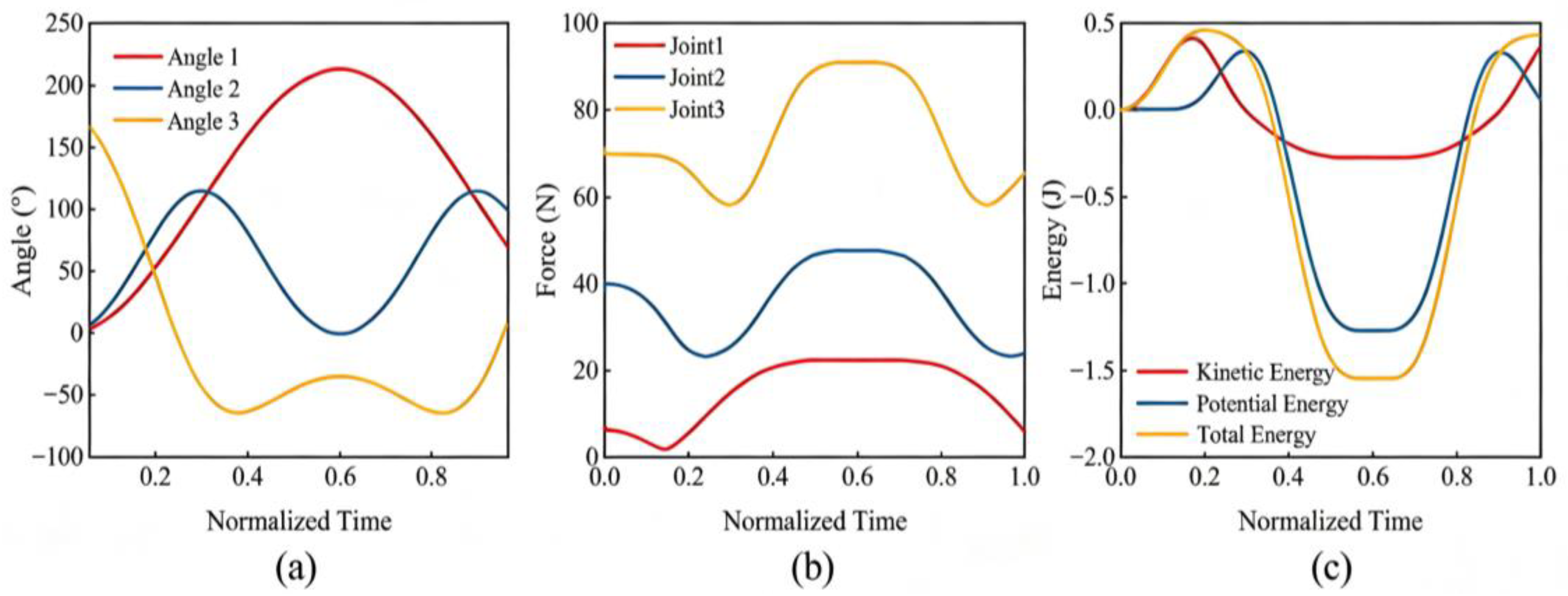
Dynamic performance curves of the bionic frog jumping robot with normalized time. (a) Joint angle curves. (b) Joint force curves. (c) Energy variation curves.
The objective function (i.e., fitness function) of the PSO algorithm was defined as a normalized weighted sum maximization function, which takes shank length as the sole design variable to comprehensively optimize the kinematic and dynamic performance (jumping height, distance) and structural stability of the robot. The detailed mathematical expression and parameter definitions of the objective function are provided in Appendix B.
Special attention was paid to shank length (the factor with the most significant impact on motion performance), while thigh length (a key factor affecting the robot’s center of gravity) was also considered. Although thigh length was preliminarily adjusted during structural design, its effectiveness in ensuring the symmetry and stability of the motion trajectory was further verified through subsequent analysis. Based on the aforementioned PSO parameter settings, the algorithm iteratively optimized the shank length and yielded an optimal value of 50 mm.
The optimization of shank length significantly enhanced the jumping performance of the robot: the physical prototype before optimization achieved a maximum jumping distance of only 350 mm, whereas the prototype fabricated with the optimized shank length (50 mm) attained a maximum jumping distance of 500 mm, representing a 42.86% increase in jumping distance. This improvement is attributed to the optimal shank length matching the force transmission characteristics of the six-bar linkage mechanism, which effectively improves the energy conversion efficiency of the tension spring and the take-off force of the hindlimb.
Meanwhile, the model was utilized to analyze the robot’s joint motion angles, joint forces, and energy loss characteristics. The results indicate that the three joints maintain good coordination throughout the jumping cycle without abrupt changes in motion; joint forces are uniformly distributed with no overload, verifying the reliable load-bearing performance of the structure. Energy analysis reveals that the jumping process requires significantly more potential energy than kinetic energy, and the spring’s energy storage capacity during the energy accumulation phase still has room for improvement—providing guidance for the subsequent optimization of the energy storage mechanism.
3.2. Multi-Body Dynamics and Orthogonal Array Analysis
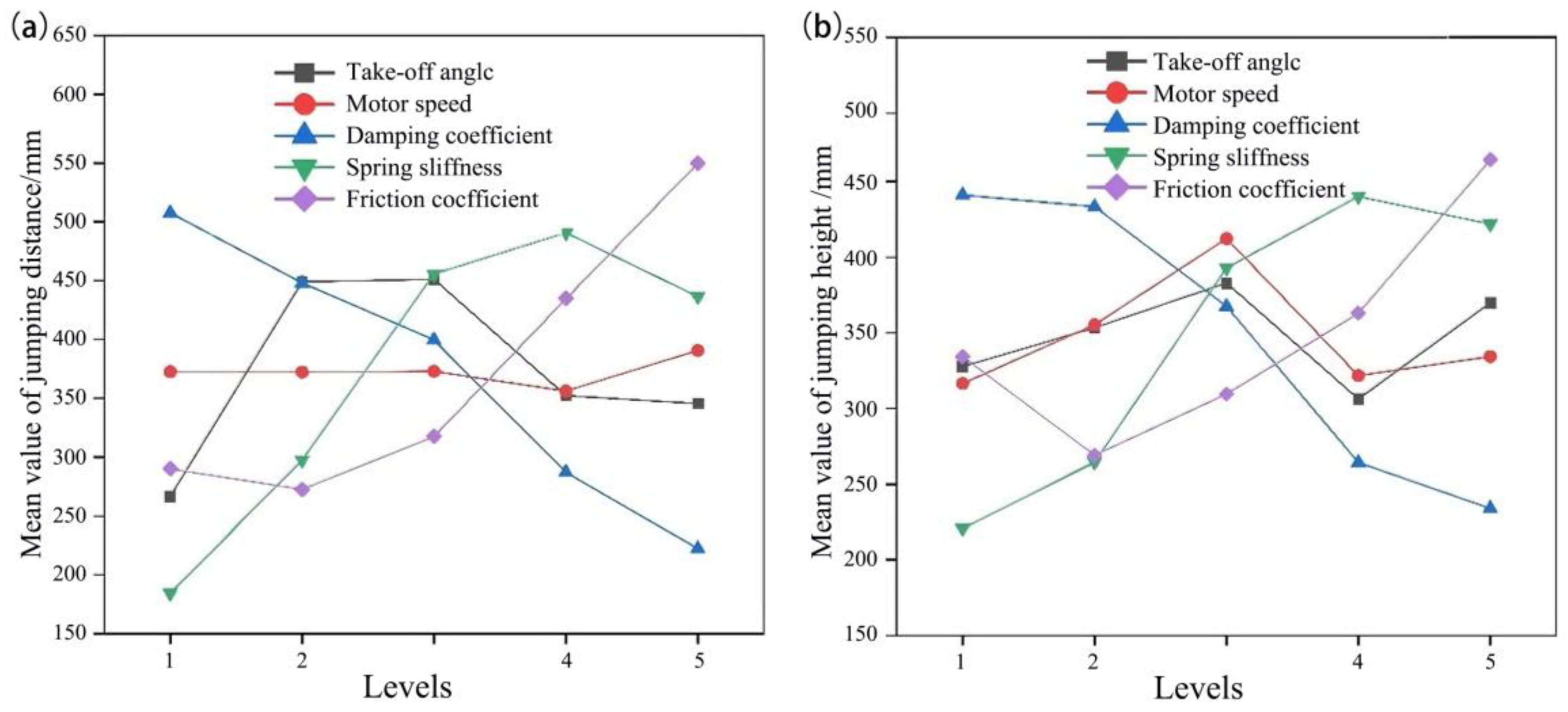
The entire model was imported into a simulation platform to perform multi-body dynamics analysis. With air resistance and energy losses in the structural transmission system neglected, simulations were conducted to evaluate the robot’s jumping performance metrics during jumps on an acrylic plate. The specific values selected for the five key parameters (take-off angle, motor speed, damping coefficient, spring stiffness, and friction coefficient) are detailed in Table 1. The effects of these key parameters (see Figure 5) on jumping performance were analyzed to identify the optimal parameter combination that maximizes the robot’s jumping performance.
Table 1.
Factor and level table for orthogonal experiment of jumping performance parameters.
Figure 5.
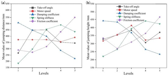
Mean main effect plots of jumping performance from range analysis. (a) Mean effect plot of jump distance. (b) Mean effect plot of jump height.
A range analysis was performed on the parameters investigated in the orthogonal experiment. As illustrated in the main effect plots of the mean jump distance and jump height presented in Figure 5, increasing the spring stiffness and friction coefficient generally led to a gradual increase in both jump distance and jump height. Conversely, an increase in the damping coefficient resulted in a gradual decrease in both performance metrics. With increasing motor speed, the jump distance remained relatively unchanged, whereas the jump height exhibited a trend of first increasing and then decreasing. Likewise, both evaluation indicators increased initially and then decreased as the take-off angle was increased.
Furthermore, an analysis of variance was conducted on the parameters evaluated in the orthogonal experiment. By synthesizing the findings from these two analytical methods, a parameter validation study was performed to determine the optimal parameter combination, as summarized in Table 2. Special attention was devoted to the take-off angle, as it was identified as the most critical factor influencing jumping performance.
Table 2.
Verification of the optimal parameter combination for the bionic frog jumping robot.
4. Load Test and Finite Element Analysis
Finite Element Analysis
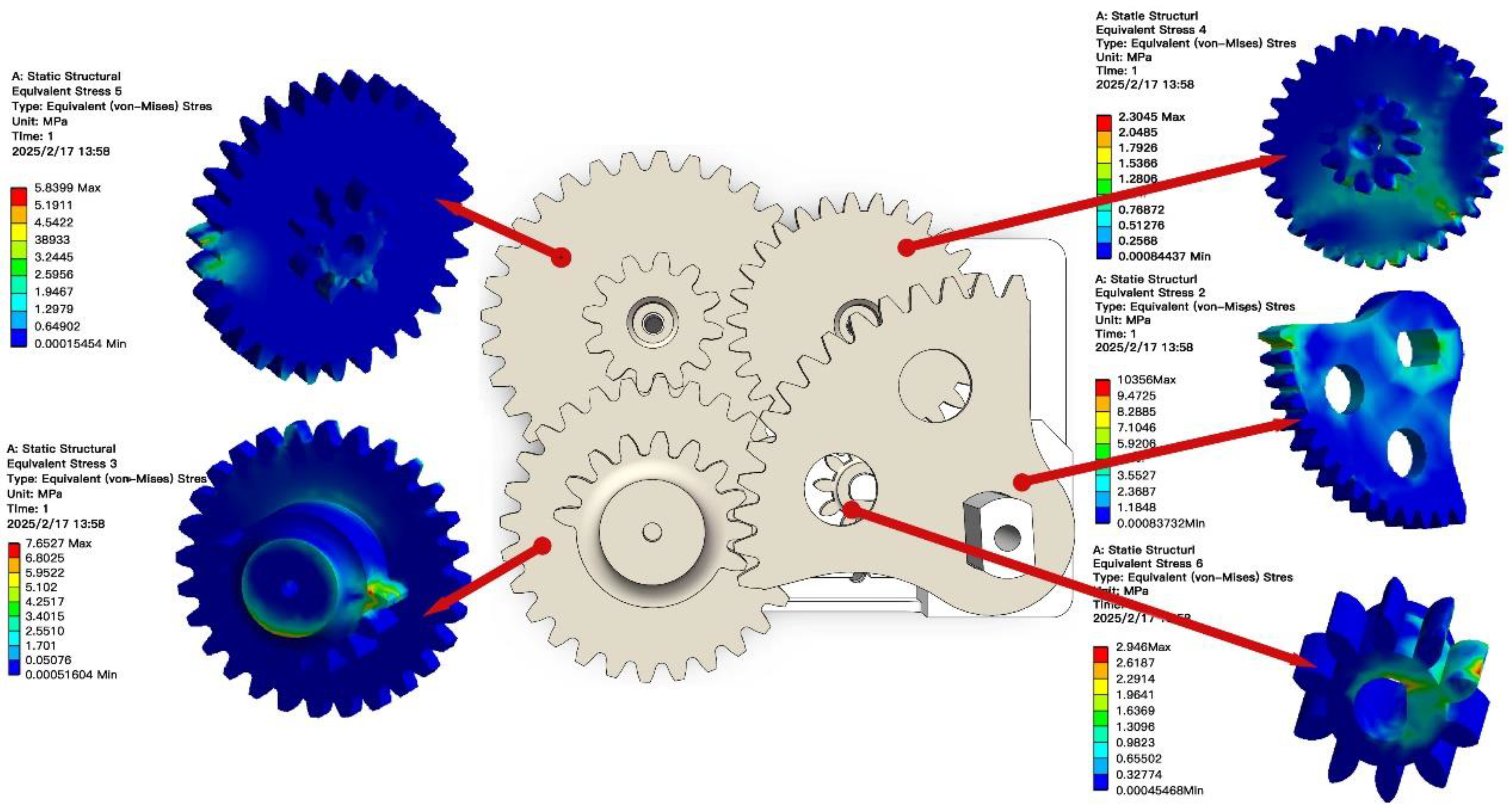
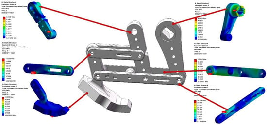
The finite element analysis (FEA) of the robot structure was carried out under the final stage of hindlimb energy storage—the critical working condition with the maximum load before take-off, and the loading cases and boundary conditions of the FEA were determined based on the material mechanics model of the hindlimb structure under maximum load in Section 2.3 (as shown in Figure 3), including the axial forces, shear forces, bending moments and torque acting on each connecting rod and key joints.
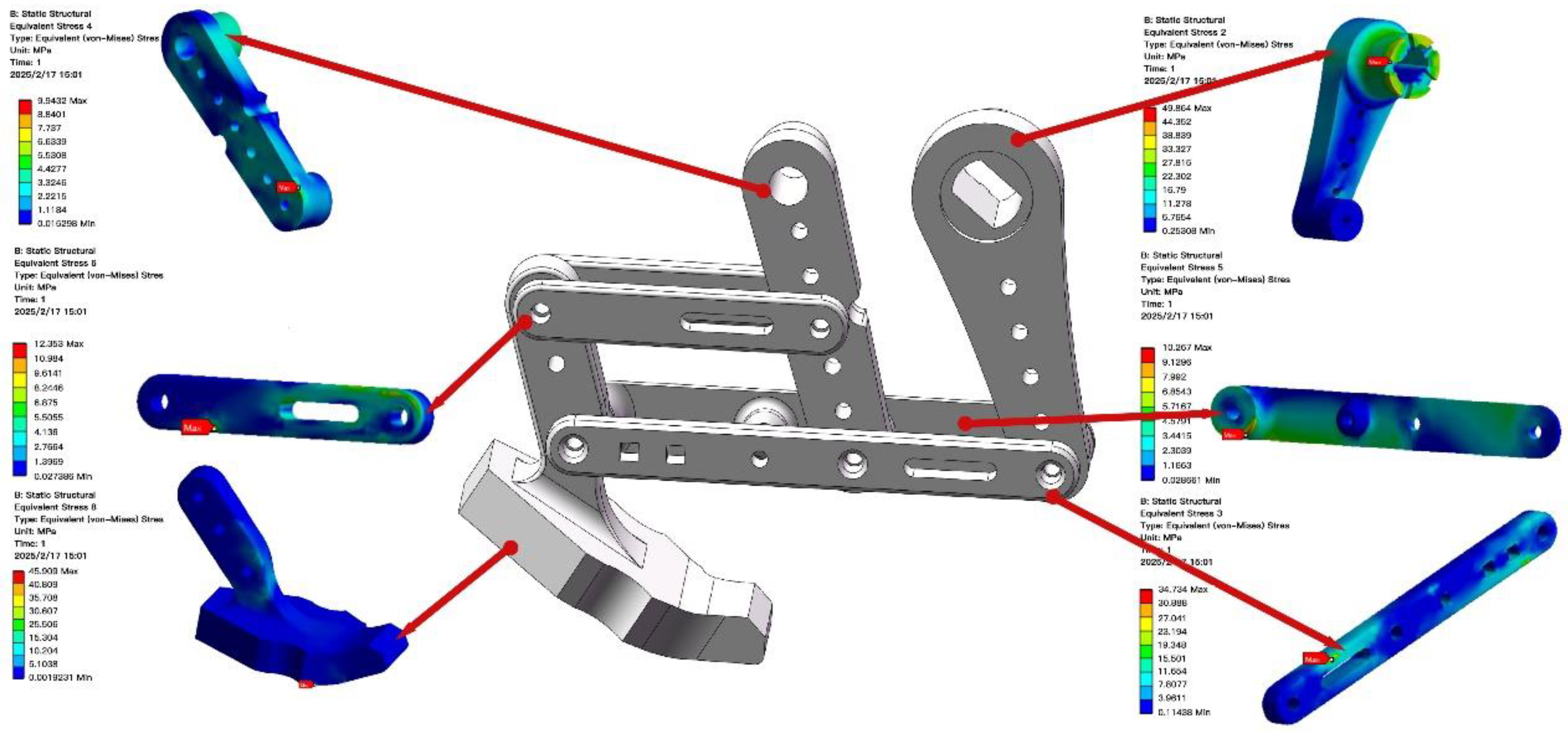
A material mechanics analysis was conducted on the structure. Among the components, structures such as connecting rods and gears were made of carbon fiber-reinforced PLA. In Figure 6 and Figure 7, the loads on the left and right parts were both lower than their yield strength of 50 MPa [30]. This verifies that the structure exhibits favorable structural strength and excellent durability, fully meeting the mechanical performance requirements for the jumping robot’s operation.
Figure 6.
Finite element analysis stress nephogram of the gear components.
Figure 7.
Static analysis stress distribution contour map of the linkage components.
5. Experimental Studies
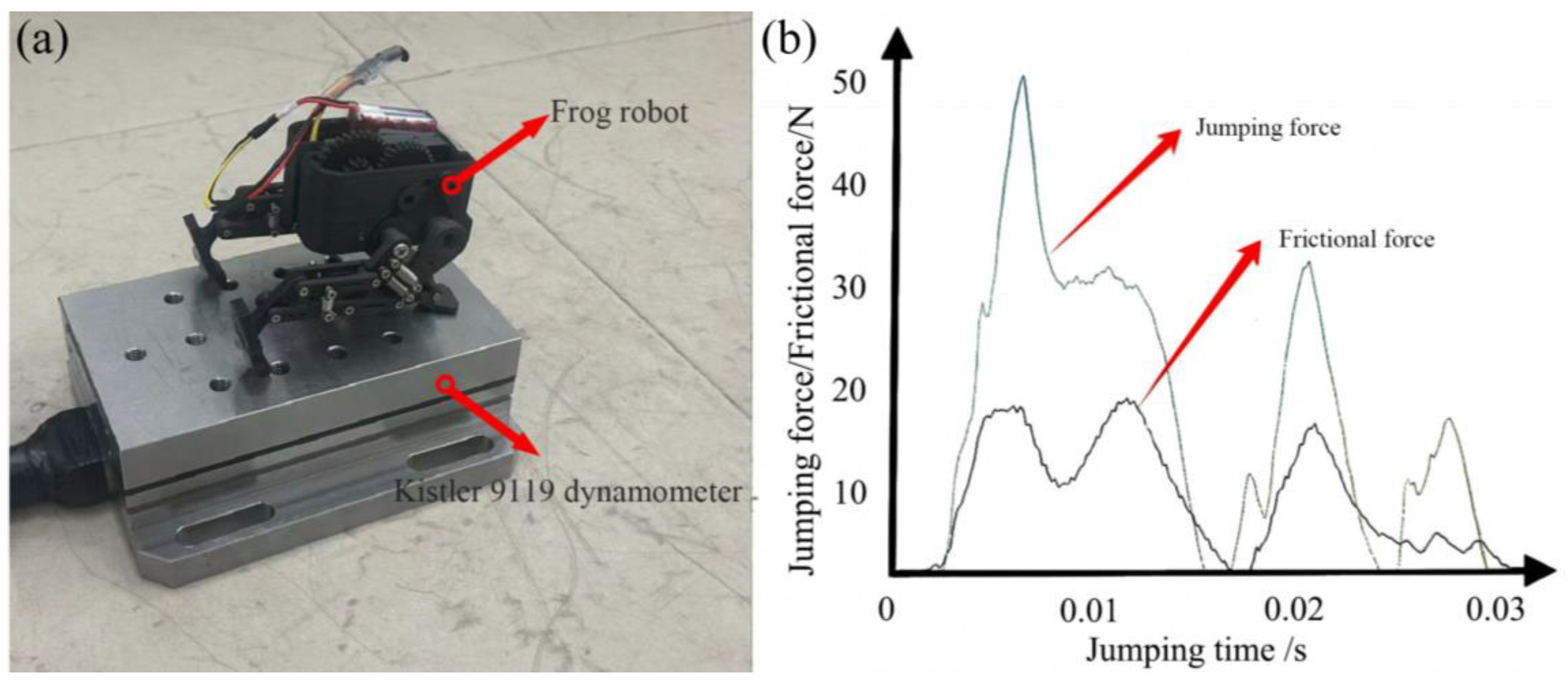
Jumping and ground thrust tests were conducted on the physical prototype, with the experimental setup illustrated in Figure 8. As shown in Figure 8a, a force sensor was used to measure the take-off thrust force of the prototype, which was determined to be 50 N. Jumping tests were performed on a tiled surface; a camera was placed horizontally parallel to the ground and on the lateral side of the prototype to record each jump process. The maximum jumping height and landing position of the prototype were extracted from the recorded video footage, and the corresponding jump distances were measured manually using a ruler. Over a dozen physical tests were carried out for repeatability, yielding a minimum jumping distance of 430 mm, a maximum of 520 mm, and most measured values clustering around 500 mm. The experimental results were highly consistent with those obtained from the simulation analysis; the key parameters of the physical prototype are summarized in Table 3, while the detailed components, material selections and corresponding processing methods of the prototype are listed in Table 4. A Supplementary Video S1 is provided to demonstrate the jumping performance and movement characteristics of the proposed bionic frog robot.
Figure 8.
Ground thrust test of the physical prototype. (a) Experimental setup. (b) Measured force-time curve of pedal thrust and frictional force.
Table 3.
Main technical parameters of the bionic frog jumping robot prototype.
Table 4.
Bill of materials and processing methods of the key components.
6. Conclusions
- (1)
- A frog-inspired jumping robot was designed by integrating biological locomotion mechanisms with engineering design. The prototype with a mass of 150 g achieves 50 N ground thrust, 380 mm jumping height, and 500 mm maximum horizontal distance, through systematic optimization and validation.
- (2)
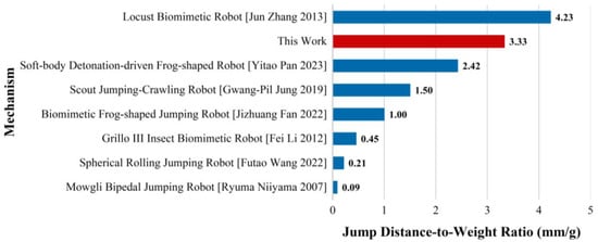
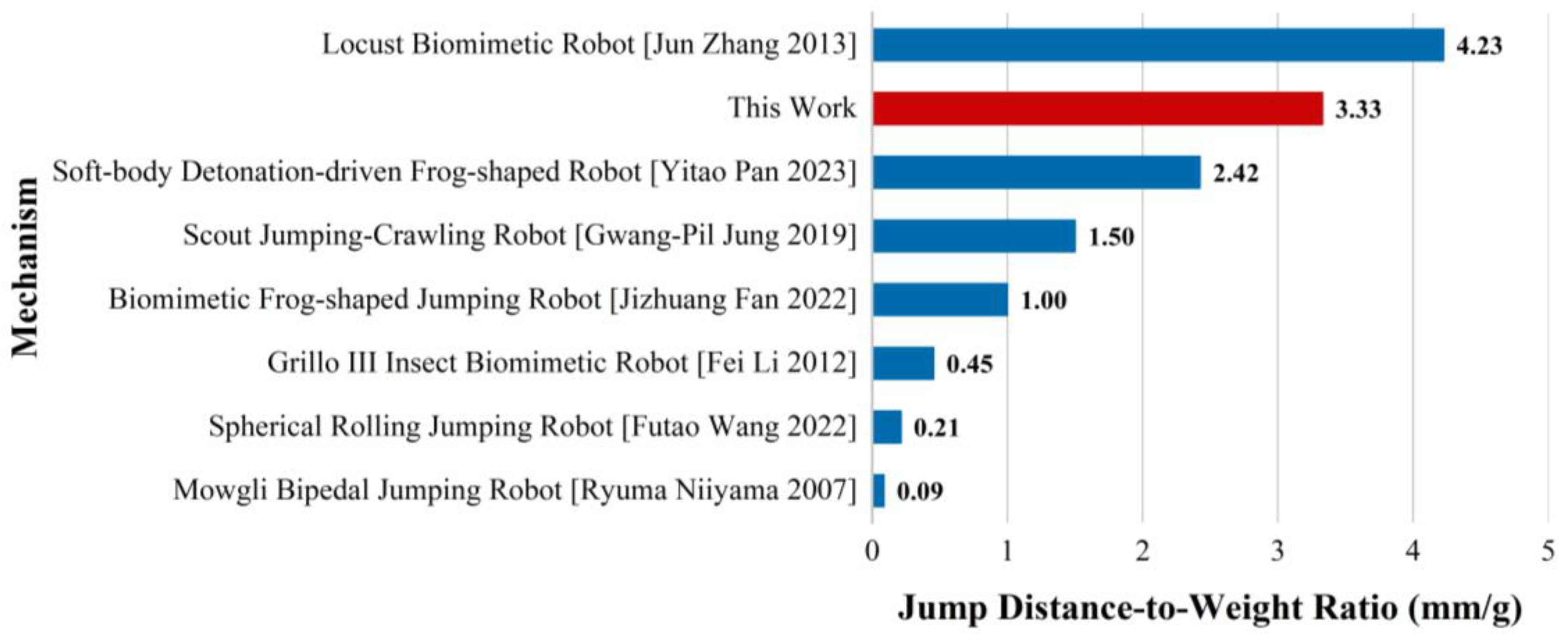
- The design innovatively balances structural compactness, lightweight, and jumping performance, simplifying the mechanical structure while ensuring efficient energy conversion and stable motion transmission—providing a practical prototype for biomimetic robot development. Figure 9 presents previously proposed well-known miniature hopping mechanisms along with their excellent jumping performance, with the jump distance-to-mass ratio labeled. It can be seen that among hopping mechanisms of similar size, the results of this study exhibit relatively outstanding performance.Figure 9. Comparison of jump distance-to-mass ratio for typical miniature hopping robots, including: Locust biomimetic robot [31], soft-body detonation-driven frog-shaped robot [24], Scout jumping-crawling robot [32], biomimetic frog-shaped jumping robot [13], Grillo III insect biomimetic robot [16], spherical rolling jumping robot [33], and Mowgli bipedal jumping robot [4].
- (3)
- The proposed design framework and optimization method offer valuable insights for biomimetic robotics. Its modular configuration and efficient energy storage–release mechanism show great application potential in disaster relief, planetary exploration, and narrow-space tasks, paving the way for enhanced adaptability of mobile robots in complex scenarios. In addition, the quantitative experimental data obtained from the bionic design and prototype testing of this robot also supplements engineering experimental insights for the study of frog hindlimb locomotion biomechanics, realizing the combination of bionic robot engineering design and biological locomotion mechanism research.
- (4)
- This study has certain limitations that need to be further addressed in subsequent research. The primary limitation is that the bionic frog jumping robot cannot ensure the recovery of the initial take-off posture after each jumping movement, which restricts the continuity of repeated jumping operations in practical applications. This issue arises from the lack of a dedicated mechanical posture reset mechanism in the current structural design; the landing impact leads to slight deviations in the robot’s center of mass and limb positions, making it impossible to accurately return to the preset take-off state.
Subsequent research will focus on optimizing the structural design by adding a compact and lightweight posture reset mechanism, which will realize the automatic reset of the robot’s limbs and center of mass after landing, thus improving the continuity and practicality of the jumping motion. In addition, the energy storage system of the current prototype adopts tension springs with fixed stiffness, and the follow-up research will explore a multi-stiffness adjustable energy storage structure to realize the dynamic adjustment of jumping height and distance for different application scenarios.
Supplementary Materials
The following supporting information can be downloaded at: https://www.mdpi.com/article/10.3390/machines14030325/s1, Video S1: Demonstration of the jumping motion and landing posture of the bionic frog robot prototype.
Author Contributions
Conceptualization, L.Y. and F.J.; methodology, L.Y. and F.J.; software, Z.S.; validation, Z.S.; formal analysis, Z.S.; investigation, Z.S.; resources, L.Y. and F.J.; data curation, Z.S.; writing—original draft preparation, Z.S.; writing—review and editing, L.Y. and F.J.; visualization, Z.S.; supervision, L.Y. and F.J.; project administration, L.Y. and F.J.; funding acquisition, L.Y. and F.J. All authors have read and agreed to the published version of the manuscript.
Funding
This research received no external funding. The APC was funded by Huaqiao University.
Data Availability Statement
The data that support the findings of this study are available from the corresponding author upon reasonable request.
Conflicts of Interest
All authors have disclosed that they have no relevant conflicts of interest. The content of this manuscript has not been previously published, either in whole or in part, and is not currently under consideration by any other journal. All authors are aware of the manuscript’s content and are responsible for its accuracy and integrity.
Appendix A. Working Cycle and Kinematic and Dynamic Analysis
As shown in Figure A1, the working cycle of the bionic frog jumping robot consists of two interconnected phases: energy storage and energy release, with the rotation angle θ of the driving link serving as the core input parameter that governs the displacement of the end point H. During the energy storage phase, the motor-driven incomplete gear engages with the transmission gear, and the energy storage spring is compressed as the hindlimb rotates. The X and Y displacements of point H are given by the derived equations:
Among the parameters, and represent the coordinates of hinge , while and denote the coordinates of hinge . and correspond to the coordinates of point H—the equivalent ground contact point. stands for the length of the driving link, and is the rotation angle of the driving link; the derivative of reflects the kinematic coupling effect between the interconnected links of the mechanism.
During the energy storage phase, the motor-driven incomplete gear engages with the transmission gear, and the energy storage spring is compressed as the hindlimb rotates. Based on the geometric constraint relationship of the six-bar linkage mechanism, the kinematic displacement equations of the end point H (X and Y directions) for the bionic frog robot are derived as follows:
The parameters in the above two kinematic equations all represent the key geometric and motion parameters of the six-bar linkage mechanism in the global coordinate system, where and are the horizontal and vertical coordinates of hinge in the global coordinate system, and and are the horizontal and vertical coordinates of hinge , both of which are fixed structural parameters of the robot’s hindlimb six-bar linkage mechanism and remain unchanged during the motion process. and are the horizontal and vertical displacements of point H, which is the equivalent ground contact point of the robot’s hindfoot and the core motion output point of the jumping mechanism, and the change in its coordinates directly determines the take-off trajectory of the robot. is the fixed length of the driving link of the six-bar linkage mechanism, which is a key structural dimension affecting the force transmission efficiency, and is the rotation angle of the driving link controlled by the motor and reducer, which is the core input motion parameter of the hindlimb movement. The time derivative of can reflect the kinematic coupling effect between the interconnected links of the six-bar linkage mechanism, and this coupling effect is the key to ensuring the coordinated movement of each part of the robot’s hindlimb during the energy storage phase, and it also ensures the synchronous compression of the energy storage spring with the rotation of the driving link.
Furthermore, the coordinates of hinge D are obtained by solving Equations (A3) and (A4)—these two equations are derived from the fixed-length constraints of links AD and CD. Similarly, the coordinates of point H are calculated by solving Equations (A5) and (A6), which are established based on the geometric constraints of the execution links (including the fixed length of and the horizontal alignment of point E and F.
Figure A1.
Energy storage and release process of the bionic jumping mechanism. (a,b) Physical structural states. (c,d) Corresponding kinematic schematic diagrams with key point coordinates.
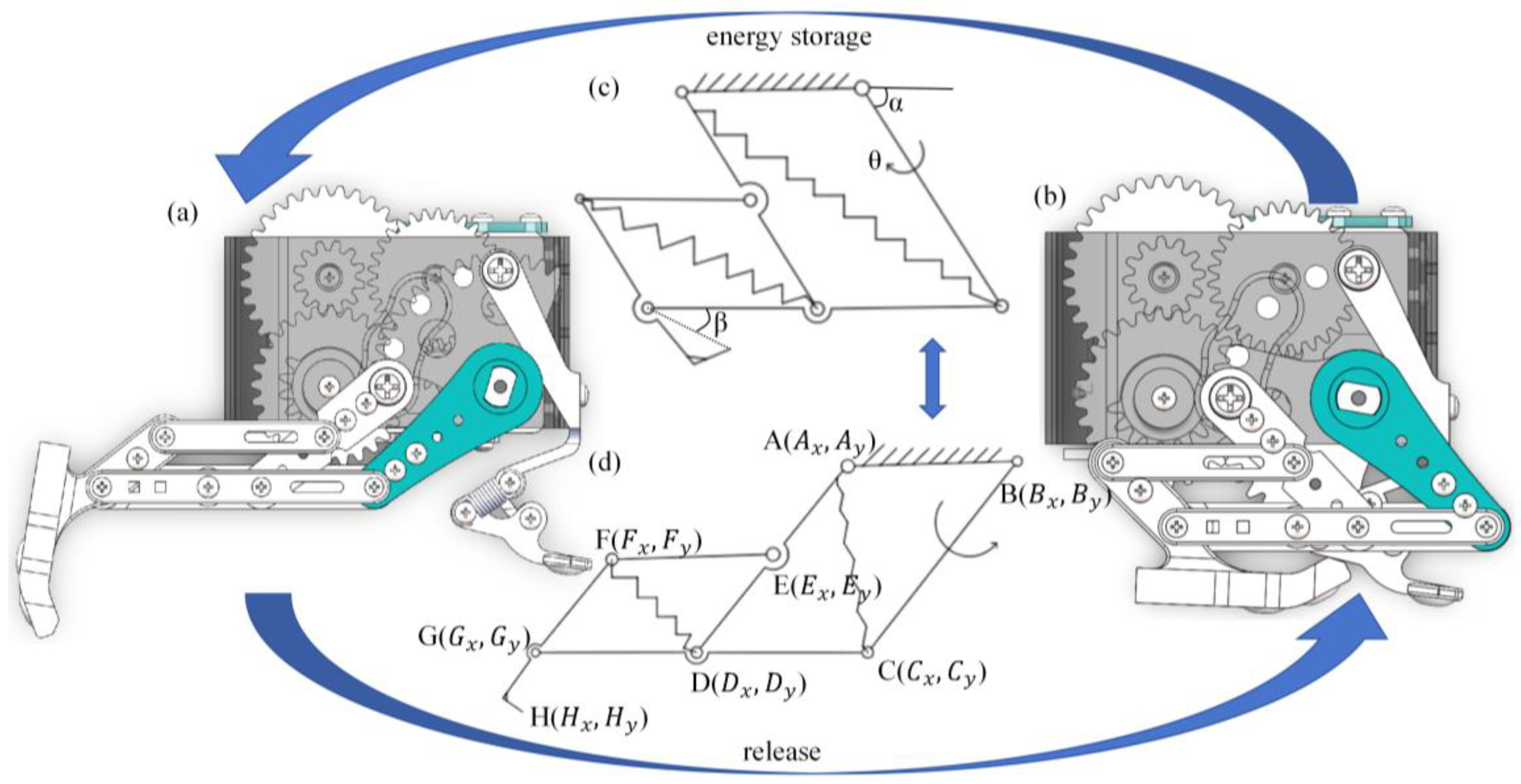
Gear disengagement triggers takeoff: stored elastic potential energy rapidly converts to kinetic energy, driving hindlimb extension and accelerating H-point displacement to provide horizontal and vertical forces. Post-takeoff, the robot follows a parabolic trajectory; the forelimb buffer module absorbs landing impact, while the hindlimb retracts passively. The driving link resets to its initial position, and gear re-meshing readies the robot for consecutive jumps.
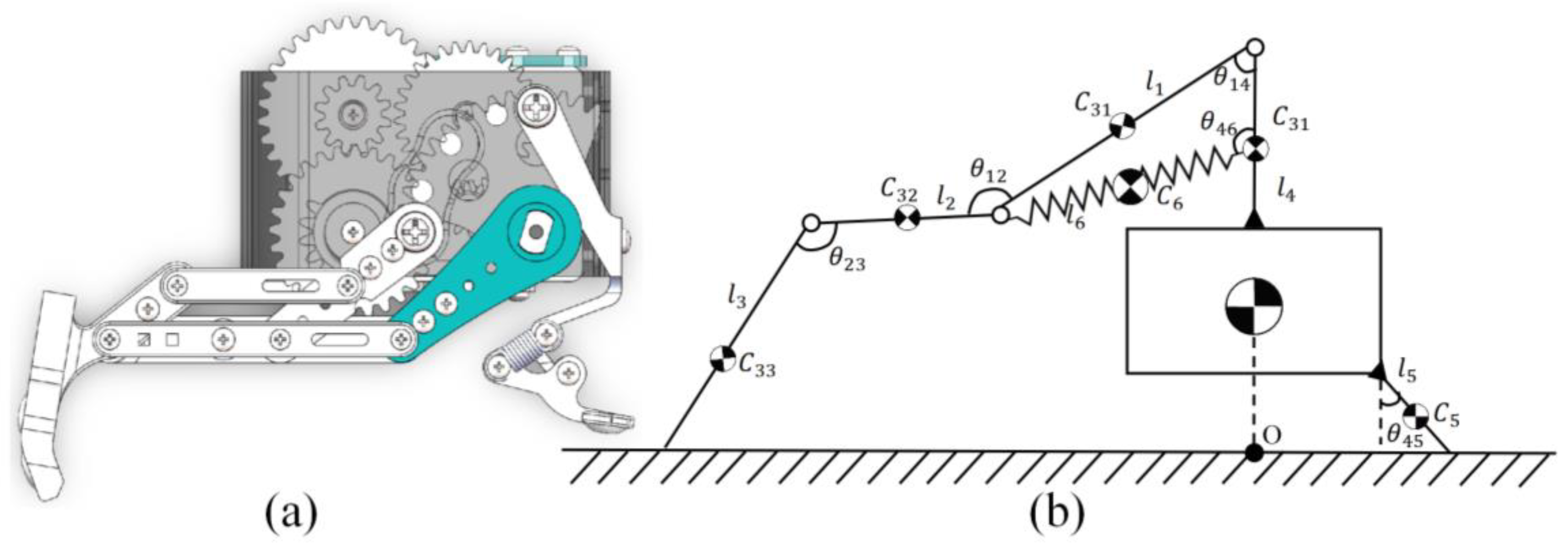
In this study, focusing on the six-bar force-amplifying mechanism of the frog-inspired jumping robot (comprising thigh link , shank link , foot link , torso support link , forelimb buffer link , and spring connection link and the spring energy storage structure, we refine the Lagrangian dynamic model. By analyzing the relative rotational and displacement constraints among the six links during the takeoff process, we clarify the motion coupling relationships between them. Adopting the coordinate system with as the origin, the mechanism is simplified into a model for dynamic analysis of the ejection process, as illustrated in Figure A2.
In this model, denotes the center of mass (COM) of and , is the COM of , is the COM of , is the COM of , and is the COM of the spring. The angles , , , , and represent the relative rotations between & , & , & , & , and & , respectively.
Figure A2.
Lagrangian dynamic model of the ejection process for the six-bar force-amplifying mechanism. (a) Simplified structural schematic. (b) Dynamic modeling diagram with centroid and relative angle definitions.
Based on the Lagrangian dynamic model of the six-bar force-amplifying mechanism of the bionic frog robot, we derive the general form of the Lagrangian dynamic differential equation for the bionic jumping mechanism, which is used to describe the inertial coupling characteristics and force-torque transmission rules of each link of the six-bar mechanism during the ejection take-off phase, and the specific form is shown in Figure A3.
Figure A3.
General form of the dynamic differential equation for the bionic jumping mechanism.
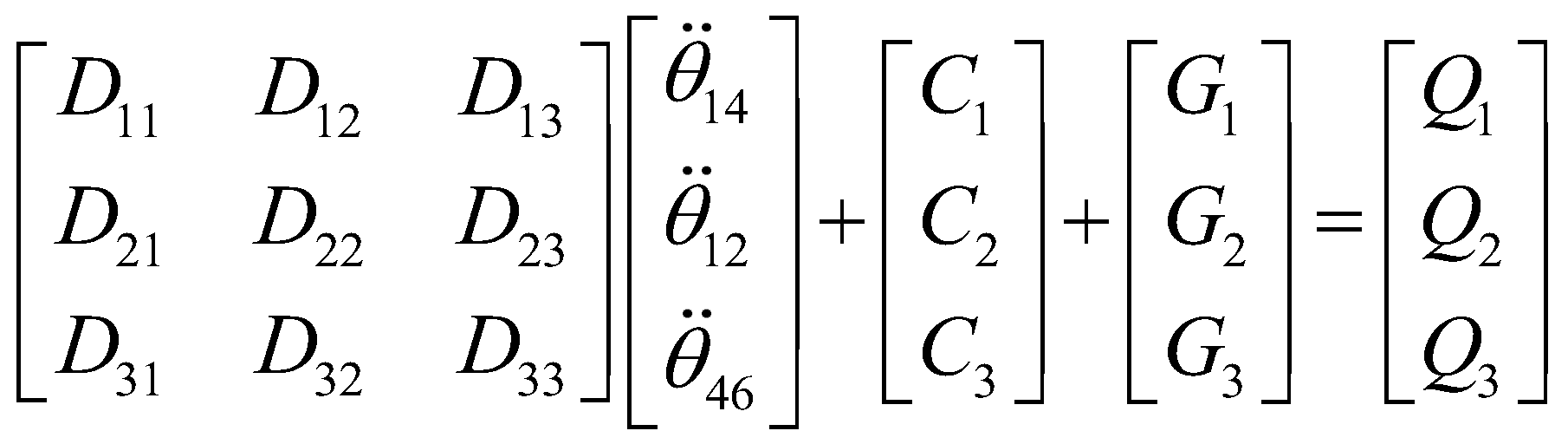
The core variables in this dynamic differential equation general form are the key parameters to characterize the dynamic characteristics of the six-bar force-amplifying mechanism, where L is the Lagrangian function of the system, which is the difference between the total kinetic energy T and the total potential energy V of the six-bar linkage mechanism. The total kinetic energy T includes the rotational kinetic energy and translational kinetic energy of all links of the six-bar mechanism, and its value changes with the relative rotation and displacement of each link during the ejection phase. The total potential energy V contains the gravitational potential energy of the entire mechanism and the elastic potential energy of the energy storage spring, and the elastic potential energy is the main power source for the robot’s take-off. is the generalized coordinate of the system, which is selected as the relative rotation angle between the key links of the six-bar mechanism in this study, and is the first derivative of the generalized coordinate, that is, the angular velocity of the relative rotation of the links, which directly reflects the motion speed of each link during the ejection process. is the generalized force vector of the system, which integrates all external excitations acting on the mechanism, including the motor torque transmitted through the reducer, the reaction torque generated at each joint of the links due to relative motion, and the ground contact force received by the hindfoot during the take-off phase. Each component of the generalized force vector is closely related to the motion state of the mechanism, and its change directly affects the dynamic response of the robot during the ejection take-off phase.
In the equation (Figure A3), is the mass-inertia matrix term, reflecting the inertial coupling characteristics among generalized coordinates.
is the coupling term vector, including centrifugal and Coriolis force terms related to generalized velocities. is the gravitational term vector, derived from the partial derivatives of the system’s gravitational potential energy with respect to generalized coordinates. is the generalized force vector, covering external excitations such as motor torques and joint interaction moments. The relative angle between link 1 and link 4, between link 1 and link 2, and between link 4 and link 6 are selected as generalized coordinates.
Therefore, we have:
In the above equations, the parameters are clarified as follows:
For link motion and posture parameters, represents the contact segment length between foot link 3 and the ground, with its value determined jointly by the structural dimensions of the foot and the robot’s takeoff posture.
Regarding inertial and mass parameters, , , , respectively refer to the moments of inertia of thigh link 1, shank link 2, torso support link 4, and spring connection link 6 about their own centroids; , , , are the masses of the above four links; , , , , stand for the distances from the centroids of thigh link 1, shank link 2, torso support link 4, forelimb buffer link 5, and spring connection link 6 to their corresponding joints.
For force and torque parameters, is the torque exerted on thigh link 1 by the motor through a reducer; , , are the reaction torques at the knee joint, spring connection joint, and ankle joint respectively; is the horizontal reaction force applied by forelimb buffer link 5 to torso support link 4; is the vertical acceleration of the centroid of shank link 2, generated by the coupling of the rotational motion of thigh link 1 and the relative motion of shank link 2; and are the horizontal and vertical contact force densities at any point on the contact segment of foot link 3, directly affecting the force transmission efficiency during ground-pushing.
For spring-related parameters, k is the stiffness coefficient of the energy storage spring, is the actual length of the spring, and is the original length of the spring; is the bending stiffness coefficient of foot link 3, used to describe the elastic deformation behavior of the foot when in contact with the ground.
Based on the force analysis of the six-bar force-amplifying mechanism and the physical characteristics of the energy storage spring, we derive the key force calculation equations for the bionic jumping mechanism including spring elastic force, joint axial force and foot ground-pushing force as follows:
The supplementary formulas for spring elastic force (), joint axial force (), foot ground-pushing force (), and model verification are presented above.
The established basic Lagrangian dynamic model simplifies the spring into a single equivalent component. This model not only clarifies the calculation logic of key variables in the six-bar force-amplifying mechanism and the correlation between parameters, but also provides a reliable theoretical basis for guiding further mathematical modeling and simulation of the frog-inspired jumping robot.
Appendix B. Objective Function of Particle Swarm Optimization (PSO) Algorithm
To optimize the shank length of the bionic frog jumping robot and achieve multi-objective improvement of the robot’s jumping height, jumping distance, energy efficiency and structural stability, the fitness function of the Particle Swarm Optimization (PSO) algorithm for shank length optimization is defined as a normalized weighted sum maximization function, and the mathematical expression is shown in Figure A4.
Figure A4.
Mathematical expression of the PSO objective function for shank length optimization.

In the formula, denotes the comprehensive objective function value with a range of , and represents the shank length which serves as the sole design variable with a feasible range of ; , , , and are the weight coefficients corresponding to jumping height, jumping distance, energy efficiency, and structural stability, respectively, and these coefficients are determined based on the engineering priority of the robot’s performance indicators. stands for the normalized jumping height, where is the actual jumping height of the robot when the shank length is , and is the maximum theoretical jumping height within the design range of the shank length; refers to the normalized jumping distance, where is the actual jumping distance of the robot with shank length , and is the maximum theoretical jumping distance within the design range of the shank length. represents the energy efficiency of the robot with a range of , which is calculated by the ratio of the robot’s output kinetic energy to the total input energy (including motor energy and spring elastic potential energy); is the structural stability of the robot with a range of , synthesized by the static stability (based on the center of gravity position and support polygon of the mechanism) and dynamic stability (based on the mass distribution of the robots).
References
- Yoshikawa, K.; Otsuki, M.; Kubota, T.; Maeda, T.; Ushijima, M.; Watanabe, S.; Sakamoto, K.; Kunii, Y.; Umeda, K. A New Mechanism of Smart Jumping Robot for Lunar or Planetary Satellites Exploration. In Proceedings of the 2017 IEEE Aerospace Conference; IEEE: Big Sky, MT, USA, 2017; pp. 1–9. [Google Scholar]
- Kim, S.-K.; Park, S.-H. A Study on Intelligent Combat Robot Systems for Future Warfare. Int. J. Adv. Cult. Technol. 2023, 11, 165–170. [Google Scholar] [CrossRef]
- Jiang, J.; Zeng, Y.; Yu, X.; Wu, D.; Guo, Y. Hopping Robot: Current Status and Future Perspectives. Recent Pat. Mech. Eng. 2021, 14, 440–455. [Google Scholar] [CrossRef] [Scilit]
- Niiyama, R.; Nagakubo, A.; Kuniyoshi, Y. Mowgli: A Bipedal Jumping and Landing Robot with an Artificial Musculoskeletal System. In Proceedings of the 2007 IEEE International Conference on Robotics and Automation, Rome, Italy, 10–14 April 2007; IEEE: Rome, Italy, 2007; pp. 2546–2551. [Google Scholar]
- Liu, G.-H.; Lin, H.-Y.; Lin, H.-Y.; Chen, S.-T.; Lin, P.-C. A Bio-Inspired Hopping Kangaroo Robot with an Active Tail. J. Bionic Eng. 2014, 11, 541–555. [Google Scholar] [CrossRef] [Scilit]
- Nguyen, Q.-V.; Park, H.C. Design and Demonstration of a Locust-like Jumping Mechanism for Small-Scale Robots. J. Bionic Eng. 2012, 9, 271–281. [Google Scholar] [CrossRef] [Scilit]
- Chen, D.; Yin, J.; Zhao, K.; Zheng, W.; Wang, T. Bionic Mechanism and Kinematics Analysis of Hopping Robot Inspired by Locust Jumping. J. Bionic Eng. 2011, 8, 429–439. [Google Scholar] [CrossRef] [Scilit]
- Liu, J.; Ma, G.; Zhang, T.; Shan, X.; Kang, R.; Zheng, R.; Liu, H. Untethered Soft Crawling Robot Based on Origami Inspired Soft-Rigid Hybrid Actuator. J. Bionic Eng. 2025, 22, 1071–1084. [Google Scholar] [CrossRef] [Scilit]
- Gao, H.; Shan, K.; Wang, S.; Han, L.; Yao, J.; Yu, H. An Alternating Optimization Approach Integrating Linkage Design with Motion Planning for Jumping Robot. Mech. Mach. Theory 2023, 185, 105332. [Google Scholar] [CrossRef] [Scilit]
- Pan, Y.; Fan, J.; Liu, G.; Xu, W.; Zhao, J. Design and Research of Soft-Body Cavity-Type Detonation Drivers. iScience 2023, 26, 106445. [Google Scholar] [CrossRef] [Scilit]
- Zhang, Z.; Chen, D.; Chen, K.; Chen, H. Analysis and Comparison of Two Jumping Leg Models for Bioinspired Locust Robot. J. Bionic Eng. 2016, 13, 558–571. [Google Scholar] [CrossRef] [Scilit]
- Du, Q.; Fan, J.; Xu, T.; Cui, X.; Liao, J.; Xu, W.; Zhu, Y.; Zhao, J. Kinematic Synthesis and Mechanism Design of a Six-Bar Jumping Leg for Elastic Energy Storage and Release Based on Dead Points. Mech. Mach. Theory 2024, 202, 105777. [Google Scholar] [CrossRef] [Scilit]
- Fan, J.; Du, Q.; Dong, Z.; Zhao, J.; Xu, T. Design of the Jump Mechanism for a Biomimetic Robotic Frog. Biomimetics 2022, 7, 142. [Google Scholar] [CrossRef] [Scilit] [PubMed]
- Fiorini, P.; Burdick, J. The Development of Hopping Capabilities for Small Robots. Auton. Rob. 2003, 14, 239–254. [Google Scholar] [CrossRef] [Scilit]
- Fu, X.; Li, F.; Liu, W.; Stefanini, C.; Dario, P. Design of a Bionic Saltatorial Leg for Jumping Mini Robot. In Intelligent Robotics and Applications; Liu, H., Ding, H., Xiong, Z., Zhu, X., Eds.; Lecture Notes in Computer Science; Springer: Berlin/Heidelberg, Germany, 2010; Volume 6424, pp. 477–487. [Google Scholar]
- Li, F.; Liu, W.; Fu, X.; Bonsignori, G.; Scarfogliero, U.; Stefanini, C.; Dario, P. Jumping like an Insect: Design and Dynamic Optimization of a Jumping Mini Robot Based on Bio-Mimetic Inspiration. Mechatronics 2012, 22, 167–176. [Google Scholar] [CrossRef] [Scilit]
- Birch, M.C.; Quinn, R.D.; Hahm, G.; Phillips, S.M.; Drennan, B.; Fife, A.; Verma, H.; Beer, R.D. Design of a Cricket Microrobot. In Proceedings of the 2000 ICRA, Millennium Conference, IEEE International Conference on Robotics and Automation. Symposia Proceedings (Cat. No.00CH37065); IEEE: San Francisco, CA, USA, 2000; Volume 2, pp. 1109–1114. [Google Scholar]
- Chen, D.; Yang, X.; Zhong, M.; Chen, C.; Wang, L.; Wang, J.; Weng, X.; Li, Y.; Chang, Z. Inspired by Tree Frog: Bionic Design of Tread Pattern and Its Wet Friction Properties. J. Bionic Eng. 2022, 19, 1064–1076. [Google Scholar] [CrossRef] [Scilit]
- Li, Y.; Yang, H.; Wiercigroch, M.; Han, Y.; Sun, S.; Li, D.; Li, Z.; Li, Z. Bionic Structure Inspired by Tree Frogs to Enhance Damping Performance. ACS Appl. Mater. Interfaces 2023, 15, 31979–31993. [Google Scholar] [CrossRef] [Scilit]
- Zhao, W.; Li, S.; Zhang, K.; Zhang, W.; Liu, D.; Fang, W.; Zhai, Y.; Lei, K.; Zhang, L.; Chen, H.; et al. High-speed, Maneuverable, and Terrain-adaptive Micro-robot with Tree Frog-inspired Bionic Feet. Adv. Sci. 2026, 13, e14807. [Google Scholar] [CrossRef] [Scilit] [PubMed]
- Wang, M.; Zang, X.; Fan, J.; Zhao, J. Biological Jumping Mechanism Analysis and Modeling for Frog Robot. J. Bionic Eng. 2008, 5, 181–188. [Google Scholar] [CrossRef] [Scilit]
- Zhang, Z.; Yang, Q.; Zhao, J.; Chang, B.; Liu, X. Kinematic Synthesis Method for the One-Degree-of-Freedom Jumping Leg Mechanism of a Locust-Inspired Robot. Sci. China Technol. Sci. 2020, 63, 472–487. [Google Scholar] [CrossRef] [Scilit]
- Di, J.; Zhang, Q.; Zhao, Y.; Zhao, Q.; Liu, F. Structure Design and Simulation of a Bionic Continuous Hopping Robot. In Proceedings of the 2015 4th National Conference on Electrical, Electronics and Computer Engineering, Xi’an, China, 12–13 December 2015; Atlantis Press: Xi’an, China, 2016; pp. 860–864. [Google Scholar]
- Pan, Y.; Fan, J.; Ma, W.; Gao, F.; Liu, G.; Zhao, J. Design and Motion Analysis of a Frog-like Jumping Robot Based on a Soft Body Detonation Drive. Mater. Des. 2023, 232, 112127. [Google Scholar] [CrossRef] [Scilit]
- Zhao, J.; Wang, M.; Zang, X.; Cai, H. Biological Characteristics Analysis and Mechanical Jumping Leg Design for Frog Robot. In Intelligent Robotics and Applications; Xiong, C., Huang, Y., Xiong, Y., Liu, H., Eds.; Lecture Notes in Computer Science; Springer: Berlin/Heidelberg, Germany, 2008; Volume 5314, pp. 1070–1080. [Google Scholar]
- Anciferov, S.I.; Gaponenko, E.V.; Kulakov, L.S. Kinematic Analysis of Robotic Complex within the SOLIDWORKS Motion System. In Proceedings of the International Conference “Actual Issues of Mechanical Engineering” (AIME 2018), Novosibirsk, Russia, 19–21 April 2018; Atlantis Press: Novosibirsk, Russia, 2018; pp. 27–31. [Google Scholar]
- Glodová, I.; Lipták, T.; Bocko, J. Usage of Finite Element Method for Motion and Thermal Analysis of a Specific Object in SolidWorks Environment. Procedia Eng. 2014, 96, 131–135. [Google Scholar] [CrossRef] [Scilit]
- Lu, H. Orthogonal Experiment Data Analysis Based on Optimal Discrimination Plane and Its Application. In Proceedings of the 2009 WRI World Congress on Computer Science and Information Engineering; IEEE: Los Angeles, CA, USA, 2009; Volume 4, pp. 215–219. [Google Scholar]
- Tjur, T. Analysis of Variance Models in Orthogonal Designs. Int. Stat. Rev. 1984, 52, 33–65. [Google Scholar] [CrossRef] [Scilit]
- Li, H.; Wang, T.; Joshi, S.; Yu, Z. The Quantitative Analysis of Tensile Strength of Additively Manufactured Continuous Carbon Fiber Reinforced Polylactic Acid (PLA). Rapid Prototyp. J. 2019, 25, 1624–1636. [Google Scholar] [CrossRef] [Scilit]
- Zhang, J.; Song, G.; Li, Y.; Qiao, G.; Song, A.; Wang, A. A Bio-Inspired Jumping Robot: Modeling, Simulation, Design, and Experimental Results. Mechatronics 2013, 23, 1123–1140. [Google Scholar] [CrossRef] [Scilit]
- Jung, G.-P.; Casarez, C.S.; Lee, J.; Baek, S.-M.; Yim, S.-J.; Chae, S.-H.; Fearing, R.S.; Cho, K.-J. JumpRoACH: A Trajectory-Adjustable Integrated Jumping–Crawling Robot. IEEE/ASME Trans. Mechatron. 2019, 24, 947–958. [Google Scholar] [CrossRef] [Scilit]
- Wang, F.; Li, C.; Niu, S.; Wang, P.; Wu, H.; Li, B. Design and Analysis of a Spherical Robot with Rolling and Jumping Modes for Deep Space Exploration. Machines 2022, 10, 126. [Google Scholar] [CrossRef] [Scilit]

Disclaimer/Publisher’s Note: The statements, opinions and data contained in all publications are solely those of the individual author(s) and contributor(s) and not of MDPI and/or the editor(s). MDPI and/or the editor(s) disclaim responsibility for any injury to people or property resulting from any ideas, methods, instructions or products referred to in the content. |
© 2026 by the authors. Licensee MDPI, Basel, Switzerland. This article is an open access article distributed under the terms and conditions of the Creative Commons Attribution (CC BY) license.