


Abstract
Stochastic Subspace Identification (SSI) theory offers the distinct advantage of extracting modal parameters directly from operational ambient excitations without requiring artificial force, ensuring completely true boundary conditions and providing extensive field measurement data. In this study, we systematically investigate the operational modal characteristics of Electric Multiple Units (EMUs) in the Chinese high-speed railway network under multi-dimensional coupling conditions, including wide speed ranges, axle load perturbations, air spring faults, and coupled operation. The results reveal that while car body modal frequencies remain largely insensitive to operating speed—indicating negligible effects of aerodynamic stiffness—they exhibit distinct sensitivities to mass and boundary variations. Specifically, an increase in axle load induces a significant attenuation (exceeding 5%) in low-order vertical bending frequencies, conforming to the dynamic mass law. Conversely, air spring deflation triggers a sharp increase in boundary stiffness, resulting in a 13.6% surge in torsional modal frequency, which serves as a critical indicator for fault diagnosis. Furthermore, coupled operation is found to primarily enhance system damping. Based on these findings, we establish a “condition-modal” vehicle sensitivity matrix, quantifying dynamic evolution mechanisms under complex boundaries and providing a vital baseline for monitoring the structural health of railway vehicles and conducting intelligent maintenance.
1. Introduction
As the backbone of the modern comprehensive transportation system, the safety, comfort, and reliability of railway vehicles are core concerns of the industry [1,2,3,4,5]. Railway vehicles, especially high-speed EMUs, are highly complex rigid–flexible coupled multibody systems composed of a car body, bogies, wheelsets, and suspension systems [6,7,8]. During their service cycle, which spans up to 30 years, their dynamic characteristics evolve dynamically with the operating environment, load status, component aging, and sporadic faults.
Modal parameters are intrinsic properties that govern the dynamic response of vehicle systems to external excitations, including track irregularities and aerodynamic forces; as such, their precise characterization under operational conditions is imperative for achieving three primary engineering objectives. First, to evaluate vibration comfort, it is essential to decouple the car body’s elastic modal frequencies from both the human body’s sensitive frequency range (4–8 Hz) and the bogie hunting frequency [9,10,11]. Second, in the context of structural fatigue life prediction, accurate modal stress distributions are necessary to reliably calculate fatigue damage accumulation [12,13,14]. Finally, for prognostics and health management, deviations in modal parameters serve as critical indicators for identifying stiffness degradation or alterations in boundary conditions, such as damper failure [15,16].
Traditional modal analysis for railway vehicles primarily hinges on two paradigms: numerical simulation via the Finite Element Method (FEM) and Experimental Modal Analysis (EMA) conducted on laboratory test rigs. However, both approaches exhibit inherent constraints in replicating in-service dynamics. Specifically, numerical models often struggle to precisely encapsulate the non-linear, frequency-dependent stiffness of rubber components, the complex thermodynamic behavior of air springs, and the contact damping characteristic of car body assembly interfaces [17]. Concurrently, while EMA provides high-precision data under controlled settings, laboratory environments fail to reproduce the synergistic effects of aerodynamic loads during high-speed operation, high-frequency excitations from wheel–rail contact, and realistic boundary constraints [18].
To bridge these gaps, Operational Modal Analysis (OMA) based on ambient excitation has emerged as the predominant methodology for testing railway vehicle dynamics. By leveraging natural operational disturbances without the need for artificial excitation or service interruption, OMA facilitates the extraction of dynamic characteristics under true boundary conditions. Martinod et al. [19] evaluated and identified the technical conditions of dampers within railway vehicle suspension systems by integrating experimental measurement models with multibody system numerical simulations, utilizing OMA to ensure operational safety and enhance passenger comfort. Gong et al. [20] and Calvo et al. [21] implemented extensive track tests for specific vehicle models, establishing a robust foundation for the application of OMA in the railway industry.
In recent years, the sensitivity of car body modes to mass and boundary variations—such as axle load and air spring faults—has been increasingly contextualized within advancements in high-fidelity modeling and Digital Twin technologies. For instance, the development and experimental validation of physics-based Digital Twins [22] have provided a method for directly translating field-measured modal shifts into real-time structural health diagnostics. Furthermore, as the prevalence of modern lightweighting strategies increases, such as the use of GFRP fabric pultrusion panels [23] or carbon fiber-reinforced composite sandwich panels [24], they fundamentally alter modal signatures compared to traditional metallic structures. Integrating these field-test perspectives with established methodologies for evaluating fatigue life, such as dynamic simulations [25] and stress analyses of bogie frames [26], highlights the practical application of operational data in predictive maintenance. Additionally, the multidisciplinary approaches to optimizing hybrid railcar structures [27] further underscore how accurately identifying modal evolutions is critical for validating next-generation vehicle designs.
Despite these advancements, existing research predominantly focuses on the influence of isolated variables—most notably operating speed—on modal characteristics, often under idealized or standard operating conditions. In practice, however, the dynamic railway environment is characterized by a multi-dimensional coupling of complex variables that deviate significantly from standard assumptions. Specifically, loading perturbations, such as axle load increments during holiday passenger peaks or structural modifications, can fundamentally alter the system’s mass distribution. Suspension integrity also plays a critical role; faults such as air spring deflation or anti-roll torsion bar failure can drastically reconfigure the system’s stiffness matrix. Furthermore, alterations to formation, particularly the coupled operation of multiple EMUs, introduce intricate longitudinal constraints and end-boundary coupling. The synergistic impact of these variables on modal evolution remains insufficiently explored, leaving a critical gap in our understanding of dynamic vehicle behavior under extreme or non-standard service conditions. Research on multi-condition coupling and its influence on modal parameters is currently in its infancy, lacking systematic support from real-vehicle test data. In particular, dynamic evolution laws under extreme conditions such as “structural weight increase” and “complete suspension failure” are rarely reported in the literature.
In order to address these gaps, we utilized specific types of EMUs (including motor and trailer cars) to design and implement large-scale comprehensive track tests. Avoiding the traditional limitation of focusing solely on speed, we systematically explored the modulation laws of four typical conditions—operating speed, axle load perturbation, air spring fault, and train coupling—on the operational modes of the car body. By introducing a Stochastic Subspace Identification algorithm, the dynamic fingerprints are decoupled from complex boundary conditions to provide theoretical and data-based foundations for the digital maintenance of global rail transit equipment. While the extensive field tests in this study were conducted on the Chinese high-speed railway network, the dynamic evolution mechanisms identified and the “condition-modal” monitoring methodology developed herein are highly generalizable to similar high-speed and intercity railway systems worldwide.
2. Experimental Design
2.1. Description of Test Object
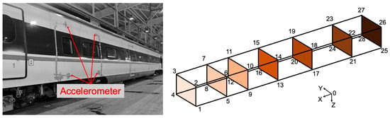
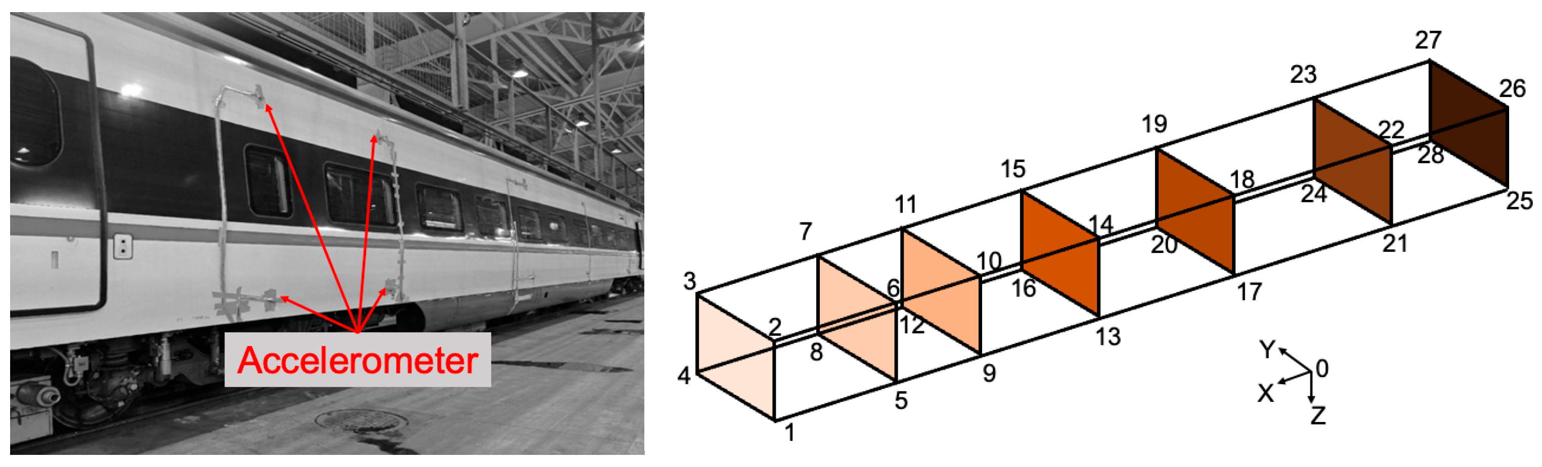
The specific type of EMU selected for testing consists of a motor car and a trailer car. The car body is welded from high-strength weathering steel, featuring a typical thin-walled cylindrical shell structure. The secondary suspension system utilizes high-flexibility air springs to achieve good vibration isolation performance. We employed 2 data acquisition systems and 56 three-axis accelerometers (piezoelectric type, sensitivity 100 mV/g, measurement range 0.5–2000 Hz) with a sampling frequency of 1024 Hz, meeting the requirements for vibration signal acquisition over a wide speed range. In this field test, the railway operator provided access to the operational EMU vehicle and the tracks, while the measurements were independently executed by our research team. The layout of the measurement points followed the principle of full coverage while deliberately avoiding the primary nodal points of the fundamental bending and torsional modes, which were predetermined via a preliminary Finite Element Analysis (FEA). Seven test sections were set up on the bodies of the motor and trailer cars; each section encompassed 4 measurement points located at the side wall beam, roof beam, and key positions of the underframe. Each measurement point synchronously collected vertical (Z-direction) and lateral (Y-direction) translational degrees of freedom (DOF), forming a total of 112 test channels. All channels achieved microsecond-level synchronization via a GPS/PTP protocol. The coordinate system is defined as longitudinal (X) along the direction of train travel, lateral (Y) horizontally perpendicular to the track, and vertical (Z) perpendicular to the ground upwards, conforming to the right-hand rule (Figure 1). To minimize uncertainties in damping ratio estimates introduced by environmental factors, all multi-condition field tests were conducted under strictly controlled similar environmental conditions: clear weather, ambient temperatures of 20 ± 5 °C, and wind speeds below 5 m/s.
Figure 1.
Arrangement of measurement points on car body (the numbers indicate the locations of the measurement points and different colors represent the cross-sections at various locations of the car body).
2.2. Multi-Condition Design
We designed four orthogonal test conditions as follows:
① Speed Sensitivity Condition
Designed to verify the stability of the vehicle’s inherent modal parameters across different operational speeds. Based on maintaining a consistent structural vehicle state, speed increments of 10~20 km/h were used to cover the full speed range of 40~200 km/h.
High-speed range (120~200 km/h): Line A (ballastless track) was selected. This line has excellent smoothness and is mainly used to evaluate aerodynamic load characteristics and vehicle modal stability under high-speed operations.
Low-speed range (40~100 km/h): Line B (ballasted track) was selected. This line has obvious subgrade settlement and joint irregularities, and is mainly used to examine the dynamic response of a vehicle under severe road excitation conditions.
② Mass Perturbation Condition
Unlike the simplified uniform Euler–Bernoulli beam models frequently employed in analytical studies, the baseline configuration of an actual EMU vehicle inherently features a complex, non-uniform mass distribution, including heavy concentrated loads from under-floor equipment (e.g., traction transformers and converters). To realistically simulate mass variations resulting from extreme passenger overload or structural retrofits upon this baseline, standard iron weights were uniformly distributed throughout the motor car. Furthermore, to ensure the fidelity of the dynamic response, all weights were rigidly fastened to the floor, thereby eliminating any secondary impact vibrations or noise interference that could arise from weight displacement during operation.
Baseline State: Axle load 17 t (including empty car and test equipment).
Increased Weight State: Axle load 19 t (increased by approximately 11.8% via counterweights). For context, the standard maximum axle load for the studied EMU is typically strictly limited to 17 t to minimize track wear. Therefore, the 19 t configuration represents an extreme, beyond-design-limit condition to rigorously evaluate mass sensitivity.
③ Suspension Fault Condition
This condition was designed to simulate the failure state of the secondary suspension system. By artificially controlling the vehicle’s pneumatic system, the compressed air in the secondary air springs was exhausted to simulate a “deflation” fault caused by air spring damage or height valve failure. In this state, the car body is directly supported on the emergency rubber stack inside the air spring.
④ Topological Connection Condition
Single-Train Mode: The vehicle operates and is tested as an independent unit.
Coupled Mode: The motor car is mechanically and electrically connected to the control car of another train via a coupler to form a coupled formation, examining the influence of longitudinal coupling on dynamic performance.
Each condition was assessed at least 3 times to ensure data reliability. Track status, ambient temperature, and other interference factors were recorded during the test to support subsequent data processing.
3. Modal Identification Methodology
First, the collected vibration acceleration signals underwent pre-processing, which included detrending, filtering (500 Hz low-pass filter), and outlier removal. Subsequently, the Stochastic Subspace Identification (SSI) method was used to identify the modal parameters of each order [28,29]. Assuming that the collected multi-channel random vibration response signal is (where (m) is the number of output channels), and the discrete time series is t = 1, 2, …, N, the response data matrix can be constructed as
By selecting the number of block rows p (usually p = 10∼20), a -dimensional Hankel matrix can be constructed. The Hankel matrix is the core of the stochastic subspace method, implicitly constructing the system state-space model by stacking response data with time delays. Singular Value Decomposition (SVD) is performed on the Hankel matrix to separate the observable subspace from the redundant subspace:
where is the diagonal matrix composed of significant singular values, and are the left and right singular vector matrices corresponding to the significant singular values, and , , and are the matrices related to the redundant subspace. The left singular vector matrix can be partitioned by block rows as follows:
The system matrix (state matrix) is therefore
contains the inherent dynamic information of the system and is the key matrix used for extracting modal parameters. Eigenvalue decomposition of allows for the identification of system modes and mode shapes. Finally, statistical analysis methods are used to compare the differences in modal parameters under different working conditions, with the significance level set to 0.05.
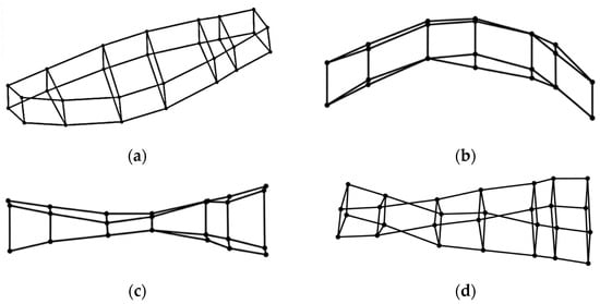
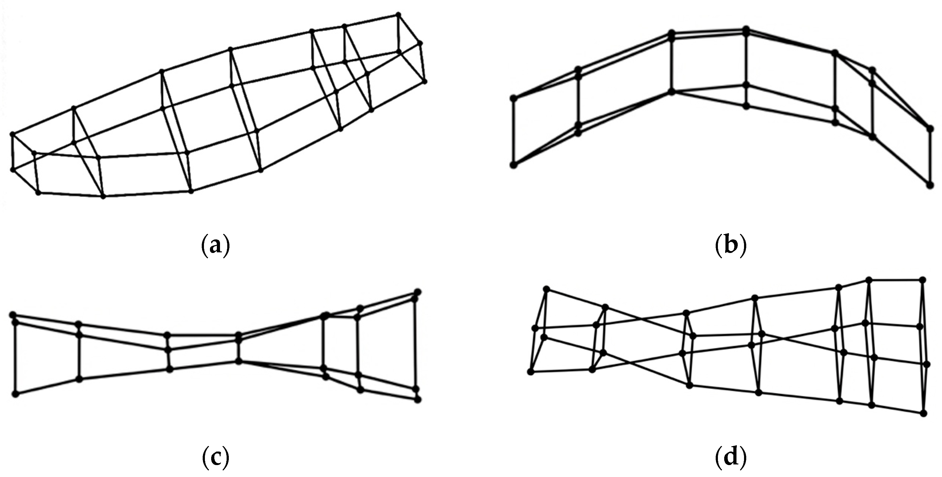
Taking the body of the trailer car as an example, using modal identification, typical key elastic shapes were obtained (Figure 2): the first-order diamond, vertical bending, breathing, and torsional modes.
Figure 2.
Diagrams of car body modal shapes. (a) First-order diamond mode; (b) first-order vertical bending mode; (c) first-order breathing mode; (d) first-order torsional mode.
4. Test Results and Parameter Influence Analysis
From the perspective of classical structural dynamics, natural vibration modes and their corresponding frequencies are intrinsic characteristics of a mechanical system. Consequently, under identical boundary conditions, changes in operational speed should theoretically not alter the natural frequencies. Our primary objective was therefore to experimentally verify the stability of modal parameters across different speeds, and to precisely quantify the magnitude of frequency shifts under mass perturbations and structural faults.
4.1. Evolution Laws of Modal Characteristics and Excitation Sensitivity in Full Speed Range
Table 1 shows the modal frequencies of the trailer car during stable high-speed operation at speeds ranging from 120 km/h to 200 km/h. The results indicate that during this 80 km/h range, the fluctuations in the modal frequencies of both the motor and trailer cars are extremely small. The standard deviation of the first-order vertical bending frequency of the motor car is only 0.014 Hz, and the coefficient of variation for the trailer car’s torsional frequency is only 0.11%. Although the aerodynamic lift and lateral force increased significantly at 200 km/h, no monotonic frequency drift was observed. This result confirms that within the current operating speed range, aerodynamic stiffness is a high-order small quantity relative to the car body’s metal structural stiffness (magnitude of 107 N/m) and does not induce non-linear hardening or softening.
Table 1.
Trailer car body modal frequencies (high-speed range).
To verify the modal characteristics under low-speed conditions, test data from Line B (ballasted track, lower subgrade stiffness, greater irregularity) was introduced. Table 2 shows the identification results for the trailer car in the low-speed range. It can be seen that at the extremely low speed of 40 km/h, although the geometric irregularity of the track is large, the high first-order breathing mode (approx. 11.5 Hz) cannot form clear poles due to the lack of sufficient excitation energy and remains in an “unidentified” state. This indicates that speed mainly affects the “observability” of the modes. For the fundamental modes identified at low speeds (e.g., diamond, vertical bending, torsional), their frequency values (e.g., 9.82 Hz for vertical bending at 40 km/h) are highly consistent with the high-speed condition at 200 km/h (9.87 Hz), with a deviation of less than 0.5%. As the speed increases from 40 km/h to 100 km/h, the wheel–rail excitation energy increases, and the breathing mode gradually becomes identifiable, with a frequency around 11.52 Hz.
Table 2.
Trailer car body modal frequencies (medium-/low-speed range).
Comprehensive test results across the full range of speed (40~200 km/h) show that operating speed does not change the inherent modal parameters of the car body structure. The absence of certain modes at low speeds is due to insufficient excitation energy, not a change in structural properties. Therefore, when performing modeling and correction for vehicle dynamics, there is no need to introduce speed-dependent stiffness correction coefficients; fundamental modal data obtained from low-speed tests can serve as a direct benchmark for high-speed operation.
4.2. Influence of Load Conditions on Operational Modes
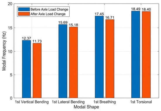
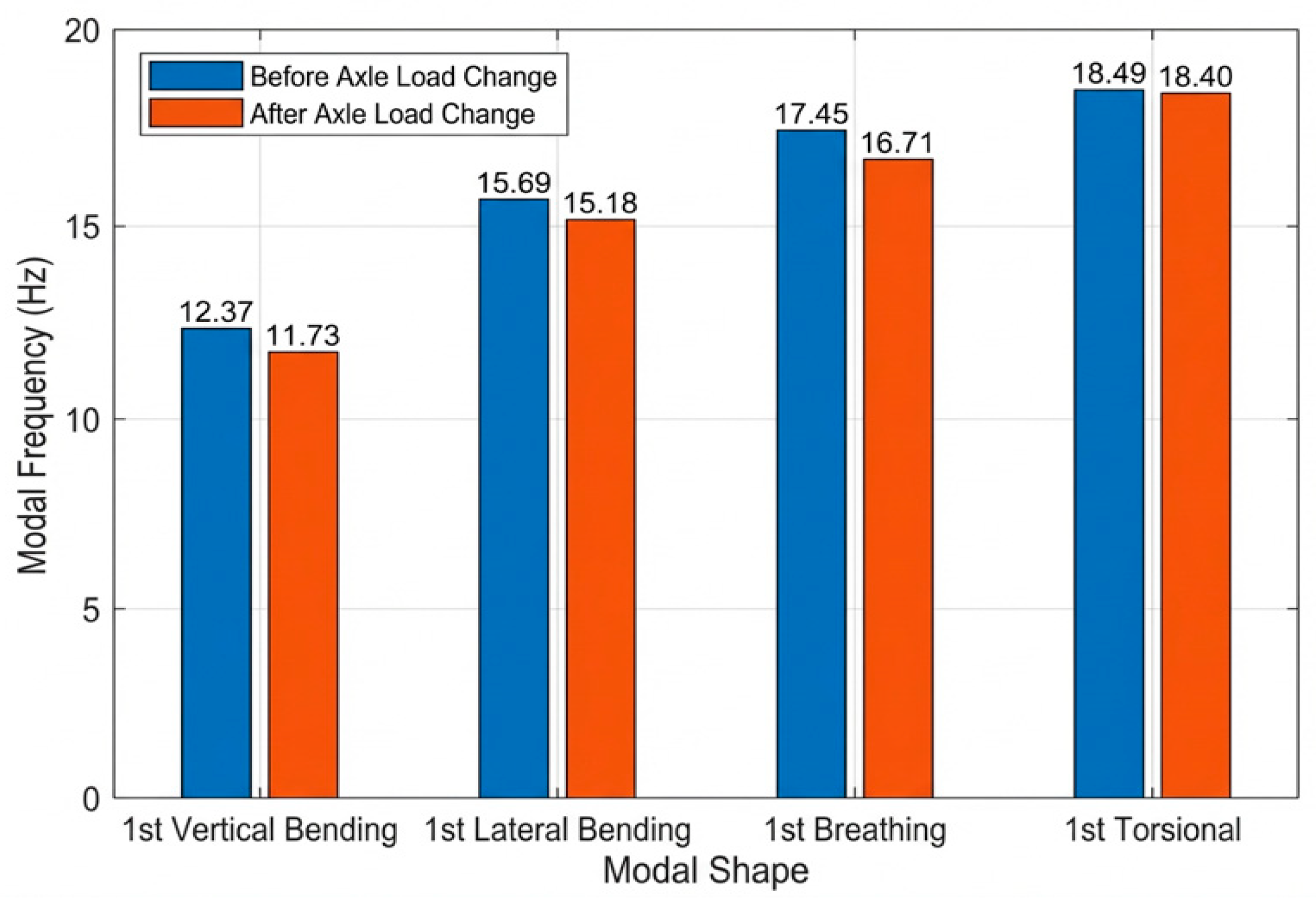
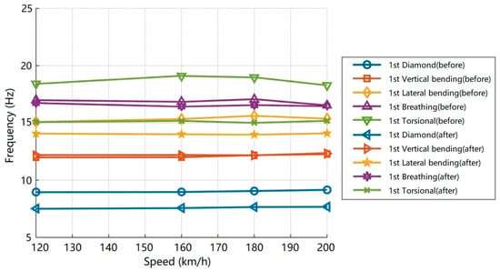
Tests were conducted on the motor car under different load conditions to analyze the effect of axle load on its operational modes. Weights were uniformly distributed inside the car and fixed and constrained, increasing the axle load from 17 to 19 tons. Figure 3 shows the comparison of modal frequencies before and after the axle load change; it can be seen that after the load increases, the frequencies of all modes show an overall downward trend. The first-order vertical bending modal frequency decreased from 12.37 Hz to 11.73 Hz, a drop of 0.64 Hz (approx. 5.17%); the first-order lateral bending modal frequency decreased from 15.69 Hz to 15.18 Hz, a drop of 0.51 Hz (approx. 3.25%); and the first-order breathing modal frequency decreased from 17.45 Hz to 16.71 Hz, a drop of 0.74 Hz (approx. 4.24%). In contrast, the first-order torsional modal frequency changed the least, only decreasing from 18.49 Hz to 18.40 Hz, a drop of 0.09 Hz (<0.5%). These results indicate that an increase in axle load has a relatively significant impact on the low-order bending-type modes (vertical bending, lateral bending, and breathing) of the vehicle, while its impact on the torsional mode is weaker. While this downward trend in natural frequencies due to increased mass aligns with fundamental dynamic principles, the significant contribution of this study lies in its precise quantification of these decreases under real-world track excitation conditions. It should be noted that due to the logistical constraints of full-scale field testing, mass perturbation was evaluated at two discrete states (17 t and 19 t). While the current data confirms a significant drop in frequency, continuous sensitivity analyses should be conducted in future to determine potential non-linear thresholds across the entire operational load range utilizing either laboratory rig tests or detailed Finite Element (FE) simulations.
Figure 3.
Comparison of motor car modal frequencies before and after axle load change.
4.3. Influence of Air Spring Deflation on Operational Modes
An air spring fault test was conducted on the trailer car to analyze the effect of deflation on operational modes. Table 3 presents the detailed modal data under the states of normal inflation and complete deflation. The results indicate a rightward frequency shift for rigid body modes: the “soft characteristic” of the suspension system disappears, causing the rigid body modal frequencies (heave and pitch) to rise significantly and approach the elastic modal frequency band. This deterioration in vibration isolation performance is the physical root cause of the “bumpiness” perceived by passengers during air spring faults.
Table 3.
Detailed comparison of modal parameters before and after trailer air spring deflation.
Regarding the car body’s elastic modes, while the diamond and vertical bending modes show marginal increases, the first-order torsional frequency exhibits a sharp rise from 13.86 Hz to 15.74 Hz, an increase exceeding 13%. This can be attributed to the fact that following deflation of the air springs, the car body rests directly on the emergency rubber stacks. The vertical stiffness of these rubber stacks far exceeds that of the air springs, and the substantial lateral span between the two stacks creates a large anti-torsion couple, significantly enhancing the car body’s rolling and torsional stiffness. It is worth noting that the breathing modal frequency decreases slightly by 2.34%. This is likely because the rigid connection alters the boundary impedance of the side wall vibration, leading to a redistribution of the effective mass participating in this mode shape. Although an increase in boundary stiffness predictably raises natural frequencies, our identification of the torsional mode as the most sensitive parameter—exhibiting an exact 13.56% surge—provides a critical, quantifiable threshold for the predictive maintenance of air spring faults. Beyond frequency shifts, this “stiff” boundary condition has profound implications for train safety and operation. The loss of the air spring’s vibration isolation leads to a significant increase in the transmission of high-frequency wheel–rail contact forces to the car body. This not only drastically degrades passenger ride comfort—potentially exceeding the limits defined by the ISO 2631 standard [30]—but also accelerates the accumulation of high-frequency stress cycles, thereby reducing the structural fatigue life of the car body.
4.4. Influence of Train Coupling on Operational Modes
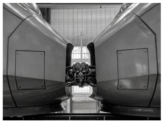
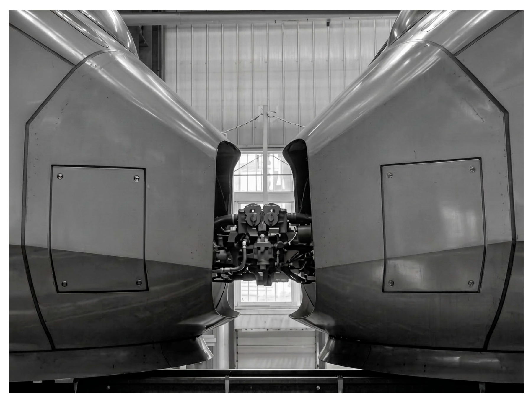
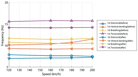
Figure 4 shows the multiple-unit connection diagram of the motor car and trailer. Figure 5 and Figure 6 show the modal frequency identification results for the motor and trailer car bodies under the condition of two coupled trains operating on the same line. It is evident that for both cars, in the 120~200 km/h speed range, the frequencies of various elastic body modes show varying decreases after coupling compared to the single-train mode. However, the trend of variation with speed remains basically unchanged. This suggests that coupled operation introduces complex longitudinal coupling and end constraints, which primarily manifest as an increase in system damping and a slight reduction in stiffness frequencies. Specifically, the mechanical coupler and inter-car dampers act as significant longitudinal stiffness and damping elements, which couple the pitch and longitudinal modes of the adjacent cars. This interaction restricts the free boundary conditions at the vehicle ends, primarily manifesting as an increase in global system damping and a slight reduction in the natural frequencies of the fundamental elastic modes compared to the single-unit configuration.
Figure 4.
Coupled operation conditions.
Figure 5.
Comparison of motor car modal frequencies before and after coupling of motor and trailer cars.
Figure 6.
Comparison of trailer car modal frequencies before and after coupling of motor and trailer cars.
5. Conclusions
Following systematic experiments, we performed in-depth analyses to determine the influences of operating speed, axle load, air spring status, and coupling conditions on the operational modes of a certain type of EMU. Our conclusions are as follows:
Operating speed has a weak perturbation effect on the modal characteristics of car bodies. In the 120~200 km/h speed range, the amplitude of variation in modal frequencies for motor and trailer cars is small. Operating speed may only affect the order of modes that can be effectively excited (observability) and does not change the inherent modal parameters determined by structural stiffness, mass distribution, and boundary conditions.
Increased axle load significantly affects low-order bending modes. Increasing the axle load from 17 to 19 tons caused a downward trend in the frequencies of the first-order vertical bending, lateral bending, and breathing modes, with decreases of 5.17%, 3.25%, and 4.24%, respectively. Conversely, the impact on the torsional mode was minimal (a decrease of <0.5%).
Air spring deflation alters car body support boundary conditions. After deflation, the emergency rubber spring replaces the air spring for support, leading to increased suspension stiffness. Rigid body modal (heave, pitch) frequencies rise significantly, and the torsional modal frequency increases markedly (+13.6%). This law provides a key basis for air spring fault diagnosis.
Train coupling also affects car body elastic mode characteristics. Under coupled conditions, the frequencies of various elastic body modes for both motor and trailer cars decrease to varying degrees compared to independent operation.
In conclusion, this study elucidates the primary influencing factors and dynamic evolution mechanisms of railway vehicle operational modes under complex, coupled operating conditions. The empirical data and analytical insights derived from this research offer robust technical support for structural optimization, modal matching control, and the development of intelligent fault diagnostic systems for rail transit equipment, demonstrating substantial practical value for improving the safety and passenger comfort of high-speed railway vehicles. Drawing on these findings, we propose the following actionable recommendations for industry practitioners:
For railway carriers, integrating real-time monitoring of car body modal characteristics into an on-board structural health monitoring (SHM) system is highly advisable. Specifically, configuring SHM algorithms to continuously track key parameters—such as abrupt variations in torsional frequency—can provide a highly reliable signature for severe suspension failures (e.g., air spring deflation), thereby enabling real-time detection and triggering automated safety warning protocols.
For infrastructure managers, considering that increased axle loads during peak passenger periods can diminish a vehicle’s low-order bending frequencies by up to 5%, proactive track maintenance should be scheduled to mitigate specific track irregularity wavelengths that could otherwise induce resonance with these shifted modes.
Author Contributions
Conceptualization, Z.X.; Methodology, Z.X.; Validation, D.G.; Investigation, D.G.; Resources, B.L.; Data curation, B.L.; Writing—original draft, Z.X.; Writing—review & editing, D.G. All authors have read and agreed to the published version of the manuscript.
Funding
The authors acknowledge the financial support provided by the Science and Technology Research and Development Program of China National Railway Group Co., Ltd. (Grant No. Q2025J022).
Data Availability Statement
The data presented in this study are available on request from the corresponding author.
Conflicts of Interest
Authors Zhanghui Xia and Baochen Liu were employed by the company China Academy of Railway Sciences Corporation Limited. The remaining authors declare that the research was conducted in the absence of any commercial or financial relationships that could be construed as a potential conflict of interest.
References
- Iida, K.; Sakai, K.; Miyamoto, T. Dynamic simulations of railway vehicles running on tracks with lateral and roll vibrations including rail tilting. In Dynamics of Vehicles on Roads and Tracks: Vol 2; CRC Press: Boca Raton, FL, USA, 2018; pp. 1303–1308. [Google Scholar]
- Gong, D.; Liu, G.Y.; Zhou, J.S. Research on mechanism and control methods of carbody chattering of an electric multiple-unit train. Multibody Syst. Dyn. 2021, 53, 135–172. [Google Scholar] [CrossRef] [Scilit]
- Torun, Y.E.; Erol, H. A trade-off study among ride comfort and safety against derailment in the rail vehicle suspension design. J. Vib. Eng. Technol. 2025, 13, 393. [Google Scholar] [CrossRef] [Scilit]
- Barbosa, R.S.; Santos, G.F.M. Experimental investigation on the dynamic behaviour of a railway vehicle travelling through a turnout. Int. J. Heavy Veh. Syst. 2009, 16, 189–206. [Google Scholar] [CrossRef] [Scilit]
- Wang, Z.G.; Gong, D. A survey on countermeasures of railway vehicle stability decrease caused by the evolution of hollow-worn wheels. J. Vib. Control. 2025, 31, 864–877. [Google Scholar] [CrossRef] [Scilit]
- Zhao, C.; Fan, Z.; Li, P.; Gebreyohanes, M.Y.; Wang, Z.; Mo, J. Research on the dynamic response characteristics of a railway vehicle under curved braking conditions. Vehicles 2025, 7, 18. [Google Scholar] [CrossRef] [Scilit]
- Han, Y.; Crosbee, D.; Wang, R.; Allen, P.; Feng, W. Propagation trends of cracks situated in bogie frames based on a rigid-flexible coupled vehicle dynamic model. Veh. Syst. Dyn. 2024; advance online publication. [CrossRef] [Scilit]
- Dumitriu, M.; Apostol, I.I.; Stanica, D.I. Influence of the suspension model in the simulation of the vertical vibration behavior of the railway vehicle car body. Vibration 2023, 6, 512–535. [Google Scholar] [CrossRef] [Scilit]
- Zhou, J.; Goodall, R.; Ren, L.; Zhang, H. Influences of car body vertical flexibility on ride quality of passenger railway vehicles. Proc. Inst. Mech. Eng. Part F J. Rail Rapid Transit 2009, 223, 461–471. [Google Scholar] [CrossRef] [Scilit]
- Dumitriu, M. On-line running tests for validating the numerical simulations of the vertical dynamic behavior in railway vehicles. In Engineering Solutions and Technologies in Manufacturing (Applied Mechanics and Materials); Trans Tech Publications Ltd.: Baech, Switzerland, 2014; Volume 657, pp. 609–613. [Google Scholar] [CrossRef] [Scilit]
- Mazilu, T.; Dumitriu, M.; Sorohan, S.; Gheți, M.A.; Apostol, I.I. Testing the effectiveness of the anti-bending bar system to reduce the vertical bending vibrations of the railway vehicle carbody using an experimental scale demonstrator. Appl. Sci. 2024, 14, 4687. [Google Scholar] [CrossRef] [Scilit]
- Fang, J.; Li, X.; Zhang, D.; Zhang, X.; Shao, W. Research on load reverse engineering and vibration fatigue analysis technology of rapid box wagon. Materials 2022, 15, 8322. [Google Scholar] [CrossRef] [Scilit]
- Wang, W.Q.; Ren, Z.S.; Ma, J.F.; Zhu, S.G. Determination of wheel eccentric wear limit under high-speed operation based on bogie frame fatigue life. Eng. Fail. Anal. 2026, 184, 110309. [Google Scholar] [CrossRef] [Scilit]
- Sharma, S.K.; Sharma, R.C.; Lee, J. Effect of rail vehicle-track coupled dynamics on fatigue failure of coil spring in a suspension system. Appl. Sci. 2021, 11, 2650. [Google Scholar] [CrossRef] [Scilit]
- Kumar, R.; Sharma, T.; Shekhar, A.; Vyas, N.S. Primary suspension failure analysis in FIAT type LHB bogies and life estimation. Eng. Fail. Anal. 2022, 138, 106320. [Google Scholar] [CrossRef] [Scilit]
- Men, Z.; Gong, D.; Zhou, K.; Chen, Y.; Zhou, J. Unsupervised domain adaptation method for bearing fault diagnosis assisted by twin data under extreme sample scarcity. Mech. Syst. Signal Process. 2025, 239, 113359. [Google Scholar] [CrossRef] [Scilit]
- Cascino, A.; Meli, E.; Rindi, A. High-fidelity finite element modelling (FEM) and dynamic analysis of a hybrid aluminium-honeycomb railway vehicle carbody. Appl. Sci. 2026, 16, 549. [Google Scholar] [CrossRef] [Scilit]
- Melero, M.; Nieto, A.J.; Casero-Alonso, V.; Palomares, E.; Morales, A.L.; Ramiro, C.; Chicharro, J.M.; Pintado, P. Design of experiments to determine the influence of test procedure on experimental modal analysis. J. Sound Vib. 2022, 538, 117229. [Google Scholar] [CrossRef] [Scilit]
- Martinod, R.M.; Betancur, G.R.; Heredia, L.F.C. Identification of the technical state of suspension elements in railway systems. Veh. Syst. Dyn. 2012, 50, 1121–1135. [Google Scholar] [CrossRef] [Scilit]
- Gong, D.; Wu, J.W.; Lan, J.Y.; Zhou, K.; Zhou, J.S. Research on abnormal flexible vibrations of intercity rail vehicle car bodies and its control based on modal force decomposition. Proc. Inst. Mech. Eng. Part F J. Rail Rapid Transit, 2025; advance online publication. [CrossRef] [Scilit]
- Calvo, L.E.; Castellanos, G.A.; Gimenez, G. Analysis of instabilities in railway vehicles employing operational modal analysis. In Proceedings of the ASME Joint Rail Conference; V001T10A005; ASME: New York, NY, USA, 2015. [Google Scholar]
- Cascino, A.; Nencioni, L.; Lanzillo, L.; Mazzeo, F.; Strano, S.; Terzo, M.; Delle Monache, S.; Meli, E. Development and Experimental Validation of a Physics-Based Digital Twin for Railway Freight Wagon Monitoring. Sensors 2026, 26, 643. [Google Scholar] [CrossRef] [Scilit]
- Tang, J.; Zhou, Z.; Chen, H.; Wang, S.; Gutiérrez, A. Research on the lightweight design of GFRP fabric pultrusion panels for railway vehicle. Compos. Struct. 2022, 286, 115221. [Google Scholar] [CrossRef] [Scilit]
- Tang, J.; Zhou, Z.; Chen, H.; Wang, S.; Gutiérrez, A.; Zhang, C.; Deng, J. Laminate design, optimization, and testing of an innovative carbon fiber-reinforced composite sandwich panel for high-speed train. Polym. Compos. 2021, 42, 5811–5829. [Google Scholar] [CrossRef] [Scilit]
- Luo, R.K.; Gabbitas, B.L.; Brickle, B.V. Fatigue Life Evaluation of a Railway Vehicle Bogie Using an Integrated Dynamic Simulation. Proc. Inst. Mech. Eng. Part F J. Rail Rapid Transit 1994, 208, 123–132. [Google Scholar] [CrossRef] [Scilit]
- Luo, R.K.; Gabbitas, B.L.; Brickle, B.V. Dynamic stress analysis of an open-shaped railway bogie frame. Eng. Fail. Anal. 1996, 3, 53–64. [Google Scholar] [CrossRef] [Scilit]
- Cascino, A.; Meli, E.; Rindi, A. Design and Optimization of a Hybrid Railcar Structure with Multilayer Composite Panels. Materials 2025, 18, 5013. [Google Scholar] [CrossRef] [Scilit]
- Wagner, G.; Lima, R.; Sampaio, R. Modal identification of a light and flexible wind turbine blade under wind excitation. J. Eng. Math. 2022, 133, 3. [Google Scholar] [CrossRef] [Scilit]
- O’Connell, B.J.; Rogers, T.J. A robust probabilistic approach to stochastic subspace identification. J. Sound Vib. 2024, 581, 118381. [Google Scholar] [CrossRef] [Scilit]
- ISO 2631-1:2010; Mechanical Vibration and Shock—Evaluation of Human Exposure to Whole-Body Vibration—Part 1: General Requirements. International Organization for Standardization: Geneva, Switzerland, 2010.

Disclaimer/Publisher’s Note: The statements, opinions and data contained in all publications are solely those of the individual author(s) and contributor(s) and not of MDPI and/or the editor(s). MDPI and/or the editor(s) disclaim responsibility for any injury to people or property resulting from any ideas, methods, instructions or products referred to in the content. |
© 2026 by the authors. Licensee MDPI, Basel, Switzerland. This article is an open access article distributed under the terms and conditions of the Creative Commons Attribution (CC BY) license.