


Abstract
Many industrial machines inevitably suffer from external impacts which can change the meshing state of gears and thus affect the vibration characteristics of the gear transmission system. Previous studies mostly directly applied external impact excitation to the gear pair, with few considering the gear–shaft-bearing system. In reality, external impact excitation first acts on the bearing ends and then is transmitted to the gear ends through the transmission shaft. Therefore, the paper established a bending–torsion coupled dynamic model of the gear–shaft-bearing transmission system, taking into account external impacts, gear eccentricity, time-varying meshing stiffness, transmission error, shafts elastic deformation and nonlinear reactions forces. The vibration characteristics of the bending–torsion coupled gear–shaft-bearing transmission system under external impacts were analyzed in the time and frequency domains. Additionally, the effects of impact load amplitude and impact duration on gear vibration characteristics were investigated. External impacts instantaneously amplified the vibrational energy of the gear pair, which promotes the generation of impact components and increases the vibration acceleration signal amplitude in the time domain. Distinct sidebands emerge in the frequency domain, with meshing impacts intensified during gear operation. Furthermore, as the impact load amplitude increases and the impact duration is shortened, the vibration characteristics of the gear transmission system become more pronounced. The findings provide important theoretical insights and practical engineering significance for improving the reliability and service life of gear transmission systems.
1. Introduction
1.1. Research Background
As a critical component of mechanical systems, gear mechanisms are widely employed in industrial fields (e.g., mechanical manufacturing, energy and power, and aerospace) due to their stable transmission ratio, compact structure, and high transmission efficiency. The vibration characteristics of gear transmission systems directly affect the operational performance and efficiency of the entire equipment while inducing noise pollution in the environment. Requirements for vibration performance of gear transmission systems have become increasingly stringent with the increasing demand for mechanical equipment with higher reliability, longer service life, and greater precision. Therefore, the vibration response characteristics of gear transmission systems are studied to reduce vibrations and noises as well as improve transmission, service life, and the reliability of gear transmission systems.
1.2. Literature Review
In the domain of gear–rotor-bearing coupling dynamics modeling, a significant body of research has been conducted by numerous scholars. Qiao et al. [1] developed a finite element model of a two-stage spur gear transmission system, taking into account factors such as time-varying meshing stiffness, time-varying bearing stiffness, transmission error, and shaft flexibility. The researchers analyzed the influence of transmission shaft stiffness on the vibration modes and dynamic response of the gear system. Xu et al. [2] developed a nonlinear gear–shaft-bearing–housing dynamics model to investigate the effects of gear meshing forces and radial bearing clearance variations on system vibration responses. In addition, they proposed a method for evaluating radial bearing clearance through vibration data. This method utilizes a modulated signal double-spectrum sideband evaluation. Establishing an accurate bearing dynamic model is an important step in understanding the vibration characteristics of gear–rotor-bearing systems. Tu et al. [3,4] considered the dynamic contact relationship among rollers, raceways and cages, and established a nonlinear dynamic model of cylindrical roller bearings. They respectively discussed the changes in the motion characteristics of the cage and their intrinsic mechanisms under uniform speed, acceleration, deceleration and harmonic speed fluctuations, and simultaneously analyzed the influences of angular acceleration, angular deceleration, amplitude and fluctuation period on the stability of the cage. Zeng et al. [5] developed a gear–rotor-bearing coupled system, taking into account factors such as interference fit between the bearing inner ring and shaft, clearance fit between the bearing outer ring and housing, periodic gear meshing stiffness excitation, and random collisions between the bearing cage and the rolling elements. The investigation focused on the impact of clearance variations between bearing rings and shaft/housing on system vibration response. Liu et al. [6] developed a dynamic model of the gear-bearing system and investigated the effect of time-varying roller bearing stiffness on the vibration characteristics of the GRB system. Wang et al. [7] developed a dynamic model for the gear–shaft-bearing coupled system, taking into account rotor eccentricity. The model was utilized to analyze the effects of rotor eccentricity, input speed, and external loads on the system’s vibration characteristics. Dai et al. [8] developed a gear–shaft-bearing dynamics model that incorporates gear pair spalling defects and localized defects in both the inner and outer bearing raceways. The investigation encompassed the analysis of alterations in the vibration characteristics of the defective gear transmission system under diverse operating conditions, encompassing variations in speed, load, and speed fluctuations. Mo et al. [9] constructed a nonlinear dynamic model of the gear–rotor-bearing coupled transmission system in new energy vehicles, accounting for time-varying meshing stiffness, time-varying support stiffness, transmission error, flank clearance, and bearing clearance. The investigation focused on the impact of external load excitation frequency on the system’s vibration characteristics. Ouyang et al. [10] developed a dynamic model for a helical gear–roller-bearing system that incorporates time-varying characteristics and contact nonlinearity. The investigation encompassed the vibration characteristics of the gear–shaft-bearing system under varying operating conditions, concurrently developing a novel apparatus for experimental measurement. Gao and Gao. [11] developed a nonlinear dynamic model for a 39-degree-of-freedom sliding bearing-secondary helical gear planetary system, accounting for nonlinear oil film forces, time-varying meshing stiffness, and flank clearance. The investigation encompassed the examination of the effects of rotational speed, nonlinear oil film forces, and bearing clearance on system dynamics. Ullah et al. [12] initially implemented the finite element method to establish a 12-degree-of-freedom dynamic model of a solitary helical gear transmission system, encompassing bearings and shafts. This model was then utilized to analyze the system’s vibration characteristics at varying rotational speeds. Wang et al. [13] developed a finite element model of a three-gear rotor system to investigate changes in gear vibration response under unbalanced excitation and torque load excitation. Lu et al. [14] established a dynamic model of a dual-rotor-bearing system with looseness-rubbing composite faults by the finite element method, introduced the Component Mode Synthesis (CMS) and Proper Orthogonal Decomposition (POD) methods to perform order reduction on the original rotor system model, and investigated the spectral and amplitude–frequency characteristics of the rotor system. Zhang et al. [15] established a dynamic model of a multi-degree-of-freedom helical gear–rotor-bearing transmission system with composite faults by the lumped parameter method, on the premise of considering the time-varying meshing stiffness of helical gears with crack faults, gear eccentricity faults, and the nonlinear reaction forces of faulty bearings. They analyzed the vibration response characteristics of the system under healthy conditions, single gear eccentricity fault, single-tooth root crack fault, and the coupling of bearing composite faults. Liu et al. [16] proposed a non-intrusive stiffness model for ball bearings based on the quasi-static model combined with the Chebyshev interval analysis method, which incorporates a bearing–shaft interference fit model with uncertain parameters. They investigated the influence laws of the mean value and deviation coefficient of interference fit on the coupling relationships among bearing time-varying stiffness, preload and rotational speed under different preload mechanisms. Fu et al. [17] considered key uncertain factors such as geometric deviations, material properties and assembly tolerances, and for the first time, conducted a comprehensive analysis on the dynamic characteristics and uncertainty propagation mechanisms of the pulse detonation engine rotor system. They developed a non-intrusive hybrid surrogate model, namely the Polynomial Chaos-Kriging model. Meanwhile, they analyzed the modal responses, transient responses during the start-up phase and steady-state characteristics during the constant-speed operation phase of the system, and identified the influence laws of various structural parameters on different response modes through global sensitivity analysis. Zhang et al. [18] considered the tooth impact effect of disengaged clutches, established a dynamic model of the multi-stage planetary gear-bearing–rotor-clutch coupling system applicable to multi-shift and multi-speed transmission, and revealed the influence laws of rotational speed and clutch tooth backlash on the random tooth impact characteristics of clutches. In addition, an embedded measurement method was developed to measure the in situ torsional vibration responses of rotating components under different shift and rotational speed conditions. The prevailing focus of contemporary analyses of vibration characteristics in gear-bearing coupled systems is on steady-state conditions, time-varying loads, and rotational speed scenarios. There is, however, limited research addressing impact load conditions.
In the aspect of gear pair system dynamic, Shi et al. [19] examined the impact of various factors on the vibration characteristics of gear systems. These factors included meshing stiffness, friction force, load distribution, and transmission error, as measured using the established gear dynamics model. Zhang et al. [20] proposed the contact stiffness of rough surfaces considering the actual contact state rather than using empirical assumption functions. Then, by integrating the meshing stiffness related to the mating tooth surface topography and force, an improved dynamic model of the gear pair system was established. The nonlinear dynamic characteristics of the gear system under different processing accuracies and surface topographies were revealed. Shi et al. [21] developed a six-degree-of-freedom dynamic model for a spur gears pair. This model was developed with consideration for time-varying meshing stiffness, static transmission error, time-varying flank clearance, and random load effects. The objective of this development was to analyze the impact of random loads on gear system vibration response. Zhang et al. [22] proposed an improved stiffness excitation modeling method for friction plate teeth with edge cracks. Based on this, a dynamic impact model of the floating support friction plate–inner hub system was established, which considered the influence of bending–torsion–axial-tilting coupled motion on tooth meshing excitation and dynamic response. The influence laws of crack propagation depth and the number of cracked teeth on the random impact characteristics and vibration response of the system were investigated. Cao et al. [23] developed a spur gear pair dynamics model that incorporates the force-dependent variations in gear meshing stiffness, flank clearance, and profile deviation. This model provides a comprehensive analysis of the effects of tooth surface errors and eccentricity errors on gear vibration characteristics. Dou and Liu [24] conducted a study on the local contact characteristics of gears to establish a train–track coupled dynamics model. They investigated the impact of shock forces caused by wheel defects on gear vibration characteristics. Yuan et al. [25] addressed the issue of bending–torsion–axial coupled vibrations in helical gear transmission systems. Utilizing the lumped parameter method, they developed a 10-degree-of-freedom model for high-speed train gear transmission systems incorporating motors and loads. The present model investigated the effects of internal and external excitation parameters on the vibration characteristics of high-speed train gear transmission systems. These parameters include gear rotational speed, wheel–rail creep force, support stiffness, and support damping. Chen et al. [26] incorporated both time-varying mesh stiffness and nonlinear wheel–rail contact excitation. A coupled dynamics model integrating motor–gear–wheel–rail–locomotive systems is established to analyze the vibration characteristics of gear systems under traction and braking conditions. Jiang et al. [27] established a metro helical gear model considering track spectrum excitation, time-varying meshing stiffness, transmission error, and backlash, and studied the vibration characteristics of the gear system under track spectrum excitation. Chen et al. [28] obtained the external excitation of the wind turbine gear transmission system by establishing a random fluctuation model, and constructed a dynamic model of the gear system that takes into account random wind force, time-varying meshing stiffness of gears, transmission error, and backlash, and they analyzed the impact of random wind force on the vibration characteristics of the gear system. Zhao et al. [29] developed a gear dynamics model for herringbone gears that accounts for time-varying meshing stiffness and transmission errors. Utilizing the principles of blade element momentum theory, they conducted meticulous calculations of hub loads in wind turbines. The present study investigated the impact of external excitation from turbulent wind conditions on the system’s vibration characteristics. Tong et al. [30] considering time-varying meshing stiffness, transmission error, and backlash, established a dynamic model of a spur gear system subjected to hull heave–pitch coupling, and analyzed the vibration response of the gear system caused by the additional excitation from the hull’s heave–pitch motion. The transmission systems of automobiles typically operate under highly transient working conditions. To achieve vehicle lightweighting, Milojević et al. [31] conducted research on the frictional characteristics of aluminum alloys for application in the structural design of reciprocating machinery, confirming that the application of this material can effectively reduce frictional losses. Although some of the above-mentioned studies took impact excitation into account, it was directly applied to the gears rather than transmitted to the gear meshing through the bearings.
1.3. Existing Problems
Current research on the vibration characteristics of gear–shaft-bearing transmission systems has primarily focused on steady-state conditions, variable-speed conditions, and variable-torque conditions. However, there are relatively fewer studies on vibration behavior under external impacts. External impacts are commonly encountered during gear–shaft-bearing transmission systems service due to operational environments and working conditions, characterized by extremely high force and extremely short durations, such as vehicles passing speed bumps or potholes; the transmission gears are instantaneously loaded up to three times the steady state, and the wheel flattening scars of a high-speed train can increase the wheel–rail impact by 40% instantaneously. Furthermore, in previous studies on the vibration characteristics of gears under external impact conditions, external impact excitations are generally applied directly to the gear pair system. Therefore, the established dynamic models are mostly single gear pair systems, with little consideration of the bending–torsion coupled gear–shaft-bearing transmission system. However, in practice, the impact first acts on the bearing ends and then is transmitted to the gear ends through the transmission shaft.
1.4. Research Content
Triangular pulse excitation was employed to simulate external impacts on gear transmission systems in this work. Based on the lumped parameter method, a 14-DOF bending–torsion coupled gear–shaft-bearing transmission system dynamic model was established, incorporating external impacts, gear eccentricity, time-varying mesh stiffness, transmission errors, shaft elastic deformation, and the nonlinear bearing reaction forces. The dynamic equations were numerically solved to obtain the vibration response of the gear transmission system. Variations in gear vibration characteristics were revealed under different impacts and influencing factors through time–frequency analysis of the system.
2. Establishment of the External Impact Model
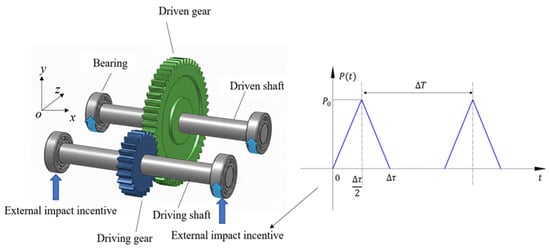
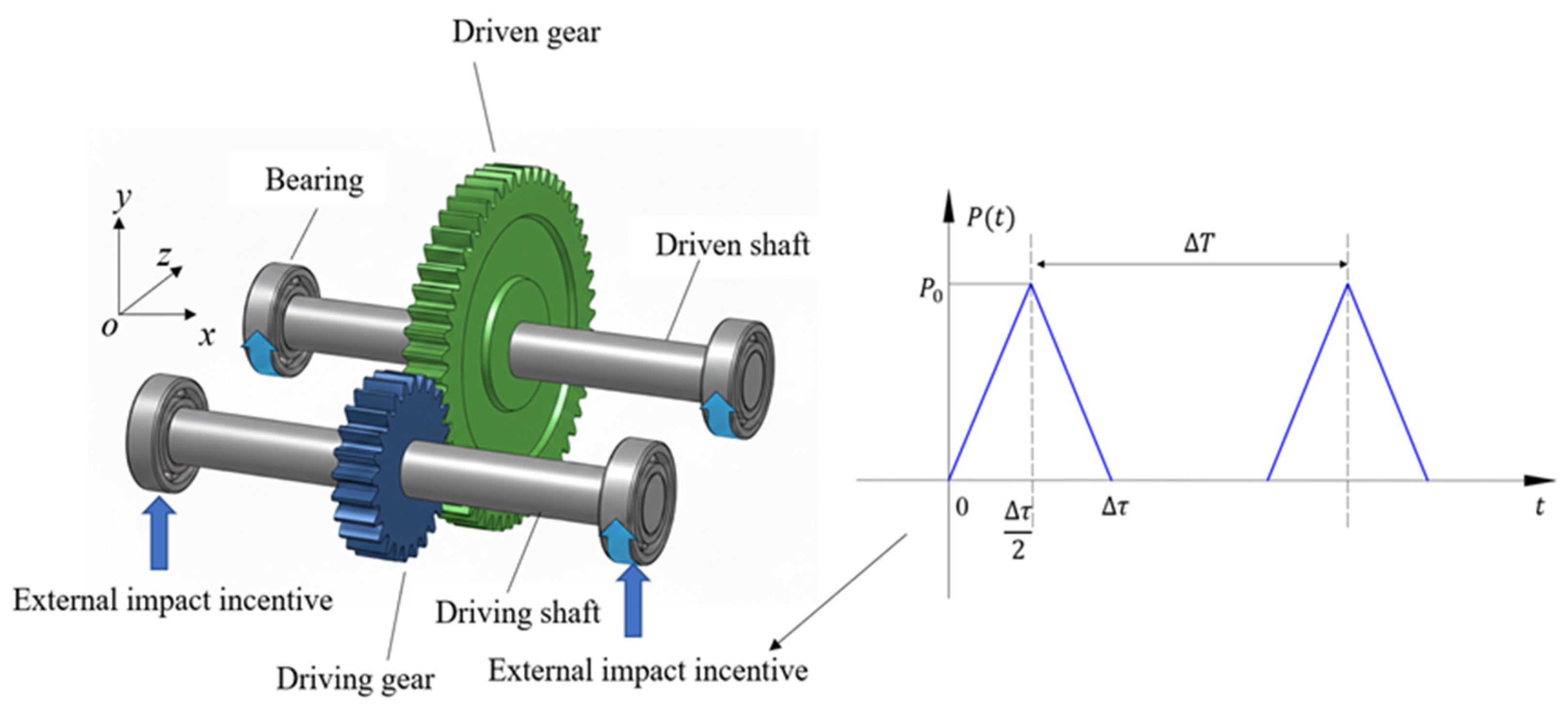
Gear transmission systems frequently experience external excitations during actual operation due to complex working environments, such as vehicles passing speed bumps or potholes and wheel flats in high-speed trains. Typically, impacts first act on bearing ends, with the resulting vibration signals transmitted to gears through shafts. Impact loads are characterized by extremely high magnitudes and short durations, representing typical pulse-type excitations. Following refs. [32,33], periodic triangular wave pulses are employed to simulate impact excitation (Figure 1). is the amplitude of triangular pulse impact load; is the impact interval time; is the impact duration (Equation (1)) [34].
where n = 0, 1, 2, … represent the nth pulse.
Figure 1.
Gear transmission system under external impacts.
As shown in Figure 1, external impacts are introduced into the system through the bearing ends. In the modeling and simulation process, since radial shock is the primary source of the system’s vibration response under most operating conditions, this study assumes that the impact force acts mainly along the radial plane (y-axis) of the bearing.
3. Establishment of the Gear Transmission System Dynamic Model
The gear transmission system typically consists of a driving gear, a driven gear, support bearings, and driving and driven shafts. Given the extreme complexity of actual gear transmission operation, appropriate model simplification facilitates more efficient analysis of vibration characteristics. Therefore, the following assumptions are made before establishing the dynamic model.
- 1.
- The flexibility of the gear teeth and support bearings, as well as the driving and driven shafts, is taken into account, and they are modeled as linear elastic bodies.
- 2.
- Gears are subject to continuous torsional vibration about their axes and translational vibration in surfaces perpendicular to the axes, with no vibration occurring along the axial direction.
- 3.
- The gear tooth meshing interaction is simplified as a spring–damper system acting at the meshing point, with the meshing direction always aligned with the line of action. The support bearings are modeled as springs and dampers in the radial direction, while both driving and driven shafts possess bending stiffness, torsional stiffness, and damping. All damping in the system is considered to be viscous.
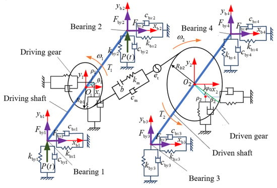
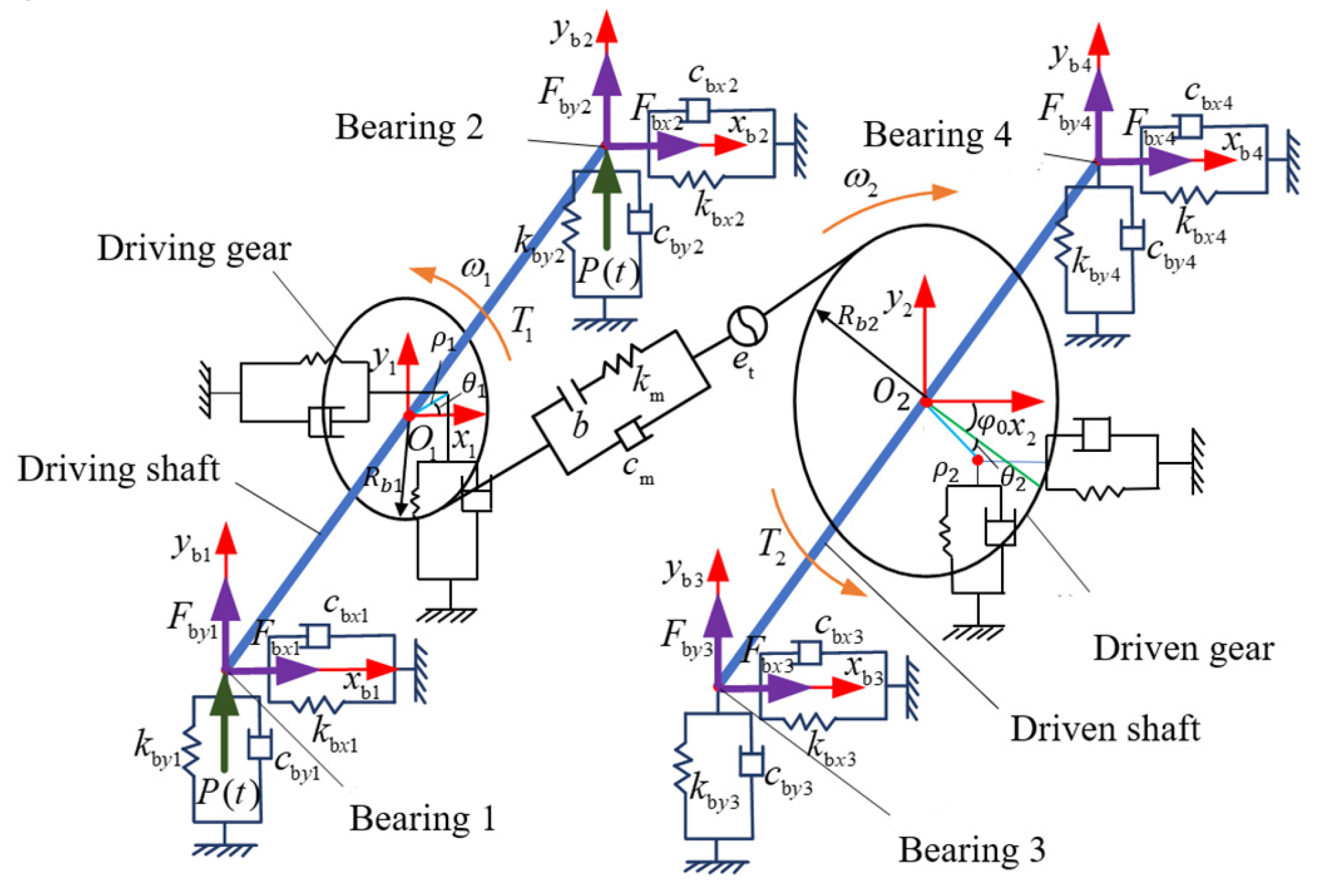
Based on these assumptions and the lumped parameter method, a 14-DOF bending–torsion coupled dynamic model of the gear–shaft-bearing transmission system is developed. This model comprehensively considers external impacts, gear eccentricity, time-varying mesh stiffness, transmission errors, nonlinear bearing force, and shaft elastic deformations. External impacts are assumed to act along the y-axis at bearings 1–2 supporting both ends of the driving shaft as shown in Figure 2.
Figure 2.
Dynamic model of a gear drive system subjected to external impact.
The local coordinate system Oixiyi is established at the driving (i = 1) and driven gears (i = 2), respectively. Oi represents the theoretical rotation center of each gear; the -axis lies along the line connecting both gears’ theoretical centers; the -axis is perpendicular to the line connecting both gears’ theoretical centers.
and are the equivalent mass and inertia moment for the driving and driven gears, respectively; is the equivalent mass for the individual support bearings; b are the backlash;
and are the time-varying mesh stiffness and mesh damping between the gear pair, respectively; is the base circle radius for the driving and driven gears; and are the support reaction forces in the x- and y- directions at each bearing location of each shaft, caused by the bending deformation of the gear shafts; and are the angular velocities of the driving and driven gears, respectively; and are the input and output load torques, respectively.
Ignoring the axial endplay of the gears, and are the coordinates of the rotation centers of the driving and driven gears, respectively. ( and ( are the corresponding centroid coordinates; and are the mass eccentricity distances. The line connecting the rotation center of the driving gear and its centroid is parallel to the coordinate axis at the initial moment. The line connecting the rotation center of the driven gear and its centroid forms angle with the coordinate axis in the direction of rotation. When and are the torsional angles of the driving and driven gears, respectively, the relationship between the centroid and the rotation center of the gears is defined by
() is assumed to be the displacement coordinates of the bearing rotation centers. and are the elastic deformations of the driving shaft in the x- and y-axes, respectively; and are those of the driven shaft, respectively. The deformation compatibility conditions of the shafts can be expressed by
where = = and represent the lengths of the driving and driven shafts between the two bearings, respectively; represents the distance from the gear rotation center to the corresponding bearing center on the driving or driven shaft.
Based on the force equilibrium conditions in the x-axis of the driving and driven shafts,
where and represent the bending stiffness of the driving and driven shafts, respectively; and represent the bending damping of the driving and driven shafts, respectively. The expressions for are identical in form to . It requires replacing with .
3.1. Calculation of Time-Varying Mesh Stiffness
Mesh stiffness is a dynamic excitation caused by the time-varying characteristics of the comprehensive mesh stiffness during gear engagement. The potential energy method is employed to obtain gear mesh stiffness in the work. Since gear engagement alternates between single-tooth contact and double-tooth contact, the comprehensive mesh stiffness of the gear pair shall be calculated separately for these two scenarios.
For the single-tooth engagement zone [35,36],
For the double-tooth engagement zone [35,36],
where j = 1 represents the driving gear; j = 2 represents the driven gear, i = 1 represents the meshing of the first pair of gear teeth; i = 2 represents the meshing of the second pair of gear teeth.
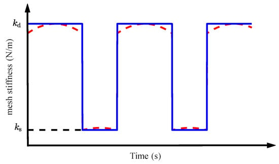
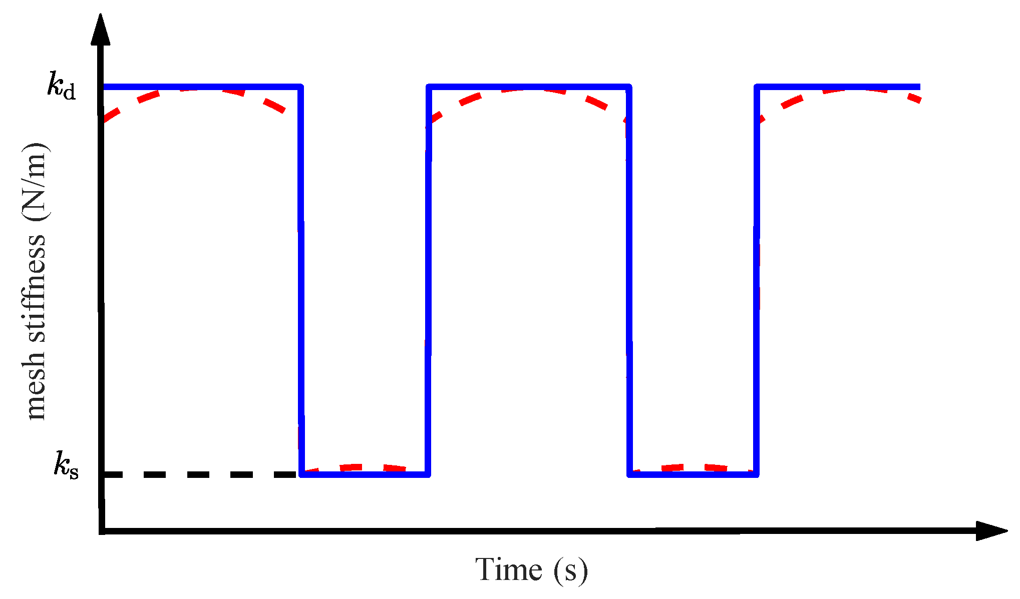
Comprehensive mesh stiffness during gear engagement exhibits periodic variations with abrupt changes due to the non-integer contact ratio in spur gears. A rectangular wave is adopted to represent time-varying mesh stiffness for calculation (Figure 3) [37]. and represent the maximum and minimum mesh stiffness, corresponding to stiffness in the double- and single-tooth engagement zones, respectively.
Figure 3.
Time-varying mesh stiffness.
3.2. System Differential Equations
The dynamic transmission error induced by dynamic excitation is defined by
where transmission error is caused by the gear manufacturing and installation errors, serving as one of the primary dynamic excitations during gear meshing (Equation (8)) [38].
where represents the amplitude of the transmission error; represents the meshing angular frequency ().
The dynamic meshing force acting on the gear teeth is expressed as follows [39].
where are the displacement-dependent nonlinear function and velocity-dependent nonlinear function, respectively (Equations (10) and (11)).
The meshing damping coefficient is expressed as follows [31].
where is the relative damping ratio of meshing, typically ranging from 0.03 to 0.17. = 0.07 in the work [40].
Newton’s second law is applied to the dynamic analysis of the driving gear, driven gear, and supporting bearings in the model (Figure 2). The following system of differential equations can be obtained.
For the driving gear, its dynamic equations are
For the driven gear, its dynamic equations are
For the four bearings, their dynamic equations are
where represent radial bearing stiffness in x- and y-axes, respectively; represent radial bearing damping in x- and y-axes, respectively.
In the model using the structural parameters in Table 1, considering both computational accuracy and efficiency, the Runge–Kutta method is employed to numerically solve the above differential equations. The vibration signals of the gear transmission system are obtained through the numerical solution process, with a time step of 1 × 10⁻⁶ s adopted.
Table 1.
Main parameters of the gear transmission system.
4. Model Validation
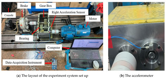
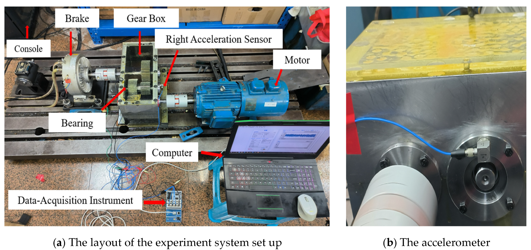
To verify the effectiveness of the established dynamic model under no external impact conditions, a test bench for the gear–shaft-bearing transmission system was set up for validation. As shown in Figure 4, the experimental system consists primarily of a control console, a magnetic powder brake, a two-stage parallel-shaft gearbox, acceleration sensors, a motor, a data acquisition instrument, and a computer. The three-phase motor is connected to the gearbox input shaft via a coupling and serves as the power source for the coupling system. The magnetic powder brake is connected to the output end of the gearbox through another coupling and acts as the loading device. The input speed of the motor and load of the magnetic powder brake applied to the gearbox are controlled by a control console system. Detailed information regarding the gearbox and operating conditions can be referred to in Table 2.
Figure 4.
Experimental set up of the gear–shaft-bearing transmission system.
Table 2.
Main parameters and operation condition setting of the gear transmission system.
In the data acquisition unit of the test rig, an IEPE-type triaxial accelerometer (model: A27F100; measurement range: ±50 g; frequency range: 0.5–5000 Hz) was adopted and mounted on the housing of the secondary transmission gearbox, with its specific installation position illustrated in Figure 4b. The data acquisition (DAQ) system consists of an NI cDAQ-9185 chassis and an NI 9234 DAQ module. The NI 9234 module is equipped with four acquisition channels with 24-bit resolution, which supports a maximum sampling rate of 512 kHz for analog signals. The data acquisition process was implemented via LabVIEW 2025 software, and all collected data were stored on a computer for subsequent analysis.
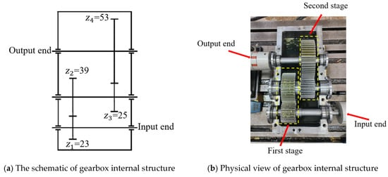
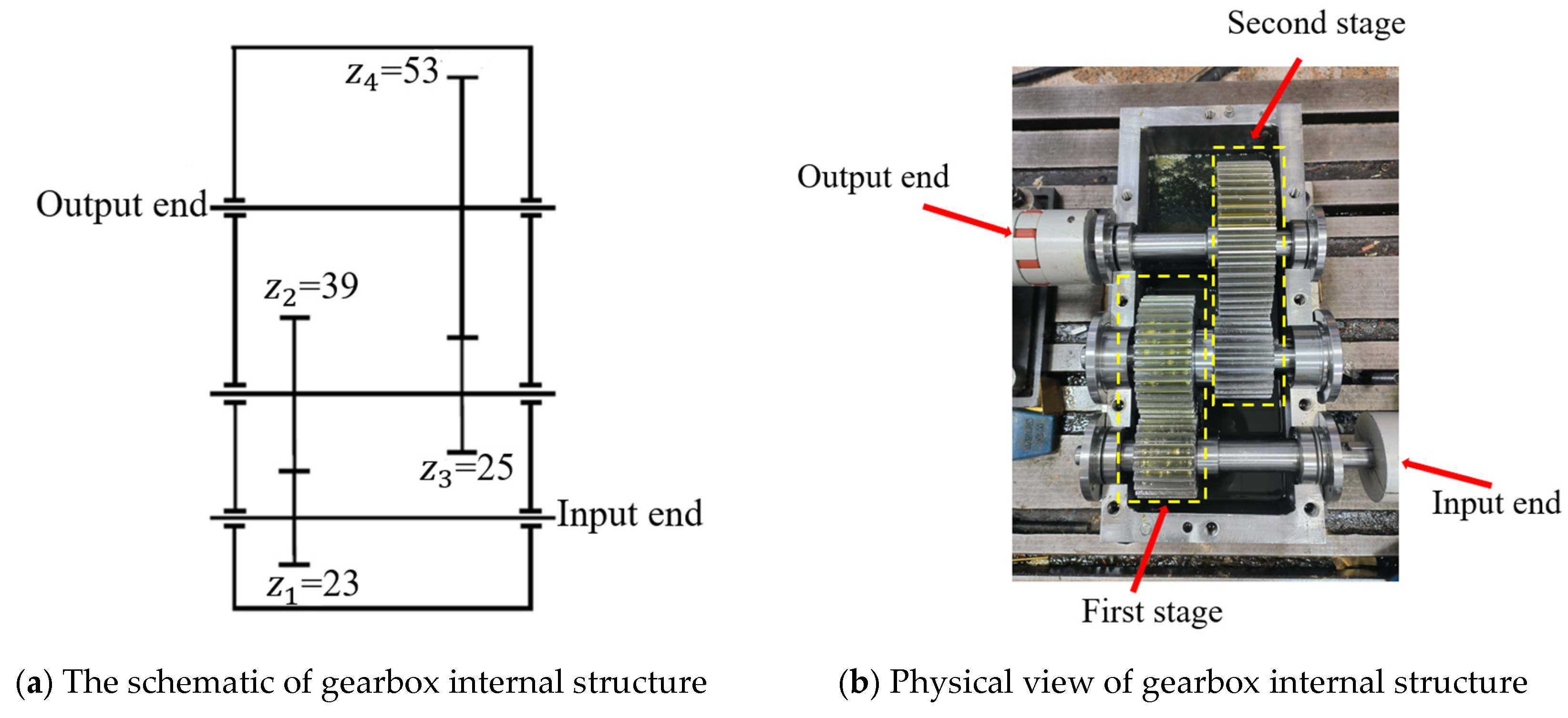
The gearbox serves as the core component of the simulation test rig, and the schematic and physical diagrams of its internal structure are shown in Figure 5a and Figure 5b, respectively. It can be seen from the figures that the gearbox is a two-stage spur gear reduction transmission system, consisting of two pairs of meshing gears and three transmission shafts.
Figure 5.
Structure diagram of gearbox.
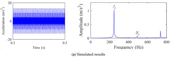
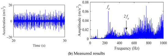
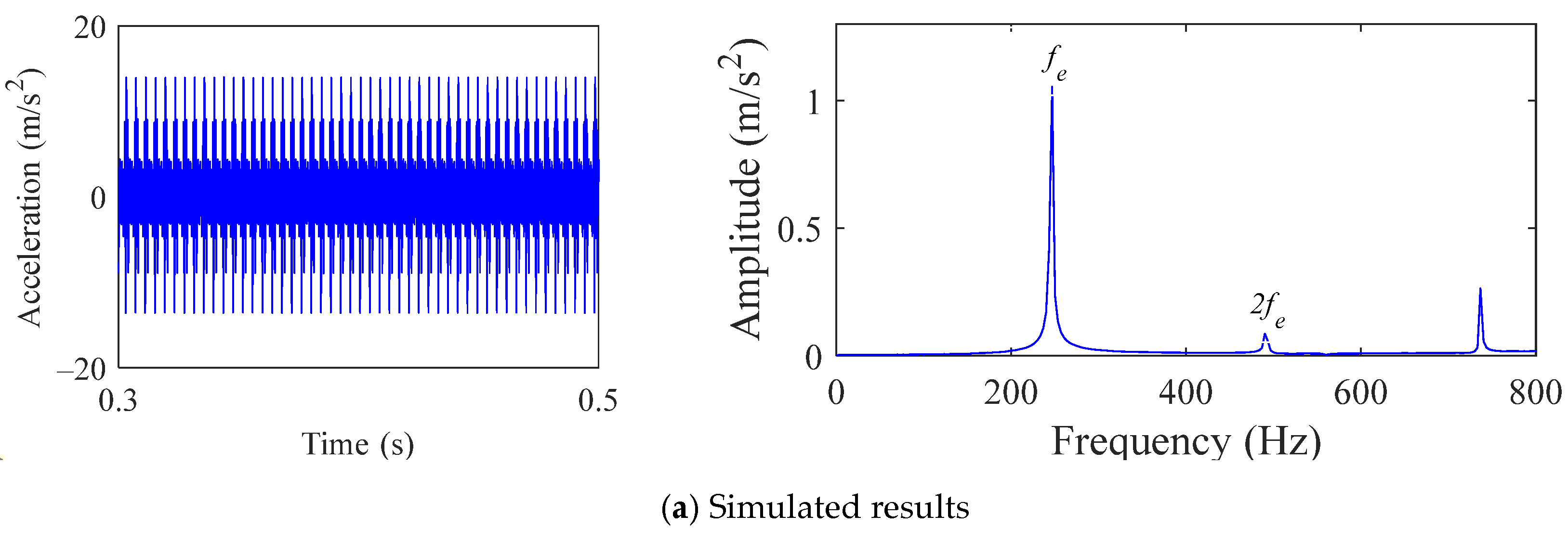
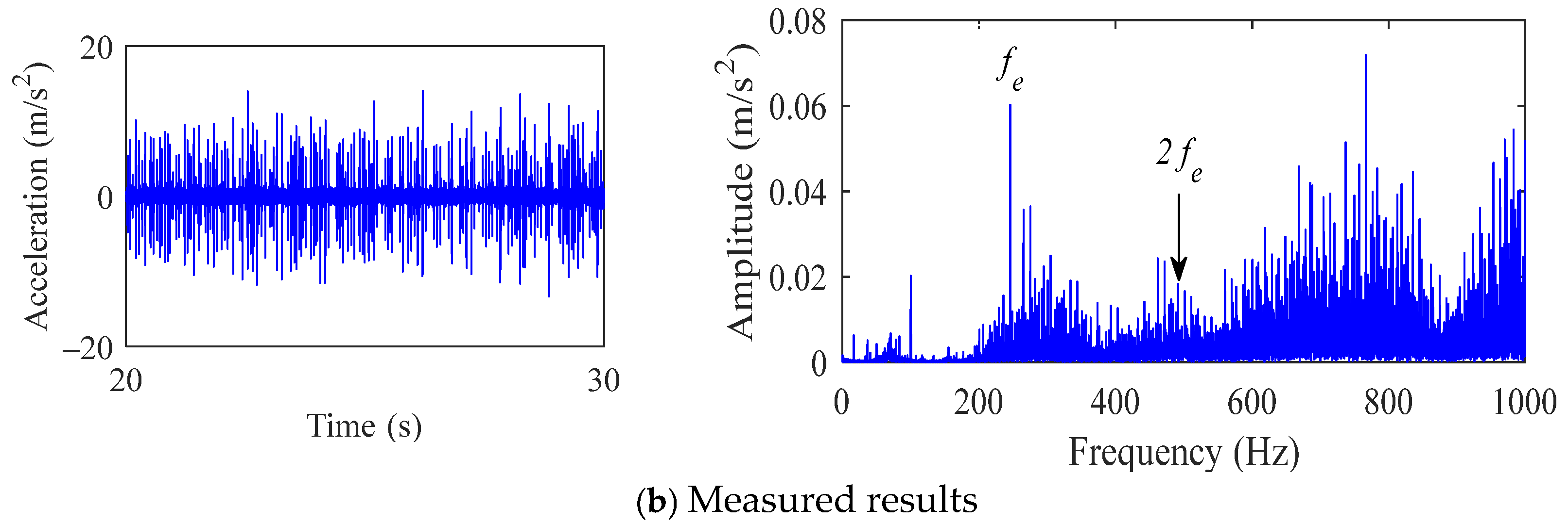
The operating conditions of the test are set as follows: an input rotational speed of 1000 r/min and an output load of 221.75 Nm. The parameters of the meshing gears refer to the main parameters of the secondary gears in Table 2. To verify the effectiveness of the proposed model, the measured vibration signals were collected and compared with the simulation results under the same operating conditions from both the time-domain and spectrum aspects. The specific comparisons are shown in Figure 4.
By comparing Figure 6a,b, it can be seen that the amplitude of the vibration response obtained through simulation is larger than that of the experimental results. The RMS value of the simulated vibration acceleration is 2.75 m/s2, and that of the experimental vibration acceleration is 2.2 m/s2, with a relative error of 20%. While these differences are noticeable, they fall within the common range for studies. The possible reason is that the sensor in the experiment is placed on the outside of gearbox, and the measured vibrations are attenuated, due to the dissipation of vibration energy. By comparing the frequency-domain characteristics of the simulation and experimental signals, it can be found that the dominant frequencies (meshing frequency fe and its second harmonic 2fe) are consistent, which is in line with the theoretical frequency characteristics. The difference is that the experimental results contain more narrowband colored noise caused by bearing and structure resonance, and broadband white noise caused by environment, electric noise and quantification process from the sensor and measurement system. By comparing the simulation values of the meshing frequency and its second harmonic with the corresponding theoretical and experimental values, the results are basically consistent. This proves the validity of the model in this paper and lays a solid foundation for the subsequent analysis.
Figure 6.
Comparison between the simulated and experimental signals in vertical direction.
5. Results and Discussion
5.1. External Impacts on Vibration Characteristics of the Gear System
The influence of external impacts on the vibration characteristics of the gear system is investigated by setting = 50,000 N, = 0.05 s, and = 0.001 s. A comparative analysis is conducted between the simulated signals of the gear system with and without external impacts.
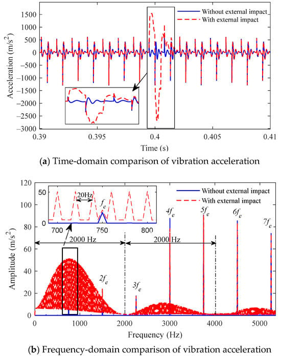
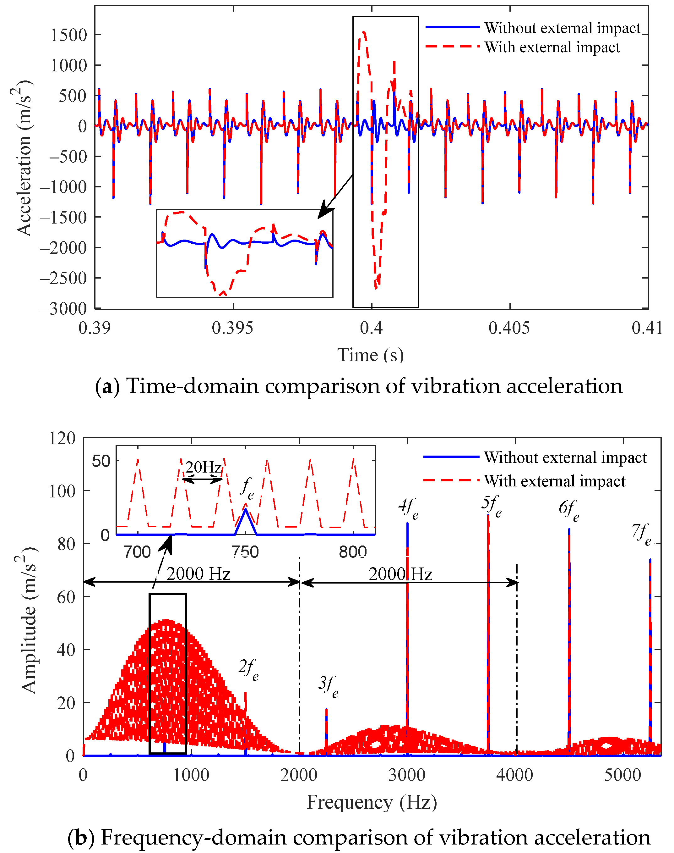
Figure 7 shows the time–frequency comparison of the driving gear’s vibration acceleration in the y-axis with and without external impacts. Figure 7a presents the time-domain comparison of the driving gear’s y-axis vibration acceleration with and without external impacts. The y-axis vibration acceleration of the driving gear under external impacts is significantly greater than that without external impacts. The gear vibration velocity curve sequentially generates positive and negative pulse impact peaks at the moment of impact, followed by a smaller-amplitude positive pulse impact peak before gradually returning to the normal operating state. This phenomenon is attributed to the transmission of impact forces from the bearing end through the shaft to the gears, leading to a sharp surge in vibrational acceleration. Upon the cessation of the impact, the resulting reaction force from the shaft causes a rapid reversal in vibration acceleration. Subsequently, as the reaction force attenuates, the vibrational acceleration eventually recovers to its steady-state operating condition.
Figure 7.
Time–frequency comparison of vibration acceleration for driving gear in y-axis.
The y-axis vibration acceleration spectra of the driving gear under both conditions—with and without external impacts—are compared (Figure 7b) to reveal the influence of external impacts on gear vibration signals in the frequency domain. The spectrum only contains meshing frequency fe and its harmonics without external impacts. However, the spectrum exhibits these frequency components and numerous modulation sidebands with external impacts. Each sideband has the same bandwidth (e.g., 2000 Hz under the given operating condition), and the amplitude of the sidebands decreases progressively from low to high frequencies. The frequency characteristics of the system’s vibration response become significantly more complex.
As shown in Figure 7b, the meshing frequency components in the spectrum are submerged within the modulation sidebands under external impacts. The adjacent frequency components within these sidebands are uniformly spaced at 20 Hz. Additionally, the amplitudes differ significantly at 2fe, 4fe, and 6fe under the two conditions. The frequency-domain analysis indicates that external impacts induce pronounced sideband modulation, which deteriorates the stability of the gear system.
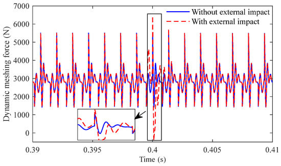
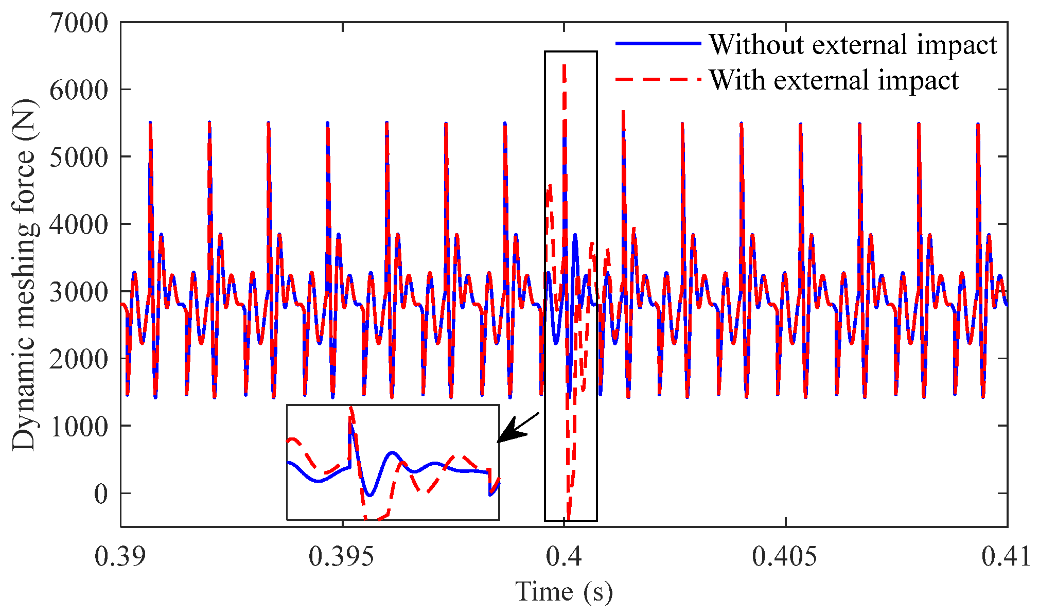
Dynamic meshing force serves as the primary excitation source in gear systems and significantly influences their vibration characteristics. Therefore, the variation patterns of dynamic meshing force with and without external impacts can explain the mechanisms behind changes in gear vibration behavior. Figure 8 compares the dynamic meshing force in gear pairs with and without external impacts. The dynamic meshing force curve exhibits distinct periodicity under normal operation (without external impacts), with the minimum meshing force consistently remaining above zero. However, when subjected to external impacts, the meshing force curve shows intense impact peaks at the moment of shock, which causes the minimum meshing force to drop below zero. The gear transmission system experiences bilateral impact.
Figure 8.
Comparison of dynamic meshing force.
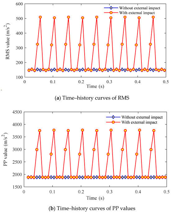
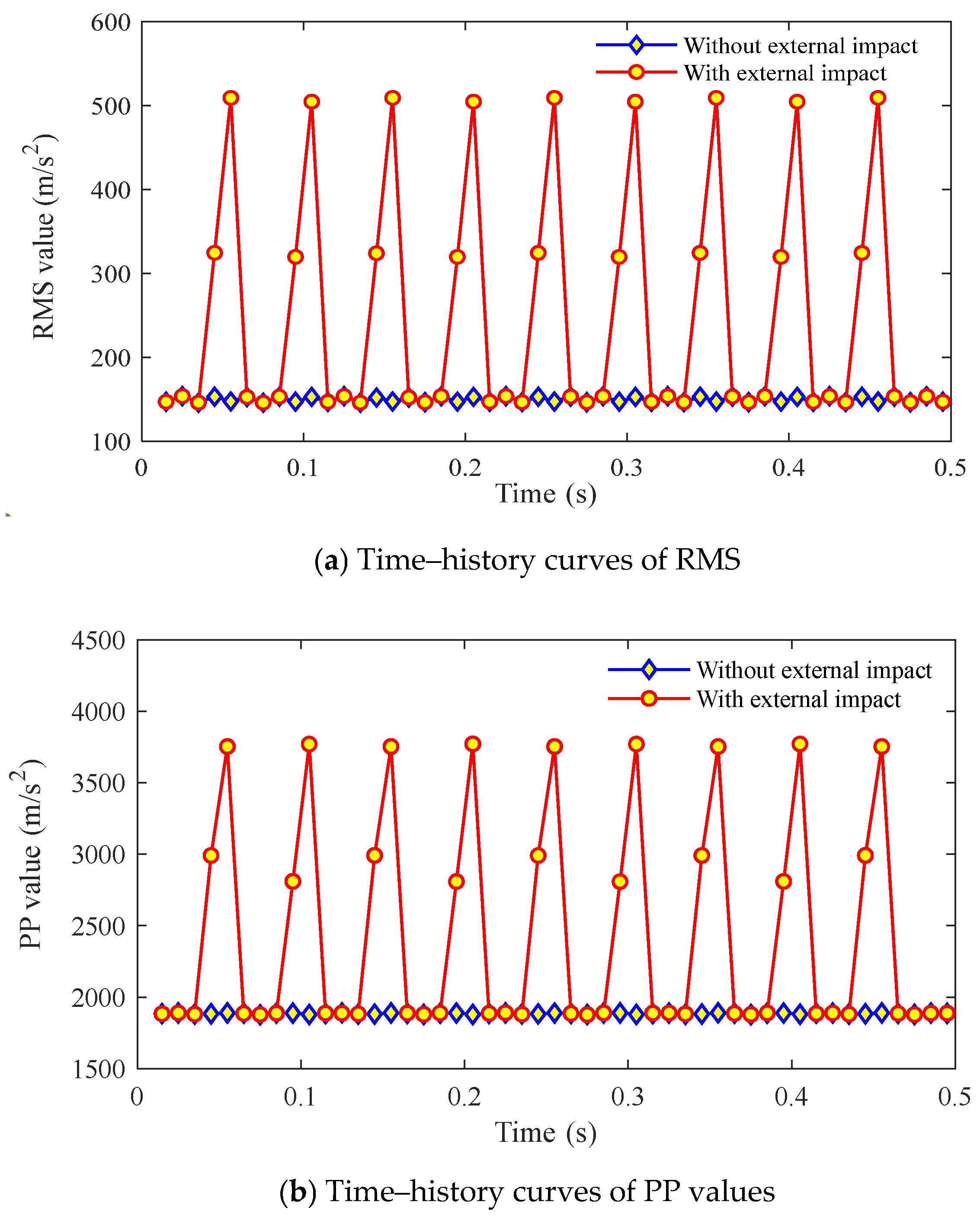
Two common time-domain evaluation metrics—root mean square (RMS) and peak-to-peak (PP) value—are selected for vibration assessment to quantitatively evaluate the influence of external impacts on gear vibration characteristics. The vibration acceleration signal in the y-axis of the driving gear is analyzed without loss of generality. Using a fixed time interval of = 0.01 s, the RMS and PP values of the vibration acceleration signal are calculated for different time intervals throughout the entire operating process.
Figure 9 shows the time-varying curves of RMS and PP values of the driving gear’s y-axis vibration acceleration with/without external impacts. Both RMS and PP curves remain relatively stable with minor fluctuations without external impacts, indicating smooth operation. In contrast, when subjected to external impacts, these curves demonstrate dramatic fluctuations where each impact event triggers an abrupt increase in both RMS and PP values. External impacts can significantly promote the vibration intensity of gear pairs and the generation of impact components in the gears, which leads to instability in system operation.
Figure 9.
Time-varying curves of statistical indicators for y-axis vibration acceleration of the driving gear.
When a bearing is subjected to an impact, the vibration signal of the gear system exhibits non-stationary characteristics, with its frequency varying significantly over time. Traditional fast Fourier transform (FFT)-based spectral analysis methods fail to capture the correlation between time and frequency due to the loss of temporal information. Therefore, the short-time Fourier transform (STFT) is employed to perform time–frequency analysis on the non-stationary vibration signals of the gear system under external impacts. This approach accurately reflects the local time-varying frequency characteristics of the vibration signals, providing a more comprehensive understanding of the frequency variation patterns in the gear meshing process under external impacts. In this study, the Hann window was employed, with a window length of 4096 samples and an overlap ratio of 75%, and a resulting frequency resolution of approximately 244 Hz. This configuration effectively captures the time-varying frequency characteristics of the non-stationary vibration signals in the gear system under external impact, while ensuring sufficient resolution for distinguishing harmonic components.
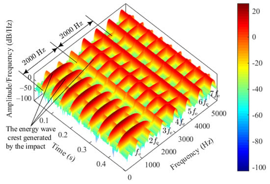
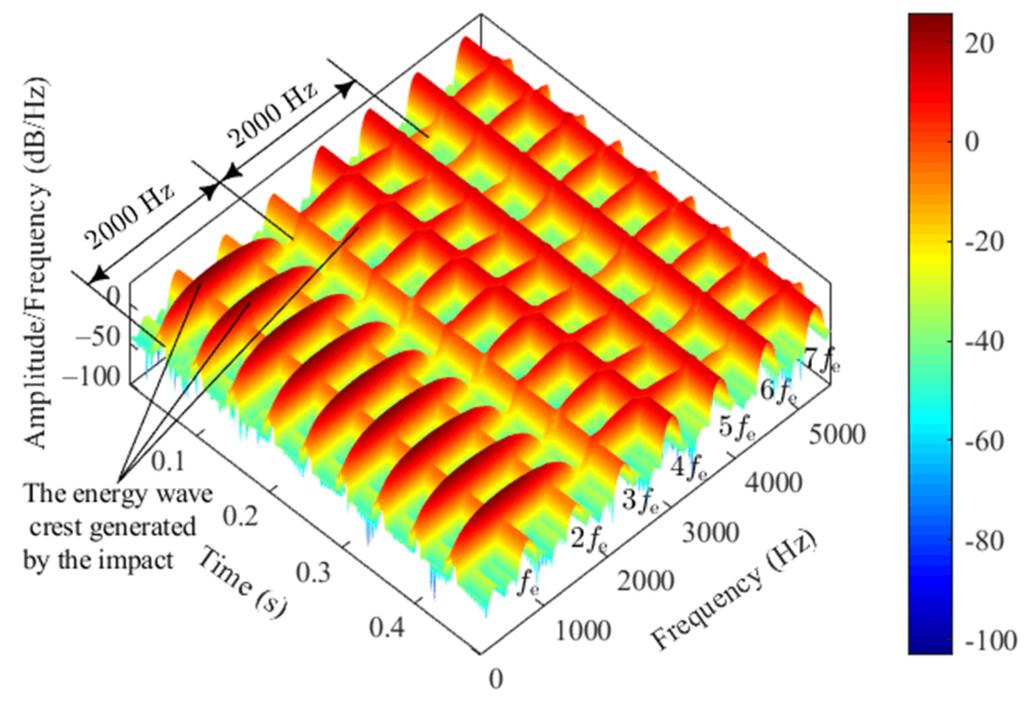
Figure 10 shows the time–frequency distribution of the vibration acceleration signal in the y-axis of the driving gear under external impacts. Distinct meshing frequency and its harmonics are observed throughout the operation. Additionally, each instant impact generates multiple energy peaks in the time–frequency domain, with the same frequency span (2000 Hz). The amplitude of these energy peaks progressively decreases from low to high frequencies, which aligns with the sideband spectrum analysis earlier. The amplitude of impact-induced energy peaks substantially exceeds that of the meshing frequency () and its second harmonic () in the low frequency, with a marked difference in magnitude. In contrast, the high-frequency region is dominated by the harmonic energy of the meshing frequency. External impacts primarily affect the gear system’s vibration response at low frequencies.
Figure 10.
Time–frequency characteristics of y-axis vibration acceleration of the driving gear.
5.2. Impact Load Amplitude
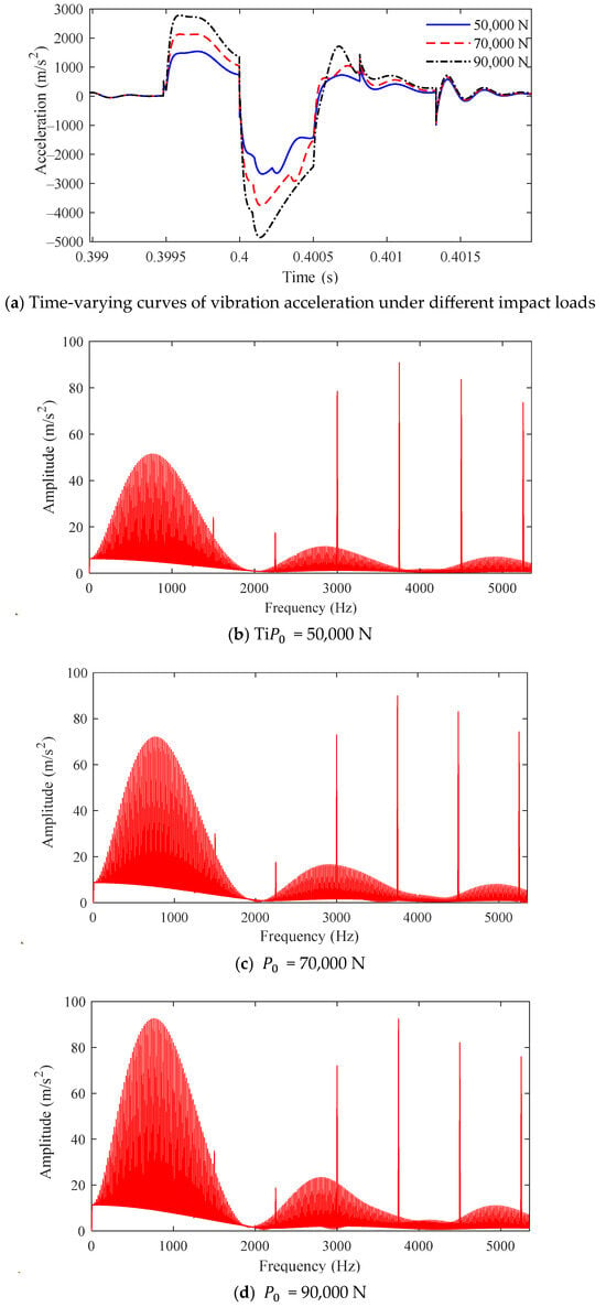
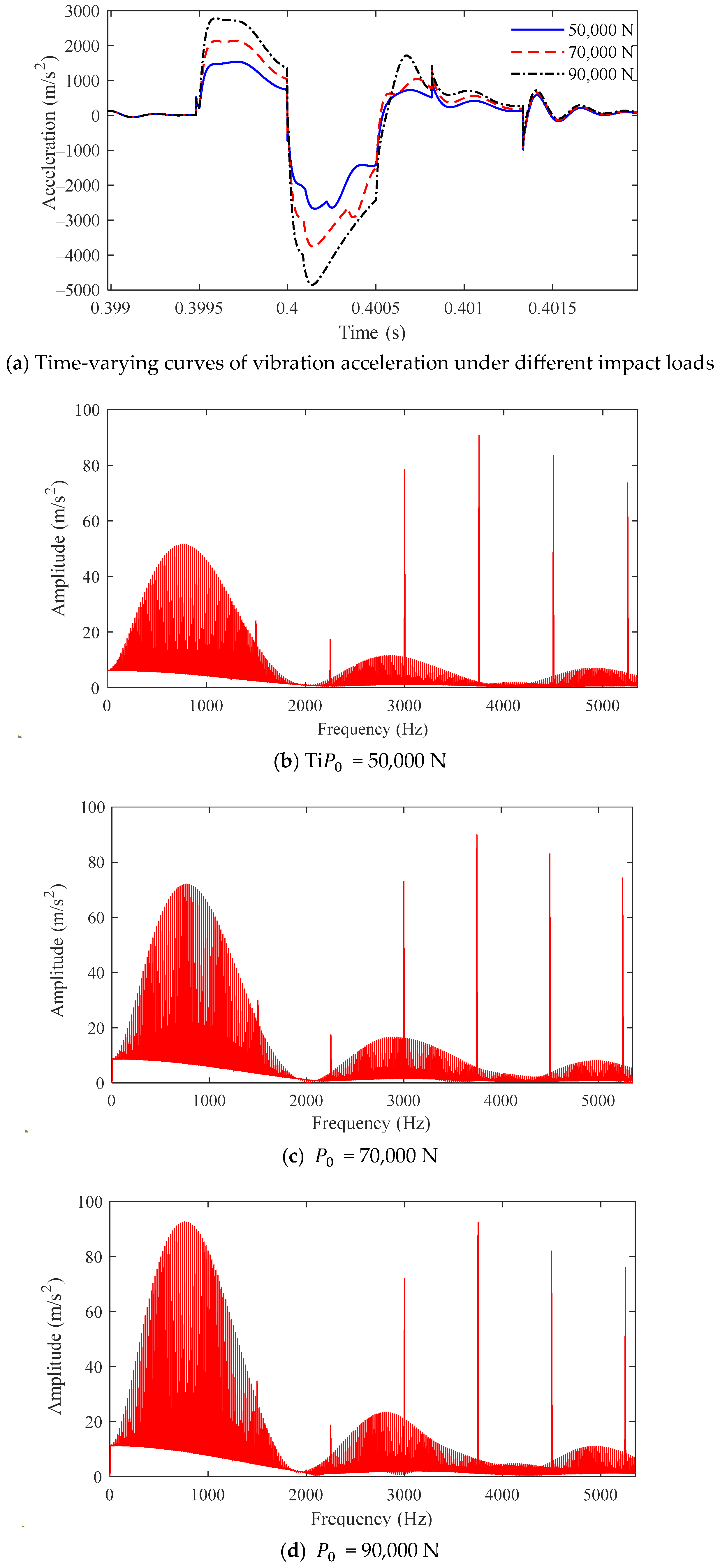
Parameters are set as ∆T = 0.05 s and ∆τ = 0.001 s to investigate the influence of impact load amplitude on the vibration response characteristics of the gear system under external impacts. Dynamic simulations of the gear pair under external impacts are conducted by applying different impact load amplitudes, which yields vibration response signals under varying impact loads (Figure 11).
Figure 11.
Vibration response of the driving gear in the y-axis under different impact loads.
Figure 11a presents the time-domain curves of vibration acceleration in the y-axis of the driving gear under different impact loads. As the impact load increases from 50 kN to 90 kN under external impacts, the peak amplitude of the shock-induced acceleration spikes grows significantly; however, the duration of the resulting vibration fluctuations remains unchanged. Figure 11b–d display the corresponding frequency spectra of the y-axis vibration acceleration under varying impact loads. The magnitudes of modulation sidebands increase in the vibration acceleration spectra with the increased impact load.
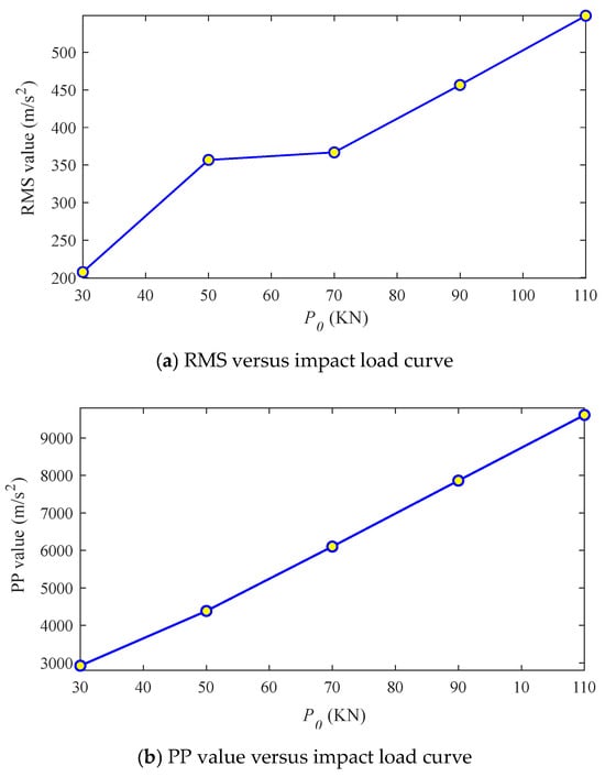
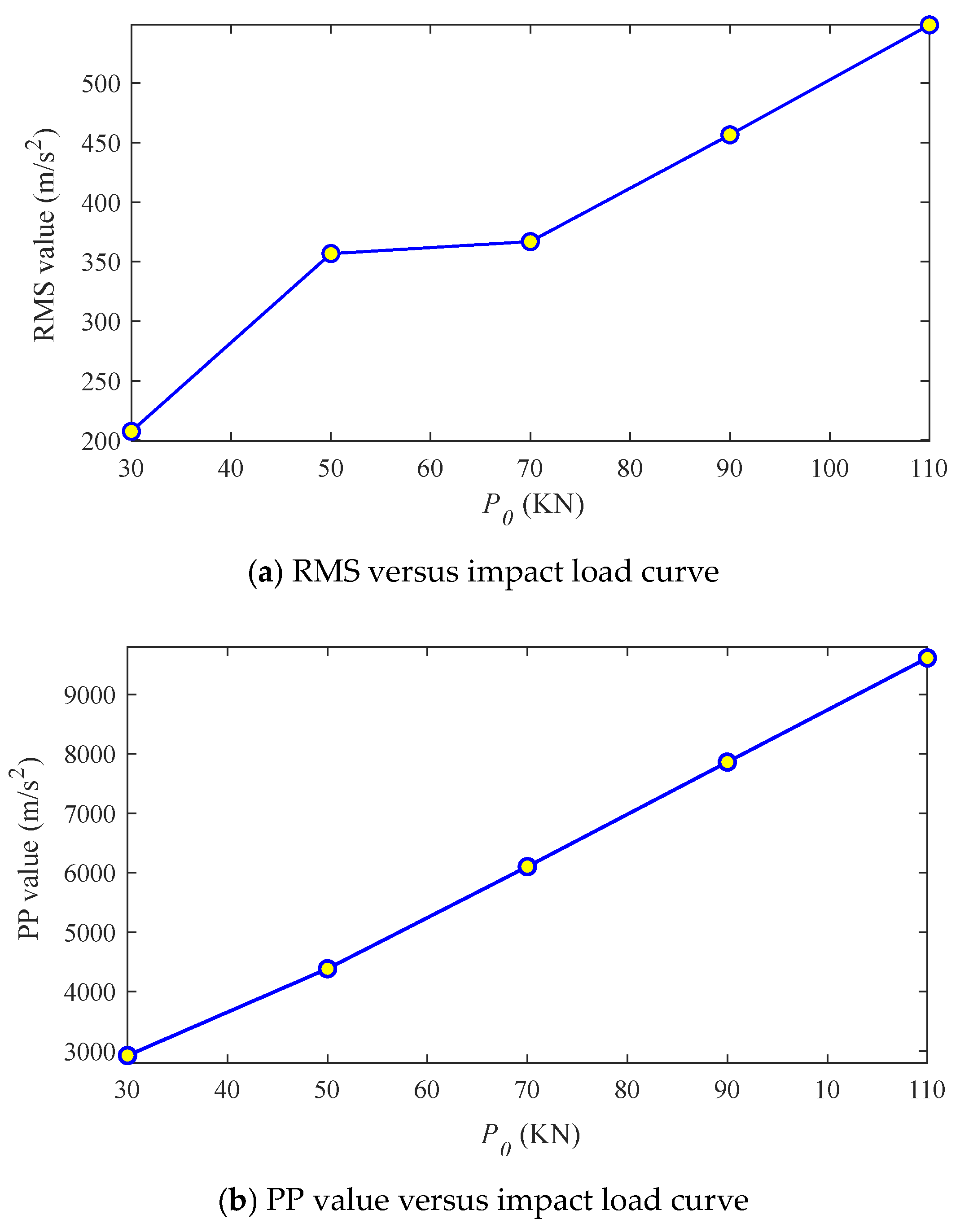
Figure 12 shows the statistical indicators of the driving gear’s vibration acceleration in the y-axis under different external impact loads. Figure 12a presents the RMS of the driving gear’s y-axis vibration acceleration versus impact load amplitude. The RMS increases with the increased impact load. Figure 12b displays the PP values of the driving gear’s y-axis vibration acceleration versus impact load. The PP values exhibit an approximately linear increasing trend with higher impact loads. Larger external impact loads result in stronger vibrational impacts between the gear pair.
Figure 12.
Curves of statistical indicators of y-axis vibration acceleration of the driving gear versus impact loads.
5.3. Impact Effect Duration
Impact duration is a critical factor affecting the system’s impact characteristics. Parameters are set as P0 = 50,000 N and = 0.05 s to investigate how impact duration influences the vibration response of the gear system under external impacts. The vibration signals of the gear pair under external impacts are obtained through dynamic simulations at different impact durations.
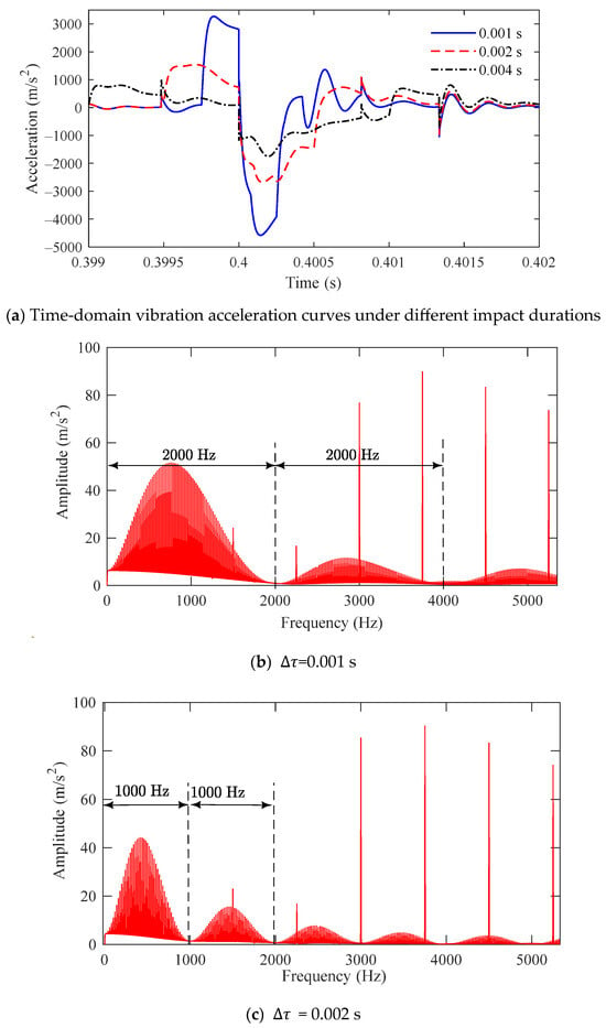
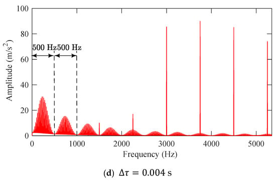
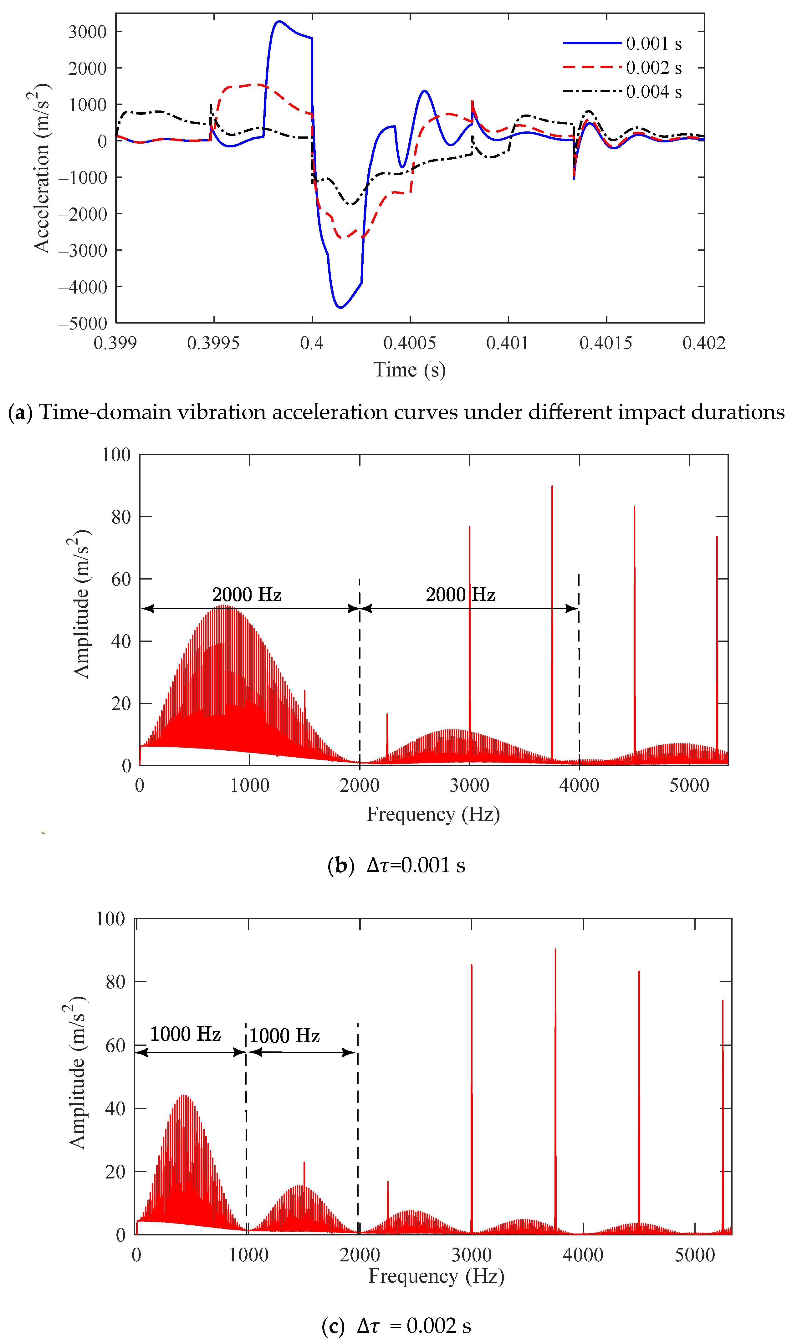
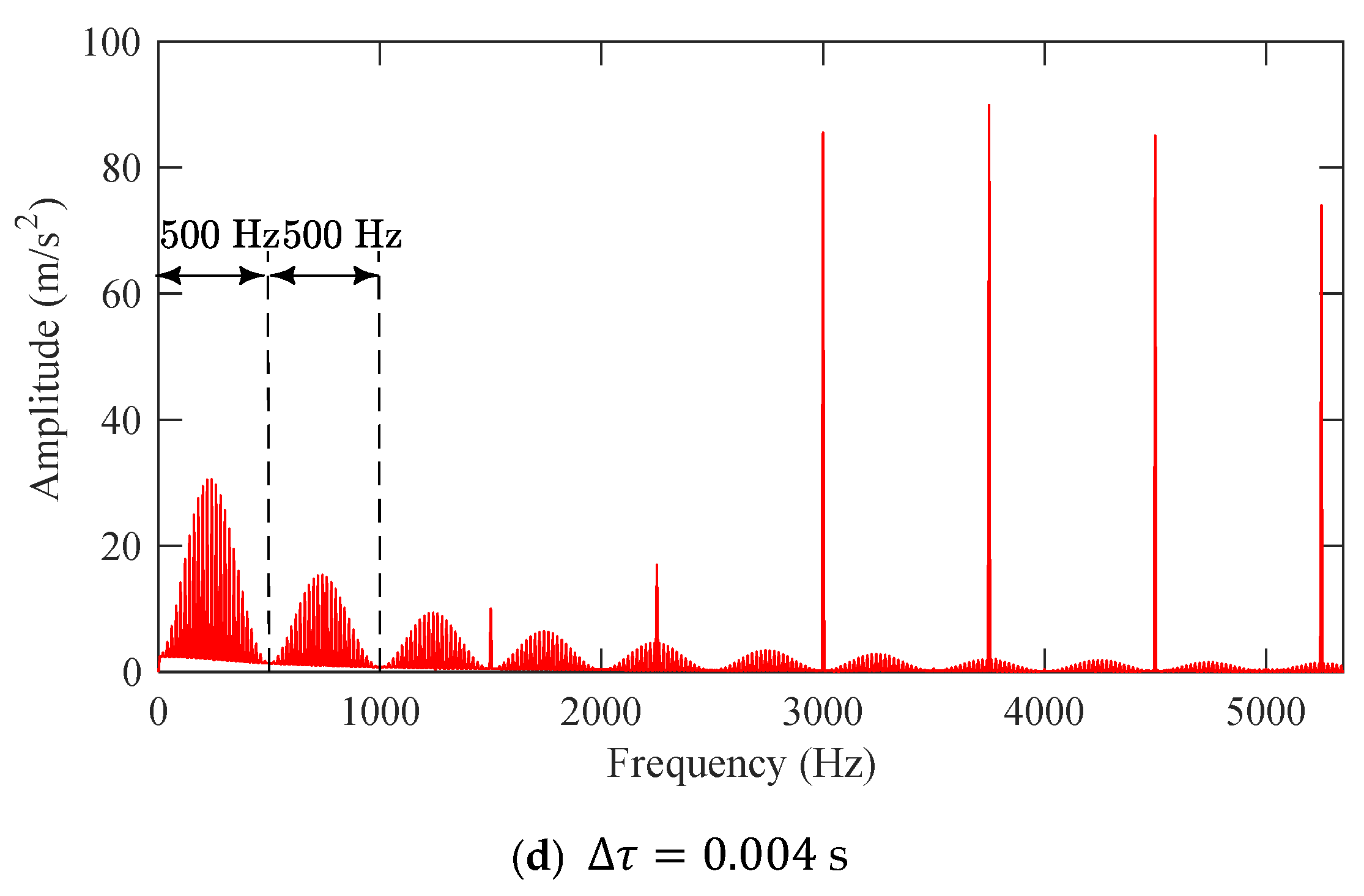
Figure 13 shows the y-axis vibration response of the driving gear under different impact durations. Figure 13a presents the time-domain curves of the y-axis vibration acceleration under varying impact durations. As the impact duration increases, the vibration acceleration exhibits prolonged fluctuations with reduced peak amplitudes. Figure 13b–d display the corresponding frequency spectra of y-axis vibration acceleration. When is the impact duration, is the width of each modulation sideband in the spectrum. Furthermore, longer impact durations reduce sideband amplitudes. Therefore, the impact duration affects gear vibration signals through amplitude modulation and frequency modulation.
Figure 13.
Vibration response of the driving gear in the y-axis under varying impact durations.
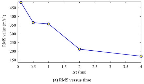
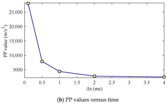
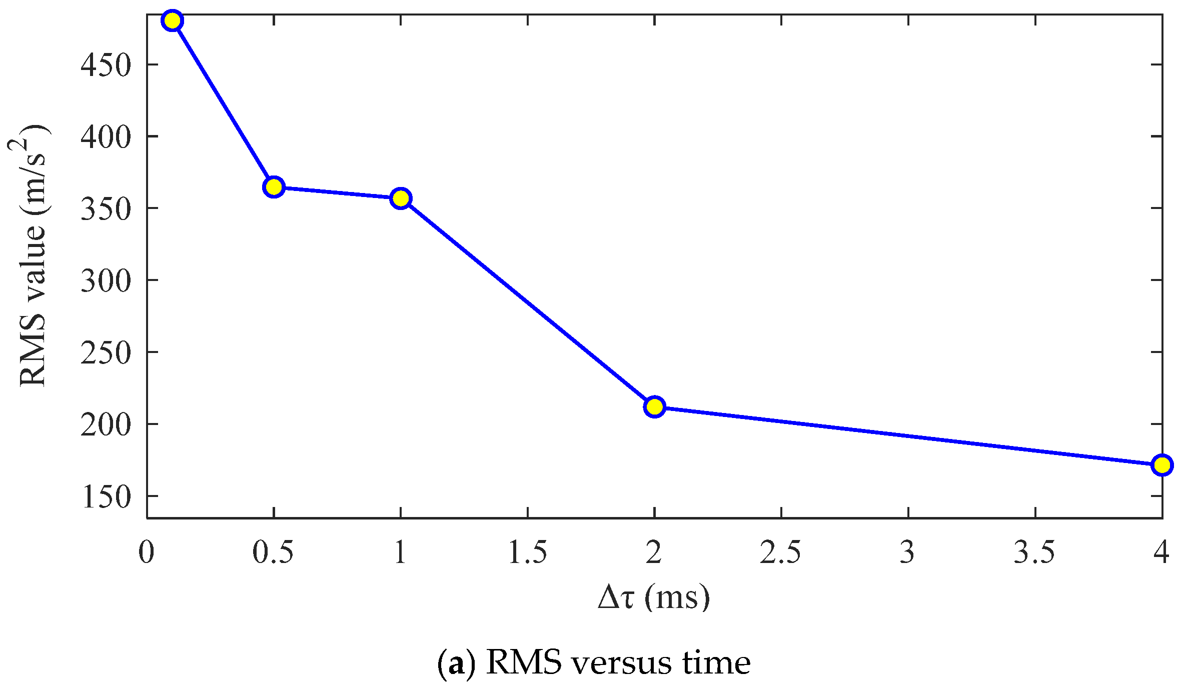
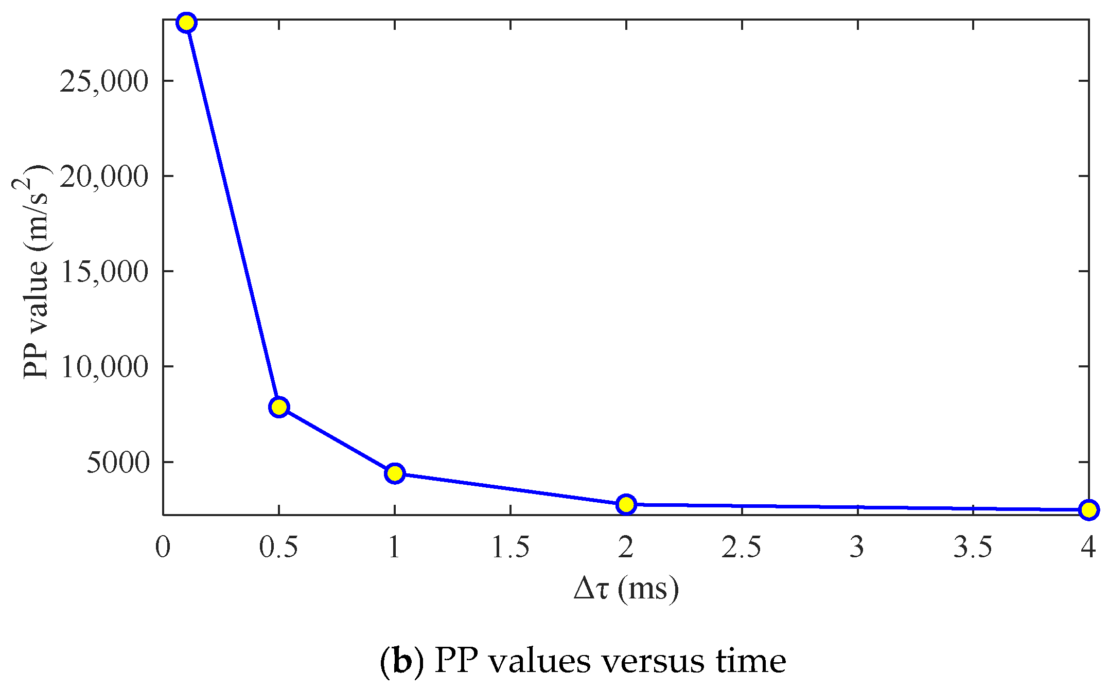
Figure 14 shows the statistical indicators of the driving gear’s y-axis vibration acceleration versus impact duration. Figure 14a presents the RMS of y-axis vibration acceleration under varying impact durations. As the impact duration increases, the RMS of gear vibration signals generally decreases. Shorter impact durations result in higher vibrational energy between gear pairs. Figure 14b illustrates the PP values of the y-axis vibration acceleration versus impact duration. Longer impact durations lead to smaller PP vibration amplitudes. The change rate is more pronounced at shorter durations and gradually stabilizes with longer durations. The shortened impact duration intensifies gear impact. A shorter impact duration results in a more rapid change in impact. This accelerates the frequency of variations in the system’s stress state, which exacerbates gear impact.
Figure 14.
Curves of statistical indicators of y-axis vibration acceleration of the driving gear with impact duration.
6. Conclusions
The work established a bending–torsion coupled dynamic model of a gear–shaft-bearing transmission system and considered the external impacts. The influence of external impacts on the vibration characteristics of the gear system was investigated, with the variation patterns of vibration characteristics under different external impact loads and durations analyzed. The main conclusions are as follows.
(1) External impacts significantly intensify the instantaneous shock effect in gear transmission systems. In addition to increasing vibration amplitudes, such impacts further exacerbate the meshing shock during the operation of gear pairs and aggravate the collision between gear teeth, thereby further enhancing the instability of system motion and directly impairing the operational accuracy of the system.
(2) Spectral analysis confirms that external impacts induce complex sideband modulation, and their influence on the vibration response frequency of the system is mainly concentrated in the low-frequency range. Meanwhile, they substantially increase the vibrational energy of the system and facilitate the generation of shock components. Therefore, external impacts should be avoided as much as possible during the actual operation of gear transmission systems.
(3) The modulation characteristics of the system exhibit significant differences with the variation in impact characteristics. The impact amplitude primarily dominates the amplitude modulation effect, while the variation in impact duration induces a coupled amplitude–frequency modulation effect. An increase in external impact load and a reduction in impact duration both serve to intensify the shock acting on the gear transmission system.
It should be noted that the model developed in this paper does not consider lubrication effects. A more accurate model incorporating lubrication is currently under development. Furthermore, experimental measurements on the vibration characteristics of gear transmission systems under external impact excitation will be conducted in future work.
Author Contributions
Conceptualization, D.H. and W.T.; methodology, D.H.; software, G.Z.; validation, G.Z.; formal analysis, G.Z.; investigation, D.H.; resources, W.T.; data curation, G.Z.; writing—original draft preparation, G.Z.; writing—review and editing, C.Z. and W.Y.; visualization, Z.T.; supervision, W.T.; project administration, W.T.; funding acquisition, W.T., W.Y. and C.Z. All authors have read and agreed to the published version of the manuscript.
Funding
The work is supported by the National Natural Science Foundation of China (52365010, 52505101, 52475087, 52262049), the Science and Technology Project of Jiangxi Province (20242BAB25262), and the Early-Career Young Scientists and Technologists Project of Jiangxi Province (20252BEJ730175).
Data Availability Statement
The datasets generated and/or analyzed during the current study are available from the corresponding author on reasonable request.
Conflicts of Interest
The authors have no relevant financial or non-financial interests to disclose.
References
- Qiao, Z.; Zhou, J.; Sun, W.; Zhang, X. A coupling dynamics analysis method for two-stage spur gear under multisource time-varying excitation. Shock Vib. 2019, 2019, 7350701. [Google Scholar] [CrossRef] [Scilit]
- Xu, M.; Han, Y.; Sun, X.; Shao, Y.; Gu, F.; Ball, A.D. Vibration characteristics and condition monitoring of internal radial clearances within a ball bearing in a gear-shaft-bearing system. Mech. Syst. Signal Process. 2022, 165, 108280. [Google Scholar] [CrossRef] [Scilit]
- Tu, W.; Liang, J.; Yu, W.; Shi, Z.; Liu, C. Motion stability analysis of cage of rolling bearing under the variable-speed condition. Nonlinear Dyn. 2023, 111, 11045–11063. [Google Scholar] [CrossRef] [Scilit]
- Tu, W.; Liu, C.; Wang, H.; Hu, D.; Yu, W. Influences of external moment on the contact characteristics of aSngular contact ball bearings under combined loads. Int. J. Non-Linear Mech. 2024, 161, 104698. [Google Scholar] [CrossRef] [Scilit]
- Zeng, Q.; Liu, Y.; Du, W.; Jiang, L.; Yu, W. Dynamic characteristic analysis of a gear-rotor-bearing coupling system considering bearing fit. Nonlinear Dyn. 2025, 113, 2131–2154. [Google Scholar] [CrossRef] [Scilit]
- Liu, G.; Hong, J.; Parker, R.G. Influence of simultaneous time-varying bearing and tooth mesh stiffness fluctuations on spur gear pair vibration. Nonlinear Dyn. 2019, 97, 1403–1424. [Google Scholar] [CrossRef] [Scilit]
- Wang, F.; Dai, P.; Wang, J.; Niu, L. Vibration Responses of the Bearing-Rotor-Gear System with the Misaligned Rotor. Machines 2022, 10, 267. [Google Scholar] [CrossRef] [Scilit]
- Dai, P.; Wang, J.; Yan, S.; Huang, S.; Wang, F.; Liu, J. Vibration characteristics of the gear shaft-bearing system with compound defects under variable operating conditions. Proc. Inst. Mech. Eng. Part K J. Multi-Body Dyn. 2022, 236, 113–129. [Google Scholar] [CrossRef] [Scilit]
- Mo, S.; Wang, Z.; Zeng, Y.; Zhang, W. Nonlinear Vibration Analysis of the Coupled Gear-Rotor-Bearing Transmission System for a New Energy Vehicle. Int. J. Bifurcat. Chaos 2023, 33, 2350105. [Google Scholar] [CrossRef] [Scilit]
- Ouyang, T.; Su, Z.; Li, S.; Huang, G.; Chen, N. Experimental and numerical investigations on dynamic characteristics of gear-roller-bearing system. Mech. Mach. Theory 2019, 140, 730–746. [Google Scholar] [CrossRef] [Scilit]
- Gao, D.; Gao, Z. Nonlinear dynamic characterization of sliding bearing-planetary gear system. J. Braz. Soc. Mech. Sci. Eng. 2025, 47, 41. [Google Scholar] [CrossRef] [Scilit]
- Ullah, N.; Xi, C.; Cong, T.; Yucheng, H. Rotordynamics analysis of a single helical gear transmission system for high speed applications. J. Mech. Eng. Sci. 2020, 14, 7040–7048. [Google Scholar] [CrossRef] [Scilit]
- Wang, X.; Zhu, Y.; Li, W.; Hu, D.; Zhang, X.; Chen, H. Vibration characteristics of triple-gear-rotor system in compressed air energy storage under variable torque load. Sci. Prog. 2021, 104, 291–312. [Google Scholar] [CrossRef] [Scilit] [PubMed]
- Lu, K.; Guo, D.; Zhu, W.; Jin, Y.; Cheng, H.; Gu, X.; Fu, C. Nonlinear Dynamic Behavior Analysis of Dual-Rotor-Bearing Systems with Looseness and Rub–Impact Faults. AIAA J. 2023, 61, 5164–5175. [Google Scholar] [CrossRef] [Scilit]
- Zhang, H.; Li, S.; Sun, H. Study on the Vibration Characteristics of the Helical Gear-Rotor-Bearing Coupling System of a Wind Turbine with Composite Faults. Mathematics 2024, 12, 1410. [Google Scholar] [CrossRef] [Scilit]
- Liu, Y.; Liu, C.; Li, T.; Hu, P.; Feng, C.; Wang, Y. Research on ball bearing stiffness considering the uncertain bearing-shaft interference fit. Proc. Inst. Mech. Eng. Part C J. Mech. Eng. Sci. 2025, 239, 8073–8089. [Google Scholar] [CrossRef] [Scilit]
- Fu, C.; Zhao, H.; Zhang, Y.; Zheng, L.; Lu, K. Coupled axial-lateral-torsional stochastic dynamics of a rotor-bearing system subjected to periodic pulse and unbalanced excitations. J. Sound Vib. 2026, 621, 119461. [Google Scholar] [CrossRef] [Scilit]
- Zhang, C.; Yu, W.; Zhang, Y.; Xu, J.; Zeng, Q.; Li, L.; Wang, L.; Huang, W. Dynamics modeling and analysis of the multistage planetary gear set-bearing-rotor-clutch coupling system considering the tooth impacts of clutches. Mech. Syst. Signal Process. 2024, 214, 111365. [Google Scholar] [CrossRef] [Scilit]
- Shi, J.; Gou, X.; Zhu, L. Modeling and analysis of a spur gear pair considering multi-state mesh with time-varying parameters and backlash. Mech. Mach. Theory 2019, 134, 582–603. [Google Scholar] [CrossRef] [Scilit]
- Zhang, C.; Yu, W.; Wu, J.; Wang, L.; Ding, X.; Huang, W.; Chen, X. Dynamic analysis of gear pairs considering the actual contact state of truncated asperities on the 3D rough surfaces and force-dependent mesh stiffness. Nonlinear Dyn. 2024, 112, 13971–13993. [Google Scholar] [CrossRef] [Scilit]
- Shi, H.; Chen, W.; Li, J.; Wang, Z.; Jiang, L. Vibration stability and bifurcation analysis of spur gear systems based on time-varying backlash and random load. Int. J. Non-Linear Mech. 2024, 160, 104648. [Google Scholar] [CrossRef] [Scilit]
- Zhang, C.; Li, Z.; Xu, J.; Zhang, W.; Yu, W.; Tu, W.; Wang, L.; Huang, W. Dynamic impact modeling and analysis of the floating-supported friction plate and inner hub system considering tooth root cracks. Sci. China Technol. Sci. 2026, 69, 1220801. [Google Scholar] [CrossRef] [Scilit]
- Cao, Z.; Chen, Z.; Jiang, H. Nonlinear dynamics of a spur gear pair with force-dependent mesh stiffness. Nonlinear Dyn. 2020, 99, 1227–1241. [Google Scholar] [CrossRef] [Scilit]
- Dou, S.; Liu, W. Analysis of the dynamic contact behaviour of high-speed train transmission gear excited by wheel defects. Proc. Inst. Mech. Eng. Part F J. Rail Rapid Transit 2024, 238, 1212–1223. [Google Scholar] [CrossRef] [Scilit]
- Yuan, Y.; Wang, J.; Yang, M. Nonlinear dynamics simulation of the helical gear transmission system for high-speed train. J. Vib. Control 2024, 31, 981–993. [Google Scholar] [CrossRef] [Scilit]
- Chen, Z.; Zhai, W.; Wang, K. Locomotive dynamic performance under traction/braking conditions considering effect of gear transmissions. Veh. Syst. Dyn. 2018, 56, 1097–1117. [Google Scholar] [CrossRef] [Scilit]
- Jiang, H.; Dai, Y.; Liu, F.; Li, B. Dynamic responses of the high-speed train with polygonal wheels considering gear transmissions. Proc. Inst. Mech. Eng. Part C J. Mech. Eng. Sci. 2025, 239, 686–702. [Google Scholar] [CrossRef] [Scilit]
- Chen, H.; Wang, X.; Gao, H.; Yan, F. Dynamic characteristics of wind turbine gear transmission system with random wind and the effect of random backlash on system stability. Proc. Inst. Mech. Eng. Part C J. Mech. Eng. Sci. 2016, 231, 2590–2597. [Google Scholar] [CrossRef] [Scilit]
- Zhao, W.; Zhao, W.; Liu, J.; Yang, N. Effect of Turbulent Wind Conditions on the Dynamic Characteristics of a Herringbone Planetary Gear System of a Wind Turbine. Machines 2024, 12, 227. [Google Scholar] [CrossRef] [Scilit]
- Tong, Z.M.; Hu, Y.; Tong, S.; Jiang, Y.; Song, B. Dynamic modeling of spur gear system under marine ship heaving-pitching motion. Ocean Eng. 2023, 283, 115069. [Google Scholar] [CrossRef] [Scilit]
- Milojević, S.; Pešić, R.; Taranović, D. Tribological Principles of Constructing the Reciprocating Machines. Tribol. Ind. 2015, 37, 13–19. [Google Scholar]
- Tang, J.Y.; Peng, F.J.; Huang, Y.F. Numerical analysis of dynamic stress variation in spur gear under impact loads. J. Vib. Shock 2009, 28, 138–143. [Google Scholar]
- Steenbergen, M.J.M.M. The role of the contact geometry in wheel–rail impact due to wheel flats. Veh. Syst. Dyn. 2007, 45, 1097–1116. [Google Scholar] [CrossRef] [Scilit]
- Eckl, R.; Grisaro, H.Y. Maximum response of SDOF systems under consecutive triangular pulses. J. Sound Vib. 2026, 626, 119631. [Google Scholar] [CrossRef] [Scilit]
- Tian, X. Dynamic Simulation for System Response of Gearbox Including Localized Gear Faults. Ph.D. Thesis, University of Alberta, Edmonton, AB, Canada, 2004. [Google Scholar]
- Sainsot, P.; Velex, P.; Duverger, O. Contribution of gear body to tooth deflections—A new bidimensional analytical formula. J. Mech. Des. 2004, 126, 748–752. [Google Scholar] [CrossRef] [Scilit]
- Yi, Y.; Huang, K.; Xiong, Y.; Sang, M. Nonlinear dynamic modelling and analysis for a spur gear system with time-varying pressure angle and gear backlash. Mech. Syst. Signal Process. 2019, 132, 18–34. [Google Scholar] [CrossRef] [Scilit]
- Liu, H.; Zhang, C.; Xiang, C.; Wang, C. Tooth profile modification based on lateral-torsional-rocking coupled nonlinear dynamic model of gear system. Mech. Mach. Theory 2016, 105, 606–619. [Google Scholar] [CrossRef] [Scilit]
- Wu, S.; Zuo, M.J.; Parey, A. Simulation of spur gear dynamics and estimation of fault growth. J. Sound Vib. 2008, 317, 608–624. [Google Scholar] [CrossRef] [Scilit]
- Wei, W.; Guo, W.; Wu, X.; Wu, Q. Gear system modeling considering sliding bearings time-varying dynamic parameters. J. Vib. Shock 2019, 38, 246–252. [Google Scholar]

Disclaimer/Publisher’s Note: The statements, opinions and data contained in all publications are solely those of the individual author(s) and contributor(s) and not of MDPI and/or the editor(s). MDPI and/or the editor(s) disclaim responsibility for any injury to people or property resulting from any ideas, methods, instructions or products referred to in the content. |
© 2026 by the authors. Licensee MDPI, Basel, Switzerland. This article is an open access article distributed under the terms and conditions of the Creative Commons Attribution (CC BY) license.