1. Introduction
The increasing demand for high-performance components across sectors such as aerospace, energy, transport, and chemical processing has driven the development of materials and manufacturing processes that provide improved efficiency, reliability, and sustainability. In this context, metal additive manufacturing (AM) has emerged as a key enabling technology, offering design freedom, high deposition efficiency (i.e., low material waste), and the ability to fabricate or repair complex geometries that are difficult or impossible to produce by conventional manufacturing processes [
1,
2]. As AM transitions from rapid prototyping to industrial manufacturing, there is an increasing demand for robust process windows and a deeper understanding of process–structure–property relationships to ensure consistent part quality and to support its integration into advanced manufacturing systems [
1,
2].
Among metal AM processes, directed energy deposition (DED) is particularly attractive for producing significant near-net-shape components, repairing high-value parts, and depositing surface claddings or functionally graded structures [
3]. Within DED, wire-fed processes such as wire arc additive manufacturing (WAAM) and wire–laser deposition (often referred to as wire–laser additive manufacturing, WLAM) combine high deposition rates with nearly 100% material efficiency and relatively low feedstock cost, making them promising for industrial-scale applications [
3,
4,
5]. WAAM employs an electric arc as the heat source and has been widely investigated for large structural components made of high-value alloys [
4,
5]. Wire–laser processes use a focused laser beam to melt both the substrate and the wire, typically resulting in a smaller, more stable melt pool, lower overall heat input, and reduced distortion compared with arc-based systems [
3,
4]. These characteristics make wire–laser DED particularly suitable for hybrid manufacturing strategies, in which conventional processes (e.g., casting, forging, or machining) are combined with additive claddings or repairs to tailor local properties while maintaining cost and lead-time control [
3,
5,
6].
Nickel-based superalloys are a key materials family in this context because of their excellent resistance to high-temperature mechanical degradation, oxidation, and corrosion [
7]. Inconel 718 (IN718), in particular, is a precipitation-hardenable Ni–Fe–Cr alloy strengthened primarily by γ″ (Ni
3Nb) and γ′ (Ni
3(Al, Ti)) phases, which provide a favorable combination of strength, creep resistance, and fatigue performance up to about 650–700 °C [
7,
8]. This alloy also exhibits relatively good weldability, which facilitates processing using fusion-based AM techniques [
6,
8]. However, its high cost and limited machinability can be problematic for the production of large IN718 components. This has motivated the development of hybrid component concepts, in which IN718 is restricted to surface regions exposed to severe corrosion, high temperatures, and wear. In contrast, the component’s core is composed of more conventional structural or stainless steels.
Recent work has therefore explored cladding and DED of IN718 onto steels as a strategy to combine the surface performance of the superalloy with the mechanical strength and lower cost of steels. In particular, IN718 deposited on austenitic stainless steels such as 316L by laser cladding or DED has been shown to produce dense coatings with refined dendritic microstructures, increased hardness, and significantly improved wear and corrosion resistance compared with the substrate [
9,
10,
11]. These studies also show that the performance of such claddings is susceptible to process parameters, dilution at the interface, and microstructural evolution in both the clad and the heat-affected zone (HAZ) of the steel [
9,
10,
11,
12]. Related optimization studies on laser-deposited martensitic steels further demonstrate that robust processing windows are essential for controlling dilution, bead geometry, and hardness profiles simultaneously [
13].
Processing IN718 by DED and cladding introduces specific metallurgical challenges. The high thermal gradients and repeated thermal cycles during deposition tend to promote epitaxial columnar grain growth and strong crystallographic texture, which may lead to anisotropic mechanical behavior [
6,
8]. At the microscale, segregation of Nb, Mo, and Ti into interdendritic regions favors the formation of an Nb-rich Laves phase and δ-Ni
3Nb during solidification and subsequent heat treatment [
14,
15]. Several authors report that continuous networks or large particles of Laves and δ phases are detrimental, acting as brittle crack initiators and depleting the matrix of Nb required for γ″ strengthening, thereby negatively affecting ductility and fatigue performance [
15,
16]. However, there remains debate over the reasonable amounts and morphologies of these phases, with some studies suggesting that finely dispersed δ can contribute to grain boundary strengthening and improved creep resistance [
7,
14,
16]. In addition, when IN718 is deposited on carbon or low-alloy steels such as S355, hydrogen-assisted cracking and the formation of hard, brittle microstructures in the HAZ have been observed, especially under high residual stresses or unfavorable thermal cycles [
12]. These issues highlight the need for carefully defined process windows and AM-specific heat treatment strategies.
To address these challenges, a considerable research effort has focused on understanding and optimizing the microstructure–property relationships of AM-produced IN718. For WAAM components, Seow et al. [
17] showed that as-deposited IN718 contains a Laves phase in interdendritic regions and exhibits pronounced anisotropy in grain structure and tensile properties; a modified homogenization and aging treatment dissolved the Laves phase, avoided excessive δ precipitation, and significantly reduced anisotropy in elevated-temperature tensile behavior. Xi et al. [
18] fabricated WAAM walls in IN718. They proposed a modified Johnson–Cook constitutive model that captures the influence of the heterogeneous microstructure on high-temperature flow behavior, again emphasizing the importance of tailored heat treatments to stabilize the microstructure. Complementary research on laser cladding and DED of IN718 on stainless steels has focused on the relationships between process parameters, clad geometry, dilution, defect formation, and HAZ behavior and cracking susceptibility [
9,
10,
11,
12]. Process optimization studies on related laser deposition systems, such as the work of Ferreira et al. [
13] on direct laser deposition of a martensitic steel powder (Metco 42C) on 42CrMo4 steel, have demonstrated that combined parameters and advanced optimization strategies can be used to establish robust processing windows that ensure sound clads with controlled dilution and acceptable hardness profiles. Simultaneously, these efforts contribute to the development of AM from a process focused on single parts to a reliable subsystem within larger manufacturing chains.
Although several works have examined IN718 claddings on steels and IN718 components produced by WAAM or powder-based DED, systematic studies on wire–laser IN718 claddings on industrially relevant steels remain relatively scarce. In particular, few investigations simultaneously address (i) process parameter optimization for wire–laser IN718 clads on both structural and stainless steels; (ii) the resulting clad geometry, wettability and dilution; (iii) the evolution of microstructure in the clad and in the steel HAZ; and (iv) the effect of tailored homogenization and aging treatments on hardness and mechanical behavior. Recent work on laser-clad IN718 coatings on 316L stainless steel, for example, has confirmed substantial improvements in hardness and wear resistance; however, it has not explored wire-fed processes or dissimilar structural steels [
9,
10,
11]. There is therefore a clear need for investigations that integrate process optimization and heat treatment design in the specific context of wire–laser additive manufacturing (WLAM) of IN718 on steels such as S355 and 304L, providing data and insights that can later support digital models and advanced process control.
The present work aims to address this gap by investigating WLAM of Inconel 718 claddings on S355 structural steel and 304L stainless steel. In doing so, this study goes beyond reporting feasibility or isolated parameter effects by adopting an integrated and application-oriented workflow that is still limited in the open literature for wire–laser IN718 claddings on steels. First, a broad parametric study is performed to identify combinations of laser power, wire feed rate, laser speed, and shielding gas pressure that produce stable, well-wetted clads with controlled dilution and minimal porosity or cracking. This multi-criteria approach explicitly targets manufacturability-relevant quality metrics (geometry/wettability, dilution and defect avoidance) to define a practical process window for hybrid manufacturing scenarios, rather than optimizing a single response. Based on these optimized conditions, post-deposition heat treatments consisting of high-temperature homogenization followed by a double aging cycle are applied with the goal of promoting γ′/γ″ precipitation, reducing the amount and continuity of deleterious phases, and homogenizing the microstructure. Importantly, the heat treatment strategy is not treated as a secondary step, but as part of the optimization route, enabling a consistent link between the selected WLAM processing conditions, the resulting microstructure (including clad and steel HAZ) and the final mechanical response. The influence of these treatments on the microstructure and hardness distribution of the clad and the HAZ is then assessed.
2. Materials and Methods
2.1. Materials
An Inconel 718 (ASTM B637-18 [
19]) wire was deposited by wire–laser additive manufacturing (WLAM) onto two substrate materials: austenitic stainless steel 304L (ASTM A240/A240M-22a [
20]) and structural steel S355 (EN 10025-2:2019 [
21]). The nominal chemical compositions of the cladding alloy and substrates are given in
Table 1, as provided by the suppliers and confirmed against standard specifications.
Six plates, ≈150 mm × 30 mm × 10 mm, were delivered by IREPA LASER using a DED Laser Multi Wire system (PAMPROD): one plate of 304L and five plates of S355, each containing between nine and ten single-track Inconel 718 clads. These plates constituted the starting point for all subsequent characterization and heat treatment studies.
2.2. WLAM Process and Processing Parameters
The clads were produced industrially using a multi-wire directed energy deposition system (DED Laser Multi Wire—PAMPROD), in which a high-power laser simultaneously melts the substrate surface and multiple Inconel 718 wires, generating a molten pool that solidifies into a single-track clad along the programmed scanning path. For all clads, the laser scanning speed was kept constant at 0.54 m/min. The selected parameter ranges were defined through a structured screening of the WLAM process window under industrial constraints. Lower bounds were set near the minimum energy input required for stable wire melting and metallurgical bonding, while upper bounds approached the onset of overheating-related instabilities (excessive dilution, bead-shape degradation, and defect formation). The explored ranges (laser power ≈ 7.5–9.6 kW; laser speed 0.50–0.75 m/min; wire feed rate 4.0–5.0 m/min; argon pressure 2–4 bar) were chosen to bracket the transition between insufficient fusion and excessive heat input. Parameter increments were defined to produce measurable differences in bead geometry and dilution while capturing the sensitivity of WLAM near process-stability limits. Although not a full-factorial DoE, the experimental matrix follows a structured, DoE-informed screening strategy to identify robust processing windows.
The complete parameter matrix for clads on 304L and S355 is summarized in
Table 2 and
Table 3, respectively.
Each clad was labeled with the substrate type and process parameters, followed by the plate and clad numbers. For example, “SS [8.5 0.5 4 4]” refers to a 304L substrate (SS), processed at 8.5 kW laser power, 0.5 m/min laser speed, 4 m/min wire feed and 4 bar argon, whereas “S [9.6 0.6 4.9 4]” refers to S355 processed at 9.6 kW, 0.6 m/min, 4.9 m/min and 4 bar.
2.3. Sample Preparation and Selection Criteria
To enable cross-sectional characterization, the cladded plates were first sectioned to isolate individual clads. Each clad was cut in half using a band saw. Metallographic preparation followed standard procedures. These prepared surfaces were subsequently used for digital microscopy, hardness mapping and SEM/EDS and EBSD analysis.
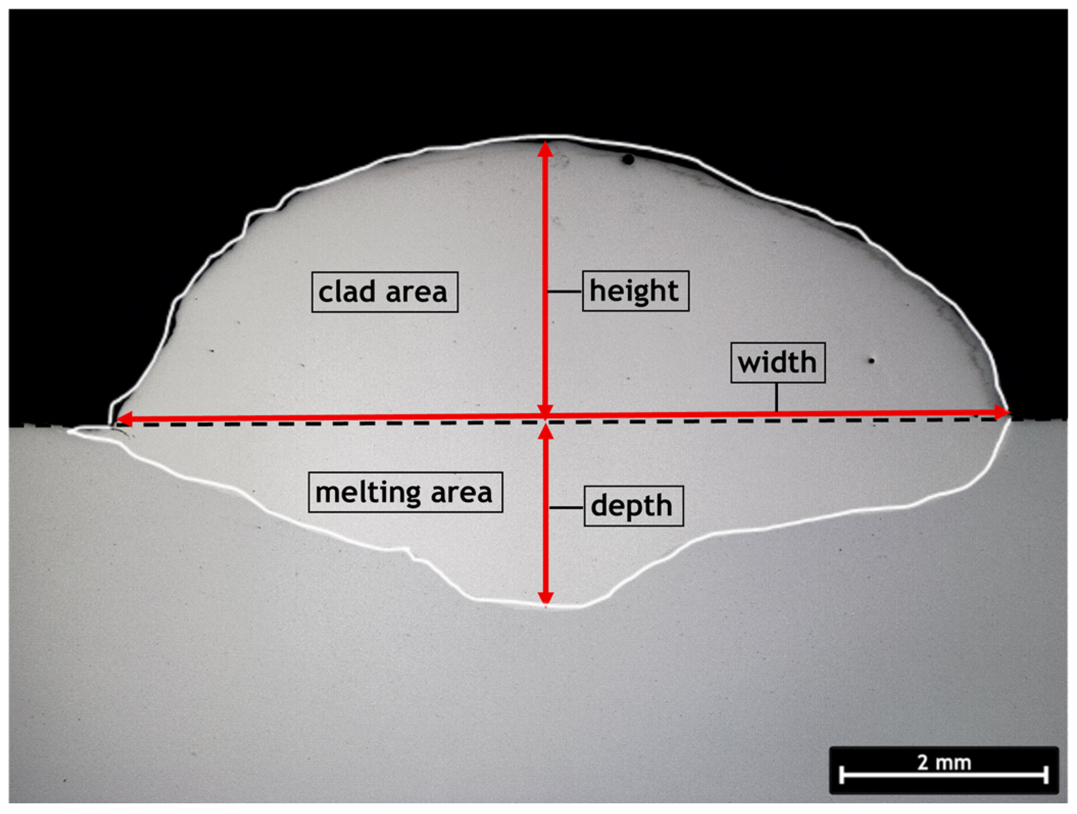
A first screening of all clads was performed by digital microscopy, using a DVM6 Digital Microscope (Leica Microsistemas Lda., Lisbon, Portugal) to assess geometry, dilution and defects. For each clad, the following geometric quantities were measured (
Figure 1): width, height, penetration depth, clad area and melted area. From these, the dilution was calculated by using Equation (1):
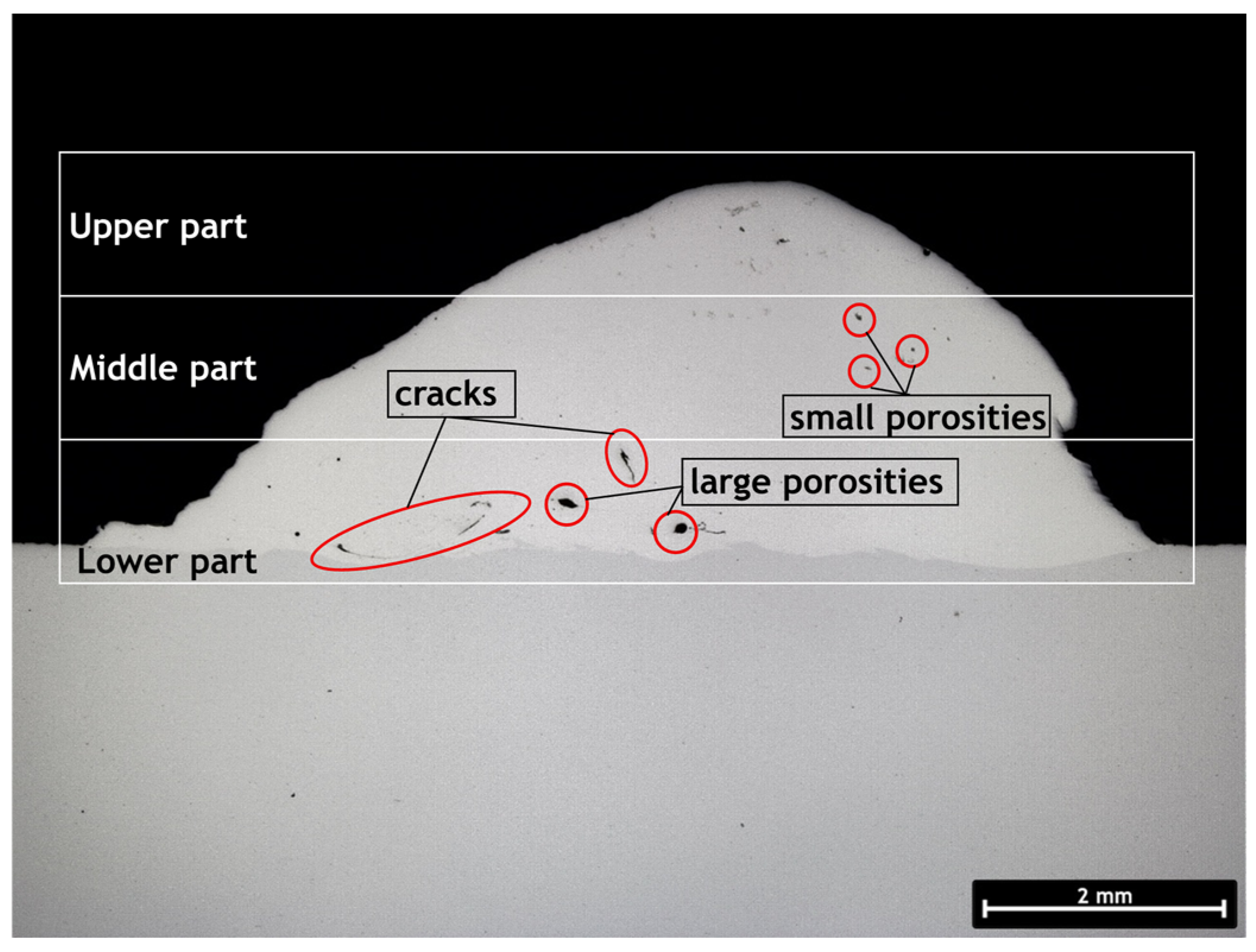
Furthermore, the contact angles at both sides of the bead were measured, and all visible defects were identified and classified as follows: cracks (c), large porosities (lp) and small porosities (sp), with their location in the upper (u), middle (m) or lower (l) regions of the clad indicated (
Figure 2).
To define a set of “high-quality” clads for more detailed microstructural and mechanical characterization, the following selection criteria were applied to the digital microscopy dataset:
Clad area > 25 mm2 (sufficient deposition yield);
Dilution > 14.5% (to ensure adequate metallurgical bonding);
Average contact angle < 90°, with no measured angle exceeding 100° (good wettability and profile);
Absence of cracks and large porosities; small porosities < 150 μm were considered acceptable.
Only clads fulfilling all criteria were selected as representative conditions for each substrate and for subsequent detailed analysis.
2.4. Post-Deposition Heat Treatment
Post-deposition heat treatments were designed to mitigate Laves phase segregation, refine the columnar grain structure, and promote the precipitation of the strengthening γ′ and γ″ phases in Inconel 718 while also alleviating excessive hardness in the heat-affected zone (HAZ) of the S355 substrate. The strategy was inspired by the modified homogenization–aging routes developed for WAAM Inconel 718 and adapted to the available furnace capabilities.
The main heat treatment applied to the WLAM Inconel 718 block consisted of the following:
This plan was selected to keep the temperature safely above the Laves phase dissolution threshold (≈1185 °C) for homogenization, while maintaining a standard double aging cycle.
2.5. Microstructural Characterization (OM, SEM/EDS, EBSD)
Macro- and microstructural observations were first performed by digital and optical microscopy. Digital microscopy was used to quantify clad geometry, dilution and defects, while optical microscopy provided an overview of the cladding layer (CL), fusion line (FL) and heat-affected zone (HAZ), following the same general approach reported for DLD and WAAM clads.
For higher magnification and phase-level analysis, scanning electron microscopy (SEM), energy-dispersive spectroscopy (EDS) and electron backscatter diffraction (EBSD) were employed. SEM/EDS was used to examine the morphology of the clad, HAZ and substrate regions; identify inclusions and segregated phases (e.g., Laves-type constituents); and evaluate elemental partitioning across the interface and interdendritic regions.
EBSD was used to assess grain morphology, grain size, crystallographic texture and phase distribution in both as-built and heat-treated conditions. SEM/EDS and EBSD analysis were carried out on a FEI QUANTA 400 FEG (FEI Company, Hillsboro, OR, USA). EBSD analyses were performed in a field-emission SEM equipped with an EDAX Pegasus X4M system. EBSD data were processed using a standard cleaning routine, employing a dilation algorithm with a grain tolerance angle of 15° and a minimum grain size of 10 points to avoid artifacts from misindexed Kikuchi patterns, consistent with procedures adopted in previous work on laser-cladded and additively manufactured alloys.
2.6. Mechanical Characterization (Hardness and Tensile Tests)
Low-force Vickers hardness measurements were performed to characterize the local mechanical response across the clads, HAZ and substrate. Tests were carried out using a 0.3 kgf load (HV 0.3) and a dwell time of 15 s. Indentations were placed along line profiles perpendicular to the clad surface at 1 mm intervals, starting at the clad and extending through the HAZ into the substrate, to map hardness gradients and quantify the effect of heat treatment on both the Inconel 718 layer and the S355 base material. All measurements were conducted using an InnovaTest Falcon 400 Vickers hardness tester (InnovaTest Company, Maastricht, The Netherlands), and individual profiles were averaged for each condition.
To evaluate the bulk mechanical behavior and anisotropy of WLAM Inconel 718, a solid block was deposited using the parameter combination corresponding to sample S [9.6 0.6 4.9 4] identified as optimal for S355 in the single-track study. From this block, tensile specimens were machined at three orientations relative to the build: horizontal (parallel to the clad-layer direction), vertical (parallel to the build direction), and diagonal (inclined at an angle to the build direction). Half of the block was tested in the as-built condition, while the other half was subjected to the homogenization and double aging treatment described in
Section 2.4. The specimen geometry was guided by ASTM E8/E8M-22 [
22] flat tensile specimen proportions and adapted to miniature dimensions (reduced section length L = 4 mm, width = 2 mm, thickness = 1 mm; cross-sectional area A = 2 mm
2). Tensile tests were conducted at room temperature on an Instron 5900 (Instron, Massachusetts, USA) equipped with a 100 kN load cell under displacement control. A constant crosshead displacement rate of 1 mm/s (60 mm/min) was used for all tests; based on the reduced section length (
mm), this corresponds to an initial engineering strain rate of approximately
= 0.25 s
−1 (15 min
−1). Strain fields and elongation were measured using two-dimensional digital image correlation (DIC) with VIC-2D software version 7.2.68, enabling accurate determination of yield strength (R
p0.2), ultimate tensile strength (R
m), and total elongation at fracture.
3. Results and Discussion
3.1. Digital Microscopy Analysis
The geometrical characteristics of the deposited beads were initially examined using digital microscopy. Quantitative criteria were subsequently applied to assess deposit quality and to identify deposits that met the required acceptance criteria.
Table 4 and
Table 5 summarize, for each bead, the measured parameters, including bead width, height, penetration depth, bead cross-sectional area, fused area, dilution percentage, average wetting angle, and the defects observed.
In this work, sp denotes the substrate; lp(l) refers to the deposition bead corresponding to the lower layer; lp(u) designates the deposition bead corresponding to the upper layer; c(l) indicates the coating applied on the lower bead. The notation lp(l)/sp corresponds to a lower bead deposited directly on the substrate, lp(u)/sp refers to an upper bead deposited directly on the substrate, and c(l)/lp(l)/sp designates a lower coating deposited on the lower bead over the substrate.
The criteria adopted to approve a deposited bead were as follows: a bead cross-sectional area greater than 25 mm2 (ensuring a high material deposition rate); dilution higher than 14.5% (ensuring proper metallurgical bonding with the substrate); an average wetting angle lower than 90° and no local wetting angle exceeding 100° (indicating adequate wetting behavior); and the absence of macroscopic defects (only porosities smaller than 150 µm were tolerated; any crack or porosity larger than this threshold led to bead rejection).
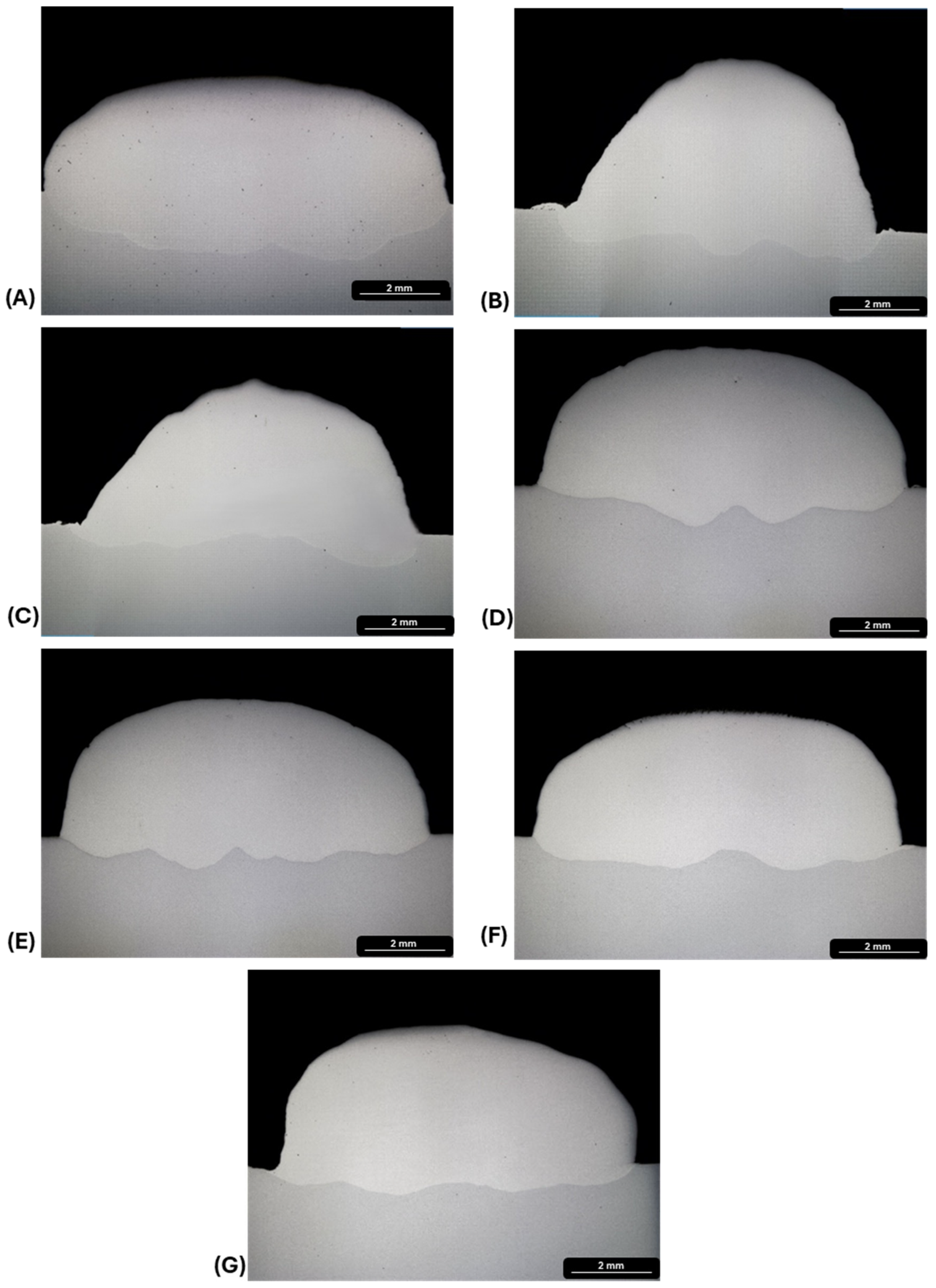
As a result of applying these criteria, seven samples fulfilled all the requirements: three deposited on AISI 304L stainless steel substrates—SS [8.5 0.5 4 4] (plate 1, bead 1), SS [8.5 0.55 5 2] (plate 1, bead 8), and SS [8.5 0.55 5 2] (plate 1, bead 9)—and four deposited on S355 structural steel substrates—S [8.75 0.55 4.5 4] (plate 5, bead 1), S [8.75 0.55 4.5 4] (plate 5, bead 2), S [9.6 0.6 4.75 4] (plate 5, bead 9), and S [9.6 0.6 4.9 4] (plate 6, bead 5). These representative samples are illustrated in
Figure 3.
Both laser speeds evaluated (0.5 and 0.55 m/min) were suitable for 304L, whereas higher speeds resulted in defects. Wire feed rates of 4–5 m/min also yielded satisfactory deposits, and argon pressures of 2 or 4 bar were effective; 3 bar was unsuccessful, primarily due to the excessive laser speed used in that condition. While SS [8.5 0.5 4 4] produced one acceptable bead, another bead deposited under identical parameters failed to meet the wetting and defect-free criteria, indicating limited repeatability. In contrast, the SS [8.5 0.55 5 2] parameter set consistently produced defect-free beads, demonstrating greater robustness. Accordingly, the optimal parameters for depositing Inconel 718 on 304L stainless steel are approximately as follows: 8.5 kW laser power, 0.55 m/min laser speed, 5 m/min wire feed rate, and 2 bar argon pressure.
For beads deposited on S355 structural steel, two parameter ranges yielded the best results: 8.75 kW/0.55 m/min/4.5 m/min/4 bar and 9.6 kW/0.6 m/min/4.75–4.9 m/min/4 bar. Unlike the behaviour observed for 304L, both 8.75 and 9.6 kW produced beads that met the S355 acceptance criteria. Both laser speeds tested (0.55 and 0.6 m/min) were suitable, with the higher speed used with the higher laser power. Wire feed rates of 4.5, 4.75, and 4.9 m/min yielded satisfactory deposits, with higher feed rates corresponding to higher laser power. An argon pressure of 4 bar was common to all approved beads; conditions tested at 3 bar did not meet the acceptance criteria, although only one condition was evaluated.
Repeatability analysis showed a success rate of approximately 50% for both the 8.75 kW/0.55 m/min/4.5 m/min/4 bar and the 9.6 kW/0.6 m/min/4.9 m/min/4 bar parameter sets. In contrast, the 9.6 kW/0.6 m/min/4.75 m/min/4 bar condition resulted in 100% approval, although it was tested only once. This suggests that a slightly lower wire feed rate may be optimal at 9.6 kW, though additional experiments are required to confirm reproducibility. Based on these results, the recommended parameters for depositing Inconel 718 on S355 structural steel are 9.6 kW laser power, 0.6 m/min laser speed, 4.9 m/min wire feed rate, and 4 bar argon shielding gas.
The deposition parameters associated with the approved samples were analyzed to identify process trends. For beads deposited on 304L stainless steel, all approved conditions were produced at a laser power of 8.5 kW, with minor variations in laser speed and wire feed rate. The best results corresponded to SS [8.5 0.5 4 4] (plate 1, bead 1) and SS [8.5 0.55 5 2] (plate 1, beads 8 and 9), deposited at 8.5 kW with laser speeds of 0.5–0.55 m/min, wire feed rates of 4–5 m/min, and argon pressures of 2–4 bar. All beads produced at higher power (9 kW) failed to meet the acceptance criteria, indicating that a laser power of approximately 8.5 kW is optimal for deposition on 304L.
3.2. SEM/EDS and EBSD Analysis
Detailed microstructural analyses of the Inconel 718 deposits were carried out using Scanning Electron Microscopy (SEM) with backscattered electron detection (BSE mode, providing atomic number contrast—Z-contrast), Energy-Dispersive X-ray Spectroscopy (EDS) for local chemical composition assessment, and Electron Backscatter Diffraction (EBSD) for crystallographic orientation determination. Seven deposition conditions were investigated, covering beads deposited on AISI 304L stainless steel and on S355 structural steel substrates, including one sample subjected to post-deposition heat treatment. The results are organized below into thematic sections, with discussions on grain morphology, crystallographic orientation, chemical composition profiles (dilution and segregation), presence of interdendritic phases (such as Laves phases), substrate influence, effects of heat treatment, and observation of non-metallic inclusions.
3.2.1. Columnar Microstructure of Deposited Layers
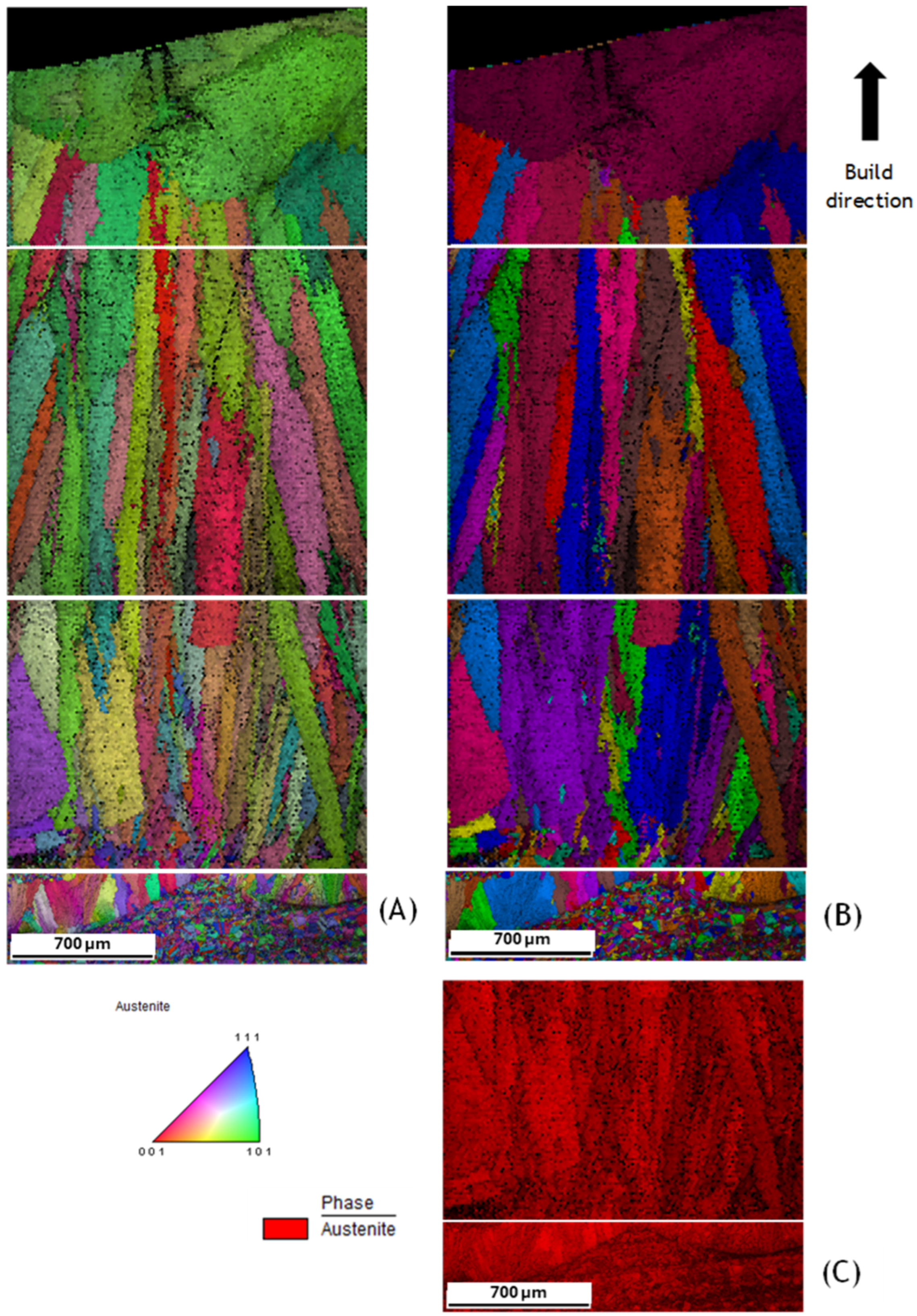
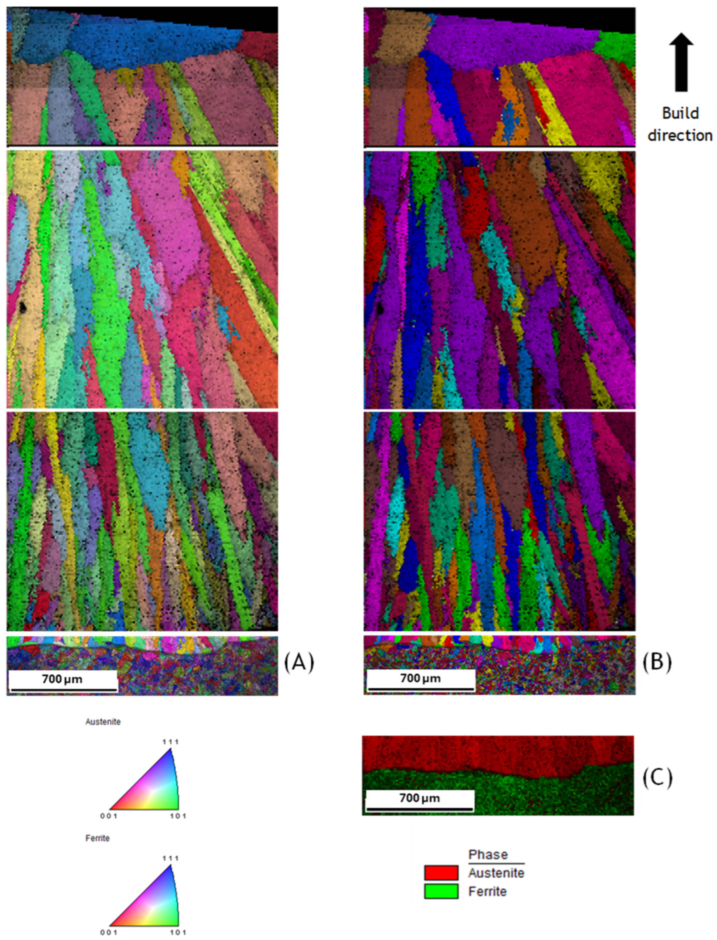
The grain morphology in the Inconel 718 deposits, as observed in the SEM images and EBSD maps of the analyzed samples (
Figure 4 and
Figure 5), is predominantly columnar, with crystalline columns extending over several millimeters along the build direction.
The columnar grains are oriented approximately parallel to the direction of deposit growth, initiating at the substrate–deposit interface and propagating toward the top surface of the deposited layer. Near the substrate–deposit interface, the grains are more elongated and thinner, indicating a pronounced thermal gradient and directional solidification imposed by rapid heat extraction from the colder steel substrate. As solidification progresses toward the top of the bead, the grain width increases significantly. This grain coarsening in the upper regions is consistent with the reduction in thermal gradient and the lower cooling rates near the deposit’s free surface.
This microstructural evolution—fine columnar grains at the base that become progressively thicker toward the top—is typical of Inconel 718 fabricated by wire–laser additive manufacturing (WLAM). The solidification front tends to follow the isotherms defined by the heat source and the substrate geometry, resulting in epitaxial solidification from the substrate. As reported in the literature [
17], the formation of large columnar grains is promoted by epitaxial growth of the initial crystals nucleated on the substrate (or on the previously deposited layer), a mechanism favoured by the requirement of only small nucleation undercooling due to the high thermal conductivity of the steel substrate. Additionally, competitive grain growth aligned with the direction of the maximum thermal gradient suppresses equiaxed grain nucleation, favouring a columnar structure throughout the deposit. The thermal conditions imposed by the WLAM process (a high gradient near the substrate and a lower gradient at the top) explain the hierarchy of grain sizes observed along the height of the deposited beads.
3.2.2. Crystallographic Orientation and Texture
To assess crystallographic orientation and texture development, Inverse Pole Figure (IPF) maps were generated from EBSD scans for each condition. Despite the pronounced presence of columnar grains in the microstructure, the IPF maps shown in
Figure 4 and
Figure 5 did not reveal a strong preferential orientation along the build direction. In other words, no dominant crystallographic texture was detected in the as-fabricated deposits: the grain orientations appear relatively random within the columnar structure.
The absence of a pronounced crystallographic texture in the deposits can be attributed to several factors related to the layer-by-layer deposition process. First, in laser additive manufacturing of Inconel 718, the solidification direction tends to follow the heat flow, which is mainly upward (and slightly lateral) from the substrate. However, successive thermal cycles within each layer and occasional localized remelting between layers can interrupt or redirect epitaxial growth from one layer to the next. As a result, misalignments in grain orientations occur along the deposit height, suppressing the development of a coherent global texture. Thus, even though the grains are macroscopically elongated and aligned, at the crystallographic level the deposits exhibit a broad orientation distribution, with no single crystallographic axis preferentially aligned with the growth direction.
3.2.3. Effect of Heat Treatment on Microstructure
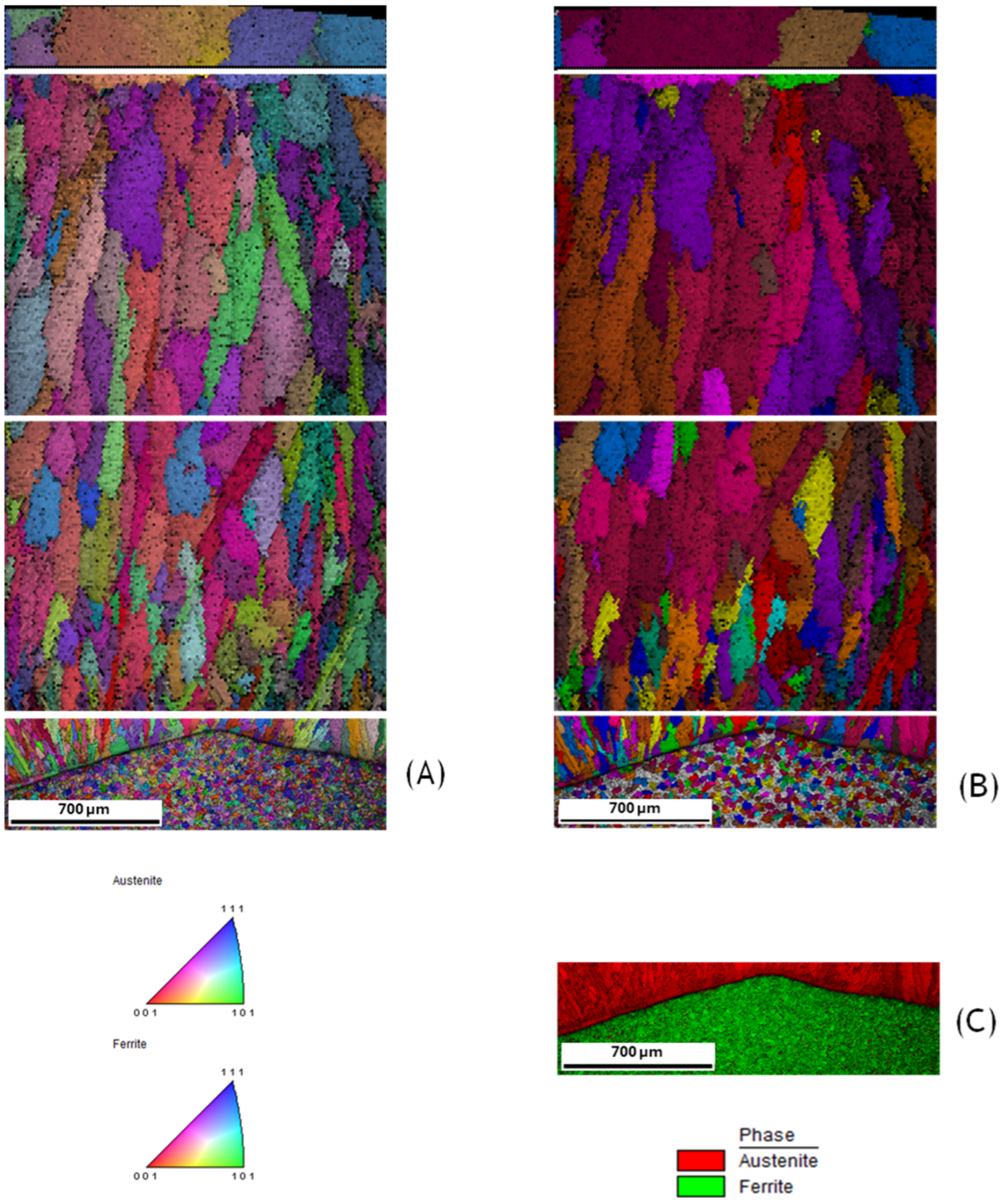
One of the samples deposited on the S355 steel substrate (S [9.6 0.6 4.9 4], plate 6, bead 5) was subjected to a solution heat treatment followed by aging, with the aim of evaluating post-processing microstructural changes. After heat treatment, the microstructure exhibited significant modifications: the previously columnar grains became noticeably smaller and more equiaxed, as evidenced by the EBSD map in
Figure 6.
This grain refinement and rounding increase microstructural isotropy and reduce the intensity of any remaining crystallographic texture, thereby improving mechanical properties. In Inconel 718 alloys, such microstructural evolution generally results in higher toughness and improved fatigue resistance, as an equiaxed microstructure reduces stress concentrations and undesirable anisotropy. Moreover, during the solution treatment stage, brittle segregated phases, such as interdendritic Laves phases, dissolve, releasing elements such as Nb back into the matrix. Subsequently, the aging treatment promotes uniform precipitation of the strengthening phases (γ′/γ′′) within the refined grain matrix. These mechanisms—partial recrystallisation with equiaxed grain formation and dissolution of brittle phases, followed by controlled precipitation of hardening phases—account for the substantial improvement in the properties of heat-treated Inconel 718 compared with the as-deposited condition.
3.2.4. Dilution at the Interface and Chemical Composition Profiles
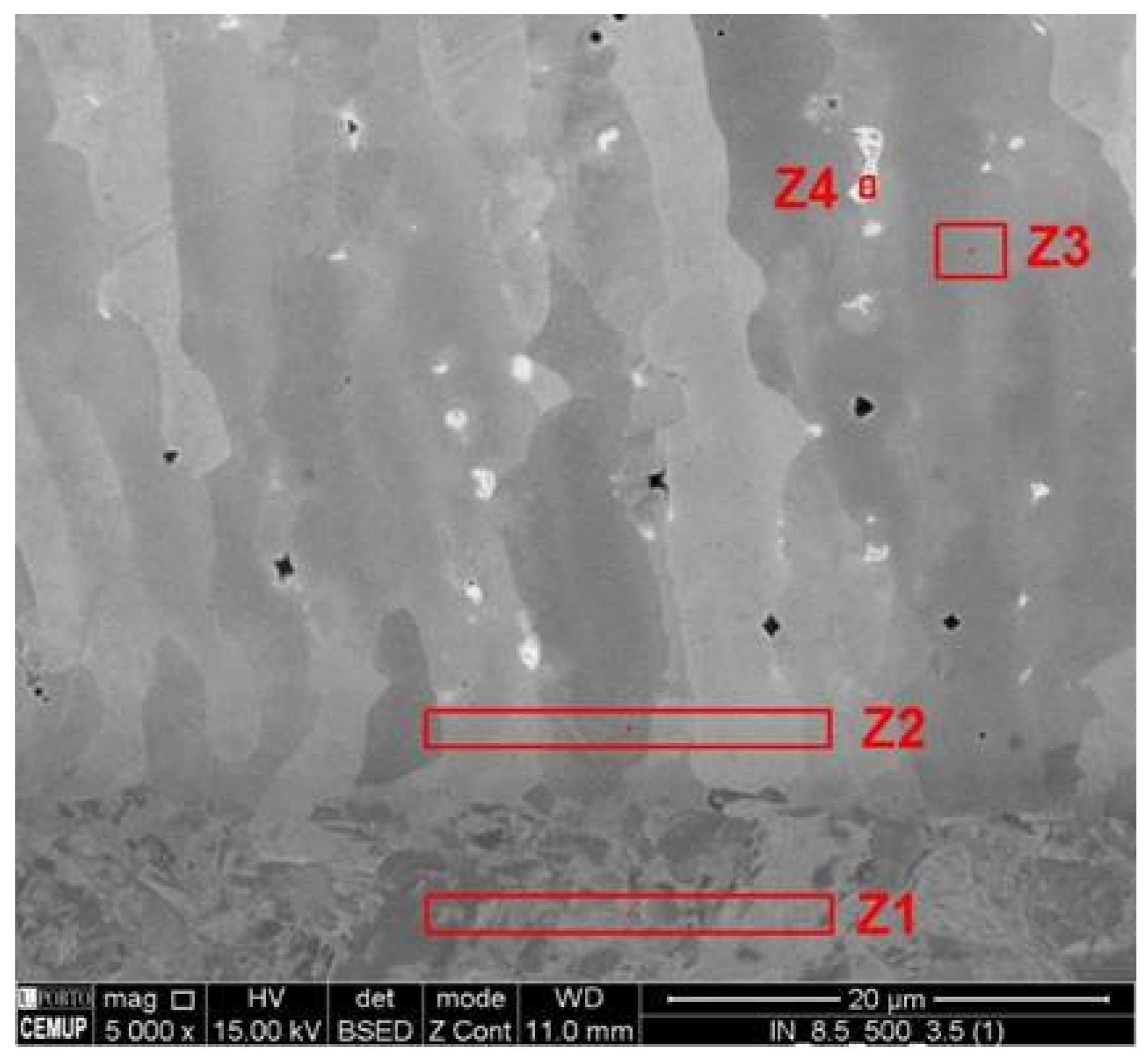
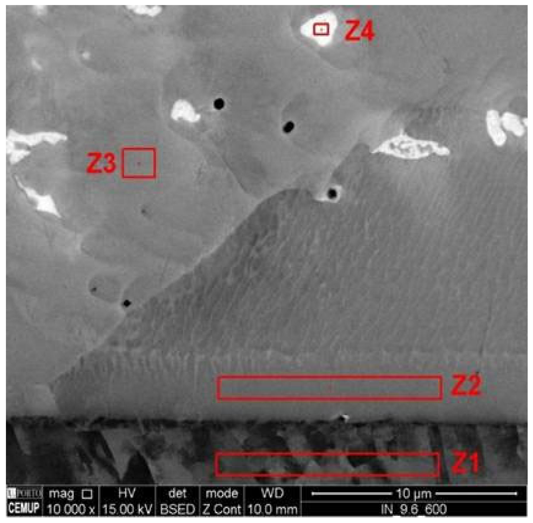
To investigate the influence of the substrate material on dilution behavior, elemental segregation, and microstructural development of Inconel 718 WLAM beads, two representative conditions were analyzed in detail: one sample deposited on AISI 304L stainless steel (SS [8.5 0.5 4 4], plate 1, bead 1) and another deposited on S355 structural steel (S [9.6 0.6 4.9 4], plate 6, bead 5). SEM imaging in BSE mode and EDS microanalyses were performed in four distinct zones along the transverse cross-section of each sample—ranging from the substrate/deposit interface to the upper region of the bead—as illustrated in the micrographs in
Figure 7 and
Figure 8. The chemical compositions measured in each zone (Z1, Z2, Z3, and Z4) are presented in
Table 6 and
Table 7.
The identification of these zones enables quantification of the degree of substrate dilution in the deposit, highlighting alloying element segregation, and allows us to understand the metallurgical transition between the substrate and the deposited metal in each case.
For the deposit on the 304L substrate, as shown in
Figure 7, the region immediately adjacent to the interface (zone Z1, substrate dilution zone) exhibited a chemical composition typical of AISI 304L stainless steel, with high Fe and Cr contents and low Ni content. As the EDS analysis progresses into the bead (zones Z2 and Z3, progressively farther from the interface), a gradual increase in nickel (Ni) content is observed—from about 8.6 wt.% in Z1 to approximately 30.0 wt.% in Z2, reaching 36.96 wt.% in Z3—while iron (Fe) concomitantly decreases (from ≈72.1 wt.% in Z1 to 47.0 wt.% in Z2 and 39.66 wt.% in Z3). This progressive compositional shift indicates a smooth transition from the stainless steel substrate composition to the deposited Inconel 718 matrix. In the last analyzed region of the bead, Z4, the chemical composition changes more markedly: Ni stabilizes around 32.7 wt.% and Fe drops to ≈19.6 wt.%, while substantial enrichment in niobium (Nb, ≈27.8 wt.%) and other segregating elements (e.g., Mo and Ti, at elevated levels) occurs. The composition of zone Z4 is consistent with the formation of an Nb-rich Laves phase, identified as a bright interdendritic phase in the BSE image. This Laves phase—a brittle interdendritic constituent commonly observed in deposited superalloys—results from the accumulation of Nb and other segregating elements in the last portions to solidify. Its excessive presence is undesirable, as this phase is hard and brittle and can degrade material ductility if not eliminated by subsequent heat treatment.
In the sample deposited on S355 steel (
Figure 8), a more abrupt compositional gradient between the substrate and the deposit was observed. In the substrate region Z1 (slightly below the interface), Fe reached ≈97.84 wt.%, with negligible contents of Inconel alloying elements—clearly indicating minimal dilution of the filler metal at this depth. In the transition zone Z2, immediately above the interface, a pronounced change occurred: the Fe content decreased to approximately 52.95 wt.%, whereas Ni increased to approximately 32.58 wt.%. This sharp variation indicates the formation of a mixed fusion zone at the interface, where partial mixing between the substrate and the deposited material occurred. Above this region, within the bead interior (zone Z3), Ni continued to increase (38.44 wt.%) and Fe to decrease (43.38 wt.%), approaching more closely the nominal composition of Inconel 718. Finally, the interdendritic zone at the top of the bead (Z4) exhibited extreme Nb segregation, reaching ≈58.8 wt.%, while Fe and Ni both decreased to around 15 wt.%. This single Z4 composition confirms the presence of a strongly segregated Laves phase, analogous to that observed in the 304L case but even more enriched in Nb. The bright contrast in the BSE images of these areas (due to the high atomic number of concentrated Nb) supports the interpretation of Nb-rich interdendritic precipitates—typical of the Laves phase formed during solidification of as-deposited Inconel 718.
Comparing the two substrate systems, it is evident that the deposit on AISI 304L stainless steel exhibited a more gradual dilution gradient, partly due to the greater chemical and thermal similarity between 304L and Inconel 718. Mutual dissolution between the deposit and the substrate occurred more homogeneously, resulting in smoother compositional transitions and less intense elemental segregation. In contrast, the carbon steel S355 substrate—owing to its ferritic–pearlitic microstructure and lower thermal conductivity—promoted more abrupt metallurgical transitions. In this case, less efficient heat extraction and greater metallurgical mismatch led to more discontinuous solidification at the interface, increasing interdendritic segregation and favouring the formation of larger fractions of brittle Laves phase in the deposit. These results clearly demonstrate the strong influence of substrate material on the final microstructure obtained by laser deposition: substrates that reduce the thermal gradient or introduce incompatible diluting elements tend to exacerbate segregation and the formation of undesirable phases.
3.2.5. Observed Non-Metallic Inclusions
In addition to metallic phases, EDS analysis revealed non-metallic inclusions in the deposits, possibly originating from the feedstock powder or from reactions during melting. In particular, particles containing oxides and complex Nb/Ti carbonitrides were identified.
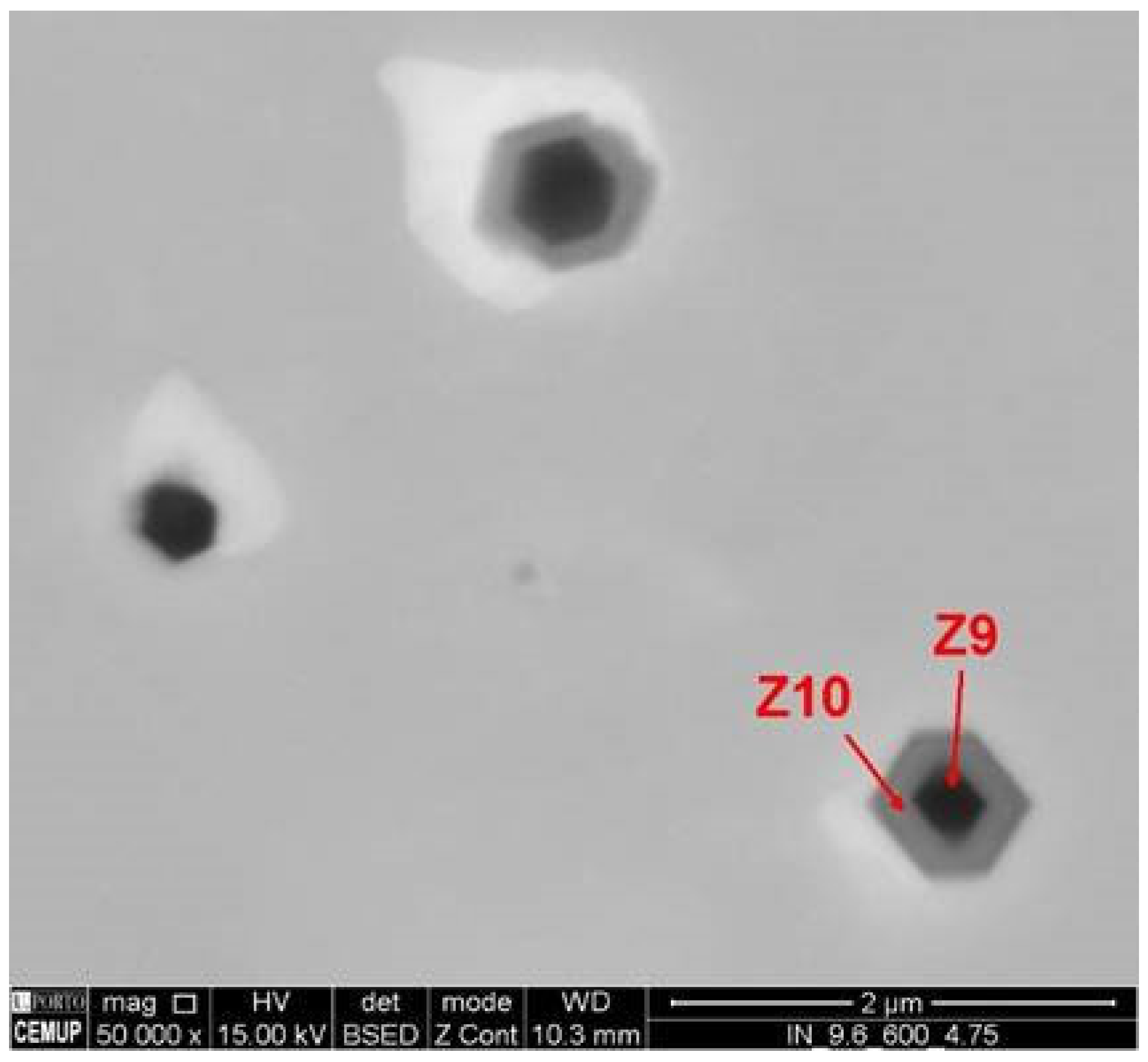
Figure 9 illustrates a typical inclusion observed in the deposit (sample S [9.6 0.6 4.75 4], plate 5, bead 9), showing an oxide core surrounded by carbonitride precipitates.
The detailed chemical composition of two regions—the inclusion core (zone Z9) and its peripheral layer (zone Z10)—is presented in
Table 8.
It is observed that the core consists predominantly of a MgO·Al2O3 spinel (magnesium–aluminum oxide), while the surrounding layer is rich in niobium and titanium carbonitrides ((Nb, Ti) CN). In other words, the inclusion exhibits an internal oxide phase (MgO·Al2O3) surrounded by Nb/Ti carbonitride precipitates. The formation of these composite inclusions indicates oxidation and nitridation reactions during the process: high-temperature oxides (MgO·Al2O3) likely acted as nucleation sites for the subsequent precipitation of Nb and Ti carbonitrides during solidification. Although the fraction of these inclusions is low, their presence may locally affect properties by serving as potential crack initiation sites or by reducing in-service toughness. Detailed characterization of these inclusions is therefore important to assess the cleanliness of the deposited metal and to guide process improvements (e.g., feedstock wire quality or shielding gas protection) aimed at minimizing oxide incorporation.
3.2.6. Interdendritic Segregation and Laves Phase
The Laves phase, identified in the interdendritic regions of the deposits, deserves special attention due to its impact on the microstructure and the alloy’s properties. In nickel-based superalloys produced by additive manufacturing (such as Inconel 718 in the as-deposited condition), segregation of Laves-forming elements—most notably niobium (Nb), but also molybdenum (Mo) and titanium (Ti)—commonly occurs during solidification. These segregating elements are rejected from the growing dendrite cores and accumulate in the end regions for solidification, enriching the residual liquid in solute. As a result, the Laves phase precipitates in these interdendritic regions or along dendritic cell boundaries, forming brittle eutectic constituents at grain boundaries.
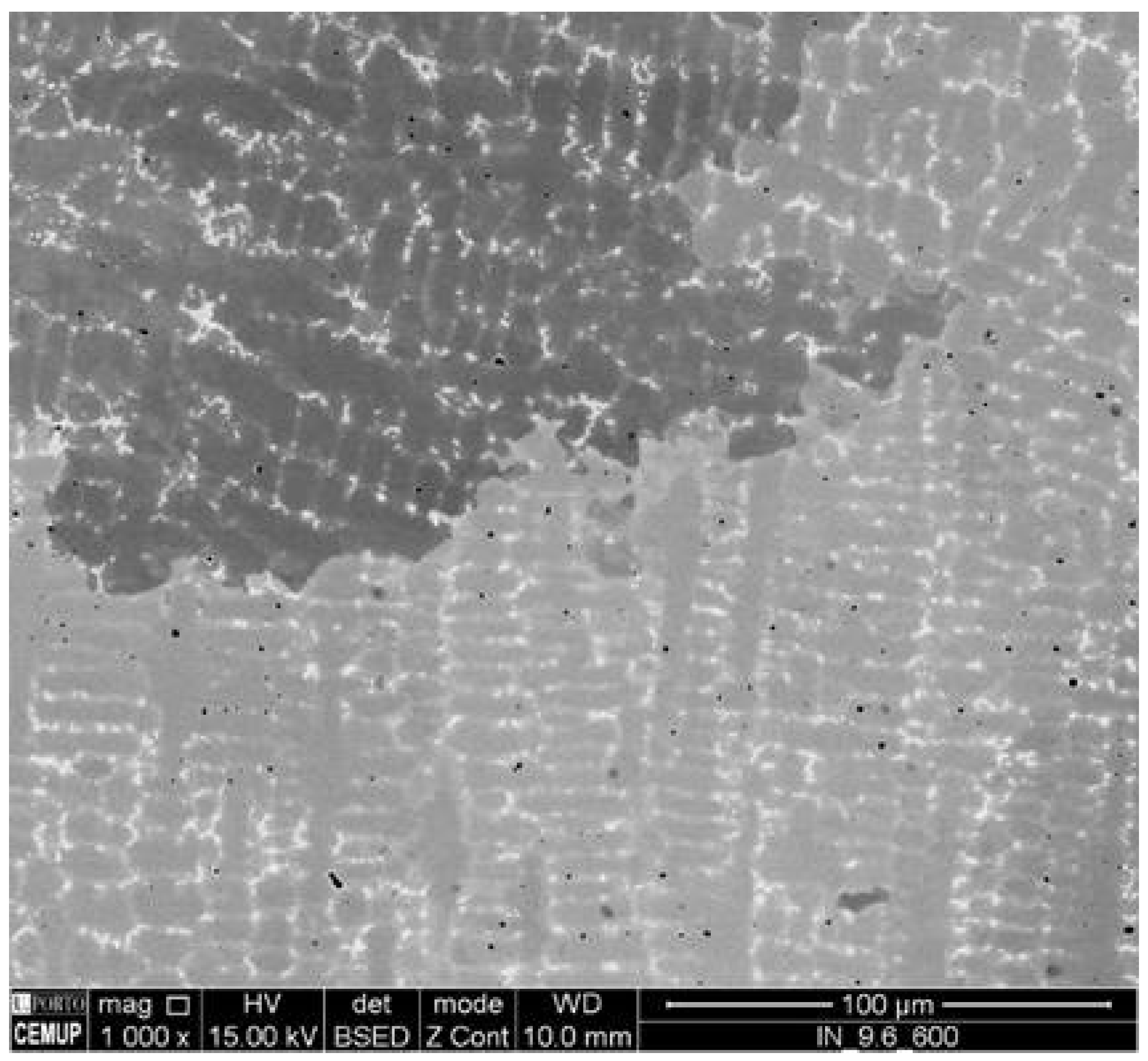
Figure 10 illustrates the typical distribution of the Laves phase along interdendritic regions in one of the deposits (sample S [9.6 0.6 4.9 4], plate 6, bead 5), where bright particles aligned with dendritic boundaries—corresponding to the Nb-rich phase—are observed.
This pronounced interdendritic segregation is inherent to the non-equilibrium solidification characteristic of the WLAM process and explains the high Nb contents measured by EDS in zones Z4. Although the presence of the Laves phase is virtually unavoidable in the as-deposited material, its control is essential: post-processing heat treatments (solution treatments) are intended to dissolve the Laves phase back into the matrix, redistributing elements such as Nb more uniformly, thereby enabling the formation of the desired strengthening phases (γ′/γ″) during subsequent aging. If the Laves phase remains in excess in the final microstructure, it will act as a source of embrittlement, reducing the component’s ductility and fatigue resistance. Therefore, understanding interdendritic segregation and the dissolution kinetics of the Laves phase is crucial for optimizing both the deposition process parameters (minimizing extreme thermal gradients and off-target compositions) and the subsequent heat treatment schedules, ensuring a refined and well-balanced microstructure suitable for high-temperature service.
3.3. Hardness Results
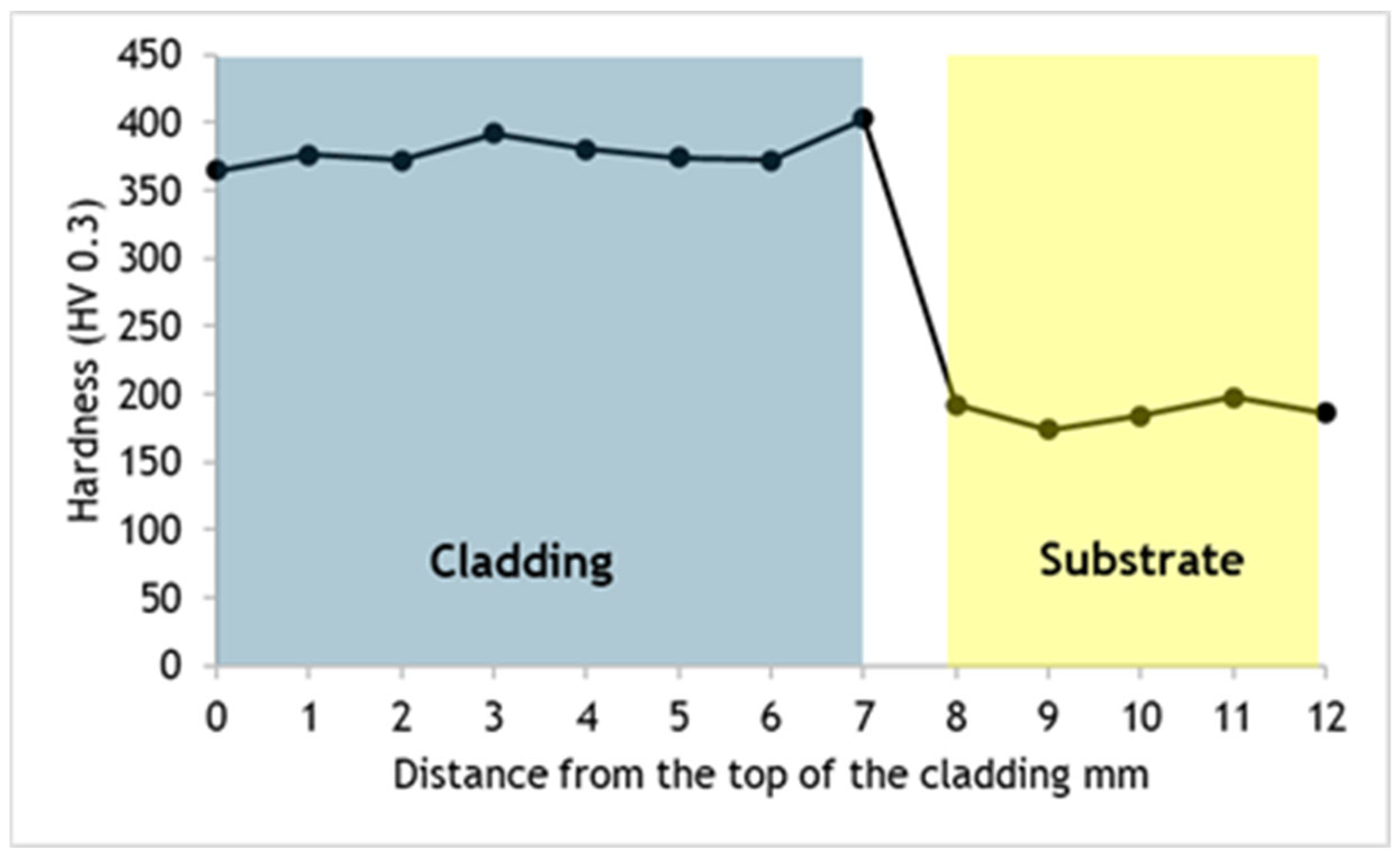
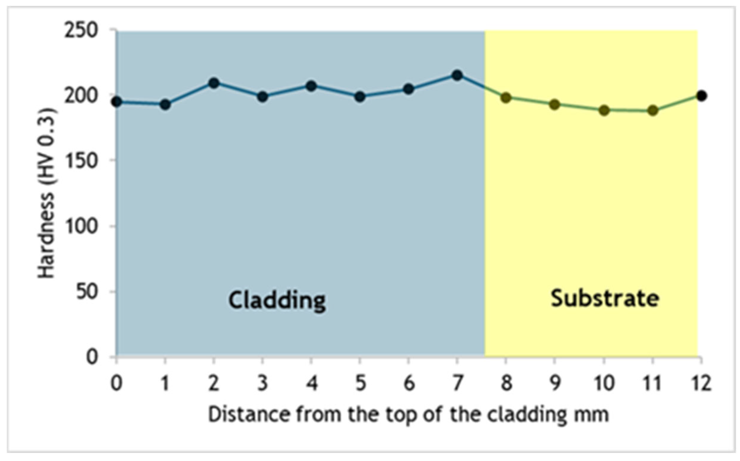
The microhardness results were used to assess the influence of substrate material, deposition conditions, and post-deposition heat treatments on the mechanical response of the deposited claddings. Clear differences were observed between deposits produced on austenitic stainless steel SS304L and those produced on ferritic–pearlitic structural steel S355, as well as between the as-deposited and heat-treated conditions. The hardness distribution obtained for the cladding deposited on SS304L, sample SS [8.5 0.5 4 4] (plate 1, clad 1), is summarized in
Table 9, while the corresponding hardness profile is shown in
Figure 11.
The cladding exhibited an average hardness of approximately 201 HV 0.3, with limited scatter along the deposited layer. The SS304L substrate exhibited an average hardness of 192 HV 0.3, with no discernible gradients. No hardness variation was detected across the heat-affected zone (HAZ), indicating that the thermal cycle imposed during deposition was insufficient to induce significant microstructural changes. This behaviour is consistent with the high phase stability of austenitic stainless steels, which are less prone to phase transformations, carbide precipitation, or thermal hardening under localized thermal exposure. A markedly different behaviour was observed for claddings deposited on S355 structural steel. For sample S [9.6 0.6 4.75 4] (plate 5, clad 9), the hardness values are reported in
Table 10, and the hardness profile is presented in
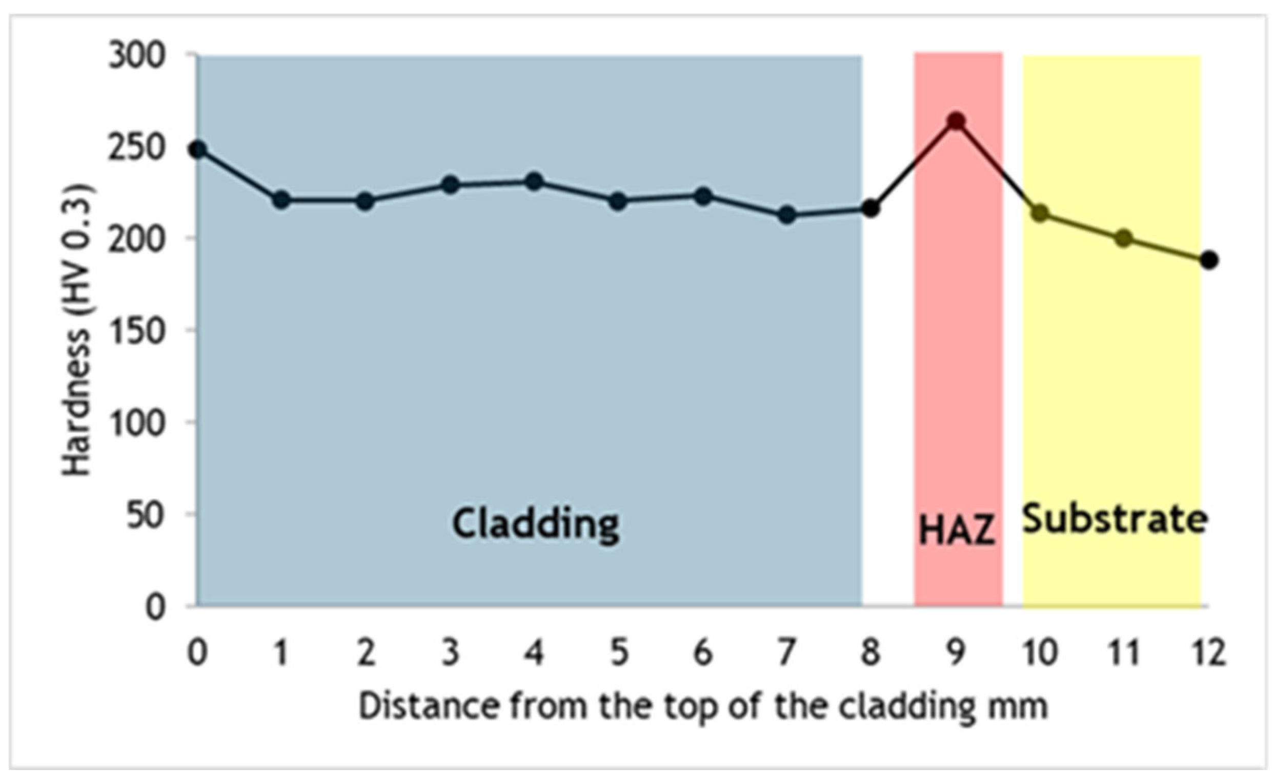
Figure 12.
The cladding exhibited an average hardness of 225 HV 0.3, which remained relatively uniform across the deposited material. In contrast, a pronounced increase in hardness was observed in the HAZ, reaching 264 HV 0.3, corresponding to approximately 63 HV relative to the substrate hardness of 201 HV 0.3. This localized hardening is attributed to the thermal sensitivity of ferritic–pearlitic steels, in which the thermal cycle can promote grain coarsening, carbide redistribution, and the formation of harder microstructures, such as bainite or martensite, depending on the cooling rate. Although a slight decrease was observed in the substrate hardness profile, additional random measurements confirmed that substrate hardness remained consistent, indicating that the hardness peak was effectively confined to the HAZ.
The application of a post-deposition heat treatment significantly modified the hardness response of this system. For sample S [9.6 0.6 4.75 4] (plate 5, clad 9), subjected to a homogenization treatment at 1200 °C for 15 min, followed by double aging at 720 °C for 8 h and 625 °C for 8 h, the results are presented in
Table 11, with the hardness profile shown in
Figure 13.
A substantial increase in cladding hardness was observed, reaching 379 HV 0.3, corresponding to approximately 68% relative to the as-deposited condition. This increase is primarily attributable to precipitation hardening and microstructural refinement induced by the applied heat treatment, which are characteristic of precipitation-hardenable nickel-based alloys such as Inconel 718. In addition, the heat treatment eliminated the previously observed hardened HAZ, indicating the suppression of brittle microstructural features. The substrate hardness slightly decreased to 187 HV 0.3, remaining within the expected range for S355 structural steel. The hardness values obtained for both the cladding and the substrate are consistent with typical values reported for AMS 5596 nickel alloys and with the upper limits commonly accepted for S355 steels.
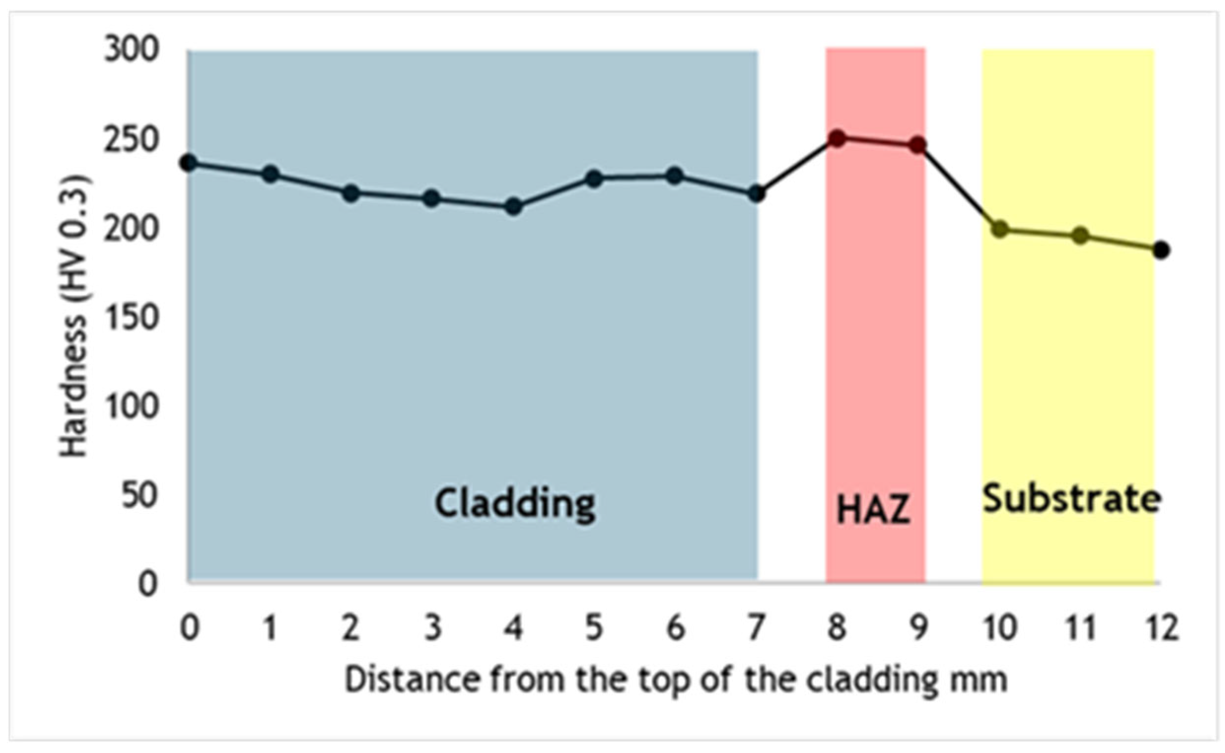
A similar trend was observed for sample S [9.6 0.6 4.9 4] (plate 6, clad 5). In the as-deposited condition, the hardness values reported in
Table 12 and the profile shown in
Figure 14 indicate an average cladding hardness of 224 HV 0.3, while the HAZ reached 248 HV 0.3, corresponding to an increase of approximately 54 HV relative to the substrate hardness of 194 HV 0.3. These results further confirm the susceptibility of the S355 steel to localized hardening in the HAZ due to the deposition thermal cycle.
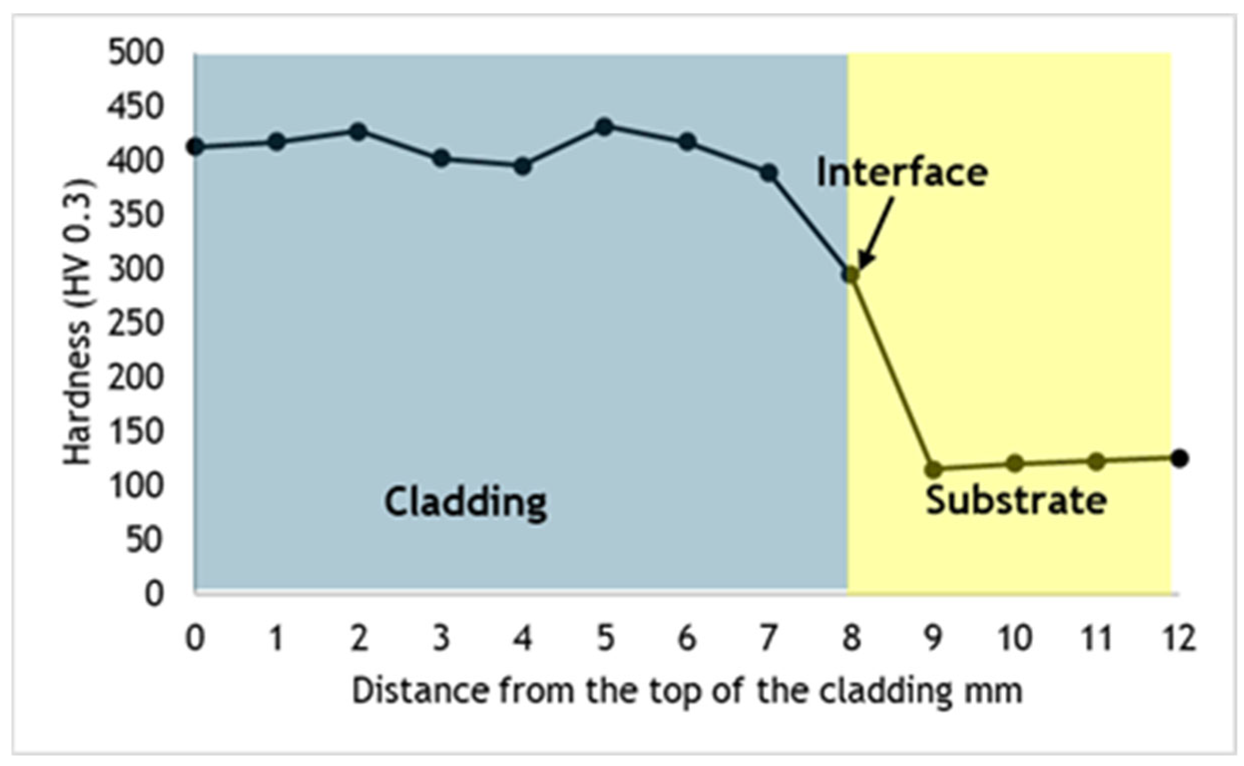
After post-deposition heat treatment, consisting of homogenization at 1200 °C for 10 min, followed by the same double aging sequence, the hardness results are summarized in
Table 13, with the corresponding profile shown in
Figure 15.
The cladding hardness increased to 412 HV 0.3, approximately 84% higher than in the as-deposited condition. The shorter homogenization time appears to have enhanced the precipitation-hardening response during aging. As observed for the previous sample, the hardened HAZ was completely eliminated after heat treatment. Conversely, the substrate exhibited a significant reduction in hardness, reaching 121 HV 0.3, which can be associated with stress relief and microstructural recovery during the thermal cycle.
Overall, the results demonstrate that the hardness distribution in the investigated systems is strongly governed by the substrate’s metallurgical nature and the application of post-deposition heat treatments. While SS304L exhibited high microstructural stability under the imposed thermal cycles, the S355 steel showed a pronounced tendency toward HAZ hardening in the as-deposited condition. Appropriate heat treatments proved effective in simultaneously enhancing the mechanical performance of the claddings through precipitation hardening and mitigating the formation of brittle regions at the interface, highlighting their critical role in ensuring the structural integrity and performance of such coated systems.
3.4. Tensile Test Results
To mechanically characterize the deposited material, tensile specimens were extracted from an Inconel 718 block manufactured using the same processing parameters as bead S [9.6 0.6 4.9 4] (plate 6, coating 5). The block was sectioned into two halves, from which tensile specimens were machined along three different orientations: horizontal, vertical, and diagonal.
One half of the block was tested in the as-deposited condition, while the other half was subjected to the heat treatment described in
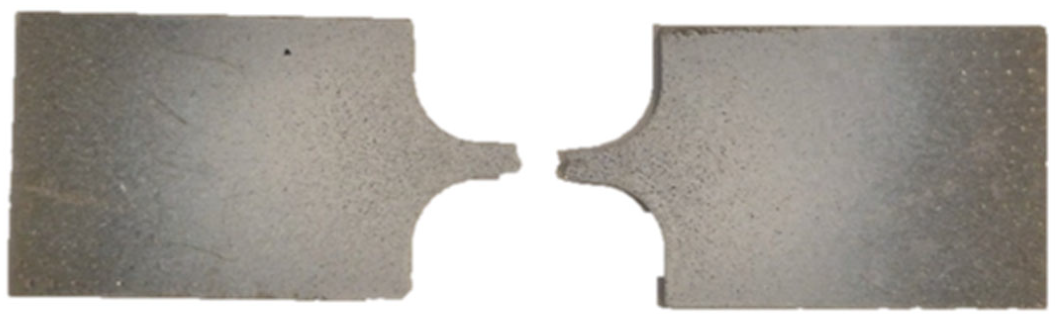
Section 3.3, thereby enabling assessment of the effect of the heat treatment on the material’s mechanical properties. An example of a tensile specimen after fracture is shown in
Figure 16.
3.4.1. Mechanical Properties in the Horizontal Direction
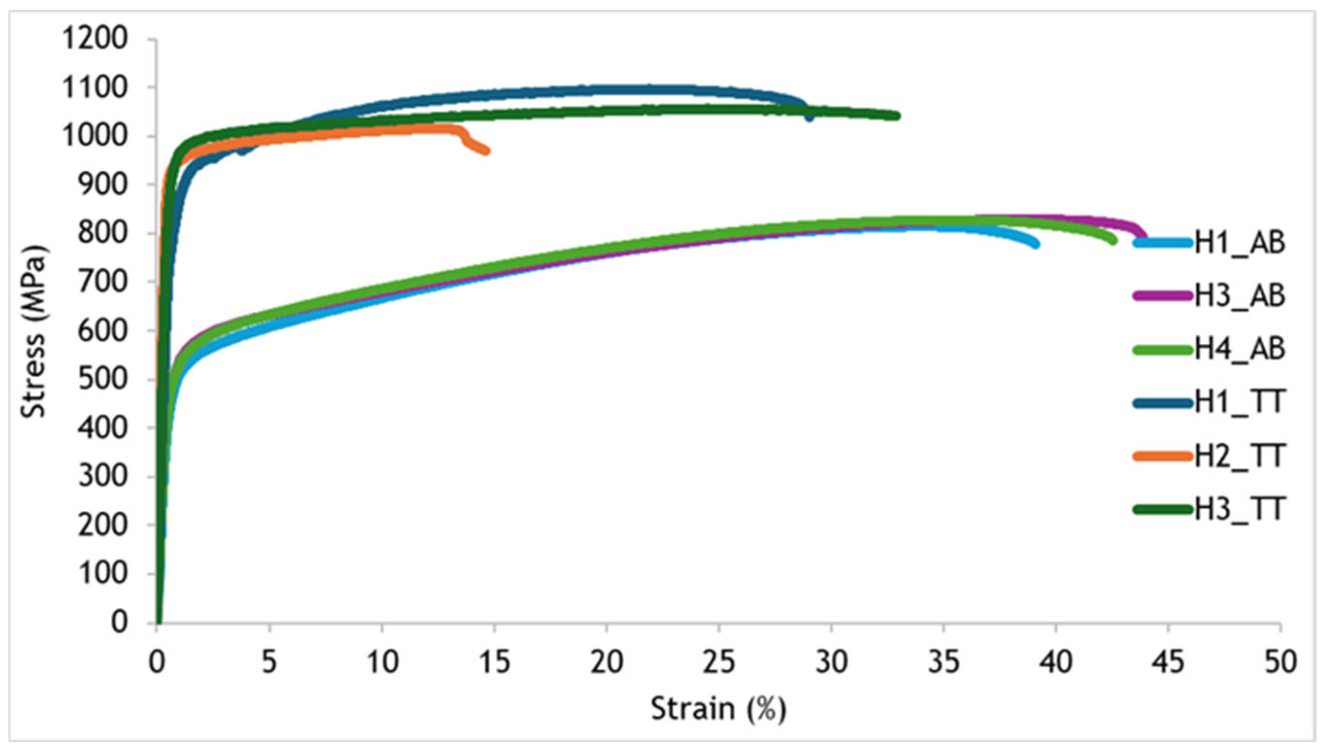
The engineering stress–strain curves corresponding to the horizontally oriented tensile specimens are shown in
Figure 17. The as-deposited specimens exhibited highly uniform mechanical behaviour, with average values of yield strength at 0.2% offset (R
p0.2) of 447 ± 9 MPa, ultimate tensile strength (R
m) of 824 ± 6 MPa, and elongation to failure (A) of 41 ± 2%. These results indicate high ductility combined with relatively low strength, which is consistent with annealed Inconel 718 in accordance with ASTM B637.
After heat treatment, the results showed increased variability, particularly in elongation, primarily due to the presence of critical defects in one specimen (H2_TT). The average mechanical properties were Rp0.2 = 853 ± 66 MPa, Rm = 1057 ± 33 MPa, and A = 25 ± 8%. Compared with the as-deposited condition, this results in a 91% increase in Rp0.2 and a 28% increase in Rm, along with a 39% reduction in elongation. The substantial improvement in strength is primarily attributed to the formation of coherent γ′ and γ″ precipitates during the aging treatment, which act as effective barriers to dislocation motion, leading to precipitation hardening.
3.4.2. Mechanical Properties in the Vertical Direction
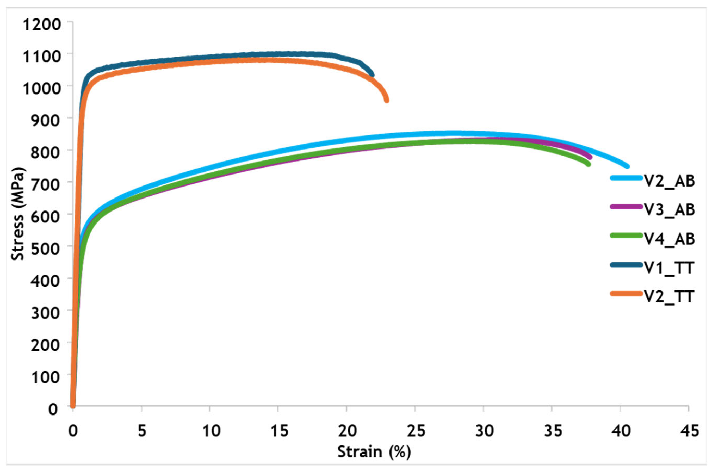
In the vertical direction, the tensile stress–strain curves are presented in
Figure 18. In the as-deposited condition, the specimens exhibited average mechanical properties of R
p0.2 = 488 ± 8 MPa, R
m = 836 ± 10 MPa, and elongation to failure (A) of 38 ± 1%, indicating behaviour similar to that observed in the horizontal direction, characterized by high ductility and relatively low mechanical strength. In this orientation, the alignment of columnar grains along the tensile axis may promote intergranular fracture, thereby reducing the plastic deformation capacity relative to the transverse orientation.
After heat treatment, the mechanical properties increased to Rp0.2 = 960 ± 40 MPa, Rm = 1090 ± 33 MPa, and A = 22 ± 0.5%, corresponding to increases of 97% in Rp0.2 and 30% in Rm, along with a reduction of 42% in elongation. One specimen was excluded from the analysis due to slippage during the tensile test. The observed strengthening confirms the effectiveness of the heat treatment in activating strengthening phases and relieving residual stresses.
3.4.3. Mechanical Properties in the Diagonal Direction
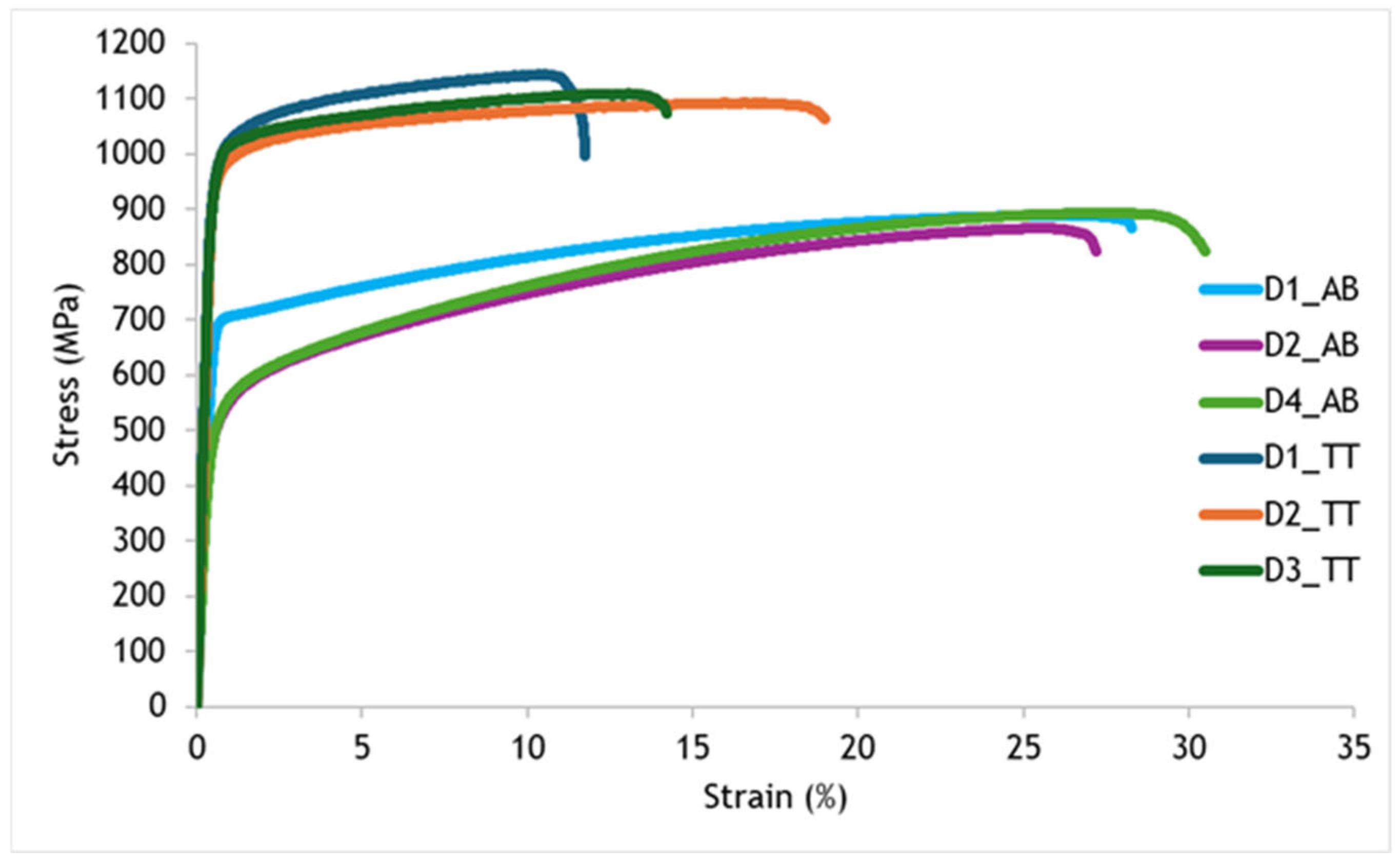
The tensile stress–strain curves corresponding to the diagonal direction are shown in
Figure 19. A pronounced scatter was observed among the as-deposited specimens: one specimen (D1_AB) exhibited a R
p0.2 value of 700 MPa, whereas the remaining samples presented values in the range of 490–510 MPa. This variability may be associated with the specimen extraction location within the block, which affects local cooling conditions, as well as with residual stress heterogeneity in thin sections. The overall average mechanical properties in the as-deposited condition were R
p0.2 = 567 ± 95 MPa, R
m = 883 ± 12 MPa, and elongation to failure (A) of 28 ± 1%.
In the heat-treated condition, Rp0.2 and Rm values were more consistent across the specimens, reaching 957 ± 2 MPa and 1116 ± 22 MPa, respectively, whereas elongation exhibited significant variability, ranging from 10% to 19%, with an average value of 14 ± 3%. Compared to the as-deposited state, this corresponds to an increase of 69% in Rp0.2 and 26% in Rm, along with a reduction of 50% in elongation. The diagonal orientation imposes an oblique loading condition relative to grain boundaries, promoting the simultaneous activation of multiple fracture mechanisms, such as transgranular cleavage and intergranular decohesion, which explains the increased scatter and reduced ductility observed in this direction.
3.4.4. Comparative Summary and Discussion of Mechanical Anisotropy
Table 14 summarizes the average values of yield strength at 0.2% offset (R
p0.2), ultimate tensile strength (R
m), and elongation to failure (A, %) for the three investigated orientations under the as-deposited and heat-treated conditions.
The tensile data presented in
Table 14 clearly indicate the influence of build orientation and heat treatment on the mechanical behaviour of the deposited Inconel 718. In the as-built condition, the horizontal and vertical directions exhibit comparable yield and ultimate tensile strengths, accompanied by high elongation, whereas the diagonal direction presents higher strength levels but reduced ductility. After heat treatment, all orientations exhibit substantial increases in yield and ultimate tensile strengths, accompanied by a marked decrease in elongation. The vertical and diagonal directions exhibit similar yield strengths, whereas the diagonal specimens exhibit the lowest ductility, highlighting the role of loading orientation relative to the columnar grain structure in governing anisotropic mechanical response.
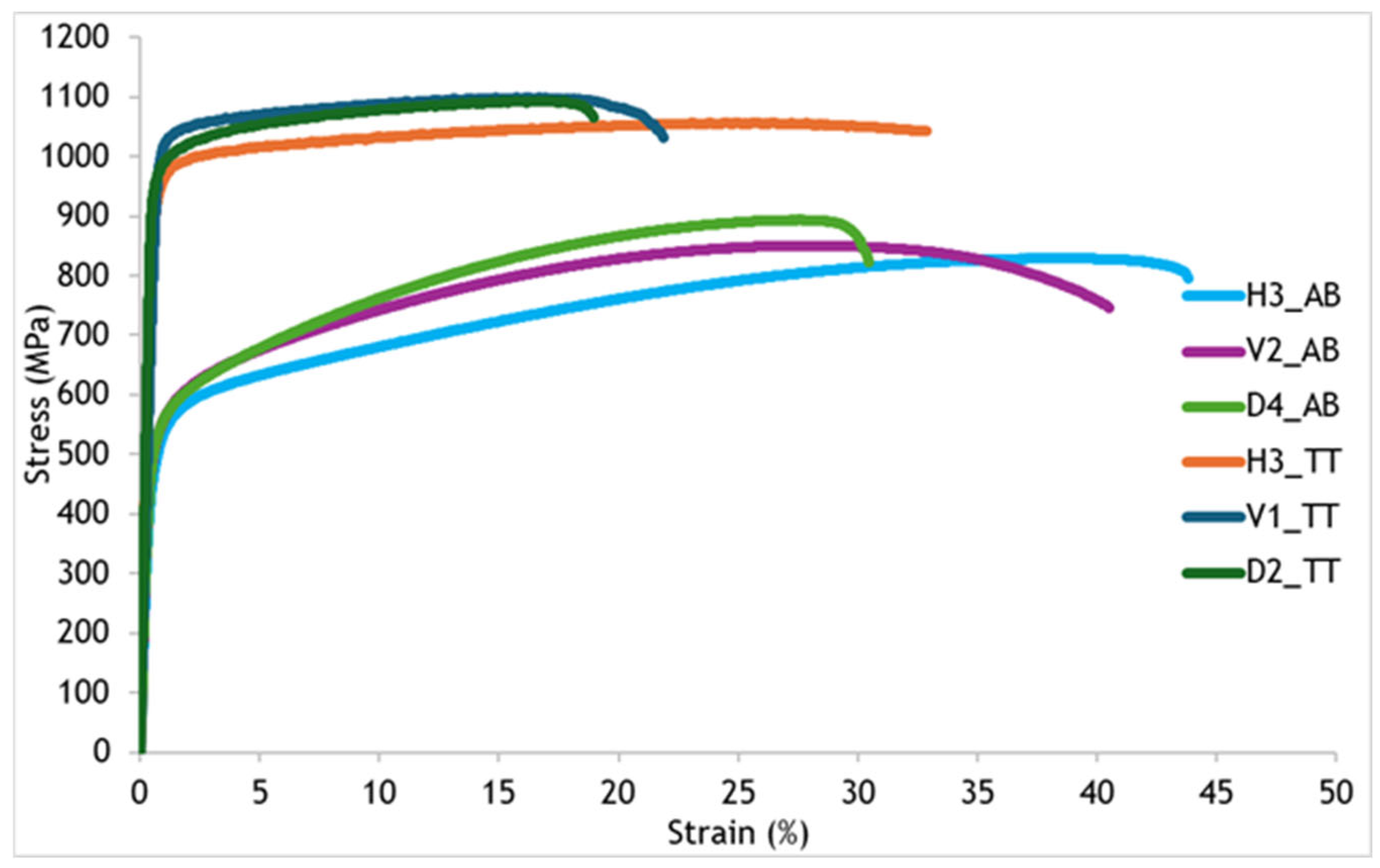
Figure 20 presents representative stress–strain curves for each condition, illustrating the effects of heat treatment and build orientation on the material’s mechanical behavior.
In processes such as WLAM, mechanical anisotropy is expected due to the layer-by-layer deposition strategy, the complex thermal history, and epitaxial columnar grain growth. Specimens extracted horizontally, parallel to the deposited layers, tend to exhibit higher elongation due to facilitated plastic deformation between columnar grains. In the vertical (build) direction, fracture tends to occur more rapidly due to grain alignment with the loading axis, which promotes intergranular cracking. The diagonal direction exhibited the lowest elongation values, likely due to complex interactions between loading orientation and grain morphology, which led to mixed fracture modes (intergranular and transgranular), as illustrated by the representative stress–strain curves in
Figure 20.
These observations confirm that the extraction direction directly affects the final mechanical properties and must be carefully considered in the structural application and qualification of WLAM-fabricated components. In the present work, the heat-treated condition provides a clear improvement in load-bearing capability of the deposited IN718, consistent with precipitation strengthening through the formation of γ′/γ″ phases and the associated microstructural refinement/redistribution after homogenization and aging. As expected for age-hardened IN718, this strength increase is accompanied by a reduction in elongation; however, the material still retains appreciable ductility and remains compatible with commonly referenced minimum ductility requirements for precipitation-hardened IN718 in standard specifications, meaning the response is balanced rather than brittle.
From an industrial perspective, these outcomes support WLAM IN718 cladding on common steels as a practical hybrid manufacturing and repair strategy, where localized deposition can be combined with conventional machining and inspection to restore geometry and performance. At the same time, the orientation-dependent behaviour highlighted here implies that component design allowables, qualification testing, and in-service requirements (particularly for damage tolerance and fatigue-critical applications) should explicitly account for build/extraction direction. Similar anisotropic behaviour has been reported in previous studies on additively manufactured superalloys [
15,
17,
18], reinforcing the importance of controlling grain orientation and applying appropriate heat treatments to optimize the mechanical response of the final material.
4. Conclusions
This work investigated the optimization of Inconel 718 claddings deposited by Wire–Laser Additive Manufacturing (WLAM) on S355 structural steel and AISI 304L stainless steel substrates, focusing on process parameter selection, microstructural evolution, and mechanical performance. A comprehensive experimental approach combining digital microscopy, SEM/EDS, EBSD, hardness measurements, and tensile testing was employed to establish robust correlations between processing conditions, microstructure, and mechanical behaviour.
For claddings deposited on 304L stainless steel, optimal results were achieved using a laser power of 8.5 kW, a laser speed of 0.55 m/min, a wire feed rate of 5 m/min, and an argon shielding pressure of 2 bar. These parameters consistently produced defect-free clads with adequate dilution, good wettability, and stable geometrical features. In contrast, higher laser powers led to increased defect formation and reduced process stability for this substrate.
For S355 structural steel substrates, higher energy input was required to ensure sufficient melting and metallurgical bonding. The most robust and reproducible results were obtained using a laser power of 9.6 kW, a laser speed of 0.6 m/min, a wire feed rate of 4.9 m/min, and an argon pressure of 4 bar. These conditions provided a favourable balance between dilution, clad integrity, and defect mitigation, while ensuring consistent interface quality.
Microstructural analysis revealed that the as-built Inconel 718 clads exhibited predominantly columnar grain structures aligned with the build direction, together with micro-segregation of niobium and the presence of Laves phase in interdendritic regions. The applied heat treatment, consisting of homogenization at 1200 °C followed by a double aging cycle, effectively dissolved the Laves phase and promoted the precipitation of the strengthening γ′ and γ″ phases. As a result, a significant enhancement in mechanical performance was achieved.
Hardness measurements increased from approximately 225 HV in the as-built condition to approximately 412 HV after heat treatment, corresponding to an improvement of approximately 84%. Tensile testing confirmed these trends, with yield and ultimate tensile strengths increasing substantially in all build orientations following heat treatment. Yield strength increased from 447 MPa to 853 MPa in the horizontal direction and from 488 MPa to 960 MPa in the vertical direction, while ultimate tensile strength rose from 824 MPa to 1057 MPa and from 836 MPa to 1090 MPa, respectively.
Mechanical anisotropy was clearly observed and attributed to the columnar grain morphology and build orientation. The horizontal direction exhibited the highest ductility, whereas the diagonal direction showed the lowest elongation in both the as-built and heat-treated conditions. Heat treatment significantly increased strength but reduced ductility in all orientations, highlighting the critical role of grain orientation and microstructural alignment in governing deformation and fracture mechanisms in WLAM-fabricated Inconel 718.
Overall, the original contributions of this study are threefold: (i) the definition of practical WLAM processing windows for IN718 claddings on two industrially relevant steels (S355 and 304L) using multi-criteria quality metrics (dilution, wettability and defect avoidance); (ii) the establishment of process–microstructure linkages supported by SEM/EDS and EBSD evidence, including segregation and phase evolution in the as-built state; and (iii) the demonstration of the role of an industrially applicable post-deposition heat treatment route in translating the as-built microstructure into improved mechanical performance.
The main limitations are associated with the screening nature of the parameter matrix, the limited specimens for each condition, and the lack of exploration of heat treatment conditions which can be addressed in future work through deeper parametric replication and broader heat treatment optimization.
From an industrial viewpoint, WLAM IN718 cladding on common steels is directly compatible with hybrid manufacturing routes, where localized deposition is followed by conventional machining to restore tolerances and surface finish. Reported wire-laser DED productivity is typically on the order of ≈2–4 kg/h (with IN718 demonstrations around ≈3.1 kg/h), supporting a cost-effective strategy for repair or local reinforcement compared with full-part replacement.
At the production scale, the main practical constraints are related to thermal management (to maintain bead geometry and dilution consistency across larger areas) and to ensuring repeatable quality assurance (process monitoring and inspection) across parts. In addition, component qualification should include service-relevant performance validation (e.g., fatigue/thermal cycling) when the cladded region is intended for long-term loading, which is a standard requirement for industrial deployment.
In conclusion, this study demonstrates that WLAM is a viable and efficient technique for producing high-performance Inconel 718 claddings on steel substrates when process parameters and post-deposition heat treatments are properly optimized. The findings provide practical guidelines for industrial implementation in demanding sectors such as aerospace, energy generation, nuclear, and chemical processing, where enhanced surface performance, structural reliability, and extended service life are essential.