


Abstract
This paper presents initial developments towards a high-frequency condition monitoring framework designed for Autonomous Mobile Robots (AMRs) in Smart Factory environments. The proposed approach focuses on data acquisition and edge-level processing at the ultrasound range specifically (>20 kHz), using Micro-Electro-Mechanical System (MEMS) sensors. The system integrates real-time data acquisition, embedded fixed-point frequency-domain processing via a 1024-point FFT, and the integration of Industrial Internet-of-Things (IIoT) infrastructure based on the TIG (Telegraf, InfluxDB, and Grafana) stack, for data aggregation and remote visualization. To ensure timing precision at a sampling rate of 160 kHz, a software-based calibration routine is implemented to compensate for microcontroller overhead. Furthermore, the architecture’s alignment with IEEE 1451 principles is discussed to support interoperable and scalable sensor integration. Experimental results validate the reliable acquisition and processing of ultrasonic signals up to 80 kHz using controlled acoustic sources. This work provides a foundational infrastructure for condition-based monitoring, enabling future development of automated anomaly detection for mechanical components, such as bearings, which exhibit early-stage fault signatures in the ultrasonic spectrum.
1. Introduction
Historically, industrial maintenance predominantly relied on Reactive Maintenance—commonly known as the run-to-failure approach—where equipment and assets were operated until failure occurrence [1]. Maintenance was considered a passive cost rather than a value generator or competitive advantage. This is a passive strategy that would frequently result in unplanned downtime, secondary damages to equipment, elevated repair costs, personnel safety risks, and industrial hazards [2].
With the emergence of the Fourth Industrial Revolution (Industry 4.0) [3], maintenance has evolved from a mere operational need into a strategic value creator that directly influences continuous productivity and asset availability [4]. Enabled by technological advancements in microprocessors, computer-based instrumentation, Cyber-Physical Systems (CPS), and the Internet of Things (IoT), Predictive Maintenance (PdM) has emerged as a data-driven paradigm, rooted in digitization and real-time condition monitoring [5]. PdM leverages statistical analysis and Machine Learning (ML) to identify behavioral patterns associated with asset degradation and anticipate potential failures [6,7]. Thus, PdM supports informed maintenance planning and reduces unplanned downtime [8].
However, the successful implementation of PdM mechanisms depends critically on the integration of appropriate sensors tailored for specific failure modes and operational contexts [9]. In the distributed and interconnected nature of Industry 4.0, there is a critical need to ensure data integrity and interoperability, and seamless communication among heterogeneous sensing devices [10]. While vibration analysis using accelerometers is the industry standard for mechanical diagnostics, it is often limited to lower frequency ranges. On the other hand, high-frequency ultrasonic monitoring (above 20 kHz) offers the distinct advantage of detecting early-stage phenomena—such as lubrication starvation, friction, and turbulence—long before they manifest as detectable vibrations or thermal increases. Despite these benefits, implementing high-frequency monitoring on mobile platforms like Autonomous Mobile Robots (AMRs) presents significant challenges, including high sampling rates, real-time processing demands, and resource limitations on embedded systems [11].
Therefore, this paper presents the initial developments of a low-cost Micro-Electro-Mechanical Systems (MEMS)-based sensing pipeline, toward a high-frequency condition monitoring framework specifically designed for AMRs. The proposed architecture approach encompasses data acquisition and edge-level processing within the ultrasonic range. Moreover, the system integrates embedded fixed-point frequency-domain processing via a 1024-point FFT, and an Industrial Internet-of-Things (IIoT) infrastructure based on the TIG (Telegraf, InfluxDB, and Grafana) stack for data aggregation, remote monitoring, and data visualization purposes. Additionally, the architecture’s alignment with IEEE 1451 principles are discussed to promote transducer interoperability, plug-and-play integration, and scalability in heterogeneous sensor networks. Experimental results validate the reliable acquisition and processing of distinct signals from controlled acoustic sources, building foundational infrastructure for the condition monitoring of mechanical components such as bearings, while demonstrating the potential for PdM technique implementation as a reliable baseline for further fault classification.
The remainder of this paper is organized as follows. In Section 2, a literature review concerning the latest developments within anomaly detection and PdM are presented, as well as the most recent advancements towards PdM encompassing IEEE 1451 standards [12] Subsequently, in Section 3, the methodology employed for data acquisition, processing and IIoT infrastructure are presented. In Section 4, results retrieved from different scenarios for ultrasound data acquisition, and the dashboard for remote data monitoring and visualization, are presented. This is followed by Section 5, a discussion regarding the results and the benefits of integrating IEEE 1451 standards within the developed system is carried out. Finally, in Section 6, the main conclusions of the study in this paper and future directions are presented.
2. Related Work
In the following section, a literature review is carried out regarding the importance of sensing integration within anomaly detection and condition monitoring. Additionally, the literature review is expanded to highlight the latest advancements within IEEE 1451 standards to leverage interoperable solutions.
As outlined in [9], there is no universal “one-sensor-fits-all” solution, so integrating multiple and distinct sensors increases the probability of detecting faults at an early stage. While accelerometers have been the industrial standard for decades due to their proven robustness in vibration analysis, ultrasonic MEMS microphones offer a promising alternative by detecting mechanical failures (e.g., lubrication starvation or friction-induced turbulence) even earlier than vibration-based sensors. This is often described by a Potential–Failure (P-F) curve, where ultrasonic emissions manifest as the earliest detectable signs of degradation before they progress into audible noise, vibration, or thermal increases.
In [13], the authors propose a novel approach to PdM for induction motors within the Industry 4.0 context, emphasizing the integration of Cyber-Physical Systems (CPS) and IIoT technologies. The study aims to develop an automatic classification system capable of detecting and predicting vibration-related faults to prevent motor failures proactively, through the implementation of ML algorithms using two different architectures: a National Instruments acquisition board and an Arduino board equipped with an EtherCAT shield for communication and data transmission purposes. The results retrieved from this approach demonstrate the reliability of both systems on classifying vibration severity within ISO-2372 standards, evidencing the viability of supervised learning models in real industrial environments. The authors conclude that integrating ML with accessible hardware platforms can enhance PdM strategies, while enabling early fault detection and reducing downtime.
In [14], the authors propose a fault diagnosis framework for wind turbine bearing, leveraging data mining and ML techniques to enhance diagnostic accuracy and operational reliability. The study carried out aimed to develop an effective method capable of directly analyzing vibration signals from bearings under various operating conditions, dismissing the need for threshold-based fault detection, which depends heavily on expert knowledge and environmental factors. The approach involves systematic feature extraction and selection using neighborhood component analysis to identify the most relevant features, followed by classification with ML algorithms such as K-Nearest Neighbors (KNN) and Artificial Neural Networks (ANNs). The results retrieved demonstrated effectiveness in extracting useful features from nonstationary signals, achieving a diagnostic accuracy of approximately 90% with KNN while outperforming traditional regression-based approaches. Therefore, it is concluded that by combining advanced feature selection and ML, a robust solution for wind turbine bearing fault diagnosis across diverse operating environments is viable and promising.
Continuing in the argumentative vein, the study in [15], a noise-robust framework, is presented with the main objective of improving the reliability of PdM mechanisms in industrial environments. In the referred study, the authors seek to develop models that maintain high accuracy despite the presence of noise in sensor signals, by integrating noisy training techniques such as Gaussian noise layers with descending noise levels. The study comprises the use of datasets collected from experiments on a milling machine and a motor, while including sensors to acquire sound, vibration, and ultrasound data. The ML models employed include Deep Convolutional Neural Networks (DCNN), Deep Neural Networks (DNN), and ensemble classifiers. The approach demonstrated robustness while achieving at least 95% accuracy, despite noise levels up to 14 dB Signal-to-Noise Ratio (SNR), indicating that noisy training significantly enhances model resilience to sensor noise, offering an effective and cost-efficient strategy for industrial monitoring.
In [16], addressing the integration of IEEE 1451 standards with IEC 61499-based applications, the authors develop a sensor network system to facilitate the automatic detection and configuration of smart sensors, leveraging plug-and-play features within a 4diac IDE and DINASORE framework. While the solution presented enhances interoperability and system reconfiguration with minimal human effort required and reduced deployment time, the results are demonstrated considering a condition monitoring scenario for a production line scenario that integrates multiple sensors into a pneumatic actuation system to establish a connection to a condition-monitoring application, enabling real-time detection and configuration as well as simple deployment and real-time monitoring tasks in industrial environments.
Moreover, in [17], a sensor network considering the integration of a smart transducer for PdM within industrial environments, based on an application in a craft brewery, is given. The primary goal of the proposed development centers on enabling real-time data monitoring and anomaly detection through data acquisition from different sensors (temperature, pressure, vibration and acoustic sensors), relying on the Internet of Things (IoT) combined with edge computing solutions to enable real-time data transmission to specific databases, for storage purposes and use as input in ML classification models. The sensor network encompasses a multi-protocol, multi-channel approach aligned with the IEEE 1451 family of standards to ensure seamless communication, integration and scalability. Preliminary results retrieved from the system’s deployment showcase effectiveness in early fault detection and increased performance efficiency. With this, the authors present the system’s scalability, relying on wireless connections with low-cost hardware implementation, and the potential for future enhancements through increased data collection and model training, ultimately contributing to more reliable and maintenance-friendly industrial processes.
Following the initial implementations of the smart transducers compliant with the IEEE 1451 family of standards for PdM solution developments, in [18], a broader discussion on the implementation of Industry 4.0 principles in manufacturing lines, emphasizing the integration of advanced technologies, such as IoT, Artificial Intelligence (AI), Robotics, Big Data, and Cloud Computing, to develop smart factories characterized by high connectivity and system interoperability requirements, is presented. Although the primary goal of the paper is centered on enhancing real-time decision-making, process optimization, and product quality through the deployment of smart transducer integration, it strongly showcased the potential to integrate PdM techniques within smart transducers, aiding managers to uncover anomaly trends in production processes and determine maintenance intervention upon possible issues through established high connectivity. The primary results demonstrate that the combination of Cyber-Physical Systems (CPS) with AI enables the adaptive, precise control of production variables and improves process transparency, outlining that standardization and system integration are crucial for efficient interoperability across diverse devices, increasing productivity, flexibility, and overall manufacturing efficiency within industrial environments.
Despite the recent advancements presented regarding high-frequency ultrasonic monitoring pipelines specifically for resource constraints and the mobility of AMRs, there are gaps in the literature, as most current solutions are either stationary or rely on low-frequency vibration. As such, the novelty of the study presented in this paper lies in the integration of low-cost MEMS ultrasonic chain-hardware-calibrated, edge-level, fixed-point FFT processing and an MQTT-based telemetry stack, providing a lightweight, scalable solution for acoustic telemetry (up to 80 kHz) without overwhelming the communication infrastructure of an autonomous mobile platform.
3. Methodology
In this section, the methodology employed in this study is presented, focusing on the development and implementation of a high-frequency data acquisition and processing framework, followed by telemetry via Industrial Internet of Things (IIoT) infrastructure.
This work is part of the GreenAuto project (nº C644867037-00000013, investment nº 54), funded by the EU’s Recovery and Resilience Plan, aiming to advance Portugal’s automotive industry toward low-emission vehicles. Specifically, it addresses PPS18: a 3D Navigation System for Mobile Robots in WP10: Automated Logistics. In general, the project consists of robust AMR navigation systems in smart manufacturing environments, including (1) automated warehouse modules, (2) precise localization, and (3) PdM via multi-sensor integration. However, the study presented in this paper focuses on the integration of data acquisition and processing, followed by data transmission to leverage PdM functionalities, for rotary motor bearings found in AMRs, relying on the integration of a MEMS ultrasound microphone to detect these components’ early anomalies, often registered within the ultrasonic range.
3.1. Data Acquisition, Processing and Transmission
The components considered for the integration of the proposed framework were selected based on performance, cost-effectiveness, and suitability for IIoT applications, comprising a localized sensing layer and a cloud infrastructure.
The sensing layer comprises an ultrasound MEMS acoustic sensor, specifically the analog SPU0410LR5H-QB (SPU0410LR5H-QB datasheet: https://datasheet.octopart.com/SPU0410LR5H-QB-Knowles-Acoustics-datasheet-8852744.pdf (accessed on 15 May 2025)) ultrasound microphone, featuring a high-bandwidth response up to 80 kHz, that is subsequently interfaced with an LM386 amplifier module, and the EK-TM4C129EXL ARM® Cortex®-M4F-Based MCU TM4C129E Crypto Connected Launchpad™ for IoT Applications (EK-TM4C129EXL: https://www.ti.com/tool/EK-TM4C129EXL (accessed on 15 May 2025)) for data processing and transmission for monitoring and visualization purposes to enable decision-making tasks.
The validation of the framework’s capability of capturing high-frequency signals relied on a controlled source—specifically, an HC-SR04 ultrasonic module, not for distance measurement, but as a calibrated piezoelectric emitter capable of producing a stable 40 kHz burst. This process allowed the verification of the sensing pipeline and the FFT’s accuracy at the upper end of the spectrum.
To prevent aliasing, the sampling frequency () is set to 160 kHz. While this targets a Nyquist–Shannon sampling theorem frequency of exactly 80 kHz (), the inherent high-frequency roll-off of the MEMS acoustic membrane acts as a natural anti-aliasing filter, attenuating signals beyond the bandwidth of interest and compensating for the lack of an aggressive hardware guard band.
Sampling is performed using a 12-bit ADC (with resolution from 0 to 4095 samples) in software-triggered polling mode. To maintain timing accuracy despite the microcontroller non-deterministic overhead of the ADC input, a calibration routine is implemented. A nominal sampling interval () of approximately is targeted. During calibration, a test block of 1024 samples are acquired, and the cumulative temporal drift, denoted as (in ), is measured using the MCU’s microsecond timer. The corrected sampling interval is calculated according to the following Equation (1):
where
- —corresponds to the corrected sampling period ();
- —is the uncorrected sampling period ();
- error—the cumulative time deviation measured over the 1024-sample block ();
- 1024—the number of samples averaging the total error across an individual interval.
For reference and monitoring purposes, the raw ADC values are converted to voltage according to the following Equation (2):
where = V corresponds to the ADC reference voltage, and (with , the ADC input of the MCU).
3.2. Processing and Analysis
The system performs an on-board frequency-domain analysis using a Radix-2 fixed-point FFT algorithm [19], optimized for the TM4C129EXL development board, as the underlying Discrete Fourier Transform (DFT) is given according to the following Equation (3):
where N is the window size that defines the number of samples. The frequency resolution (), which determines the system’s ability to distinguish between adjacent spectral components, is calculated using the following Equation (4):
The choice of samples () is dictated by the requirements of the Radix-2 fixed-point FFT algorithm and due to the targeted frequency range. It is used to detect signals up to ≈80 kHz with a frequency resolution of ≈156 kHz, as the Nyquist–Shannon theorem recommends. This resolution suffices for identifying potential fault-related ultrasound signatures, as post-FFT, the magnitude spectrum (first ) bins are computed.
Since the input signal is purely real (), the imaginary input buffer is initialized to zero (). After the fixed-point FFT calculation, the magnitude () is computed for each frequency bin k to obtain the power spectrum, as follows:
On the other hand, for enhanced data analysis in the ultrasound range, where small energy increases indicate early faults, conversion to decibels (dB) is applied, according to the following Equation (6):
3.3. IIoT Infrastructure
The processed FFT data (per-bin dB values), registered frequency peak values, and correspondent voltage are transmitted to a dedicated time-series database for storage, through the MQTT communication protocol with , ‘’, and ‘’.
With this, an IIoT infrastructure for data aggregation, storage, and advanced analytics, enabling remote monitoring and enhanced decision-making tasks, using the TIG (Telegraf→InfluxDB→Grafana) stack framework [20], is developed. The Telegraf agent subscribes to the MQTT topics, collecting, processing, and aggregating incoming metrics that are subsequently written to the time-series database, optimized for high-volume sensor data in InfluxDB. Finally, Grafana queries the data written to InfluxDB to present an intuitive dashboard that facilitates the real-time monitoring of transmitted FFT data and the respective voltage measurements.
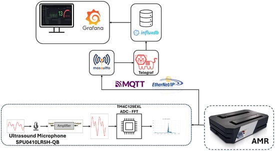
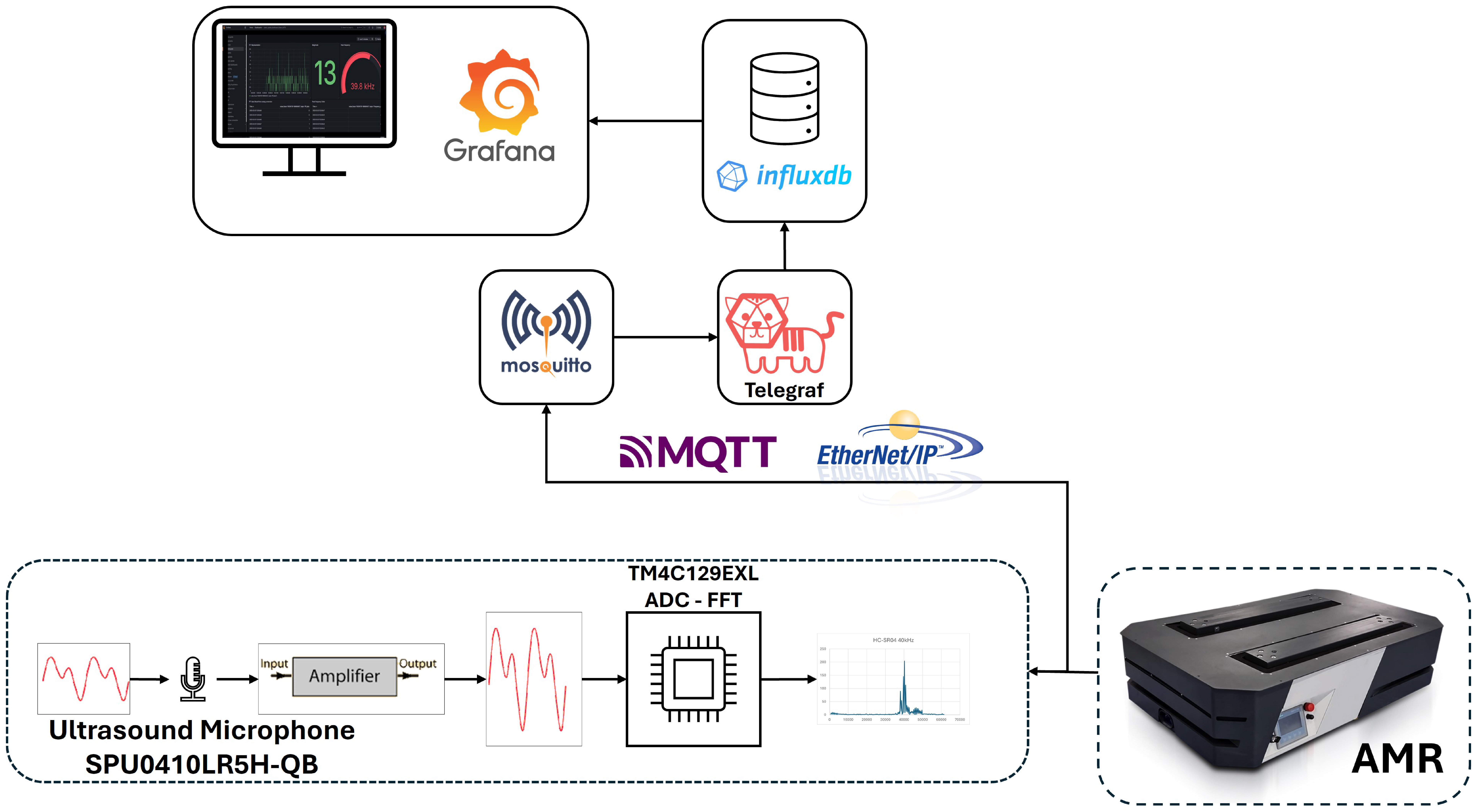
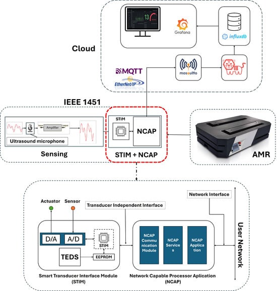
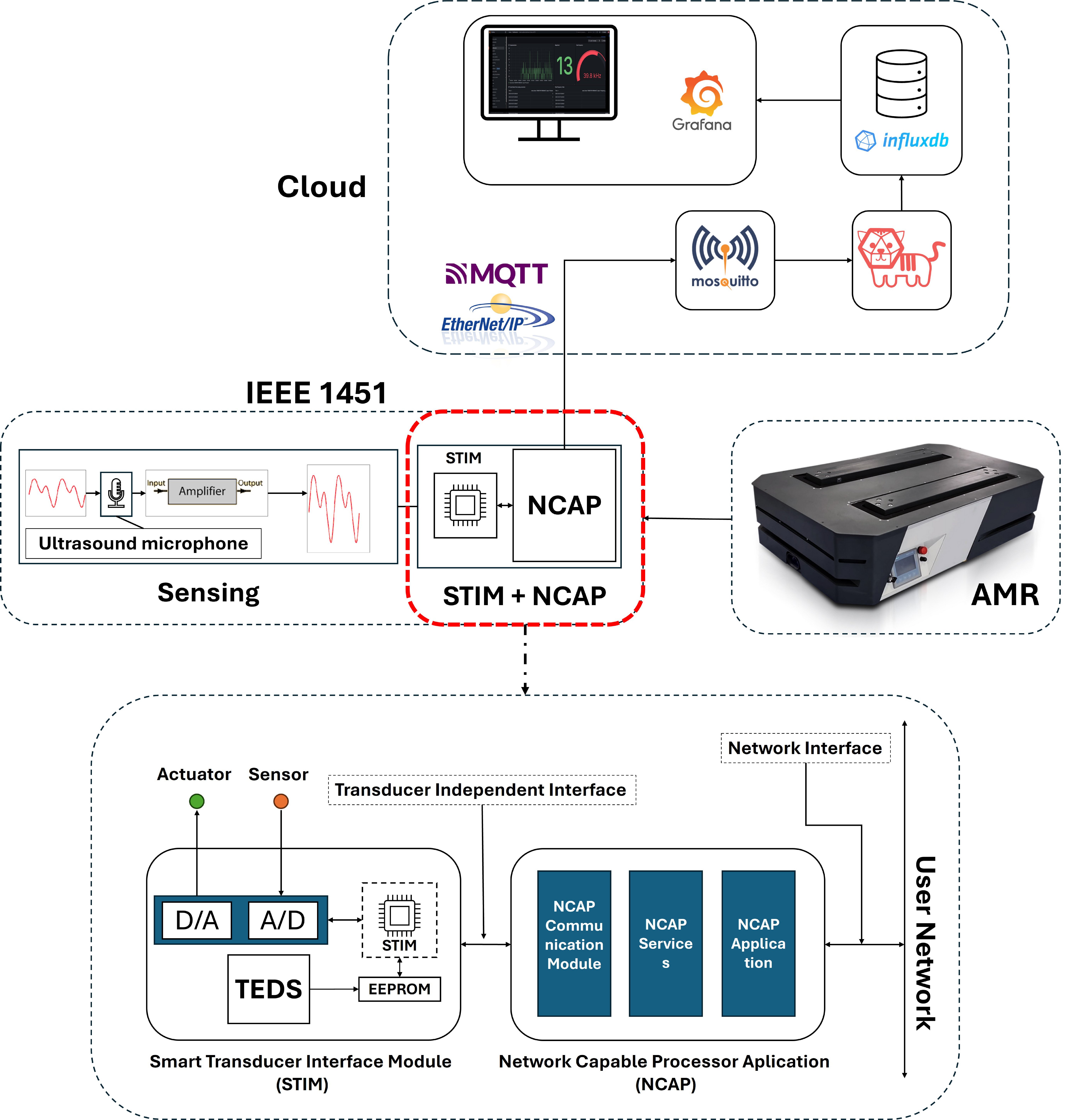
Figure 1 illustrates the system architecture for integration into AMRs, demonstrating a distributed configuration aimed at leveraging IIoT principles by integrating a sensing layer responsible for the capturing, processing, and transmission of ultrasound signals, and a cloud-based infrastructure that facilitates remote data aggregation and storage, as well as real-time data monitoring and visualization for enhanced decision-making tasks.
Figure 1.
System architecture for AMR integration.
4. Results
This section presents the experimental results obtained from acoustic signal acquisition tests. The tests evaluate the system’s performance in acquiring and processing acoustic signals using a window of 1024 samples, with a sampling rate of approximately 160 kHz, whereby the system achieves a frequency resolution of approximately 156 kHz. However, given the symmetry properties of real-value signals, only the first 512 frequency intervals (from 0 to 80 kHz) are analyzed and transmitted.
4.1. Scenario 1—Audible Range Validation
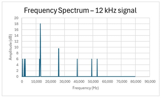
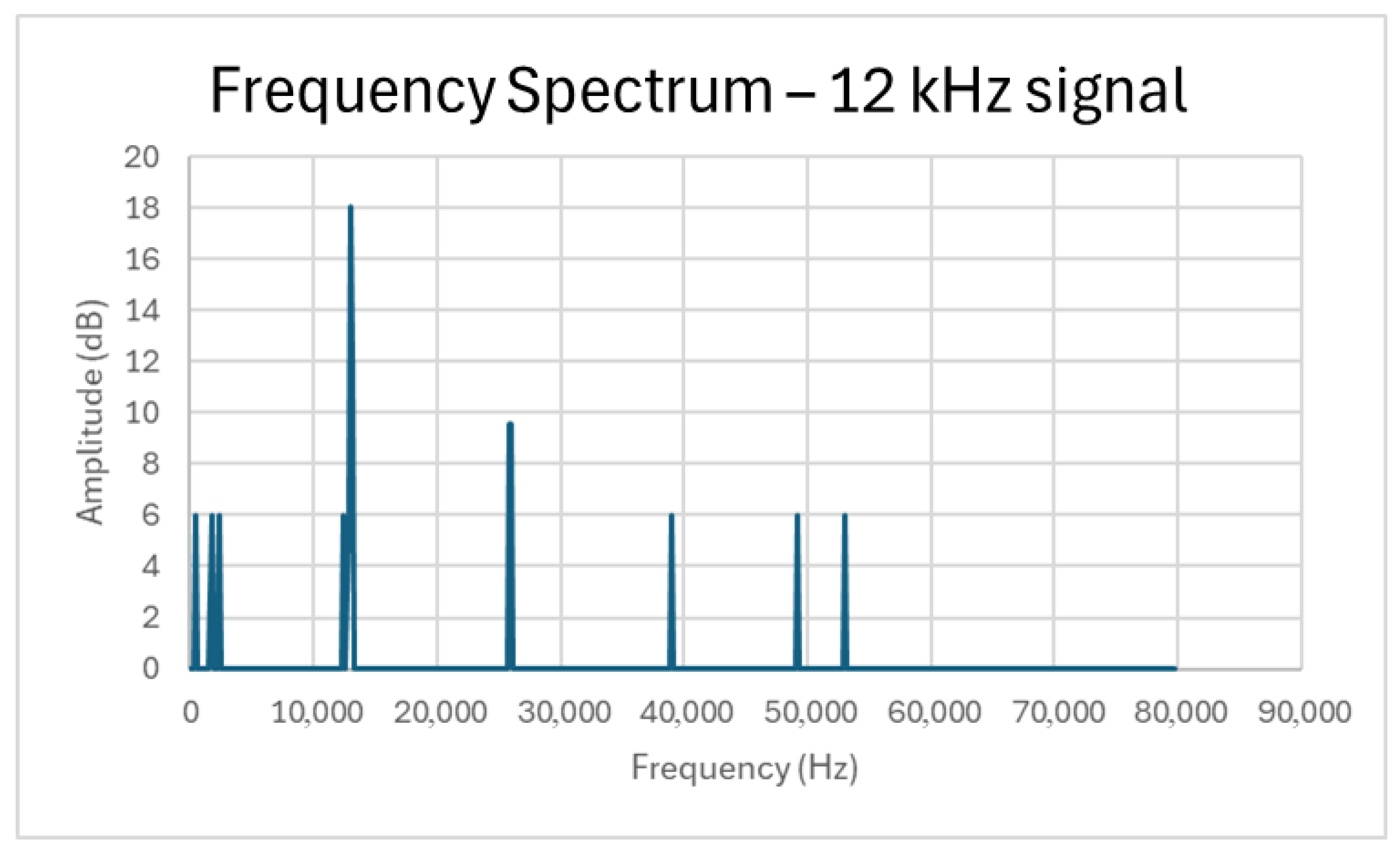
In the first scenario, the system acquired signals from a calibrated 12 kHz source. The data were processed using the fixed-point FFT with 1024 samples, considering the 512 frequency bins for analysis. Therefore, it was possible to acquire a spectrum where a prominent peak at approximately 12.8 kHz (bin 82) and a SNR of 18 dB were observed, as illustrated in Figure 2.
Figure 2.
Frequency test considering 12 kHz signal acquisition.
Statistical analysis from multiple acquisitions revealed a consistent systematic frequency deviation of approximately 6.7% from the nominal 12 kHz value. This offset is primarily attributed to the intrinsic latency in the microsecond timer interrupt routine in the microcontroller. Despite the constant deviation, the system exhibited high statistical repeatability, maintaining stable peak locations and consistent SNR values across all experimental trials, validating the reliability of the acquisition framework.
4.2. Scenario 2—Ultrasound Range Validation
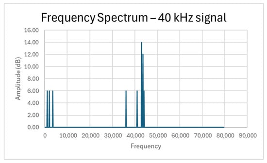
The second scenario focused on data acquisition within the ultrasonic range (>20 kHz) that leverages condition monitoring within the respective frequency range, while paving the way for early-stage anomaly detection. Therefore, to provide a stable high-frequency reference for validation, the HC-SR04 module was utilized as a calibrated 40 kHz piezoelectric emitter.
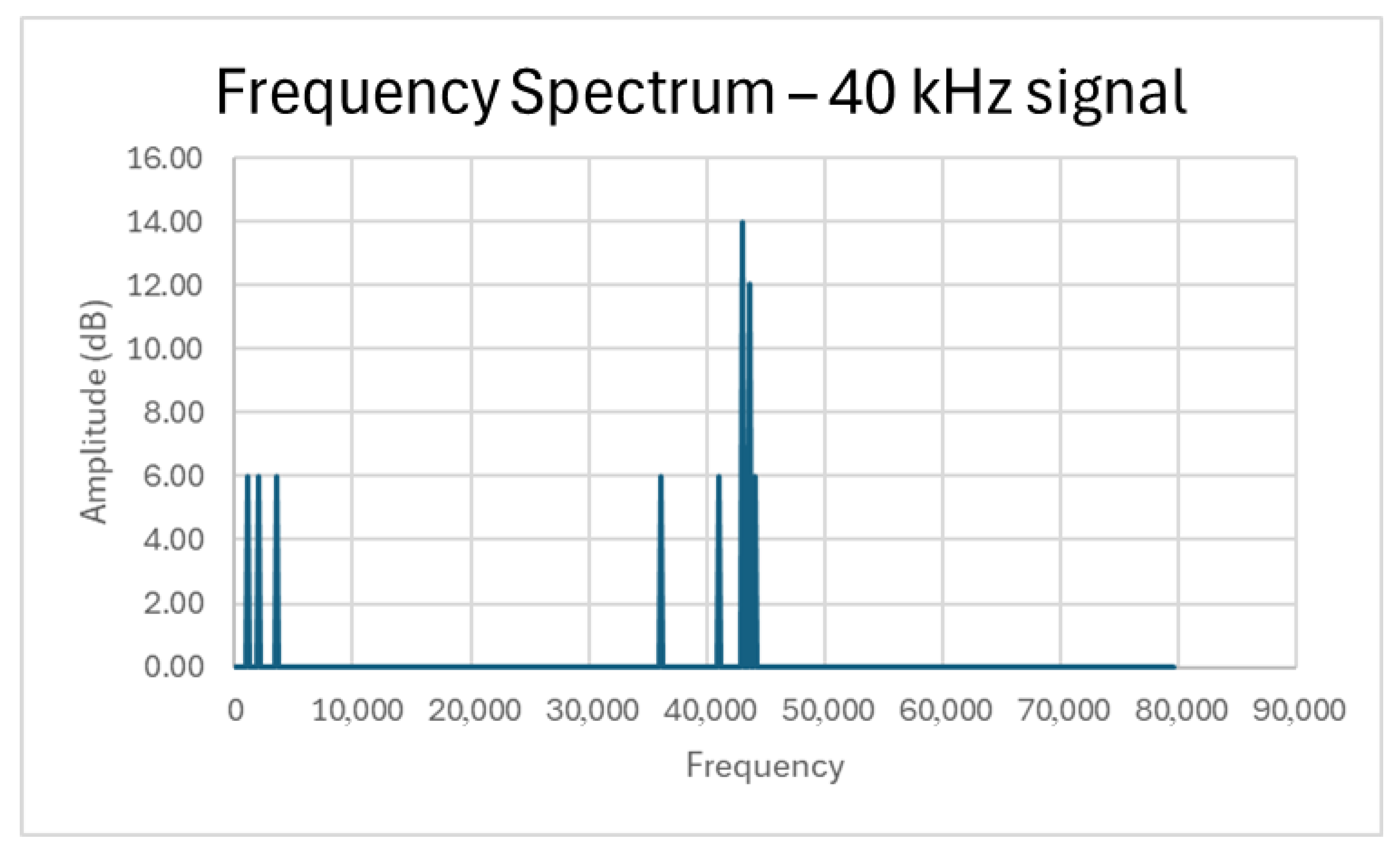
The system successfully acquired an ultrasonic signal, with the primary spectral energy concentrated in the high-frequency region. According to Figure 3, it demonstrated an acquired spectrum with a dominant peak centered at 42,968.75 Hz (bin 275), with a deviation of 7.4%. While this value is higher than the nominal 40 kHz center frequency, deviation is consistent with the systematic offset observed in the previous scenario. The 156.25 Hz resolution () provided by the 160 kHz sampling rate allows for clear isolation of this component from the background noise floor, which remains below 6 dB.
Figure 3.
Frequency Test considering 40 kHz signal acquisition.
4.3. Scenario 3—Simultaneous Ranges Validation
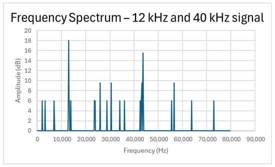
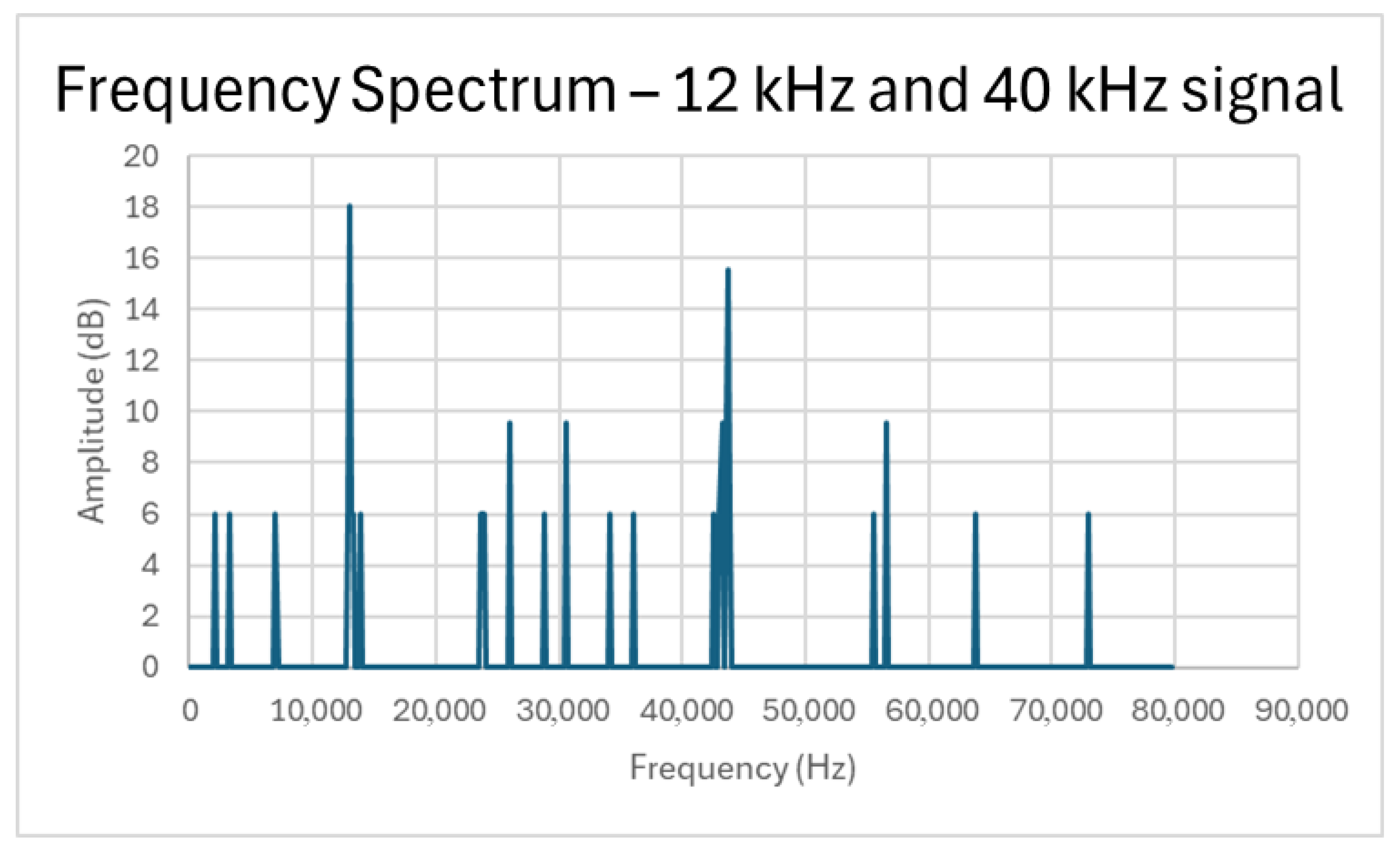
The final scenario considered simultaneous signal acquisition of both nominal frequencies 12 kHz and 40 kHz, according to the scenario described previously, aiming to assess the system’s reliability to distinguish and capture multiple frequency components. As depicted in Figure 4, the FFT results clearly resolve two distinct peaks. Consistent with the systematic frequency deviation observed in the previous individual tests, the peaks are registered at 12.81 Hz (bin 82) and 43.12 Hz (bin 276), while the amplitude and spectral integrity of both components were maintained relative to the single-signal scenarios, demonstrating the system’s robustness in multi-frequency environments without significant inter-band interference, as illustrated in Figure 4 as follows:
Figure 4.
Frequency test considering 12 and 40 kHz signal acquisition simultaneously.
4.4. Dashboard Visualization and Real-Time Monitoring
To demonstrate the end-to-end functionality of the proposed IIoT framework in a practical monitoring context, the processed data—FFT magnitude spectrum (in dB), detected peak frequency, and corresponding voltage amplitude—are transmitted via MQTT and ingested into the TIG stack. This enables real-time visualization, historical trending, and remote decision support for the predictive maintenance of AMR rotary motor bearings.
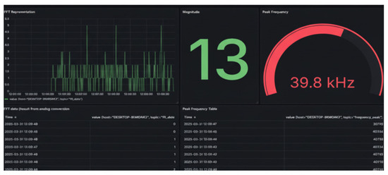
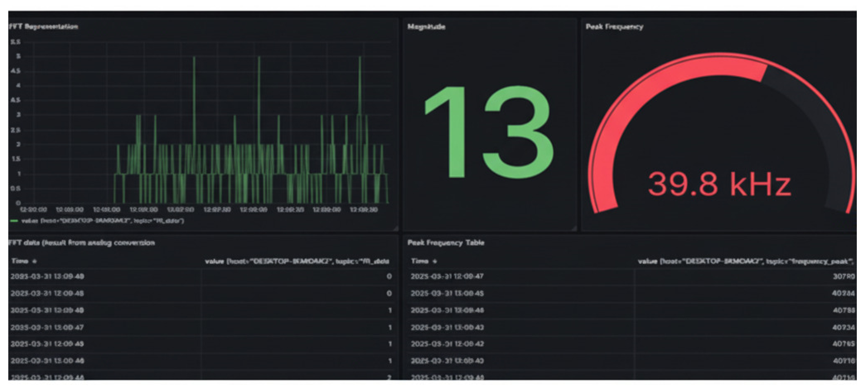
Figure 5 presents a representative dashboard view captured during operational testing. The interface is organized into several key panels:
Figure 5.
Developed dashboard for monitoring and data visualization.
- FFT Representation: A time-series line plot displays the full magnitude spectrum (dB scale) over recent acquisitions. The plot reveals the characteristic broadband ultrasonic content typical of mechanical systems. Prominent spectral features are visible as peaks and clusters, allowing operators to identify potential anomaly signatures (e.g., increased high-frequency energy or the emergence of fault-specific sidebands).
- Magnitude Peak Value: A large numeric indicator highlights the maximum magnitude observed in the latest FFT window (showing 13dB), providing an immediate quantitative measure of ultrasonic emission strength. Elevated values relative to baseline healthy conditions serve as a first-level alert threshold for incipient faults.
- Peak Frequency Gauge: A radial gauge prominently displays the dominant frequency of the strongest spectral peak, here registering 39.8 kHz ≈ 40 kHz emitted by the ultrasound sensor used for validation. This value falls squarely within the ultrasonic range where early-stage bearing faults commonly manifest first (typically 20–60 kHz for raceway/pitting defects under moderate speeds and loads). The gauge format facilitates comprehensive monitoring by maintenance personnel, with color-coding (green-to-red transition) to indicate deviation from expected healthy behavior.
- Recent Measurements Table: A tabular panel logs timestamped entries including FFT data ingestion time, peak voltage, and frequency values, enabling traceability and post-event analysis.
The dashboard layout supports both real-time oversight and historical review (via time-range selection and refresh controls), making it suitable for integration into AMR fleet management systems. During testing, the system consistently captured and visualized ultrasonic content around 40 kHz—consistent with controlled HC-SR04 validation (Scenario 2 and 3)—while the low-latency MQTT-to-Grafana pipeline ensured near-real-time updates (typically < 2 s end-to-end delay).
This visualization layer transforms raw ultrasonic sensor data into actionable monitoring insights, allowing the remote detection of anomalies in early stages before audible noise or vibration becomes significant, thereby reducing unplanned downtime in smart manufacturing environments.
5. Discussion
The experimental results demonstrate the effectiveness of the proposed architecture for acquiring and processing high-frequency acoustic signals across both audible and ultrasonic ranges, specifically at ≈12 kHz and 40 kHz. With the employment of MEMS ultrasound microphones, the potential for anomaly detection is revealed, providing a preliminary baseline identifying components exhibiting ultrasound fault signatures (such as bearings due to wear and lubrication issues). Therefore, the system’s development establishes a condition monitoring framework that leverages IIoT infrastructures for remote and real-time data monitoring and data analysis, while also paving the way for modern maintenance procedures aligned with Industry 4.0 principles.
Despite the system capturing peak frequencies, a notable observation in the experimental results is the systematic frequency shift (approximately 7%) across all scenarios. This discrepancy is attributed to the effective sampling rate achieved by the microcontroller’s software-triggered loop. For condition monitoring applications, this offset does not compromise system utility, as the framework relies on detecting relative shifts and energy increases in specific spectral bands rather than absolute frequency accuracy. The consistency of the peaks confirms that the calibration routine provides a stable, repeatable baseline. Regarding environmental robustness, while the MEMS sensor is omnidirectional and susceptible to reflections—as seen in the minor spectral spreading in Scenario 2—the signal-to-noise ratio remains sufficient to isolate primary mechanical components. In industrial environments, the ultrasonic range is typically less crowded by ambient noise than the audible spectrum, providing a “quieter” window for early-stage fault detection.
While leveraging aggregated time-series data for condition monitoring, with the potential for pattern recognition and fault prediction, to fully realize the potential of this framework for a more flexible, scalable, and interoperable system, especially within the heterogeneous ecosystem that is Industry 4.0, the incorporation of standardized smart transducer architecture demonstrates being essential. Thus, the IEEE 1451 standards developed by the Institute of Electrical and Electronics Engineers (IEEE) [12] emerges as a viable solution for establishing a set of common interfaces for connecting transducers from the most diverse manufacturers, and standardized data formats and communication protocols while enabling transducer Plug-and-Play functionalities for self-identification, self-configuration, data-processing, and standardized communication under the most diverse Industrial Communication Protocols (ICP). Additionally, the standards promote easy transducer integration with reduced installation and configuration timing, along with a faster solution for data acquisition and deployment with simplified maintenance and replacement, reducing the system’s downtime and consequently increasing productivity and efficiency performance [21].
The standard’s integration within the presented framework encompasses embedding Transducer Electronic Data Sheets (TEDS) in Erasable Programmable Read-Only Memory (EEPROM), storing critical transducer metadata such as identification, calibration parameters, measurement ranges, and manufacturer details, while enabling plug-and-play features, including self-diagnosis and time-awareness, emphasizing adapting parameters for evolving applications. Furthermore, a Network Capable Application Processor (NCAP) would link the Smart Transducer Interface Module (STIM) to the communication network, handling data conversion, triggering measurements, and ensuring raw data is transformed into engineering units upon reading the TEDS [22].
Given the distributed nature of AMR fleets and the need for real-time data exchange in IIoT infrastructures, since in the presented framework, MQTT already facilitates data transmission to the TIG stack, aligning with the IEEE 1451.1.6 [23] would standardize topics, payloads, and quality-of-service levels, ensuring secure, scalable communication across heterogeneous networks while addressing cybersecurity concerns through encrypted channels and authentication mechanisms. Additionally, the NCAP could enable inter-AMR communication via MQTT brokers, allowing fleet-wide anomaly sharing for collective PdM intelligence. This integration not only resolves noted challenges in IoT adoption but also opens opportunities for AI enhancements, such as edge-based ML models within the NCAP for real-time anomaly classification, further reducing latency and bandwidth demands. By leveraging these insights, the system gains robustness against vulnerabilities, as proposed in the review’s cybersecurity solutions, including secure TEDS access and protocol-level encryption [24].
The proposed architecture is illustrated in Figure 6 as follows:
Figure 6.
Proposed IEEE 1451 integration.
6. Conclusions
This paper presented the initial developments of a high-frequency condition monitoring framework designed to support future Predictive Maintenance (PdM) strategies for Autonomous Mobile Robots (AMRs) in a smart factory environment. By utilizing Micro-Electro-Mechanical System (MEMS) ultrasonic sensors for signal acquisition (>20 kHz), the system successfully performs real-time edge processing via a 1024-point fixed-point FFT on a resource-constrained microcontroller. The integration of an Industrial Internet of Things (IIoT) infrastructure—comprising MQTT and the TIG stack—demonstrates a reliable pipeline for remote data aggregation and visualization.
Experimental validation across the audible (12 kHz) and ultrasonic (40 kHz) ranges confirms the framework’s capability to isolate high-frequency signatures. Although a systematic frequency shift of approximately 7% was observed due to the effective sampling rate of the software-triggered acquisition loop, the results maintain high repeatability and spectral definition. This confirms that the architecture is suitable for detecting the relative energy increases associated with early-stage bearing degradation, such as lubrication starvation and micro-friction, which manifest in the ultrasonic spectrum before becoming detectable via traditional vibration or thermal analysis.
Furthermore, the paper discussed the integration of IEEE 1451 standards, providing a roadmap for addressing sensor interoperability and scalability. By proposing the use of Transducer Electronic Data Sheets (TEDS) and Network Capable Application Processors (NCAPs) with MQTT-compliant communication (IEEE 1451.1.6), the architecture supports a transition plug-and-play functionality, self-configuration, and secure data exchange across heterogeneous devices, paving the way for modular AMR fleets in dynamic industrial settings.
Future work will focus on transitioning from manual monitoring to automated diagnostics through the deployment of machine learning algorithms for anomaly classification. Additionally, empirical testing will be conducted within real-world AMR operational cycles under the GreenAuto project to assess the impact of dynamic movement and industrial background noise on signal clarity. These developments aim to produce a resilient, standardized, and maintenance-efficient ecosystem for next-generation smart manufacturing.
Author Contributions
Conceptualization, G.G. and V.H.P.; methodology, G.G. and V.H.P.; software, G.S.; validation, G.S., P.M.B.T., V.H.P. and G.G.; formal analysis, G.S., P.M.B.T., V.H.P. and G.G.; investigation, G.S.; resources, G.G.; data curation, G.S.; writing—original draft preparation, G.S.; writing—review and editing, P.M.B.T., V.H.P. and G.G.; visualization, G.S.; supervision, P.M.B.T., V.H.P. and G.G.; project administration, P.M.B.T., V.H.P. and G.G.; funding acquisition, V.H.P. and G.G. All authors have read and agreed to the published version of the manuscript.
Funding
The authors acknowledge the Project GreenAuto: Green Innovation for Automotive Industry project, nº C644867037-00000013, investment project nº 54, from the Incentive System to Mobilizing Agendas for Business Innovation, financed by the Recovery and Resilience Plan and by European Funds Next Generation EU. The authors also acknowledge Fundação para a Ciência e a Tecnologia (FCT) for its financial support via the project LA/P/0112/2020 (ARISE).
Data Availability Statement
Not applicable.
Acknowledgments
The authors would like to thank the SYSTEC-DIGI2 research team for their technical support during the experimental phase.
Conflicts of Interest
The authors declare no conflicts of interest.
Abbreviations
The following abbreviations are used in this manuscript:
| AMR | Autonomous Mobile Robots |
| ANN | Artificial Neural Networks |
| CPS | Cyber-Physical Systems |
| DCNN | Deep Convolutional Neural Networks |
| DFT | Discrete Fourier Transform |
| DNN | Deep Neural Networks |
| FFT | Fast Fourier Transform |
| IDE | Integrated Development Environment |
| IEEE | Institute of Electrical and Electronics Engineers |
| IIoT | Industrial Internet of Things |
| IoT | Internet of Things |
| KNN | K-Nearest Neighbor |
| MEMS | Micro-Electro-Mechanical Systems |
| ML | Machine Learning |
| MQTT | Message Queuing Telemetry Transport |
| PdM | Predictive Maintenance |
References
- Gholipour, Y. A Comprehensive Review of Maintenance Strategies: From Reactive to Proactive Approaches. SSRN Electron. J. 2025, 26, 70–83. [Google Scholar] [CrossRef] [Scilit]
- Mobley, R.K. An Introduction to Predictive Maintenance; Elsevier: Amsterdam, The Netherlands, 2002. [Google Scholar]
- Ghobakhloo, M. Industry 4.0, digitization, and opportunities for sustainability. J. Clean. Prod. 2020, 252, 119869. [Google Scholar] [CrossRef] [Scilit]
- Grönroos, C. On value and value creation in service: A management perspective. J. Creat. Value 2017, 3, 125–141. [Google Scholar] [CrossRef] [Scilit]
- Achouch, M.; Dimitrova, M.; Ziane, K.; Sattarpanah Karganroudi, S.; Dhouib, R.; Ibrahim, H.; Adda, M. On predictive maintenance in industry 4.0: Overview, models, and challenges. Appl. Sci. 2022, 12, 8081. [Google Scholar] [CrossRef] [Scilit]
- Nassif, A.B.; Talib, M.A.; Nasir, Q.; Dakalbab, F.M. Machine learning for anomaly detection: A systematic review. IEEE Access 2021, 9, 78658–78700. [Google Scholar] [CrossRef] [Scilit]
- Wuest, T.; Weimer, D.; Irgens, C.; Thoben, K.D. Machine learning in manufacturing: Advantages, challenges, and applications. Prod. Manuf. Res. 2016, 4, 23–45. [Google Scholar] [CrossRef] [Scilit]
- Simeu-Abazi, Z.; Iung, B.; Leger, J.B.; Ly, F. Maintenance in the manufacturing systems. IFAC Proc. Vol. 2000, 33, 831–836. [Google Scholar] [CrossRef] [Scilit]
- Murphy, C. Choosing the Most Suitable Predictive Maintenance Sensor; Analog Devices Inc.: Wilmington, MA, USA, 2020. [Google Scholar]
- Sun, S.; Zheng, X.; Villalba-Díez, J.; Ordieres-Meré, J. Data handling in industry 4.0: Interoperability based on distributed ledger technology. Sensors 2020, 20, 3046. [Google Scholar] [CrossRef] [Scilit] [PubMed]
- Li, T.; Song, B.; Liu, Y.; Jiang, B.; Yu, C. Research on Ultrasonic Detection Technology of Overhead Distribution Line. In Proceedings of the 2021 IEEE International Conference on Artificial Intelligence and Computer Applications (ICAICA); IEEE: New York, NY, USA, 2021; pp. 938–942. [Google Scholar] [CrossRef] [Scilit]
- IEEE Std 1451.0-2024; IEEE Standard for a Smart Transducer Interface for Sensors and Actuators–Common Functions, Communication Protocols, and Transducer Electronic Data Sheet (TEDS) Formats; Revision of 1451.0-2007. IEEE: New York, NY, USA, 2024; pp. 1–429. [CrossRef] [Scilit]
- Rubio, E.M.; Dionísio, R.P.; Torres, P.M.B. Predictive maintenance of induction motors in the context of industry 4.0. Int. J. 2018, 4, 238. [Google Scholar]
- Cui, B.; Weng, Y.; Zhang, N. A feature extraction and machine learning framework for bearing fault diagnosis. Renew. Energy 2022, 191, 987–997. [Google Scholar] [CrossRef] [Scilit]
- Suawa, P.F.; Halbinger, A.; Jongmanns, M.; Reichenbach, M. Noise-robust machine learning models for predictive maintenance applications. IEEE Sens. J. 2023, 23, 15081–15092. [Google Scholar] [CrossRef] [Scilit]
- Oliveira, D.; Pinheiro, J.; Neto, L.; Pinto, V.H.; Gonçalves, G. A plug-and-play solution for smart transducers in industrial applications based on IEEE 1451 and IEC 61499 standards. Sensors 2022, 22, 7694. [Google Scholar] [CrossRef] [Scilit] [PubMed]
- Buonocore, D.; Carratù, M.; Ciavolino, G.; Ferro, M.; Marino, M.; Paciello, V. Development of a Smart Sensor Framework for Predictive Maintenance. In Proceedings of the 2024 IEEE International Workshop on Metrology for Industry 4.0 & IoT (MetroInd4. 0 & IoT); IEEE: New York, NY, USA, 2024; pp. 361–365. [Google Scholar]
- Da Rocha, H.; Chen, G.; Li, E.; Salvado, J.A.; Espirito-Santo, A. Smart Transducers, Robotics and Artificial Intelligence in Industry 4.0. In Proceedings of the 2025 IEEE International Conference on Industrial Technology (ICIT); IEEE: New York, NY, USA, 2025; pp. 1–6. [Google Scholar]
- Milburn, F. FFT. 2016. Available online: https://github.com/fmilburn3/FFT/blob/master/fix_fft.h (accessed on 15 May 2025).
- Drăgulinescu, A.M.; Marcu, I.; Zamfirescu, C. An End-to-End LoRaWAN-based IoT Platform with Built-in Network Coverage Testing Capability. In Proceedings of the 2022 25th International Symposium on Wireless Personal Multimedia Communications (WPMC); IEEE: New York, NY, USA, 2022; pp. 474–479. [Google Scholar]
- Saponara, S.; Petri, E.; Fanucci, L.; Terreni, P. Smart transducer interface in embedded systems for networked sensors based on the emerging IEEE 1451 standard: H2 detection case study. In Proceedings of the 2009 Seventh Workshop on Intelligent Solutions in Embedded Systems; IEEE: New York, NY, USA, 2009; pp. 49–55. [Google Scholar]
- Song, E.Y.; Lee, K. Understanding IEEE 1451-Networked smart transducer interface standard —What is a smart transducer? IEEE Instrum. Meas. Mag. 2008, 11, 11–17. [Google Scholar] [CrossRef] [Scilit]
- IEEE P1451.1.6/D04; IEEE Draft Standard for a Smart Transducer Interface for Sensors, Actuators, and Devices—Message Queue Telemetry Transport (MQTT) for Networked Device Communication. IEEE: New York, NY, USA, 2025; pp. 1–83.
- Spencer, G.; Torres, P.; Gonçalves, G.M. A Systematic Review on the IEEE 1451 Standards: Current Status, Challenges, and Opportunities. IEEE Sens. J. 2025, 25, 35735–35756. [Google Scholar] [CrossRef] [Scilit]
Disclaimer/Publisher’s Note: The statements, opinions and data contained in all publications are solely those of the individual author(s) and contributor(s) and not of MDPI and/or the editor(s). MDPI and/or the editor(s) disclaim responsibility for any injury to people or property resulting from any ideas, methods, instructions or products referred to in the content. |
© 2026 by the authors. Licensee MDPI, Basel, Switzerland. This article is an open access article distributed under the terms and conditions of the Creative Commons Attribution (CC BY) license.