


Abstract
Combining with the wheel–rail rolling contact models and extended finite element method (XFEM), this study systematically analyses the influence of wheel thermal expansion induced by braking thermal load on the tread cracking behavior of railway freight trains during the emergency braking process. Unlike the well-documented effect of material softening at elevated temperatures, the key contribution of this work lies in identifying and elucidating the dominant role of thermally induced geometrical changes in the contact conditions. The results demonstrate that wheel thermal expansion significantly alters the shape of the contact spot and the stress distribution, thereby reconstructing the mechanical driving force at the crack tip. Specifically, thermal expansion effectively suppresses Mode I cracking. Although it slightly reduces the magnitude of ΔKII, the primary and critical outcome is a distinct shift in the location of the maximum ΔKII from the deep interior of the crack to its superficial outer tip, driven by the altered contact geometry. This shift intensifies the crack propagation trend along the length direction near the surface. Therefore, although the nominal contact stress decreases when considering braking heat, the risk of surface-initiated damage increases, which needs to be paid attention to during operations and maintenance.
1. Introduction
Tread braking, as one of the primary braking methods for freight trains, achieves rapid conversion of kinetic-to-thermal energy through friction between brake shoes and the wheel tread. During the braking process, the intense friction at the friction interface leads to significant thermal mechanical response on the wheel tread. Research demonstrates that wheel tread cracks predominantly originate from the synergistic effects of thermal braking loads and wheel–rail rolling contact loads [1,2]. Severe thermal loads induce wheel thermal expansion and material softening [3], which accelerate the fatigue damage [4] and shorten the wheel’s service life [5]. The tread cracks not only trigger fluctuations in wheel–rail contact forces but also compromise wheel structural integrity, posing critical safety risks to train operations [6]. Consequently, elucidating the evolution mechanisms of tread cracks under wheel thermal expansion holds significant engineering importance for ensuring freight railway safety.
In recent years, extensive studies have focused on tread thermal fatigue. Walia et al. [7] systematically analyzed the evolution of tread temperature fields under varying braking parameters using the finite element (FE) method, revealing nonlinear material constitutive behavior in high-temperature environments and the pronounced degradation of wheel thermal–mechanical load-bearing capacity. Landström et al. [8] quantified the non-uniformity of thermal distribution during braking through combined experimental and FE approaches, and found that local overheating can lead to high residual tensile stress, significantly increasing the risk of early wheel failure. Liu et al. [9] integrated friction experiments with microscopic characterization to clarify temperature-induced yield strength softening and plastic flow accumulation mechanisms, providing microstructural evidence for crack initiation. Esmaeili et al. [10] experimentally investigated thermal–mechanical damage mechanisms, demonstrating that rising braking temperature reduces wheel material hardness and alters fatigue damage behavior. Chandak et al. [11] employed FE models to study crack propagation under elevated temperatures, concluding that high braking temperature accelerates crack growth and reduces service life.
Regarding the rolling contact fatigue problem of the wheel tread, Ekberg and Sotkovszki [12] highlighted that RCF can lead to further failures such as tread spalling. RCF behavior is influenced by multiple factors, including wheel–rail material properties [13], wheel geometry [14], and axle load distribution. Zhang et al. [15] proposed a multiscale framework combining shakedown maps and critical plane methods for predicting RCF crack initiation. Maglio et al. [16] demonstrated through experiments and numerical simulations that tread damage amplifies wheel–rail impact loads, exacerbating RCF of the wheel tread. Caprioli [17] conducted 3D elastoplastic FE simulations to compare the hazards of radial (thermal) cracks and inclined RCF cracks, revealing that inclined cracks exhibit maximum shear displacements at crack tips, with Mode II-dominated propagation. Kato et al. [18] integrated FE stress analysis, Pommier-based stress intensity factor calculations, and Charpy impact tests to predict vertical split rim crack occurrences, demonstrating that high-toughness wheel steels reduce crack incidence by 95% compared to conventional wheels. Canadinc et al. [19] further incorporated material elastoplasticity into FE models to analyze the effects of contact pressure and crack surface friction on propagation rates, advancing RCF life prediction methodologies.
It should be noted that under high-temperature braking conditions, thermal expansion not only alters the mechanical properties of materials but, more importantly, it also reconstructs the contact state by changing the macroscopic geometry of the contacting bodies [20,21]. The significance of temperature’s direct impact on the contact mechanism of friction pairs has been confirmed in research on braking systems [22,23]. Furthermore, the analytical method for multi-stress coupled systems has been applied to evaluate reliability under thermal and mechanical loads, highlighting the importance of a systematic approach in studying such interactions [24].
Regarding the coupled effect of thermal expansion and wheel–rail contact, existing research implicitly attributes the impact of thermal expansion to stress redistribution caused by material softening at high temperatures, while lacking in-depth exploration of the induced geometric deformation of the contact patch and its direct impact on tread crack driving force. For instance, Wei et al. [25] revealed through experiments and simulations that the thermo-mechanical coupling effect on the wheel–rail contact surface easily induces numerous cracks. He et al. [26] noticed the influence of thermal expansion when studying the propagation of tread cracks during braking, but did not systematically elucidate the driving mechanism by which thermal expansion alters the crack propagation behavior. Handa et al. [27] discovered through the tread braking experiments conducted using actual railway wheels that the compressive stress caused by the combined wheel–rail rolling contact and the thermal expansion was one of the important factors leading to the generation of the tread thermal cracks in the region from the surface to a depth of 500 μm. Caprioli et al. [28] combined a full-scale braking test with finite element simulations to verify the prediction model for thermal cracks on railway wheel treads and found that local high temperatures on the tread are more likely to cause tread cracks. As pointed out by Ekberg and Sotkovszki [12] and recent analysis by Maglio et al. [16], changes in tread profile caused by non-uniform temperature fields can significantly alter the shape and location of the wheel–rail contact patch. Therefore, elucidating how geometric deformation caused by thermal expansion interacts with wheel–rail rolling contact, thereby affecting the propagation behavior of tread cracks, has become an urgent issue to be addressed. In this work, in response to the fatigue damage problem of the wheel tread of railway freight trains during the braking process, with the help of the heat flux density loading method, wheel–rail rolling contact finite element model and the extended finite element method, the combined influence of braking heat and thermal expansion on the tread crack of railway wheels is analyzed.
2. Model Description
2.1. Finite Element Model
The three-dimensional geometric model is established according to the actual dimensions of the freight train, including a wheel and a rail. The wheels are the ones currently in service in China, and the wheel type is HESA with a tread mode of LM, and the diameter of the wheel is 786 mm. The material of the wheel is CL60, with a density of 7850 kg/m3, Poisson’s ratio of 0.3, and other material parameters of the wheel are shown in Table 1. The rail is a 60 kg/m rail, and the rail cant is 1/40, with a density of 7850 kg/m3, elasticity modulus of 1.93 × 10⁵ MPa, and Poisson’s ratio of 0.3.
Table 1.
Wheel material [29].
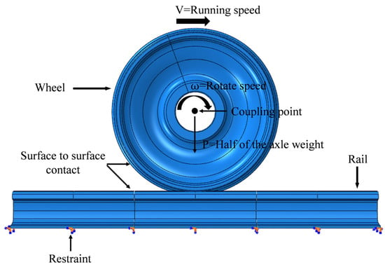
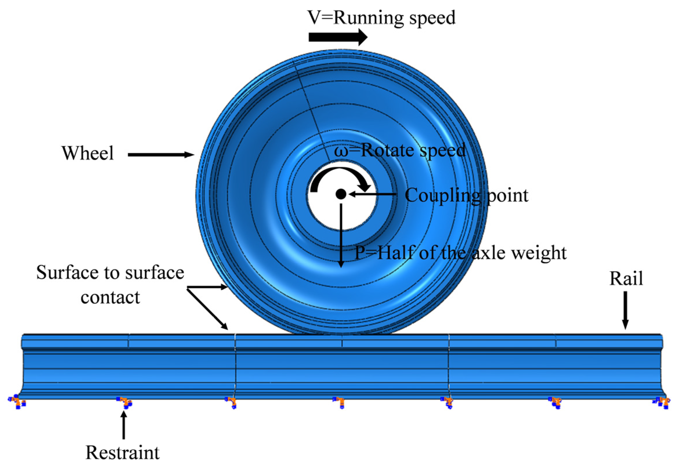
The application of boundary conditions for wheel–rail contact is mainly divided into two steps: one is to establish static wheel–rail contact, and the other is to simulate wheel–rail rolling contact based on the static contact results. The boundary conditions are described in Figure 1. A coupling point is established in the center of the wheel, coupled with the inner bore of the wheel, and a vertical force P is applied to the reference point to simulate the weight of the vehicle. The rotational speed ω and the translational velocity V are applied to the wheel to simulate the operation of the vehicle. The rail constraints are applied to the bottom of the rail. Face-to-face contact is established for the wheels and the rail, the normal behavior is described by a hard contact configuration, the tangential behavior adopts the penalty function, and the friction coefficient between the wheel and the rail is set to 0.3 [30].
Figure 1.
Wheel–rail contact boundary conditions.
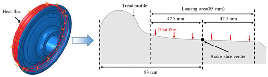
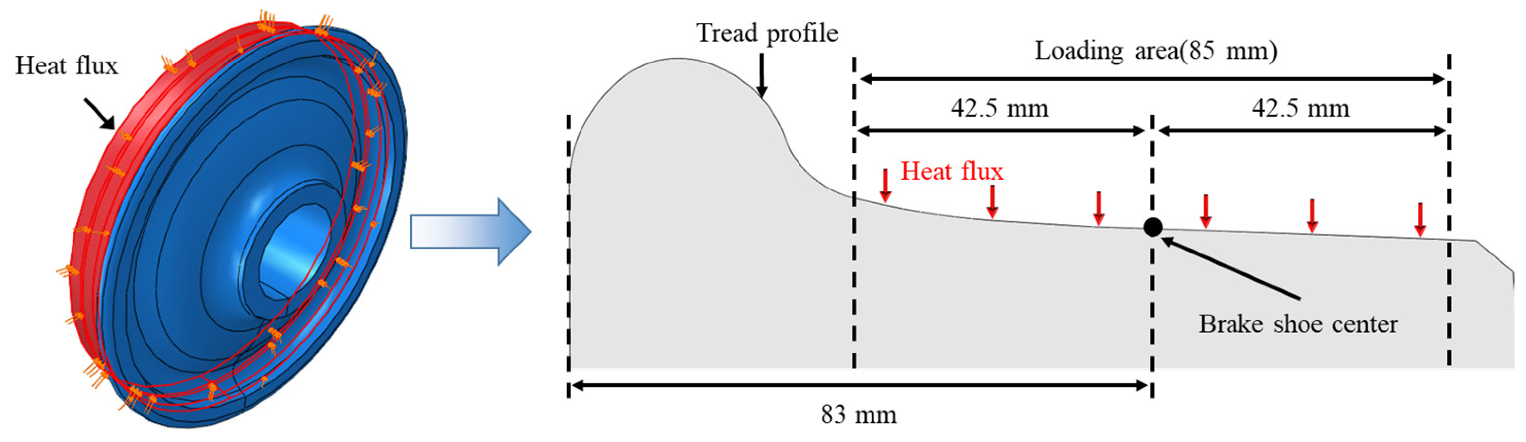
In the tread braking process of a freight train, the temperature rise on the tread is mainly caused by wheel–brake shoe friction [31]. In order to simulate the heat generated by wheel–brake shoe friction in the tread braking process, the uniform heat source method is used in the finite element model, and the uniform heat flux is applied on the wheel–brake shoe contact area on the wheel tread. Although in practical situations, the tread heat input is a moving rotating heat source, and due to factors such as surface roughness and material non-uniformity, the actual heat input may exhibit spatial non-uniformity and lead to the occurrence of local hotspots [10]. For calculating the temperature field and stress field of the wheel tread during the braking process, the errors obtained using the moving heat source method and the uniform heat source method are within 5% [32]. Therefore, for computational efficiency and model simplification, the uniform heat source method is used in this work, and the uniform heat flux is applied on the wheel–brake shoe contact area. In this study, the input range of heat load on the wheel tread is determined with reference to TB/T 3463-2016 [33]. The location of heat flux loading is shown in Figure 2.
Figure 2.
The location of the heat flux loading.
The heat generated during the braking process is shared by the wheels and the brake shoes. Therefore, the heat flux density q input to the wheel tread can be calculated according to Equation (1):
where represents the heat flux partition coefficient, indicates the brake shoe–wheel friction coefficient, denotes the brake shoe pressure (N), the real-time train speed (m/s) and the brake shoe contact band area (m2) are represented by and , respectively. The heat flux partition coefficient can be expressed using the following formula,
where represents the heat dissipation coefficient, the wheel and the brake shoe are represented by subscript w and s, respectively. The heat dissipation coefficient can be calculated according to Equation (3):
where represents the heat conductivity coefficient (W/(m·°C)), indicates the density (kg/m3), denotes the heat capacity (J/(kg·°C)). The brake shoe utilizes high-friction composite material with the density of 2340 kg/m3, heat expansion coefficient of 0.46 × 10⁻⁶ °C−1, heat conductivity coefficient of 0.997 W/(m·°C) and heat capacity of 520 J/(kg·°C).
The brake shoe–wheel friction coefficient is calculated according to the formula specified in TB/T 1047.1-2018 [34],
The ambient temperature during freight train operation is set to 25 °C, and the convective heat transfer coefficient is assigned a value of 22.713 W/(m2·°C) [33].
2.2. Crack Model
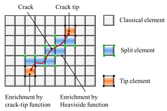
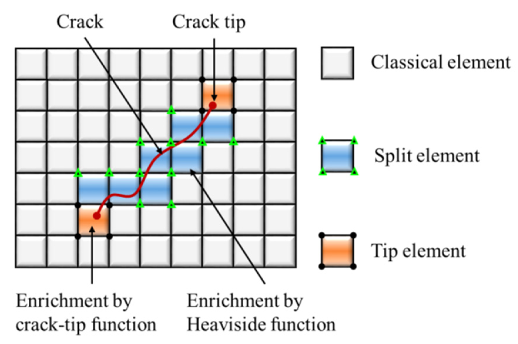
The study uses the extended finite element method (XFEM) to calculate the stress intensity factor of the tread crack and analyzes the cracking behavior. The extended finite element method (XFEM) is an advanced numerical analysis technique based on the traditional finite element method (FEM), which overcomes the limitation of FEM that requires frequent re-meshing when simulating crack propagation by introducing enrichment functions to deal with discontinuities, such as cracks and interfaces [35]. The core mechanism of XFEM lies in the fact that the enrichment functions are embedded into the approximation space of the finite element, which is capable of efficiently describing the singularities and discontinuities at the crack tip. This significantly improves the computational accuracy and efficiency. Its feature of not requiring re-meshing greatly reduces the computational cost, while being able to couple with multi-physics fields. As shown in Figure 3, only a few elements that are crossed by the crack are enriched, and the rest are standard elements.
Figure 3.
Enrichment functions in XFEM.
The displacement field in the region where the cracks occur can be divided into the standard part and the enriched part. It can be described by the following formula,
where the standard part and the enriched part are represented by and , respectively.
The enriched part of displacement can be obtained by the split element and the tip element. The displacement field in the region where the cracks occur can be described by the following formula,
where N represents the standard finite element shape function, represents the displacement field of the continuous domain, the enriched degrees of freedom of the far-field and the enriched degrees of crack tip regions are represented by b and c, respectively. H indicates the Heaviside enrichment function for crack surface discontinuity. denotes the crack tip enrichment function, and it can be described by the following formula,
where and are polar coordinates with the origin at the crack tip.
The stress intensity factor (SIF), an important concept in fracture mechanics, was first proposed by Irwin [36,37,38]. The stress intensity factor is related to the geometry of the component, the size of the crack, and the distribution of the load. Under different loading conditions, the crack propagation forms can be classified into three models: model I propagation, model II propagation and model III propagation. Correspondingly, the stress intensity factors can be divided into three components: KI, KII and KIII. The analysis of crack propagation under cyclic loading typically uses ∆K, and it can be described by the following formula,
∆KI = max(KI) − max(min(KI), 0)
∆KII = max(KII) − min(KII)
∆KIII = max(KIII) − min(KIII)
It should be noted that when the stress intensity factor KI is negative, the crack faces are under compression and remain closed. Under such conditions, the crack tip does not experience tensile stresses that would drive Mode I crack propagation. Therefore, in line with common practice in fatigue crack growth analysis, the compressive part of Mode I propagation is often considered non-damaging and is effectively neglected when calculating the driving force ΔK for crack propagation.
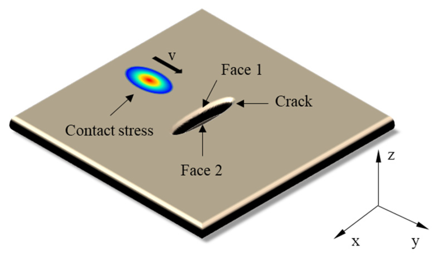
In this work, the definitions of positive and negative values of the stress intensity factor are as follows, as shown in Figure 4. When the crack face on the left (Face 1) and the crack face on the right (Face 2) open along the y-axis direction, KI is positive. When Face 1 undergoes a relative displacement along the negative z-axis direction with respect to Face 2, KII is positive. When Face 1 undergoes a relative displacement along the positive x-axis direction with respect to Face 2, KIII is positive.
Figure 4.
Diagrams showing the direction of crack propagation.
For K, this paper adopts the interaction integral method to calculate the J integral at the crack tip and thereby derive K. The J integral is a function used to describe the stress field at the crack tip and applicable under both elastic conditions and small-scale yielding conditions. It can be described by the following formula,
where A represents any arbitrary path along the crack tip in the counterclockwise direction, T is the component of the traction vector, u is the component of the displacement vector, ds is the incremental length of the path Γ, and w is the strain energy density.
For homogeneous and isotropic materials, the relationship between J integral and K is shown in Formula (10),
where E represents the Young’s modulus of the material, K represents the stress intensity factor, G represents the shear modulus, and G = E/2 (1 + ), where ν is Poisson’s ratio.
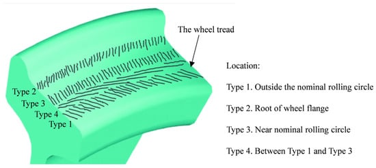
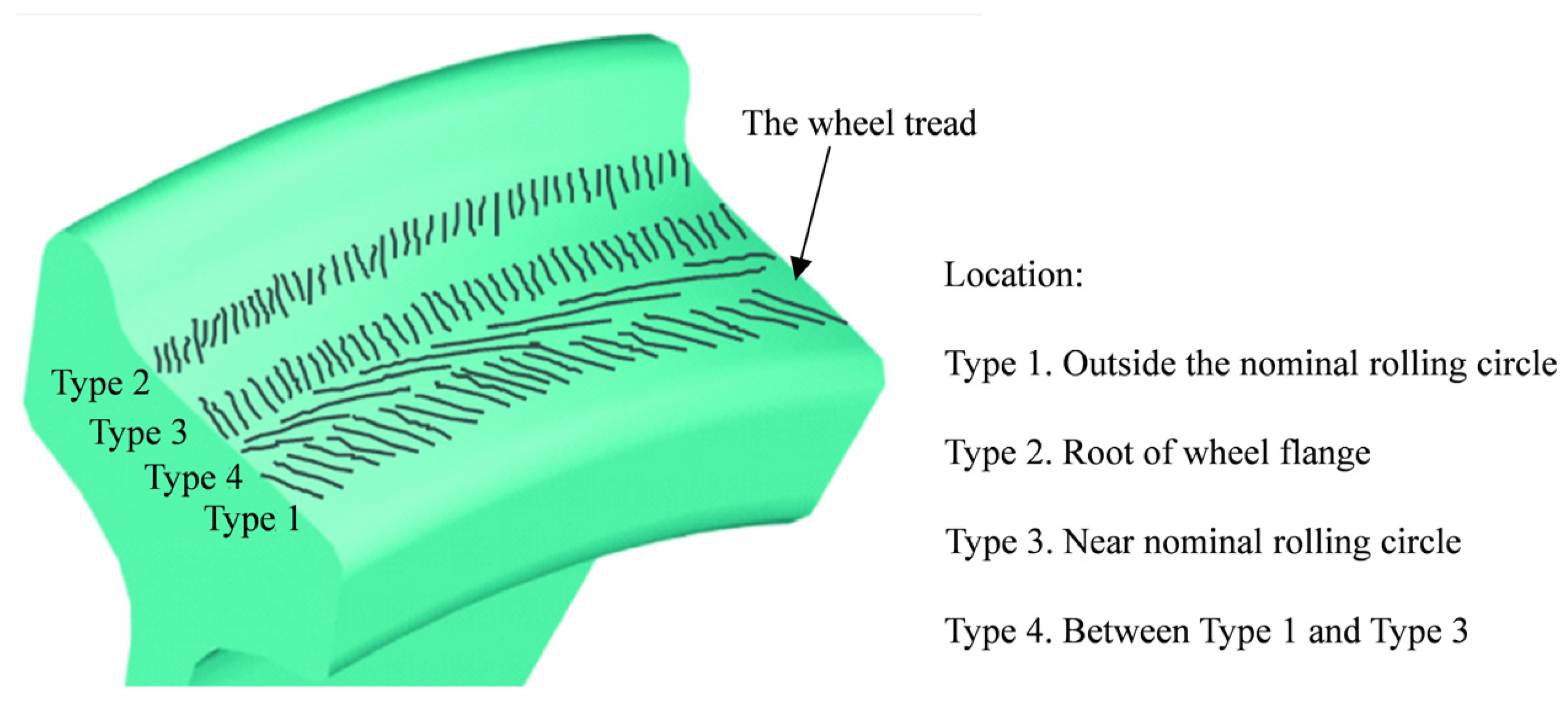
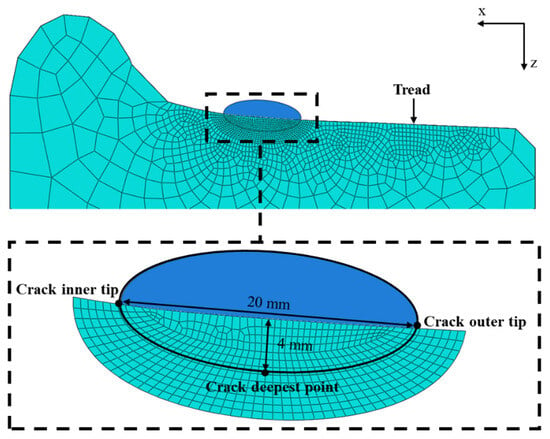
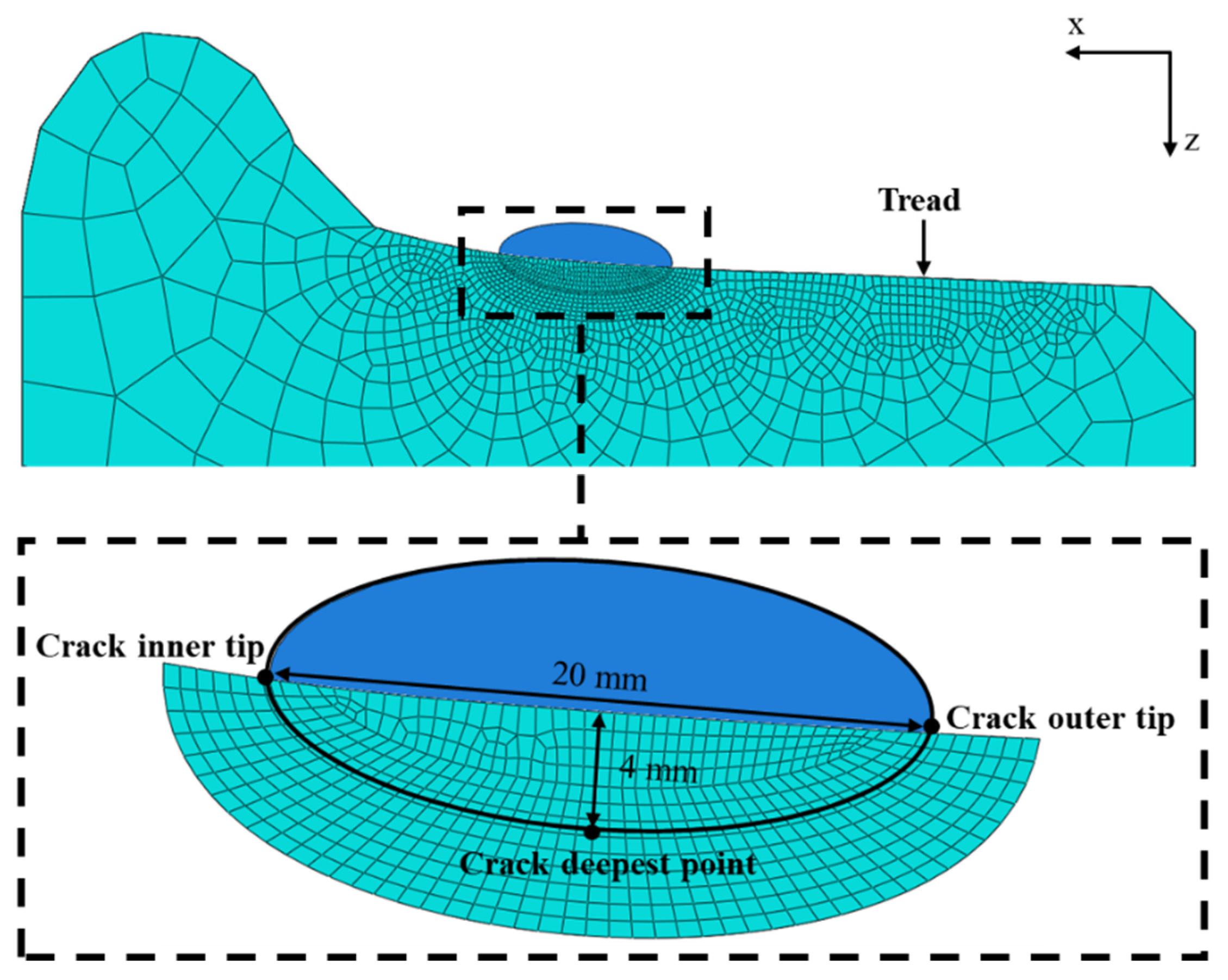
Studies have shown that thermal tread cracks are mostly semi-elliptical cracks [6], and under the combined influence of circumferential thermal stresses from braking and rolling contact force between wheel and rail, these cracks are mostly transverse cracks (perpendicular to the running direction). As shown in Figure 5, Deuce [39] classified tread cracks into four types based on lateral positions of cracks initiation: tread cracks located outside the nominal rolling circle of the wheel are classified as the first type of crack; those at the root of the wheel flange are classified as the second type of crack; those near the nominal rolling circle of the wheel are classified as the third type of crack; and the fourth type of crack originates between the first and third types of cracks. According to Deuce’s classification, the tread cracks analyzed in this article belong to the third type of tread cracks, which are located around the nominal rolling circle of the wheel. Handa’s research [27] further indicates that the length of the tread transverse crack is around 20–30 mm, and the depth of the cracks is around 4–7 mm. Therefore, in this study, the length of the tread crack is set to 20 mm, and the depth of the tread crack is set to 4 mm; the center of the tread crack is located at the position of the maximum contact stress point of the tread.
Figure 5.
Classification of tread cracks [40].
For the meshing of the model, the mesh size should not only meet the mesh accuracy requirements for wheel–rail contact simulation, but also meet the mesh accuracy requirements for XFEM. Referring to the study of Zhao and Li [41], this paper determines that the mesh size of the wheel–rail contact region is 0.5 × 0.5 mm. At the same time, to ensure the consistency of the mesh between the wheel–rail contact region and the tread crack region, the mesh size of the tread crack region is also selected to be 0.5 × 0.5 mm, as shown in Figure 6. Simultaneously, a distance normalization process was applied along the crack front, with the crack inner tip defined as 0, the deepest point as 0.5, and the crack outer tip as 1.
Figure 6.
Tread crack size and mesh division.
2.3. Model Verification
In order to ensure the accuracy of the calculation, the finite element solution of wheel–rail contact is compared and verified with the Hertz theory. Hertz theory [42] serves as a classic framework for addressing contact problems. Given that this study primarily focuses on the contact near the rail head and the nominal rolling circle of the wheel tread, which falls within the scope of Hertz’s theory, using its results as a benchmark can effectively verify the accuracy of the finite element model developed in this study in terms of contact analysis.
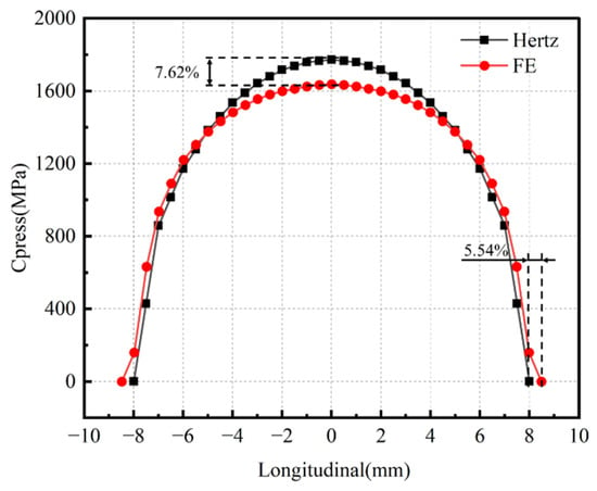
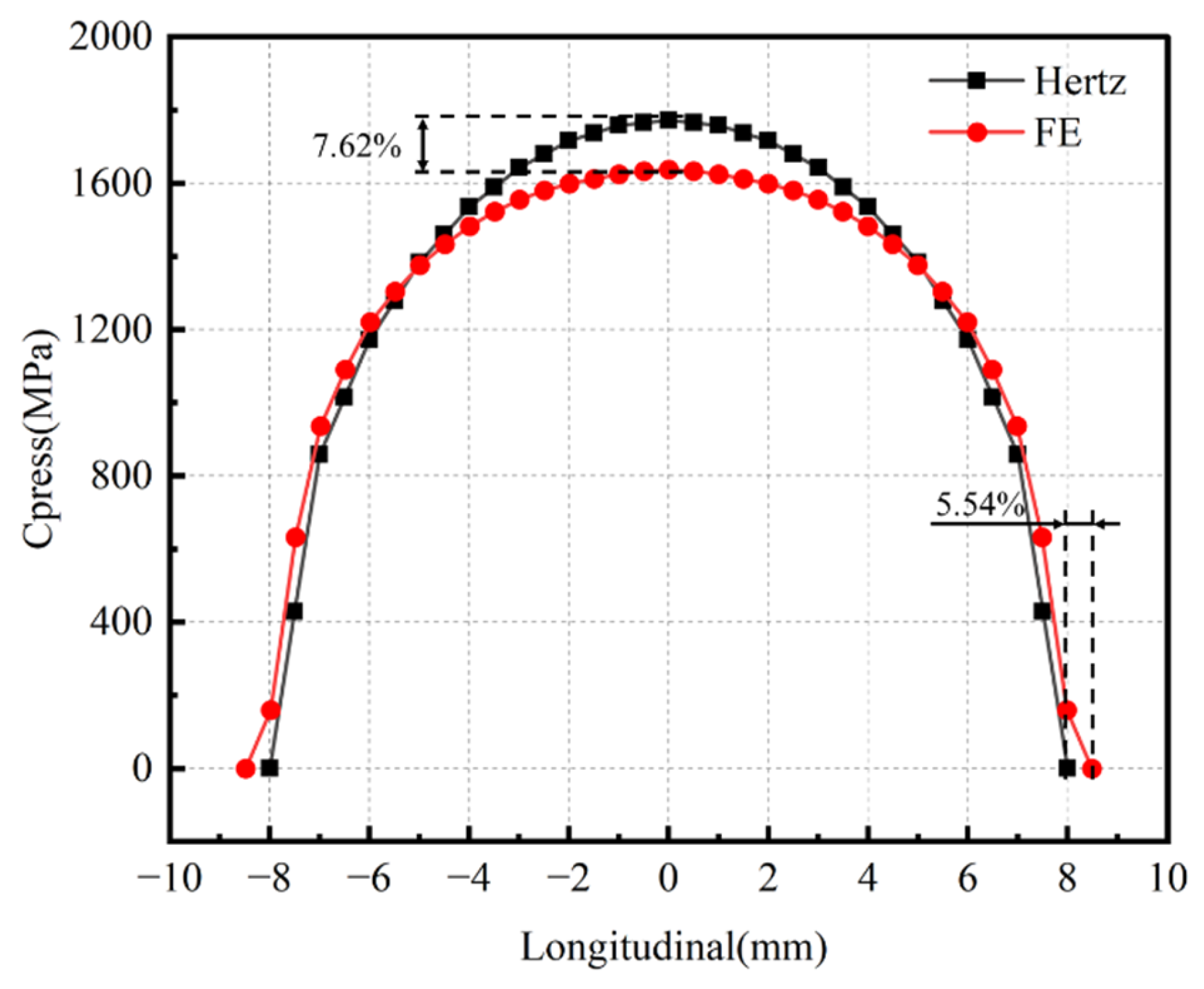
As shown in Figure 7, the long axis contact radius of the Hertz theoretical solution is 8.01 mm, while that of the finite element solution is 8.48 mm, the relative error is 5.54%. The maximum contact pressure of the tread obtained by the Hertz theory solution is 1772 MPa, and that obtained by the finite element solution is 1637 MPa, the relative error is 7.62%. The primary source of error stems from grid discretization. Due to the influence of grid discretization in the finite element model, the contact range obtained from the finite element analysis is slightly larger, which in turn results in a contact stress amplitude that is slightly smaller than the solution obtained from Hertz’s theory. Although there are some differences between the finite element solution and Hertz theory results, the finite element model and Hertz theory are basically consistent in the overall trend of contact solution, which is sufficient to reveal the trend of stress intensity factor changes and crack propagation behavior in subsequent research.
Figure 7.
Wheel–rail contact verification.
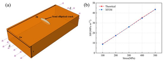
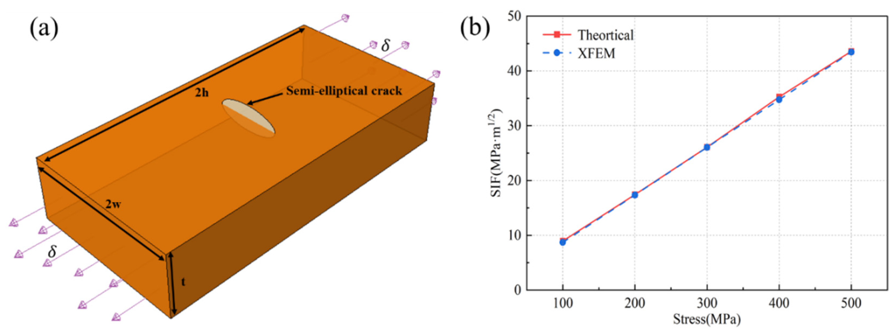
About the crack model, a large flat plate model is used to demonstrate the reliability of the established crack model and to verify that the chosen mesh size of 0.5 × 0.5 mm meets the computational accuracy. As shown in Figure 8a, the flat plate has a length of 2h = 100 mm, a width of 2w = 50 mm, a thickness of t = 20 mm, and each end of the flat plate is subjected to a tensile stress of δ MPa. The material of the flat plate is the same as the wheel material. There is a surface semi-elliptical crack in the center of the flat plate with crack length 2c = 20 mm, depth a = 4 mm, and crack depth–length ratio a/2c = 0.2. As shown in Figure 8b, the finite element solutions obtained by XFEM are compared with Newman-Raju’s solutions [43] under different stress fields. The results show that the finite element solution is within 5% relative error.
Figure 8.
Crack model verification: (a) Large flat plate with semi-elliptical surface cracks; (b) Comparison of SIF results.
2.4. Research Route
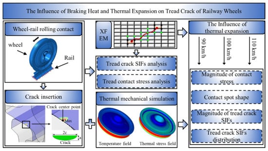
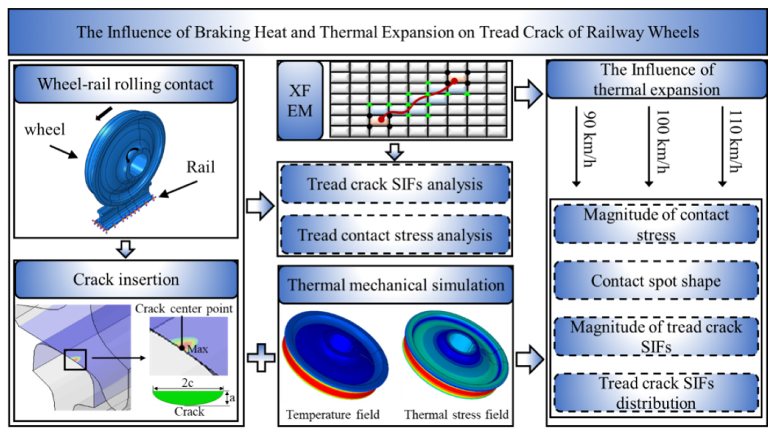
The technical flowchart of this work is shown in Figure 9. This study begins by establishing a finite element model of wheel–rail rolling contact, with a pre-defined crack at the location of maximum contact stress on the tread. Based on this model, the XFEM is employed to analyze the influence of the tread crack on wheel–rail contact behavior and cracking behavior. After that, the influence of braking heat and thermal expansion on the tread cracking behavior of railway wheels is analyzed.
Figure 9.
Technical flowchart of this work.
3. Results and Discussion
3.1. Tread Cracking Without the Consideration of Thermal Expansion
In order to have a better understanding of the influence of wheel thermal expansion on the cracking behavior of tread cracks, the tread cracking without considering the wheel’s thermal expansion should be analyzed first. The simulation is carried out under the condition of an axle load of 23.75 t and a speed of 90 km/h.
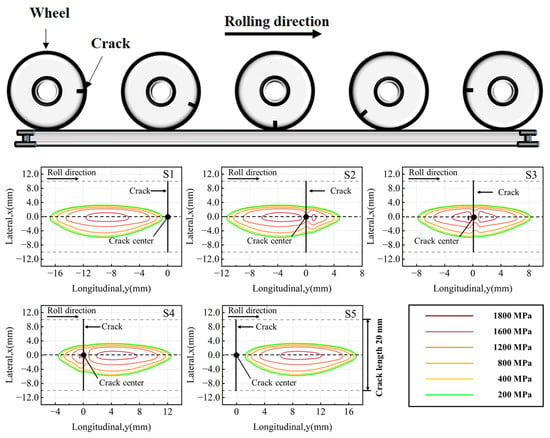
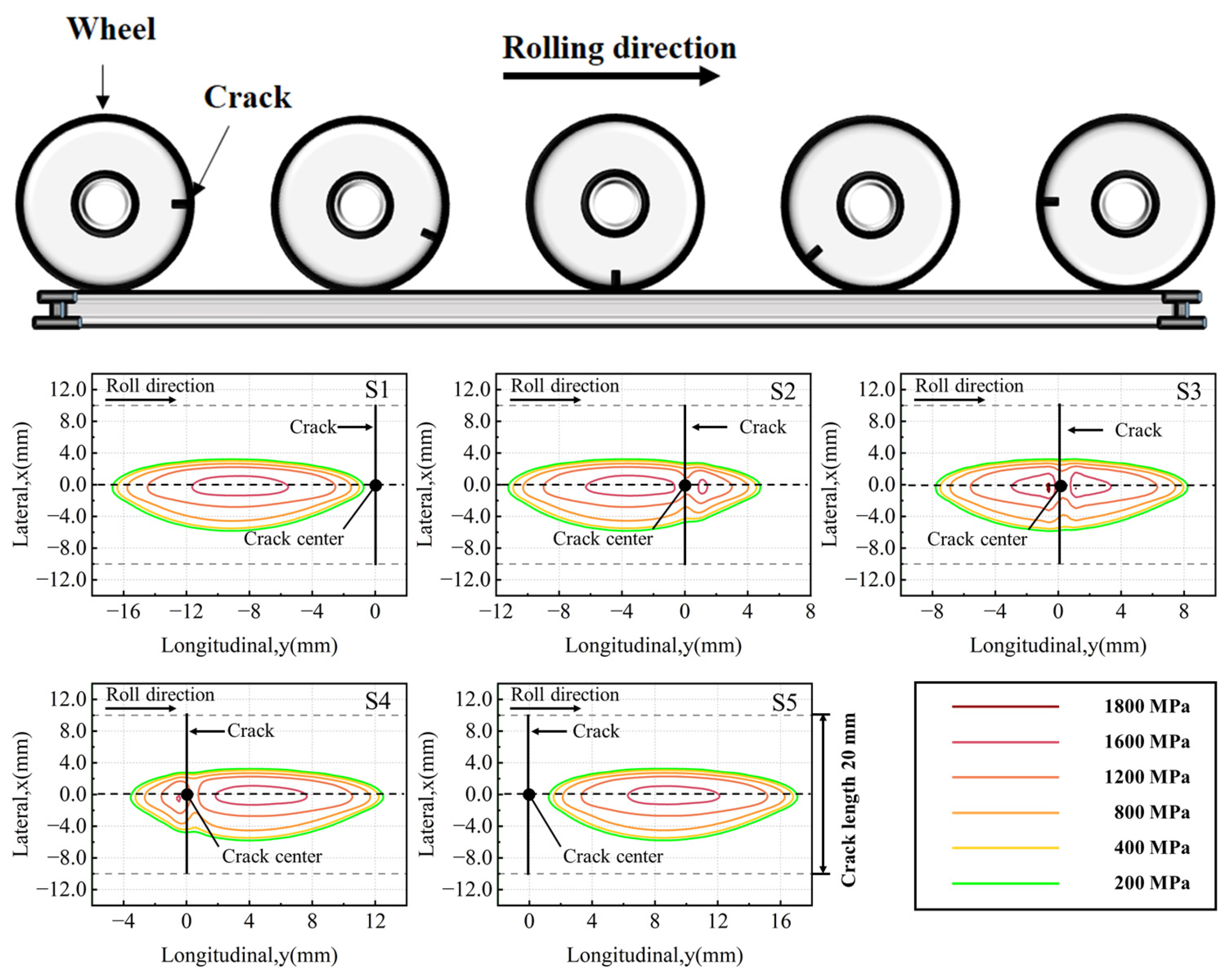
The study first investigates the influence of tread cracks on contact stress during wheel–rail rolling, analyzing the contact stress at five relative positions between the tread crack and contact spot. As shown in Figure 10, these five relative positions are defined as follows: contact spot approaching the crack (S1), contact spot contacting the crack (S2), center of contact spot coinciding with the crack (S3), center of contact spot moving away from the crack (S4), and contact spot leaving the crack (S5). A local coordinate system is established at the crack center, with the origin set at the center of the tread crack. The positive y-axis direction aligns with the running direction, while the x-axis represents the wheel axle direction, with its positive direction pointing toward the wheel rim.
Figure 10.
The relative positions between the contact spot and cracks.
As illustrated in Figure 11, the contact spot is oriented with its major axis parallel to the train’s running direction and its minor axis parallel to the crack, the latter being shorter than the crack length in this work. In the analysis of wheel–rail rolling contact, the relative spatial relationship between the contact spot and the tread crack significantly influences the contact stress distribution. When there is no overlap between the contact spot and the crack (conditions S1 and S5), the contact stress field exhibits a typical elliptical pattern, with its maximum value located at the center of the contact spot, consistent with the fundamental principles of Hertzian contact theory. However, when the crack is within the contact spot (conditions S2, S3, and S4), the contact mechanical behavior undergoes significant changes: the presence of the crack disrupts contact continuity, leading to a redistribution of the stress field. Specifically, the maximum contact stress increases significantly. Moreover, the contact stress distribution evolves from a single maximum point to a dual-peak pattern along both sides of the crack.
Figure 11.
The tread contact stress at five different positions.
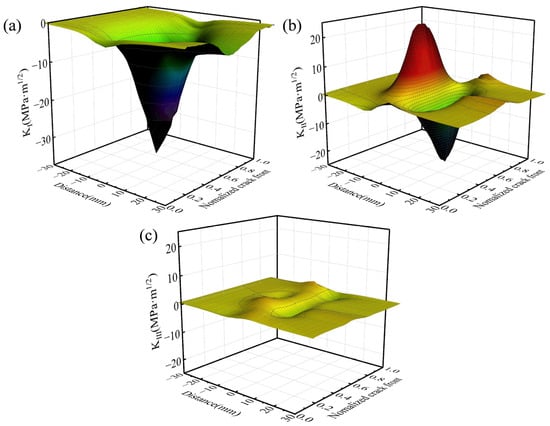
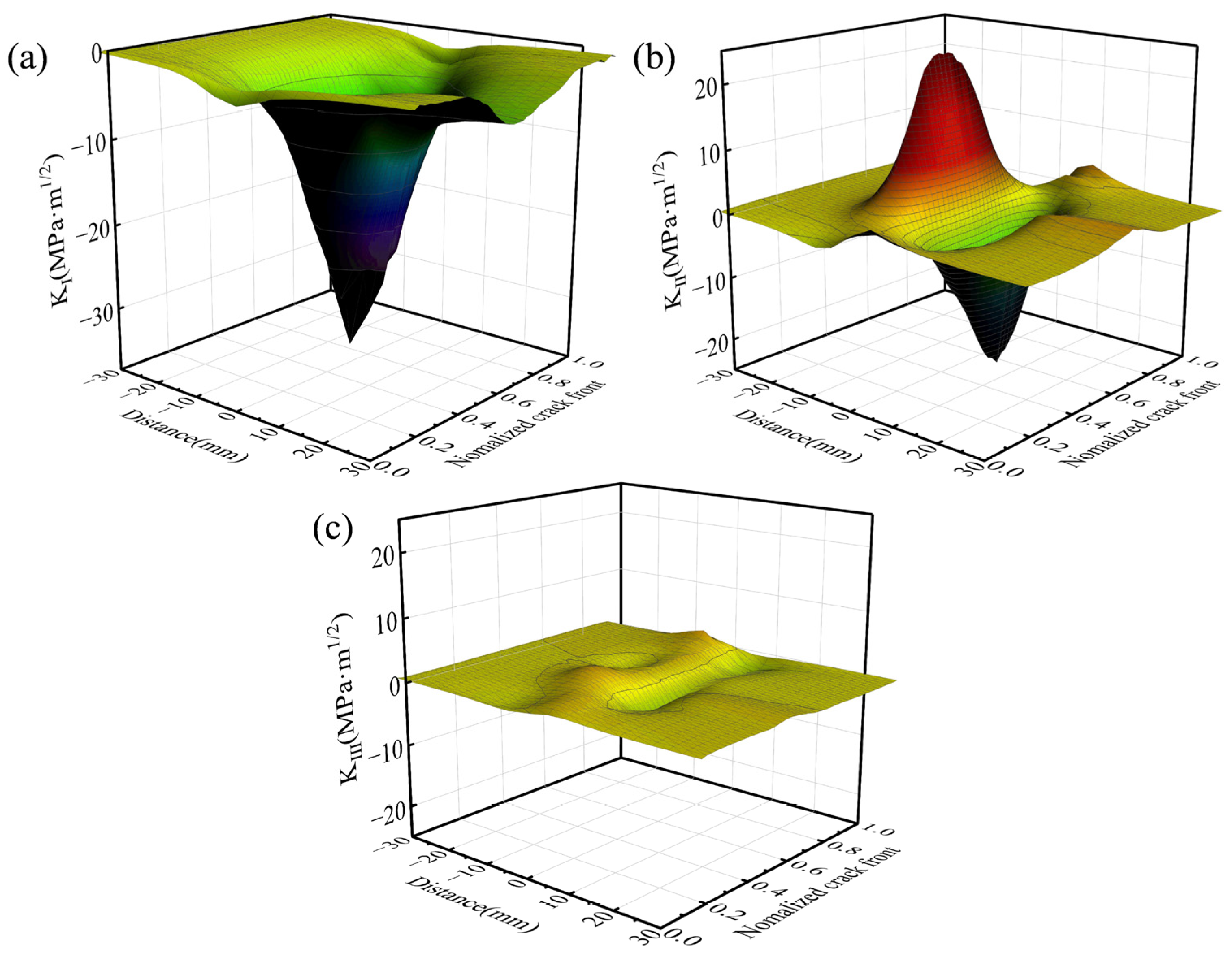
Figure 12 shows the stress intensity factor of the tread crack front during the wheel–rail rolling process. As shown in Figure 12a, the Mode I stress intensity factor for the tread crack is predominantly negative under wheel–rail rolling loads, indicating that the tread crack is under a compression state. As shown in Figure 12b, as the contact spot approaches the crack, the shear effect on the crack surface intensifies, leading to an increase in KII. When the center of the contact spot coincides with the crack, the shear action on the crack surface reaches a critical equilibrium state, and the KII reduces to 0. As the contact spot continues to move forward, the shear direction on the crack surface reverses, resulting in a sign reversal of KII and the emergence of a negative extreme value. Finally, when the contact spot completely moves away from the influence zone of the crack, the value of KII asymptotically returns to its initial state. Regarding Figure 12c, it can be seen that the value of the Mode III stress intensity factor is substantially lower than that of the Mode II stress intensity factor.
Figure 12.
Effect of wheel–rail rolling contact load on SIF: (a) SIF of Mode I; (b) SIF of Mode II; (c) SIF of Mode III.
The transient analysis of the crack tip stress intensity factors (KI, KII, KIII) has revealed the complex stress state at the crack tip during the wheel–rail rolling contact process. A deeper understanding of the crack growth behavior requires a shift from transient analysis to considering the entire cycle. Therefore, this study introduces the stress intensity factor range (ΔK) as a key parameter, defining the passage of the wheel over the crack as one cycle. This approach aims to characterize and evaluate the overall driving force for crack growth as the wheel rolls over the crack from the perspective of cyclic loading.
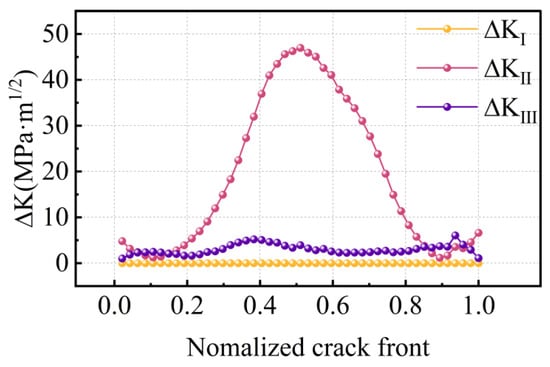
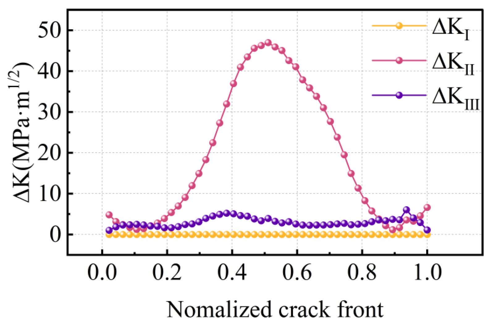
As shown in Figure 13, the Mode I stress intensity factor range (ΔKI) along the crack front is nearly zero. The distribution of ΔKII exhibits a trend of being higher in the middle and lower at the two ends, with its maximum value located at the deepest point of the crack. In contrast, ΔKIII is relatively uniform along the crack front, showing insignificant variation and remaining small in magnitude overall. These results indicate that the propagation of the tread crack during the wheel–rail rolling contact process is a mixed-mode propagation mechanism, predominantly governed by Mode II. The Mode II propagation is most pronounced in the central region of the crack, which is primarily because the shear force driving the Mode II propagation is supplied by the wheel–rail contact pressure: the central portion of the crack lies precisely within the contact spot area, subjecting it to intense shear stresses. Conversely, the two ends of the crack reside outside the contact spot, where the influence of the contact pressure is weak.
Figure 13.
Effect of wheel–rail rolling load on ΔK.
3.2. Tread Cracking with the Consideration of Thermal Expansion
Based on the results of the previous section, this section further considers the influence of braking heat and thermal expansion on tread cracking of railway wheels in different braking conditions. The emergency braking on the 25‰ ramp with different initial speed levels is adopted, the braking parameters are shown in Table 2.
Table 2.
Ramp emergency braking parameters.
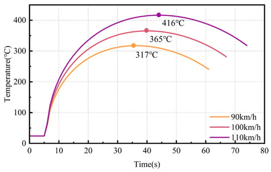
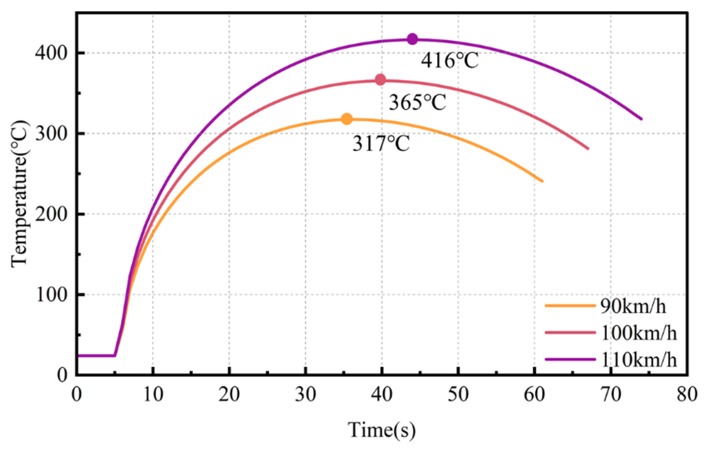
The wheel tread surface temperature variation during the braking process is shown in Figure 14. It can be seen that the rate of temperature rise gradually decreases before the tread temperature reaches its highest point. Afterwards, although the braking process continued, the tread temperature began to slowly decrease. The maximum temperature of the tread increases with the increase in the initial braking speed.
Figure 14.
Tread temperature curve.
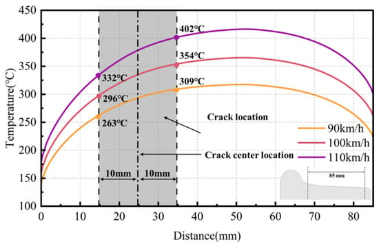
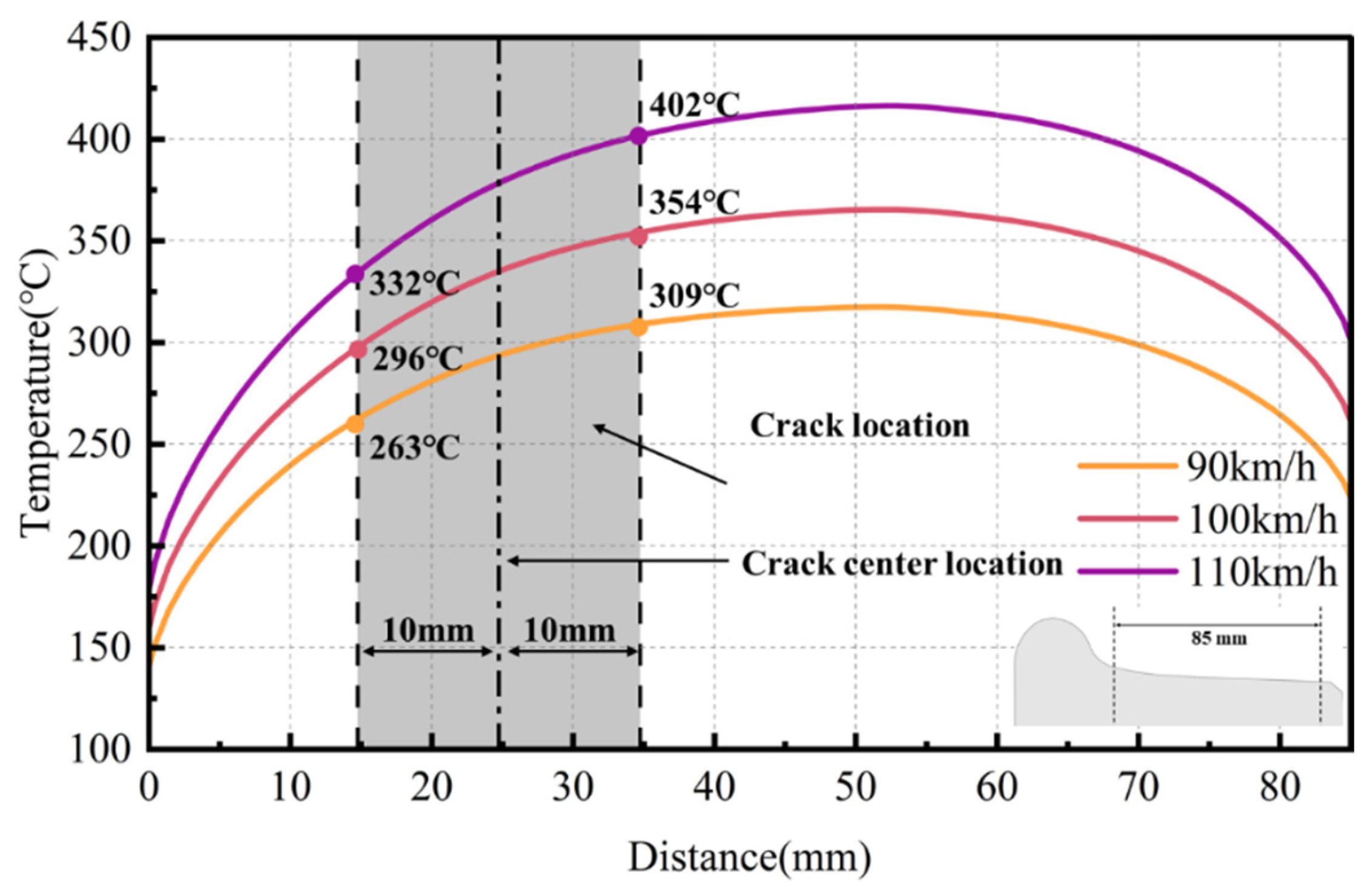
Figure 15 shows the tread temperature distribution curve along the axial direction of the wheel tread at the moment of the highest tread temperature. It can be observed that there is a significant temperature gradient on the wheel tread, with the outer region of the wheel tread (away from the wheel rim) exhibiting generally higher temperatures compared to the inner region (close to the wheel rim). Meanwhile, there is also a temperature difference between the inner and outer tips of the concerned tread crack. Because the location of the prefabricated crack is the point of maximum wheel–rail rolling contact stress at room temperature, the thermal expansion caused by the temperature distribution of the tread will inevitably lead to changes in the cracking behavior of the tread crack.
Figure 15.
Tread temperature distribution.
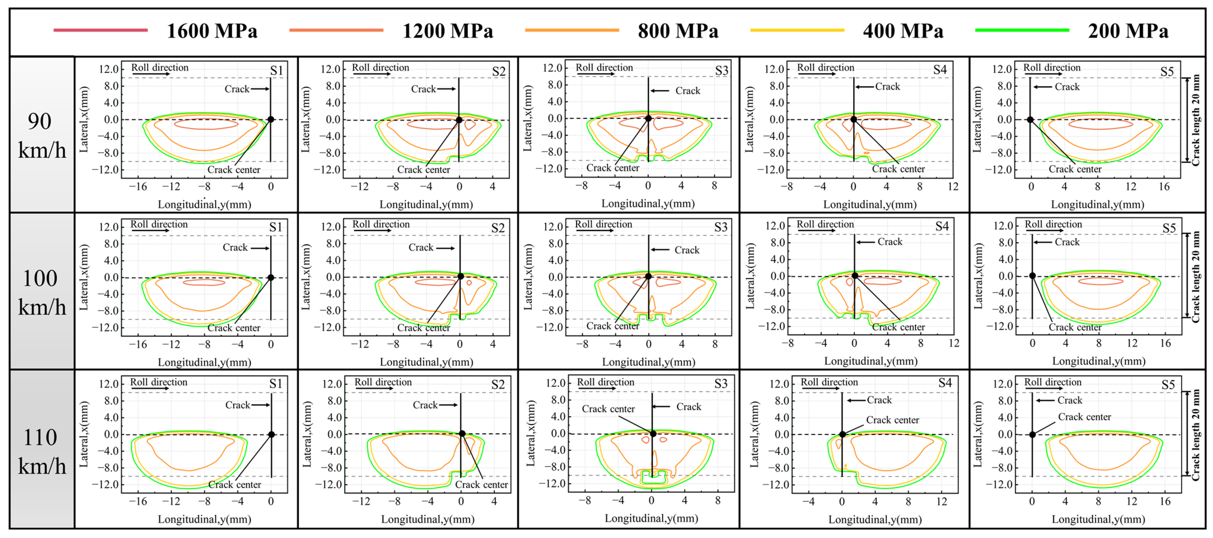
The distribution of rolling contact stress under different braking conditions at the highest temperature moment is shown in Figure 16. The results indicate that the thermal expansion effect induces significant morphological reconstruction of the tread contact spot, transitioning from a classical elliptical shape to a fan-shaped distribution. The wheel–rail contact spot moves away from the wheel rim, causing a change in the relative position between the center of the wheel–rail contact spot and the center of the crack. When the contact point covers the crack tip, the presence of the crack will disrupt the continuity of the contact, causing a redistribution of the stress field and forming a stress envelope around the crack tip. These phenomena can be attributed to the high-temperature softening of the material, which reduces the stress-bearing capacity of the tread area, and the change in tread profile caused by thermal expansion, which alters the contact boundary conditions.
Figure 16.
Influence of thermal expansion of wheel brake on the tread contact stress distribution of wheel with tread crack.
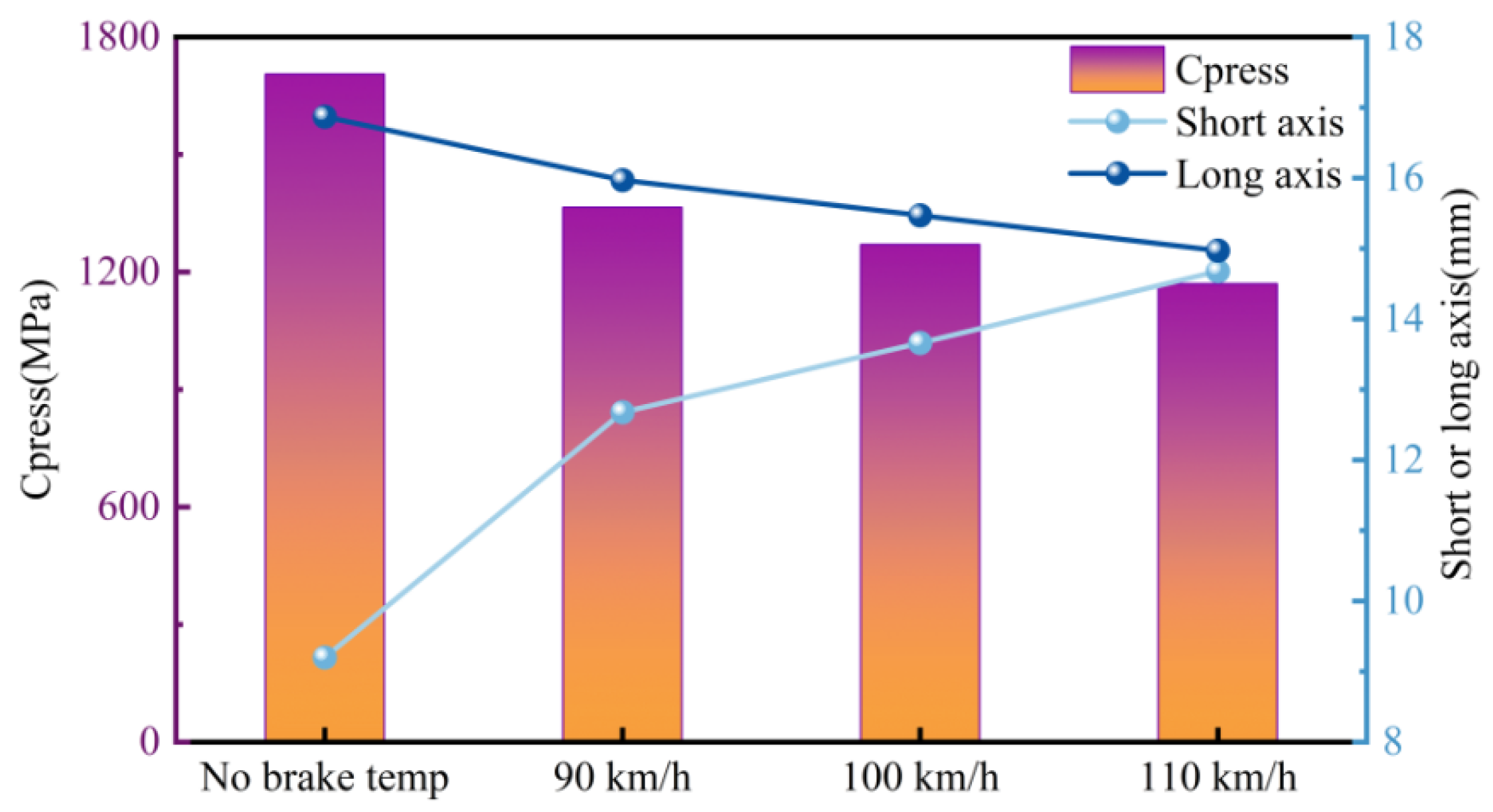
The quantitative analysis results of the contact state are shown in Figure 17. Specifically, the maximum contact stress and the long and short axes of the contact spot are selected to quantify the effect of thermal expansion. As shown in Figure 17, the maximum tread contact stress without considering thermal expansion is significantly higher than the corresponding values considering thermal expansion. This indicates that the increase in braking temperature is a key factor leading to the reduction in maximum contact stress. Regarding the contact spot morphology, as the braking temperature increases, the length of the minor axis of the contact spot increases, while the major axis length decreases. The response of the minor axis to temperature change is more pronounced. In summary, the increase in braking temperature causes a decrease in the maximum tread contact stress and makes the contact spot shape more rounded.
Figure 17.
Influence of wheel thermal expansion on tread contact characteristics.
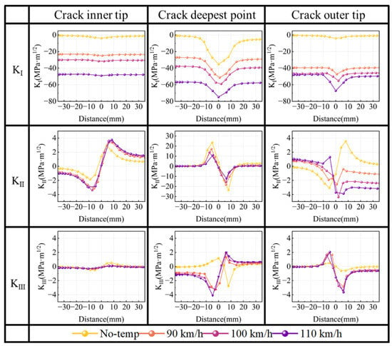
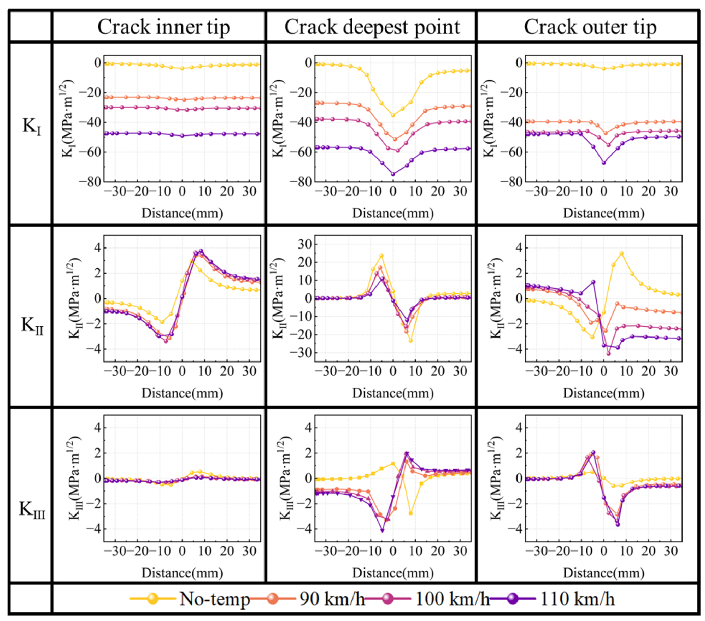
In order to investigate the effect of thermal expansion on the cracking behavior of tread cracks, three characteristic points are selected, which are the inner tip, the deepest point, and the outer tip of the crack (defined in Figure 6), to analyze and compare the changes in the stress intensity factor during wheel–rail rolling contact under different braking conditions at the highest temperature. As shown in Figure 18, under the condition without the consideration of wheel thermal expansion, the Mode I stress intensity factors (KI) at the crack inner tip and crack outer tip are close to zero, while KI at the deepest point is negative during the rolling process. When wheel thermal expansion is considered, KI values at all three characteristic points (inner tip, deepest point, and outer tip) are negative, and the absolute values increase with the initial braking speed. This is attributed to the circumferential compressive stress caused by wheel thermal expansion, and at the same time, the change in the contact configuration further enhances the closing behavior of cracks. Regarding the Mode II stress intensity factor (KII), its response exhibits a pronounced sine or cosine oscillation without the wheel thermal expansion. The extreme values of KII occur when the tread crack is located on either side of the contact spot center, with the most significant fluctuations observed at the deepest point. When wheel thermal expansion is considered, the magnitude of KII at the inner tip increases slightly, while the KII value at the deepest point slightly decreases. The KII values of the outer tip undergo complex variation under the influence of contact spots. For KIII, its magnitude is lower than that of KII. The crack inner tip is basically unaffected because it is far from the contact spot area. For the deepest point and outer tip, considering the thermal expansion, the amplitude of KIII increases.
Figure 18.
Influence of wheel thermal expansion on tread crack stress intensity factor during wheel–rail rolling contact.
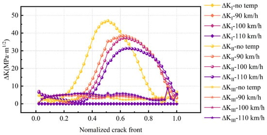
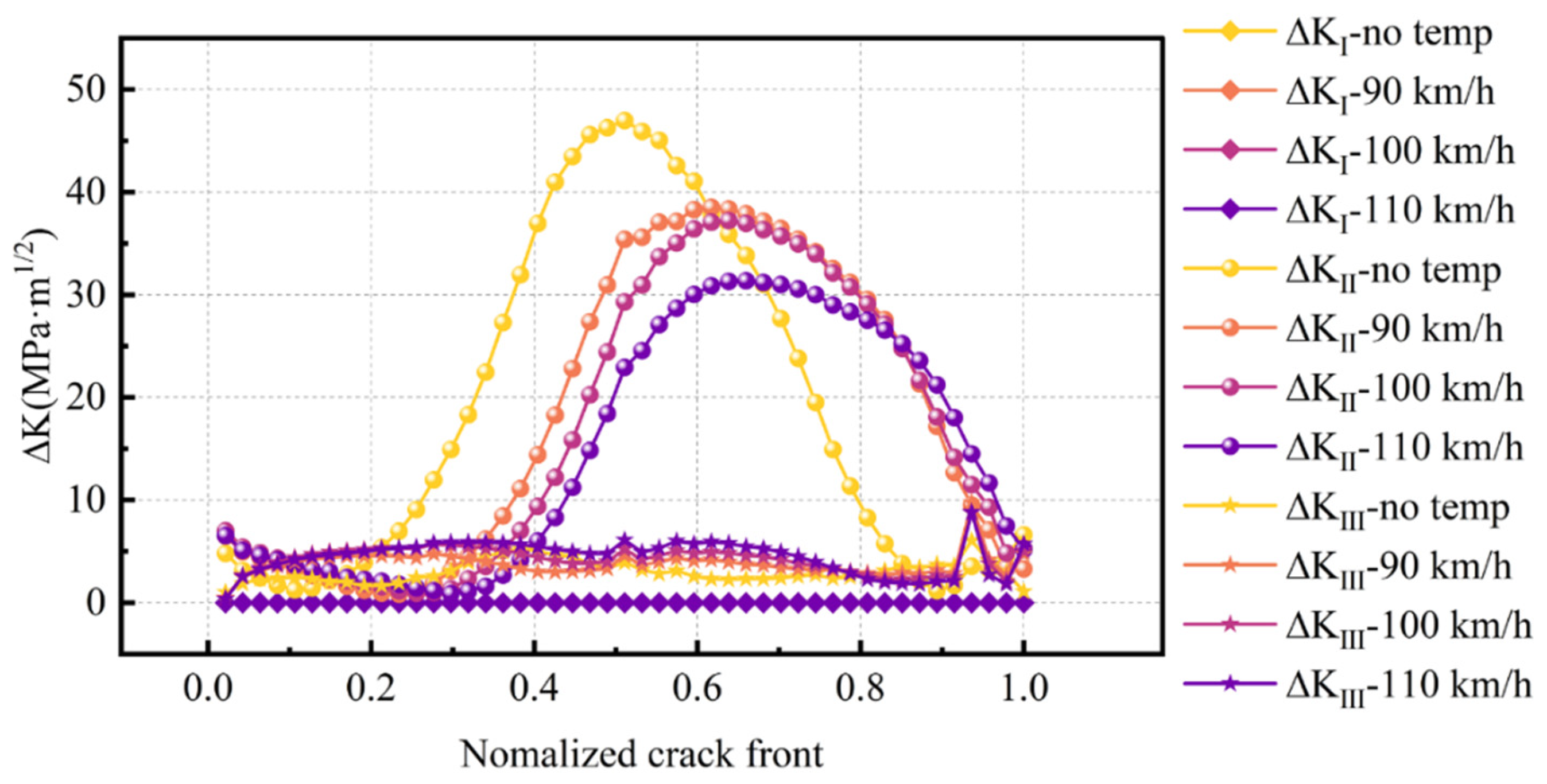
To analyze the propagation behavior of tread cracks more intuitively, Figure 19 shows the ΔK along the crack front during wheel–rail rolling. As shown in Figure 19, the influence of thermal expansion on ΔKI is negligible, indicating that the Mode I crack propagation mechanism remains inactive throughout the process. The effect of thermal expansion on ΔKIII is relatively weak, with its value increasing only slightly as the initial braking speed rises. In contrast, thermal expansion significantly alters both the distribution pattern and magnitude characteristics of ΔKII. Under the condition without wheel thermal expansion, the most severe Mode II propagation occurs in the crack’s deepest point region. When thermal expansion is considered, the peak value of ΔKII shifts from the deep region of the crack toward the crack outer tip, and the peak magnitude exhibits a decreasing trend as the initial braking speed increases. Because the outer tip region is closer to the wheel surface compared to the crack’s deepest region, although the maximum value of ΔKII decreases, the Mode II propagation in the crack region near the wheel surface becomes more severe. This phenomenon can be attributed to the combined action of material softening at elevated temperatures and the geometric alteration of the contact patch induced by thermal expansion. The softening of the material reduces the overall stress level, resulting in a decrease in the peak value of ΔKII. Simultaneously, thermal expansion can cause changes in the profile of the wheel tread, resulting in changes in the position and shape of the contact patch, thereby redistributing the stress at the crack front and making the region with the most intense crack growth move towards the surface. Generally speaking, existing research focuses on the behavior of tread crack propagation under residual stress conditions after braking and cooling [6,17]. However, the phenomenon of thermal expansion disappears as the temperature decreases after cooling. Therefore, this article analyzes the influence of the thermal expansion phenomenon under high braking temperature on the crack propagation behavior of the tread, which is an appropriate supplement to the study of tread thermal cracks.
Figure 19.
Influence of wheel thermal expansion on the distribution of K in the tread crack.
4. Conclusions
This article establishes a three-dimensional finite element model of wheel–rail rolling contact and combines the extended finite element method with thermal structure coupling analysis to systematically study the effect of braking heat and thermal expansion on the tread cracking behavior. Research has found that the combined effects of material softening and thermal expansion at high temperatures can reconstruct the stress field at the crack tip and alter the propagation behavior of tread cracks. The main conclusions are as follows:
- (a)
- During the rolling contact process without the consideration of braking heat, the tread cracks mainly exhibit multiaxial cracking behavior with Mode II cracking as the main mode, and the tread cracks mainly propagate along the crack depth direction rather than the crack length direction.
- (b)
- The braking heat changes the contact configuration by thermal expansion and material softening. Under the joint influence of these two factors, the shape of the contact spot expands from an elliptical shape to a fan-shaped one.
- (c)
- The driving force at the crack front will be reconstructed with the consideration of braking heat. The maximum ΔKII of the tread crack decreases, but the Mode II cracking near the wheel surface area becomes more severe. Although the nominal contact stress decreases when considering braking heat, the risk of surface-initiated damage increases, which needs to be paid attention to during operations and maintenance.
Author Contributions
Conceptualization, C.L. and J.M.M.-E.; methodology, C.L. and B.Y.; software, J.Z. and Z.Y.; validation, C.L., B.Y. and J.Z.; formal analysis, J.H.; investigation, J.Z.; resources, C.L.; data curation, J.Z. and J.H.; writing—original draft preparation, C.L.; writing—review and editing, C.L. and J.M.M.-E.; visualization, J.Z. and Z.Y.; supervision, C.L. and J.M.M.-E.; project administration, C.L.; funding acquisition, C.L. All authors have read and agreed to the published version of the manuscript.
Funding
The work is financially supported by the Natural Science Foundation of Sichuan Province (2025ZNSFSC0386) and the Fundamental Research Funds for the Central Universities (2682025GH009).
Data Availability Statement
The raw data supporting the conclusions of this article will be made available by the authors on request.
Conflicts of Interest
Author Bo Yuan was employed by the company CRRC Qiqihaer Rolling Stock Co., Ltd. The remaining authors declare that the research was conducted in the absence of any commercial or financial relationships that could be construed as a potential conflict of interest.
References
- Li, L.; Cai, Y.W.; Guo, G. Coupling effect of wheel-rail rolling contact and braking thermal load on crack initiation life of heavy haul wheel tread. China Railw. Sci. 2019, 40, 89–96. [Google Scholar]
- Vernersson, T.; Caprioli, S.; Kabo, E.; Hansson, H.; Ekberg, A. Wheel tread damage: A numerical study of railway wheel tread plasticity under thermomechanical loading. Proc. Inst. Mech. Eng. Part F J. Rail Rapid Transit 2010, 224, 435–443. [Google Scholar] [CrossRef] [Scilit]
- Nikas, D.; Ahlström, J.; Malakizadi, A. Mechanical properties and fatigue behaviour of railway wheel steels as influenced by mechanical and thermal loadings. Wear 2016, 366, 407–415. [Google Scholar] [CrossRef] [Scilit]
- Kato, T.; Kato, H.; Makino, T. Effect of elevated temperature on shelling property of railway wheel steel. Wear 2016, 366, 359–367. [Google Scholar] [CrossRef] [Scilit]
- Fang, X.Y.; Huang, W.; Yang, X.F.; Wang, J.G. Effects of temperature on fatigue cracks initiation and propagation for a high-speed railway wheel rim steel. Eng. Fail. Anal. 2020, 109, 104376. [Google Scholar] [CrossRef] [Scilit]
- Magel, E.E. Rolling Contact Fatigue: A Comprehensive Review; Centre for Surface Technology: Ottawa, ON, Canada, 2011. [Google Scholar]
- Walia, M.S.; Esmaeili, A.; Vernersson, T.; Lundén, R. Thermomechanical capacity of wheel treads at stop braking: A parametric study. Int. J. Fatigue 2018, 113, 407–416. [Google Scholar] [CrossRef] [Scilit]
- Landström, E.V.; Vernersson, T.; Lundén, R. Analysis and testing of tread braked railway wheel-Effects of hot spots on wheel performance. Int. J. Fatigue 2024, 180, 108116. [Google Scholar] [CrossRef] [Scilit]
- Liu, Y.; Tan, Z.; Tian, Y.; Zhu, J.; Zhang, M.; Zhang, M.; Zhao, H. Temperature-dependent crack induced by microstructure evolution in 20Mn2SiMoCuV bainite wheel steel. Eng. Fail. Anal. 2022, 140, 106593. [Google Scholar] [CrossRef] [Scilit]
- Esmaeili, A.; Walia, M.S.; Handa, K.; Ikeuchi, K.; Ekh, M.; Vernersson, T.; Ahlström, J. A methodology to predict thermomechanical cracking of railway wheel treads: From experiments to numerical predictions. Int. J. Fatigue 2017, 105, 71–85. [Google Scholar] [CrossRef] [Scilit]
- Chandak, N.; Yede, M.; Malviya, P.; Pradhan, M. Analysis of railway wheel to study crack initiation due to thermal loading and calculating life cycle. Mater. Today Proc. 2017, 4, 2454–2463. [Google Scholar] [CrossRef] [Scilit]
- Ekberg, A.; Sotkovszki, P. Anisotropy and rolling contact fatigue of railway wheels. Int. J. Fatigue 2001, 23, 29–43. [Google Scholar] [CrossRef] [Scilit]
- Shen, M.; Yan, C.; Bai, Z.; Gong, F.; Li, C.; Li, Q. Comparative study on wear and fatigue behaviors of rail steels with varying levels of martensite and bainite under rolling-sliding contact conditions. Wear 2025, 560, 205594. [Google Scholar]
- Karttunen, K.; Kabo, E.; Ekberg, A. Numerical assessment of the influence of worn wheel tread geometry on rail and wheel deterioration. Wear 2014, 317, 77–91. [Google Scholar] [CrossRef] [Scilit]
- Zhang, S.; Liu, Q.; Spiryagin, M.; Wu, Q.; Ding, H.; Wen, Z.; Wang, W. Gaps, challenges and possible solution for prediction of wheel-rail rolling contact fatigue crack initiation. Railw. Eng. Sci. 2023, 31, 207–232. [Google Scholar]
- Maglio, M.; Vernersson, T.; Nielsen, J.C.O.; Ekberg, A.; Kabo, E. Influence of railway wheel tread damage on wheel-rail impact loads and the durability of wheelsets. Railw. Eng. Sci. 2024, 32, 20–35. [Google Scholar]
- Caprioli, S. Short rolling contact fatigue and thermal cracks under frictional rolling-A comparison through simulations. Eng. Fract. Mech. 2015, 141, 260–273. [Google Scholar] [CrossRef] [Scilit]
- Kato, T.; Yamamoto, Y.; Kato, H.; Dedmon, S.; Pilch, J. Effect of fracture toughness on vertical split rim failure in railway wheels. Eng. Fract. Mech. 2017, 186, 255–267. [Google Scholar] [CrossRef] [Scilit]
- Canadinc, D.; Sehitoglu, H.; Verzal, K. Analysis of surface crack growth under rolling contact fatigue. Int. J. Fatigue 2008, 30, 1678–1689. [Google Scholar] [CrossRef] [Scilit]
- Liu, Z.K.; Shang, S.L.; Wang, Y. Fundamentals of thermal expansion and thermal contraction. Materials 2017, 10, 410. [Google Scholar] [CrossRef] [Scilit]
- Ren, Q.; Wang, L.; Huang, Q. A Micro-test structure for the thermal expansion coefficient of metal materials. Micromachines 2017, 8, 70. [Google Scholar] [CrossRef] [Scilit]
- Vasiljevic, S.; Glišović, J.; Stojanovic, B.; Stojanovic, N.; Grujic, I. The analysis of the influential parameters that cause particles formation during the braking process: A review. Proc. Inst. Mech. Eng. Part J J. Eng. Tribol. 2022, 236, 31–48. [Google Scholar] [CrossRef] [Scilit]
- Brkić, R.; Adamović, Ž.; Bukvić, M. Modeling of reliability and availability of data transmission in railway system. Adv. Eng. Lett. 2022, 1, 136–141. [Google Scholar] [CrossRef] [Scilit]
- Chen, X.; Lu, C.; Liu, X.; Sun, T.; Mo, J. The influence of competition between thermal expansion and braking parameter on the wear degradation of friction block. Tribol. Int. 2024, 192, 109246. [Google Scholar] [CrossRef] [Scilit]
- Wei, Y.; Han, J.; Yang, T.; Wu, Y.; Chen, Z. Research on wheel/rail contact surface temperature and damage characteristics during sliding contact of a wheel. J. Eng. Appl. Sci. 2024, 71, 201. [Google Scholar] [CrossRef] [Scilit]
- He, J.; Lu, C.; Zhao, J.; Ye, Z.; Martínez-Esnaola, J.M. Analysis of railway wheel tread cracking under the combined action of brake thermal load and wheel-rail rolling contact. Eng. Fail. Anal. 2026, 185, 110389. [Google Scholar] [CrossRef] [Scilit]
- Handa, K.; Kimura, Y.; Mishima, Y. Surface cracks initiation on carbon steel railway wheels under concurrent load of continuous rolling contact and cyclic frictional heat. Wear 2010, 268, 50–58. [Google Scholar] [CrossRef] [Scilit]
- Caprioli, S.; Vernersson, T.; Handa, K.; Ikeuchi, K. Thermal cracking of railway wheels: Towards experimental validation. Tribol. Int. 2016, 94, 409–420. [Google Scholar] [CrossRef] [Scilit]
- Song, J.; Huang, X.; Wang, S.; Xie, G.; Dong, Y. Fatigue life prediction of brake treads for C80 trains with long downhill cycles. J. Jilin Univ. 2025, 55, 866–876. [Google Scholar]
- He, C.; Zou, G.; Liu, H.; Wang, X.; Xu, Y.; Liu, J.; Lo, S. Rolling–sliding wear and damage behaviors of 304L stainless steel laser cladding on a damaged wheel tread under high ambient temperature conditions. Wear 2024, 546, 205330. [Google Scholar] [CrossRef] [Scilit]
- Handa, K.; Ikeuchi, K.; Morimoto, F. Temperature-dependent wear of tread-braked railway wheels. Wear 2020, 452, 203265. [Google Scholar] [CrossRef] [Scilit]
- Zhang, P.; Wen, Z.F.; Wu, L. Temperature and stress field analysis of wheel tread braking process using different heat flux loading modes. Lubr. Eng. 2013, 38, 69–74. [Google Scholar]
- TB/T 3463-2016; Railway Vehicle Wheel Strength Assessment Method. China Railway Publishing House: Beijing, China, 2016.
- TB/T 1047.1-2018; Train Traction Calculations Part I: Locomotive Drawn Trains. China Railway Publishing House: Beijing, China, 2018.
- Sukumar, N.; Srolovitz, D.J. Extended finite element method for three-dimensional crack modelling. Int. J. Numer. Methods Eng. 2000, 48, 1549–1570. [Google Scholar] [CrossRef] [Scilit]
- Irwin, G.R. Analysis of stresses and strains near the end of a crack traversing a plate. J. Appl. Mech. 1957, 24, 361–364. [Google Scholar] [CrossRef] [Scilit]
- Irwin, G.R. Fracturing and Fracture Mechanics; Department of Theoretical and Applied Mechanics, College of Engineering, University of Illinois at Urbana-Champaign: Urbana, IL, USA, 1961. [Google Scholar]
- Irwin, G.R. Crack-extension force for a part-through crack in a plate. J. Appl. Mech. 1962, 29, 651–654. [Google Scholar] [CrossRef] [Scilit]
- Deuce, R. Wheel Tread Damage—An Elementary Guide; Bombardier Transportation GmbH: Netphen, Germany, 2007. [Google Scholar]
- Zhao, X.; Wen, Z.; Wang, H.; Tao, G.; Jin, X. Research progress on wheel/rail rolling contact fatigue of rail transit in China. J. Traffic Transp. Eng. 2021, 21, 1–35. [Google Scholar]
- Zhao, X.; Li, Z.L. The solution of frictional wheel–rail rolling contact with a 3D transient finite element model: Validation and error analysis. Wear 2011, 271, 444–452. [Google Scholar] [CrossRef] [Scilit]
- Hertz, H. Ueber die Berührung fester elastischer Körper. J. Reine Angew. Math. 1882, 92, 156–171. [Google Scholar] [CrossRef] [Scilit]
- Newman, J.C.; Raju, I.S. An empirical stress-intensity factor equation for the surface crack. Eng. Fract. Mech. 1981, 16, 185–192. [Google Scholar] [CrossRef] [Scilit]



Disclaimer/Publisher’s Note: The statements, opinions and data contained in all publications are solely those of the individual author(s) and contributor(s) and not of MDPI and/or the editor(s). MDPI and/or the editor(s) disclaim responsibility for any injury to people or property resulting from any ideas, methods, instructions or products referred to in the content. |
© 2026 by the authors. Licensee MDPI, Basel, Switzerland. This article is an open access article distributed under the terms and conditions of the Creative Commons Attribution (CC BY) license.