


Abstract
As a critical component of demolition robots, the rotary joint supports the entire manipulator arm and operates under severe loading conditions, rendering it highly susceptible to fatigue failure. To address this challenge, topology optimization is integrated into the structural design to simultaneously enhance fatigue life and achieve lightweighting. In this work, multiple working conditions of the demolition robot are considered and analyzed to identify the extreme operating condition. By extracting the resultant stress on the rotary joint from the assembled structure under the extreme condition, an equivalent model of the independent rotary joint is established. Given that topology optimization based on the original structure could not yield a usable structure, two topology optimization strategies based on resetting the design space are proposed, including topology optimization based on the partially filled design space and topology optimization within the fully filled design space. By performing topology optimization under different schemes, the optimized rotary joint models are reconstructed through geometric fusion. Numerical results demonstrate that the optimized rotary joints exhibit significant improvements in fatigue performance, with fatigue life doubled compared to the original design. Concurrently, the structural mass is effectively reduced. This proposed method achieves the dual objectives of fatigue life enhancement and lightweight design. Furthermore, the results reveal that resetting the design space when topology optimization fails to obtain a usable structure yields superior topology optimization outcomes, providing a valuable new insight for future structural optimization design processes in similar engineering scenarios.
1. Introduction
In recent years, demolition robots have attracted extensive attention and application in hazardous environments such as metallurgy, mining, nuclear facility decommissioning, and building demolition [1,2,3]. These robots can replace manual operations in dangerous or hard-to-reach areas, providing higher safety and demolition efficiency [4,5,6]. Being the most critical component of the demolition robot, the rotary joint connects the base and the manipulator arm. It must withstand the impact force transmitted from the hydraulic breaker, the lateral force generated by material manipulation, and the gravity of the manipulator itself. Its structural performance directly affects the overall performance, working efficiency, and reliability of the demolition robot. However, current rotary joint designs often suffer from limited fatigue life, excessive weight, and low material utilization, which restrict the service life and working capability of the robot [7]. Therefore, a redesign of the rotary joint is necessary to enhance its fatigue life while reducing its mass. However, traditional structural design approaches are generally based on market feedback and designer experience to optimize structural performance. Although these methods may improve local strength to a certain extent, they often fail to enhance the global structural performance or the fully stressed material utilization [8,9,10].
The topology optimization (TO) has attracted both attentions from both academic and industry owing to its capability to generate structures with high strength to density ratios [11,12,13,14]. Compared to traditional TO approaches, the stress-constrained TO holds great practical significance in engineering applications [15]. This is because the stress-constrained TO method can avoid local stress concentrations, which lead to fatigue damage or structural failure [16]. Consequently, this method has been found to be extremely useful in fields such as aerospace, automotive manufacturing, and architectural engineering [17,18,19]. For the perspective of engineering applications, strength index is paramount [20]. TO offers significant advantages in the structural design of industrial robots [21]. Through multi-objective optimization design of robots, their initial and operating costs can be effectively reduced [22]. Addressing complex dynamic working conditions and global performance requirements, scholars have significantly enhanced the dynamic accuracy and adaptability of robots and effectively reduced joint driving torques by employing methods such as topological superposition, global workspace optimization, and the introduction of time-varying inertial loads [7,23,24,25]. Regarding critical stress constraints, relevant studies have achieved multiple optimizations in sensing sensitivity, structural safety, and boundary smoothness by constructing robust models, introducing geometric nonlinearity, and adopting isogeometric analysis [26,27,28].
In this work, the stress-driven TO method is applied to the rotary joint, aiming to simultaneously prolong structural fatigue life and achieve a lightweight design. Through global optimization of material distribution, this approach ensures the reliability and durability of the structure while effectively reducing the mass of the rotary component. The study focuses on the anode-demolition robot used in aluminum electrolysis, and rotary joint models with partially filled and fully filled design spaces are established, respectively, to conduct research on two TO strategies. Finite element analysis (FEA) is conducted on the rotary joint under severe loading conditions, and the variable density TO method is adopted to optimize the design of the rotary joint. By comparing the results of the two optimization strategies, the advantages and limitations of each approach are identified, providing valuable reference for selecting the most effective design strategy.
2. Analysis of Typical Working Conditions
2.1. Determination of Loads and Working Conditions
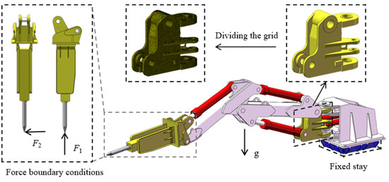
The demolition robot is a robot used to break the anode white materials in aluminum electrolysis, which features high motion performance requirements and complex structural characteristics. The structural compositions of the robot are illustrated in Figure 1, together with the two typical working conditions, i.e., vertical and horizontal loads. When the robot is in operation, each segment of the manipulator arm is driven by the hydraulic system to complete various functional actions. Among them, the rotary joint, as a key component connecting the arm frame and the base, needs to drive the entire manipulator arm to swing, bearing the vertical and horizontal reaction forces generated during demolition and turning, as well as the gravity of the manipulator itself [29].
Figure 1.
Simplified model of the demolition robot, two boundary conditions, and meshing of the rotary joint.
Then typical working conditions of the demolition robot are modeled and analyzed to obtain the distribution of the stress in the demolition robot under the extreme working condition during practical engineering operation, which provides the necessary data foundation for obtaining the resultant stress at each hinge joint of the rotary joint under extreme conditions in subsequent analyses.
In the demolition process, the piston rod of the hydraulic breaker periodically experiences a normal impact reaction force F1 from the working surface, as shown in Figure 1. This reaction force is transmitted through the breaker to the joints and structural members of the manipulator, with a periodicity equal to that of the breaker operation. Additionally, during practical operation, the demolition robot must rotate the aluminum anode using the manipulator arm, which results in a lateral reaction force F2, as shown in Figure 1.
According to the law of action and reaction, this impact force can be estimated from the impact energy of the hydraulic breaker. Since the elastic modulus of the initial prebaked anode is 5.5 GPa and the generated inhomogeneous anode residue ranges from 2 GPa to 4 GPa, both of which are far smaller than the 220 GPa elastic modulus of structural steel, the deformation mainly occurs in the anode residue, allowing for a simplified calculation. Given that the breaker’s single impact energy is 785 J and the piston stroke is 75 mm, the impact reaction force is calculated as F1 = 10.47 kN. Then we assuming that the rod tip rotates the anode to the left, the process can be approximately equivalent to rotating a rectangular column in the vertical plane. Given the approximate mass m = 2000 kg and the friction coefficient between the anode and the ground μ = 0.35, the maximum static friction force can be calculated as Ff = 6.86 kN. When the applied force reaches 6.86 kN, the anode begins to rotate, and at this moment, the tip of the hydraulic breaker rod is subjected to an equal and opposite reaction force directed to the right, F2 = 6.86 kN. Considering load fluctuations during breaking and rotating, by multiplying by a safety factor of 1.8, the equivalent lateral reaction force applied to the rod tip during analysis is F1′ = 18.85 kN, F2′ = 12.35 kN. During the demolition process, the F1′ and F2′ have the large torque when manipulator arm reaches its maximum travel position which is chosen for the later calculation.
2.2. Establishment and Analysis of the Finite Element Model
To ensure computational efficiency and the accuracy of FEA, the model can be simplified based on the principle of equivalent stiffness. The simplified model removing components such as hydraulic assemblies, pipelines, fittings, and ferrules are removed and minor structural features such as fillets, chamfers, process edges, and threaded holes are filled or smoothed is used [30,31], as shown in Figure 1. Then the global mesh adopts solid elements, primarily tetrahedral meshes, with refined meshing applied to contact regions, and the maximum element size of the obtained global model is 1.69% of the structural size, with the meshing results of the rotary joint shown in Figure 1. Later, for the demolition robot made of structural steel, the corresponding material properties are listed in Table 1.
Table 1.
Material properties of structural steel.
The lower part of the base embedded in the foundation is defined as a fixed support, and the gravitational acceleration is applied vertically downward to the entire robot, as illustrated in Figure 1. The manipulator arms and hydraulic cylinders of the demolition robot are connected through pins and bushings, while different pin-bushing pairs operate under varying lubrication conditions. In high-fidelity modeling, to simulate the poor lubrication or wear state of the pin-bushing throughout the full life cycle, all hinge contact surfaces are modeled as frictional contacts with a coefficient of friction μ = 0.2 [30,32]. The equivalent impact reaction force F1′ and the equivalent lateral reaction force F2′ at the extreme position are applied as force boundary conditions, and the boundary conditions for these two loading cases are shown in Figure 1.
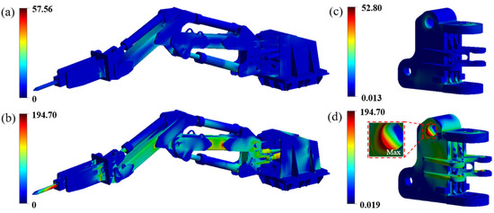
The equivalent stress contour plots for normal force and lateral force are shown in Figure 2a and Figure 2b, respectively. From the equivalent stress distribution contours, it can be observed that the maximum equivalent stresses throughout the robot are all lower than the allowable stress of structural steel. Under normal force loading, the maximum equivalent stress occurs at the junction between the boss of the boom’s lower hinge hole and the reinforcing rib. The equivalent stress contour of the rotary joint under this loading condition is shown in Figure 2c, and the maximum equivalent stress is located at the intersection between the lower hinge hole and the bottom plate of the rotary joint. Under lateral force loading, the maximum equivalent stress appears at the intersection between the upper hinge hole of the rotary joint and its side surface, as shown in Figure 2d.
Figure 2.
Equivalent stress contour plots under two loading conditions: (a) global equivalent stress contour plot under normal force loading; (b) global equivalent stress contour plot under lateral force loading; (c) equivalent stress contour plot of the rotary joint under normal force loading; (d) equivalent stress contour plot of the rotary joint under lateral force loading.
It can be concluded that under lateral force loading, the overall load on the robot is significantly greater than that under normal force loading. This indicates that the load acting on the rotary joint is also much higher than in normal force loading. Therefore, lateral force loading is identified as the extreme working condition during the operational cycle of the demolition robot’s rotary joint. The boundary conditions corresponding to this working condition are used for the subsequent analysis and optimization design of the rotary joint, and the results obtained under this condition can satisfy the other working conditions encountered during the robot’s operation.
3. Establishment and Analysis of the Equivalent Model of the Rotary Joint
Based on the previous analysis of multiple typical working conditions of the demolition robot, the extreme working condition has been determined. Here, an equivalent model of the rotary joint is independently established. The resultant stresses at each hinged joint of the rotary joint under this condition are extracted and applied as force boundary conditions to the corresponding positions on the independent rotary joint. The rotary joint is then analyzed separately for its stress distribution and fatigue life.
3.1. Establishment of the Equivalent Model
The model of the overall demolition robot involves nonlinear contacts and a large number of nodes. Performing TO directly on the rotary joint within the assembly environment would not only be computationally intensive but also prone to singularities [32]. Therefore, the rotary joint must be modeled independently before TO.
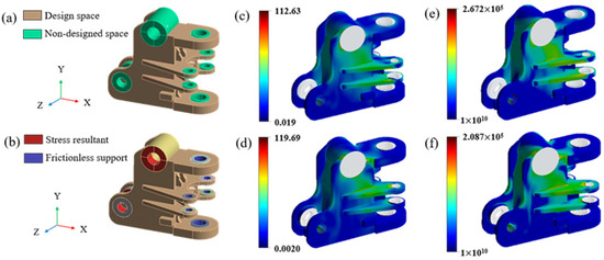
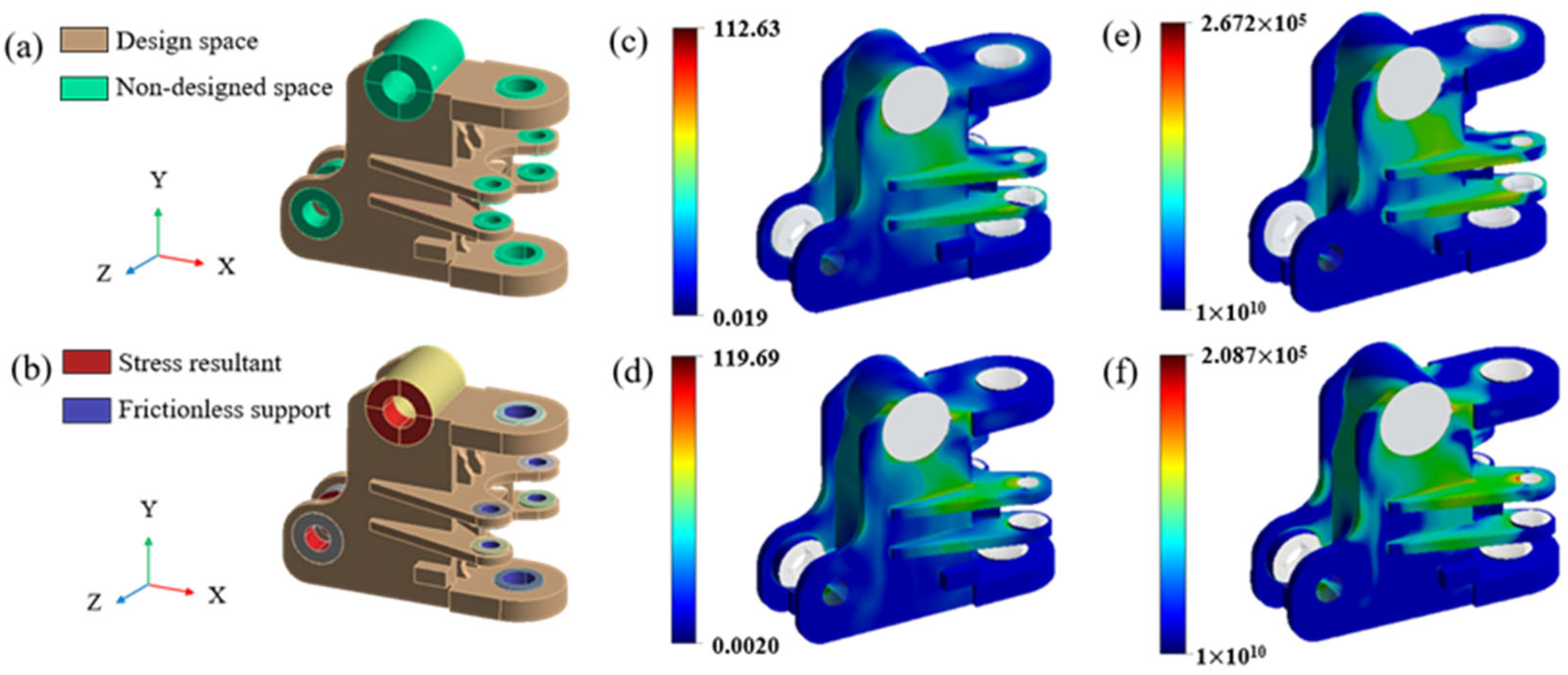
Boundary conditions need to be applied to the hinged regions of the independent rotary joint; meanwhile, to ensure reliable connections in the hinged regions after optimization, the rotary joint is divided into a design space and a non-design space as shown in Figure 3a, with no TO performed on the non-design space. Regarding the application of boundary conditions for the independent model, the force distribution on the hinged contact surfaces of the rotary joint is highly non-uniform due to the lateral force and the gravity of the manipulator arm, affecting the load transmission path of the design space. Consequently, to simulate this non-uniform loading, the contact surfaces are refined when extracting the resultant stress of the hinged contact surfaces. Since the rotary joint is in a state of equilibrium, only the resultant stress of the contact surfaces connecting the rotary joint and the manipulator arm need to be extracted. Thus, these contact surfaces are uniformly divided into 32 geometric surfaces, and the nodal forces on each geometric surface are integrated to obtain the resultant stress force, and the resultant stress components in the Cartesian coordinate system are extracted.
Figure 3.
Division of the design space, setting of boundary conditions, and contour plots of analysis results for the rotary joint: (a) division of the design space; (b) setting of boundary conditions; (c) stress contour of the design space from the overall analysis; (d) stress contour of the design space from the independent analysis; (e) fatigue life contour of the design space from the overall analysis; (f) stress contour of the design space from the independent analysis.
The resultant stress components extracted above are applied sequentially to the corresponding positions on the independent rotary joint, while the hinged contact surfaces between the rotary joint and the fixed housing are set as frictionless supports. The boundary conditions are shown in Figure 3b. The material of the rotary joint is structural steel, and its material properties are shown in Table 1.
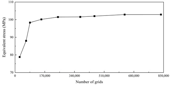
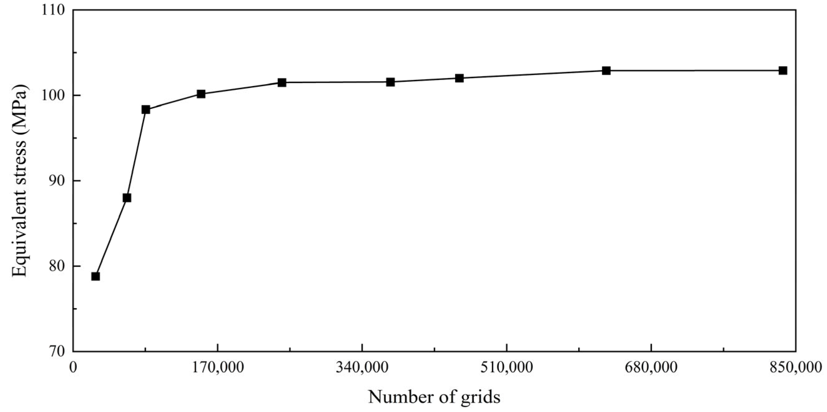
The independent rotary joint model is meshed. The global mesh adopts solid elements, primarily tetrahedral elements. As shown in Figure 4, nine sets of finite element models with different mesh densities were established, and the equivalent stress values at the same point for each model were extracted and compared. When the mesh was further refined, at a mesh count of 373,282, the variation in the stress of the structure tended to stabilize with a difference of no more than 2%, indicating that the solution had achieved mesh convergence. Finally, the determined element size is 0.62% of the overall structural dimensions.
Figure 4.
Mesh convergence for equivalent stress.
Based on the above boundary conditions, FEA is carried out, and the equivalent stress and fatigue life distributions are obtained. Since TO is performed only on the design space, it is only necessary to verify whether the stress distribution in the design space of the independent rotary joint is equivalent to that in the assembly. The equivalent stress contour of the rotary joint from the independent analysis is shown in Figure 3d, with a maximum stress of 119.69 MPa. Compared with the equivalent stress contour of the rotary joint design space obtained from the overall analysis of the demolition robot in Figure 3c, the load transfer paths are identical, and the maximum stress differs by only 7.06 MPa from that of the overall analysis, 112.63 MPa, resulting in an error of merely 6.27%. Since the maximum stresses in both cases appear at the connection between the upper hinged platform surface and the main body, it can be considered that the stress conditions are the same. In addition, the fatigue life distributions shown in Figure 3e,f are identical, and the minimum life is slightly lower than the value from the overall analysis, making the design more conservative. Therefore, the equivalent model is established.
3.2. Initial Fatigue Life Analysis
The rotary joint is repeatedly subjected to lateral and normal impact loads during operation, resulting in periodic variations of internal stress, which easily leads to fatigue failure [33]. It can be seen from the above analysis that the stress acting on the rotary joint during operation is lower than its yield strength, and the material remains within the range of linear elastic deformation, where stress fatigue usually occurs [34]. Therefore, the S-N curve method is adopted in this study to predict the fatigue life.
Meanwhile, the complex configuration of the rotary joint and the impact caused by stress concentration at the welds are also considered. According to the fitting of the stress amplitude σa = 252.67 MPa at N = 104 and σa = 81.41 MPa at N = 106 and other data in a logarithm coordinate system for the actual structural steel welded joint, the material based corrected S-N curve can be obtained [35,36,37,38,39,40,41]. The corrected S-N curve is expressed in the Basquin form, where the fatigue strength coefficient is σf′ = 2885.922 MPa, and the fatigue strength exponent is b = −0.246. Accordingly, the corrected S-N curve of the structural steel material is given as:
Fatigue analysis is performed after the static analysis results of the independent rotary joint. Since the manipulator arm causes the rotary joint to experience a symmetric cyclic alternating load while rotating the aluminum anode, a fully reversed load with a proportional factor of 1 is applied. Meanwhile, since the gravity acting on the rotary joint introduces a constant static stress component, forming a static stress bias and resulting in a stress ratio that is not strictly −1, to consider the effect of mean stress, the Goodman mean stress theory is applied to analyze the fatigue life of the rotary joint after correction [42]. Simultaneously, one cycle period is defined as the manipulator arm completing one left-and-right pushing motion to reset the anode.
Based on the fatigue life distribution of the rotary joint, it can be seen that the minimum fatigue life occurs at the connection between the upper hinged platform surface and the main body, with about 2.087 × 10⁵ cycles. The fatigue life at the connection between the rotary cylinder hinged platform surface and the main body is also only 3.225 × 10⁵ cycles, these two locations are the most likely to experience fatigue failure. Therefore, optimization design of the rotary joint is needed to optimize the load transfer path, improve the local fatigue life, and enhance the overall service life of the component.
4. Rotary Joint Topology Optimization Design
4.1. Topology Optimization Based on the Variable Density Method
The rotary joint of the demolition robot is a continuous structure and can be optimized using the solid isotropic material with penalization (SIMP) method to lead to an optimal value for certain structural metrics, such as volume and mass [7,43]. Meanwhile, stress constraints are added to reduce the maximum stress value and improve its fatigue life [44,45]. This method assumes that the material density is variable, changing between 0 and 1 to simulate material removal and retention. By establishing the relationship between material properties and element density, with element density as the design variable and structural strain energy as the optimization objective, the mathematical model for TO is constructed [46]. The mathematical model can be represented as
where x is the design variable, i.e., the relative density of the element; n is the total number of design area elements; C is the structural compliance; F is the nodal load vector; U is the nodal displacement vector; K is the global stiffness matrix; E0, Emin are the maximum and minimum material elastic moduli, respectively; p is the penalty factor, set to p = 3 in this model; ui is the nodal displacement vector for the i-th element; k0 is the stiffness matrix of the base element; V is the total volume of the current design structure; vi is the volume of the i-th element in the design area; f is the set volume fraction of the final optimized model; V0 is the initial total volume of the model; V∗ is the set upper volume limit of the optimized model. N is the total number of elements involved in stress computation; σvM,j(x) is the Von Mises equivalent stress of the j-th element; σallow is the set Von Mises stress constraint; q is the exponent of the aggregation function, set to q = 6 in this model; xmin is the lower bound for the element relative density, set to xmin = 1.0 × 10⁻³ in this model.
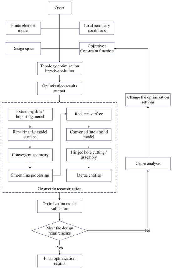
In this paper, based on the above SIMP TO theory, the TO design of the rotary joint is performed after FEA. The optimization design process is shown in Figure 5. After completing FEA and TO, the design model is no longer based solely on geometric data but is represented as the optimal solution in the form of solid elements. Therefore, a specialized surface-smoothing method is required to smooth such fractal surface solutions, accurately identify the external surface of the object, and convert the shape optimization data into a geometry-based CAD model. The solid model is then reanalyzed through FEA to verify the reliability of the design [9,47].
Figure 5.
Topology optimization process.
According to the reverse engineering technique, geometric reconstruction is performed on the data obtained after TO, as shown in the geometric reconstruction section of Figure 5. The TO result model is extracted in the form of triangular element node coordinates, and the obtained point cloud data are used as the input file [47].The imported surface model is repaired to fix issues such as missing parts, overlaps, mesh defects, and sharp corners. Then, disconnected small facets are separated and deleted. Subsequently, geometry shrinking is performed to remove sharp spike surfaces and generate uniform triangular facets. After surface smoothing, the number of facets is reduced. Finally, the processed surface model is converted into a solid model. The hinged holes of the solid model are trimmed, assembled with the solid model of the non-design space part, and then merged into a single solid through Boolean operations to complete the geometric reconstruction.
4.2. Topology Optimization Design Based on the Original Model
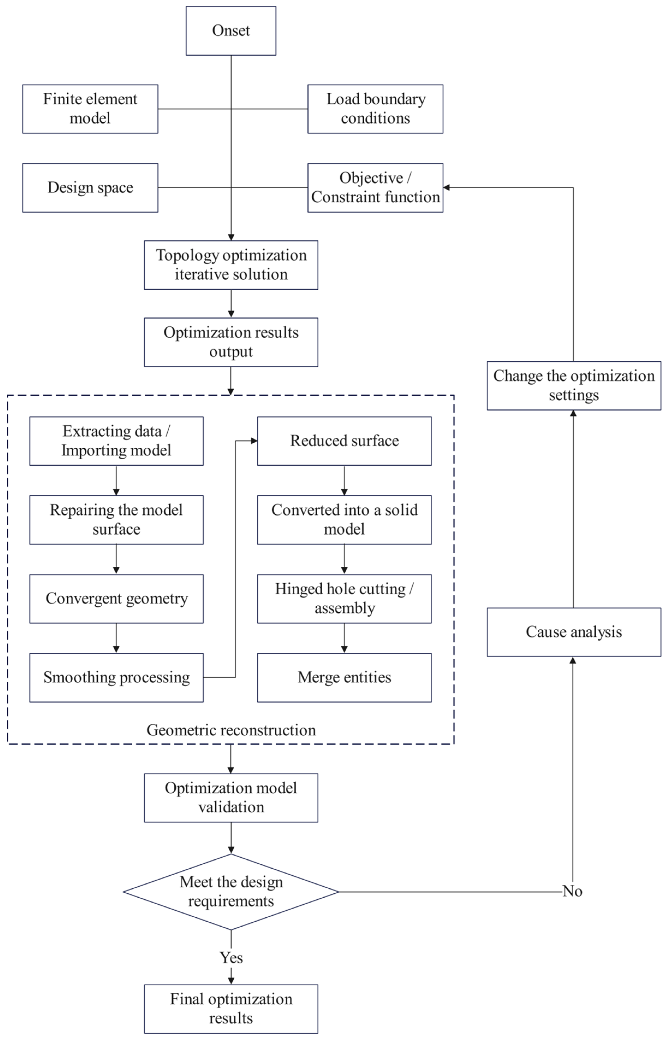
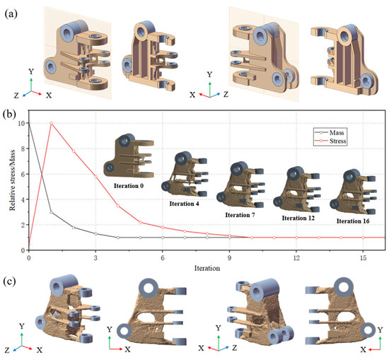
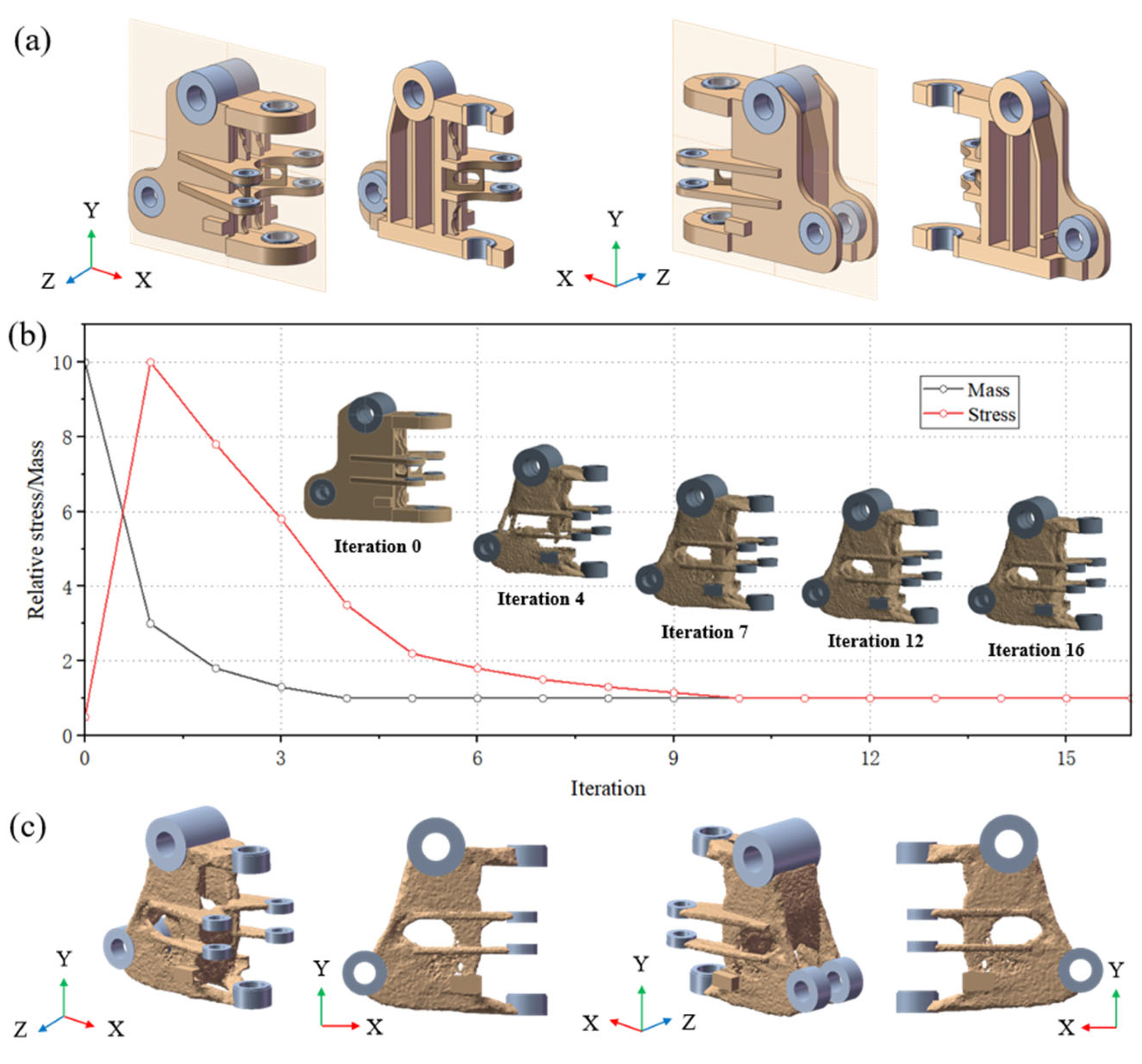
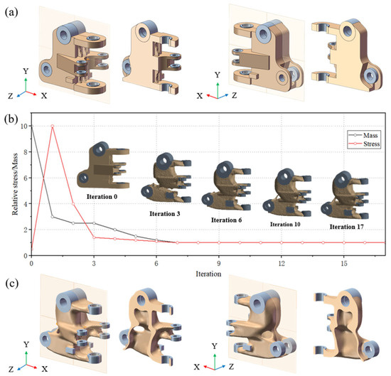
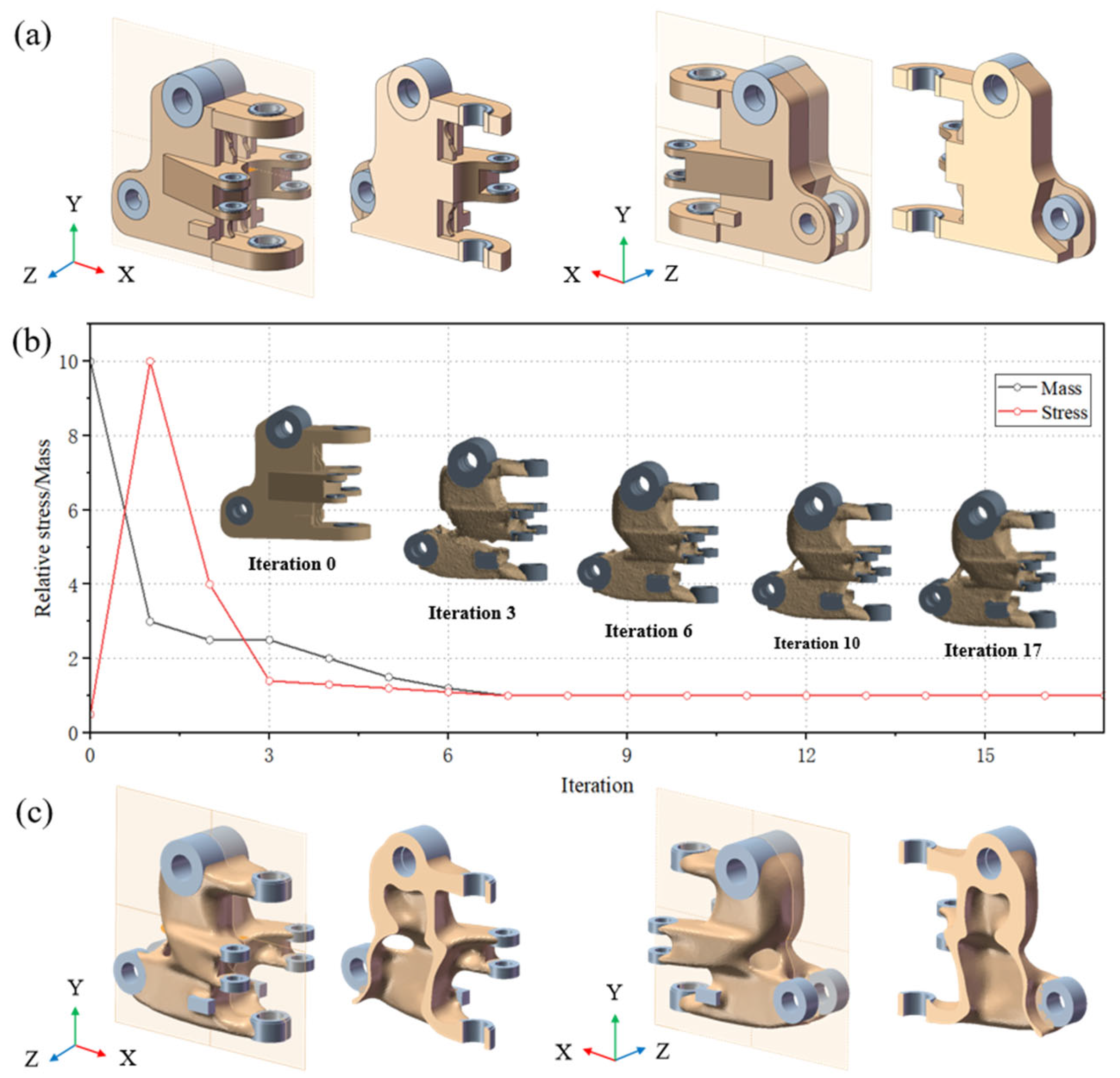
The original rotary joint structure is shown in Figure 6a. After performing FEA on the independent rotary joint, the design space of the rotary joint is subjected to TO. During the optimization process, the constraint conditions are set as follows: a mass response constraint to retain 40% of the original mass, and a stress response constraint with stress ≤ 250 MPa. In the SIMP TO model, these constraints are expressed as f = 0.4 and σallow = 250 MPa. In addition, a symmetric design constraint is applied on the XOY plane of the rotary joint. The above constraints are used to adjust the solving strategy of the SIMP TO model, in order to obtain appropriate hollow structures and dimensions, while ensuring that the optimized result of the component remains symmetric about the XOY plane.
Figure 6.
Topology optimization of original rotary joint: (a) axonometric view of the structure before optimization; (b) evolution of the topological structure with corresponding variations in stress and mass; (c) axonometric view of the optimized topological structure.
After 16 iterations of optimization, the convergence accuracy reaches 0.1%. The evolution of the topological structure is shown in Figure 6b. The result of the 16th iteration is adopted as the final topology structure as shown in Figure 6c for geometric reconstruction. It is observed that the optimal structure obtained under such relaxed stress constraints exhibits large-scale voids between the supporting plates. Furthermore, surface defects are prone to occur during the reconstruction process, making it difficult to implement the reconstruction and impossible to achieve the goal of improving fatigue life.
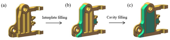
The results of TO performed based on the original model are unsatisfactory. The limited design space defined by the original model affected the outcome of the TO to some extent [9]. To reduce this influence, the original model was gradually filled to change the design space, thereby obtaining better optimization results. As shown in Figure 7, without affecting the fit between the rotary joint and other components, the spaces between the supporting plates and the internal cavities of the rotary joint were gradually filled to change the design space for TO.
Figure 7.
Stepwise filling of rotary joint model: (a) the original model; (b) interplate filling model; (c) completely filled model.
4.3. Topology Optimization Design Based on the Inter-Plate Filled Model
Firstly, based on the original model as shown in Figure 7a, the spaces between the plates were filled to expand the inter-plate design space as much as possible, obtaining the filled model as shown in Figure 7b. Subsequently, the design and non-design spaces were defined. The non-design space of the filled model is the same as that shown in Figure 3a, while all other regions are defined as design space.
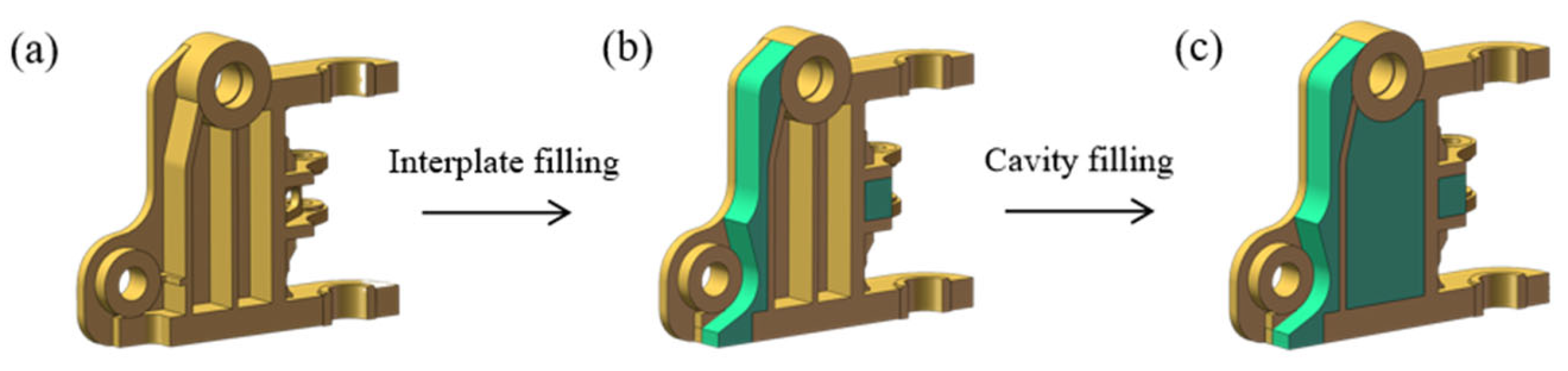
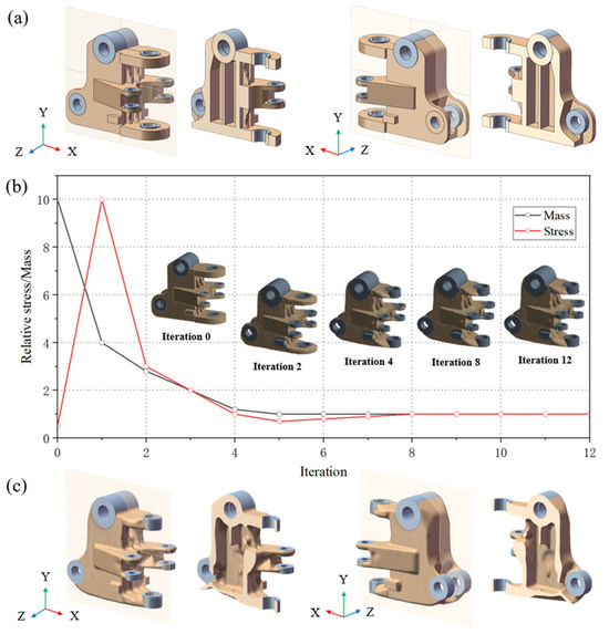
The specific structure of the filled rotary joint is shown in Figure 8a. Boundary conditions as shown in Figure 3b are applied to the rotary joint. After performing FEA, the design space of the rotary joint is subjected to TO. During the optimization process, the constraint conditions are set as follows: a mass response constraint to retain 75% of the original mass, and a stress response constraint with stress ≤ 90 MPa. In the SIMP TO model, these constraints are expressed as f = 0.75 and σallow = 90 MPa. In addition, a symmetric design constraint is applied on the XOY plane of the rotary joint, and a minimum element size constraint of 30 mm is applied to the entire design space. The above constraints are used to adjust the solving strategy of the SIMP TO model, in order to obtain appropriate hollow structures and dimensions, while ensuring that the optimized result of the component remains symmetric about the XOY plane.
Figure 8.
Topology optimization of inter-plate filled rotary joint: (a) axonometric view of the structure before optimization; (b) evolution of the topological structure with corresponding variations in stress and mass; (c) axonometric view of the geometrically reconstructed structure.
After 12 iterations of optimization, the convergence accuracy reaches 0.1%. The evolution of the topological structure is shown in Figure 8b, and the result of the 12th iteration is adopted as the final topology structure for geometric reconstruction and further study.
According to the geometric reconstruction process shown in Figure 5, by fixing the imported surface, wrapping using a shrink geometry with a gap size of 2 mm, performing smoothing with an angle threshold of 180°, and reducing triangular facets with parameters of a maximum deviation of 0.5 mm and a reduction ratio of 60%. The above parameters are used to control requirements such as fillets and curvature of the structure after geometric reconstruction. Finally, trimming the hinged holes and merging other parts. The reconstructed structure of the rotary joint is shown in Figure 8c. The mass of the reconstructed rotary joint is 368.94 kg, compared with 391.34 kg before optimization, achieving a weight reduction of 22.4 kg, thus realizing the goal of lightweight design.
4.4. Topology Optimization Design Based on Full Filling Model
Based on the inter-plate filled model as shown in Figure 7b, the internal cavities were further filled to achieve the maximum design space, obtaining the fully filled model as shown in Figure 7c. Subsequently, the design and non-design spaces are set. The non-design space of the filled model is the same as that shown in Figure 3a, while other regions are defined as design space.
The specific structure of the filled rotary joint is shown in Figure 9a. The boundary conditions shown in Figure 3b were applied to the rotary joint. After performing FEA, the design space of the rotary joint was subjected to TO. During the optimization process, the constraint conditions were set as a mass response constraint retaining 50% of the mass and a stress response constraint of σ ≤ 120 MPa, corresponding to f = 0.5 and σallow = 120 MPa in the SIMP TO model. At the same time, a symmetry design constraint was applied on the XOY plane of the rotary joint, and a manufacturing constraint with a minimum element size of 40 mm was set. These constraints were used to adjust the solution strategy of the SIMP TO model to obtain better hollow shapes and dimensions, while ensuring that the optimization result of the component remained symmetric about the XOY plane.
Figure 9.
Topology optimization of fully filled rotary joint: (a) axonometric view of the structure before optimization; (b) evolution of the topological structure with corresponding variations in stress and mass; (c) axonometric view of the geometrically reconstructed structure.
After 17 iterations of optimization, the optimization result satisfied the convergence accuracy of 0.1%. The evolution of the topological structure and the variations in mass and stress are shown in Figure 9b. The 17th iteration optimization result was finally adopted, and this topological structure was used for geometric reconstruction and subsequent research.
After the TO was completed, the model was expressed in terms of material density. According to the geometric reconstruction process shown in Figure 5, operations were performed by fixing the imported surface, wrapping using a shrink geometry with a gap size of 2 mm, performing smoothing with an angle threshold of 180°, and reducing triangular facets with parameters of a maximum deviation of 0.5 mm and a reduction ratio of 60%. The above parameters were used to control requirements such as fillets and curvature of the structure after geometric reconstruction. Finally, the hinged holes were trimmed and other parts were merged. The reconstructed structure of the rotary joint is shown in Figure 9c. The mass of the reconstructed rotary joint was 344.00 kg, which is 47.34 kg lighter than the rotary joint before optimization, 391.34 kg, representing a weight reduction ratio of 12.10%, thereby achieving the goal of lightweight design.
4.5. Analysis of Topology Optimization Results
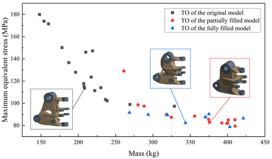
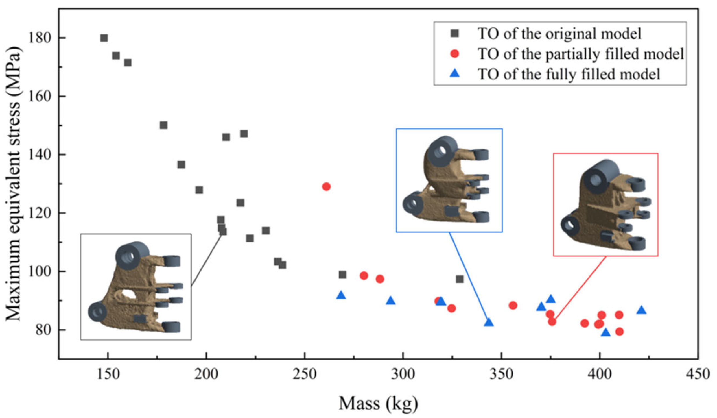
The different combinations of volume fraction, stress constraints, and symmetry constraints are considered. Then the optimization outcomes are summarized as shown in Figure 10. It can be clearly observed that the selected results lie on the Pareto frontier of the mass-stress trade-off. The final determinations of the optimal solution as shown in Figure 10 are chosen on the Pareto frontier by further considering practical manufacturing constraints thus ensuring that the selected scheme balances both theoretical optimality and engineering applicability and used for fatigue analysis.
Figure 10.
The relationship between the structural mass and Von Mises stress of different optimization results.
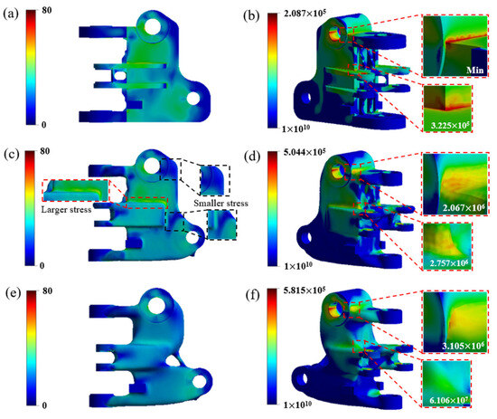
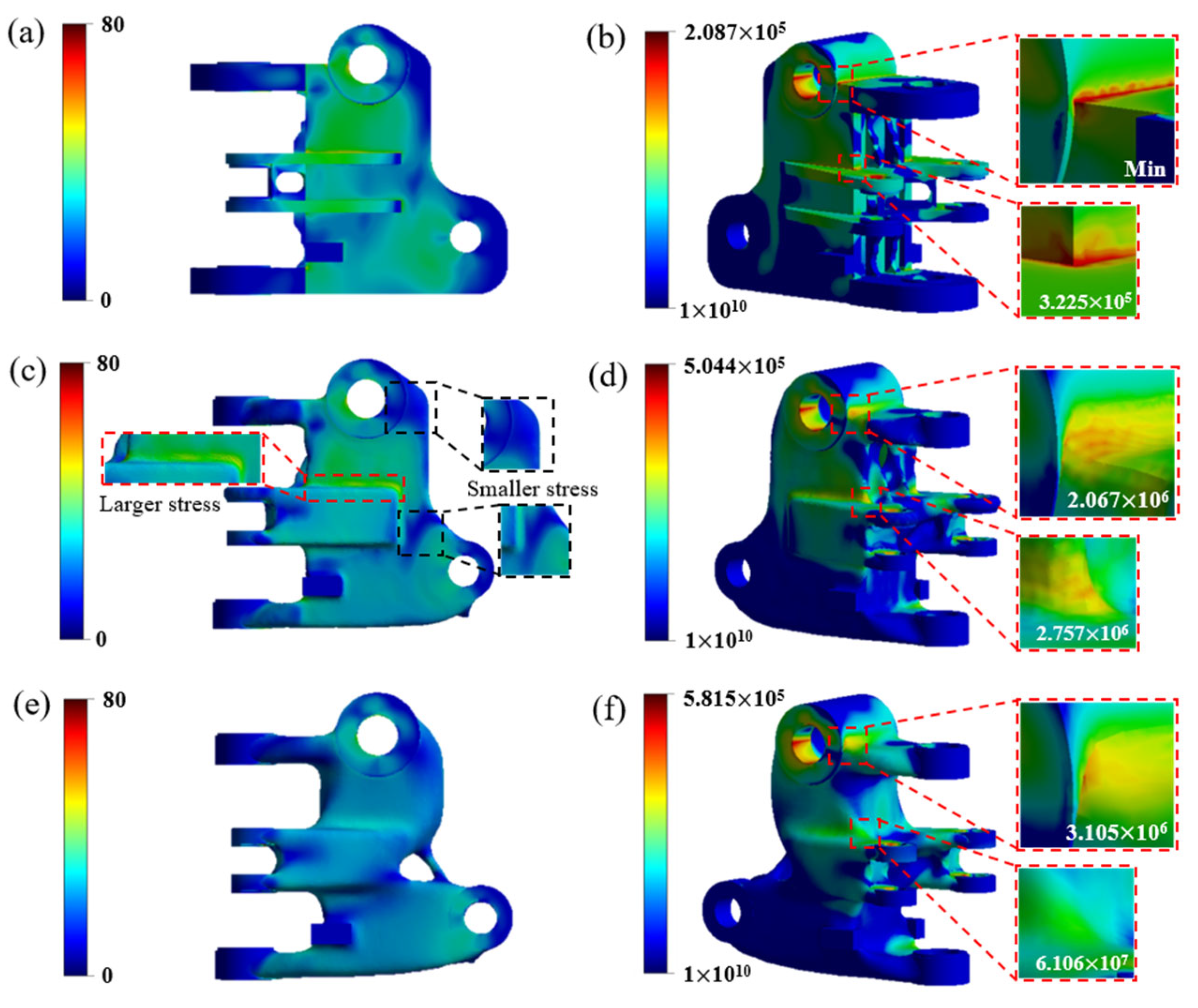
The inter-plate filled geometric reconstruction model was assigned the same boundary conditions as the original model, as shown in Figure 3b. To obtain accurate calculation results, the optimized model used three-dimensional solid elements and was finely meshed. A static structural analysis was then performed, and the results are shown in Figure 11c. The maximum stress was 96.34 MPa. The fatigue life of the optimized model was further predicted based on the S-N curve method, and the same modified S-N curve derived from the rotary joint material was used, applying a fully reversed constant-amplitude load with a scale factor of 1. The Goodman mean stress theory was adopted to analyze the fatigue life of the optimized rotary joint, and the results are shown in Figure 11d.
Figure 11.
Analysis results of the models: (a) equivalent stress distribution cloud diagram of the original model; (b) fatigue life distribution cloud diagram of the original model; (c) equivalent stress distribution cloud diagram of the inter-plate filled TO; (d) fatigue life distribution cloud diagram of the inter-plate filled TO; (e) equivalent stress distribution cloud diagram of the fully filled TO; (f) fatigue life distribution cloud diagram of the fully filled TO.
The fully filled geometric reconstruction model was assigned the same boundary conditions as the original model, as shown in Figure 3b. The model was finely meshed and subjected to static structural analysis, obtaining the stress distribution shown in Figure 11e, with a maximum stress of 93.03 MPa. Then, using the same modified S-N curve derived from the rotary joint material, a fully reversed constant-amplitude load with a scale factor of 1 was applied to the optimized model. The Goodman mean stress theory was adopted to analyze the fatigue life of the optimized rotary joint, and the results are shown in Figure 11f.
By comparing the minimum fatigue life of the rotary joint before optimization as shown in Figure 11b, 2.087 × 10⁵ cycles, the minimum fatigue life of the TO rotary joint based on the fully filled model as shown in Figure 11f increased to 5.815 × 10⁵ cycles. The fatigue life at the junction between the upper hinge platform surface and the main body of the rotary joint increased from 2.087 × 10⁵ cycles to 31.05 × 10⁵ cycles, while that at the junction between the rotary cylinder hinge platform surface and the main body of the rotary joint increased from 3.225 × 10⁵ cycles to 610.6 × 10⁵ cycles. The overall fatigue life was significantly improved. Compared with the TO results based on the inter-plate filled model as shown in Figure 11d, where the fatigue lives at the same locations were 20.67 × 10⁵ cycles and 27.57 × 10⁵ cycles, and the minimum life was 5.044 × 10⁵ cycles, the fatigue performance of this model was further improved. Furthermore, by comparing Figure 11e with Figure 11a and Figure 11c, it can be seen that the stress distribution of this model is more uniform than that of the original model and the TO result based on the inter-plate filled model, eliminating large areas of excessively high or low stress, indicating a more efficient utilization of the material. In terms of lightweight design, the optimized model obtained through this approach has a mass of 344.00 kg, which is lighter than the original model 391.34 kg and the TO model based on the inter-plate filled 368.94 kg. It not only improves the fatigue life but also achieves the goal of lightweight design.
In terms of manufacturability, the complex geometric shapes resulting from TO are suitable for the casting process, and the minimum member size constraint of 40 mm satisfies the 11 mm minimum wall thickness requirement for cast steel parts, which ensures good mold filling capability. Furthermore, the non-design space retains the original geometry, ensuring the compatibility of the workpiece with machine tool fixtures, facilitating subsequent precision machining.
In summary, the TO model based on the full filled design space not only ensures a significant improvement in fatigue life but also makes the stress distribution more uniform and the structure lighter. Therefore, for large assemblies involving complex non-linear contact, the sub-modeling technique can be effectively utilized to achieve this goal when performing TO on a specific component. For heavy-duty cantilever rotary structures characterized by roots subjected to massive overturning moments, limited installation space, and high susceptibility to fatigue failure, prioritizing the filling of internal cavities to reset the design domain can yield superior TO structures, thus better accomplishing the design objectives of enhancing fatigue life and achieving lightweight performance for the component.
The current research mainly focuses on the conceptual design and numerical verification stages, and the obtained conclusions rely mainly on high-precision numerical simulation. Therefore, in the future, scaled prototypes and full-scale prototypes will be manufactured for experimental validation to correlate the predicted fatigue life values with experimental data.
5. Conclusions
The rotary joint of the electrolytic aluminum anode dismantling robot was taken as the research object. A multi working condition analysis of the robot was conducted to identify the extreme working condition during normal operation. The resultant stress forces at the hinge joints of the rotary joint under this extreme condition were extracted to establish an equivalent model of the independent rotary joint. Subsequently, based on both the original model and the filled design space model with a reset design domain, TO and geometric reconstruction aimed at improving fatigue life were performed, followed by analysis and verification of the optimized structures. Addressing the problem that TO based on the original model could not yield a usable structure, the TO result after resetting the design domain not only yielded a usable structure, but also more than a two-fold improvement in fatigue life and about a 12.1% reduction in mass. The stress distribution became more uniform, with lower stress levels, longer fatigue life, and lighter weight, thus obtaining a superior optimization result. The present study and its results provide an effective new approach for various mechanical structures where TO design cannot be performed on the original structure.
Author Contributions
Conceptualization, C.Y., H.L. and D.Y.; methodology, C.Y., W.D. and Z.-Y.L.; formal analysis, C.Y., X.C. and Z.N.; investigation, C.Y., X.Z. and J.Z.; data curation, C.Y., Z.N. and J.Z.; writing—original draft preparation, C.Y., W.D. and Z.-Y.L.; writing—review and editing, H.L., D.Y. and X.C.; visualization, C.Y. and Z.-Y.L.; supervision, H.L. and D.Y.; project administration, H.L. and D.Y.; funding acquisition, H.L. All authors have read and agreed to the published version of the manuscript.
Funding
This research received no external funding.
Data Availability Statement
The original contributions presented in this study are included in the article. Further inquiries can be directed to the corresponding author.
Conflicts of Interest
Wendi Dong was employed by Shandong Laboratory of Aluminum Advanced Manufacturing in Binzhou (SLAAMB). Xingtao Zhang and Xizhong Cui were employed by Zouping Hongzheng New Material Technology Co., Ltd. The remaining authors declare that the research was conducted in the absence of any commercial or financial relationships that could be construed as a potential conflicts of interest.
References
- Tochilin, A.V.; Voronkov, I.E.; Alabin, A.V. Experience and prospects of using robotics in the nuclear power industry. IOP Conf. Ser. Mater. Sci. Eng. 2021, 1047, 012193. [Google Scholar] [CrossRef] [Scilit]
- Delmerico, J.; Mintchev, S.; Giusti, A.; Gromov, B.; Melo, K.; Horvat, T.; Cadena, C.; Hutter, M.; Ijspeert, A.; Floreano, D.; et al. The current state and future outlook of rescue robotics. J. Field Robot. 2019, 36, 1171–1191. [Google Scholar] [CrossRef] [Scilit]
- Bogue, R. Robots in the nuclear industry: A review of technologies and applications. Ind. Robot. 2011, 38, 113–118. [Google Scholar] [CrossRef] [Scilit]
- Guan, D.; Yang, N.; Lai, J.; Siu, M.-F.F.; Jing, X.; Lau, C.-K. Kinematic modeling and constraint analysis for robotic excavator operations in piling construction. Autom. Constr. 2021, 126, 103666. [Google Scholar] [CrossRef] [Scilit]
- Zhang, L.; Zhao, J.; Long, P.; Wang, L.; Qian, L.; Lu, F.; Song, X.; Manocha, D. An autonomous excavator system for material loading tasks. Sci. Robot. 2021, 6, eabc3164. [Google Scholar] [CrossRef] [Scilit]
- Ma, X.; Mao, C.; Liu, G. Can robots replace human beings?—Assessment on the developmental potential of construction robot. J. Build. Eng. 2022, 56, 104727. [Google Scholar] [CrossRef] [Scilit]
- Wu, C.; Xu, Y.; Fang, J.; Sun, G.; Steven, G.P.; Li, Q. Topology optimization for multi-component robotic arms under time-varying loads. Struct. Multidiscip. Optim. 2025, 68, 188. [Google Scholar] [CrossRef] [Scilit]
- Arhore, E.G.; Yasaee, M.; Dayyani, I. Comparison of GA and topology optimization of adherend for adhesively bonded metal composite joints. Int. J. Solids Struct. 2021, 226–227, 111078. [Google Scholar] [CrossRef] [Scilit]
- Lee, Y.-S.; González, J.A.; Lee, J.H.; Kim, Y.I.; Park, K.C.; Han, S. Structural topology optimization of the transition piece for an offshore wind turbine with jacket foundation. Renew. Energy 2016, 85, 1214–1225. [Google Scholar] [CrossRef] [Scilit]
- Zargham, S.; Ward, T.A.; Ramli, R.; Badruddin, I.A. Topology optimization: A review for structural designs under vibration problems. Struct. Multidiscip. Optim. 2016, 53, 1157–1177. [Google Scholar] [CrossRef] [Scilit]
- Wang, M.Y.; Wang, X.; Guo, D. A level set method for structural topology optimization. Comput. Methods Appl. Mech. Eng. 2003, 192, 227–246. [Google Scholar] [CrossRef] [Scilit]
- Huang, X.; Xie, Y.M. Convergent and mesh-independent solutions for the bi-directional evolutionary structural optimization method. Finite Elem. Anal. Des. 2007, 43, 1039–1049. [Google Scholar] [CrossRef] [Scilit]
- Liu, L.; Yan, J.; Cheng, G. Optimum structure with homogeneous optimum truss-like material. Comput. Struct. 2008, 86, 1417–1425. [Google Scholar] [CrossRef] [Scilit]
- Guo, X.; Zhang, W.; Zhang, J.; Yuan, J. Explicit structural topology optimization based on moving morphable components (MMC) with curved skeletons. Comput. Methods Appl. Mech. Eng. 2016, 310, 711–748. [Google Scholar] [CrossRef] [Scilit]
- Holmberg, E.; Torstenfelt, B.; Klarbring, A. Stress constrained topology optimization. Struct. Multidiscip. Optim. 2013, 48, 33–47. [Google Scholar] [CrossRef] [Scilit]
- Senhora, F.V.; Menezes, I.F.M.; Paulino, G.H. Topology optimization with local stress constraints and continuously varying load direction and magnitude: Towards practical applications. Proc. R. Soc. A 2023, 479, 20220436. [Google Scholar] [CrossRef] [Scilit]
- Navarrina, F.; Muiños, I.; Colominas, I.; Casteleiro, M. Topology optimization of structures: A minimum weight approach with stress constraints. Adv. Eng. Softw. 2005, 36, 599–606. [Google Scholar] [CrossRef] [Scilit]
- da Silva, G.A.; Beck, A.T. Reliability-based topology optimization of continuum structures subject to local stress constraints. Struct. Multidiscip. Optim. 2017, 57, 2339–2355. [Google Scholar] [CrossRef] [Scilit]
- Huang, X.; Li, S.; Miao, C.; Hou, L.; Chen, Y. Generative adversarial network for stress-minimizing topology optimization. Int. J. Mech. Mater. Des. 2025, 21, 2013–2030. [Google Scholar] [CrossRef] [Scilit]
- Yang, D.; Liu, H.; Zhang, W.; Li, S. Stress-constrained topology optimization based on maximum stress measures. Comput. Struct. 2018, 198, 23–39. [Google Scholar] [CrossRef] [Scilit]
- Hagenah, H.; Böhm, W.; Breitsprecher, T.; Merklein, M.; Wartzack, S. Modelling, Construction and Manufacture of a Lightweight Robot Arm. Procedia CIRP 2013, 12, 211–216. [Google Scholar] [CrossRef] [Scilit]
- Kouritem, S.A.; Abouheaf, M.I.; Nahas, N.; Hassan, M. A multi-objective optimization design of industrial robot arms. Alex. Eng. J. 2022, 61, 12847–12867. [Google Scholar] [CrossRef] [Scilit]
- Briot, S.; Goldsztejn, A. Topology optimization of industrial robots: Application to a five-bar mechanism. Mech. Mach. Theory 2018, 120, 30–56. [Google Scholar] [CrossRef] [Scilit]
- Lakshmi Srinivas, G.; Javed, A. Topology optimization of rigid-links for industrial manipulator considering dynamic loading conditions. Mech. Mach. Theory 2020, 153, 103979. [Google Scholar] [CrossRef] [Scilit]
- Bien, D.X. Investigation of Driving Torques at the Joints of Industrial Robot Arms Based on the Topology Optimization Technique. J. Appl. Comput. Mech. 2023, 9, 820–833. [Google Scholar]
- da Silva, G.A.; Beck, A.T.; Sigmund, O. Topology optimization of compliant mechanisms considering stress constraints, manufacturing uncertainty and geometric nonlinearity. Comput. Methods Appl. Mech. Eng. 2020, 365, 112972. [Google Scholar] [CrossRef] [Scilit]
- Sung, M.K.; Lee, S.; Burns, D.E. Robust topology optimization of a flexural structure considering multi-stress performance for force sensing and structural safety. Struct. Multidiscip. Optim. 2021, 65, 030887. [Google Scholar] [CrossRef] [Scilit]
- Villalba, D.; Gonçalves, M.; Dias-de-Oliveira, J.; Andrade-Campos, A.; Valente, R. IGA-based topology optimization in the design of stress-constrained compliant mechanisms. Struct. Multidiscip. Optim. 2023, 66, 244. [Google Scholar] [CrossRef] [Scilit]
- Mu, Z.; Liu, L.; Jia, L.; Zhang, L.; Ding, N.; Wang, C. Intelligent demolition robot: Structural statics, collision detection, and dynamic control. Autom. Constr. 2022, 142, 104490. [Google Scholar] [CrossRef] [Scilit]
- Ding, F. Finite element analysis and optimal design of robotic arm. Appl. Comput. Eng. 2023, 33, 88–93. [Google Scholar] [CrossRef] [Scilit]
- Li, H.; Li, Y. Finite element analysis and structural optimization design of multifunctional robotic arm for garbage truck. Front. Mech. Eng. 2025, 11, 1543967. [Google Scholar] [CrossRef] [Scilit]
- Wang, B.; Bai, J.; Zuo, W. Contact and Geometric Nonlinearities Topology Optimization Constrained with Stress. Int. J. Numer. Methods Eng. 2025, 126, e70077. [Google Scholar] [CrossRef] [Scilit]
- Zhang, L.; Jiang, B.; Zhang, P.; Yan, H.; Xu, X.; Liu, R.; Tang, J.; Ren, C. Methods for fatigue-life estimation: A review of the current status and future trends. Nanotechnol. Precis. Eng. 2023, 6, 025001. [Google Scholar] [CrossRef] [Scilit]
- Leipholz, H.H.E. On the modified S-N curve for metal fatigue prediction and its experimental verification. Eng. Fract. Mech. 1986, 23, 495–505. [Google Scholar] [CrossRef] [Scilit]
- Strzelecki, P.; Tomaszewski, T. Analytical models of the S-N curve based on the hardness of the material. Procedia Struct. Integr. 2017, 5, 832–839. [Google Scholar] [CrossRef] [Scilit]
- Marciniak, Z.; Branco, R.; Martins, R.F.; Rozumek, D.; Macek, W. Effect of elliptical defect orientation on the durability of specimens subjected to cyclic bending. Procedia Struct. Integr. 2022, 37, 606–613. [Google Scholar] [CrossRef] [Scilit]
- Ronchei, C. Fatigue Strength Estimation of Ductile Cast Irons Containing Solidification Defects. Metals 2023, 13, 83. [Google Scholar] [CrossRef] [Scilit]
- Teng, X.; Pang, J.; Liu, F.; Zou, C.; Bai, X.; Li, S.; Zhang, Z. Fatigue Life Prediction of Gray Cast Iron for Cylinder Head Based on Microstructure and Machine Learning. Acta Metall. Sin. 2023, 36, 1536–1548. [Google Scholar] [CrossRef] [Scilit]
- Sladký, M.; Machac, M.; Papuga, J.; Jebácek, I. The fatigue life prediction of thin-walled welded joints. In Proceedings of the 34th Congress of the International Council of the Aeronautical Sciences (ICAS), Florence, Italy, 9–13 September 2024. [Google Scholar]
- Chiocca, A.; Frendo, F.; Aiello, F.; Bertini, L. Influence of residual stresses on the fatigue life of welded joints. Numerical simulation and experimental tests. Int. J. Fatigue 2022, 162, 106901. [Google Scholar] [CrossRef] [Scilit]
- Wang, L.; Qian, X.; Feng, L. Effect of welding residual stresses on the fatigue life assessment of welded connections. Int. J. Fatigue 2024, 189, 108570. [Google Scholar] [CrossRef] [Scilit]
- Meng, Z.; Wang, D.; Han, X.; Zhang, Z.; Zhang, X.; Ni, Y.; Dong, J.; Xu, W.; Liang, H. Fatigue-constrained lightweight design of electric truck frame considering power battery system layout. Struct. Multidiscip. Optim. 2025, 68, 133. [Google Scholar] [CrossRef] [Scilit]
- Yago, D.; Cante, J.; Lloberas-Valls, O.; Oliver, J. Topology Optimization Methods for 3D Structural Problems: A Comparative Study. Arch. Comput. Methods Eng. 2022, 29, 1525–1567. [Google Scholar] [CrossRef] [Scilit]
- Zhao, T.; Zhang, Y.; Ou, Y.; Ding, W.; Cheng, F. Fail-safe topology optimization considering fatigue. Struct. Multidiscip. Optim. 2023, 66, 132. [Google Scholar] [CrossRef] [Scilit]
- Huang, Y.; Chen, X.; Yao, S. Strength-constrained topology optimization considering static stress and fatigue using isogeometric analysis. Struct. Multidiscip. Optim. 2025, 68, 182. [Google Scholar] [CrossRef] [Scilit]
- Amstutz, S.; Novotny, A.A. Topological optimization of structures subject to Von Mises stress constraints. Struct. Multidiscip. Optim. 2009, 41, 407–420. [Google Scholar] [CrossRef] [Scilit]
- Li, P.; Xi, G.; Xiao, L.; Gao, R.; Wang, J.; Song, X. Topology optimization and model fusion reconstruction of pump truck boom structure under multi working conditions. Proc. Inst. Mech. Eng. C 2024, 239, 2700–2714. [Google Scholar] [CrossRef] [Scilit]

Disclaimer/Publisher’s Note: The statements, opinions and data contained in all publications are solely those of the individual author(s) and contributor(s) and not of MDPI and/or the editor(s). MDPI and/or the editor(s) disclaim responsibility for any injury to people or property resulting from any ideas, methods, instructions or products referred to in the content. |
© 2026 by the authors. Licensee MDPI, Basel, Switzerland. This article is an open access article distributed under the terms and conditions of the Creative Commons Attribution (CC BY) license.