


Abstract
The tool-point frequency response function (FRF) of a spindle–tool system plays a crucial role in predicting machining stability. Among the factors influencing the FRF, the interface characteristics between the spindle and the tool holder are particularly significant, especially when different holder designs are used. This study focused on identifying these interface characteristics for two common tool holder types—BT and BBT—to improve FRF prediction accuracy. The receptance coupling substructure analysis (RCSA) method was employed in conjunction with finite element modeling (FEM) to characterize the spindle–tool holder interfaces without needing extensive experimental tapping tests. Finite element models were developed to generate receptance components for various tool holder–tool assemblies, enabling efficient and accurate coupling within the RCSA framework. The identified interface parameters were applied to predict the tool-point FRFs of the cutter clamped in a BT tool holder with different overhang lengths. The predicted and measured tool compliances differed by 3–6.4%, demonstrating high agreement and reliability. The proposed methodology provides a powerful tool for predictive modeling of dynamic behavior in spindle–tool systems under varying tooling conditions, enhancing process planning and evaluation of the cutting stability in high-precision machining.
1. Introduction
Machining chatter is a self-excited vibration phenomenon caused by the interaction between the cutting process dynamics and the structural dynamics of the machine tool system [1,2]. The dynamic response of the spindle–tool system under cutting forces reflects the combined influence of the machine structure, spindle, tool holder, and cutting tool. As one of the most critical subsystems in machining, the spindle–tool holder–tool assembly plays a decisive role in machining performance, surface quality, and process stability. Choi and Lee [3] demonstrated that more than 50% of the total structural deformation at the cutting point originates from this assembly during machining operations.
When different tool holders are mounted on the same spindle, the contact stiffness at the spindle–tool holder interface significantly varies due to differences in clamping force, taper geometry, assembly tolerances, and surface finish. These variations lead to different deflection behaviors under cutting forces, thereby directly affecting machining accuracy and stability [4]. Previous studies have shown that the mechanical characteristics of the tool holder–spindle interface are influenced by multiple factors, including drawbar force, taper contact conditions, and manufacturing precision [5,6,7,8,9].
Enhancing the dynamic characteristics of machine tools and improving cutting stability are, therefore, essential for increasing machining performance. For a given machine tool, optimal cutting parameters are commonly determined using stability lobe diagrams derived from the tool-point frequency response function (FRF) of the spindle–tool system. Traditionally, the tool-point FRF is obtained using experimental impact (tapping) tests. However, when multiple cutting tools or tool holder configurations are involved, repeated experimental measurements become time-consuming, costly, and inefficient. To address this limitation, numerous studies have proposed the use of receptance coupling substructure analysis (RCSA) to rapidly predict the FRFs of different spindle–tool assemblies [10,11,12,13,14,15,16].
Schmitz et al. [10,11] first introduced the receptance coupling technique, which synthesizes the dynamic behavior of an assembled system by coupling the experimentally obtained FRFs of individual substructures, such as the spindle, tool holder, and cutting tool. This approach eliminates the need for repeated vibration experiments for each tool assembly and significantly improves the efficiency of machining stability prediction. Subsequent research extended this technique to analyze the influence of the tool overhang length and tool geometry on the dynamic response and cutting stability of spindle–tool systems [12,13,14].
In early implementations of RCSA, only translational (linear displacement) receptance components were considered, while rotational displacement components were neglected. This simplification resulted in reduced prediction accuracy, particularly for systems subjected to bending moments at the interfaces. To overcome this limitation, later studies incorporated both lateral translational displacement and rotational displacement at the interfaces between substructures [15,16,17,18,19,20]. Park et al. [15] introduced lateral and rotational receptances at the spindle–tool holder interface under applied lateral forces and bending moments, using beam theory to analytically derive rotational FRFs. Albertelli et al. [16] employed finite-difference methods to compute both translational and rotational FRFs of spindle–tool holder substructures. Ahmadi and Ahmadian [18] modeled the spindle–tool holder interface as an elastic layer to investigate the effect of contact pressure on dynamic behavior. Erturk et al. [19] and Özşahin et al. [20] applied RCSA to simplified spindle–tool holder–tool models and proposed parameter identification methods for interface dynamics, which were validated using experimental analysis. Schmitz et al. [21] developed a third-generation RCSA framework for shrink-fit tool holders, in which position-dependent translational and rotational stiffness and damping parameters were obtained from finite element simulations and distributed along the tool holder contact length. Their approach significantly improved tool-point FRF prediction accuracy and reduced reliance on empirical fitting parameters by introducing multiple coupling locations and FEM-derived interface properties.
Budak et al. [22,23] simplified the spindle, tool holder, and cutting tool geometries by modeling them as Timoshenko beams with varying cross-sections to further reduce the experimental effort required to obtain substructure FRFs. They used analytical formulations to derive the required receptance components while accounting for interface contact characteristics. In these studies, interface properties were represented by normal and rotational stiffness and damping coefficients, which were assembled into interface stiffness matrices. This modeling framework enabled investigating the influence of drawbar clamping force on interface stiffness and damping characteristics [24].
Introducing interface stiffness matrices also allows interface properties to be identified using inverse receptance coupling calculations based on experimental data. Once identified, these parameters can be reused to predict the dynamic responses of different tool holder modules mounted on the same spindle [25]. Yin et al. [26] proposed an improved joint parameter identification approach based on substructure synthesis methods to predict assembled structural responses from substructure FRFs.
Recent studies have further advanced inverse receptance coupling techniques to reduce experimental effort while improving interface parameter identification accuracy. For example, Sulitka et al. [27] proposed a single-artifact inverse RCSA approach that explicitly accounts for cross-receptance terms between translational and rotational degrees of freedom. By introducing an improved cross-receptance formulation, their method enhances the numerical stability and accuracy of assembled tool-point FRF predictions while requiring only a limited number of experimental measurements. This work highlights the importance of accurately modeling coupling effects in inverse RCSA frameworks, particularly for bending-dominated dynamic responses.
Despite these advancements, experimental identification of rotational receptances remains challenging and time-consuming. Standard impact testing procedures typically provide only translational displacement responses to normal forces, while rotational responses to forces or translational responses to bending moments must be estimated using approximation techniques, often requiring multiple trials and careful selection of measurement points [28,29,30,31]. To address these challenges, Montevecchi et al. [29] and Ji et al. [31] proposed advanced RCSA methods that enable the computation of rotational receptances from a reduced number of impact tests. Hung et al. [32] demonstrated that finite element analysis (FEA) can be effectively used to improve bending moment response prediction, thereby enhancing receptance coupling accuracy. More recently, inverse receptance coupling techniques and novel contact parameter identification methods have been developed to improve FRF prediction accuracy for tool holders combined with tools of different lengths and clamping conditions [32,33]. More recently, Zhao et al. [34] proposed a method to identify contact parameters at the tool holder–tool interface for predicting the frequency response functions (FRFs) of assembled tool systems. Their results show reduced tool-point FRF prediction errors, particularly when variations in tool clamping length are considered. Chaux et al. [35] developed a numerical framework for free–free tool FRF prediction by combining finite-difference methods, reciprocity principles, and data-driven techniques, thereby reducing experimental effort and improving receptance estimation accuracy. While effective for tools with complex geometries, their approach focuses on free–free tool dynamics and does not address assembled spindle–tool systems.
Previous studies have confirmed that receptance coupling substructure analysis (RCSA) is an effective and efficient approach for predicting tool-point frequency response functions. Nevertheless, most existing research has primarily addressed the coupling behavior of tool holder–tool assemblies, whereas the dynamic characteristics of the spindle nose–tool holder interface have received comparatively limited attention. This gap is particularly important for milling machines, where tool holders with different specifications are frequently required to accommodate diverse machining tasks, leading to interface dynamics that vary significantly with holder design.
In this work, the influence of different tool holder specifications, specifically BT and BBT modules, on the tool-point FRF of a milling spindle is systematically investigated. An interface-centered inverse RCSA framework is proposed, in which the coupling interface is explicitly defined at the physical spindle holder clamping location. Unlike conventional RCSA-based approaches that are often configuration-specific or rely on identical holder shank geometries, the proposed method enables direct identification and reuse of spindle holder interface dynamics across tool holders with different shank geometries and dimensions. By integrating experimental measurements with validated three-dimensional finite element models, the approach allows realistic representation of complex geometries and mass–stiffness distributions while avoiding algebraic reconstruction of receptances. As a result, accurate tool-point FRF prediction is achieved with reduced experimental effort, which enhances the generality and practical applicability of RCSA for industrial spindle–tool systems.
2. Basic Theory of Receptance Coupling Method
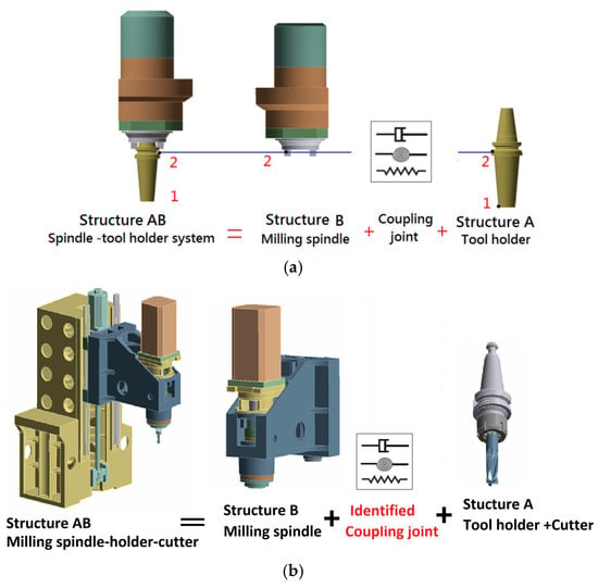
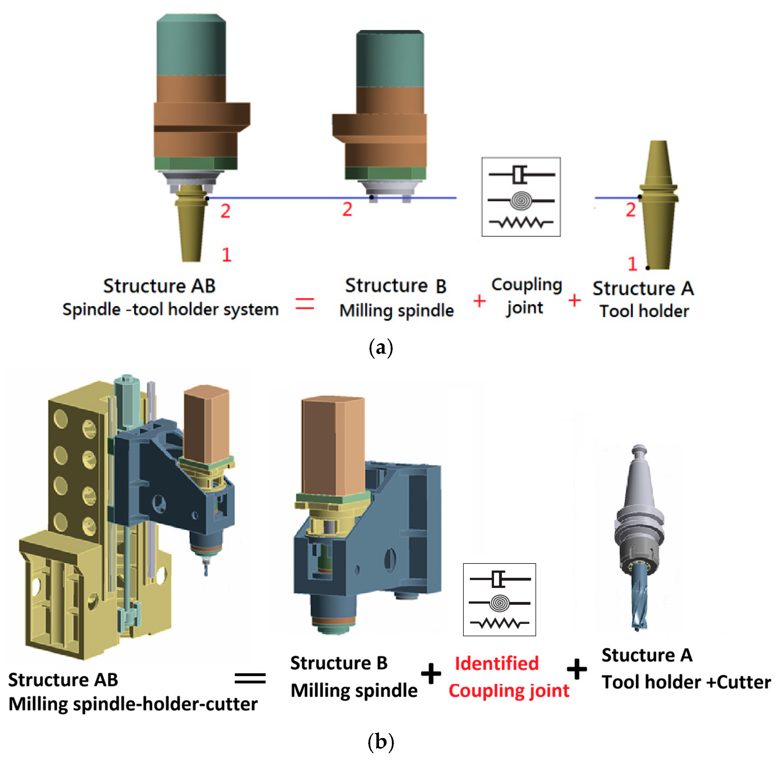
In this study, the dynamic properties of the assembled structure were obtained by coupling the receptances of individual substructures. The assembled structure (AB) consisted of a milling spindle (substructure B) and a tool holder (substructure A), connected through the bonding interface between the spindle nose and the tool holder taper, as illustrated in Figure 1a. Milling spindle tooling systems with different tool holders, featuring varying shank geometries and dimensions, were investigated.
Figure 1.
(a) Schematic of the coupling of substructures, including spindle unit and tool holder; (b) coupling operation of milling spindle with tool holder–cutter module.
Given the dominant influence of the spindle holder interface on the dynamic behavior of the spindle–tool system, the coupling joint was assumed at the contact interface between the spindle nose inner taper and the tool holder outer taper. The coupling operation was performed between the milling spindle and the complete tool holder module. Unlike Schmit’s approach [25,36,37], substructure B in the present study was defined as the milling spindle without the upper portion of the holder, allowing different tool holder–cutter assemblies to be accommodated, while substructure A comprised the entire tool holder, including the taper and shank.
The spindle holder interface was modeled as an elastic joint with dynamic characteristics. Once identified, these interface parameters were used to predict the tool-point frequency response functions (FRFs) of the milling cutter through receptance coupling between the spindle and the tool holder–cutter assembly, as shown in Figure 1b.
For substructure (A) or the tool holder, the displacements at endpoints 1 and 2 (X1 and XA2) can be related to the applied forces (F1 and FA2) in the following expression:
For the spindle (substructure ), the compliance at the spindle nose (point B2) is expressed as
The above equation shows the relationship between the displacement at the spindle nose (point B2) and force .
As illustrated in Figure 1, the coupling interface in the present study is explicitly defined at point 2, corresponding to the physical clamping location between the spindle nose and the tool holder. By formulating the inverse RCSA directly at this interface, the identified spindle-side receptance [HB22] represents an equivalent boundary compliance that is independent of the specific holder shank geometry, enabling application to tool holders with different shank dimensions and geometries.
When substructures A and B are coupled, displacement compatibility and force equilibrium at the interface require
F2 = FA2 + FB2, X2 = XA2 = XB2
Substituting Equations (1)–(3), the generalized displacement at tool point 1 due to an external force F1 can be obtained as follows:
where [HA22] + [HB22] represents the coupled receptance components of the tool holder–cutter module (substructure A) and milling spindle (substructure B). The frequency response function at the tool end due to the excitation F1 can then be obtained from Equation (4).
At each measurement location on the structure, the displacement response comprises both linear translational displacement () and rotational displacement (), corresponding to the applied force () and moment (), respectively. The generalized relationship between the displacement vector and the force vector is, therefore, expressed as follows:
where denotes the receptance component matrix or the frequency response matrix of substructure A. A general form of the receptance matrix of and can be expressed as
Considering the elastic interface between the tool holder (A) and the spindle nose (B), the interface force is related to the relative interface motion by the interface dynamic stiffness matrix [19]:
where , and are the interface dynamic contact stiffness under transverse force f and bending moment M, and , and are the damping coefficients of the contact interface. Upon inclusion of contact characteristics in the receptance coupling formulation, the resulting coupling equation for predicting the compliance matrix of the assembled structure is given as
in which
3. Experimental Measurements of Frequency Response Functions
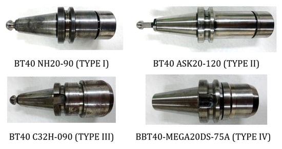
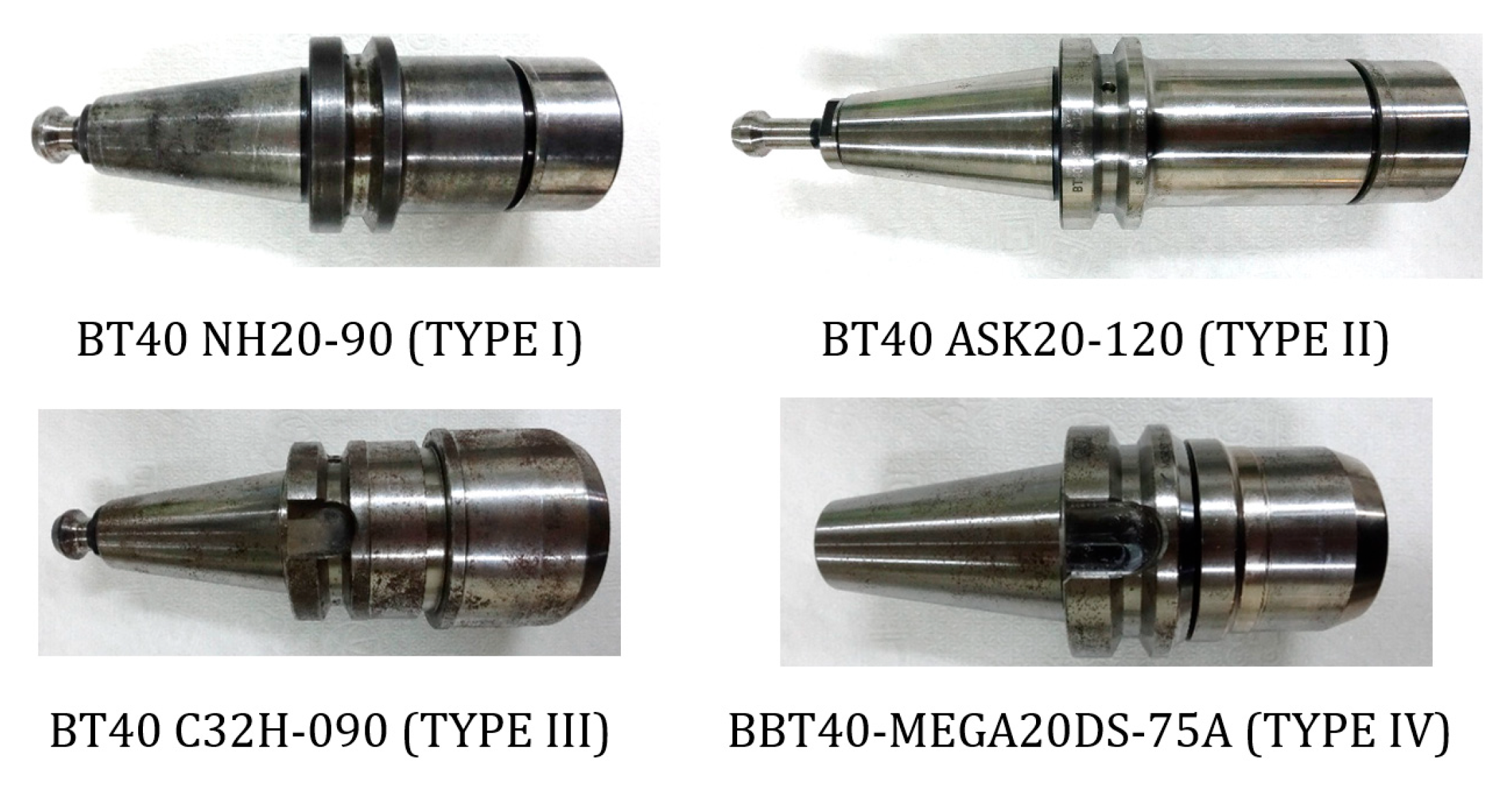
In this study, four different kinds of tool holders were adopted to investigate the interface characteristics, including one BBT holder (TYPE-IV BBT40-MEGA20DS-75A) and three BT40 holders with different shanks (TYPE-I BT40 NH20-90, TYPE-II BT40 ASK20-120, and TYPE-III BT40 C32H-090), as shown in Figure 2. The required compliance matrices of the substructures—namely, the tool holder and the spindle nose of the milling machine—must be evaluated to identify the interface characteristics. The frequency response functions (FRFs) corresponding to the translational displacement-to-force components needed for the coupling operation were obtained using impact (tapping) tests.
Figure 2.
Tool holder modules with different specifications.
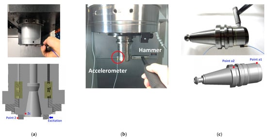
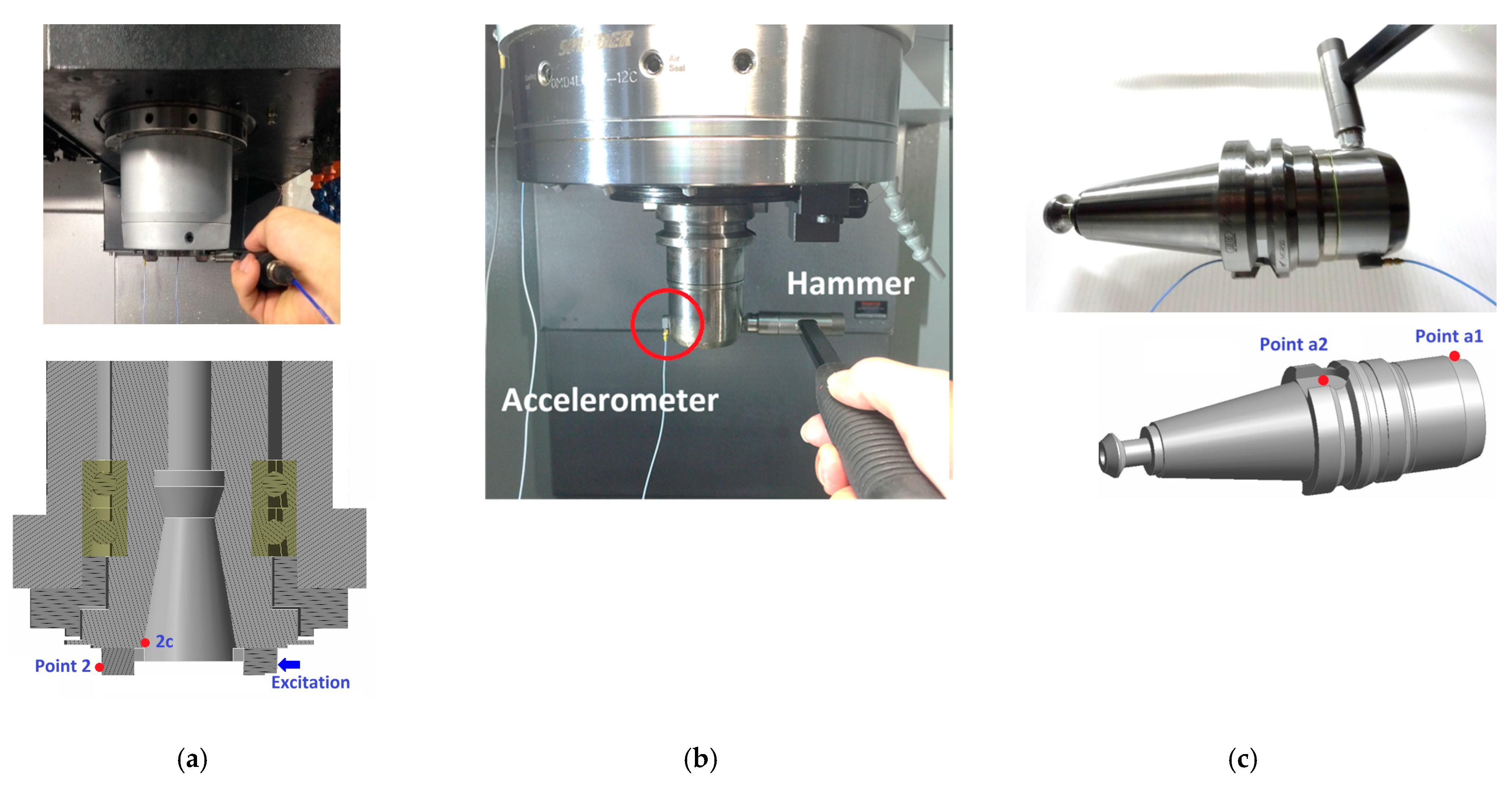
The instruments used for impact testing included the following: (1) an accelerometer (PCB Inc., Tonawanda, NY, USA, 352A25; mass: 0.6 g; sensitivity: (±15%) 2.5 mV/g; and natural frequency: 1 to 10k Hz); (2) an impact hammer (PCB Inc. 086C03; sensitivity: 2.25 mV/N; and measurement range: 222 N pk); (3) a data acquisition module (National Instruments Co., Austin, TX, USA; NI-9234; AC/DC coupling; 4-input channel; 24 bit; 51.2 kSPS; and BNC); and (4) an FFT spectrum analyzer (PROWAVE Engineering Inc., Kaohsiung City, Taiwan; PW 700 series). The experimental configurations are illustrated in Figure 3. In the test of the spindle–tool holder structure, it was suspended by very soft cords, as in a free state. The impact hammer was applied to the end of the tool holder (point a1) and the clamping point a2, as shown in Figure 3c. The response was measured with an accelerometer, which was attached to the backside of the excitation point. The vibration signal was assessed via the DAQ module and then processed with an FFT spectrum analyzer. Similarly, in assessment of receptance components of spindle nose [HB22], denoting the direct FRF at the point 2, was measured by tapping tests on spindle nose. The experimental configuration is illustrated in Figure 3a. The accelerometer was mounted at point 2, where the clamping point of the spindle nose with holder was. The other sensor was mounted on point 2c on the inside surface of the spindle nose. The responses at point 2 and 2c, Hb22 and Hb22c, were measured under excitation applied on the spindle nose. Other components such as the rotational displacement against moment loading, Lb22, Nb22, and Pb22 were estimated by using the finite-difference method.
Figure 3.
Vibration experiment for assessing the FRFs of the structural components (a) at the spindle nose (substructure B), (b) at the spindle–tool holder interface (structure AB), and (c) the tool holder module (substructure A).
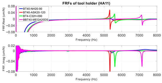
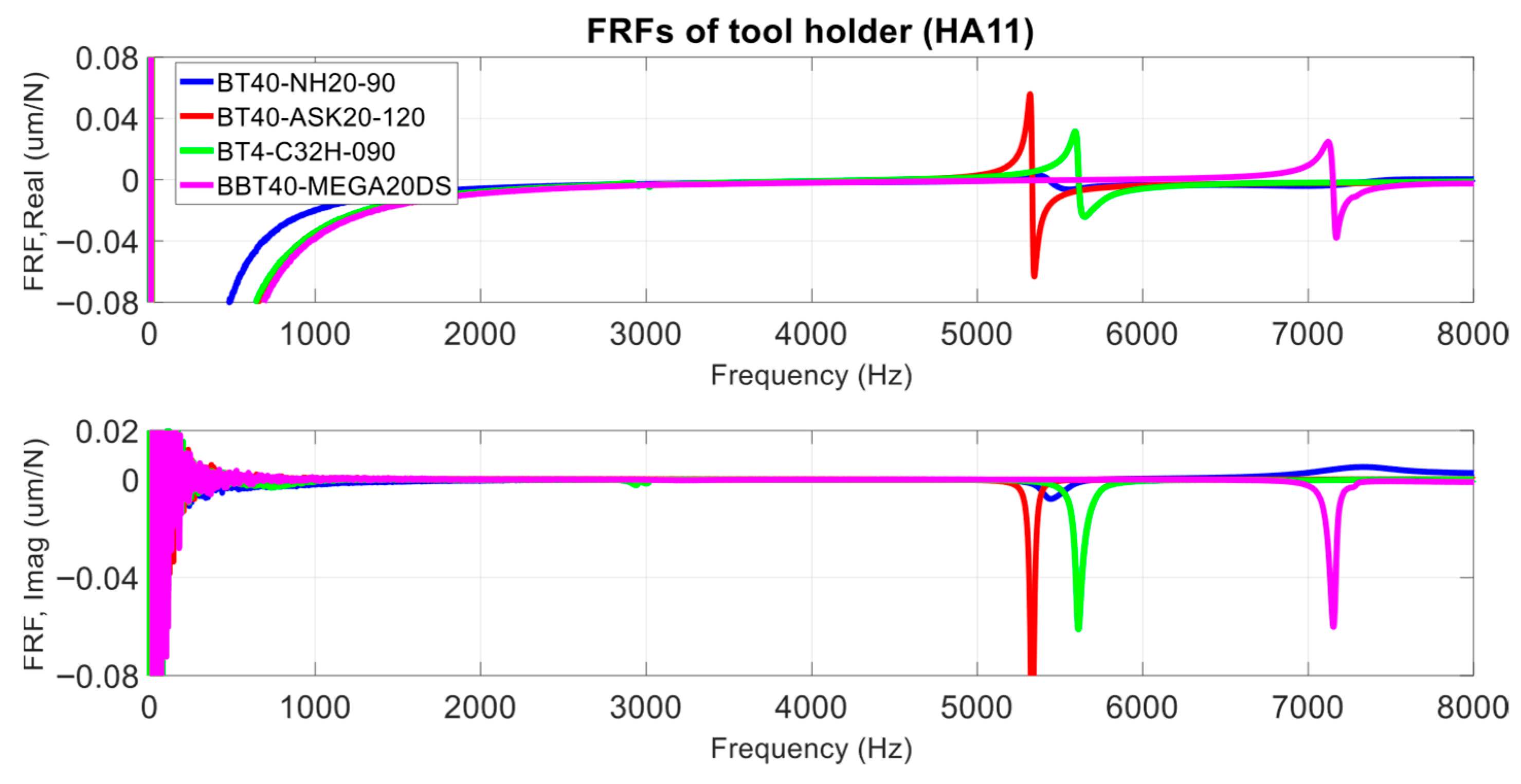
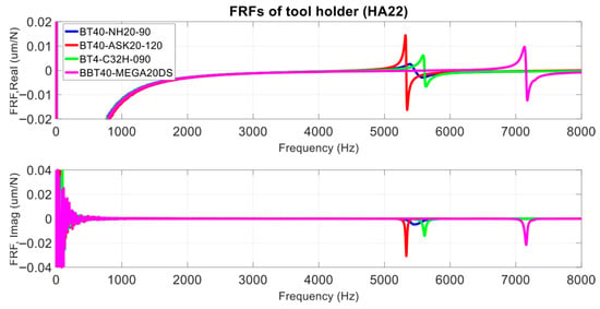
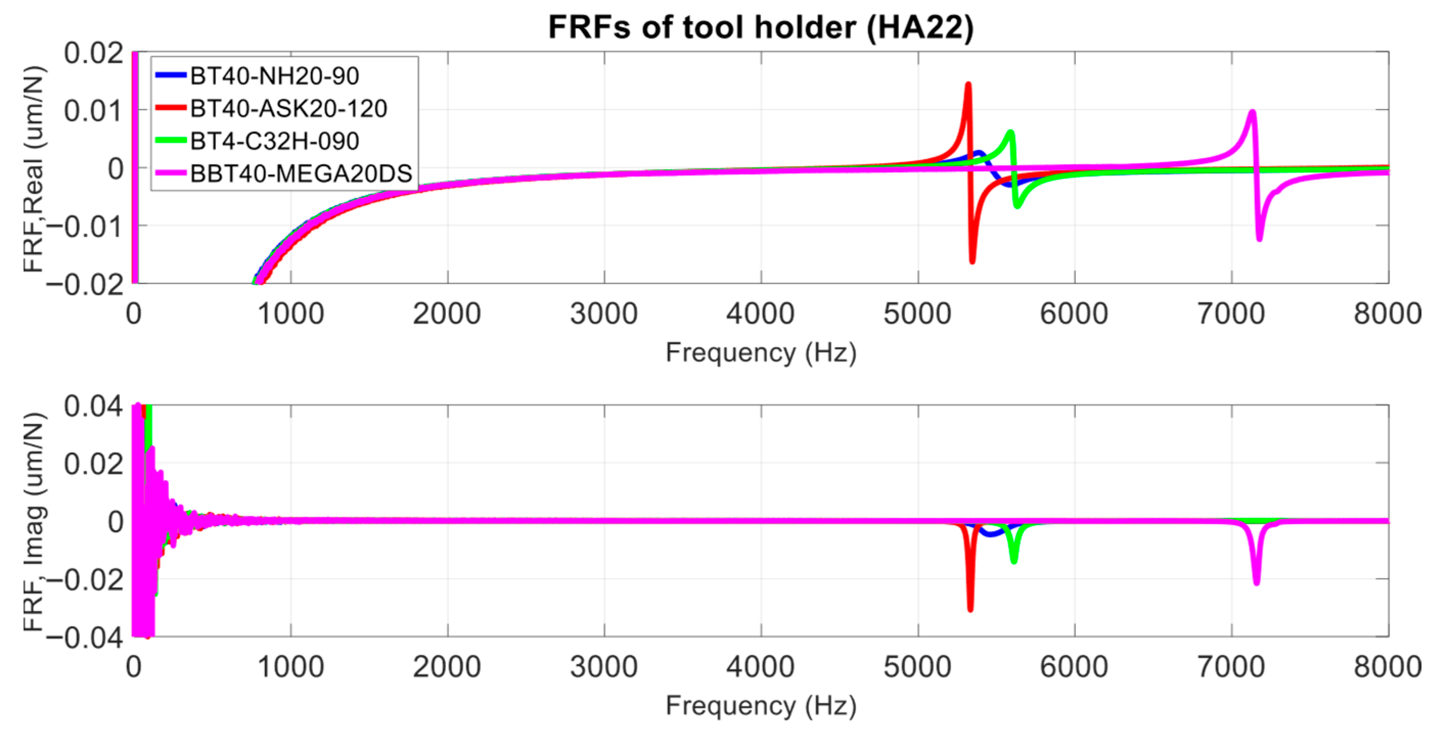
Figure 4 and Figure 5 depict the frequency response functions of the tool holders, which were measured at the end of the holder (point a1) and the clamping point (point a2), termed as Ha11 and Ha22, respectively. Figure 4 shows that the primary natural frequency of the tool holder ranged from 5000 to 7000 HZ, varying with the holder dimensions. The three BT holders and the BBT holder also showed different compliance at the critical modes. The BBT holder had a higher frequency and rigidity than the other BT holders.
Figure 4.
Comparisons of the FRFs measured at the collet nuts of the tool holders with different geometric designs.
Figure 5.
Comparisons of the FRFs measured at the retention knobs of the tool holders with different geometric designs.
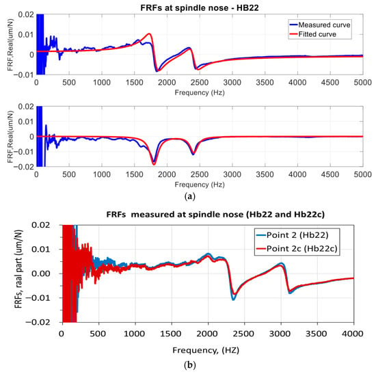
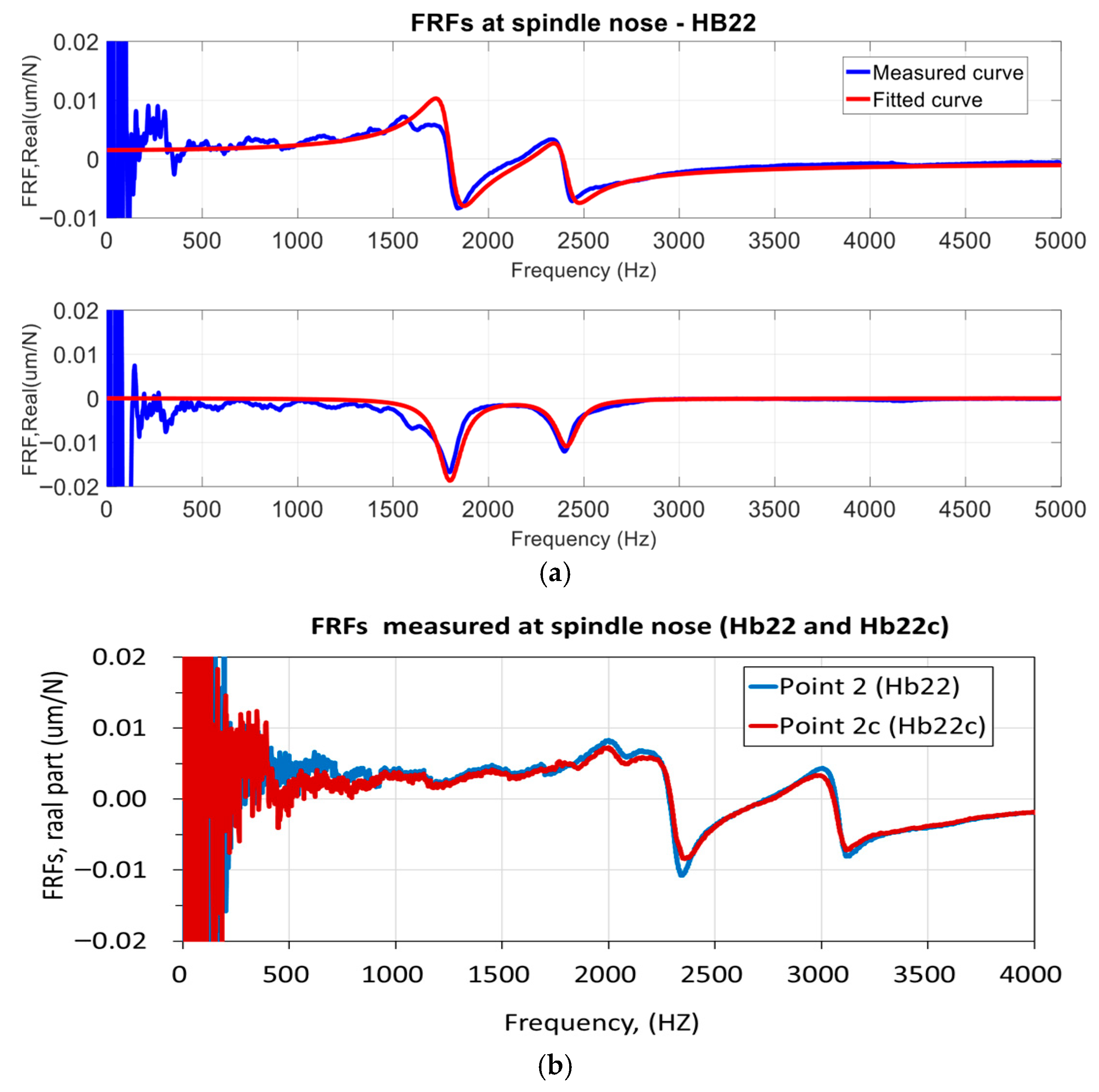
The direct FRFs measured at the point 2 and point 2c on the spindle nose, termed as HB22 and HB22c, respectively, are illustrated in Figure 6, which shows two fundamental modes at 1766 and 2366 Hz, with compliances of 0.024 and 0.01 . The rotational displacement against the applied force, Nb22, can be calculated as Nb22 = (Hb22 − Hb22c)/S, where S is the distance between point 2 and point 2c. Given Hb22 and Nb22, the components Lb22 and Pb22 can be obtained, that is Lb22 = Nb22 and Pb22 = (Lb22·Nb22)/Hb22.
Figure 6.
Frequency response functions measured at the spindle nose: (a) real part and imaginary part of FRF and (b) comparisons of FRFs, HB22, and HB22c.
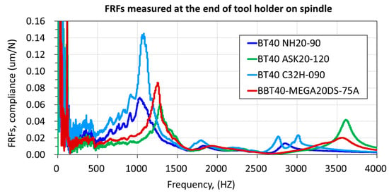
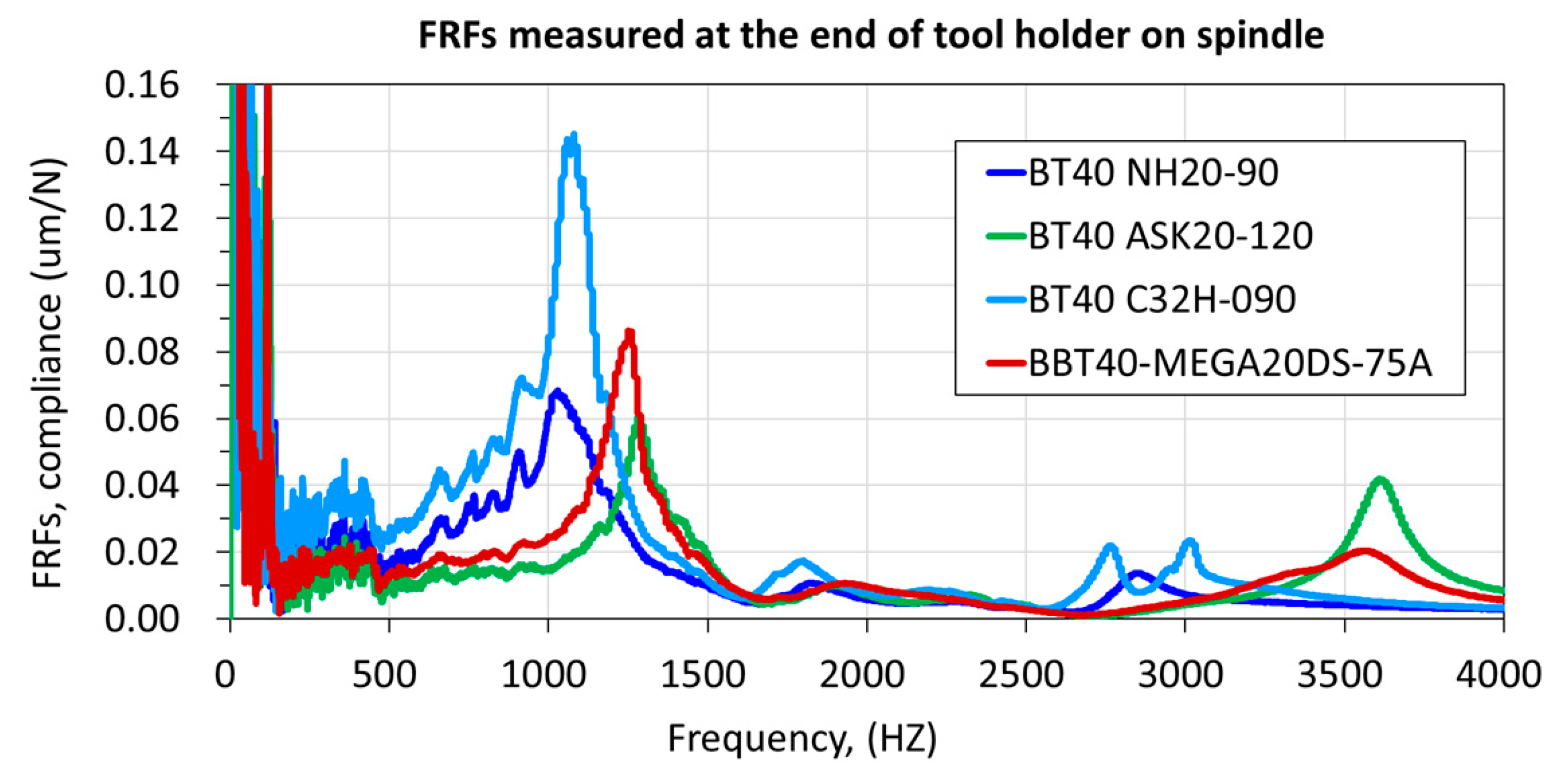
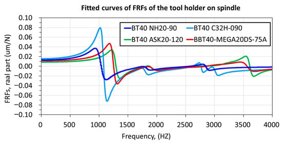
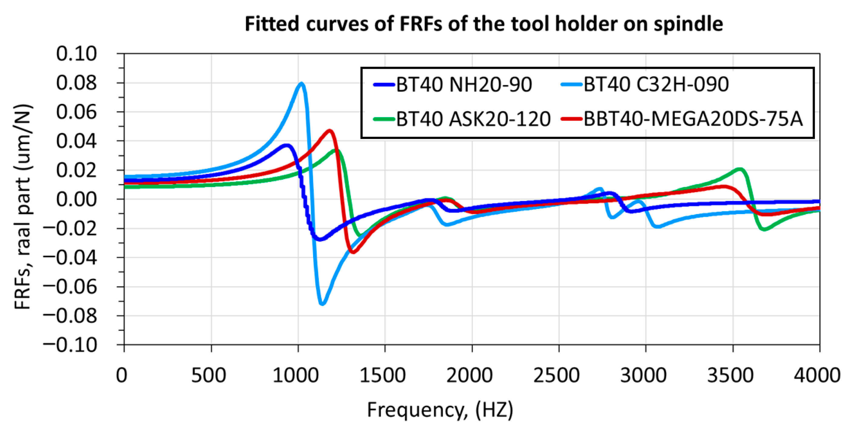
The FRFs (G11) measured at the end of each tool holder on the spindle are shown in Figure 7. This figure reveals that the spindle with a different tool holder demonstrated different dynamic characteristics with different compliance at different modes. The maximum compliance values of the spindle–tool system with TYPE-I, TYPE-II, and TYPE-III tool holders were 0.068 μm/N (1030 Hz), 0.058 μm/N (1290 Hz), and 0.150 μm/N (1080 Hz), respectively. The spindle–tool with the BBT holder had a maximum compliance of 0.086 μm/N at 1250 Hz. Moreover, the comparison of the modal-fitted curves of the original FRFs in Figure 8 demonstrates that the spindle–tool with the third BT holder (TYPE-III) showed a higher compliance at a lower frequency compared with the BBT holder, despite having a similar shank in its geometry. These results indicate that the type of tool holder greatly affected the dynamic characteristics of the spindle–tool system. The discrepancy was probably caused by the interface characteristics between the spindle nose and the tool holder.
Figure 7.
Frequency response functions (G11) measured at the end of each tool holder on the spindle.
Figure 8.
Comparisons of modal-fitted curves of experimentally measured FRFs of different tool holders.
4. Estimation of the Receptance Compliance Matrix
Within the receptance coupling procedure, the compliance matrices of the tool holder, including [HA11] and [HA12], as well as the spindle nose compliance matrix [HB22], appearing in Equation (9), are required. The general compliance matrix formulation comprises four subcomponents, as presented in Equations (6) and (7). For each substructure, the direct and cross-translational displacement–force components, such as Ha11 and Ha21, were experimentally identified via impact (tapping) tests performed on the milling machine. The remaining components, namely, La11, Na11, and Pa11, were obtained using the numerical procedure described in [25].
To lessen the approximation errors, this study applied the finite element method to calculate the compliance components associated with points 1 and 2 of the structures. The main procedures are stated as follows:
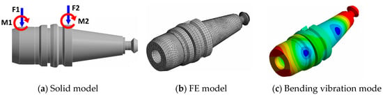
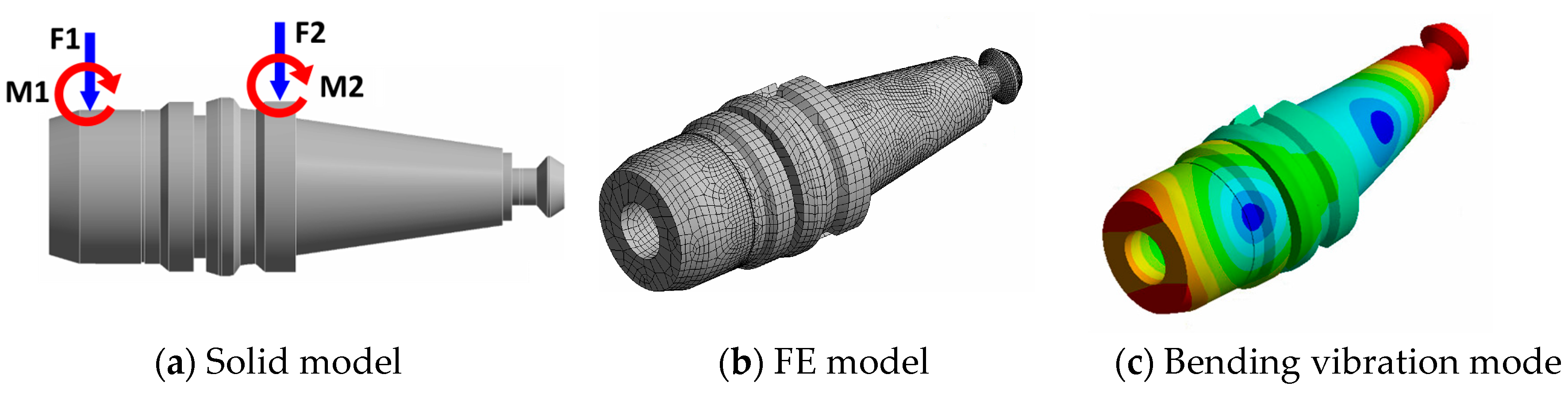
- The finite element model of the substructures was created, using the tool holder of the BBT type as an example, as shown in Figure 9.Figure 9. Finite model for predicting the compliance components of the tool holder.
- Harmonic analysis was conducted to predict the frequency response functions Ha11 and Ha22, which are linear displacements of points 1 and 2 under forces F1 and F2, as shown in Figure 9a.
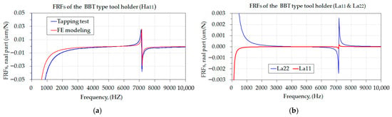
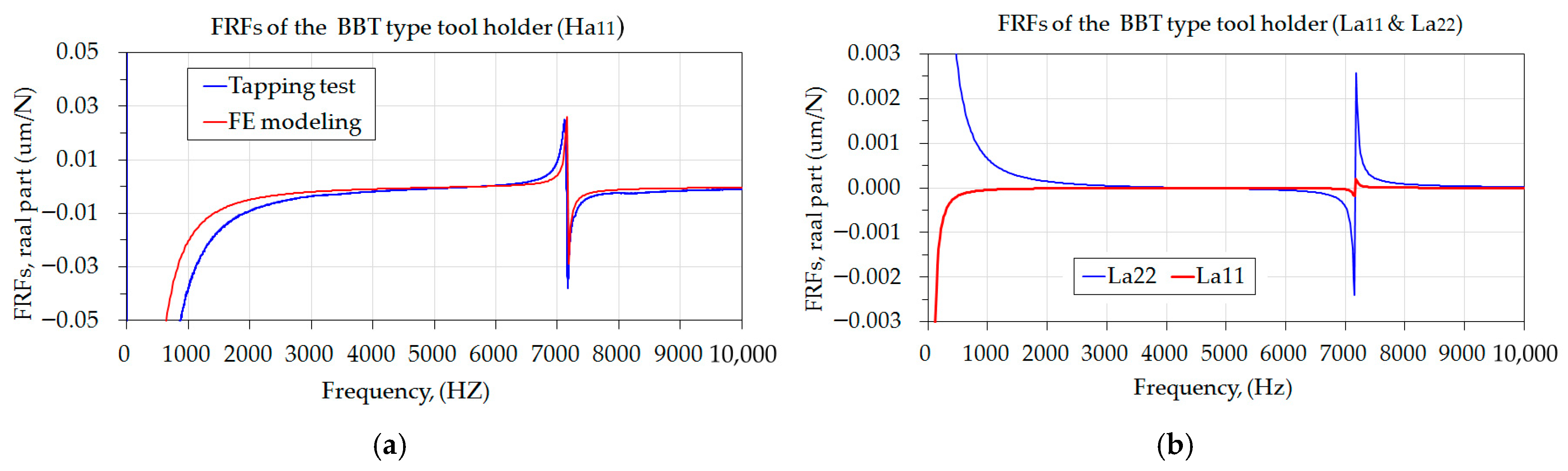
- The receptance components, the FRFs obtained from the finite element computation and tapping test, were compared to validate the finite element models. As shown in Figure 10a, the predicted FRFs of the tool holder agreed well with the measurements. Figure 9c illustrates the bending vibration of the tool holder at a frequency of around 7100 Hz, which dominated the FRF.Figure 10. Frequency response functions of the tool holder. (a) Comparison between finite element computations and tapping tests; (b) finite element-predicted FRFs (La11 and La22).
- Using the validated finite element model, compliance components, such as La11 and La22, which are related to the linear displacements of points 1 and 2 against the moments M1 and M2, were calculated via harmonic analysis, as shown in Figure 10b. After that, other terms, such as Na11 and Pa11, were obtained.
It is noted that the coupling interface was defined at the spindle holder clamping location (point 2 in Figure 1). Therefore, the receptance matrices and are consistently defined at the same coupling location, avoiding ambiguity associated with internal or mid-point excitation. As shown in Figure 9a, receptance components Ha22 and La22 can be obtained by conducting harmonic analysis under lateral force and bending moment respectively, which are applied at the interface endpoint DOFs.
In the finite element modeling, the tool holder was meshed using hexahedral and tetrahedral elements with a global element size of 3 to 4 mm, comprising 19,436 elements and 32,806 nodes in total, which ensured a convergent solution. The tool holder was made of structural steel with the following material properties: Young’s modulus E = 210 GPa, density ρ = 7700 kg/m3, and Poisson’s ratio μ = 0.30. In the modal and harmonic analysis, the model was assumed to be in a free–free state without any constraints to approximate a “free” state of the tool holder in the tapping tests, where it was suspended by very soft cords.
The computational efficiency of FEA depends on the balance between the mesh density, element type, and geometric complexity. To optimize this, our study employed eight-node tetrahedral elements to mesh various tool holder–tool assemblies. Convergence testing determined that a range of 35,000 to 50,000 nodes provided high accuracy with minimal processing time. On hardware featuring an Intel Core i9 CPU and 128 GB of RAM, each harmonic analysis (0–5000 Hz; 5 Hz increments) took less than 10 min. Assessing all necessary FRFs for a full RCSA operation required approximately one hour per module. This FEA-based approach proved significantly more effective than traditional tapping tests, especially when evaluating multiple tool holder configurations for RCSA.
5. Identification of Interface Characteristics
5.1. Inverse RCSA
Inverse receptance coupling procedures were employed to identify the dynamic interface characteristic matrix of the bonded interface between the tool holder and the spindle nose.
Equation (11) represents a matrix inverse operation in the frequency domain; individual FRF terms are transfer functions and are not treated as algebraic ratios. The terms [HA11], [HA21], [HA12], and [HA22] are compliance matrices of frequency response functions associated with the tool holder; [HB22] is the compliance matrix of the frequency response functions associated with the spindle nose; and [GT11] is the compliance matrix associated with the spindle–tool holder system.
Equation (10) is solved with [HAij] and [HB22] known, such that [ is the only unknown. No algebraic reconstruction of receptance components is performed; all required translational, rotational, and cross receptances are either directly measured or obtained from validated three-dimensional finite element models. Consequently, the inverse problem is well-posed, and the identified interface parameters are governed by physically consistent experimental and numerical data rather than algebraic assumptions.
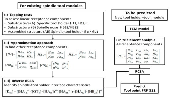
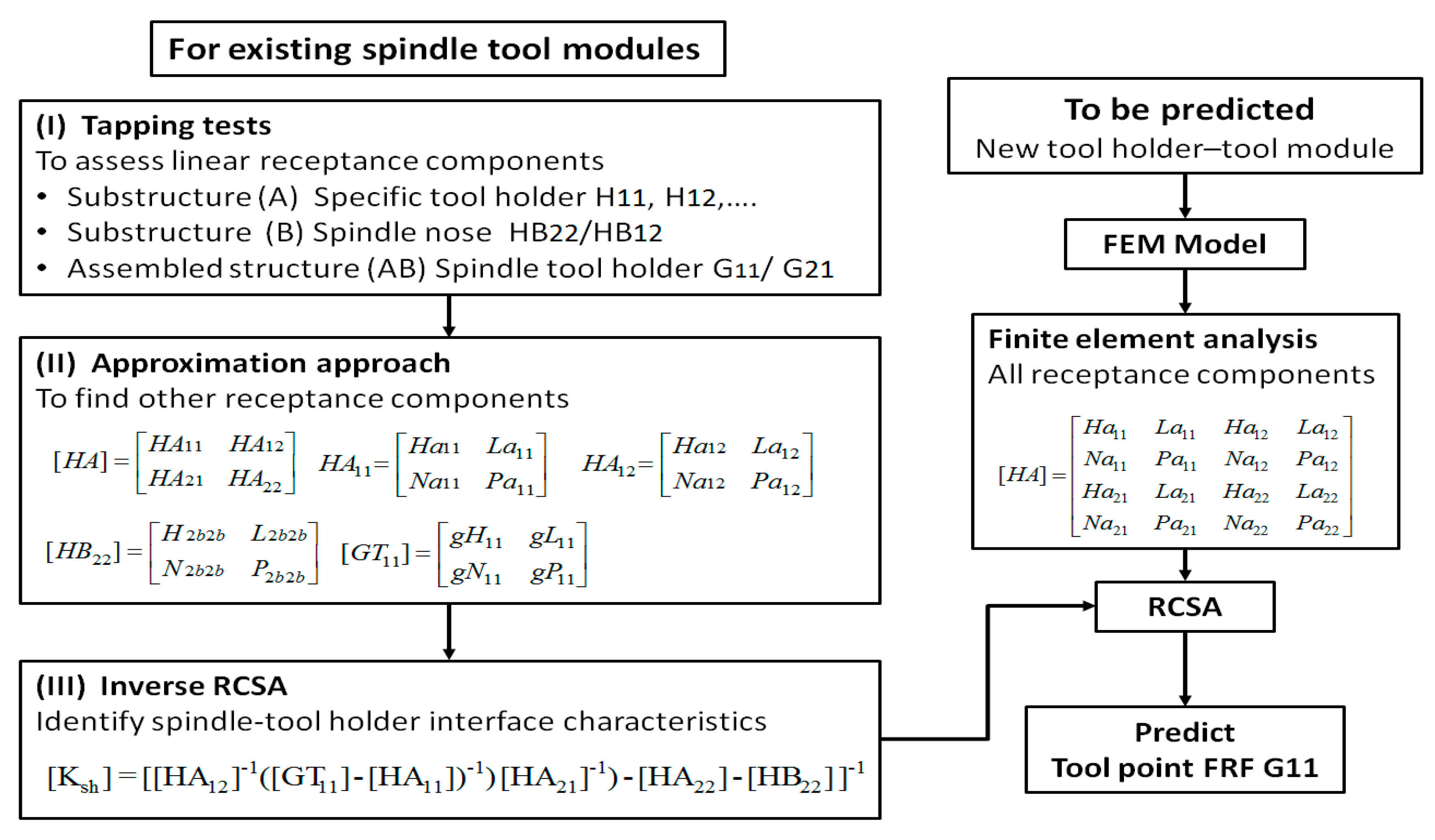
The interface characteristics between the substructures of the assembled structure can be identified from the compliance matrices of the substructures and the assembled structure via the following procedures, as shown in Figure 11. Using this algorithm, the assembled spindle–tool holder configuration was employed as the reference model in the inverse receptance coupling analysis to identify the interface dynamic characteristics. The identified interface properties were subsequently applied to predict the tool-end frequency response functions of tool holder–tool modules with different rod lengths installed in the milling spindle.
Figure 11.
Architecture of the interface characteristics’ identification between the spindle nose and the tool holder.
The inverse RCSA workflow is summarized below:
- (a)
- Define the interface DOFs: at the holder end (a2) and the spindle nose (b2).
- (b)
- Measure the assembly FRF for the spindle + holder (reference configuration).
- (c)
- Obtain the holder receptance matrices [HAij]: measured terms + FEM-derived terms (validated).
- (d)
- Obtain the spindle nose receptance [HB22] at B2 (from the reference configuration using inverse coupling).
- (e)
- Solve for the interface dynamic stiffness using the inverse coupling equation.
- (f)
- Apply with FEM-generated receptances of new holder–tool combinations to predict the tool-point FRFs.
Inverse RCSA becomes underdetermined if insufficient receptance components are available. In this study, this issue was addressed by supplementing experimental data with validated FEM-based receptances. Without such additional information, the identification of interface parameters would not be unique.
5.2. Interface Characteristics
The dynamic interface characteristics between the spindle nose and various types of tool holders are quantified and summarized in Table 1. For the BT40 NH20-90 tool holder, the linear translational stiffness and damping coefficient of the interface associated with the dominant vibration mode were N/m and 4100 N·s/m, respectively. For the BT40 ASK20-120 tool holder, the corresponding linear translational stiffness and damping coefficient were N/m and 8490 N·s/m, respectively. For the BT40 ASK20-120 tool holder, the interface exhibited a linear translational stiffness of N/m and a damping coefficient of 4930 N·s/m for the dominant mode.
Table 1.
Contact characteristics at the spindle–tool holder interface.
For the BBT40-MEGA20DS-75A tool holder, the linear translational stiffness and damping coefficient of the interface were 2.68 × 10⁷ N/m and 9830 N·s/m, respectively. The rotational stiffness and damping coefficients of the BT40 NH20-90 holder were 1.94 × 10⁷ Nm/rad and 530 Nm·s/rad, respectively. For the BT40 ASK20-120 tool holder, the rotational stiffness and damping coefficients were 0.89 × 10⁷ Nm/rad and 483 Nm·s/rad, respectively. For TYPE III, the rotational stiffness and damping coefficients were 1.16 × 10⁷ Nm/rad and 563 Nm·s/rad, respectively. For the BBT tool holder, the rotational stiffness and damping coefficients were 1.0 × 10⁷ Nm/rad and 832 Nm·s/rad, respectively.
The results show that the identified interface characteristics of the BT tool holders with various shanks were different and inconsistent, despite being designed with the same geometric tapered surface to be connected to the spindle nose taper, but with different shanks. This may be because the holder’s shank geometry slightly affected the frequency responses of the spindle holder. Furthermore, Table 1 demonstrates that the contact stiffness of the BBT tool holder was slightly higher than those of the BT-type tool holders, and it showed superior damping coefficients in the linear and rotational directions compared with the BT-type tool holders. Considering the similar geometrical constructions of the holders, BT Type I and BBT type had comparable interface characteristics, enabling them to demonstrate a similar frequency response when inserted into the spindle.
6. Application of RCSA for Prediction of Tool-Point FRFs
The tool-point FRFs of the milling spindle with different tool specifications could be predicted based on the identified interface characteristics. In this prediction, the four-flute cutter had a diameter of 20 mm and a length of 100 mm, which was clamped in the BT tool holder (collet ER32) with overhang lengths of 68, 73, and 78 mm, respectively. To predict the tool-point FRFs [GT11], the compliance matrices required for coupling operation in Equation (9) are given as follows. [HB22] is a compliance matrix of frequency response functions associated with the spindle nose, which is given in Section 3.
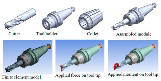
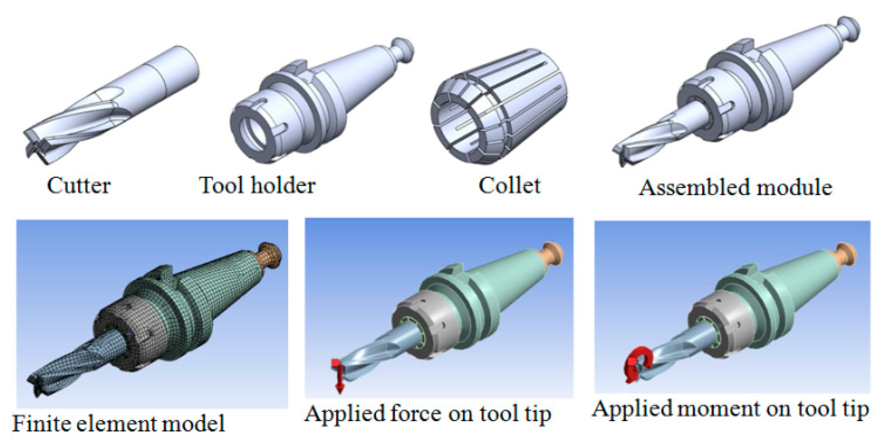
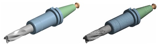
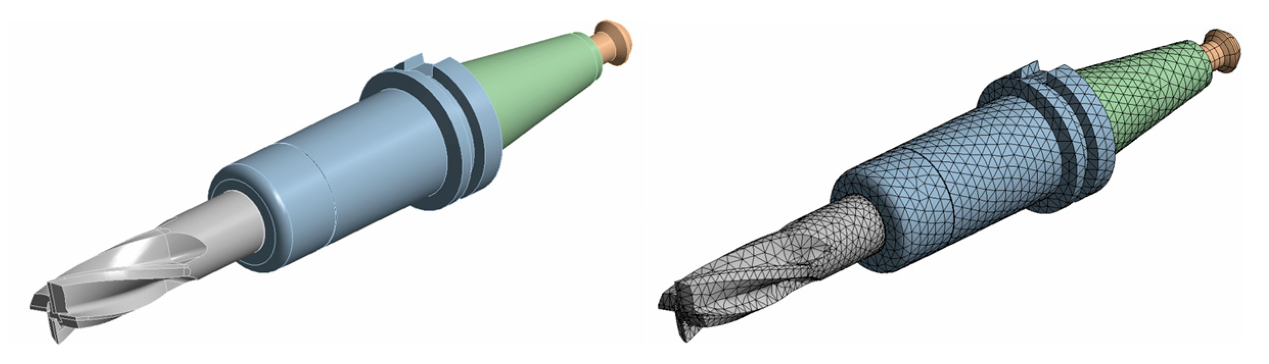
The terms [HA11], [HA21], [HA12], and [HA22] are compliance matrices of frequency response functions associated with a specific tool holder–tool assembly. The receptance components in the compliance matrix [HA11], including Ha11, La11, and La21, were obtained from finite element modeling, instead of the tapping tests. For this, the 3D solid model and finite element models of different tool holder–cutter modules were first created, as shown in Figure 12.
Figure 12.
Finite element models of tool holder–tool module.
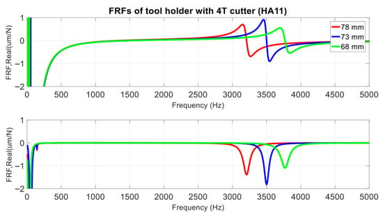
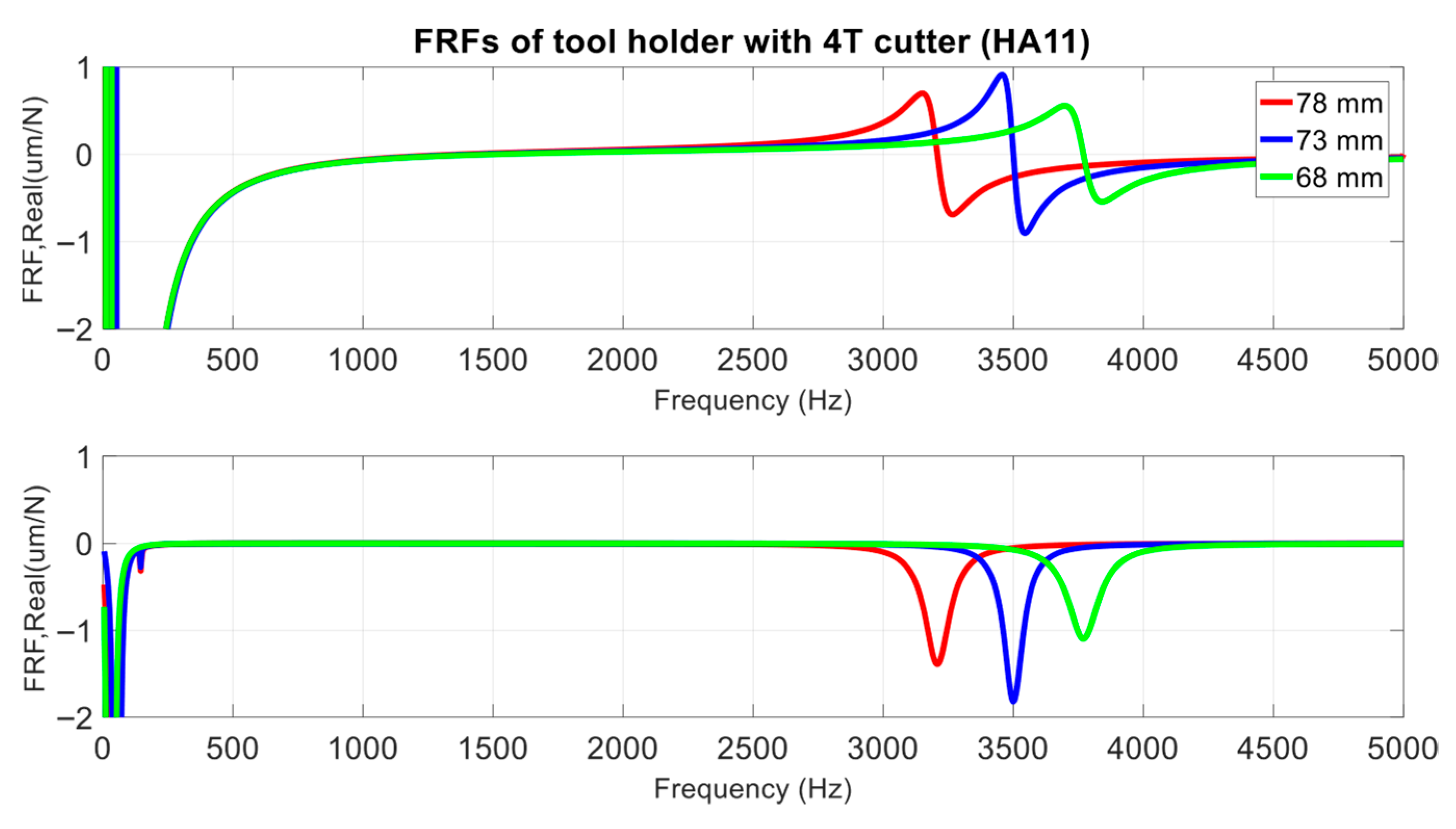
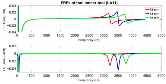
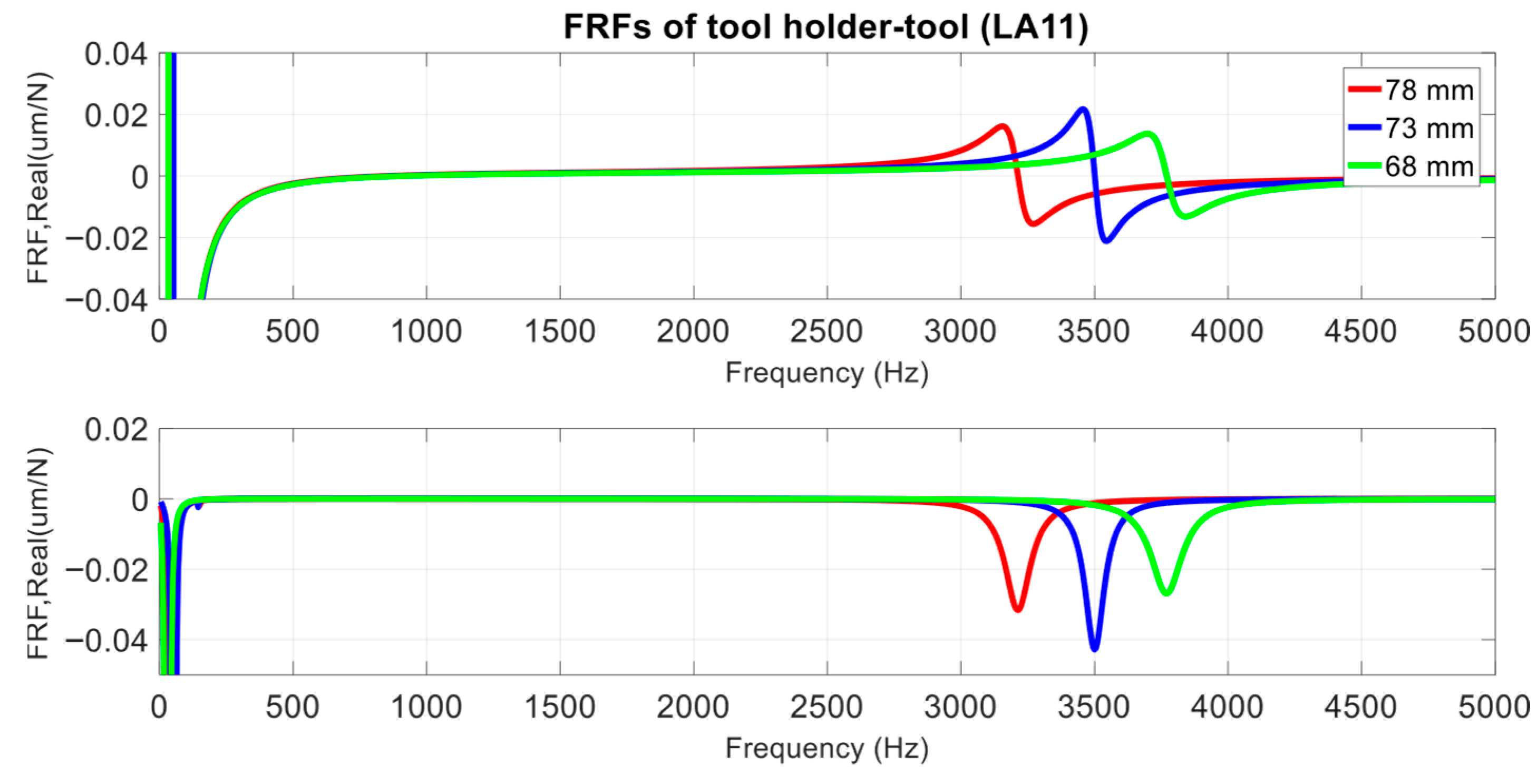
These models were validated by comparing the FRFs measured from vibration tests and finite element harmonic analysis. The linear and angular displacement compliances associated with the forces and moments, respectively, were predicted for subsequent coupling analysis using the validated models. Details for assessing the receptance compliance matrices of tool holder–tool modules are available in a previous study [33]. Figure 13, Figure 14 and Figure 15 illustrate the FRFs (Ha11, La11, and La21) of the holder–cutter with overhang lengths of 68, 73, and 78 mm, respectively. Ha11 represents the receptance components associated with the linear displacement to the force. La11 and La21 are the linear displacements to the moment applied at the tool end.
Figure 13.
FRFs (Ha11) of the tool holder–tool modules with different overhangs.
Figure 14.
FRFs (La11) of the tool holder–tool modules with different overhangs.
Figure 15.
FRFs (La21) of the tool holder–tool modules with different overhangs.
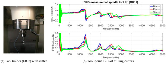
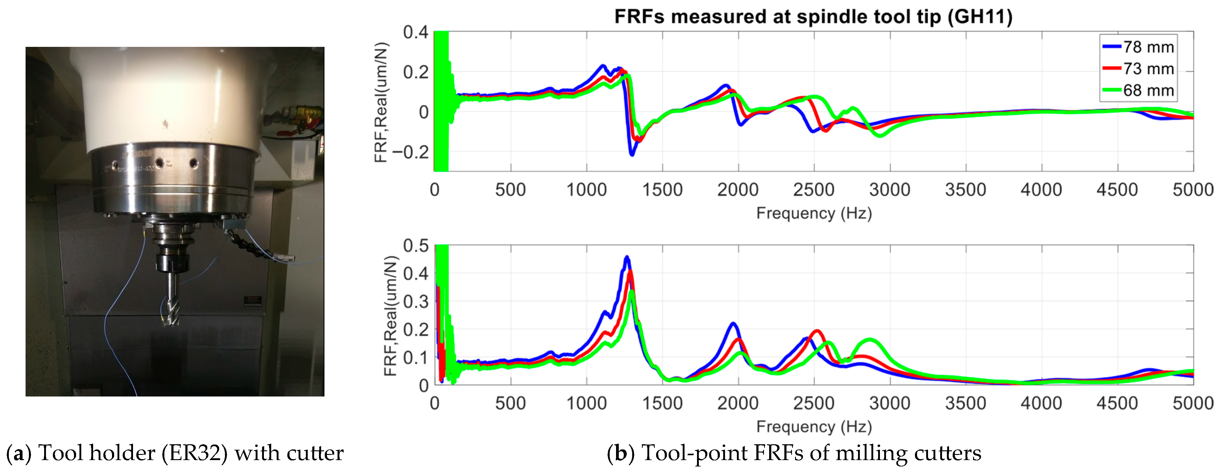
For the final validation of the coupling prediction of the tool-point FRFs, tapping tests were conducted on the spindle–tool system, which was clamped in the BT tool holder with overhangs of 68, 73, and 78 mm, respectively, as shown in Figure 16a. The FRFs (GH11) measured at the tool end of the spindle system are illustrated in Figure 16b. GH11 was associated with the linear displacement of the spindle–tool system excited by the force applied at the tool end. As observed in Figure 16b, the maximum compliance values at the dominant mode were 0.3348 μm/N (at 1296 Hz), 0.4077 μm/N (at 1288 Hz), and 0.4574 μm/N (at 1266 Hz) for cutters with overhangs of 68, 73, and 78 mm, respectively. The clamped range of the milling cutter in the tool holder significantly influenced the modal characteristics that dominated the machining stability of the machine tool. This also suggested that adjusting the tool’s overhang length could improve the cutter’s dynamic characteristics to obtain a more stable machining region with a higher material removal rate [38].
Figure 16.
FRFs (GH11) measured at tool end of milling cutters with different overhang lengths: (a) tapping test; (b) tool-point FRFs.
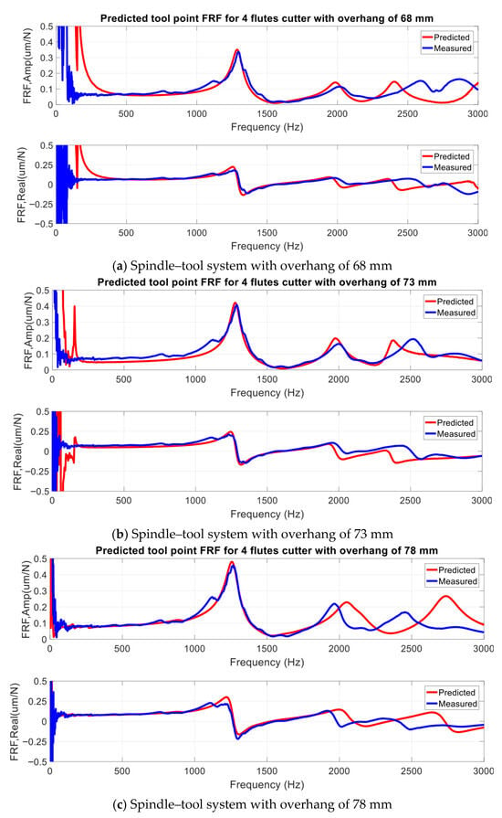
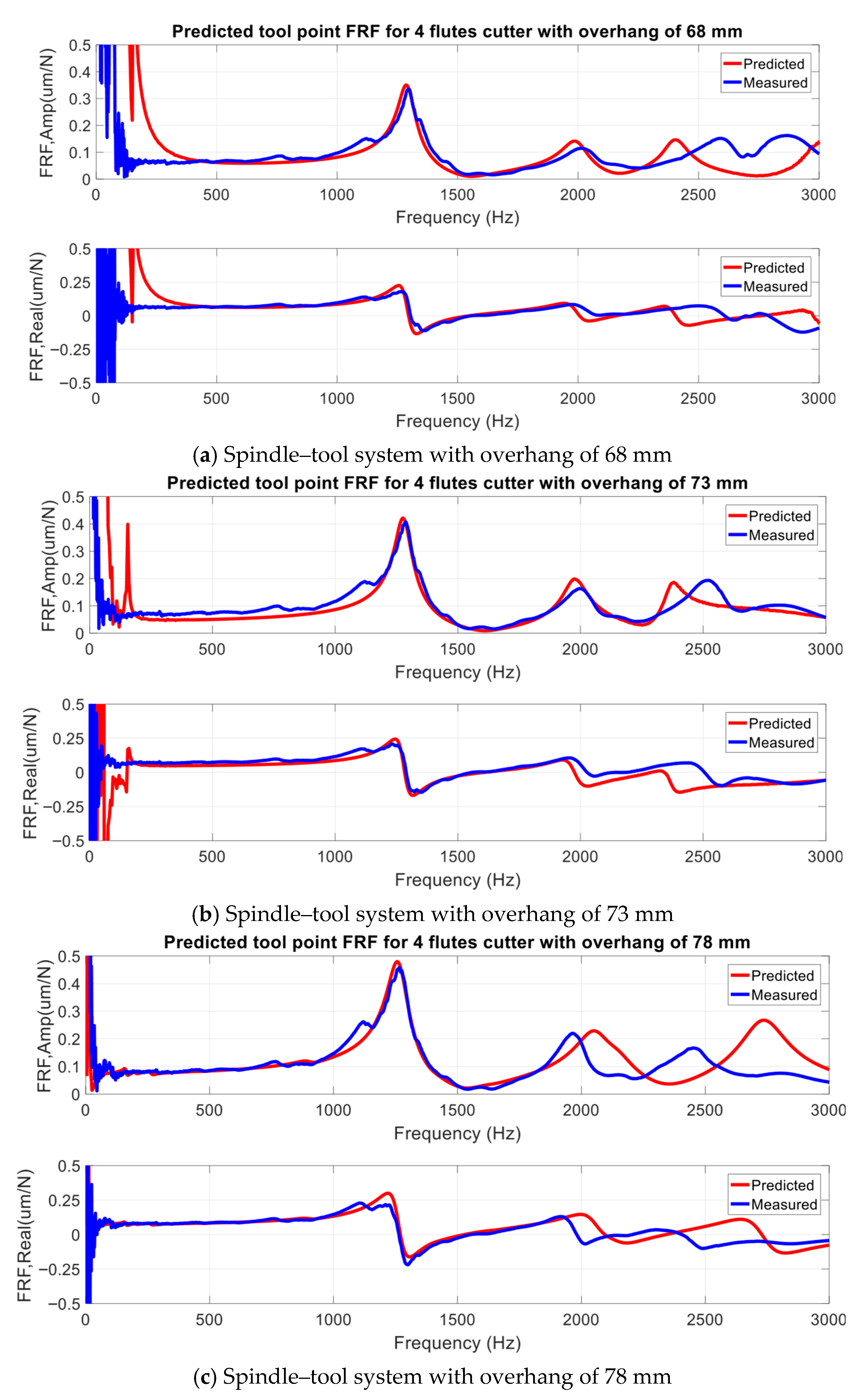
The tool-end frequency response functions (FRFs) of the spindle–tool system with different tool specifications were subsequently predicted based on the identified interface characteristics using the RCSA algorithm illustrated in Figure 11. Figure 17 presents the predicted tool-point FRFs () of the spindle–tool system equipped with four-flute cutters with overhang lengths of 68, 73, and 78 mm, respectively. The predicted FRFs showed good agreement with the experimental results obtained from vibration tests conducted on the milling cutters.
Figure 17.
The RCSA-predicted tool-point FRFs (G11) of the spindle–tool system with different tooling conditions.
As summarized in Table 2, for different tool clamping lengths, the dominant natural frequencies predicted by the receptance coupling operation closely match the measured values, with discrepancies of less than 3.2%. This result clearly indicates that the vibration behavior of the assembled structure was predominantly governed by the tool holder–tool interface. In contrast, the difference between the predicted and measured tool compliance ranged from 3% to 6.4%. These discrepancies can be primarily attributed to variations in the actual contact characteristics, including contact stiffness and interface damping between the spindle and tool holder, which may slightly change with different tool overhang lengths. Nevertheless, the results suggest that the interface characteristics identified in this study are only marginally influenced by tool holder geometry, implying relatively limited variation in the contact interface properties.
Table 2.
Comparisons of the modal parameters of tool-point FRFs obtained using tapping test and RCSA predictions.
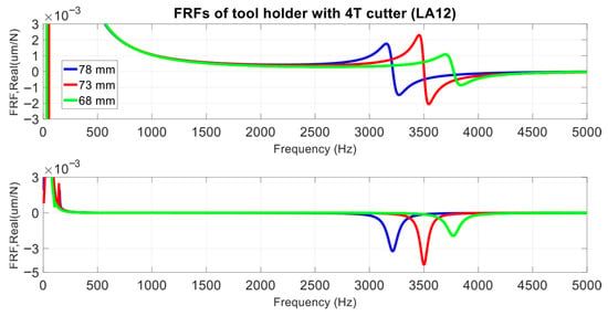
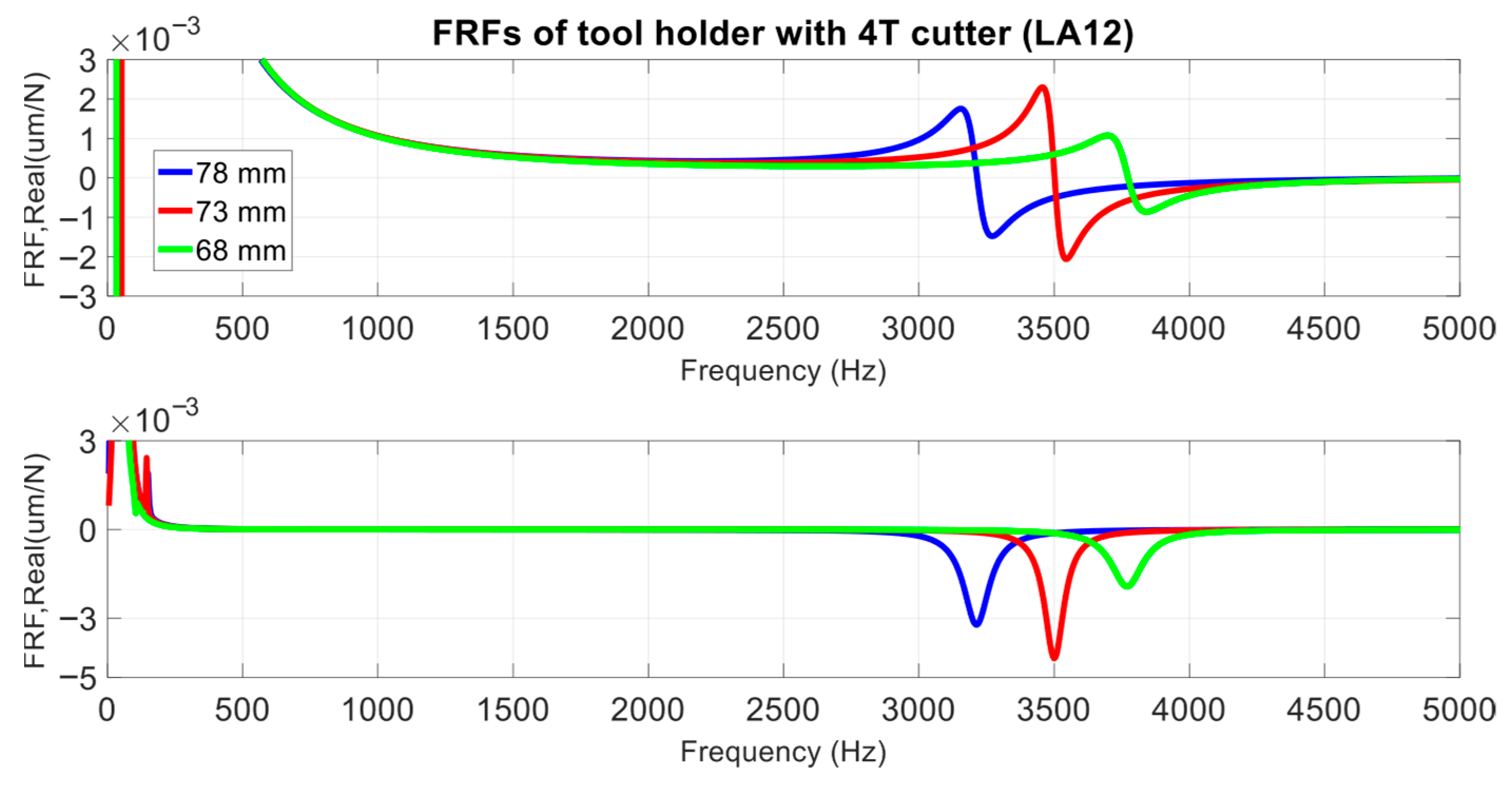
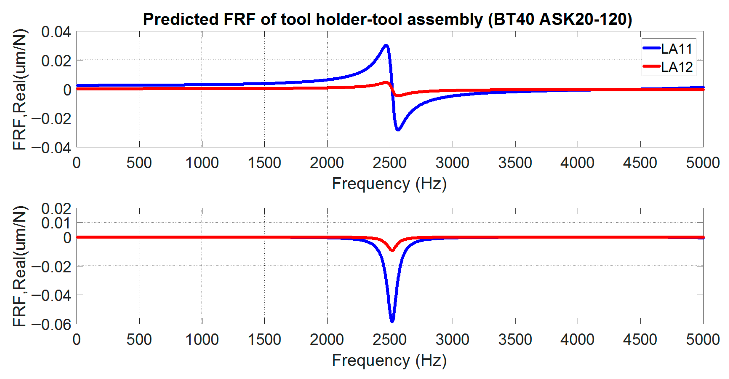
Another case is presented to demonstrate the application of RCSA with FE modeling for predicting tool-tip FRFs. As shown in Figure 18, the BT40-ASK20-120 tool holder (Type II) had a longer shank overhang of 120 mm compared with the BT Type III tool holder with an E32 collet. The measured FRFs (Figure 4 and Figure 5) revealed that the FRFs of the BT40-ASK20-120 tool holder were more flexible than those of the BT40 C32H-090 tool holder (Type III). A four-flute cutter with a diameter of 20 mm and a length of 100 mm was clamped in the holder with an overhang length of 78 mm. We created a 3D model and a finite element model, which was meshed with a tetrahedral element with a mesh size of 3 mm, to predict the FRF of the tool holder–tool when mounted on the milling spindle. The receptance components of the substructure B (tool holder–tool assembly) were obtained by conducting the harmonic analysis under direct force and moment loadings, respectively. The FRFs associated with displacement responses (LA11 and LA12) of the cutter endpoint under moment loading are shown in Figure 19.
Figure 18.
Finite element model of tool holder (BT40 ASK20-120) with cutter.
Figure 19.
FRFs associated with displacement responses (LA11 and LA12) at endpoint of cutter under moment loading.
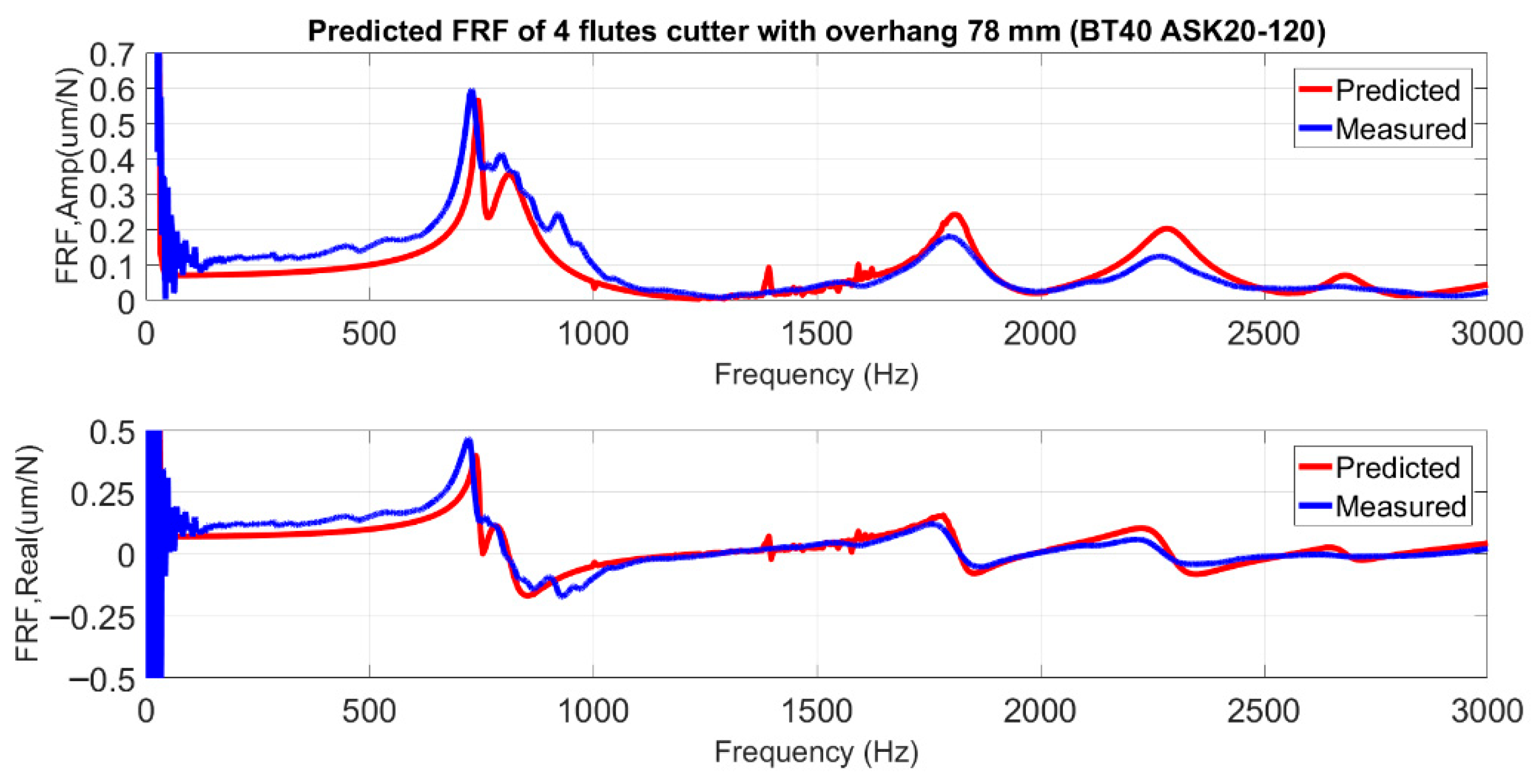
The endpoint FRF of the spindle–tool holder–tool assembly was obtained using the proposed method and is illustrated in Figure 20, in which the measured FRF is depicted for comparison. The coupling prediction was compatible with the tapping test measurement. The maximum compliance and frequency of the predicted and measured FRFs were 0.5964 μm/N at 728 Hz and 743 0.5651 μm/N at 743 Hz, respectively, with a difference of approximately 5.2%. In these case studies, different combinations of the holder–tool assembly were used to validate the proposed method in predicting the tool-tip FRFs when mounted on the milling spindle. The accuracy of RCSA with FE modeling was affected by the holder–tool interface characteristics to some extent, which changed with the holder geometry and the receptance components, as well as the FRFs obtained via FEA, which required the model to resemble the real one.
Figure 20.
Comparison of endpoint FRFs of spindle–tool holder–tool assembly predicted using RCSA and measurements.
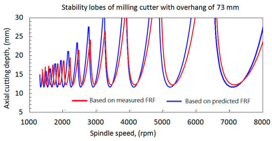
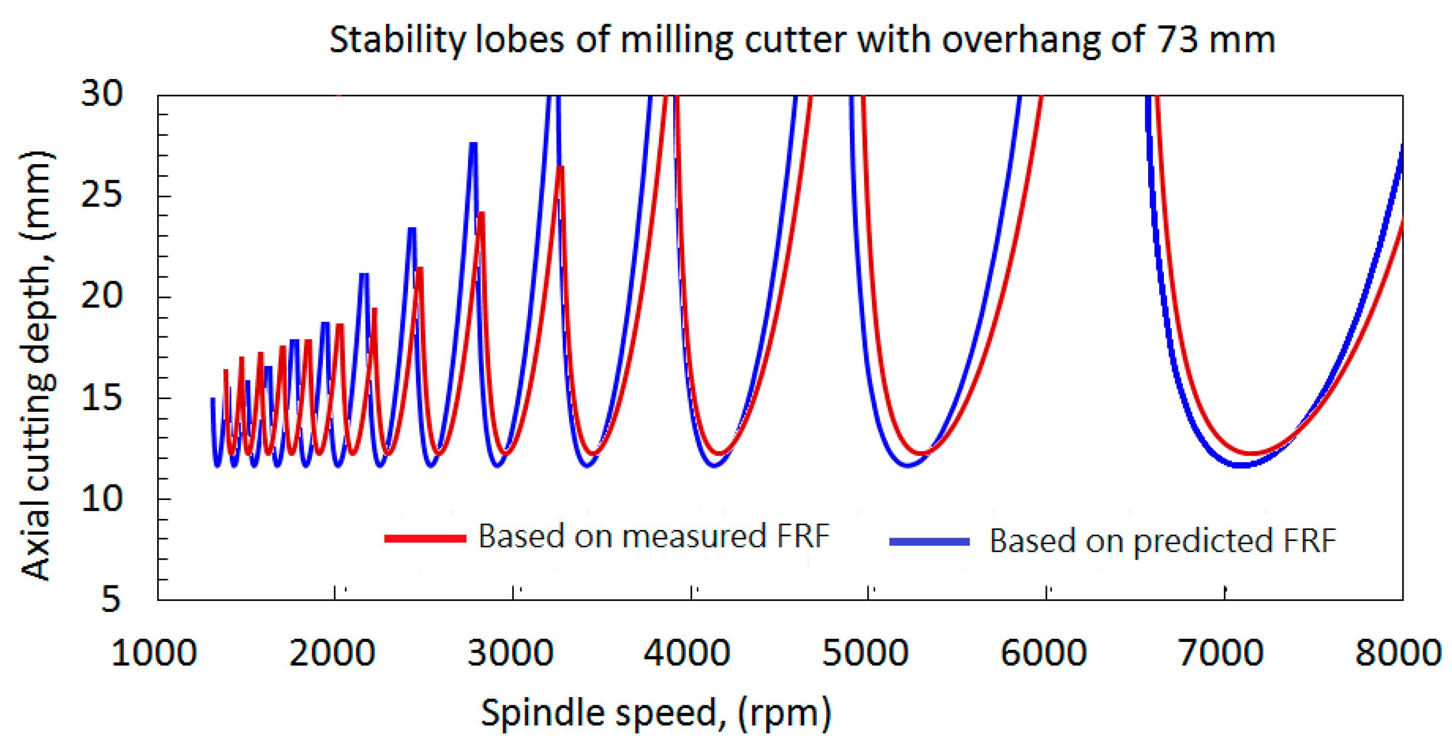
The tool-point FRFs can be used to visualize the machining stability of the milling tool. Taking the cutter with an overhang of 73 mm as an example, the stability diagrams were evaluated based on the experimentally measured and RCSA-predicted FRFs at the dominant mode at approximately 1288 Hz, as illustrated in Figure 21 for comparison. In the calculation of the machining stability [39], the cutting force coefficients of the carbide tool against Al6060T6 alloys were calibrated as Kt = 800 N/mm2 [40,41]. Figure 16 shows that the stability lobes assessed with the predicted FRF showed good agreement with those assessed with the measured FRF, with a difference of approximately 5% in the axial-limited cutting depth. Therefore, the results show that implementing the identification of the spindle–tool holder interface characteristics in the receptance coupling method can effectively predict the tool-point frequency response functions of a milling spindle with different tooling conditions, which also provides an efficient and accurate method to evaluate the machining stability of a milling cutter.
Figure 21.
Comparisons of the stability lobes based on the experimentally measured and RCSA-predicted FRFs, respectively.
This study confirmed that accurate identification of spindle nose–tool holder interface characteristics is critical for reliable tool-point FRF prediction. Both translational and rotational interface stiffness and damping were identified by applying inverse RCSA, resulting in close agreement between predicted and measured tool compliances, with errors limited to 3–6.4%. A major strength of the proposed approach is the hybrid experimental–numerical strategy. Experimental tapping tests are required only for reference assemblies, while full 3D finite element modeling is used to generate complete receptance matrices for tool holder–tool substructures. Compared with beam theory- or simplified artifact-based models, the 3D FEM approach enables accurate representation of complex holder geometries, realistic mass and stiffness distributions, and flexible tool holder combinations without additional analytical assumptions. This contributes directly to improved prediction fidelity, particularly for bending-dominated vibration modes.
The comparative analysis of BT and BBT tool holders demonstrates that interface design significantly affects dynamic behavior. BBT holders generally exhibit higher contact stiffness and damping, leading to reduced compliance amplitudes and improved dynamic stability. The similarity observed between BT Type I and BBT holders further indicates that subtle geometric differences can result in comparable interface dynamics, underscoring the importance of quantitative interface characterization. In contrast with free–free tool FRF prediction methods and inverse RCSA approaches based on simplified artifacts, the present framework explicitly targets assembled spindle–tool systems under practical machining conditions. Reusing identified spindle holder interface parameters and combining them with FEM-generated tool receptance enables tool-point FRFs to be efficiently predicted for multiple tooling configurations without repeated system-level testing. In addition, it is worthy to note that dummy-tool-based procedures reported in the literature [40] are particularly suited to configurations in which the holder shank geometry remains unchanged and only tool length or diameter varies. In contrast, by defining the coupling interface at the spindle holder clamping location (point 2 in Figure 1), the proposed inverse RCSA framework enables reuse of the identified interface dynamics across tool holders with different shank geometries. This interface-based formulation therefore provides greater generality for practical industrial tooling systems.
Although the proposed method showed strong performance, interface characteristics were identified under fixed assembly conditions, and the effects of variable clamping force, thermal loading, and nonlinear contact behavior were not considered. Future work will address these factors and extend the approach to other holder systems and machining configurations. Despite its advantages, several limitations should be noted. The identified interface characteristics correspond to specific assembly and clamping conditions, and variations in drawbar force, thermal effects, and interface wear were not explicitly considered. In addition, the FEM models assume linear elastic behavior at the interfaces, whereas nonlinear contact phenomena may arise under severe cutting loads. Future work will focus on incorporating variable clamping forces, nonlinear interface effects, and thermal influences, as well as extending the framework to other holder systems and multi-axis machining configurations.
7. Conclusions
This study presents an effective and practical framework for predicting tool-point frequency response functions (FRFs) of spindle–tool systems by explicitly characterizing the dynamic interface between the spindle nose and the tool holder. An inverse receptance coupling substructure analysis (RCSA) method was employed to identify both translational and rotational stiffness and damping parameters at the spindle holder interface, while finite element modeling (FEM) was used to generate complete receptance matrices for tool holder–tool assemblies. The proposed approach achieved high prediction accuracy, with differences between predicted and measured tool compliances limited to 3–6.4%.
The key novelty of this work lies in shifting the focus of FRF prediction from tool-only or tool holder interfaces to the spindle nose–tool holder interface, which is a major yet often overlooked source of variability in practical milling systems. In addition, the adoption of full 3D FEM for tool holders enables accurate representation of complex geometries and flexible tool holder combinations, overcoming the limitations of beam theory-based or simplified artifact models commonly used in previous studies.
The comparative investigation of BT and BBT tool holders further demonstrates that interface design significantly influences contact stiffness, damping, and dynamic compliance, directly affecting machining stability. By reusing the identified interface parameters, the proposed framework allows efficient FRF prediction for multiple tooling configurations without repeated system-level experimental testing. Overall, this study provides a robust, general, and industrially relevant methodology for dynamic characterization and stability prediction of spindle–tool systems, offering valuable support for process planning and performance optimization in high-speed milling applications.
Author Contributions
Conceptualization and methodology, W.-Z.L. and J.-P.H.; software and formal analysis, W.-Z.L., Y.-C.L. and X.-J.X.; investigation, W.-Z.L., Y.-C.L., X.-J.X. and Y.-S.L.; resources, J.-P.H.; data curation, W.-Z.L., Y.-C.L., X.-J.X., and Y.-S.L.; writing—original draft preparation, W.-Z.L., Y.-C.L. and J.-P.H.; writing—review and editing, J.-P.H.; visualization, W.-Z.L.; supervision, J.-P.H.; project administration, J.-P.H.; funding acquisition, J.-P.H. All authors have read and agreed to the published version of the manuscript.
Funding
This research was funded by the National Science and Technology Council, Taiwan, under grant numbers NSTC 111-2622-167-017.
Data Availability Statement
The data are contained within this article.
Conflicts of Interest
The authors declare no conflicts of interest.
References
- Tobias, S.A. Machine-Tool Vibration; Blackie & Son Ltd.: Glasgow, UK, 1965. [Google Scholar]
- Tlusty, J. Manufacturing Processes and Equipment; Prentice Hall: Hoboken, NJ, USA, 2000. [Google Scholar]
- Choi, J.K.; Lee, D.G. Characteristics of spindle bearing system with a gear located on the bearing span. Int. J. Mach. Tools Manuf. 1994, 37, 171–181. [Google Scholar] [CrossRef] [Scilit]
- BIG-PLUS Tooling System. Available online: https://www.bigdaishowa.eu/en/products/tool-holders/milling-chucks.html (accessed on 30 May 2023).
- Agapiou, J.; Rivin, E.; Xie, C. Toolholder/spindle interfaces for CNC machine tools. CIRP Ann. Manuf. Technol. 1995, 44, 383–387. [Google Scholar] [CrossRef] [Scilit]
- Smith, S.; Jacobs, P.; Halley, J. The effect of drawbar force on metal removal rate in milling. CIRP Ann. Manuf. Technol. 1999, 48, 293–296. [Google Scholar] [CrossRef] [Scilit]
- Rivin, E. Influence of tool holder interfaces on tooling performance. Trans. NAMRV/SME 1993, 21, 173–179. [Google Scholar]
- Weck, M.; Schubert, I. New interface machine/tool: Hollow shank. CIRP Ann. Manuf. Technol. 1994, 43, 345–348. [Google Scholar] [CrossRef] [Scilit]
- Schmitz, T.L.; Davies, M.A.; Medicus, K.; Snyder, J. Improving high-speed machining material removal rates by rapid dynamic analysis. CIRP Ann. Manuf. Technol. 2001, 50, 263–268. [Google Scholar] [CrossRef] [Scilit]
- Schmitz, T.L.; Donalson, R.R. Predicting high-speed machining dynamics by substructure analysis. CIRP Ann. Manuf. Technol. 2000, 49, 303–308. [Google Scholar] [CrossRef] [Scilit]
- Schmitz, T.L.; Davies, M.; Kennedy, M. Tool point frequency response prediction for high-speed machining by RCSA. J. Manuf. Sci. Eng. Trans. ASME 2001, 123, 700–707. [Google Scholar] [CrossRef] [Scilit]
- Ertürk, A.; Budak, E.; Özgüven, H.N. Selection of design and operational parameters in spindle–holder–tool assemblies for maximum chatter stability by using a new analytical model. Int. J. Mach. Tools Manuf. 2007, 47, 1401–1409. [Google Scholar] [CrossRef] [Scilit]
- Xu, C.; Feng, P.; Zhang, J.; Yu, D.; Wu, Z. Milling stability prediction for flexible workpiece using dynamics of coupled machining system. Int. J. Adv. Manuf. Technol. 2017, 90, 3217–3227. [Google Scholar] [CrossRef] [Scilit]
- Kiran, K. A receptance coupling procedure considering frequency-dependent behavior of holder-tool contact dynamics. J. Manuf. Process. 2022, 80, 624–641. [Google Scholar] [CrossRef] [Scilit]
- Park, S.S.; Altintas, Y.; Movahhedy, M. Receptance coupling for end mills. Int. J. Mach. Tools Manuf. 2003, 43, 889–896. [Google Scholar] [CrossRef] [Scilit]
- Albertelli, P.; Goletti, M.; Monno, M.A. A new receptance coupling substructure analysis methodology to improve chatter free cutting conditions prediction. Int. J. Mach. Tools Manuf. 2013, 72, 16–24. [Google Scholar] [CrossRef] [Scilit]
- Mancisidor, I.; Urkiola, A.; Barcena, R.; Munoa, J.; Dombovari, Z.; Zatarain, M. Receptance coupling for tool point dynamic prediction by fixed boundaries approach. Int. J. Mach. Tools Manuf. 2014, 78, 18–29. [Google Scholar] [CrossRef] [Scilit]
- Ahmadi, K.; Ahmadian, H. Modeling machine tool dynamics using a distributed parameter tool–holder joint interface. Int. J. Mach. Tools Manuf. 2007, 47, 1916–1928. [Google Scholar] [CrossRef] [Scilit]
- Ertürk, A.; Özgüven, H.N.; Budak, E. Analytical modeling of spindle–tool dynamics on machine tools using Timoshenko beam model and receptance coupling for the prediction of tool point FRF. Int. J. Mach. Tools Manuf. 2006, 46, 1901–1912. [Google Scholar] [CrossRef] [Scilit]
- Özşahin, O.; Ertürk, A.; Özgüven, H.N.; Budak, E. A closed-form approach for identification of dynamical contact parameters in spindle–holder–tool assemblies. Int. J. Mach. Tools Manuf. 2009, 49, 25–35. [Google Scholar] [CrossRef] [Scilit]
- Schmitz, T.L.; Powell, K.; Won, D.; Duncan, G.S.; Sawyer, W.G.; Ziegert, J.C. Shrink fit tool holder connection stiffness/damping modeling for frequency response prediction in milling. Int. J. Mach. Tools Manuf. 2007, 47, 1368–1380. [Google Scholar] [CrossRef] [Scilit]
- Budak, E.; Ertürk, A.; Özgüven, H.N. A modeling approach for analysis and improvement of spindle-holder-tool assembly dynamics. CIRP Ann. Manuf. Technol. 2006, 55, 369–372. [Google Scholar] [CrossRef] [Scilit]
- Ertürk, A.; Özgüven, H.N.; Budak, E. Effect analysis of bearing and interface dynamics on tool point FRF for chatter stability in machine tools by using a new analytical model for spindle–tool assemblies. Int. J. Mach. Tools Manuf. 2007, 47, 23–32. [Google Scholar] [CrossRef] [Scilit]
- Namazi, M.; Altintas, Y.; Abe, T.; Rajapakse, N. Modeling and identification of tool holder–spindle interface dynamics. Int. J. Mach. Tools Manuf. 2007, 47, 1333–1341. [Google Scholar] [CrossRef] [Scilit]
- Schmitz, T.L.; Duncan, G.S. Three-component receptance coupling substructure analysis for tool point dynamics prediction. J. Manuf. Sci. Eng. Trans. ASME 2005, 127, 781–790. [Google Scholar] [CrossRef] [Scilit]
- Yin, Q.; Dong, G.; Yin, G.; Heng, L.; Wang, L. Research on modeling and identification of machine tool joint dynamic characteristics. J. Adv. Mech. Des. Syst. Manuf. 2019, 13, JAMDSM0046. [Google Scholar] [CrossRef] [Scilit]
- Sulitka, M.; Falta, J.; Kohut, P. Single artifact inverse RCSA with improved cross compliance identification. Int. J. Adv. Manuf. Technol. 2024, 134, 5413–5429. [Google Scholar] [CrossRef] [Scilit]
- Grossi, N.; Scippa, A.; Montevecchi, F.; Campatelli, G. A novel experimental-numerical approach to modeling machine tool dynamics for chatter stability prediction. J. Adv. Mech. Des. Syst. Manuf. 2016, 10, JAMDSM0019. [Google Scholar] [CrossRef] [Scilit]
- Montevecchi, F.; Grossi, N.; Scippa, A.; Campatelli, G. Improved RCSA technique for efficient tool-tip dynamics prediction. Precis. Eng. 2016, 44, 152–162. [Google Scholar] [CrossRef] [Scilit]
- Liao, J.; Yu, D.; Zhang, J.; Feng, P.; Wu, Z. An efficient experimental approach to identify tool point FRF by improved receptance coupling technique. Int. J. Adv. Manuf. Technol. 2018, 94, 1451–1460. [Google Scholar] [CrossRef] [Scilit]
- Ji, Y.; Bi, Q.; Zhang, S.; Wang, Y. A new receptance coupling substructure analysis methodology to predict tool tip dynamics. Int. J. Mach. Tools Manuf. 2018, 126, 18–26. [Google Scholar] [CrossRef] [Scilit]
- Hung, J.P.; Wu, K.D.; Lin, W.Z.; Shih, W.C. Analyzing the dynamic characteristics of milling tool using finite element method and receptance coupling method. Eng. Technol. Appl. Sci. Res. 2019, 9, 3918–3923. [Google Scholar] [CrossRef] [Scilit]
- Xuan, X.J.; Haung, Z.H.; Wu, K.D.; Hung, J.P. Prediction of the frequency response function of a tool holder-tool assembly based on receptance coupling method. Eng. Technol. Appl. Sci. Res. 2018, 8, 3556–3560. [Google Scholar] [CrossRef] [Scilit]
- Zhao, D.; Li, X.; Wan, S.; Zhao, Q.; Hong, J. A novel method for identifying tool–holder interface dynamics based on receptance coupling. Machines 2024, 12, 911. [Google Scholar] [CrossRef] [Scilit]
- Chaux, J.D.; Osoro, P.X.A.; Arrazola, P.J. A novel computational approach using receptance coupling substructure analysis for prediction of tool tip dynamics in industrial machining applications. Int. J. Mach. Tools Manuf. 2025, 209, 104296. [Google Scholar] [CrossRef] [Scilit]
- Schmitz, T. Modal interactions for spindle, holders, and tools. Procedia Manuf. 2020, 48, 457–465. [Google Scholar] [CrossRef] [Scilit]
- Postel, M.; Özsahin, O.; Altintas, Y. High speed tooltip FRF predictions of arbitrary tool-holder combinations based on operational spindle identification. Int. J. Mach. Tools Manuf. 2018, 129, 48–60. [Google Scholar] [CrossRef] [Scilit]
- Park, S.S.; Amani, S.; Lee, D.Y.; Lee, J.; Nam, E. Machine learning based substructure coupling of machine tool dynamics and chatter stability. CIRP Ann. Manuf. Technol. 2024, 73, 297–300. [Google Scholar] [CrossRef] [Scilit]
- Altintas, Y.; Budak, E. Analytical prediction of stability lobes in milling. CIRP Ann. Manuf. Technol. 1995, 44, 357–362. [Google Scholar] [CrossRef] [Scilit]
- Tsai, M.Y.; Chang, S.Y.; Hung, J.P.; Wang, C.C. Investigation of milling cutting forces and cutting coefficient for aluminum 6060-T6. Comput. Electr. Eng. 2016, 51, 320–330. [Google Scholar] [CrossRef] [Scilit]
- Hung, J.P.; Lin, W.Z. Investigation of the dynamic characteristics and machining stability of a bi-rotary milling tool. Adv. Sci. Technol. Res. J. 2019, 13, 14–22. [Google Scholar] [CrossRef] [Scilit]

Disclaimer/Publisher’s Note: The statements, opinions and data contained in all publications are solely those of the individual author(s) and contributor(s) and not of MDPI and/or the editor(s). MDPI and/or the editor(s) disclaim responsibility for any injury to people or property resulting from any ideas, methods, instructions or products referred to in the content. |
© 2026 by the authors. Licensee MDPI, Basel, Switzerland. This article is an open access article distributed under the terms and conditions of the Creative Commons Attribution (CC BY) license.