


Abstract
Existing methods for storing and handling unirradiated nuclear fuel are primarily designed for facility-level applications or for transporting unirradiated fuel components and assemblies. In contrast, this study proposes a structured conceptual design approach for a compact storage system tailored to research institutes and laboratory settings, where operational workflows are typically discontinuous. The research employs Quality Function Deployment (QFD) and the Theory of Inventive Problem Solving (TRIZ) to develop a storage system for unirradiated fuel rods maintained in a controlled helium atmosphere. The proposed design addresses multiple functional and technical requirements, including mechanical protection, stable positioning, controlled handling, maintenance of the helium atmosphere, and leak-tightness. QFD was initially used to identify, organize, and prioritize these functional requirements, translating them into technical characteristics. The House of Quality framework established the relationship between requirements and technical characteristics, highlighting key design parameters and their interactions. Subsequently, TRIZ was applied to address technical contradictions identified through QFD, such as conflicts between structural strength and vessel mass, handling accessibility and storage efficiency, damping and structural stiffness, internal support modularity and leak-tightness. This methodology improves the traceability of design decisions and provides a systematic approach to developing efficient storage solutions for unirradiated nuclear fuel rods in research environments.
1. Introduction
The management of unirradiated nuclear fuel represents an important stage in the fuel cycle, including handling, inspection, and storage until use. International Atomic Energy Agency (IAEA) documents primarily address the storage of irradiated fuel, for which the dominant requirements differ from those for unirradiated fuel. In research institutes and laboratories, manufacturing activities can be sporadic. Between fuel rod production, experimental testing, and their assembly into fuel units, there are times when fuel rods need to be stored under controlled conditions to preserve their properties. Consequently, a storage vessel is necessary to offer mechanical protection, individual positioning and identification, ease of handling, limited moisture exposure, and a maintained protective atmosphere. This study focuses on a temporary storage solution suitable for research activities, excluding irradiated fuel, spent fuel storage, or large-scale facilities [1,2,3].
The Quality Function Deployment (QFD) method was employed to organize and relate functional requirements. It provides a systematic way to analyze and convert these requirements into technical features, aiding the design process [4]. Its central tool is the House of Quality (HoQ), in which requirements are formulated as “WHATs” and technical characteristics as “HOWs”; the resulting matrix shows how well technical characteristics satisfy the requirements, enabling the prioritization of design decisions [5].
The House of Quality matrix allows examination of interdependencies among technical characteristics. Positive correlations indicate parameters that reinforce each other, while negative relationships highlight design conflicts in which improving one characteristic may adversely affect another. Consequently, the HoQ roof supports not only the analysis of technical interactions but also the identification of contradictions that may require further design solutions [5,6].
The Theory of Inventive Problem Solving (TRIZ) was used to address the contradictions identified in the QFD analysis. TRIZ provides a systematic framework for formulating technical or physical contradictions and for identifying solution directions through TRIZ engineering parameters and inventive principles [5,7].
To develop a coherent design solution, the two methods were applied sequentially and complementarily. QFD was first applied to determine system requirements and establish their priorities, while TRIZ was subsequently used to address conflicting relationships among these parameters [8]. TRIZ does not automatically generate the preferred conceptual configuration and product geometry; rather, it provides principles and development directions that require engineering interpretation before they can be translated into a feasible design solution. The complementarity of these two methods has been demonstrated across various engineering applications, including hybrid manufacturing and mold design [9], sustainable product development [6], and engineering and product optimization [7].
The novelty of the present study does not lie in the QFD or TRIZ methods themselves, but in the engineering knowledge generated through their integrated application to a specific nuclear design problem. The proposed approach establishes a traceable relationship between the functional requirements of unirradiated fuel storage, the corresponding engineering parameters, the technical contradictions identified during conceptual design, and the resulting constructive decisions. This process enabled the identification of the parameters with the greatest influence on the configuration and supported the development of a compact storage concept based on a controlled helium atmosphere, individual rod positioning, controlled evacuation and gas admission, and high leak-tightness. Within the literature reviewed in this study, such an integrated QFD–TRIZ approach has not been identified for the conceptual design of a dedicated storage system for individual unirradiated nuclear fuel rods. For unirradiated fuel, recent engineering studies have also addressed dedicated transport and storage configurations, including numerical structural assessment of casks for SMR unirradiated-fuel assemblies [10].
The method does not directly provide the preferred conceptual storage system geometry. Instead, it offers solution directions that must be interpreted in terms of functions, materials, and constraints. In the nuclear sector, irradiated fuel is the primary focus due to strict safety constraints and the need for long-term post-use storage. Nevertheless, these methods are applicable across various design fields and can be adapted to the present application. This highlights a methodological gap of particular relevance to research institutes.
The existing literature does not sufficiently address the conceptual design of compact systems for the temporary storage of individual unirradiated fuel rods in research environments, especially when requirements such as mechanical protection, individual positioning, controlled handling, leak-tightness, preliminary vacuum generation, and maintenance of a helium atmosphere must be met concurrently. Consequently, the gap identified is the limited availability of a traceable design framework tailored to this specific operational context.
This study proposes a traceable conceptual design framework for a compact temporary storage system for individual unirradiated nuclear fuel rods intended for research and laboratory environments. The research adapts and integrates the established Quality Function Deployment (QFD) and Theory of Inventive Problem Solving (TRIZ) methods to address the specific functional and operational requirements of this application.
The identified requirements are converted into measurable technical features and prioritized using a simplified House of Quality. Negative correlations between these features are reframed as TRIZ contradictions, which then direct the development and comparison of different design options. This method creates a clear connection between the original requirements, the design contradictions, and the initial conceptual layout. Further engineering verification will be necessary to fully assess structural integrity, leak-tightness, and experimental performance.
Figure 1 illustrates the sequence of steps for QFD and TRIZ, starting from defining functional requirements, then evaluating design alternatives, and finally developing the conceptual configuration.
Figure 1.
Flowchart of the integrated application of QFD and TRIZ methods in storage system design.
2. Research and Design Methods
Quality Function Deployment (QFD) was developed in Japan by Yoji Akao as part of the modern trend toward customer-oriented quality management. QFD is a method used in product design and development that translates product requirements into technical characteristics. It supports the integration of requirements from the early stages of design and establishes a direct link between user expectations and the product’s technical characteristics. The method facilitates the transfer of relevant information throughout the stages of product development, including design, process planning, and production [11].
A key part of the QFD method is capturing the Voice of the Customer (VoC), which includes the requirements, preferences, and expectations related to the product. These are gathered, analyzed, and then linked to technical parameters using specific tools, most notably the House of Quality (HoQ) matrix. This matrix allows for the assessment of relationships between customer requirements and technical features, aiding in setting design priorities and pinpointing critical parameters. Analyzing these links reveals both correspondences and potential conflicts among product features. Recognizing these interdependencies during the conceptual design phase helps anticipate situations where optimizing one parameter may impair another, leading to a more balanced and effective development process.
The identified requirements are assessed and ranked according to their importance. This prioritization emphasizes requirements that most significantly affect product performance. Evaluation involves assigning coefficients, which are then used to determine the relative priority for relationship analysis. Establishing the requirement importance rating of input data helps steer the design process toward the most relevant elements for the conceptual configuration.
Subsequently, the technical characteristics are defined. These are the parameters that can be controlled during the design process and that directly contribute to fulfilling the tasks required by storage system users. The characteristics are usually expressed as measurable parameters, such as geometric dimensions, mechanical properties, selected materials, or operating parameters. The design team defines them and serves as the point of connection between the requirements and the solutions to be implemented [11].
The results are used to define design priorities, focusing on the technical characteristics that most influence the outcome. These key features guide the development process toward system performance factors. This approach helps minimize uncertainty and supports iterative solution development by gradually analyzing all identified requirements.
QFD’s usefulness goes beyond product design; it also helps organize and prioritize technical features that affect process performance. Iorga and Scarlat applied QFD to create a transfer matrix linking requirements and expected results with key process variables, showcasing the matrix’s versatility in aiding decision-making [12].
QFD improves communication among the departments involved in product development, design, production, and quality management, as the method is based on an interdisciplinary approach. In this way, QFD supports the design process through collaboration and by focusing on satisfying the requests received from the personnel who will use the storage system. This approach reduces intuitive decisions and allows clear documentation of the conceptual configuration.
The design process is therefore oriented toward the features that most influence performance and quality, supporting a more consistent translation of these requirements into the preferred conceptual configuration [13,14].
Developed by Genrich Altshuller after analyzing numerous patents, this method has become a popular framework for systematic creativity. Unlike trial-and-error approaches, TRIZ gives designers a logical process for technical innovation. It employs various tools, with the contradiction matrix being particularly well-known. Over time, Altshuller’s study of patents led to the creation of principles that help resolve conflicts.
The main concept is that many issues are not unique; instead, they appear in similar forms across various fields, and their solutions can often be described using generalized models and principles. From this viewpoint, TRIZ not only focuses on creating new ideas but also converts a specific problem into an abstract representation, allowing it to be linked to existing solution patterns. This ability to generalize is why TRIZ is employed in design to support innovation and technological improvements [15,16].
The method’s conceptual core is the technical contradiction, which occurs when improving one system feature leads to the deterioration of another. Instead of treating such situations as inevitable compromises, TRIZ proposes reformulating them to identify solution directions that reduce or eliminate the conflict. Thus, the focus shifts from local optimization to structured resolution of design conflicts [17].
Contradictions fall into two main categories: technical and physical contradictions. A technical contradiction occurs when improving one parameter leads to undesirable effects on another. A physical contradiction occurs when the same element of the system is required to simultaneously exhibit opposing properties. This distinction matters because it influences how the problem is formulated and which TRIZ tools are appropriate for resolution [18].
Compared to conventional empirical design practices, in which decisions are often derived directly from engineering experience and predefined functional requirements, the integrated QFD–TRIZ framework provides a more explicit and traceable decision path. QFD makes it possible to structure the functional requirements, quantify their relative importance, and identify the engineering characteristics with the greatest contribution to the design objectives, while the HoQ roof reveals potential interactions and conflicts among these characteristics. Therefore, the incremental value of the proposed framework lies not in replacing established nuclear engineering design practices, but in complementing them with a structured sequence that reduces reliance on purely empirical decision-making during the conceptual stage.
2.1. Case Study
The design solution adopted for storing unirradiated nuclear fuel rods is not an intuitive or purely empirical choice but the result of a staged, methodological design process. Within this process, QFD analysis was used to translate functional, design, and operational requirements into technical characteristics, while the TRIZ method was applied to identify and resolve technical contradictions arising from competing requirements, such as structural stiffness versus vessel mass, handling versus leak-tightness, and fuel-rod pitch versus storage capacity.
The initial step in defining the design was to create a storage vessel that can hold 24 unirradiated nuclear fuel rods, each with a diameter of 13 mm and a maximum length of 140 mm. It needs to operate under conditions including a preliminary vacuum of around 10−1 mbar and a controlled helium atmosphere at 1 bar pressure. Additionally, the vessel must ensure leak-tightness with the external environment.
The House of Quality (HoQ) matrix is the core of the Quality Function Deployment method, providing the analytical framework for mapping requirements to parameters. This matrix is considered the first and most important phase of QFD, as it establishes the connection between what needs to be achieved and how it is translated into measurable engineering terms. Correctly constructing the matrix directly influences the quality of subsequent design stages.
The House of Quality consists of several distinct areas, each with a well-defined role in the analysis process. In its classic form, the matrix includes the following:
- Customer needs;
- Technical Measures;
- Relationship Matrix between them;
- Technical Matrix;
- Planning Matrix;
- Technical Correlation Matrix.
This architecture allows not only the organization of information, but also its transformation into a support tool for making design decisions [19].
2.2. QFD Stage: Customer Needs and Technical Measures
The requirements identification stage defines the set of conditions that must be satisfied. Its elaboration must be oriented toward the preferred conceptual configuration and not toward already chosen design solutions, because only in this way can the traceability between the initial needs and the technical characteristics that will subsequently be selected in the House of Quality be maintained.
The objective of design is a temporary storage system for unirradiated nuclear fuel rods, which requires a clear specification set for applications like this, different than sets for irradiated fuel. In accordance with the QFD logic, the requirements must be defined strictly in relation to the real context of use. Since the fuel rods have not been introduced into the reactor, residual heat dissipation, radiological shielding, and severe radiation-induced degradation are not dominant design factors. Instead, the following associated requirements become important:
- Mechanical integrity;
- Geometric stability;
- Protection of fuel-rod surfaces;
- Controlled handling;
- Space-utilization efficiency of the storage vessel.
The first major requirement is to maintain the fuel-rod integrity during storage. This necessitates that the storage system can absorb and distribute loads, preventing stress on the fuel elements that might lead to deformation, loss of shape, or other damage. Additionally, it must resist buckling and deformation, especially since the elongated shape of the fuel rods and the vulnerability of thin, cylindrical components make them sensitive to handling and storage conditions.
Another important requirement is to protect fuel-rod surfaces from scratching, abrasion, or damage. In a storage vessel, repeated contact during positioning, removal, or inspection can cause defects that, although not radiological in nature, can affect product quality and lead to nonconformities during subsequent use. From this perspective, the requirement should not be reduced to a simple “avoidance of contact” but should be formulated more generally as “maintain fuel-rod surface integrity under normal storage and handling conditions”. Such a formulation provides the necessary flexibility for investigations at the stage when the design variants compatible with this requirement are defined [20].
The system must keep the fuel rods stable during storage to ensure each element stays in the correct position and orientation. This is important not only to prevent accidental displacement but also to facilitate organization and quick identification of each fuel-rod pitch.
It is also possible to add a requirement to limit vibrations and mechanical shocks transmitted to the fuel rods. While these stresses are not usually dominant when stationary, they can occur during handling, internal movements, loading or unloading, or due to changing environmental conditions.
Handling and inspection accessibility is an operational need. It ensures that the operator can insert, remove, or inspect the fuel rods without increasing the risk of accidental damage. It is particularly important because it directly links system performance to ergonomics and operational efficiency, dimensions that are sometimes underestimated when the analysis is limited to structural criteria alone. Space utilization must be treated as a distinct requirement, since a storage vessel must use the available space efficiently without compromising safety and accessibility. The design solution should also be adaptable to possible extensions, reconfigurations, and changes in storage capacity or space configuration, to maintain space-utilization efficiency.
The storage system must also have specific requirements for maintaining a controlled environment inside the storage vessel. This is achieved by vacuuming the storage area, followed by the filling of helium as a working fluid. In this way, the system is maintained in a tight state throughout the storage period. Achieving a preliminary vacuum of approximately 10−1 mbar defines the system’s ability to evacuate air until the pressure value is reached. Similarly, filling with helium at a working pressure of 1 bar is an additional variable, since the system must ensure not only the admission of the working fluid but also its preservation in stable conditions, leak-tightness of the controlled helium atmosphere, and proper storage throughout the entire period of use.
These requirements form the basis of the QFD analysis and will be transformed into technical characteristics that support the design process through technical solutions.
Technical characteristics must be formulated so that they can be evaluated objectively. If the requirements express what the system must do, they must show which variables can be used to achieve this result.
The selection of technical characteristics should not be done arbitrarily but based on explicit criteria. A useful parameter in QFD must meet the following conditions:
- Be relevant to achieve one or more requirements;
- Be controllable through design decisions;
- Be able to be expressed in a quantifiable form.
Based on these considerations, the main requirements can be listed in Table 1.
Table 1.
Customer requirements (WHATs).
The parameter set must avoid excessive redundancy, as overlapping multiple variables describing the same thing can reduce the clarity of the analysis and affect the interpretation of the resulting priorities [21].
The distance between the support points is important in reducing the risk of fuel-rod pitch deformation. Structural stiffness is necessary to maintain fuel rod stability, limit vibrations, and ensure repeatable operation of the system during storage and handling.
The geometry of the guiding and supporting elements is the parameter that reveals the shape and configuration of the surfaces or marks that ensure the positioning of the fuel rods for space-utilization efficiency. Closely related to this area are the material and properties of the contact surface, parameters that concern the material type of the support or guiding areas and properties such as hardness, friction behavior, or local damping capacity.
To address the limitation on dynamic loads, it is suitable to define a parameter related to the system’s damping capacity. This can be represented either by dedicated damping elements or by design features of the assembly that minimize vibration transmission to the fuel rods.
A distinct category of technical characteristics concerns the organization of space-utilization efficiency. This category includes the distance between storage positions and the design of the area for handling and inspection. It directly influences space-utilization efficiency and the risk of accidental damage during handling.
Extending the requirements to the controlled helium atmosphere requires completing the parameter set with variables specific to vacuum or filling the storage vessel with helium. Thus, to meet the newly introduced requirements, parameters such as the operating range of the pressure or vacuum, the admissible loss rate, the design characteristics of the sealing interface, the mechanical strength under pressure differential, as well as the compatibility of the process components with helium and with the vacuum regime become relevant. Introducing these technical characteristics is necessary for the QFD matrix to generate detailed design decisions.
For the unirradiated fuel rod storage system, we have summarized the list of technical characteristics in Table 2. They are used in the QFD analysis and were formulated so that they can be controlled through design decisions and, where possible, evaluated through quantitative indicators.
Table 2.
Technical characteristics (HOWs).
Based on the defined characteristics, the specific correlation stage of the QFD method can be carried out by evaluating the strength of the relationship between the system requirements and the corresponding technical characteristics. It allows identifying the technical characteristics with the greatest influence on the performance and prioritizing design decisions.
2.3. Building House of Quality
A simplified version of the House of Quality matrix was used in the research, adapted to the design stage of the storage system. The matrix includes the functional requirements, the associated technical characteristics, the relationship strength between them, the requirement importance rating, the correlations among the technical characteristics, and the priorities resulting from the calculation of the QFD technical-characteristic priority score. This structure aims to identify the technical characteristics with the greatest influence on the system performance and highlight the contradictions that require treatment by the TRIZ method. The specific elements of an extended version of the House of Quality, such as comparative analysis with competing products or reference solutions, the current values of the parameters, the final target values, and the technical complexity of implementation, were not included in this stage. This choice is justified by the lack of an experimentally validated prototype and the absence of a directly comparable commercial solution intended for the temporary storage of individual unirradiated nuclear fuel rods under the analyzed conditions.
The matrix is built based on the previously defined set of requirements (W1 ÷ W10) and the set of technical characteristics (H1 ÷ H14). This construction involves evaluating the relationship between each requirement and each parameter to identify the features that contribute most to meeting the storage system’s needs. Through this approach, the matrix plays a descriptive role and becomes a tool for prioritizing the parameters that need to be treated primarily in the stages of design and sizing.
ISO 16355-1:2021 describes the QFD process, its purpose, users, and tools, and emphasizes design. It starts with “the requirements that are most important to the customer”, which means that prioritization is mandatory as a working logic. The calculation method or the scale is not imposed by a standard [22].
In practice, QFD applications use different House of Quality models and scales, which is why a more systematic approach has been proposed to reduce arbitrariness. Thus, it is confirmed that there is not a single classic scale, but several accepted variants, provided that they are applied coherently and methodologically justified.
The following logic guided the criteria definition:
- Very low importance—Requirement with a marginal influence on the overall system performance, associated with secondary or non-critical functions;
- Low importance—Requirement with limited influence on system operation, relevant mainly for secondary operation;
- Medium importance—Requirement necessary for proper operation;
- High importance—Requirement with a significant influence on the functionality or operational performance of the system;
- Critical importance—Requirement indispensable for the fulfillment of the main function and for safe operation.
To each requirement, a coefficient is assigned. It is necessary to differentiate those with a major impact on the system performance from those with a secondary influence, so that the technical-characteristic priority score reflects not only the existence of relationships, but also their significance in relation to the design objectives. The coefficient is assessed on a scale from 1 to 5 and is presented in Table 3.
Table 3.
Requirement importance rating.
By assigning these values, high priority was given to requirements with a direct impact on the protection of the rods, the achievement of a controlled helium atmosphere and the operating system performance.
The 9–3–1–0 scale is not imposed by a classical QFD standard as the only valid variant, but it is a traditional convention widely used in the House of Quality to express the relationship strength. Several scoring schemes have been used in HoQ; for example, 1–3–9 or 1–5–9, to mark weak, medium, and strong relationships. There is no single scientific basis for choosing a single conventional scale. Therefore, the choice must be methodologically justified [23].
Consistent with QFD practice, in which requirements and WHAT–HOW relationships are assessed by a cross-functional team combining operational and technical expertise [24]. The multidisciplinary author team, consisting of six members with complementary expertise relevant to this application, including nuclear and fuel engineering, mechanical and manufacturing engineering, product design, and engineering analysis, conducted the QFD assessment. During the assessment meetings, the team discussed the importance of the requirements and the strengths of the WHAT–HOW relationships. The team evaluated each requirement and relationship against the defined operating conditions and design objectives and established the final values by consensus. Each requirement and relationship was evaluated with respect to the defined operating conditions and design objectives. Consensus was reached on the target values, which were then used to calculate the relative priority scores for the technical characteristics.
The WHAT–HOW relationship matrix should not be established intuitively, but based on a cause–effect question: To what extent does changing the technical parameter H influence the requirement W? [25].
The following values were used to assess the relationship strength between requirements and technical characteristics:
9—strong relationship: without adequate control of the parameter, the requirement is unlikely to be satisfied;
3—medium relationship: the parameter significantly influences the requirement, but is not the only determinant nor the main controlling factor;
1—weak relationship: the parameter has only a secondary or indirect influence on the requirement;
0—irrelevant: the parameter does not contribute significantly to satisfying the requirement.
With this evaluation method, the matrix of relationships between requirements and technical characteristics was built in Table 4 and Table 5.
Table 4.
WHAT/HOW Relationship Matrix 1–7.
Table 5.
WHAT/HOW Relationship Matrix 8–14.
The matrix analysis shows that several technical characteristics simultaneously satisfy certain functional requirements. For example, maintaining fuel-rod integrity is directly influenced by structural stiffness, the geometry of the guiding and supporting elements, and the material and properties of the contact surface. Similarly, the preparation of the conditions necessary for controlled storage, ensuring the controlled helium atmosphere and maintaining leak-tightness are strongly dependent on the vacuum level achieved in the vessel, the ability to inlet the helium, and the leak-tightness capacity of the system.
2.4. House of Quality Roof and TRIZ Contradiction
In the House of Quality structure, the “roof” of the matrix is used for correlations among technical characteristics (HOWs). In this area of HoQ, the relationships and interdependencies are mapped, and their analysis helps to identify bottlenecks and design compromises from the conceptual phase. The roof does not express the relationship between requirements and technical characteristics, but answers the question: what happens to one parameter when another parameter is improved?
The correlations in the HoQ roof were evaluated qualitatively because the engineering characteristics have different physical meanings and units, making a common quantitative correlation scale inappropriate at the conceptual design stage. A blank cell indicates that no relevant interaction was identified. Positive correlations indicate that improving one parameter tends to support the achievement of the other, whereas negative correlations indicate a trade-off, in which improving one parameter may adversely affect the other. The assessments were established through engineering judgment based on the functional role of each parameter, the system architecture, and the expected physical consequences of the corresponding design changes. Relationships are assigned by the team based on technical expertise, experience, and test data, if available [26].
The most important correlations are those among technical characteristics that jointly describe the storage vessel’s strength, leak-tightness, pressure differential behavior, and monitoring capability, as these directly influence the system’s critical functions: achieving preliminary vacuum, admitting helium, maintaining leak-tightness, and stabilizing operating parameters. Based on these details, pairs not included in Table 6 can be considered to have little or no influence.
Table 6.
House of Quality Roof correlations.
The parameter pair symbols are
- ++ strong positive correlation;
- + positive correlation;
- −− strong negative correlation;
- − negative correlation.
The correlation analysis identifies two main types of relationships. Positive correlations are found between parameters that promote similar performance trends, such as system geometry and fuel-rod pitch, monitoring capability and controlled helium atmosphere, or vacuum achievement and leak-tightness. These suggest points where design choices can have additive effects.
Several negative correlations highlight design trade-offs. Notably, conflicts arise between structural stiffness and vessel mass, damping and stiffness, accessibility and sealing, as well as internal support modularity and leak-tightness. These inverse relationships serve as the foundation for identifying technical contradictions to be addressed during the TRIZ analysis phase.
2.5. Design Synthesis Procedure
The relevance of the TRIZ method stems directly from the conclusions of the previous stage. The QFD analysis and the roof of HoQ have already highlighted conflicting relationships among the technical characteristics, making it necessary to move from simple identification of design issues to their systematic elaboration. In this logic, TRIZ completes the methodological approach already built: if QFD allowed prioritization and the correlation analysis highlighted the points of conflict, TRIZ provides the framework through which these contradictions can be transformed into solutions.
The technical contradictions are not arbitrarily defined, but derive directly from the results obtained in the previous section. The QFD matrix highlighted the following priority parameters: the vessel’s mechanical strength under pressure differential, the performance of the sealing interface, the accuracy and measurement range of the monitoring storage system, leak-tightness, and the structural and technical characteristics associated with the fuel rods. At the same time, the roof of HoQ highlighted negative correlations among certain characteristics, confirming that the design involves not only optimization but also the management of real conflicts between competing requirements. In this situation, the technical contradictions represent the analytical form through which these issues are prepared for approach by TRIZ tools.
The contradiction matrix is the classic tool of the method and is guided by the 39 characteristics and 40 principles defined by Altshuller. Also, in applications, contradictions are transformed into “generic engineering parameters”, precisely to be correlated with the principles recommended by the matrix [27,28].
This transformation is necessary because parameters such as sealing integrity, minimum vacuum level, helium inlet circuit, or vessel configuration for handling were used in QFD, while the TRIZ matrix works with more general categories such as weight, capacity, strength, measurement accuracy, device complexity, substance loss, or reliability. The choice of TRIZ engineering parameters should be understood as a stage of analytical interpretation of the previously defined contradictions into a standardized language of the method [29].
3. Results
3.1. QFD Results
After completing the WHAT–HOW relationship matrix, the technical-characteristic priority score is determined by summing the products between the requirement importance rating and the relationship strength of the corresponding relationship. For parameter Hj, the technical-characteristic priority score is expressed with the following formula:
where
or
- Sj is the technical-characteristic priority score for parameter;
- Ii is the requirement importance rating for Wi requirement;
- Rij is the relationship strength between Wi request and Hj parameter from the WHAT/HOW relationship matrix.
The relative priority of each technical characteristic is calculated by dividing its priority score by the sum of all technical-characteristic priority scores. For example, the technical-characteristic priority score for H7 is calculated using values extracted from the WHAT/HOW relationship matrix:
Similarly, the values of H1 ÷ 14 technical characteristics are calculated, resulting in the sum of all technical-characteristic priority scores: .
We have organized in Table 7 all the values obtained for HOW technical characteristics H1–H14 in descending order.
Table 7.
Technical-characteristic priority score for HOW characteristics.
The hierarchy indicates that the technical parameter most relevant to the system is the ability to maintain leak-tightness, followed by the geometry of the guiding and supporting elements, the target absolute pressure after evacuation achieved in the vessel, and the adjustment capacity of the helium inlet circuit.
The results obtained highlight that the technical characteristics with the strongest influence are H14, H12 and H13. Their top placement shows that leak-tightness and a controlled helium atmosphere play a determining role in meeting the system requirements. The most important parameter identified is H14—the ability to maintain leak-tightness, which confirms that this parameter is the central element of the vessel’s overall performance. The high importance of this parameter is justified by its role in ensuring a controlled storage environment, maintaining the protective atmosphere for the fuel rods, and preserving the technical characteristics throughout the entire period of use.
Technical characteristics H2, H12, and H13 are addressed in the following sections. Performance depends on the internal mechanical configuration and the ability to control the helium atmosphere. The conceptual configuration must simultaneously ensure proper support of the fuel rods, their adequate distribution within the vessel, achievement of the initial state required for controlled storage, and maintenance of a stable, controlled helium atmosphere.
Technical characteristics H5 and H1 also rank highly, confirming that the mechanical protection of the fuel rods cannot be separated from the internal architecture. Similarly, the high ranking of parameters H6 and H11 shows that access for handling and quality monitoring are important design components. Even if they do not exceed the threshold, the parameters are directly associated with leak-tightness and controlled atmosphere.
Lower in the ranking are H8, H9, and H10. Their position does not imply irrelevance; instead, it means their influence on the requirements is less than that of the main technical features. In particular, vessel mass and operating temperature range contribute little to the current structure of functional requirements. The properties of the contact surface and moisture resistance remain important, but with reduced influence. Their contribution is important only in a secondary area.
Based on these results, the technical characteristics can be grouped into three categories:
- ▪
- Major priority technical characteristics: H14, H2, H12, H13;
- ▪
- Minor priority technical characteristics: H5, H1, H6, H11;
- ▪
- Support and optimization technical characteristics: H4, H3, H7, H9, H8, H10.
The classification allows the next design stages to be oriented toward variables that decisively influence performance and supports the logic of allocating analysis, modeling, and design verification resources. The results should be used precisely to focus the design effort on the features with the greatest impact [30].
3.2. HoQ Correlations and Technical Contradiction
Figure 2 presents the completed HoQ, the technical requirements, technical characteristics, the requirement importance rating, the technical-characteristic priority score resulting from the analysis, and the positive or negative correlations.
Figure 2.
House of Quality.
The first major contradiction concerns the relationship between structural stiffness and mechanical strength, in contrast to the storage vessel mass. From a functional perspective, the system must provide sufficient mechanical strength to withstand the pressure differential under vacuum and helium operating conditions, and to maintain the stability of the assembly and the fuel rods inside the vessel. However, increasing structural stiffness usually requires thicker walls or additional stiffening elements, thereby increasing the assembly mass. The contradiction can be formulated as follows: it is necessary to increase mechanical strength and structural stiffness without increasing the vessel mass.
The second contradiction concerns the relationship between the configuration of the handling vessel and adequate storage capacity. For the storage system to allow safe insertion, fuel-rod removal, and inspection, the internal configuration must provide sufficient access, adequate functional clearances, and a clear organization of the storage positions. It must also ensure adequate storage capacity, which requires efficient space utilization. A contradiction arises between accessibility and space-utilization efficiency: it is necessary to improve handling and inspection without reducing the usable internal volume.
The third technical contradiction arises from the trade-off between the system’s damping capacity and structural stiffness. To limit vibrations and shocks, design measures that reduce the transmission of dynamic loads to the rods must be included. However, elements with damping behavior or areas of local flexibility can reduce the vessel’s overall structural stiffness and affect the positional stability of the fuel rods. The contradiction can be stated as follows: it is necessary to increase the damping capacity without reducing structural stiffness.
The fourth contradiction concerns handling and access in relation to vessel leak-tightness. The storage system must allow the unirradiated fuel rods to be inserted, removed, and inspected under controlled conditions. However, each detachable component, access opening, or repeated opening and closing operation may introduce an additional potential leakage path. The contradiction can therefore be formulated as follows: it is necessary to improve the vessel configuration for handling and access without compromising the system’s leak-tightness.
The fifth contradiction emphasizes the tension between the need for internal support modularity and achieving leak-tightness. Modularity is beneficial as it enables the system to be divided into subassemblies that are easier to manufacture, assemble, or replace. This issue is especially critical because maintaining a controlled helium atmosphere is a key function of the system. The design should focus on finding solutions that leverage the benefits of modularity while ensuring the system remains capable of minimizing helium leaks and preventing external environment penetration into the vessel.
In addition to these main contradictions, a secondary one can be defined between fuel-rod pitch spacing and storage capacity. Larger spacing favors fuel-rod stability, handling, and protection, but leads to less efficient space utilization. Conversely, a more compact distribution increases storage capacity, but may affect accessibility, increase the risk of accidental contact in fuel-rod pitch, or raise criticality concerns. Depending on the desired level of detail, this contradiction can be treated either separately or integrated into the contradiction concerning handling and storage capacity.
The following Table 8 summarizes the technical contradictions:
Table 8.
Technical contradictions identified.
The selection of TRIZ engineering parameters, considered relevant for guiding the solution generation process, should be based on a correlation between the conflicts highlighted in the QFD stage and the potential of each principle to support the development of efficient and innovative conceptual configuration.
3.3. TRIZ Strategies
The principles represent general directions for solving technical contradictions. They are not ready-made design solutions, but conceptual frameworks that guide the designer toward transformations of geometry, material, structure, or functional organization. Their role is to indicate those strategies through which the identified contradictions can be treated, resulting in solution directions. To express the application-specific contradictions in the standardized terminology of TRIZ, each contradiction identified in Table 8 was mapped onto an improving and a worsening generic TRIZ engineering parameter. This mapping was established through engineering interpretation of the corresponding design conflict. Table 9 summarizes the resulting parameter pairs.
Table 9.
TRIZ engineering parameters associated with the identified technical contradictions.
The reformulations presented in Table 9 represent an engineering interpretation of the application-specific contradictions using generic TRIZ engineering parameters. In C1 and C3, Strength was selected as the closest generic parameter representing the structural performance involved in the corresponding contradictions. Although C2 and C6 were reformulated using the same pair of generic TRIZ engineering parameters, they describe different application-specific conflicts. C2 concerns general handling and inspection accessibility in relation to the available usable internal volume, whereas C6 concerns the influence of fuel-rod spacing on safe handling, fuel rod organization, and storage capacity.
Starting from the generic TRIZ parameter pairs identified in Table 9, the inventive principles were selected through engineering interpretation according to their relevance to the corresponding design conflict and their compatibility with the dominant QFD requirements. The selection considered the storage system’s specific functions and constraints, particularly rod protection, handling accessibility, internal support organization, vessel continuity, and leak-tightness. The retained principles then guided the generation of alternative design concepts. Table 10 presents, for each contradiction, the selected principles, the resulting design concepts, and the retained design direction with its justification.
Table 10.
Application of TRIZ inventive principles in Design Concept Development.
The selected TRIZ engineering parameters primarily supported architectural and functional decisions rather than directly determining the preferred conceptual configuration vessel geometry. Segmentation was interpreted as separating the pressure-retaining function, assigned to the storage vessel, from the positioning and adaptability functions, assigned to the internal rod-support assembly. Dynamization, Preliminary Action, and Intermediary supported the development of a guided and removable internal rod-support assembly, enabling the fuel rods to be positioned and inspected before insertion into the vessel. Local Quality was interpreted as supporting differentiated solutions for the contact, reinforcement, and sealing regions.
The principles associated with spatial organization, particularly Segmentation, Local Quality, and Another Dimension, supported the investigation of individual rod positions, regular or staggered layouts, locally differentiated clearances, and multilevel arrangements. These directions guided the preliminary organization of the internal rod-support assembly; however, the final fuel-rod pitch, minimum rod-to-rod clearance, and space-utilization efficiency require dimensional and tolerance analysis. Consequently, the retained preliminary conceptual architecture consists of a continuous storage vessel with a single main flanged closure and removable internal rod-support assembly.
3.4. Design Decisions and Preferred Conceptual Configuration
This section’s design decisions were derived by combining the QFD priorities with the solution directions from the TRIZ analysis. The QFD results identified the technical characteristics that should dominate the conceptual configuration, while the TRIZ analysis provided directions for addressing conflicts among these characteristics. The following design choices therefore represent the constructive translation of methodological results into the preliminary CAD configuration.
Following the preliminary evaluation, stainless steel was selected as the reference material because it best meets the previously identified requirements for mechanical strength, maintaining fuel-rod integrity, achieving good leak-tightness, and compatibility with vacuum operating conditions. The structure can also serve as a barrier between the controlled helium atmosphere inside and the external medium.
The choice of stainless steel was driven by requirements for mechanical strength, environmental compatibility, humidity performance, and the prevention of surface degradation, making it suitable for the vessel and components that contact the controlled helium atmosphere.
The higher mass compared to light alloys is a disadvantage, but the H8 parameter’s priority in the QFD analysis is lower than that of the H14 and H1 technical characteristics. The selection is preliminary, and the specific stainless-steel grade has not yet been selected. To support the preliminary material selection, the considered vessel materials were compared using criteria directly related to the QFD results and to the operating conditions of the proposed storage system, following established multi-criteria material-selection practice [31]. In addition to vessel mass (H8), the comparison considered structural performance (H1), leak-tightness (H14), corrosion resistance, manufacturability, weldability, compatibility with vacuum and controlled helium atmosphere, and relative cost Table 11. Since no specific alloy grades have yet been selected, the comparison is qualitative.
Table 11.
Preliminary qualitative comparison of considered vessel materials.
The comparison indicates that the low relative priority of H8 does not determine the material selection, but rather shows that vessel mass is not a dominant design criterion. Stainless steel was therefore retained as the preliminary material because it provides a favorable balance between structural performance, corrosion resistance, manufacturability, weldability, and compatibility with the proposed storage conditions. Aluminum offers a clear mass advantage, while carbon steel is more economical but requires additional corrosion protection. The specific stainless-steel grade will be established during detailed design.
The initial requirement was to design a vessel that could hold 24 unirradiated nuclear fuel rods, each 13 mm in diameter and up to 140 mm long, while achieving a preliminary vacuum corresponding to an absolute pressure of approximately 10−1 mbar. It also needed to sustain a controlled helium atmosphere at 1 bar pressure. Additionally, the system had to function reliably under environmental conditions and ensure leak-tightness relative to the outside environment.
A wall thickness of 4 mm was adopted as a preliminary design assumption to develop geometric models and compare the alternatives under identical conditions. This value reflects the trade-off between structural stiffness and vessel mass highlighted by the QFD–TRIZ analysis. After selecting the vessel geometry, the static structural response of the 4 mm wall configuration was preliminarily assessed through finite-element analysis, while complete structural verification remains part of the detailed-design stage.
An analysis was conducted to support the selection of the most suitable shape, considering compatibility with QFD requirements and the treatment of contradictions identified through TRIZ. Three design variants are analyzed: circular, hexagonal, and square, with a 4 mm wall thickness and an 180 mm length for the storage vessel. For a more relevant comparison, the wall material requirements are calculated, excluding the removable cover, flanges, and other accessories. The main characteristics considered before selecting the preferred conceptual geometric configuration are mechanical behavior, leak-tightness, material consumption, manufacturing complexity, efficiency, and other previously identified technical characteristics. For the analysis, the structures were created in three dimensions using the CATIA program, as shown in Figure 3, Figure 4 and Figure 5.
Figure 3.
Circular structure.
Figure 4.
Hexagonal structure.
Figure 5.
Square structure.
The circular configuration (Figure 3) is expected to promote a more uniform stress distribution in the vessel wall under pressure-differential loading than the polygonal alternatives because it avoids geometric corners. Nevertheless, stress concentrations may still occur near the flange, cover, and welded joints. The static structural response of the selected circular configuration is subsequently assessed through preliminary finite-element analysis.
Compared to the circular configuration, the hexagonal variant (Figure 4) introduces flat faces and corners, which leads to areas with higher local stress, a less uniform stress distribution, and the need for improved attention to corners and welds. However, the corners of the hexagon do not have right angles, as in the case of the square variant.
In the square variant (Figure 5), the large flat faces and 90° corners promote stress concentrations, may involve larger deformations, and may require additional stiffening elements or improved wall thickness.
The analysis indicates that the circular variant is the most suitable of the three alternatives considered, followed by the hexagonal and square variants.
The circular configuration also provides a potentially more favorable basis for achieving leak-tightness because it has a continuous contour and, when manufactured from stainless-steel tubing, can reduce the number and total length of welded joints. Nevertheless, vessel leak-tightness is not determined solely by the contour length or the absence of corners. It also depends on the gasket material and geometry, flange flatness and surface finish, bolt-preload distribution, weld quality, manufacturing tolerances, and assembly conditions.
For the other two variants, the main disadvantages are the presence of corners, increased contour length, and a larger number of surfaces that must be aligned and controlled. However, the 120° corners of the hexagonal variant represent an advantage compared with the square one, which has 90° angles. This analysis criterion is directly correlated with the H12, H13, H14 technical characteristics defined within the QFD framework.
The geometries of the sections used to determine the dimensional indicators are presented in Figure 6, Figure 7 and Figure 8. The comparison of the usable internal volume and the material requirement highlight the compromise between the efficiency of internal space utilization and the amount of material required to make the storage vessel shell.
Figure 6.
Circular section.
Figure 7.
Hexagonal section.
Figure 8.
Square section.
From a strict geometric perspective, the hexagonal variant provides a larger internal volume than the circular variant for the same characteristic external dimension. However, this volumetric advantage must be weighed against the increased contour length, the number of edges, the manufacturing complexity, and the required number of weld joints.
Table 12 compares the variants using the same wall thickness, the same length, and the same distance between opposite walls, which shows that the square shape offers the largest useful interior volume, but also requires the highest amount of material for manufacturing the vessel shell.
Table 12.
Comparison of usable internal volume and shell material requirement.
The circular variant is the most material-efficient but provides the lowest internal volume. The hexagonal variant falls between the two extremes, representing an intermediate solution in terms of usable internal volume and material requirements. This comparison is related to:
- W4—Handling and inspection accessibility;
- W5—Adequate storage capacity;
- C6—Improve fuel-rod pitch without reducing stored capacity.
The square variant is the most efficient in terms of usable internal volume, as it allows simpler storage organization and easier alignment of the support tubes, followed by the hexagonal variant. The circular variant is geometrically less efficient in terms of usable cross-sectional areas. The placement of the support tubes may create peripheral areas that are more difficult to use. However, if the tube distribution is properly optimized and all positions are integrated within the section, these areas no longer represent a significant disadvantage compared to the other construction variants. Regarding the material required for manufacturing the storage vessel, the circular variant involves the smallest consumption, followed by the hexagonal and the square variant.
Since usable internal volume is not the only criterion for selecting the geometry, the analysis was also extended to manufacturing characteristics. Thus, before defining the preferred conceptual configuration shape of the storage vessel, it is necessary to evaluate factors such as total weld length and the complexity of the manufacturing process, which can directly influence production cost.
Table 13 shows that the circular variant is the most advantageous in terms of weld length. A greater weld length increases manufacturing cost and production time, may promote thermal deformation, and increases the number of areas susceptible to leakage. At the same time, a longer weld length implies a higher number of inspections required for product verification and commissioning.
Table 13.
Total weld length for the analyzed design variants.
From the perspective of manufacturing complexity and production cost, the circular variant has several advantages. It can be manufactured from stainless steel tubing, which reduces fabrication complexity; it has the smallest external perimeter, requires the least material, and includes the fewest areas susceptible to leakage. The disadvantages of this variant are related to the need to integrate auxiliary elements to support the internal rod-support assembly, the more difficult placement of the support tubes inside due to the smaller usable internal volume, and the need to roll sheet metal if tubing with the required diameter is not available.
For the square variant, the usable internal volume is the largest, handling the tubes is easier, and it can be manufactured relatively easily from bent sheet metal. However, it also has the disadvantage of the largest perimeter and, implicitly, the largest sealing interface. The 90° angles are the least favorable in terms of stress and leak-tightness; they require the most material and have the worst shape under pressure differential.
The hexagonal variant represents a compromise solution due to its good geometric efficiency. However, careful control of angles and alignment is required, and it has the largest number of edges and corners, which implies the largest total weld length.
To avoid selecting the storage vessel shape based on a single indicator, the geometric and technological results were analyzed together with the assessment under pressure differential, leak-tightness, and space-utilization efficiency. The synthesis of the comparison is presented in Table 14.
Table 14.
Synthesis of the comparison of geometric versions.
Based on the considered geometric, structural, leak-tightness, material-consumption, and manufacturing criteria, the circular configuration was retained as the preferred preliminary alternative. The combined evaluation of geometric, structural, leak-tightness, material-consumption, and manufacturing criteria led to selecting the circular configuration as the preferred preliminary alternative.
After selecting the circular configuration, a preliminary finite-element analysis was performed in Abaqus 2025 (Dassault Systèmes) to assess its static structural response under the considered pressure differential. The three-dimensional model included the cylindrical vessel body and end closures, with a wall thickness of 4 mm. Generic isotropic linear-elastic steel properties were used, with a Young’s modulus of 210 GPa and a Poisson’s ratio of 0.30. The end closures were bonded to the cylindrical body. Ten-node quadratic tetrahedral solid elements (C3D10) were used for the discretization. A global element size of 5 mm was adopted for numerical analysis. Boundary conditions were applied to the vessel support regions to replicate the assembly’s mechanical restraint and prevent rigid-body motion. The vessel was mechanically restrained by surface-to-surface contact at the support regions, with fixed boundary conditions applied to prevent rigid-body motion while allowing the vessel to deform under the applied pressure differential. Figure 9 shows the finite-element mesh of the selected circular vessel.
Figure 9.
Finite-element mesh of the selected circular vessel configuration using a global element size of 5 mm.
The analysis considered the preliminary evacuation conditions defined for the storage system. An external atmospheric pressure of 0.101325 MPa and an internal absolute pressure of 0.00001 MPa were applied, corresponding to a pressure differential of 0.101315 MPa. A linear-elastic static analysis was performed to determine the von Mises equivalent stress and resultant displacement magnitude.
The numerical results showed a maximum von Mises equivalent stress of 1.765 MPa and a maximum resultant displacement magnitude of 8.030 × 10⁻⁴ mm. The von Mises stress distribution remained relatively uniform over the cylindrical vessel wall, while the maximum resultant displacement occurred in the end-closure region. The very small displacement magnitude indicates a limited elastic deformation of the vessel under the considered pressure differential. Figure 10 shows finite-element results for the selected circular vessel configuration.
Figure 10.
Finite-element results for the selected circular vessel configuration: (a) von Mises equivalent stress distribution, MPa; (b) resultant displacement magnitude, mm.
To assess the sensitivity of these results to spatial discretization, additional analyses were performed using global element sizes of 6, 4, and 3 mm, in addition to the adopted 5 mm mesh. The maximum von Mises stress ranged from 1.749 to 1.781 MPa, while the maximum resultant displacement ranged from 7.846 × 10⁻⁴ to 8.030 × 10⁻⁴ mm. The limited variation in both quantities over the investigated mesh range indicated low sensitivity of the numerical results to mesh refinement. The corresponding results are summarized in Table 15.
Table 15.
Mesh-sensitivity assessment of the finite-element model.
These results provide a preliminary assessment of the linear-elastic static response of the adopted 4 mm wall configuration under the investigated pressure differential and should not be interpreted as a complete structural verification of the vessel. Because the vessel is subjected to external pressure during the evacuation stage, structural stability and possible buckling are relevant failure modes not captured by the present linear-static analysis. Buckling analysis was not included at this conceptual-design stage and will require specific investigation during detailed structural design. The detailed behavior of the removable closure and sealing interface likewise remains to be verified.
After selecting the cylindrical shape, the storage vessel orientation was analyzed, as it influences the loading and removal operations of the rods, the stability of the internal rod-support assembly, access to the closing system, and the integration of the assembly into the vacuum and helium filling storage vessel. The synthesis of the comparison between the horizontal and vertical orientations is presented in Table 16.
Table 16.
Synthesis of storage vessel orientation.
The results of the analysis led to the selection of a horizontally arranged cylindrical vessel. This option was chosen to achieve efficient use of internal volume, provide uniform load distribution, and support operations under pressure-differential conditions. At the same time, the horizontal orientation meets the requirement for rod stability during insertion, removal, and handling, reducing the risk of uncontrolled displacements and enabling a more efficient internal organization of the storage space. Thus, the selection of the general geometry is not arbitrary but is driven by requirements related to mechanical strength, handling, and maintaining operating parameters.
A maximum helium leakage rate of 1 × 10⁻⁷ std cc/s was adopted as a design requirement. Since the stored fuel is unirradiated, this value is not imposed as a radiological containment criterion, but is intended to ensure the long-term preservation of the controlled helium atmosphere and to limit the ingress of oxygen and moisture. A leakage rate of 1 × 10⁻⁷ std cc/s was considered, corresponding to leaktight criterion defined in ANSI N14.5 and reproduced in U.S. DOE guidance, although this standard is used here only as an engineering reference and not as a regulatory requirement for unirradiated fuel storage. [32] The test will be performed using calibrated equipment with a sensitivity lower than the acceptance limit, following the tracer-gas principles described in ISO 20485:2017 [33].
Within the storage vessel, analysis of technical contradictions showed that the fuel rods must be individually supported in a configuration that simultaneously provides mechanical protection, stable positioning, identification, and efficient use of the available volume, thereby addressing contradictions C3 and C6. The resulting design solution organizes the internal space with individual support tubes arranged in an ordered configuration that matches the positioning of the unirradiated fuel rods. This organization resolves the contradiction between increasing fuel-rod pitch, which is necessary for protection, handling, and criticality avoidance, and maintaining adequate storage capacity. At the same time, the rod supports will have different lengths to allow the marking of an identification number required for proper traceability.
For ease of handling, the resulting solution consists of a removable rod support that is inserted axially into the storage vessel via guide elements. The support is intended to keep the rods in a stable position, preventing direct contact between them, impact with the storage vessel walls, and uncontrolled displacements during the insertion, removal, or transport of the assembly. Guidance can be achieved on rails, which constrain the support to follow a single trajectory and prevent its rotation or tilting inside the storage vessel. These considerations also supported the horizontal positioning of the vessel and its fixation in the working area. The guided support solution mainly addresses parameter H2, which received one of the highest weights in QFD and thus resolves the issues highlighted by C2 and C5.
One end of the vessel is permanently closed, while the other end is provided with a fixed flange and a removable cover. The mechanical clamping system and gasket must ensure leak-tightness, including during transitions between vacuum and helium filling. The removable cover and sealing interface address several technical characteristics in the QFD: H1, H3, H12, H13, H14, but can also be influenced by the following correlations:
- C1—The required structural stiffness is concentrated in the removable cover and in the closing flange, where the flatness and distribution of the tightening force must be maintained. The cylindrical wall is not thickened along its entire length, but only where necessary to compensate for the local load from the removable cover. This approach is consistent with Principle 3 (Local Quality) and avoids uniform oversizing of the system;
- C4—The cover must be removable to allow handling of the support, but each opening and each detachable surface is a potential source of leakage;
- C5—Internal support modularity is achieved inside the vessel, through the removable support, while the sealing barrier remains concentrated in a single controlled interface.
The principle of preliminary action is reflected in the way the system was prepared for safe and controlled operation, including by numbering the rod positions and by defining the vacuum and helium circuits.
The design decisions resulting from this stage are summarized in Table 17. For each element, the analyzed variants, relevant QFD technical characteristics and TRIZ contradictions, as well as the preliminary selected conceptual configuration were identified. Since the study is at the conceptual design stage, the table differentiates between the design decisions and the aspects that require further design verification.
Table 17.
Summary of the design decisions resulting from the application of the methodology.
Table 17 summarizes this traceability by linking each preliminary design decision to the relevant QFD technical characteristics and TRIZ contradictions, while also identifying the aspects requiring subsequent engineering verification.
Figure 11 shows the 3D CAD model of the conceptual solution for the storage system in an exploded view. The assembly consists of a horizontal cylindrical vessel with a closed end, a front flange, and a removable cover. The rods are positioned in a support mounted on an axially guided drawer, which facilitates controlled insertion and removal. The handle and supports ensure handling and stability, while the removable cover configuration allows integration of the elements required for monitoring and controlling the helium atmosphere.
Figure 11.
Conceptual storage vessel for unirradiated fuel rods.
The internal support system was conceived as a removable guided cassette providing individual positioning of the 24 fuel rods. For the current conceptual configuration, rods with a nominal diameter of 13 mm are accommodated in individual guiding locations with a preliminary diametral clearance of approximately 0.5–1.0 mm, sufficient to avoid interference during insertion and removal while limiting excessive lateral movement. The axial guiding system is designed with functional clearances allowing the cassette to slide inside the vessel without jamming, while end stops restricting unintended longitudinal displacement. The main support structure is proposed in austenitic stainless steel, consistent with the vessel material, due to its mechanical stability and corrosion resistance. Contact elements are intended to use smooth, rounded or chamfered surfaces in order to avoid concentration of local stress and surface damage to the fuel rods. These values represent preliminary engineering dimensions and will be refined during detailed design and prototype-based validation.
The sealing concept was defined around a single main removable interface between the vessel flange and the detachable cover. A replaceable gasket located in a machined groove is intended to provide the primary seal, while uniform mechanical tightening of the cover is used to obtain a controlled compression of the sealing element. Wherever possible, permanent joints and process penetrations are welded to reduce the number of potential leakage paths. Seal performance will be verified by helium mass-spectrometer leak testing. The configuration will be considered acceptable if the measured total helium leakage rate does not exceed 1 × 10⁻⁷ std cc/s.
4. Discussion
First, the QFD analysis structured the requirements in a coherent, hierarchical form, highlighting that the design solution must simultaneously satisfy requirements for mechanical protection of the rods, positioning stability, handling and inspection, maintaining the controlled helium atmosphere, leak-tightness, and compatibility with the operating environment. The method provided a clear framework for guiding design decisions.
Second, the House of Quality highlighted relationships between functional requirements and technical characteristics, as well as interdependencies among the parameters. This stage showed that the solution should not be approached by isolating and optimizing each element, but by carefully integrating structural and functional aspects. The analysis confirmed the importance of technical characteristics such as structural stiffness, storage vessel configuration for handling, internal fuel rod organization, helium atmosphere regulation, and leak-tightness. The application of TRIZ showed how the selected principles could support the formulation of application-specific design directions and the development of the preliminary conceptual configuration.
Based on the comparative analysis regarding usable internal volume, material consumption, total weld length, and manufacturing complexity, the circular variant was identified as the preferred preliminary configuration among the alternatives considered, especially when the dominant criteria are strength under pressure differential, maintaining leak-tightness, and limiting the number of areas susceptible to leakages. Although the hexagonal and square variants offer a larger internal volume and easier internal organization, these advantages are offset by improved sealing contour length, total weld length, and manufacturing complexity. In relation to the QFD results, which highlighted leak-tightness and controlled helium atmosphere as major priorities, the circular variant was selected as the preferred preliminary configuration under the criteria considered in this study.
Among the geometrical alternatives considered, the circular configuration required the lowest calculated material volume, approximately 0.271 L, compared with 0.299 L for the hexagonal and 0.346 L for the square configuration, corresponding to reductions of approximately 9% and 22%, respectively. This provides a basic quantitative indication of material efficiency, although it does not constitute a complete sustainability assessment.
From a sustainability perspective, the proposed configuration is intended to support storage-system durability, reduce the risk of mechanical damage to unirradiated fuel rods, limit potential helium losses, use materials efficiently, and facilitate maintenance and traceability. These aspects represent intended design benefits rather than experimentally demonstrated performance. Their overall contribution has not yet been quantified through life-cycle assessment or experimental testing. The results demonstrated in the present study include the conceptual definition of the system, the QFD-based prioritization of engineering characteristics, the identification of design contradictions through the HoQ roof, the TRIZ-based generation of solution directions, the comparative assessment of the considered geometrical variants, and a preliminary finite-element assessment of the static structural response of the selected circular configuration. A formal sensitivity analysis of the QFD ratings and relationship strengths was not performed at this conceptual stage and may be considered in future methodological refinement. Complete structural verification, including stability and buckling assessment under external pressure, as well as helium leak-tightness and handling performance, remains to be addressed during detailed design and prototype testing. The proposed fuel-rod arrangement should likewise not be interpreted as demonstrating criticality safety, which requires a separate specialist assessment based on the actual fuel characteristics and storage conditions.
5. Conclusions
The methodological study carried out for the design of the storage vessel for unirradiated nuclear fuel rods highlighted the fact that defining an appropriate design solution cannot be achieved efficiently without a systematic approach capable of correlating functional requirements with technical characteristics and explicitly addressing the contradictions arising between them. From this perspective, the combined use of QFD and TRIZ methods supported the design process.
The application of the QFD method enabled the functional requirements of the storage system to be structured and transformed into relevant technical characteristics for the conceptual design. Thus, the decision-making process was defined based on the relationship between the requirements concerning fuel rod protection, handling, leak-tightness, monitoring and control of the controlled helium atmosphere.
The House of Quality analysis identified the ability to maintain leak-tightness, the geometry of the guiding and support elements, the achievement of the preliminary vacuum, the regulation of the helium admission and the fuel-rod pitch as dominant characteristics. These results guided the selection of the design solutions with the greatest influence on the system’s operation.
The HoQ roof enabled the identification of negative correlations among technical characteristics and the formulation of contradictions related to structural stiffness and vessel mass, handling and leak-tightness, internal support modularity and leak-tightness, as well as spacing and storage capacity. Applying TRIZ engineering parameters guided addressing these contradictions and reducing compromises among competing requirements.
The resulting conceptual configuration consists of a horizontal cylindrical vessel with a main closing and sealing interface, a flanged closure, and a guided internal support for controlled positioning and handling of the fuel rods. The configuration aims to maintain a controlled helium atmosphere, reduce the number of potentially leaky areas, and optimize access to unirradiated fuel rods.
A preliminary finite-element assessment of the selected circular configuration resulted in a maximum von Mises equivalent stress of 1.765 MPa and a maximum resultant displacement magnitude of 8.030 × 10⁻⁴ mm under the considered pressure differential. These results indicate a limited linear-elastic response of the adopted 4 mm wall configuration under the investigated static loading condition. However, this analysis is limited to the linear-elastic static response and does not constitute a complete structural verification, particularly regarding stability and buckling under external pressure.
The 3D CAD model represents the conceptual embodiment of the solution derived from the QFD–TRIZ analysis. Therefore, the present results should be interpreted as a methodological and conceptual design framework rather than validation of the storage system’s physical performance.
Author Contributions
Conceptualization, B.-T.G. and D.-M.I.; methodology, B.-T.G., D.-C.A. and D.-M.I.; validation, A.-G.Ș., D.-M.I., D.-C.A. and M.-C.D.; formal analysis, A.-G.Ș., D.-C.A. and M.-C.D.; investigation, B.-T.G.; resources, B.-T.G.; data curation, B.-T.G.; writing—original draft preparation, B.-T.G., D.-C.A. and D.-M.I.; writing—review and editing, B.-T.G., A.G. and D.-M.I.; visualization, D.-M.I. and A.G.; supervision, D.-M.I., A.-G.Ș. and D.-C.A. All authors have read and agreed to the published version of the manuscript.
Funding
This research received no external funding.
Institutional Review Board Statement
Not applicable.
Informed Consent Statement
Not applicable.
Data Availability Statement
The corresponding author will provide the data used in this work upon reasonable request.
Conflicts of Interest
The authors declare no conflicts of interest.
Abbreviations
The following abbreviations are used in this manuscript:
| HoQ | House of Quality |
| IAEA | International Atomic Energy Agency |
| QFD | Quality Function Deployment |
| TRIZ | Teoriya Resheniya Izobretatelskikh Zadach |
| VoC | Voice of the Customer |
References
- Godea, B.T.; Gogorici, A.; Iordache, D.M.; Șchiopu, A.G.; Anghel, D.C.; Deaconu, M. Modern Systems for Nuclear Fuel Storage and Monitoring: An Analysis of Technological Trends, Challenges, and Future Perspectives. Energies 2025, 18, 5030. [Google Scholar] [CrossRef] [Scilit]
- International Atomic Energy Agency (IAEA). Core Management and Fuel Handling for Nuclear Power Plants; Specific Safety Guide No. SSG-73; IAEA: Vienna, Austria, 2022. [Google Scholar]
- International Atomic Energy Agency (IAEA). Core Management and Fuel Handling for Research Reactors; Specific Safety Guide No. SSG-82; IAEA: Vienna, Austria, 2022. [Google Scholar]
- Govers, C.P.M. What and How about Quality Function Deployment (QFD). Int. J. Prod. Econ. 1996, 46–47, 575–585. [Google Scholar] [CrossRef] [Scilit]
- Al-Dwairi, A.; Al-Araidah, O.; Hamasha, S. An Integrated QFD and TRIZ Methodology for Innovative Product Design. Designs 2023, 7, 132. [Google Scholar] [CrossRef] [Scilit]
- Ren, J.; Chin, J.F.; Mansor, M.S.B.A. Sustainable Product Design Based on Fuzzy Kano, QFD, and TRIZ. J. Eng. Res. 2026, 14, 564–576. [Google Scholar] [CrossRef] [Scilit]
- Chen, Y.T.; Woo, J.C.; Pan, G.Q.; Luo, F. Design Research on Home-Based Assistive Reading Products for Older Adults Based on QFD and TRIZ—A User-Centered Innovation Framework for Enhancing Accessibility and Usability. Int. J. Ind. Ergon. 2026, 113, 103877. [Google Scholar] [CrossRef] [Scilit]
- Sarpong, N.Y.S.; Akowuah, J.O.; Amoah, E.A.; Darko, J.O. Enhancing Cassava Grater Design: A Customer-Driven Approach Using AHP, QFD, and TRIZ Integration. Heliyon 2024, 10, e36167, Corrigendum in Heliyon 2025, 11, e44023. https://doi.org/10.1016/j.heliyon.2025.e44023. [Google Scholar] [CrossRef] [Scilit] [PubMed]
- Caligiana, G.; Liverani, A.; Francia, D.; Frizziero, L.; Donnici, G. Integrating QFD and TRIZ for Innovative Design. J. Adv. Mech. Des. Syst. Manuf. 2017, 11, JAMDSM0015. [Google Scholar] [CrossRef] [Scilit]
- Wang, X.; Wang, D.; Li, S.; Jiang, Y. Design and dynamic analysis of transport cask for SMR fresh fuel assembly. Nucl. Eng. Des. 2024, 423, 113183. [Google Scholar] [CrossRef] [Scilit]
- Chan, L.K.; Wu, M.L. A Systematic Approach to Quality Function Deployment with a Full Illustrative Example. Omega 2005, 33, 119–139. [Google Scholar] [CrossRef] [Scilit]
- Iorga, D.; Scarlat, C. Matrix-Type Model to Control the Business Processes. UPB. Sci. Bull. Ser. D 2014, 76, 243–256. [Google Scholar]
- García-Orozco, S.; Vargas-Gutiérrez, G.; Ordóñez-Sánchez, S.; Silva, R. Using Multi-Criteria Decision Making in Quality Function Deployment for Offshore Renewable Energies. Energies 2023, 16, 6533. [Google Scholar] [CrossRef] [Scilit]
- Maisano, D.A.; Carrera, G.; Mastrogiacomo, L.; Franceschini, F. A new method to prioritize the QFDs’ engineering characteristics inspired by the Law of Comparative Judgement. Res. Eng. Des. 2024, 35, 343–353. [Google Scholar] [CrossRef] [Scilit]
- König, K.; Kaspar, J.; Scholz, J.; Fleischer, J.; Vielhaber, M. The Advanced TRIZ Method for a Sustainable Lightweight Design. Procedia CIRP 2025, 136, 444–449. [Google Scholar] [CrossRef] [Scilit]
- Loh, H.T.; He, C.; Shen, L. Automatic Classification of Patent Documents for TRIZ Users. World Pat. Inf. 2006, 28, 6–13. [Google Scholar] [CrossRef] [Scilit]
- Ilevbare, I.M.; Probert, D.; Phaal, R. A Review of TRIZ and Its Benefits and Challenges in Practice. Technovation 2013, 33, 30–37. [Google Scholar] [CrossRef] [Scilit]
- Lin, Y.S.; Chen, M. Implementing TRIZ with Supply Chain Management in New Product Development for Small and Medium Enterprises. Processes 2021, 9, 614. [Google Scholar] [CrossRef] [Scilit]
- Chan, L.-K.; Wu, M.-L. Quality Function Deployment: A Comprehensive Review of Its Concepts and Methods. Qual. Eng. 2002, 15, 23–35. [Google Scholar] [CrossRef] [Scilit]
- Shi, H.; Mao, L.X.; Li, K.; Wang, X.H.; Liu, H.C. Engineering Characteristics Prioritization in Quality Function Deployment Using an Improved ORESTE Method with Double Hierarchy Hesitant Linguistic Information. Sustainability 2022, 14, 9771. [Google Scholar] [CrossRef] [Scilit]
- Liu, C.; Jia, G.; Kong, J. Requirement-Oriented Engineering Characteristic Identification for a Sustainable Product–Service System: A Multi-Method Approach. Sustainability 2020, 12, 8880. [Google Scholar] [CrossRef] [Scilit]
- ISO 16355-1:2021; Applications of Statistical and Related Methods to New Technology and Product Development Process—Part 1: General Principles and Perspectives of Quality Function Deployment (QFD). International Organization for Standardization (ISO): Geneva, Switzerland, 2021.
- Park, T.; Kim, K.J. Determination of an Optimal Set of Design Requirements Using House of Quality. J. Oper. Manag. 1998, 16, 569–581. [Google Scholar] [CrossRef] [Scilit]
- Griffin, A.; Hauser, J.R. The Voice of the Customer. Mark. Sci. 1993, 12, 1–27. [Google Scholar] [CrossRef] [Scilit]
- ISO 16355-5:2017; Applications of Statistical and Related Methods to New Technology and Product Development Process—Part 5: Solution Strategy. International Organization for Standardization (ISO): Geneva, Switzerland, 2017.
- Cudney, E.A.; Elrod, C.C. Quality Function Deployment in Continuous Improvement. In Quality Management and Six Sigma; IntechOpen: London, UK, 2011. [Google Scholar][Green Version]
- Lee, Y.-C.; Deng, Y.-S. A Design System Integrating TRIZ Method and Case-Based Reasoning Approach. In Proceedings of the 8th International Conference on Design & Decision Support Systems in Architecture and Urban Planning (DDSS 2006), Heeze, The Netherlands, 4–7 July 2006; pp. 387–402. [Google Scholar]
- Yamashina, H.; Ito, T.; Kawada, H. Innovative product development process by integrating QFD and TRIZ. Int. J. Prod. Res. 2002, 40, 1031–1050. [Google Scholar] [CrossRef] [Scilit]
- Mao, J.; Zhu, Y.; Chen, M.; Chen, G.; Yan, C.; Liu, D. A Contradiction Solving Method for Complex Product Conceptual Design Based on Deep Learning and Technological Evolution Patterns. Adv. Eng. Inform. 2023, 55, 101825. [Google Scholar] [CrossRef] [Scilit]
- Shvetsova, O.A.; Park, S.C.; Lee, J.H. Application of Quality Function Deployment for Product Design Concept Selection. Appl. Sci. 2021, 11, 2681. [Google Scholar] [CrossRef] [Scilit]
- Daniyan, I.; Mpofu, K.; Ramatsetse, B. The use of Analytical Hierarchy Process (AHP) decision model for materials and assembly method selection during railcar development. Cogent Eng. 2020, 7, 1833433. [Google Scholar] [CrossRef] [Scilit]
- DOE-STD-1026-2016; NNSA Package Certification Engineer Qualification Standard Reference Guide. U.S. Department of Energy: Washington, DC, USA, 2016.
- ISO 20485:2017; Non-Destructive Testing—Leak Testing—Tracer Gas Method. International Organization for Standardization (ISO): Geneva, Switzerland, 2017.
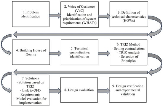
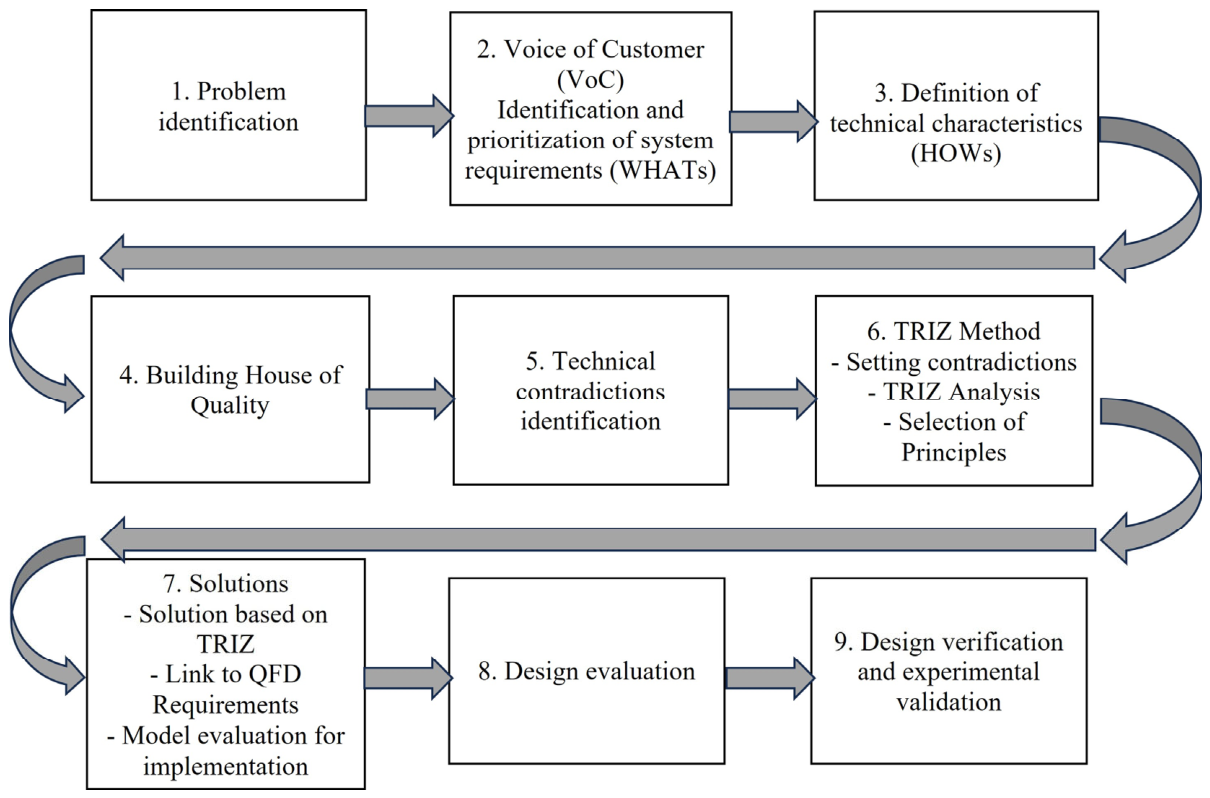
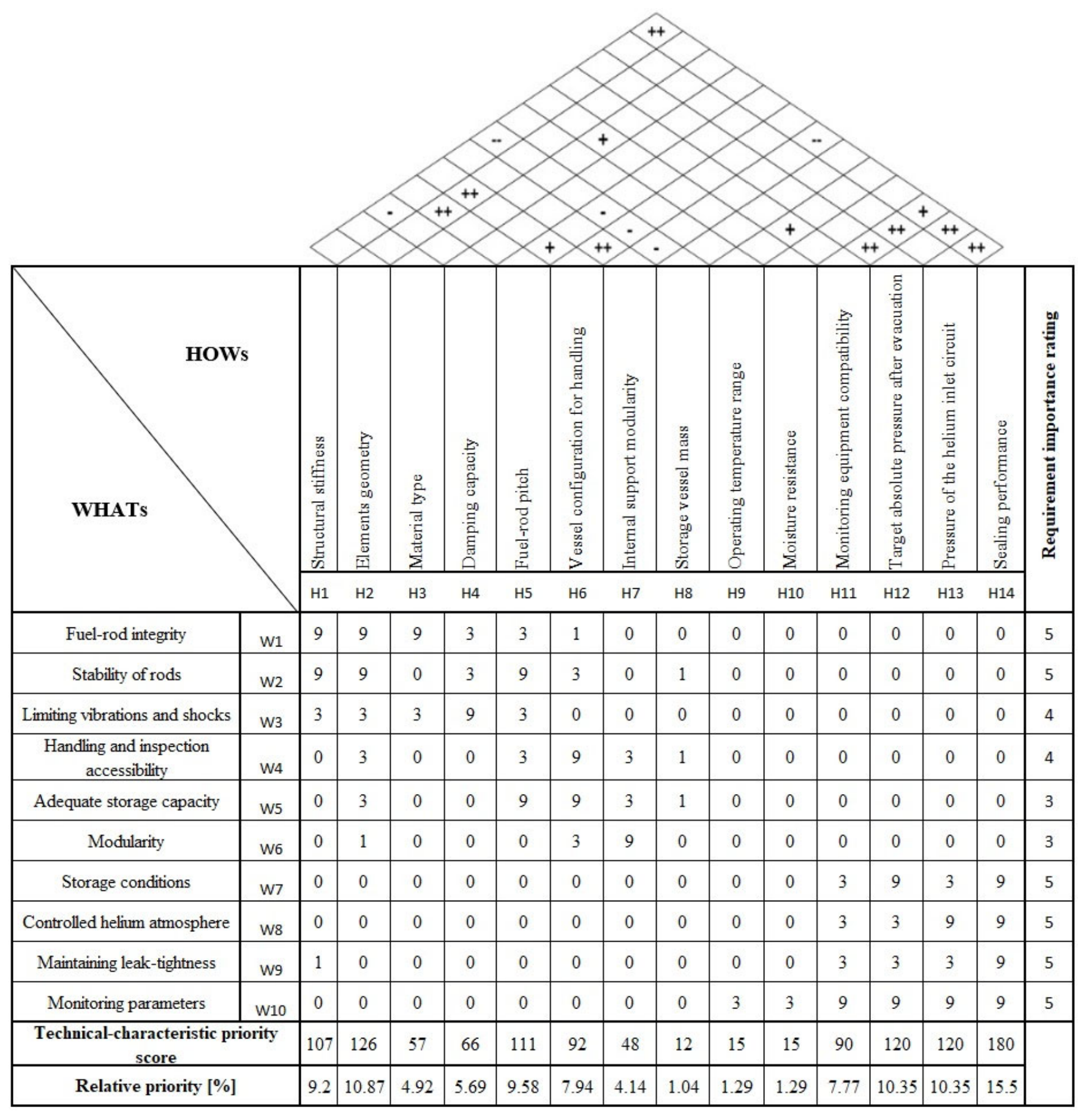
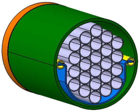
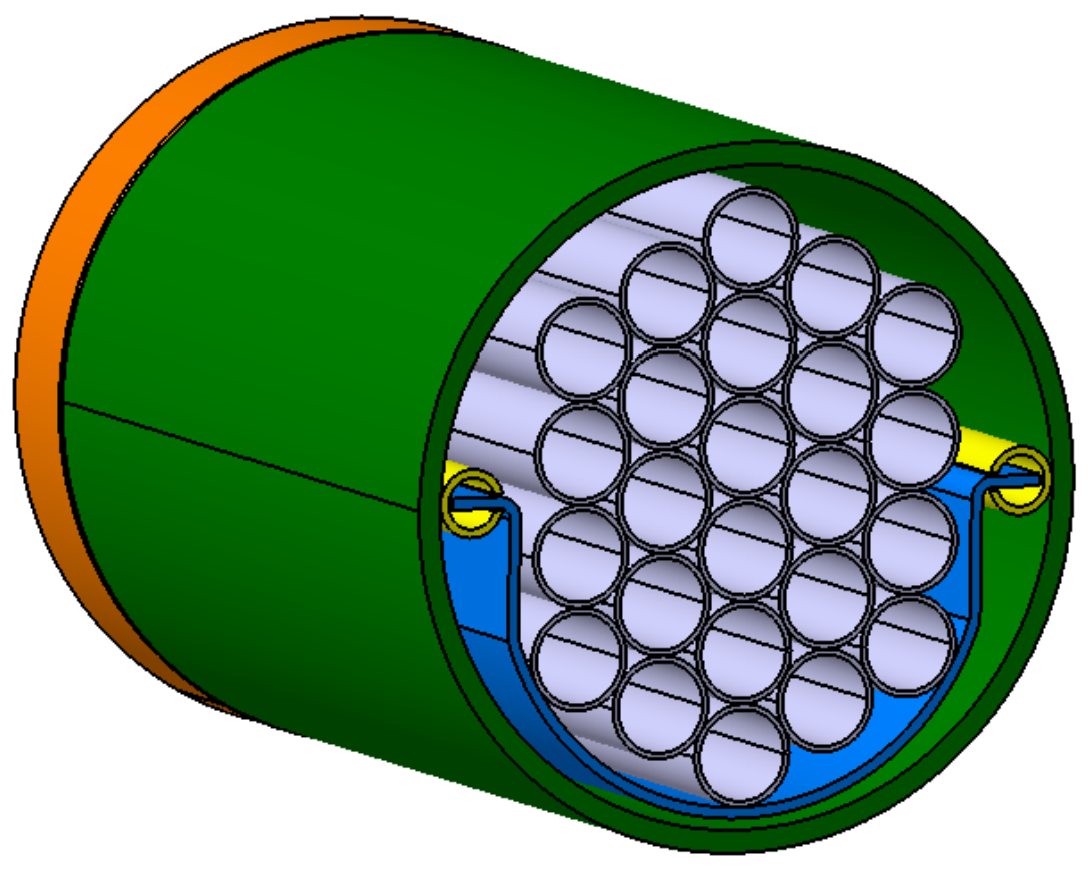
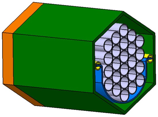
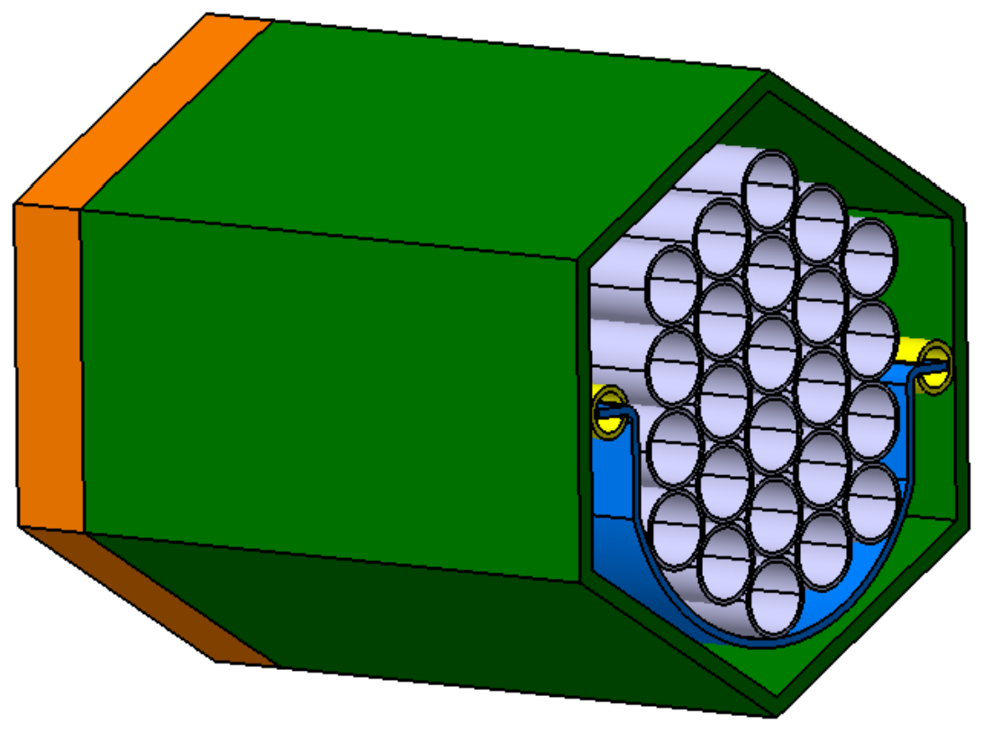
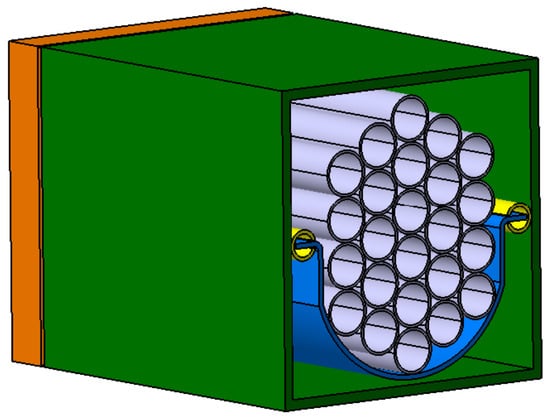
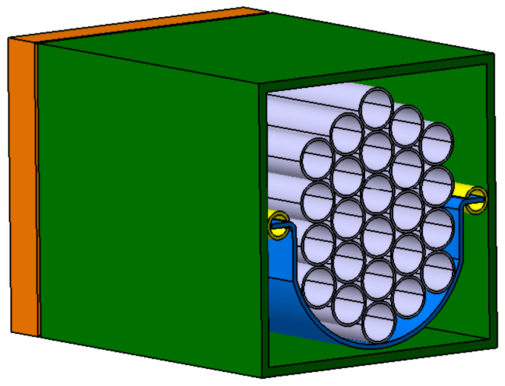
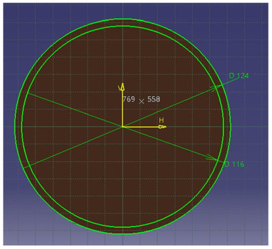
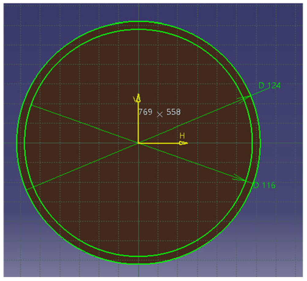
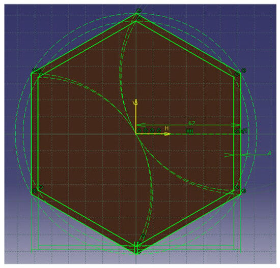
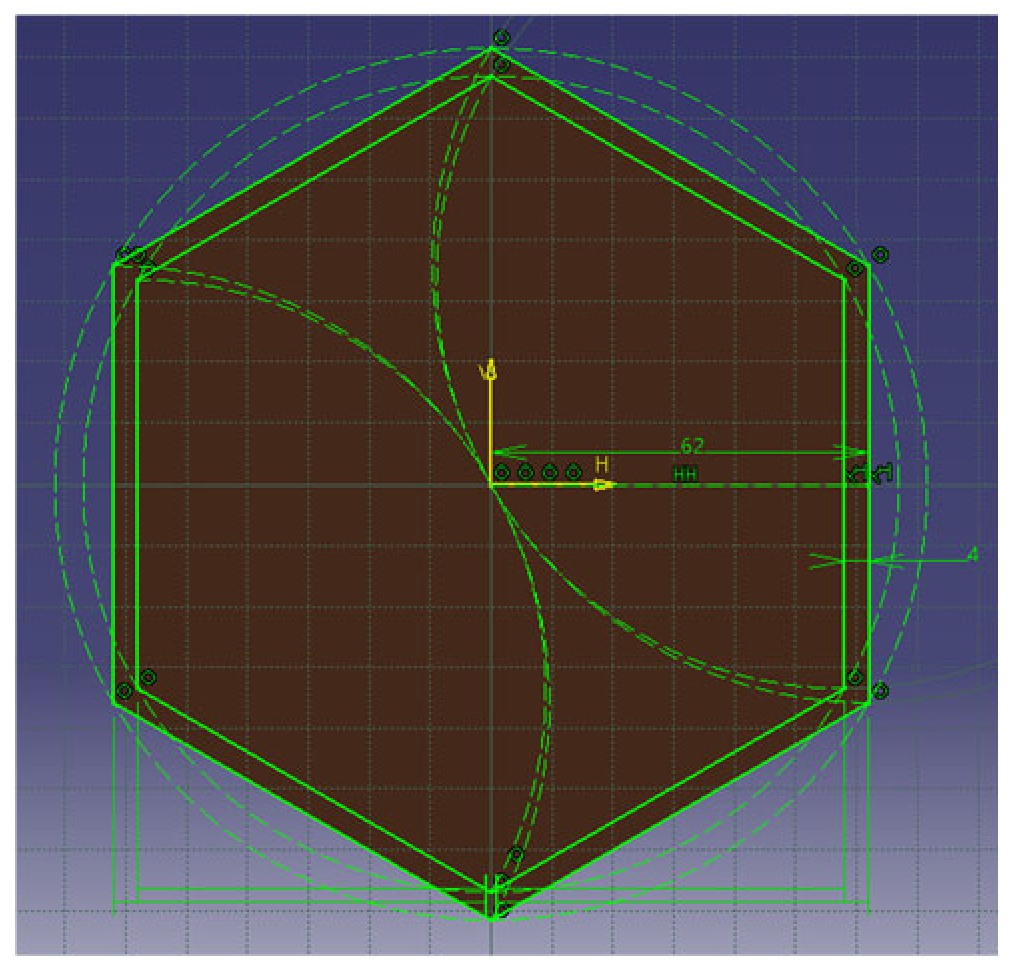
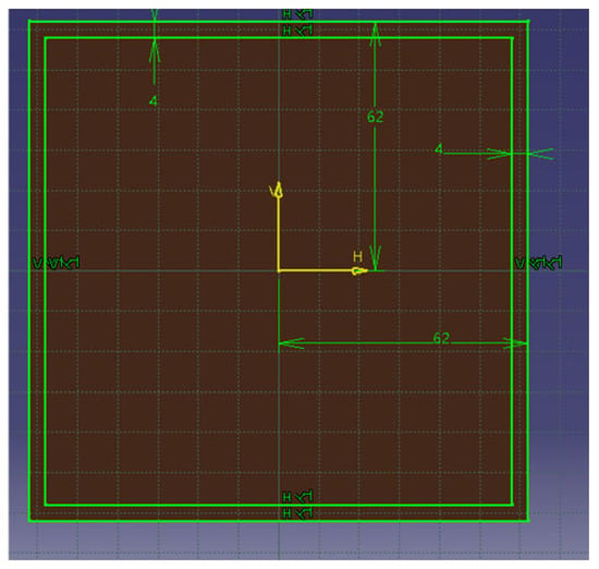
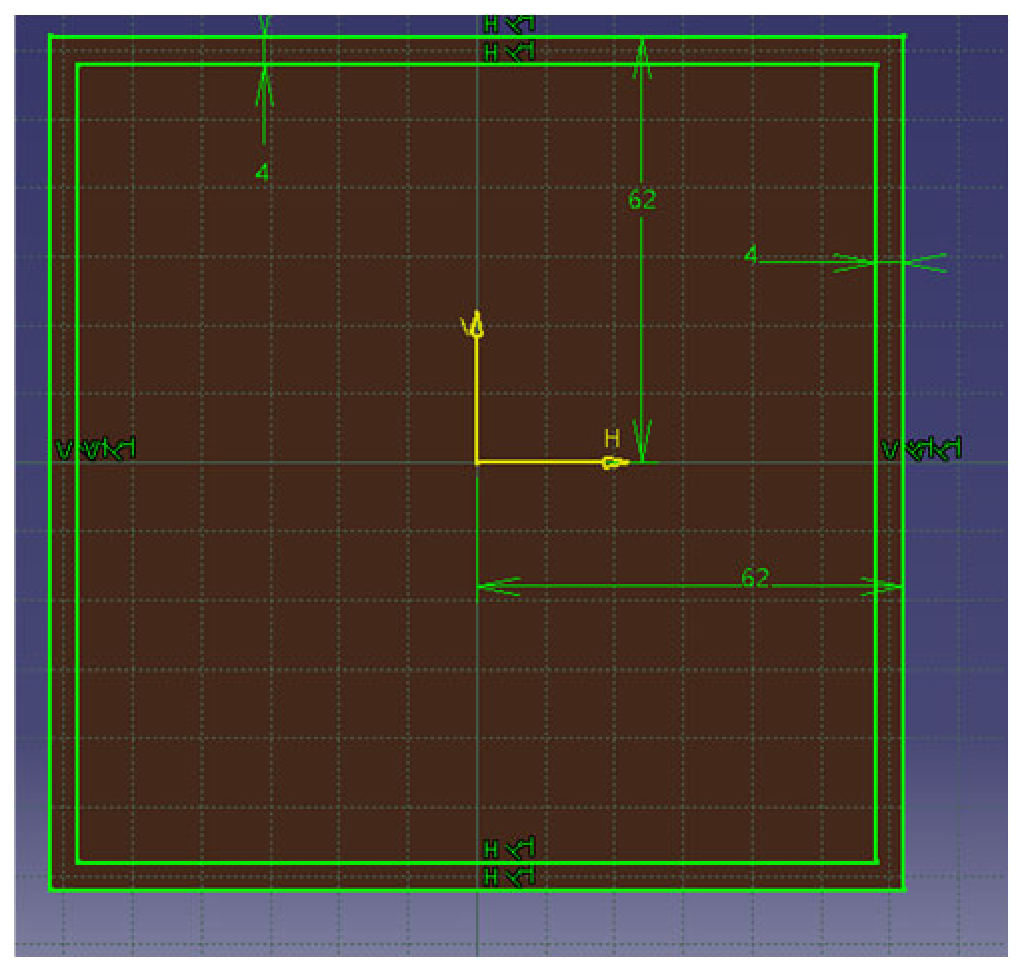
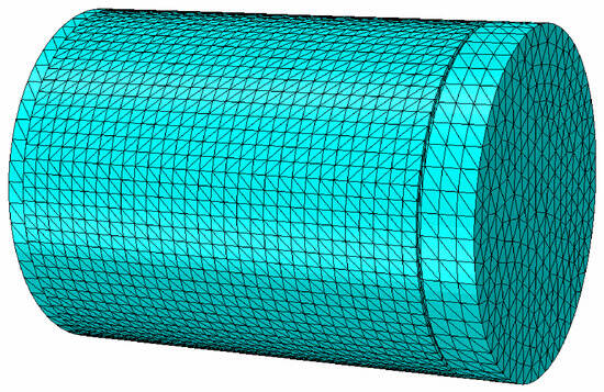
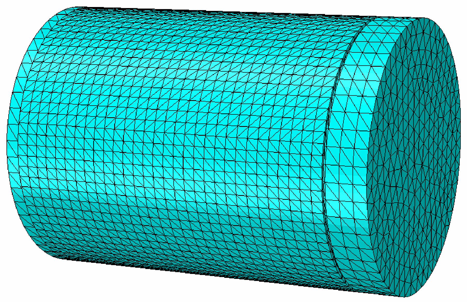
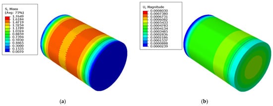
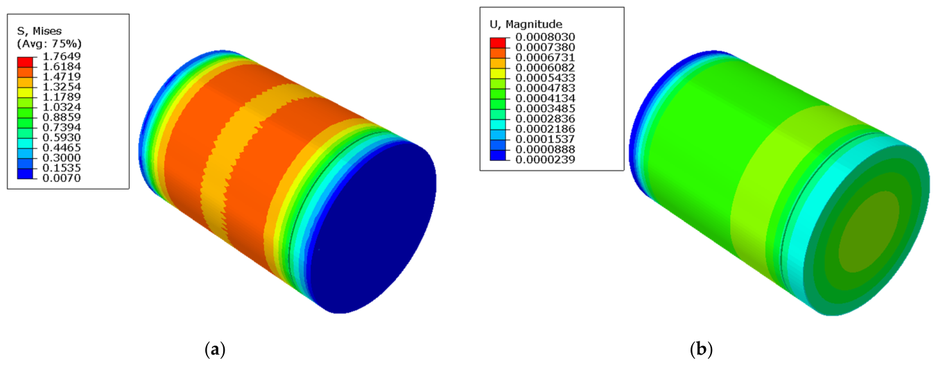
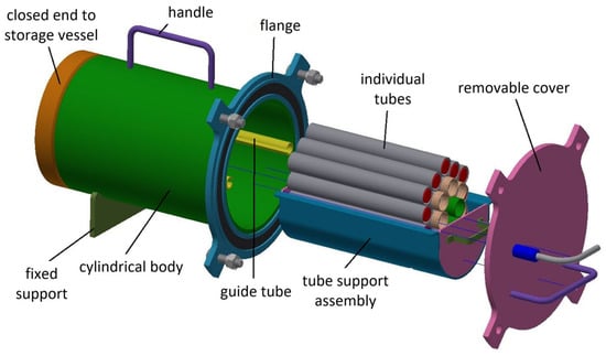
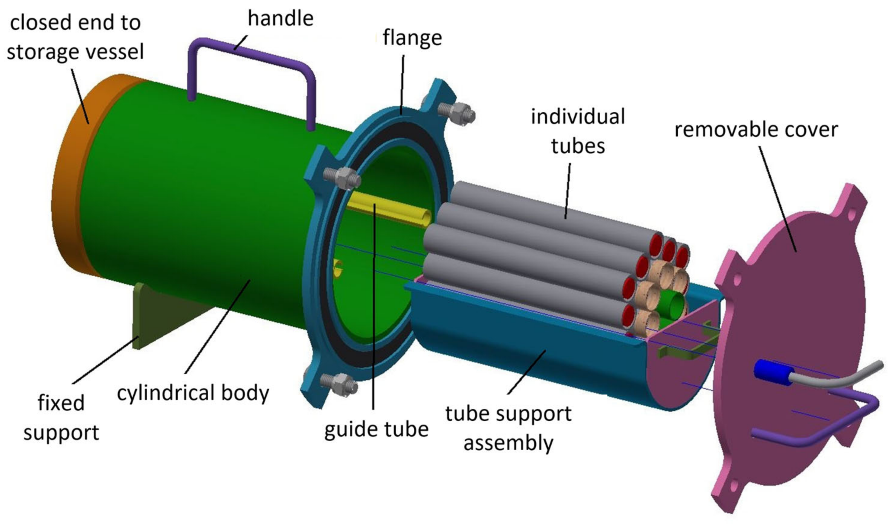

Disclaimer/Publisher’s Note: The statements, opinions and data contained in all publications are solely those of the individual author(s) and contributor(s) and not of MDPI and/or the editor(s). MDPI and/or the editor(s) disclaim responsibility for any injury to people or property resulting from any ideas, methods, instructions or products referred to in the content. |
© 2026 by the authors. Licensee MDPI, Basel, Switzerland. This article is an open access article distributed under the terms and conditions of the Creative Commons Attribution (CC BY) license.