


Abstract
Detonation phenomena in reactive flow systems continue to pose significant challenges for accurate simulation, particularly in 3D validation against experiments and achieving community standardization for schemes. Among the primary difficulties is the selection of suitable convective schemes, which are essential for capturing the complex dynamics of wave propagation and reaction fronts. This study provides a comprehensive historical review of the development and implementation of convective schemes in OpenFOAM, covering the period from 2013 to the present. In addition to documenting the evolution of these methods, we present a detailed technical description of various convective approximation techniques used in detonation simulations within OpenFOAM. This includes an exploration of their underlying principles, advantages, and limitations. Our analysis synthesizes key findings from recent studies and offers practical guidance to researchers when choosing schemes for specific detonation scenarios. It is found that currently, within OpenFOAM, the dominant schemes for convection are the HLLC and KN.
MSC:
76L05
1. Introduction
The existence of a combustion wave and its propagation velocity within a reacting premixed mixture allows for the classification of combustion modes into deflagration or detonation [1]. In the detonation mode, the combustion wave propagates at a supersonic velocity, generating significant jumps in pressure, temperature, and density (e.g., 13–55, 8–21, 1.7–2.6). Once ignited, the combustion wave travels away from the source, transforming the fresh mixture (reactants) into products. The ignition of the reacting mixture is induced by the adiabatic compression of the leading shock that precedes the reaction zone of the detonation wave [2]. This leading shock is typically followed by an induction zone, where the dissociation of the reactants occurs. Several temporal scales are involved in the description of detonations. Notably, the diffusion scales are significantly faster than the chemical or convective scales. Detonation has historically been studied theoretically and experimentally, and, with the increase in computational power, it is now extensively investigated through numerical simulations.
The simplest theory that allows us to determine the stable propagation velocity of a detonation wave is the Chapman–Jouguet (CJ) theory [3]. In the CJ theory, the detonation is modeled as a mathematical discontinuity that propagates steadily. The passage across this discontinuity results in a complex release of the chemical energy stored in the mixture. Crucially, the CJ condition postulates that the flow behind the reaction zone, at the Chapman–Jouguet plane, is sonic relative to the leading shock wave. This criterion selects the unique stable detonation velocity (the CJ velocity) from the range of possible solutions permitted by the conservation equations (Rankine–Hugoniot relationships) and the Hugoniot curve. To address the limitations of the CJ theory, which neglects the internal wave structure that follows the main shock front, Zeldovich, von Neumann, and Döring developed a model widely known as the ZND model [4,5,6].
The ZND model differentiates between the induction and reaction zones that exist between the shock front and the CJ plane. This model facilitates the determination of the structure of planar detonation waves. The significant pressure rise across the shock front induces a corresponding increase in temperature. The time interval between shock compression and the ignition of the mixture is referred to as the ignition delay. Following this, high-speed combustion is initiated, and the mixture reaches chemical equilibrium.
The distinct time scales of the hydrodynamic front and chemical reactions, encapsulated in the ignition delay, result in the spatial separation of the leading supersonic front and the onset of the combustion zone. Although the ZND model provides valuable insight into the structure of detonations, its fundamental limitation lies in the steady-state assumption. In contrast, real gaseous detonations are unsteady, multidimensional, and exhibit significant instability with cellular structures [7,8,9]. Therefore, detonations are inherently three-dimensional phenomena. Nevertheless, classical models such as ZND offer crucial insights into the hydrodynamic–chemical coupling.
The study of detonations has been approached through theoretical [3,10,11,12], experimental [10,13,14,15,16,17,18,19], and numerical methods [20,21,22,23,24,25], each offering distinct advantages and inherent limitations. As mentioned earlier, theoretical models serve as valuable tools for exploring the fundamental principles of detonations without the cost and danger associated with experiments. However, these models are highly simplified and cannot fully capture the complex interactions involved in detonation phenomena.
Experimental investigations, while essential for validating theories and understanding real-world behavior, come with significant drawbacks, including safety hazards, high costs, measurement challenges, complexities in data interpretation, limited accessibility and control, and environmental concerns.
Numerical simulations have become increasingly popular for studying detonations and their interactions. They eliminate safety risks entirely, and the scope of the study is constrained primarily by the chosen model and its associated computational cost. Traditionally, these simulations have been carried out using in-house codes. Numerous studies have applied a variety of models and techniques over time. Early work on detonations dates back to the 1960s and 1970s, when Los Alamos National Laboratory developed the SIN, 2DL, 2DE, and 3DE codes to simulate detonations in condensed-phase explosives [26]. These codes solved the reactive Euler equations, which govern the conservation of mass, momentum, and energy, while incorporating reaction rate models. This work marked a significant transition from simplified, steady-state detonation models to multidimensional, time-dependent numerical simulations. A wide range of solvers have been developed to simulate detonative processes, employing different levels of approximation and a variety of numerical techniques [21,23,27,28,29,30,31,32,33,34].
Combustion science involves intricate interactions and deep coupling among several fundamental disciplines, including thermodynamics, chemical kinetics, fluid mechanics, heat and mass transfer, turbulence, transport phenomena, numerical methods, instrumentation, and diagnostic techniques [35]. The development of computational codes for simulating detonation-like phenomena involves varying requirements depending on model complexity. As the model becomes more ambitious—incorporating more coupled physical phenomena—the development becomes increasingly demanding, and computational costs increase sharply. The OpenFOAM (OF) library [36] provides an open-source framework for studying various physical phenomena, and several detonation studies have been conducted using it. OpenFOAM offers many attractive features, including a complete computational structure for the finite-volume method, thermophysical libraries, multiple spatial and temporal schemes, chemistry solvers, and most notably, the capability to develop custom solvers for specific purposes.
When developing computational code for high-speed reactive flows, it is good practice to first test the coupling between convection and time. Once this is validated, the next step is to introduce chemical effects by modifying the energy equation, adding species transport equations, and incorporating a chemical kinetic model. Furthermore, the convection–reaction coupling itself provides an excellent foundation for studying detonations. If the goal is to investigate viscous effects and the deflagration-to-detonation transition (DDT), diffusion effects and even turbulence must also be considered.
The main objective of this work is to provide a concise review of the developments in convection treatment focused on studying detonation-like phenomena using OpenFOAM technology. The treatment of convective terms in high-speed flow simulations is critical, as it requires a balance between shock-capturing capability and numerical stability. The discretization of convective terms plays a crucial role in determining whether a simulation can accurately capture sharp gradients in the flow field and interactions within boundary layers. If insufficient attention is given to convection, simulations may suffer from spurious oscillations (Gibbs phenomenon), undesired artificial diffusion, or even catastrophic instability.
The treatment of convection in high-speed flows is a complex problem. Supersonic flows exhibit numerical stiffness due to the governing equations admitting discontinuous solutions, such as shock waves, and involving a wide range of characteristic wave speeds. Classical upwind schemes address this challenge by providing both accurate and stable solutions. The upwinding concept is based on incorporating physical properties of the flow equations into the discretization schemes. Upwinding has led to the development of various families of approaches, including flux-difference splitting (also known as fluctuation splitting) [37,38,39,40,41], central-upwind schemes [42,43], flux-vector splitting techniques [44,45] and hybrid schemes [46].
Originally, OpenFOAM was developed with pressure-based algorithms designed to handle incompressible flows. However, the work of Greenshields et al. [47] paved the way for future developments in the study of compressible high-speed flows using OpenFOAM [48,49,50,51,52].
The use of OpenFOAM technology on detonations simulations has increased sharply over the last decade, since the first study by Heidari in 2012 [53]. During the period from 2011 to 2025, more than 100 works were published. Today, OpenFOAM has become a reliable tool for investigating compressible high-speed flows in both industry and academia. Its open-source architecture, along with robust solvers for the Euler and Navier–Stokes equations, allows for the precise simulation of phenomena such as shock waves, expansions, boundary-layer interactions, and detonation-related phenomena in supersonic and hypersonic regimes. Over time, several alternatives have been explored within OpenFOAM, including central-upwind schemes [54,55,56,57,58,59], Riemann problem-based schemes (flux-difference splitting) [60,61,62,63,64,65,66], and flux-vector splitting schemes such as the Advection Upstream Splitting Methods (AUSM) [67,68,69,70,71].
Following the introduction, this work begins with a historical review of detonation simulations using OpenFOAM, highlighting studies that introduced innovations in convection treatment. The next section provides a concise description of the reactive Navier–Stokes equations. Subsequent sections explain the importance of convection in detonation simulations and provide a detailed review of the most commonly used convective schemes in OpenFOAM. Finally, conclusions and recommendations based on the analysis are presented.
2. Key Milestones in Historical Development
After reviewing relevant academic databases such as Scopus, ScienceDirect, Google Scholar, and Web of Science, it is evident that the number of works applying OpenFOAM to detonation-related phenomena is substantial, exceeding 100 publications by December 2025. Consequently, reviewing each individual work would be impractical. Therefore, we classify these studies into two main categories: solver development and applications. This study focuses primarily on solver development, while also incorporating relevant discussions on applications. We briefly describe the pioneering works that introduced a novel numerical scheme to address convection in detonation simulations.
To the best of the authors’ knowledge, the first work on simulating detonations with OpenFOAM was conducted by Ali Heidari in 2012, in his thesis entitled “Numerical simulation of deflagration to detonation transition in hydrogen explosion” [53,72]. In this work, Heidari focused on the numerical simulation of the deflagration-to-detonation transition (DDT) in hydrogen–air mixtures. Two solvers were developed: DetoFoam and DDTFoam. The former solves the Euler equations with a single-step Arrhenius reaction, while the latter solves the compressible, multidimensional Navier–Stokes equations coupled with chemical reactions, enabling the simulation of the entire process from the initial laminar flame, through its acceleration, to the subsequent transition to detonation in a two-dimensional channel. According to Heidari, the solvers achieve steady-state solutions using the Semi-Implicit Method for Pressure-Linked Equations (SIMPLE) algorithm [73] and employ the Pressure-Implicit with Splitting of Operators (PISO) algorithm [74] for transient simulations. Some results are indicated in Table 1.
Table 1.
Comparison of Heidari’s numerical simulation results with experimental and CJ theory values for stoichiometric hydrogen–air mixture (data adapted from [53]).
In 2013, Ettner presented his thesis [60], followed by a published work in 2014 [61]. In these studies, Ettner investigated the deflagration-to-detonation transition (DDT) using OpenFOAM technology based on the formulation of a reaction progress variable. The Ettner solver (ddtFoam) employs the Pressure Implicit with Splitting of Operators (PISO) algorithm—a pressure-based method—to handle the deflagration phase, and a second-order scheme based on the Harten–Lax–van Leer–Contact Riemann solver (HLLC) to compute the detonative processes. The solver is capable of simulating the transition process and enables simulations on relatively coarse grids without resolving all microscopic flow details, thereby allowing engineering-scale modeling. Material properties for the hydrogen–air reactive mixture are obtained from the Chemkin database, and molecular transport coefficients are calculated using Sutherland’s correlation.
In 2016, Gutiérrez Marcantoni presented his PhD thesis on the development of an OpenFOAM solver, rhoCentralRfFoam, for simulating detonation processes using a central-upwind scheme [54]. That solver employs the second-order Kurganov–Noelle–Petrova (KNP) scheme [43], which avoids both characteristic decomposition and direct Riemann problem solution, thereby reducing computational cost while maintaining accuracy. Although the solver does not include diffusive effects, it allows for detailed finite-rate chemistry modeling. The solver was subsequently validated for one- and two-dimensional configurations in two papers published in 2017 [55,56], employing the explicit Euler scheme for time advancement. These works contributed meaningfully to the numerical simulation of detonations in OpenFOAM by developing and validating the rhoCentralRfFoam solver, which integrates high-resolution KNP central schemes with detailed chemical kinetics. The solver demonstrates accurate prediction of detonation velocities and structures in multi-species reactive flows and effectively captures transient phenomena such as detonation initiation and propagation in hydrogen mixtures. By addressing key computational challenges—including mesh resolution, chemical reaction coupling, and shock capturing—within an open-source framework, that study enhanced the capabilities and reliability of OpenFOAM for modeling complex, chemically reactive, high-speed flows relevant to practical detonation applications.
Additionally, in 2016, Vonk presented two foundational works [75] that laid the groundwork for the blastFoam solver, which was formally introduced in 2019.
In 2017, using the AUSM+ [76] Bhattrai and Tang [67] introduced a dual-angle ramp geometry to stabilize near-Chapman–Jouguet (CJ) oblique detonation waves (ODWs) in hypersonic propulsion, specifically targeting compact scramjet combustors. An initial overdriven ramp section (e.g., 15°) generated a strong induction oblique shock wave (OSW) to minimize induction delay, followed by deflection to the CJ angle (∼12.1°), where a near-CJ ODW formed via expansion fan interaction with the weakened OSW.
In 2019, Dinh, Yoshida, and Ishikura [77] presented a numerical framework developed at the Explosion Research Institute Inc. for the simulation of rotating detonation engines (RDEs). The study addressed key challenges associated with modeling the deflagration-to-detonation transition (DDT) within annular combustion chambers. The code incorporated adaptive mesh refinement (AMR) together with a hybrid numerical strategy that combined the PISO algorithm for low-Mach-number deflagration phases with the Kurganov–Tadmor (KT) central-upwind scheme for resolving high-speed detonation waves. A major contribution of that work was the first successful application of a hybrid PISO–KT scheme with AMR for RDE simulations, thereby eliminating the need for manual switching between deflagration- and detonation-specific solvers. Validation against experimental DDT in an obstacle-laden tube demonstrated excellent agreement (see Figure 2 from [77]). The simulated detonation velocity closely matched experimental measurements, and the solver captured the characteristic flame-acceleration profile leading to DDT at approximately . Computational efficiency was achieved through AMR, which significantly reduced the grid size compared to uniform refinement throughout the domain.
As mentioned earlier, in 2016 Vonk and collaborators took the first steps towards the development of the blastFoam solver (Synthetik-2019) [78], a solver designed for simulating highly compressible, multiphase flows with applications in detonation, explosive safety, and air-blast phenomena. They implemented a wide range of options for convection schemes, including HLL, HLLC, AUSM+, and KT. Additionally, several time-stepping methods were incorporated: Euler, second-order and fourth-order Runge–Kutta (RK2/RK4), and second-order, third-order, and fourth-order strong stability-preserving Runge–Kutta (RKX-SPP). The solver also included adaptive mesh capabilities and various options for equation-of-state selection: ideal gas, van der Waals, Tait, stiffened gas (Noble–Abel) [79], Jones–Wilkins–Lee [10], and Cochran–Chan [80].
Instead of providing an exhaustive review of all detonation studies using OpenFOAM, this work focuses primarily on evaluating the numerical schemes employed for convection treatment within the software. Consequently, only the most significant developments in this area are discussed. Nevertheless, Appendix A provides a comprehensive overview of recent publications organized into summary tables, with Table A1 detailing the contributions from 2020.
Although several relevant physical findings were reported in 2020, as summarized in Table A1, the treatment of convection in 2020 did not incorporate any innovative approaches.
In 2021, the most significant numerical developments in convection treatment were the works of Xia [81] and Tang [34]. Xia developed the solver BYRFoam and incorporated the capability to use different schemes for convection treatment:
- KT (Kurganov and Tadmor) and KNP.
- Harten–Lax–van Leer Riemann solver (HLL).
- Harten–Lax–van Leer contact (HLLC).
- Advection Upstream Splitting Method (AUSM).
Notwithstanding the new implementation, the specific convection scheme used for the pre-detonator simulations is not explicitly stated. The paper focuses on the solver’s compatibility with multiple schemes rather than specifying which one was selected for the presented results.
From 2022, both the works of Jiang et al. and Adhikari et al. implement the AUSM+-Up scheme for convection. Jiang et al. [68] present a robust, well-implemented, and carefully validated detonation solver with a solid methodology (second-order AUSM+-Up and RK4), which could be further enhanced by more rigorous error analysis, realistic transport modeling, and 3D validation. In contrast, although Adhikari et al. implement the same convection scheme, they introduce modifications to the face flux reconstruction and adopt an AUSM+-Up-based approach for species convective fluxes, bypassing the need for OpenFOAM modules [69].
From 2023, the implementations by Sun [82], Weng and Mével [83], and Wang [84] are highlighted because they introduce two schemes that were not previously used in detonation simulations with OpenFOAM: HLLC-P and HLLC-LM [41], respectively.
Despite these innovations, Weng and Mével employed the HLLC scheme in their simulations using the blastFoam framework, which incorporates efficient chemistry and real-gas models from Cantera. The validation of the new solver was successfully carried out by comparing the results with appropriately selected benchmark problems, such as the Sod problem, oblique shock, constant-volume reactor, steady detonation speed, 1D detonation flow structure, and 2D cellular structure.
Sun and collaborators were the only ones to implement the HLLC-P scheme (HLLC with the pressure-control technique [40]). They also provided a thorough validation of detonationFoam, accurately capturing the propagation of the shock wave and the contact discontinuity, with their predictions of the cellular structure showing good agreement with reference results.
In 2024, the implementation of the AUSM+M scheme by Cheng et al. [85] was particularly noteworthy. Cheng et al. developed the BYCFoam solver specifically for simulating rotating detonation engines.
The solver includes optimized reconstruction variables and multiple flux schemes, integration of the Cantera library for detailed chemistry and accurate transport properties, and implementation of adaptive mesh refinement (AMR) with dynamic load balancing for computational efficiency. Comprehensive validation tests—including shock-tube problems, homogeneous ignition, premixed flames, planar detonations, detonation cellular structures, and rotating detonation combustors—demonstrate BYCFoam’s ability to accurately simulate both deflagration and detonation processes. Errors are typically below 1% compared to theoretical predictions, making it a valuable tool for RDE research.
Some selected works from 2025 are presented in Table A6 of Appendix A. The development of shockFluidX by Wang and Zhang stands out because, although it introduces no innovations in the convection scheme and does not explicitly focus on detonations, the implementation itself is highly innovative.
The novel modular compressible flow solver, built on OpenFOAM v12 for high-speed aerodynamic applications, addresses critical limitations in existing open-source CFD tools through four key innovations.
The solver shockFluidX leverages the modular architecture introduced in OpenFOAM v11. This new development includes the integration of the PIMPLE algorithm in an efficient manner, achieving stability comparable to Runge–Kutta temporal schemes. It also provides runtime selection (RTS) capability for convective flux selection, along with new high-resolution total variation diminishing flux limiters (SSFL [86], gva, sgvl, sgprk [87], and the ROUND family [88,89]).
Additionally, the implementation features a generalization of the three-dimensional automatic mesh refinement (AMR) with dynamic load balancing (DLB), improving accuracy and reducing computational cost. The authors also provide an exhaustive verification and validation procedure using classical benchmarks and practical aerospace applications. However, it may be disappointing for the OpenFOAM community that shockFluidX is not yet open source.
This section presented a brief review of relevant studies conducted between 2012 and 2025 that utilized OpenFOAM to simulate detonation processes and introduce novel convective schemes. The reviewed literature highlights key milestones, demonstrating the growing adoption of OpenFOAM for high-speed reactive flow simulations. Figure 1 illustrates the timeline of works from 2012 to 2025 that successfully implemented new numerical schemes within the OpenFOAM framework.
Figure 1.
Timeline of the evolution of convection scheme implementations in OpenFOAM for detonations simulations [53,54,60,67,68,77,81,82,83,84,85].
3. Governing Equations
The simulation of detonative processes requires solving a coupled system of transport equations, the complexity of which depends on the desired level of physical fidelity for the problem under consideration. For generality, the problem can be expressed in terms of the reactive Navier–Stokes equations:
where is the vector of conserved variables and is given by:
The convective and diffusive flux vectors are respectively
and finally the source term vector:
As discussed in subsequent sections, each of the aforementioned terms—convective, diffusive, and source—must be accurately approximated to obtain a reliable solution for the problem at hand. The specific evaluation of these terms depends on the numerical method employed. Within the OpenFOAM framework, the finite-volume method with support for polyhedral cells is used. The following section provides a discussion of the various approaches that have been implemented in OpenFOAM to address different types of reactive flow problems. The presented system of transport equations (see Equations (1)–(4)) requires an equation of state in the form to link the state variables, the constitutive equations for viscous, heat, and species diffusion fluxes, as well as a kinetic model to compute species production/consumption and the heat released by combustion.
4. Importance of Convection Treatment on Detonation Simulation
In simulations of detonations, the significance of convection treatment cannot be attributed to a single factor when using shock-capturing methods (SCMs). In supersonic flows, it is well established that transport mechanisms are not governed solely by the bulk motion of the fluid. Instead, wave-induced transport phenomena play a fundamental and often dominant role in the overall transfer of mass, momentum, and energy. The SCM approach seeks to represent the movement of the front, which is physically much thinner than the computational cell used. The actual thickness of a gaseous detonation is approximately ∼1 ; however, the spatial discretization is several orders of magnitude larger. This scale disparity must be carefully considered when designing the schemes [90]. Extending methods developed for slow flows is challenging, as using a pressure equation requires the introduction of artificial viscosity to maintain stability, which may not be appropriate.
The primary ignition mechanism in detonation processes is the adiabatic compression of the mixture by the shock front. The intense gradients across the shock are responsible for initiating self-sustained combustion in the mixture. Detonation fronts are inherently spatially unstable [2], exhibiting discontinuities caused by transverse shocks that propagate obliquely across the front, creating shock–shock interactions (Mach stems). It has long been recognized that accurate representation of triple points is critical for technical and safety analyses [23,91,92,93].
These interactions form triple-point configurations, resembling fish scales, which are identified as cellular structures (see Figure 2).
Figure 2.
Typical detonation at different instants in time. Points A, B, C, and D denote the ‘fish-scale’ pattern of the cellular, diamond-shaped tracks left by the triple-point intersections of shock waves. (adapted from [2]).
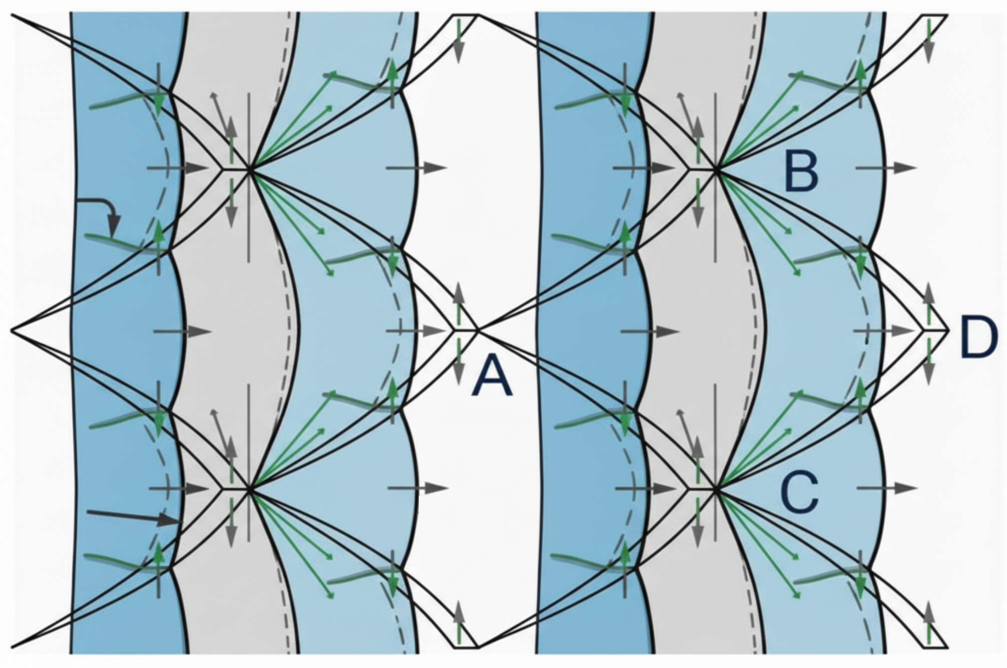
Figure 3 illustrates the typical detonation structure at four different instants along the triple-point trajectory. To accurately represent all involved discontinuities (i.e., slip lines and shocks) and their interactions, the convection scheme plays a critical role. Therefore, its impact on the correct computation of dynamic detonation parameters [94,95]—as well as its ability to capture waves precisely without introducing spurious oscillations or numerical instabilities—is crucial.
Figure 3.
Typical cellular two-dimensional unstable detonation at different instants in time (adapted from [96]).
5. Solutions Algorithms
As mentioned previously, combustible mixtures can support two distinct modes of combustion. The first, known as deflagration or the slow mode, occurs when the flame propagates at velocities of approximately relative to the unburned gases, resulting in negligible overpressure. At the other extreme is detonation, where the reaction wave propagates at speeds of around , accompanied by a significant and rapid rise in overpressure across the wave. In both deflagration and detonation scenarios, chemical kinetics play a crucial role in shaping the combustion characteristics. However, from a fluid dynamics perspective, each regime exhibits distinct features. Deflagration is characterized by subsonic flame propagation and relatively smooth pressure increases, influenced by turbulence and confinement. In contrast, detonation involves a supersonic shock wave, accompanied by an almost instantaneous and dramatic rise in overpressure. Therefore, a solver for detonation or deflagration-to-detonation transition (DDT) simulations must incorporate several key components. While the fundamental features of detonation can be captured by solving the reactive Euler equations, accurately modeling the DDT phenomenon requires accounting for viscosity and turbulence effects, which significantly influence the transition dynamics and flame behavior. Consequently, a numerical algorithm must address several critical aspects to simulate detonation and DDT phenomena accurately:
- Time advancement schemes to ensure both numerical stability and accuracy in dynamic simulations.
- Treatment of convective terms to accurately capture the propagation of shock waves and flames.
- Modeling of molecular and turbulent diffusion processes to simulate species transport and heat diffusion.
- Interaction between chemical kinetics and turbulence, capturing the coupling between combustion processes and turbulent flow dynamics.
In the following section, we discuss each of the key aspects relevant to the convection treatment mentioned above, with a focus on the finite-volume framework provided by OpenFOAM. The Navier–Stokes equations are presented in their integral form as follows:
Each term in the integrated system of equations must be approximated consistently. In the following sections, we discuss the approaches used in OpenFOAM for approximating convection terms.
5.1. Convective Terms
As highlighted before, when solving the Euler or Navier–Stokes equations for high-speed flows, it is crucial to treat the convective terms appropriately in order to ensure stability, accuracy, and boundedness, while avoiding non-physical oscillations. The concept of upwinding plays a fundamental role in any numerical method designed for such flows. A comprehensive review of this concept can be found in the influential paper by van Leer [97,98]. Upwinding involves considering the physical direction of wave propagation [99,100], which is essential for accurately capturing sharp gradients such as shock waves and preventing numerical instabilities or excessive dissipation.
Methods for solving supersonic flows are typically categorized into flux-difference splitting (FDS) [37,38,101], flux-vector splitting (FVS) [44,45,76] and central-upwind schemes (CUSs) [42,43]. These approaches are density-based, meaning they treat density as a primitive variable, which is directly obtained from mass conservation. In contrast, pressure-based methods, originally developed for incompressible flows, were designed to handle the coupling between pressure and velocity. The precursor to these methods was the Semi-Implicit Method for Pressure-Linked Equations (SIMPLE), developed by Spalding and Patankar [73,102].
Any convective term is discretized as follows:
where represents the intensive property being transported according to the respective principle, multiplied by the density . For example, in the momentum transport equation, the transported property is linear momentum, which can be expressed in terms of the momentum per unit mass . Therefore, for momentum conservation, we have .
The discretization process is completed when the surface integral is evaluated using an appropriate Gauss quadrature on all the faces of the computational cell, with the quadrature points denoted as :
In OpenFOAM, the midpoint rule is used for integration. Thus, the weight is , and any convective term is evaluated as:
The convective flux at each face is given by , where and are the velocity and the transported property at the face, respectively. To compute these values, it is necessary to approximate them using the nodal values. The challenge lies in computing and through an appropriate interpolation or reconstruction method within the framework of the finite-volume method. One of the simplest ways to obtain the face values is through the linear interpolation scheme [103]. However, linear convection schemes are prone to producing oscillations, as they lack inherent numerical dissipation. This absence of numerical diffusion allows spurious oscillations to develop near sharp gradients or discontinuities in the solution, such as shock waves. These oscillations occur because the discretization method does not sufficiently dampen high-frequency numerical errors, leading to non-physical undershoots and overshoots around discontinuities.
To mitigate such oscillatory behavior, several techniques have been developed. One of the simplest methods that avoids oscillations is the upwind scheme; however, it suffers from excessive numerical diffusion [100,104,105]. The following sections provide a concise review of the theoretical foundations underlying various numerical frameworks implemented in OpenFOAM for detonation modeling. These include density-based formulations, such as flux-difference splitting (FDS) (notably the HLLC family) and flux-vector splitting (FVS) (including the AUSM family), as well as central-upwind approaches like the Kurganov–Noelle–Petrova (KNP) scheme. Furthermore, pressure-based and hybrid methodologies are discussed in the context of high-speed reactive flows. Based on the data synthesized in Section 2 and Appendix A, Figure 4 illustrates the distribution of these approaches across the literature. Notably, central-upwind techniques (KNP and KT) and FDS schemes (HLLC family) emerge as the predominant methodologies in the field.
Figure 4.
Usage percentages of schemes in OpenFOAM for detonation simulations.
5.1.1. Density-Based Approach
At the beginning of this section, we highlight that for supersonic flows, methods classified as FDS and FVS were historically used. These methods are grouped as density-based because density is solved directly from the mass conservation equation. Additionally, FDS, FVS, and hybrid methods can be characterized as conservative, upwind, finite-volume, shock-capturing schemes.
Before proceeding, the following nomenclature is introduced. In OpenFOAM, discretization is performed in terms of owner (P) and neighbor (N) cells. To simplify the notation, the owner cell is denoted by index i; thus, in a simple 1D configuration, the neighbor cell has index , and the cell to the left of the owner has index . Then, the interface between owner cell and neighbor cell is denoted as (See Figure 5).
Figure 5.
Discretization nomenclature.
Traditionally, FDS schemes were classified as Godunov-type schemes because they involve the direct solution of the Riemann problem to account for wave interactions between left and right states. The FVS methods exploit the homogeneous property of the flux vector to decompose it into components associated with positive and negative eigenvalues. The flux is split as , where contains contributions from waves moving right (positive eigenvalues) and contains contributions from waves moving left (negative eigenvalues).
The classical taxonomy of density-based methods considers the FDS and FVS classification, but it has a shortcoming: central-upwind schemes (CUSs) cannot be properly classified into either category. Central-upwind schemes represent a third approach to handling convective terms in the reactive Euler equations. Central-upwind schemes offer a pragmatic hybrid: they avoid solving Riemann problems entirely (reducing Jacobian overhead) while using estimates of one-sided wave speeds at cell interfaces to minimize numerical dissipation.
Over time, several approaches have been used in OpenFOAM to handle convective terms; the following offers a succinct review of them.
5.1.2. Flux-Difference Splitting
The core idea behind the flux-difference splitting (FDS) family of schemes [37,106,107] (or fluctuation splitting [97]) is decomposing the flux difference between left and right states into characteristic components based on the system’s wave structure:
where is the kth eigenvalue (wave speed), is the kth right eigenvector (wave direction), is the kth wave strength, and m is the number of conservation laws. Therefore, the flux is split by wave speed sign: positive eigenvalues carry information rightward, negative leftward.
In FDS schemes (Godunov-type schemes), the numerical flux is determined by solving the local Riemann problem using data from neighboring cells, i and (in the 1D context). While the Riemann problem is a well-established topic in numerical methods for compressible flows, it is worth briefly recalling the key details for the context of this work. The Riemann problem for the Euler/Navier–Stokes equations is an initial value problem (IVP) defined in the domain , , with initial data:
The schematic representation of the Riemann problem is shown in Figure 6. The problem structure consists of three waves: the middle wave, which is always a contact discontinuity (C), and the left and right waves, which are nonlinear and can either be shocks (S) or rarefactions (R). Consequently, there are four possible wave configurations: SCS, SCR, RCS, and RCR.
Figure 6.
The Riemann problem. Where the superscript * expresses values in the star zone.
Rarefactions involve continuous solutions, whereas contact discontinuities and shocks exhibit discontinuous behavior. The region between the left and right nonlinear waves is characterized by constant pressure p and velocity u and is traditionally referred to as the star regionIn the Riemann problem, the solution does not depend independently on both space and time but rather only on the ratio . The lines along which the solution depends solely on are called the characteristics of the hyperbolic system.
The solution to the Riemann problem, , with data from along the t-axis at , is used to define the intercell numerical flux, , in the first-order Godunov method [106]. Consequently, families of methods such as flux-difference splitting (FDS), flux-vector splitting (FVS), and central schemes (CE) can be considered types of Godunov-type schemes [106]. The primary difference between these methods lies in how they construct numerical fluxes at cell interfaces.
Godunov-type schemes use the exact or approximate solution of the Riemann problem at each cell interface to resolve discontinuities and compute physically consistent, upwind numerical fluxes. However, the exact solution of the Riemann problem requires an iterative procedure, which can be relatively complex and computationally expensive. Therefore, approximate solvers are typically used in practice, especially for reactive flow simulations. This approach treats the discontinuity between adjacent cells as an initial-value problem for hyperbolic PDEs, capturing shock waves, rarefactions, and contact discontinuities in a physically accurate manner [99,100,108,109,110]. These schemes are known for their shock-capturing capabilities. These schemes use limiters designed to render the scheme oscillation-free, leveraging the total variation diminishing (TVD) property [107] to balance high-order accuracy with stability by controlling numerical oscillations near discontinuities, such as shock waves.
- The HLLC solver
The first FDS method used to simulate detonations with OpenFOAM was the HLLC solver (Harten-Lax-van Leer-contact). In particular, the HLLC solver is an evolution of the HLL (Harten–Lax–van Leer) Riemann solver that incorporates the contact wave into the wave pattern. The HLL is a two-wave model (Figure 7a), while the HLLC is a three-wave model (Figure 7b), where the approximate intercell numerical flux is obtained directly [38]. The key elements are the wave configuration and the assumption that the wave speeds are known. Using the integral form of the conservation laws, an approximate closed-form expression for the numerical flux is derived.
Figure 7.
Wave structure of HLL and HLLC approximate Riemann solvers.
The general form of the numerical convective HLLC flux is:
In 2013 and 2014, Ettner presented his PhD thesis titled Effiziente numerische Simulation des Deflagrations-Detonations-Übergangs [60] and the paper “Numerical Simulation of the Deflagration-to-Detonation Transition in Inhomogeneous Mixtures” [61]. In these works, Ettner developed an efficient CFD solver within the OpenFOAM framework to simulate the complete combustion process, including the deflagration-to-detonation transition (DDT) in hydrogen–air mixtures—critical for nuclear safety assessments. A density-based solver using the Harten–Lax–van Leer–Contact (HLLC) Riemann solver was implemented, setting Ettner’s approach apart from traditional pressure-based methods. The HLLC solver, in combination with high-order reconstruction (second order with limiters), accurately captures shock discontinuities while preserving sharp shock profiles without introducing spurious oscillations [38,99]. The scheme’s advancement aligns with the formulation presented in Equation (32), as it is based on Godunov-type methods [106].
Regarding the implementation by Ettner, which is based on the development by Borm [48], the approach proposed by Einfeldt and Davies [110,111] for computing the wave velocities is used. This method is fundamentally based on the eigenvalues obtained from the Roe average [37]:
where denotes the Roe-averaged values of the particle velocity defined as follows:
and the averaged enthalpy:
The parameter d introduced by Einfeldt is [112]:
where is given by:
Finally, and are given by:
with
Details about the influence of wave velocity determination on the HLLC solver can be found in [113].
The scheme used by Ettner employs gradient reconstruction with second-order spatial accuracy, stabilized through multidimensional cell-limited limiters that suppress spurious extrema on cell interfaces while preserving second-order accuracy in smooth regions. This balances accuracy demands (required for resolving flame–shock interaction) with stability constraints (essential for capturing discontinuities without nonphysical oscillations). The test cases demonstrate that applying these limiters eliminates over/undershoots in shock-tube problems while maintaining excellent agreement with analytical solutions for pressure, temperature, and velocity.
The superior shock-capturing ability of the HLLC scheme directly manifests in the quality of the predicted results. In homogeneous mixture simulations , the numerical flame propagation agrees excellently with experiments through the obstacle region and shows physically sensible flame deceleration in the unobstructed zone. More critically, for inhomogeneous mixtures with vertical concentration gradients, the scheme successfully captures two distinct DDT mechanisms:
- Shock–flame interaction via reflected shock impingement leading to precompression and subsequent autoignition.
- Direct autoignition behind Mach stems formed at obstacles.
The HLLC scheme’s accurate shock tracking proves essential for detecting the asymmetric detonation fronts characteristic of stratified mixtures. In the gradient case, the simulation correctly predicts pressure loads reaching ∼120 bar—nearly the homogeneous equivalent—due to Mach reflection on the bottom wall (low content) generating higher post-shock pressures than the top wall (rich ). This remarkable result—extreme pressures in fuel-lean regions—would be missed or severely underestimated with dissipative pressure-based methods.
For the gradient case, the scheme accurately tracks the transition from a fast deflagration (∼1000 m/s) to a Chapman–Jouguet detonation (∼2000 m/s), with the intermediate overdriven state (∼2500 m/s) properly captured. The predicted flame velocity variations exhibit physical consistency with experimental measurements, though quantitative differences in the acceleration phase reflect grid resolution limitations and ignition modeling simplifications.
While the HLLC scheme provides superior shock resolution, results are obtained on relatively coarse grids , which represents the minimum resolution for grid-independent DDT location prediction. This computational economy is preserved through subgrid combustion models (reaction progress variable with Weller turbulent burning speed and tabulated autoignition delay times) that decouple accuracy from grid resolution. The Min-Max model for autoignition adds critical functionality by accounting for shock-induced temperature rise in subgrid volumes, improving accuracy at the DDT threshold without requiring ultrafine discretization.
Ettner’s work demonstrates that HLLC-based schemes, coupled with appropriate time integration (explicit, CFL-constrained) and subgrid turbulence/chemistry models, can effectively simulate the complete DDT process on engineering grids. The scheme successfully captures shock propagation, shock–flame interaction, and the resulting autoignition mechanisms—phenomena fundamentally inaccessible to standard pressure-based approaches. The excellent agreement with shock-tube validation and subsequent experimental comparisons for both homogeneous and inhomogeneous hydrogen–air mixtures validates the numerical approach for safety-relevant applications in complex geometries.
- The HLLC-P solver
The HLLC-P solver introduces a pressure-dissipative term in the numerical flux to damp pressure perturbations and suppress oscillations. This feature improves the scheme’s ability to sharply capture various types of discontinuities
where , , , and are respectively the Mach number, velocity of sound, and velocity components averaged at the interface according to Roe. Evaluating involves the use of the function:
where
It should be emphasized that, as is mentioned in the paper from Xie et al. [40], the correction term is only activated in the vicinity of shocks, and in the smooth region, f approaches unit and the HLLC-P scheme turns into the HLLC solver. The final flux is:
The work of Sun et al. directly addresses and validates the HLLC-P scheme, making it highly relevant for comparative assessment. A direct numerical comparison of the shock-tube problem (Figure 5b from [82]) reveals that, compared to the KNP and standard HLLC schemes, the HLLC-P scheme implemented in detonationFoam exhibits lower dissipation, thus allowing for a more accurate resolution of shock propagation. The paper presents an extensive validation suite across eight test cases, ranging from 0D homogeneous ignition to 2D cellular detonation structures and oblique detonation waves. All tests show excellent agreement with reference data or experimental results, with maximum relative errors typically less than 7% for ignition delay predictions and less than 1.78% for shock-tube pressure. Sun and collaborators demonstrate that the HLLC-P scheme outperforms both the standard HLLC and KNP schemes in shock-capturing tasks, suggesting that this pressure-correction modification significantly improves the resolution of detonation phenomena.
- The HLLC-LM solver
The HLLC-LM solver was introduced by Fleischmann [41]; it is an HLLC-family solver specifically designed to address grid-aligned shock instability. This instability occurs when standard HLLC Riemann solvers are combined with high-order reconstruction methods, causing shock waves aligned with the computational grid to become unstable and thus contaminating the simulation results. This issue is particularly problematic in 3D simulations, where computational costs are already high, making numerical robustness crucial. Fleischmann identified that grid-aligned shock instability arises from an improper scaling of the acoustic and advective contributions to numerical dissipation in the low-Mach-number limit [114]. In the absence of shocks, upwinding becomes unnecessary and in fact introduces excessive numerical dissipation, which contradicts the goal of minimizing it. Therefore, Fleischmann’s objective was to develop an HLLC flux formulation that transitions smoothly to the central flux in the low-Mach-number limit.
Using the jump condition across the left state, the following flux is derived:
From the jump condition of the other side of the Riemann fan, the flux becomes:
Averaging the both last equations:
An equation for is obtained in a similar way:
The nonlinear signal speeds are calculated according to:
with
The velocity component u depends on the Riemann problems at the cell faces. The wave speeds and are used to evaluate the fluxes and . The quantities , , and are computed in terms of and .
Unlike the work of Sun et al., which employed the standard HLLC-P scheme, Wang et al. validated the HLLC-LM variant, which is specifically designed to suppress grid-aligned shock instabilities [84]. This capability is crucial for complex DDT scenarios, where multiple compression waves interact with obstacles and walls. The scheme’s reduced dissipation, compared to other shock-stabilized HLLC variants, preserves fine-scale turbulent structures that are critical for accurately modeling flame–turbulence interactions and deflagration-to-detonation (DDT) mechanisms.
Wang et al.’s use of the HLLC-LM scheme represents a state-of-the-art flux formulation for unsteady detonation-adjacent phenomena. While Sun et al. demonstrated the superiority of HLLC-P over standard HLLC and KNP schemes, the HLLC-LM formulation specifically addresses grid-aligned shock pathologies that arise in 3D and high-order simulations—precisely the regime in which DDT simulations are conducted. The paper validates that HLLC-LM can handle the competing demands of shock stability and low dissipation simultaneously, making it well suited for capturing both sharp detonation fronts and intricate turbulent structures.
Total variation diminishing (TVD) numerical schemes were proposed to handle the convective terms in detonation simulations [107,115,116,117]. These TVD schemes, considered Godunov-type methods [106], are known for their shock-capturing capabilities. Designed to be oscillation-free, flux-limited schemes, TVD methods balance high-order accuracy with stability by controlling numerical oscillations near discontinuities, such as shock waves.
5.1.3. Flux-Vector Splitting
Flux-vector splitting schemes split the flux vector into components based on the sign of their eigenvalues (wave speeds) and then apply upwind differencing to each component separately [45,118]. This approach avoids solving Riemann problems entirely, relying instead on direct characteristic decomposition. Physically, this technique for achieving upwind bias is based on the observation that a fluid is an assemble of particles. Some of such particles move forward, other ones backward, when measured from any coordinate system. This observation splits the fluxes into forward and backward fluxes:
contains the contributions from waves moving rightward (positive eigenvalues), while contains the contributions from waves moving leftward (negative eigenvalues). Once the fluxes are split, each can be discretized in an upwind fashion that takes into account the wave propagation direction. This ensures that information is always gathered from the upwind direction, providing natural stabilization without additional artificial diffusion.
Taking into account that flux function satisfies the homogeneity property:
where is the Jacobian matrix which could be decomposed as:
using the homogeneity property and considering the flux splitting:
where is a matrix in which the column is the right eigenvector of corresponding to the eigenvalue.
Several FVS schemes have been introduced over time; among them are the classical Steger–Warming [45], van Leer [118], Liou–Steffen [76], and Zha–Bilger [119] schemes.
- van Leer splitting
The van Leer flux-vector splitting (FVS) methodology is a widely used upwind numerical technique for solving the Euler equations of compressible flow. Its formulation guarantees continuous differentiability of the flux components, making it particularly effective for simulating detonations. Unlike earlier methods such as the Steger–Warming scheme [45], van Leer’s approach decomposes fluxes at cell interfaces into forward- and backward-moving components through polynomial functions of the local Mach number. This results in smooth flux transitions at critical flow regions, such as sonic and stagnation points, preventing artificial discontinuities in the gradients. As a result, the scheme enhances numerical stability and accuracy, which is essential for capturing the intense pressure and density variations typical of detonation waves.
where is the cell-average value of the solution on the cell i at the time step, , a parameter related to the CFL (Courant–Friedrichs–Lewy) condition, and and are the numerical fluxes at the cell interfaces.
One of the key advantages of the van Leer scheme is its ability to accurately resolve steady shock waves with as few as two computational cells, allowing for the precise depiction of sharp discontinuities like detonation fronts. In supersonic regions, the method naturally enforces a fully upwind bias, while in subsonic flow regimes, it smoothly blends flux contributions to reduce numerical oscillations. This behavior is well aligned with the physical propagation of waves in compressible fluids, as the scheme is derived from rigorous mathematical conditions based on the Mach number, rather than relying on heuristic particle velocity distributions.
It is important to note that the classical van Leer flux-vector splitting scheme is inherently first-order accurate in space. While this provides stability and robustness, especially near discontinuities, higher-order spatial accuracy can be achieved by applying reconstruction techniques like MUSCL (Monotonic Upstream-centered Schemes for Conservation Laws) with slope limiters [120]. These enhancements improve accuracy to the second order while controlling spurious oscillations, which is beneficial for capturing fine-scale features in detonation simulations.
The van Leer flux-vector splitting scheme is well regarded for its robustness and stability when applied to high-speed, nonlinear wave propagation problems, making it a preferred method for compressible flow solvers, such as those in OpenFOAM, especially for modeling detonation waves. However, like all flux-vector splitting schemes, including van Leer’s, it introduces some numerical diffusion at stationary contact discontinuities. While this diffusion has minimal impact in shock-dominated flows, as is the case with detonations, it may influence the detailed structures behind the detonation front. Ongoing research continues to explore ways to minimize this diffusion without compromising the scheme’s stability or computational efficiency.
This approach provides a balanced and precise explanation of the van Leer scheme, including its order of accuracy, in the context of practical numerical simulations.
From an implementation standpoint, the van Leer scheme’s use of Mach number-based polynomial flux splitting adds moderate computational complexity, but it allows for efficient explicit evaluation while maintaining numerical stability even at Courant–Friedrichs–Lewy (CFL) limits suitable for compressible flows. OpenFOAM’s solver framework leverages van Leer’s flux splitting effectively, benefiting from its strong shock- and rarefaction-capturing abilities, and handling transient phenomena. As a result, the van Leer method remains a foundational benchmark against which newer upwind and Godunov-type numerical techniques are measured in computational studies of detonations, with its theoretical underpinnings well documented in the seminal works of Bram van Leer and others.
In his work, Heidari [53] claims to employ the van Leer splitting method [100,121] that is implemented in DetoFoam, providing a robust framework for detonation simulations. The reactive Euler solver using the van Leer scheme significantly outperformed conventional Chapman–Jouguet (CJ) burn methods, predicting 50–100% higher impulse values by capturing detonation decoupling and re-ignition phenomena. This enhanced shock-capturing capability proved crucial for risk assessment applications. However, the iterative corrector approach of the PISO algorithm substantially increased the computational cost. Heidari addressed this issue by employing an adaptive mesh refinement (AMR) and implicit large eddy simulation (ILES), achieving a 30–40× speedup in 3D simulations.
This methodological framework established OpenFOAM as a viable tool for industrial-scale reactive flow analysis, with reasonable agreement with experimental data from RUT experiments, Teodorczyk tests, and Buncefield incident investigations. Despite this success, significant limitations remained: reaction mechanism tuning required grid-dependent adjustments, necessitating 10–20 grid points across the detonation half-reaction zone (approximately 20 μm spacing). Although the van Leer scheme is superior for shock capturing, it is inherently limited to second-order accuracy in finite-volume frameworks, requiring compensatory mesh refinement for higher precision.
To mitigate this issue, Heidari proposed a three-stage hybrid solver architecture, which coupled traditional combustion models on coarse grids with full Navier–Stokes solutions on refined meshes during DDT transition (the pressure-based approach is used on the deflagration stage and is discussed in the following section). This approach reduced the computational burden while maintaining accuracy in critical transition zones.
- The Advection upstream splitting methods: AUSM and AUSM+
The AUSM family of schemes, introduced by Liou, combines the advantageous properties of flux-difference splitting (FDS) and flux-vector splitting (FVS) approaches [122]. The fundamental concept behind the AUSM family is to separate the acoustic waves and convection into two distinct processes. As a result, the inviscid flux is expressed as:
where the convective part is written as:
with . Likewise, the pressure flux is:
After the splitting procedure, the face flux becomes:
It is important to note that the convective flux includes passive scalars that are convected by a velocity , which is appropriately defined in terms of the Mach number.
To compute , a simple upwinding procedure is applied:
In the seminal AUSM formulation, the Mach number used to compute the advective velocity is defined as a combination of the wave speeds . These wave speeds propagate towards the interface at from the adjacent cells and
To define , Liou selected the van Leer splitting [123]
In a similar way, the pressure contribution is:
The pressure splitting is done using weighted polynomial expansions [76,124], using the third-order polynomial:
There are alternative pressure-splitting formulations that use polynomials of varying orders. While the original AUSM formulation is accurate, efficient, and robust, several drawbacks have been identified: (i) susceptibility to the carbuncle phenomenon, and (ii) insufficient robustness when handling interactions between strong shocks.
The presentation of the AUSM family of schemes provides the necessary context for discussing such alternatives. The AUSM scheme has evolved significantly over time, and Liou’s review paper from 2010 is an essential reference [122]. The AUSM+ scheme was formally introduced in 1996 [125], with the goal of improving: (1) the exact resolution of 1D contact and shock discontinuities, (2) the preservation of positivity for scalar quantities such as density, (3) freedom from the carbuncle phenomenon, (4) the elimination of oscillations at slowly moving shocks, (5) algorithmic simplicity, and (6) the ease of extension to other hyperbolic systems.
The original AUSM formulation faced an inherent trade-off: velocity splitting was more robust for shock capturing but smeared stationary contact discontinuities, while Mach splitting preserved contact discontinuities exactly but was less robust. AUSM+ addresses this by introducing a common velocity of sound at the cell interface
A common choice to calculate is the arithmetic average from adjacent cells’ values:
As previously discussed, the first use of the AUSM family of schemes [76] in detonation simulations with OpenFOAM was by Bhattrai and Tang [67], who specifically employed the AUSM+ scheme [125]. In their work Bhattrai & Tang do not provide details about their implementation [67].
However, we provide here a concise review of the theoretical basis of AUSM+. By adopting a common velocity of sound, the convective flux defined in Equation (35) can be written as:
with . As in the AUSM case, the is composed of individual components coming from right- and left-running waves (Equation (38)). The Mach numbers to the left and right of the interface are:
then:
The pressure is obtained in a similar way:
where
where and . The resultant flux can be written in compact form:
The AUSM+ scheme improves the convergence of the original formulation in low-Mach-number regimes, resolves the carbuncle phenomenon, reduces post-shock overshoots, exactly captures stationary shocks in one-dimensional cases, and enhances resolution in two-dimensional simulations.
- The AUSM+-Up scheme
For completeness, although Wang and Wen developed schemes employing AUSM, HLLC, Roe, and Roe–Pike for convection, we continue our discussion by focusing on the AUSM+-Up scheme introduced by Jiang in OpenFOAM for detonation simulations.
The AUSM+-Up scheme represents a significant advancement in the AUSM family of flux schemes. It was developed to extend compressible flow solvers from transonic and supersonic regimes to all-speed applications, including low-Mach and multiphase flows. Building on its predecessors, AUSM and AUSM+, the AUSM+-Up scheme incorporates additional pressure-diffusion and enhanced velocity-diffusion terms, which systematically reduce numerical dissipation in low-Mach regimes while maintaining robustness in high-speed shock-dominated flows [126]. To introduce the AUSM+-Up scheme, we refer to Equation (38), where a new term, denoted as , is added:
where m refers to the degree of the polynomial used to approximate . The diffusion term is introduced to improve the behavior of the scheme at low Mach number or multi-phase flow. The final algorithm proposed is:
- From the definition:with defined as a simple average of and or by (note that u is the contravariant velocity):
- Compute:where and .
- The mass and pressure fluxes are defined as:The parameters and are:
- Finally, the flux is:withwhere .
The results from Jiang [68] demonstrate that combining the AUSM+-Up scheme with the four-stage low-storage Runge–Kutta time integration method significantly improves accuracy and offers substantial computational efficiency gains over the baseline central-upwind scheme in detonation simulations. The convection scheme is particularly effective in capturing detonation phenomena. Compared to the KNP scheme, it resolves small-scale features more accurately, notably triple-point structures and Kelvin–Helmholtz instabilities on oblique detonation wave surfaces. The scheme’s ability to separate the flow into inflow and outflow directions makes it well suited for handling shock discontinuities and the coupling of shock and reaction zones inherent in detonation waves. In the oblique detonation case, the AUSM+-Up scheme clearly captures additional flow complexities that the KNP scheme misses.
The systematic validation across five benchmarks—from non-reactive cases (shock tube, shock–cylinder interaction) to complex reactive phenomena (ignition sequences, oblique detonation wave (ODW) initiation, bifurcated channel detonation)—is comprehensive and well executed. The dynamic mesh adaptation using a quadtree refinement effectively concentrates computational resources in regions with steep gradients, further enhancing efficiency.
However, the paper would benefit from a discussion of numerical dissipation characteristics at lower mesh resolutions and a sensitivity analysis of the SGVA limiter coefficient across different problem types. Additionally, examining the scheme’s performance in extreme parameter regimes (such as very high Mach numbers and high-pressure conditions) would strengthen the claims regarding its robustness.
- The AUSM+M scheme
The work of Cheng [85] (2024) introduced the solver BYCFoam for studying rotating detonation engines. This solver implements the AUSM+M scheme [127], building on the observation that the AUSM+ scheme tends to produce overshoots behind strong shock waves, pressure oscillations near walls, and checkerboard modes in the low-Mach-number limit [126,128]. These deficiencies arise from the absence of an adequate dissipation mechanism.
As previously discussed, the AUSM+-Up scheme introduces an additional dissipative term to mitigate pressure oscillations. However, since this term includes the local Mach number in the denominator, it can lead to numerical inconsistencies that require a cut-off strategy to maintain computational stability. Moreover, in the low-Mach-number limit, AUSM+-Up introduces excessive dissipation, which reduces the allowable time step.
The scheme proposed by [127] effectively addresses these drawbacks. A new form of the pressure-diffusion term, , is introduced to mitigate these issues
where g is the pressure-based sensing function [6]:
Function f is the Mach number:
Using this approach the transition from low to high speed is well achieved.
A critical validation through shock-wave diffraction (Figure 6, from [85]) demonstrates that while the HLLC scheme exhibits shock instability at planar moving shocks (as reported in the literature), the AUSM+M scheme eliminates spurious oscillations. The Sod shock-tube comparison explicitly shows that both the AUSM+M and HLLC schemes achieve lower dissipation compared to the HLL and Kurganov schemes. Although the AUSM+M scheme is less sophisticated than the HLLC-LM scheme, it outperforms standard central-upwind methods in practice. The thermodynamic property correction for NTC mechanisms and the multi-scheme flexibility represent substantial practical improvements for RDE simulations, particularly those involving diverse fuel types.
5.1.4. The Central-Upwind Approach
Until now, we have discussed implementations of OpenFOAM density-based algorithms from the flux-difference splitting (FDS) and flux-vector splitting (FVS) families. As mentioned earlier, one of the pioneering works on detonation simulations with OpenFOAM was developed by Gutiérrez Marcantoni et al. [54,55]. This implementation is based on a central scheme, specifically the Kurganov, Tadmor, and Noelle scheme [43], a density-based approach. The central-upwind scheme developed by Kurganov, Noelle, and Petrova presents a Godunov-type approach that differentiates itself from traditional Godunov schemes based on Riemann solvers like the HLLC through its use of local speed estimates and non-staggered, semi-discrete formulations. This method circumvents explicit Riemann problem solutions, resulting in a simpler, more universal numerical framework with reduced numerical dissipation and increased robustness, particularly advantageous for complex geometries and steady-state computations.
The numerical flux for the Kurganov, Noelle and Petrova scheme can be written:
where and are the numerical fluxes evaluated in the outward (+) and inward (−) directions of the cell’s face. The ’s are weighting factors that provide this method with an upwinding degree accounting for the local propagation rates of discontinuities [47]. The last term involves the diffusive volumetric flux , which only arises in cases where the convective term to be calculated is part of a substantial derivative, which occurs in most cases but not all. It is important to mention, for example, that in the energy equation, the term is not part of a substantial derivative.
On the implemented version of the KNP scheme in [55], the diffusive volumetric flux () and the weighting factors () are given as in [47]:
where represent the local volumetric fluxes, which are computed based on the propagation velocities of the discontinuities at the interfaces. These fluxes correspond to the + and − directions, respectively, and are given by
where is the sound velocity in incoming and outgoing directions of the interface, respectively. While is computed using one-sided local propagation velocities that are biased in the upwind direction, is determined by the greatest propagation velocity of any discontinuity potentially present at the interface between the interpolated values in the + and − directions.
While rhoCentralRfFoam integrates Kurganov–Noelle–Petrova (KNP) central schemes with detailed chemistry within an open-source framework, the study importantly reveals fundamental interdependencies that nuance claims of solver robustness. The authors demonstrate a clear distinction between the influences of numerical scheme and kinetic model fidelity, evidenced by a error with Jachimowski 1988 compared to only with Jachimowski 1992 using identical numerical methods—highlighting that the scheme itself is not the primary factor driving accuracy improvements. The mesh resolution requirement of ∼10,000 points/m to resolve induction zones presents a severe practical barrier for multidimensional applications. Although presented as methodologically sound, this demand makes realistic 2D/3D cellular detonation studies computationally prohibitive without adaptive refinement, which the authors acknowledge remains unimplemented and deferred to future work. The claim that KNP schemes offer computational efficiency gains becomes hollow when constrained to 1D toy problems. The 2D cellular study validates rhoCentralRfFoam as a credible tool for capturing multidimensional detonation instabilities in hydrogen-based systems but simultaneously reveals that achieving grid-independent, domain-independent predictions demands computational resources that scale prohibitively for industrial-scale problems. The complementary nature of both works establishes a foundation for OpenFOAM-based detonation research while clearly demarcating boundaries of applicability.
5.1.5. Pressure-Based Schemes and Hybrid Methods
Pressure-based algorithms are well suited for simulating deflagration processes. As previously mentioned, several studies have utilized a combination of pressure-based and density-based schemes to model detonation transition processes. This section provides an overview of the fundamental operating principles of both pressure-based approaches and hybrid pressure-based/density-based methods.
A pressure-based algorithm is implemented in Ettner’s DDTFoam. In this pressure-based approach, the SIMPLE algorithm [73] is used for steady-state cases, while the PISO algorithm, developed by Issa [74], is employed for transient problems. For example, the convection term in the momentum equation is discretized as:
In Equation (68), the parameters , , and F are functions of , the flow velocity. This dependency introduces the primary difficulty, as the flux function F becomes highly nonlinear due to its dependence on velocity. Numerical methods for solving such nonlinearities are complex and computationally expensive, particularly as the size of the system of equations increases. To address this challenge, a linearization approach is employed. Specifically, when linearizing the term , a constant flow field that satisfies the mass conservation equation at the current time step is used. From this flow field, the parameters , , and F are computed.
This linearization does not introduce significant difficulties in steady-state scenarios because the lag in the flow field used to compute the nonlinear term becomes negligible once a converged solution is reached. This justifies the assumption that perturbations propagate on the steady-flow characteristics with minimal unsteady interactions at small amplitudes [129,130]. In transient simulations, the lag can be either neglected when nonlinear effects are mild or time steps are sufficiently small, or an iterative approach can be used to correct the nonlinear term for improved accuracy. However, the iterative approach is computationally expensive, particularly for large time steps, as it requires multiple nonlinear solving steps per time step to ensure convergence and maintain temporal accuracy [131,132,133]. Thus, there exists a trade-off between computational cost and accuracy in transient nonlinear flow simulations.
The SIMPLE algorithm for steady-state and the PISO algorithm for unsteady simulations are both segregated prediction–correction methods. The SIMPLE algorithm is particularly efficient for handling the pressure–velocity coupling. In SIMPLE, an initial guess for the pressure is used to solve the momentum equation:
The velocity field obtained from Equation (69) may not satisfy continuity (under-relaxation is employed for smooth velocity convergence). The correction procedure involves using a pressure equation derived from both the momentum and continuity equations [73]:
Then, the fluxes are calculated from
At this step, other transport equations are solved (e.g., energy, species, etc.). The pressure equation is then solved again to take into account nonlinearities, the H operator is updated, and finally the velocity is calculated:
The PISO algorithm, used for transient calculations, employs an implicit velocity predictor followed by a series of pressure corrections and explicit velocity corrections. These corrections are performed iteratively until a specified tolerance is reached. The procedure includes updating the coefficients of during the momentum predictor step.
Heidari’s use of the transient PISO algorithm, in combination with the van Leer TVD scheme, enabled robust, high-fidelity numerical simulations that captured the complex interactions of shock waves, turbulent flame fronts, and chemical energy release in deflagration-to-detonation (DDT) phenomena. These advanced numerical methods significantly enhanced the reliability and physical realism of the simulation results, facilitating detailed studies of flame acceleration, shock-amplification mechanisms, and detonation initiation under practical industrial conditions.
Heidari’s pioneering work demonstrated that the strategic combination of the van Leer TVD scheme for shock capturing and the PISO algorithm for pressure–velocity coupling provided a robust computational framework for simulating both detonations and DDT in hydrogen explosions. The van Leer scheme effectively captured sharp detonation structures, with results validating against Chapman–Jouguet predictions to within accuracy. Meanwhile, the PISO algorithm accurately resolved the multi-phase flame acceleration and transition dynamics essential for modeling DDT. This methodological foundation established OpenFOAM as a reliable tool for industrial-scale reactive flow analysis, achieving reasonable agreement with experimental data in large-volume detonation simulations and standard DDT test cases. However, limitations remain in resolving cellular structures and highly turbulent regions.
In 2019, Dinh and colleagues [77] presented a hybrid OpenFOAM solver integrating a hybrid PISO–Kurganov–Tadmor (KT) scheme combined with an adaptive mesh refinement (AMR) to simulate deflagration-to-detonation transition (DDT) in rotating detonation engines. The key innovation was the hybrid PISO-KT scheme, where a dynamic blending coefficient was determined by the local Mach number and Courant–Friedrichs–Lewy number:
This enabled automatic switching between the low-speed PISO method for deflagration and the high-speed KT scheme for detonation. For mesh adaptation, the code refined cells based on normalized reaction rate gradients:
The hybrid PISO-KT scheme is a pragmatic solution to a fundamental challenge in RDE simulation. Rather than requiring manual switching between low-speed (deflagration) and high-speed (detonation) solvers, Dinh employs a dynamic switching strategy based on local flow characteristics. The blending coefficient is determined adaptively using the Mach number and Courant–Friedrichs–Lewy (CFL) number at each cell face, allowing seamless treatment of the complete speed spectrum from deflagration (meters per second) to detonation (kilometers per second). This eliminates user intervention and potential discontinuities that might arise from manual solver transitions. Dinh’s numerical method represents a mature and well-engineered approach to RDE simulation. The hybrid PISO-KT scheme elegantly addresses the multiscale nature of DDT, AMR judiciously balances accuracy and efficiency, and validation against experimental data demonstrates practical utility. The work makes a solid contribution to engineering-oriented RDE simulation, though it would benefit from more detailed discussion of mesh sensitivity studies and uncertainty quantification for future applications.
The work of Khodadadi et al. [134] using a density-based solver based on Heidari’s work investigates the deflagration-to-detonation transition in inhomogeneous hydrogen–air mixtures featuring vertical and horizontal concentration gradients. The core of their numerical methodology employs the HLLC (Harten–Lax–van Leer–Contact) scheme equipped with multidimensional slope limiters (“cellMDLimited”) to evaluate convective fluxes. This scheme selection is strategically justified for shock-capturing accuracy, a critical requirement when simulating the sharp discontinuities arising from coupled shock–flame interactions during DDT progression.
Over time, the use of hybrid algorithms has become increasingly popular. These schemes have proven to be a reliable option for modeling a wide range of Mach numbers, particularly in detonation-to-deflagration transition (DDT) simulations.
6. A Brief Discussion About the Behavior of Convection Schemes
The numerical simulation of high-speed compressible reactive flows—encompassing phenomena such as deflagration-to-detonation transition (DDT), oblique detonation waves (ODWs), and rotating detonation engines (RDEs)—demands highly specialized flux schemes. The selection of a scheme directly dictates the solver’s ability to reconcile stiff chemical kinetics with the high-gradient hydrodynamics inherent to shock waves.
The previous section introduced the various approaches used to treat convection within the OpenFOAM framework. As is well established, numerical schemes possess inherent properties, such as consistency, stability, accuracy, convergence, conservation, boundedness, resolution, and realizability [129]. This section provides a brief discussion on how these properties are manifested in the convection schemes implemented in OpenFOAM.
6.1. Robustness and Stability Characteristics
The Kurganov–Noelle–Petrova (KNP) family, foundational to OpenFOAM’s density-based solvers, is widely praised for its baseline robustness. As a central-upwind scheme, it does not require exact Riemann eigenstructure evaluations, making it highly stable for chemically active flows [55]. However, under extreme pressure gradients or real-gas supercritical conditions, density-based schemes require heavy modification. Weng & Mével (2023) highlight that ensuring stability at high pressures requires coupling robust schemes with advanced equations of state, as seen in RSDFoam [83].
To handle the transition from low-Mach deflagration to high-Mach detonation, the AUSM+-up scheme (DCRFoam) [68] introduces an all-speed formulation that prevents low-speed checkerboard decoupling, ensuring robust stability across the entire DDT spectrum. Similarly, the HLLC scheme provides excellent stability for contact discontinuities but historically suffers from grid-aligned shock instabilities. Advanced formulations like the HLLC-P scheme (detonationFoam) [82] integrate pressure-dissipation mechanisms to suppress these spurious oscillations, yielding exceptional robustness during violent detonation propagation.
6.2. Multidimensional Shock-Capturing Performance
In multidimensional environments, such as the pre-detonators and combustors of RDEs [81] or near-Chapman–Jouguet ODWs over dual-angle ramps (Bhattrai & Tang, 2017 [67]), capturing sharp shock fronts and transverse waves is critical. Riemann-based solvers (HLLC and AUSM+-up) fundamentally outperform central schemes in raw shock-capturing precision. Sun et al. (2023) [82] demonstrate that HLLC-P flawlessly captures the “triple point” of cellular structures without the “carbuncle” phenomenon that plagues standard AUSM schemes.
Conversely, KNP is inherently diffusive and can smear multidimensional structures. To achieve comparable precision, KNP must be paired with high-order reconstruction algorithms, as demonstrated by Cheng et al. (2024) in BYCFoam [85], which effectively captures RDE cellular structures by artificially sharpening the flux interpolations.
6.3. Computational Cost Considerations
Evaluating computational cost requires looking beyond per-cell calculation times. KNP is mathematically cheaper per interface because it bypasses the complex wave-speed logic of Riemann solvers. This makes it attractive for large-domain or prolonged simulations, such as analyzing DDT in inhomogeneous mixtures or massive containment spaces.
While HLLC and AUSM families are more expensive per floating-point operation, their low numerical diffusion allows them to achieve equivalent accuracy on coarser meshes. Furthermore, the literature consistently indicates that the true computational bottlenecks are the stiff chemical kinetics and the localized resolution demands. Consequently, modern solvers rely heavily on adaptive mesh refinement (AMR) and dynamic load balancing (DLB), which generally offsets the raw computational overhead of the more complex HLLC/AUSM schemes.
6.4. Limitations: Diffusion, CFL Constraints, and Hybrid Solutions
Every scheme presents strict operational limitations. KNP suffers from severe numerical diffusion, which can artificially accelerate flame fronts if the mesh is not deeply refined. AUSM variants, while less diffusive, can generate unphysical expansion shocks if not strictly constrained by total variation diminishing (TVD) limiters.
Across all explicit schemes, the CFL constraint remains a massive limitation. Because hydrodynamic time-stepping must respect the chemical induction times, stable simulations often mandate CFL numbers well below 0.5. To mitigate the inherent limitations of using a single scheme, state-of-the-art research is moving toward hybrid and modular approaches. Wang and Zhang [135] introduced shockFluidX, a modular framework that allows dynamic switching between schemes based on local flow physics. Similarly, the hybrid PISO-KT approach (Dinh et al., 2019) [77] blends the pressure-implicit stability of PISO for slow deflagration with the high-speed shock-capturing ability of Kurganov–Tadmor, aiming for a “best of both worlds” capability.
In summary, while the KNP scheme offers unmatched simplicity and baseline stability, the demand for high-fidelity multidimensional shock resolution in RDE and ODW configurations has driven the adoption of HLLC-P and AUSM+-up schemes. Ultimately, as real-gas effects and complex engine geometries become the norm, hybrid and modular frameworks are proving essential to balance diffusion control, stringent CFL constraints, and overall computational cost.
7. Conclusions
The conclusions are organized into several key aspects: (a) maturity; (b) temporal evolution, focusing on phases of scheme adoption; (c) scheme selection; (d) three-dimensional validation and grid independence; and (e) solver fragmentation.
7.1. Maturity
The primary conclusion of this comprehensive review is that detonation simulations within the OpenFOAM framework have reached a mature stage. Since the initial studies in 2012, research activity has grown exponentially, encompassing a broad spectrum of detonation-related phenomena—expanding from 11 publications in 2013–2017 to 35 in 2018–2022, and reaching 57 in 2023–2025. A central research objective throughout this evolution has been achieving an optimal balance between numerical resolution and computational cost. This threefold growth over successive five-year periods reflects not merely increased popularity but a deepening confidence in OpenFOAM’s capability to simulate the inherently multiscale physics of detonative phenomena.
This maturity is supported by several converging indicators: (1) rigorous validation, with solvers achieving Chapman–Jouguet velocity predictions within – relative error compared to theoretical and experimental benchmarks; (2) structural agreement, whereby computed detonation cellular morphologies reproduce experimental cell widths with a fidelity previously attainable only with specialized proprietary codes; (3) multiphysics integration, as modern solvers seamlessly couple inviscid shock dynamics, finite-rate chemistry, turbulence modeling, and adaptive mesh refinement (AMR); and (4) algorithmic diversity, with no single numerical scheme dominating the field, but rather an ecosystem of complementary approaches—central schemes (), Riemann-solver-based methods (), hybrid pressure–density formulations (), and AUSM-family schemes ()—each tailored to specific problem classes. This distribution does not imply the superiority of the most frequently used schemes; instead, it highlights that scheme selection is strongly influenced by available computational resources, required accuracy, and solver accessibility.
7.2. Temporal Evolution: Phases of Scheme Adoption
An analysis of the reviewed literature (Section 2 and Section 5) reveals a clear temporal stratification in scheme preference and methodological innovation, reflecting the field’s response to emerging applications and computational constraints.
7.2.1. Phase I (2012–2018): Foundational Validation
This initial phase established OpenFOAM’s viability for detonation research through solvers employing conservative and well-established numerical schemes. Heidari’s pioneering PISO–van Leer TVD approach (2012) [53] and Ettner’s ddtFoam with HLLC (2013–2014) [60,61] demonstrated that open-source frameworks could achieve quantitative agreement with Chapman–Jouguet theory and controlled experiments. Research during that period focused primarily on two-dimensional, laboratory-scale problems, including hydrogen–air mixtures in notched tubes, lean premixed configurations, and validation against canonical shock-tube benchmarks. Central schemes (KNP, KT) gained early adoption due to their low computational cost and algorithmic simplicity, exemplified by Gutierrez Marcantoni’s rhoCentralRfFoam [55] for planar detonation structure and subsequent cellular validation [56].
7.2.2. Phase II (2018–2022): Diversification and Industrial Extension
Beginning with Nista’s zndFoam (2018) and accelerating during the pandemic-era expansion of remote research, the field pivoted toward engineering-scale applications, including rotating detonation engines (RDEs), oblique detonation waves (ODWs) for scramjets, and spray-coupled detonations. This phase was marked by deliberate scheme innovation: (a) enhanced HLLC variants addressing specific numerical pathologies (e.g., Einfeldt wave-speed corrections, pressure-dissipation augmentation, and low-Mach stabilization); (b) hybrid PISO–Kurganov approaches enabling seamless deflagration-to-detonation transition (DDT) without manual solver switching; and (c) extensive adoption of AMR to manage the computational scaling of two-dimensional and emerging three-dimensional problems. RDE-focused studies increased from near-zero pre-2018 to a dominant share by 2022. During that period, researchers began reporting not only validation successes but also scalability limitations, including mesh requirements exceeding 10,000 points per meter, prohibitive CPU costs for grid-independent 3D predictions, and challenges associated with finite-rate chemistry models.
7.2.3. Phase III (2023–2025): All-Speed Robustness and Multiphysics Integration
The most recent literature cohort (Table A5 and Table A6 reflects a transition toward industrial relevance. AUSM-family schemes—AUSM+, AUSM+-up, and the recently proposed AUSM-M formulation [85] —have gained prominence, explicitly designed to handle flow regimes ranging from subsonic flame acceleration () to hypersonic oblique detonations ().
Concurrently, solver modularity has advanced significantly. The shockFluidX framework [135] introduced runtime-selectable flux strategies and dynamic load balancing, reducing the need for solver recompilation. This phase also saw increased engagement with realistic fuel chemistry, including thermodynamic corrections for negative-temperature-coefficient (NTC) regimes and explicit modeling of detonation extinction driven by expansion waves. Despite these advances, fully validated three-dimensional studies remain limited; most reported 3D simulations rely on time-step constraints rather than rigorous grid-independence analyses, identifying a clear frontier for future work.
7.3. On Scheme Selection
While adaptive mesh refinement provides an effective mechanism for resolving fine-scale detonation features, the selection of an appropriate convective scheme remains a critical consideration. The reviewed solvers demonstrate significant maturity through multiple validated implementations employing both pressure-based and density-based formulations. These methods consistently achieve Chapman–Jouguet velocity predictions within – relative error and accurately reproduce experimental detonation cell structures.
A broad range of convection schemes have been successfully employed within OpenFOAM. These include approximate Riemann solvers based on flux-difference splitting (FDS), such as Roe, HLL, HLLC, HLLC-P, and HLLC-M; hybrid flux-difference/flux-vector splitting (FDS/FVS) approaches, including AUSM, AUSM+, AUSM+-up, and AUSM+-M; central schemes with upwind bias (KNP, KT); and hybrid formulations combining central schemes with PISO or PIMPLE algorithms.
The KNP and KT schemes remain reliable alternatives despite their known limitations, in particular, excessive numerical diffusion on coarse meshes. Their continued adoption is primarily driven by a low computational cost and implementation simplicity.
Although the HLLC scheme generally offers improved accuracy over central approaches, it may suffer from instabilities near grid-aligned shocks. The HLLC-LM variant mitigates this issue by balancing acoustic and convective dissipation in the low-Mach limit, making it especially effective for DDT simulations. The HLLC-P formulation further enhances robustness by introducing pressure-based dissipation selectively near grid-aligned discontinuities, suppressing numerical instabilities without degrading solution quality elsewhere. Across diverse applications, HLLC-P resolves contact discontinuities sharply, captures Kelvin–Helmholtz instabilities with high fidelity, and maintains stability at elevated CFL numbers.
The AUSM+-Up scheme, as implemented in DCRFoam with TVD and SGVA limiters, demonstrates excellent agreement with analytical and experimental benchmarks. For complex phenomena such as ODW initiation, AUSM+-Up resolves substantially more triple-point structures than Kurganov-type schemes, indicating superior capability in capturing fine-scale features.
Hybrid approaches arise from the inherent limitations of single-formulation methods across wide Mach number ranges. The strategy proposed by Kraposhin et al. [46], employing a Mach- and CFL-dependent blending function, exemplifies a unified framework capable of handling flows from to . Such developments represent an increasingly validated pathway for comprehensive detonation modeling.
7.4. Three-Dimensional Validation and Grid Independence
Despite clear indicators of maturity, a substantial gap remains between academic validation and industrial readiness. While two-dimensional cellular structures are routinely validated, three-dimensional predictions remain scarce and are seldom verified against experimental data. Although 3D RDE simulations have increased since 2022, grid-independence studies are rare and often replaced by partial convergence arguments based on time-step reduction or limited mesh refinement. Given the inherently three-dimensional nature of industrial RDE systems, this limitation remains a critical barrier to deployment.
7.5. Solver Fragmentation
The field also suffers from pronounced solver fragmentation, with more than 15 custom solvers distributed across GitHub repositories, institutional servers, and proprietary platforms. Several key implementations remain closed-source, including shockFluidX, which offers advanced modularity and AMR capabilities but is not openly available. This fragmentation hinders reproducibility, validation, and systematic benchmarking. A clear community need exists for a canonical, version-controlled, and well-documented OpenFOAM Detonation Suite, analogous to Cantera for chemical kinetics or the OpenCFD mainline for CFD development.
7.6. Overall Conclusions
Over little more than a decade (2012–2025), OpenFOAM-based detonation simulations have evolved from isolated proof-of-concept studies into a mature, diverse, and internationally distributed research field. Contemporary solvers achieve Chapman–Jouguet velocity errors of order , capture multidimensional cellular instabilities, and enable engineering-scale simulations through adaptive mesh refinement. The coexistence of central, Riemann-solver-based, hybrid, and all-speed schemes reflects a sophisticated response to competing physical and computational demands.
Researchers can now select schemes rationally based on application requirements: KNP/KT for cost-sensitive one-dimensional studies, HLLC-P or HLLC-LM for high-fidelity two-dimensional simulations, hybrid PISO–KT methods for seamless DDT modeling, and AUSM+-up for resolving fine-scale flow structures. Nevertheless, unresolved challenges—particularly three-dimensional validation, multiphysics coupling, solver fragmentation, and industrial scalability—continue to distinguish academic maturity from operational deployment. Addressing these gaps through community standardization, rigorous uncertainty quantification, and openly licensed state-of-the-art solvers will be essential to fully realizing OpenFOAM’s potential as a trustworthy, democratized platform for high-speed combustion simulation.
Author Contributions
Conceptualization, L.G.M. and S.E.; methodology, L.G.M. and S.E.; formal analysis, L.G.M.; investigation, L.G.M. and S.E.; resources, L.G.M. and S.E.; writing—original draft preparation, L.G.M. and S.E.; writing—review and editing, L.G.M. and S.E.; visualization, L.G.M.; supervision, L.G.M. and S.E.; project administration, S.E.; funding acquisition, S.E. All authors have read and agreed to the published version of the manuscript.
Funding
This research was funded by the Projects CONICET-PIP-GI “Effects of wind, explosions, and fire in fuel storage tanks”, and SECyT of the National University of Córdoba “Development and application of theoretical and numerical studies and computational codes in fluid mechanics, plasmas, and chaotic intermittency”.
Data Availability Statement
No new data were created or analyzed in this study. Data sharing is not applicable to this article.
Acknowledgments
In memory of José Tamagno with whom we began working on detonation simulations in OpenFOAM in 2011 and shared years of invaluable collaboration.
Conflicts of Interest
The authors declare no conflicts of interest.
Abbreviations
The following abbreviations are used in this manuscript:
| AMR | Adaptive Mesh Refinement |
| AUSM | Advection Upstream Splitting Method |
| CFD | Computational Fluid Dynamics |
| CFL | Courant–Friedrichs–Lewy |
| DLB | Dynamic Load Balancing |
| CUS | Central Upwind Scheme |
| CJ | Chapman–Jouguet |
| CSD | Continuous Spin Detonation |
| DDT | Deflagration-to-Detonation Transition |
| FA | Flame Acceleration |
| FDS | Flux-Difference Splitting |
| FVS | Flux-Vector Splitting |
| HLLC | Harten–Lax–van Leer–Contact Riemann solver |
| HLL | Harten–Lax–van Leer Riemann Solver |
| HLLC-LM | HLLC with Low-Mach Correction |
| HLLC-P | HLLC with Pressure-Dissipation Correction |
| ILES | Implicit Large Eddy Simulation |
| KNP | Kurganov–Noelle–Petrova Scheme |
| KT | Kurganov–Tadmor Scheme |
| OSW | Oblique Detonation Wave |
| PISO | Pressure-Implicit with Splitting of Operators |
| PIMPLE | Combination of PISO and SIMPLE |
| OF | OpenFOAM |
| RDCs | Rotating Detonation Combustors |
| RDE | Rotating Detonation Engine |
| RTS | Runtime Selection |
| RK | Runge–Kutta |
| SCM | Shock-Capturing Methods |
| SIMPLE | Semi-Implicit Method for Pressure-Linked Equations |
| TVD | Total Variation Diminishing |
| ZND | Zeldovich, von Neumann, and Döring model |
Appendix A
In Section 2 we provided a review of the key works that introduced a novel convection treatment to simulate detonation processes using OpenFOAM. This appendix provides complementary information of other works implementing different schemes until 2025.
Also in 2019, Kim and Kim [136] applied the hybrid PISO–KT method proposed by Kraposhin et al. [46] to study hydrogen–air detonative combustion in containment scenarios. Their work focused on rapid combustion and associated pressure waves typical of detonation events, which are critical for safety assessments and the design of hydrogen-handling facilities. Kim and Kim developed a computational framework to simulate hydrogen detonation in nuclear reactor containment, addressing a critical safety concern during severe accidents when fuel cladding oxidation generates large hydrogen volumes. The study aimed to assess pressure loads on containment structures from local detonations, evaluating compartment integrity under explosive loading conditions.
Table A1.
Summary of convective schemes and solvers in 2020 detonation-related studies.
As discussed in Section 2, there was notable innovation regarding convection treatment for detonation simulations in OpenFOAM in 2020. Table A1 summarizes the various works from that year.
Table A2.
Summary of convective schemes and solvers in 2021 detonation-related studies.
As mentioned earlier, the most significant numerical developments in convection treatment in 2021 were introduced by Xia [81] and Tang [34]. Table A2 presents a list of relevant works from that year. A notable variation among these studies is the choice of time-advancing schemes: Tang implements a third-order Runge–Kutta scheme (RK3) [163]; Sato utilizes a second-order Runge–Kutta scheme (RK2); Meng, Huang, and Zhao use a backward scheme; Li, Melguizo-Gavilán, and Povilatis implement the Crank–Nicolson scheme [164]; and Xia applies the explicit Euler method.
The previously mentioned 2022 studies by Jiang et al. and Adhikari et al. are summarized in Table A3, along with other relevant works from that year
Table A4 summarizes works on detonations from 2023. It can be observed that the predominant schemes are HLLC and KNP. The implementations by Sun [82], Weng and Mével, and Wang [84] are highlighted because they introduce two schemes that were not previously used in detonation simulations with OpenFOAM: HLLC-P and HLLC-LM [41], respectively.
Table A3.
Summary of convective schemes and solvers in 2022 detonation-related studies.
Table A4.
Summary of convective schemes and solvers in 2023 detonation-related studies.
Relevant works from 2024 are shown in Table A5. Of particular note is the implementation of the AUSM+M scheme by Cheng et al. [85]. Cheng and his colleagues developed the BYCFoam solver for simulating rotating detonation engines.
Table A5.
Summary of convective schemes and solvers in 2024 detonation-related studies.
Finally, Table A6 presents a summary of the works from 2025. As mentioned in Section 2, the modular solver by Wang and Zhang emerges as a notable alternative among these recent studies.
Table A6.
Summary of convective schemes and solvers in 2025 detonation-related studies.
References
- Kirkpatrick, A.T.; Kuo, K.K. Principles of Combustion; John Wiley & Sons: Hoboken, NJ, USA, 2024. [Google Scholar]
- Lee, J.H. The Detonation Phenomenon; Cambridge University Press: Cambridge, UK, 2008. [Google Scholar]
- Dremin, A.N. Toward Detonation Theory; Springer: Berlin/Heidelberg, Germany, 1999. [Google Scholar] [CrossRef] [Scilit]
- Zeldovich, Y.B. On the Theory of the Propagation of Detonation in Gaseous Explosive Mixtures. Zh. Eksp. Teor. Fiz. 1940, 10, 542–568. [Google Scholar]
- Döring, W. Über den Detonationsvorgang in Gasen. Ann. Phys. 1943, 435, 421–436. [Google Scholar] [CrossRef] [Scilit]
- von Neumann, J. Theory of Detonation Waves; Technical Report 549; Office of Scientific Research and Development: Washington, DC, USA, 1942.
- Denisov, Y.N.; Troshin, Y.K. Structura gazovoi detonatsii v trubakh (Structure of gaseous detonations in tubes). Zh. Eksp. Teor. Fiz. 1960, 30, 450–459. [Google Scholar]
- Strehlow, R.A.; Fernandez, F.D. Transverse waves in detonations. Combust. Flame 1965, 9, 109–119. [Google Scholar] [CrossRef] [Scilit]
- Voitsekhovsky, B.V.; Mitrofanov, V.V.; Topchian, M.E. Structure of a Detonation Front in Gases; Technical Report; Izd. Akad. Nauk SSSR: Novosibirsk, Russia, 1963.
- Fickett, W.; Davis, W.C. Detonation: Theory and Experiment, reprint ed.; Dover books on physics; Dover Publications: Mineola, NY, USA, 2000; p. 386. [Google Scholar]
- Liberman, M.A. Introduction to Physics and Chemistry of Combustion: Explosion, Flame, Detonation; Springer Science & Business Media: Berlin/Heidelberg, Germany, 2008. [Google Scholar]
- Zel’Dovich, Y.B.; Raizer, Y.P. Physics of Shock Waves and High-Temperature Hydrodynamic Phenomena; Courier Corporation: Washington, DC, USA, 2002. [Google Scholar]
- Shepherd, J.E. Detonation in gases. Proc. Combust. Inst. 2009, 32, 83–98. [Google Scholar] [CrossRef] [Scilit]
- Fan, W.; Yan, C.; Huang, X.; Zhang, Q.; Zheng, L. Experimental investigation on two-phase pulse detonation engine. Combust. Flame 2003, 133, 441–450. [Google Scholar] [CrossRef] [Scilit]
- Eidelman, S.; Grossmann, W. Pulsed detonation engine experimental and theoretical review. In Proceedings of the 28th Joint Propulsion Conference and Exhibit, Nashville, TN, USA, 6–8 July 1992; p. 3168. [Google Scholar]
- Guirao, C.M.; Knystautas, R.; Lee, J.; Nuclear Regulatory Commission. A Summary of Hydrogen-Air Detonation Experiments; Technical Report; Nuclear Regulatory Commission: Washington, DC, USA, 1989.
- Kaneshige, M.; Shepherd, J.E. Detonation Database; Technical Report FM97-8; GALCIT: Pasadena, CA, USA, 1997. [Google Scholar]
- Frederick, M.D.; Gejji, R.M.; Shepherd, J.E.; Slabaugh, C.D. Reactive transverse waves in a near-limit detonation. J. Fluid Mech. 2025, 1017, A10. [Google Scholar] [CrossRef] [Scilit]
- Oran, E.S.; Gamezo, V.N.; Kessler, D.A. Deflagrations, Detonations, and the Deflagration-to-Detonation Transition in Methane-Air Mixtures; Technical Report; Naval Research Laboratory: Washington, DC, USA, 2011.
- Oran, E.; Young, T.; Boris, J.; Picone, J.; Edwards, D. A study of detonation structure: The formation ofunreacted gas pockets. In Symposium (International) on Combustion; Elsevier: Amsterdam, The Netherlands, 1982; Volume 19, pp. 573–582. [Google Scholar] [CrossRef] [Scilit]
- Oran, E.S.; Jones, D.A.; Sichel, M. Numerical simulations of detonation transmission. Proc. R. Soc. Lond. Ser. A Math. Phys. Sci. 1992, 436, 267–297. [Google Scholar] [CrossRef] [Scilit]
- Arienti, M.; Shepherd, J. A numerical study of detonation diffraction. J. Fluid Mech. 2005, 529, 117–146. [Google Scholar] [CrossRef] [Scilit]
- Deiterding, R. Efficient Numerical Simulation of Multi-Dimensional Detonation Phenomena. Ph.D. Thesis, Brandenburgische Technische Universität, Cottbus, Germany, 2003. [Google Scholar]
- Schwer, D.; Kailasanath, K. Numerical investigation of the physics of rotating-detonation-engines. Proc. Combust. Inst. 2011, 33, 2195–2202. [Google Scholar] [CrossRef] [Scilit]
- Taylor, B.; Kessler, D.; Gamezo, V.; Oran, E. Numerical simulations of hydrogen detonations with detailed chemical kinetics. Proc. Combust. Inst. 2013, 34, 2009–2016. [Google Scholar] [CrossRef] [Scilit]
- Mader, C.L. Numerical modeling of detonations. In Los Alamos Series in Basic and Applied Sciences; University of California Press: Berkeley, CA, USA, 1979. [Google Scholar]
- Tamagno, J.; Elaskar, S.; García, J. Numerical simulation of detonation waves. Mec. Comput. 2010, 29, 5069–5080. [Google Scholar]
- Tamagno, J.; Elaskar, S.A.; García, J.O. A numerical study of planar detonations. Lat. Am. Appl. Res. 2012, 42, 161–166. [Google Scholar]
- Schultz, E.; Shepherd, J. Validation of Detailed Reaction Mechanisms for Detonation Simulation; Technical Report, Explosion Dynamics Laboratory Report FM99-5; California Institute of Technology: Pasadena, CA, USA, 2000. [Google Scholar]
- Rodriguez, E.; Romero, C. Hydrodynamic Modeling of Detonations for Structural Design; Technical Report; Sandia National Laboratories/Los Alamos National Laboratory: Los Alamos, NM, USA, 2006.
- Ryu, J. Initiation and Propagation Mechanisms of Detonations: Numerical Studies with Adaptive Reactive Flow Codes. Ph.D. Thesis, University of California, Berkeley, CA, USA, 2018. [Google Scholar]
- Loth, E.; Sivier, S.; Baum, J. Adaptive unstructured finite element method for two-dimensional detonation simulations. Shock Waves 1998, 8, 47–53. [Google Scholar] [CrossRef] [Scilit]
- Im, K.S.; Joh, S.T.; Kim, C.K.; Chang, S.C.; Jorgenson, C. Application of the CESE method to detonation with realistic finite-rate chemistry. In Proceedings of the 40th AIAA Aerospace Sciences Meeting & Exhibit, Reno, NV, USA, 14–17 January 2002; p. 1020. [Google Scholar]
- Tang, X.; Dziemińska, E.; Hayashi, A.K.; Tsuboi, N. Numerical investigation of three deflagration-to-detonation transition conditions related to the velocity of the spontaneous reaction wave. Int. J. Hydrogen Energy 2021, 46, 37487–37501. [Google Scholar] [CrossRef] [Scilit]
- Kuo, K.K.; Acharya, R. Fundamentals of Turbulent and Multiphase Combustion; John Wiley & Sons, Inc.: Hoboken, NJ, USA, 2012; p. 912. [Google Scholar] [CrossRef] [Scilit]
- Jasak, H.; Jemcov, A.; Tukovic, Z. OpenFOAM: A C++ library for complex physics simulations. In Proceedings of the International Workshop on Coupled Methods in Numerical Dynamics, Dubrovnik, Croatia, 19–21 September 2007; Volume 1000, pp. 1–20. [Google Scholar]
- Roe, P.L. Approximate Riemann solvers, parameter vectors, and difference schemes. J. Comput. Phys. 1981, 43, 357–372. [Google Scholar] [CrossRef] [Scilit]
- Toro, E.F.; Spruce, M.; Speares, W. Restoration of the contact surface in the HLL Riemann solver. Shock Waves 1994, 4, 25–34. [Google Scholar] [CrossRef] [Scilit]
- Roe, P.L.; Pike, J. Efficient Construction and Utilisation of Approximate Riemann Solutions. In Computing Methods in Applied Sciences and Engineering; North-Holland: Amsterdam, The Netherlands, 1984. [Google Scholar]
- Xie, W.; Zhang, R.; Lai, J.; Li, H. An accurate and robust HLLC-type Riemann solver for the compressible Euler system at various Mach numbers. Int. J. Numer. Methods Fluids 2019, 89, 430–463. [Google Scholar] [CrossRef] [Scilit]
- Fleischmann, N.; Adami, S.; Adams, N. A shock-stable modification of the HLLC Riemann solver with reduced numerical dissipation. J. Comput. Phys. 2020, 423, 109762. [Google Scholar] [CrossRef] [Scilit]
- Kurganov, A.; Tadmor, E. New high-resolution central schemes for nonlinear conservation laws and convection–diffusion equations. J. Comput. Phys. 2000, 160, 241–282. [Google Scholar] [CrossRef] [Scilit]
- Kurganov, A.; Noelle, S.; Petrova, G. Semidiscrete central-upwind schemes for hyperbolic conservation laws and Hamilton–Jacobi equations. SIAM J. Sci. Comput. 2001, 23, 707–740. [Google Scholar] [CrossRef] [Scilit]
- van Leer, B. Flux-vector splitting for the 1990s. In Proceedings of the NASA, Lewis Research Center, Computational Fluid Dynamics Symposium on Aeropropulsion, Cleveland, OH, USA, 24–26 April 1991. [Google Scholar]
- Steger, J.L.; Warming, R.F. Flux Vector Splitting of the Inviscid Gasdynamic Equations with Application to Finite-Difference Methods. J. Comput. Phys. 1981, 40, 263–293. [Google Scholar] [CrossRef] [Scilit]
- Kraposhin, M.; Bovtrikova, A.; Strijhak, S. Adaptation of Kurganov-Tadmor numerical scheme for applying in combination with the PISO method in numerical simulation of flows in a wide range of Mach numbers. Procedia Comput. Sci. 2015, 66, 43–52. [Google Scholar] [CrossRef] [Scilit]
- Greenshields, C.J.; Weller, H.G.; Gasparini, L.; Reese, J.M. Implementation of semi-discrete, non-staggered central schemes in a colocated, polyhedral, finite volume framework, for high-speed viscous flows. Int. J. Numer. Methods Fluids 2010, 63, 1–21. [Google Scholar] [CrossRef] [Scilit]
- Borm, O.; Jemcov, A.; Kau, H.P. Density based Navier Stokes solver for transonic flows. In Proceedings of the 6th OpenFOAM Workshop, Penn State University, State College, PA, USA, 13–16 June 2011. [Google Scholar]
- Gutiérrez Marcantoni, L.F.; Tamagno, J.P.; Elaskar, S.A. High speed flow simulation using OpenFOAM. Mec. Comput. 2012, 31, 2939–2959. [Google Scholar]
- Gutiérrez Marcantoni, L.; Elaskar, S.; Tamagno, J. Explosiones y detonaciones su simulación numérica, sus similitudes y diferencias. In 2022 IEEE Biennial Congress of Argentina (ARGENCON); IEEE: New York, NY, USA, 2022. [Google Scholar]
- Shen, C.; Sun, F.; Xia, X. Implementation of density-based solver for all speeds in the framework of OpenFOAM. Comput. Phys. Commun. 2014, 185, 2730–2741. [Google Scholar] [CrossRef] [Scilit]
- Shen, C.; Sun, F.; Xia, X. Analysis on capabilities of density-based solvers within OpenFOAM to distinguish aerothermal variables in diffusion boundary layer. Chin. J. Aeronaut. 2013, 26, 1370–1379. [Google Scholar] [CrossRef] [Scilit]
- Heidari, A. Numerical Simulation of Deflagration to Detonation Transition in Hydrogen Explosion. Ph.D. Thesis, Kingston University, Surrey, UK, 2012. [Google Scholar]
- Gutiérrez Marcantoni, L.F. Simulación Numérica de Procesos Reactivos en Mezclas de Gases Con MúLtiples Componentes. Ph.D. Thesis, Universidad Nacional de Córdoba (UNC), Cordoba, Spain, 2016. [Google Scholar]
- Gutiérrez Marcantoni, L.F.; Tamagno, J.; Elaskar, S. rhoCentralRfFoam: An openfoam solver for high speed chemically active flows–simulation of planar detonations. Comput. Phys. Commun. 2017, 219, 209–222. [Google Scholar] [CrossRef] [Scilit]
- Gutiérrez Marcantoni, L.F.; Tamagno, J.; Elaskar, S. Two-dimensional numerical simulations of detonation cellular structures in H2O2Ar mixtures with OpenFOAM®. Int. J. Hydrogen Energy 2017, 42, 26102–26113. [Google Scholar] [CrossRef] [Scilit]
- Gutiérrez Marcantoni, L.F.; Tamagno, J.; Elaskar, S. A numerical study on the impact of chemical modeling on simulating methane-air detonations. Fuel 2019, 240, 289–298. [Google Scholar] [CrossRef] [Scilit]
- Ajaero, C.U. Validation of the Kurganov-Tadmor/Kurganov-Noelle-Petrova Scheme for Rotating Detonation Engine Simulations Using OpenFOAM. Master’s Thesis, Concordia University, Montreal, QC, Canada, 2019. [Google Scholar]
- Wang, W.; Hu, Z.; Zhang, P. Liquid-fueled oblique detonation waves induced by reactive and non-reactive transverse liquid jets. Combust. Flame 2025, 168, 111293. [Google Scholar] [CrossRef] [Scilit]
- Ettner, F.A. Effiziente Numerische Simulation des Deflagrations-Detonations-Übergangs. Ph.D. Thesis, Technische Universität München, Munchen, Germany, 2013. [Google Scholar]
- Ettner, F.; Vollmer, K.G.; Sattelmayer, T. Numerical simulation of the deflagration-to-detonation transition in inhomogeneous mixtures. J. Combust. 2014, 2014, 686347. [Google Scholar] [CrossRef] [Scilit]
- Hasslberger, J.; Boeck, L.R.; Sattelmayer, T. Numerical simulation of deflagration-to-detonation transition in large confined volumes. J. Loss Prev. Process Ind. 2015, 36, 371–379. [Google Scholar] [CrossRef] [Scilit]
- Khodadadi Azadboni, R.; Wen, J.X.; Heidari, A.; Wang, C. Numerical modelling of deflagration to detonation transition in inhomogeneous hydrogen-air mixtures. J. Loss Prev. Process Ind. 2017, 49, 343–352. [Google Scholar] [CrossRef] [Scilit]
- Wang, C.J.; Wen, J.X. Numerical simulation of flame acceleration and deflagration-to-detonation transition in hydrogen-air mixtures with concentration gradients. Int. J. Hydrogen Energy 2017, 42, 7657–7663. [Google Scholar] [CrossRef] [Scilit]
- Sousa, J.; Braun, J.; Paniagua, G. Development of a fast evaluation tool for rotating detonation combustors. Appl. Math. Model. 2017, 52, 42–52. [Google Scholar] [CrossRef] [Scilit]
- Nista, L.; Saracoglu, B.H.; Ispir, A.C. A detailed combustion solver for detonation engines simulations. In Proceedings of the AIAA Scitech 2019 Forum, San Diego, CA, USA, 7–11 January 2019; p. 2250. [Google Scholar]
- Bhattrai, S.; Tang, H. Formation of near-Chapman-Jouguet oblique detonation wave over a dual-angle ramp. Aerosp. Sci. Technol. 2017, 63, 18–27. [Google Scholar] [CrossRef] [Scilit]
- Jiang, C.; Pan, J.; Zhu, Y.; Li, J.; Quaye, E.K. Development and verification of a high-speed compressible reactive flow solver in OpenFOAM. J. Comput. Sci. 2022, 63, 101780. [Google Scholar] [CrossRef] [Scilit]
- Adhikari, S.; Tang, H.; Bhattrai, S. Development and application of a high-speed reacting flow solver in OpenFOAM. JIEE 2022, 5, 15. [Google Scholar] [CrossRef] [Scilit]
- Liu, Y.; Pan, J.; Jiang, C.; Zhu, Y.; Li, J.; Quaye, E.K. Detonation propagation characteristics of H2/O2/AR in multi-angle bifurcation tubes. Int. J. Hydrogen Energy 2023, 48, 13248–13263. [Google Scholar] [CrossRef] [Scilit]
- Jiang, C.; Pan, J.; Li, J.; Shi, X.; Quaye, E.K. Numerical simulation of detonation re-initiation in a 90° bifurcated channel filled with n-heptane/air mixture. Acta Astronaut. 2023, 202, 497–510. [Google Scholar] [CrossRef] [Scilit]
- Heidari, A.; Wen, J.X. Flame acceleration and transition from deflagration to detonation in hydrogen explosions. Int. J. Hydrogen Energy 2014, 39, 6184–6200. [Google Scholar] [CrossRef] [Scilit]
- Patankar, S. Numerical Heat Transfer and Fluid Flow; CRC Press: Boca Raton, FL, USA, 2018. [Google Scholar]
- Issa, R.I. Solution of the implicitly discretised fluid flow equations by operator-splitting. J. Comput. Phys. 1986, 62, 40–65. [Google Scholar] [CrossRef] [Scilit]
- Vonk, P.; Brewer, T. A New OpenFOAM Solver for Compressible Multi-Fluid Flow with Application to High-Explosive Detonation and Extended Validation. In Proceedings of the OpenFOAM Users Conference, Cologne, Germany, 11–13 October 2016. [Google Scholar]
- Liou, M.S.; Steffen, C.J., Jr. A new flux splitting scheme. J. Comput. Phys. 1993, 107, 23–39. [Google Scholar] [CrossRef] [Scilit]
- Dinh, T.X.; Yoshida, M.; Ishikura, S. Simulation of rotating detonation engine by OpenFOAM. Sci. Tech. Energetic Mater. 2019, 80, 68–71. [Google Scholar]
- Vonk, P.; Brewer, T.; Stephens, D. blastFoam Theory and User Guide; blastFoam Open-Source Project, 2019. Available online: https://www.blastfoam.org/ (accessed on 8 December 2025).
- Le Métayer, O.; Saurel, R. The Noble-Abel Stiffened-Gas equation of state. Phys. Fluids 2016, 28, 046102. [Google Scholar] [CrossRef] [Scilit]
- Cochran, S.G.; Chan, J. Shock Initiation and Detonation Models in One and Two Dimensions; Technical Report UCID-18024; Lawrence Livermore National Laboratory: Livermore, CA, USA, 1979.
- Xia, Z.J.; Sheng, Z.H.; Shen, D.W.; Wang, J.P. Numerical investigation of pre-detonator in rotating detonation engine. Int. J. Hydrogen Energy 2021, 46, 31428–31438. [Google Scholar] [CrossRef] [Scilit]
- Sun, J.; Wang, Y.; Tian, B.; Chen, Z. detonationFoam: An open-source solver for simulation of gaseous detonation based on OpenFOAM. Comput. Phys. Commun. 2023, 292, 108859. [Google Scholar] [CrossRef] [Scilit]
- Weng, Z.; Mével, R. An OpenFOAM Solver for Shock and Detonation Simulation in Real Gas. In Proceedings of the ICDERS 2023, Siheung, Republic of Korea, 23–28 July 2023. [Google Scholar]
- Wang, J.; Zhao, X.; Fan, L.; Pan, J.; Zhu, Y. Effects of the quantity and arrangement of reactive jet obstacles on flame acceleration and transition to detonation: A numerical study. Aerosp. Sci. Technol. 2023, 137, 108269. [Google Scholar] [CrossRef] [Scilit]
- Cheng, M.; Sheng, Z.; Wang, J.P. BYCFoam: An improved solver for rotating detonation engines based on OpenFOAM. Energies 2024, 17, 769. [Google Scholar] [CrossRef] [Scilit]
- Gao, X.; Zhang, X.; Wu, Q.; Zhao, Z.; Liu, Y.; Ou, J.; Liu, J. A novel symmetric flux limiter scheme for unstructured grids. Comput. Fluids 2025, 288, 106531. [Google Scholar] [CrossRef] [Scilit]
- Tang, S.; Li, M. Construction and application of several new symmetrical flux limiters for hyperbolic conservation law. Comput. Fluids 2020, 213, 104741. [Google Scholar] [CrossRef] [Scilit]
- Deng, X. A new open-source library based on novel high-resolution structure-preserving convection schemes. J. Comput. Sci. 2023, 74, 102150. [Google Scholar] [CrossRef] [Scilit]
- Deng, X. A unified framework for non-linear reconstruction schemes in a compact stencil. Part 1: Beyond second order. J. Comput. Phys. 2023, 481, 112052. [Google Scholar] [CrossRef] [Scilit]
- Oran, E.S.; Boris, J.P. Numerical Simulation of Reactive Flow; Cambridge: Cambridge, UK, 1987. [Google Scholar]
- Bulat Pavel, V.; Denissenko Petr, V.; Konstantin, N.V. Trends in the development of detonation engines for high-speed aerospace aircrafts and the problem of triple configurations of shock waves. Part I. Research of detonation engines. J. Sci. Tech. Inf. Technol. Mech. Opt. 2016, 101, 1–21. [Google Scholar] [CrossRef] [Scilit]
- Mahmoudi, Y.; Mazaheri, K. High resolution numerical simulation of triple point collision and origin of unburned gas pockets in turbulent detonations. Acta Astronaut. 2015, 115, 40–51. [Google Scholar] [CrossRef] [Scilit]
- Mahmoudi, Y.; Mazaheri, K. Triple point collision and hot spots in detonations with regular structure. Combust. Sci. Technol. 2012, 184, 1135–1151. [Google Scholar] [CrossRef] [Scilit]
- Lee, J.H. Dynamic parameters of gaseous detonations. Annu. Rev. Fluid Mech. 1984, 16, 311–336. [Google Scholar] [CrossRef]
- Vasil’ev, A.A. Dynamic parameters of detonation. In Shock Waves Science and Technology Library, Volume 6: Detonation Dynamics; Springer: Berlin/Heidelberg, Germany, 2011; pp. 213–279. [Google Scholar]
- Maxwell, B.M. Turbulent Combustion Modelling of Fast-Flames and Detonations Using Compressible LEM-LES. Ph.D. Thesis, Université d’Ottawa/University of Ottawa, Ottawa, ON, Canada, 2016. [Google Scholar]
- van Leer, B. Upwind and high-resolution methods for compressible flow: From donor cell to residual-distribution schemes. In Proceedings of the 16th AIAA Computational Fluid Dynamics Conference, Albuquerque, NM, USA, 15–18 June 2006; p. 3559. [Google Scholar]
- Hirsch, C. Numerical Computation of Internal and External Flows: Volume 2, Computational Methods for Inviscid and Viscous Flows; Wiley Series in Numerical Methods in Engineering; John Wiley & Sons: Chichester, UK, 1990. [Google Scholar]
- Toro, E.F. Riemann Solvers and Numerical Methods for Fluid Dynamics: A Practical Introduction; Springer Science & Business Media: Berlin/Heidelberg, Germany, 2013. [Google Scholar]
- Laney, C.B. Computational Gasdynamics; Cambridge University Press: Cambridge, UK, 1998. [Google Scholar]
- Harten, A.; Lax, P.D.; Leer, B.v. On upstream differencing and Godunov-type schemes for hyperbolic conservation laws. SIAM Rev. 1983, 25, 35–61. [Google Scholar] [CrossRef] [Scilit]
- Patankar, S.V.; Spalding, D.B. A calculation procedure for heat, mass and momentum transfer in three-dimensional parabolic flows. In Numerical Prediction of Flow, Heat Transfer, Turbulence and Combustion; Elsevier: Amsterdam, The Netherlands, 1983; pp. 54–73. [Google Scholar]
- Versteeg, H.K.; Malalasekera, W. An Introduction to Computational Fluid Dynamics: The Finite Volume Method, 2nd ed.; Pearson Education: Harlow, UK, 2007; p. 503. [Google Scholar]
- Knight, D. Elements of Numerical Methods for Compressible Flows; Cambridge University Press: Cambridge, UK, 2006; Volume 19. [Google Scholar]
- LeVeque, R.J. Finite Volume Methods for Hyperbolic Problems; Cambridge University Press: Cambridge, UK, 2002; Volume 31. [Google Scholar]
- Godunov, S.K. A difference method for numerical calculation of discontinuous solutions of the equations of hydrodynamics. Mat. Sb. 1959, 47, 271–306. [Google Scholar]
- Harten, A. High resolution schemes for hyperbolic conservation laws. J. Comput. Phys. 1983, 49, 357–393. [Google Scholar] [CrossRef] [Scilit]
- Sweby, P.K. Godunov Methods; Technical Report Numerical Analysis Report 799; Department of Mathematics, The University of Reading: Reading, UK, 1999. [Google Scholar]
- Guinot, V. Godunov-Type Schemes: An Introduction for Engineers; Elsevier: Amsterdam, The Netherlands, 2003. [Google Scholar]
- Einfeldt, B. On Godunov-Type Methods for Gas Dynamics. SIAM J. Numer. Anal. 1988, 25, 294–318. [Google Scholar] [CrossRef] [Scilit]
- Davis, S.F. Simplified second-order Godunov-type methods. SIAM J. Sci. Stat. Comput. 1988, 9, 445–473. [Google Scholar] [CrossRef] [Scilit]
- Einfeldt, B.; Munz, C.D.; Roe, P.L.; Sjögreen, B. On Godunov-type methods near low densities. J. Comput. Phys. 1991, 92, 273–295. [Google Scholar] [CrossRef] [Scilit]
- Batten, P.; Clarke, N.; Lambert, C.; Causon, D.M. On the choice of wavespeeds for the HLLC Riemann solver. SIAM J. Sci. Comput. 1997, 18, 1553–1570. [Google Scholar] [CrossRef] [Scilit]
- Fleischmann, N.; Adami, S.; Hu, X.Y.; Adams, N.A. A low dissipation method to cure the grid-aligned shock instability. J. Comput. Phys. 2020, 401, 109004. [Google Scholar] [CrossRef] [Scilit]
- Moukalled, F.; Mangani, L.; Darwish, M. The Finite Volume Method in Computational Fluid Dynamics: An Advanced Introduction with OpenFOAM® and Matlab®; Springer International Publishing: Berlin/Heidelberg, Germany, 2016. [Google Scholar]
- Zhang, D.; Jiang, C.; Liang, D.; Cheng, L. A review on TVD schemes and a refined flux-limiter for steady-state calculations. J. Comput. Phys. 2015, 302, 114–154. [Google Scholar] [CrossRef] [Scilit]
- Daru, V.; Tenaud, C. Evaluation of TVD high resolution schemes for unsteady viscous shocked flows. Comput. Fluids 2000, 30, 89–113. [Google Scholar] [CrossRef] [Scilit]
- van Leer, B. Flux-Vector Splitting for the Euler Equations; Technical Report 82-30; Institute for Computer Applications in Science and Engineering (ICASE), NASA Langley Research Center: Hampton, VA, USA, 1982.
- Zha, G.C.; Bilgen, E. Numerical solutions of Euler equations by using a new flux vector splitting scheme. Int. J. Numer. Methods Fluids 1993, 17, 115–144. [Google Scholar] [CrossRef] [Scilit]
- Van Leer, B. Towards the ultimate conservative difference scheme. J. Comput. Phys. 1997, 135, 229–248. [Google Scholar] [CrossRef] [Scilit]
- Van Leer, B. Flux-vector splitting for the Euler equations. In Eighth International Conference on Numerical Methods in Fluid Dynamics: Proceedings of the Conference, Rheinisch-Westfälische Technische Hochschule Aachen, Germany, 28 June–2 July 1982; Springer: Berlin/Heidelberg, Germany, 2005; pp. 507–512. [Google Scholar]
- Liou, M.S. The Evolution of AUSM Schemes. Def. Sci. J. 2010, 60, 606–613. [Google Scholar] [CrossRef] [Scilit]
- Van Leer, B.; Krause, E. Lecture Notes in Physics. In Numerical Methods in Fluid Dynamics; Springer Science & Business Media: Berlin/Heidelberg, Germany, 1982; Volume 170. [Google Scholar]
- Liou, M.S.; Leer, B.V.; Shuen, J.S. Splitting of inviscid fluxes for real gases. J. Comput. Phys. 1990, 87, 1–24. [Google Scholar] [CrossRef] [Scilit]
- Liou, M.S. A sequel to ausm: Ausm+. J. Comput. Phys. 1996, 129, 364–382. [Google Scholar] [CrossRef] [Scilit]
- Liou, M.S. A sequel to AUSM, Part II: AUSM+-up for all speeds. J. Comput. Phys. 2006, 214, 137–170. [Google Scholar] [CrossRef] [Scilit]
- sheng Chen, S.; jie Cai, F.; chao Xue, H.; Wang, N.; Yan, C. An improved AUSM-family scheme with robustness and accuracy for all Mach number flows. Appl. Math. Model. 2020, 77, 1065–1081. [Google Scholar] [CrossRef] [Scilit]
- Kim, K.H.; Kim, C.; Rho, O.H. Methods for the accurate computations of hypersonic flows: I. AUSMPW+ scheme. J. Comput. Phys. 2001, 174, 38–80. [Google Scholar] [CrossRef] [Scilit]
- Ferziger, J.H.; Perić, M.; Street, R.L. Computational Methods for Fluid Dynamics, 4th ed.; Springer: Cham, Switzerland, 2020. [Google Scholar]
- Castañeda, P.; Lønsethagen, H.; Söderlind, G. Reliability of time-linearized flutter and aeroelastic stability predictions. In Proceedings of the 9th European Congress on Aeronautics, Istanbul, Turkey, 21–25 March 2011. [Google Scholar]
- McMullen, M.; Jameson, A. The computational efficiency of non-linear frequency domain methods. J. Comput. Phys. 2006, 212, 637–661. [Google Scholar] [CrossRef] [Scilit]
- Aoussou, F.; Kopteva, N. Iterated pressure-correction projection methods for unsteady incompressible flows. J. Comput. Phys. 2018, 374, 96–116. [Google Scholar] [CrossRef] [Scilit]
- Zhang, J.; Zhang, Z.; Dong, X.; Yuan, H.; Zhang, Y.; Lu, X. A robust Jacobian-free Newton–Krylov method for turbomachinery simulations. Phys. Fluids 2024, 36, 126116. [Google Scholar] [CrossRef] [Scilit]
- Khodadadi Azadboni, R.; Wen, J.X.; Heidari, A. Numerical Modeling of Flame Acceleration and Transition from Deflagration to Detonation Using OpenFOAM®. In OpenFOAM®: Selected Papers of the 11th Workshop; Springer: Berlin/Heidelberg, Germany, 2019; pp. 357–372. [Google Scholar] [CrossRef] [Scilit]
- Wang, S.; Zhang, X. shockFluidX: A novel OpenFOAM-based modular solver for high-speed flows. Phys. Fluids 2025, 37, 046129. [Google Scholar] [CrossRef] [Scilit]
- Kim, D.; Kim, J. Numerical method to simulate detonative combustion of hydrogen-air mixture in a containment. Eng. Appl. Comput. Fluid Mech. 2019, 13, 938–953. [Google Scholar] [CrossRef] [Scilit]
- Li, T.; Pan, J.; Kong, F.; Xu, B.; Wang, X. A quasi-direct numerical simulation solver for compressible reacting flows. Comput. Fluids 2020, 213, 104718. [Google Scholar] [CrossRef] [Scilit]
- Khodadadi Azadboni, R.; Heidari, A.; Wen, J.X. Numerical studies of flame acceleration and onset of detonation in homogenous and inhomogeneous mixture. J. Loss Prev. Process Ind. 2020, 64, 104063. [Google Scholar] [CrossRef] [Scilit]
- Noorpoor, Z.; Tavangar, S.; Soury, H.; Hosseini, S.G. A computational fluid dynamics approach for air blast propagation using OpenFOAM and Becker–Kistiakowsky–Wilson equation of state. Heliyon 2020, 6, e05852. [Google Scholar] [CrossRef] [Scilit] [PubMed]
- Prakash, S.; Raman, V.; Lietz, C.F.; Hargus, W.; Schumaker, S.A. High Fidelity Simulations of a Methane-Oxygen Rotating Detonation Rocket Engine. In Proceedings of the AIAA Scitech 2020 Forum. American Institute of Aeronautics and Astronautics, Orlando, FL, USA, 6–10 January 2020. [Google Scholar] [CrossRef] [Scilit]
- Liu, X.Y.; Luan, M.Y.; Chen, Y.L.; Wang, J.P. Flow-field analysis and pressure gain estimation of a rotating detonation engine with banded distribution of reactants. Int. J. Hydrogen Energy 2020, 45, 19976–19988. [Google Scholar] [CrossRef] [Scilit]
- McGough, D.A. Detonation Modeling in OpenFOAM Using Adaptive Mesh Refinement. Master’s Thesis, University of Colorado Boulder, Smead Department of Aerospace Engineering Sciences, Boulder, CO, USA, 2020. [Google Scholar]
- Huang, Z.; Zhao, M.; Xu, Y.; Li, G.; Zhang, H. Eulerian-Lagrangian modelling of detonative combustion in two-phase gas-droplet mixtures with OpenFOAM: Validations and verifications. Fuel 2021, 286, 119402. [Google Scholar] [CrossRef] [Scilit]
- Bassi, V.; Vohra, U.; Singh, R.; Jindal, T.K. Numerical Study of Deflagration to Detonation Transition Using Obstacle Combinations in OpenFOAM. In 2020 IEEE Aerospace Conference; IEEE: New York, NY, USA, 2020; pp. 1–15. [Google Scholar]
- Ni, J.; Pan, J.; Quaye, E.K.; Jiang, C. Numerical simulation of hydrogen-air flame acceleration and detonation initiation in tubes equipped with arc obstacles of different chord lengths. Acta Astronaut. 2020, 177, 192–201. [Google Scholar] [CrossRef] [Scilit]
- Zhou, D.; Zou, S.; Yang, S. An OpenFOAM-based fully compressible reacting flow solver with detailed transport and chemistry for high-speed combustion simulations. In AIAA Scitech 2020 Forum; American Institute of Aeronautics and Astronautics: Washington, DC, USA, 2020. [Google Scholar] [CrossRef] [Scilit]
- Zhao, M.; Zhang, H. Origin and chaotic propagation of multiple rotating detonation waves in hydrogen–air mixtures. Fuel 2020, 275, 117986. [Google Scholar] [CrossRef] [Scilit]
- Ni, J.; Pan, J.; Zhu, Y.; Jiang, C.; Li, J.; Quaye, E.K. Effect of arc obstacles blockage ratio on detonation characteristics of hydrogen-air. Acta Astronaut. 2020, 170, 188–197. [Google Scholar] [CrossRef] [Scilit]
- Xia, Z.J.; Luan, M.Y.; Liu, X.Y.; Wang, J.P. Numerical simulation of wave mode transition in rotating detonation engine with OpenFOAM. Int. J. Hydrogen Energy 2020, 45, 19989–19995. [Google Scholar] [CrossRef] [Scilit]
- Zhao, M.; Zhang, H. Large eddy simulation of non-reacting flow and mixing fields in a rotating detonation engine. Fuel 2020, 280, 118534. [Google Scholar] [CrossRef] [Scilit]
- Sato, T.; Raman, V. Detonation Structure in Ethylene-Air-Based Non-Premixed Rotating Detonation Engine. J. Propuls. Power 2020, 36, 627–639. [Google Scholar] [CrossRef] [Scilit]
- Zhao, M.; Zhang, H. Numerical simulation of two-dimensional detonation propagation in partially pre-vaporized n-heptane sprays. arXiv 2021, arXiv:2103.12525. [Google Scholar] [CrossRef] [Scilit]
- Wieland, C.; Scharf, F.; Schildberg, H.P.; Hoferichter, V.; Eble, J.; Hirsch, C.; Sattelmayer, T. Efficient simulation of flame acceleration and deflagration-to-detonation transition in smooth pipes. J. Loss Prev. Process Ind. 2021, 71, 104504. [Google Scholar] [CrossRef] [Scilit]
- Li, J.; Pan, J.; Jiang, C.; Zhu, Y.; Quaye, E.K. Numerical simulation of detonation reflections over cylindrical convex-straight coupled surfaces. Int. J. Hydrogen Energy 2021, 46, 32273–32283. [Google Scholar] [CrossRef] [Scilit]
- Li, J.; Pan, J.; Jiang, C.; Zhu, Y.; Zhang, Y.; Ojo, A.O. Numerical investigation on cellular detonation reflection over wedges with rounded corner. Acta Astronaut. 2021, 181, 503–515. [Google Scholar] [CrossRef] [Scilit]
- Melguizo-Gavilanes, J.; Rodriguez, V.; Vidal, P.; Zitoun, R. Dynamics of detonation transmission and propagation in a curved chamber: A numerical and experimental analysis. Combust. Flame 2021, 223, 460–473. [Google Scholar] [CrossRef] [Scilit]
- Povilaitis, M.; Jaseliūnaitė, J. flameFoam: An open source CFD solver for turbulent premixed combustion. Nucl. Eng. Des. 2021, 383, 111361. [Google Scholar] [CrossRef] [Scilit]
- Rudy, W.; Teodorczyk, A. Numerical simulations of DDT limits in hydrogen-air mixtures in obstacle laden channel. Energies 2021, 14, 24. [Google Scholar] [CrossRef] [Scilit]
- Zhao, M.; Cleary, M.J.; Zhang, H. Combustion mode and wave multiplicity in rotating detonative combustion with separate reactant injection. Combust. Flame 2021, 225, 291–304. [Google Scholar] [CrossRef] [Scilit]
- Zhu, R.; Zhao, M.; Zhang, H. Numerical simulation of flame acceleration and deflagration-to-detonation transition in ammonia-hydrogen–oxygen mixtures. Int. J. Hydrogen Energy 2021, 46, 1273–1287. [Google Scholar] [CrossRef] [Scilit]
- Meng, Q.; Zhao, N.; Zhang, H. On the distributions of fuel droplets and in situ vapor in rotating detonation combustion with prevaporized n-heptane sprays. Phys. Fluids 2021, 33, 043307. [Google Scholar] [CrossRef] [Scilit]
- Shamsaddin Saeid, M.H.S.; Khadem, J.; Emami, S. Numerical investigation of the mechanism behind the deflagration to detonation transition in homogeneous and inhomogeneous mixtures of H2-air in an obstructed channel. Int. J. Hydrogen Energy 2021, 46, 21657–21671. [Google Scholar] [CrossRef] [Scilit]
- Gottlieb, S.; Shu, C.W.; Tadmor, E. Strong stability-preserving high-order time discretization methods. SIAM Rev. 2001, 43, 89–112. [Google Scholar] [CrossRef] [Scilit]
- Crank, J.; Nicolson, P. A practical method for numerical evaluation of solutions of partial differential equations of the heat-conduction type. Math. Proc. Camb. Philos. Soc. 1947, 43, 50–67. [Google Scholar] [CrossRef] [Scilit]
- Liu, X.Y.; Cheng, M.; Zhang, Y.Z.; Wang, J.P. Design and optimization of aerospike nozzle for rotating detonation engine. Aerosp. Sci. Technol. 2022, 120, 107300. [Google Scholar] [CrossRef] [Scilit]
- Rong, G.; Cheng, M.; Sheng, Z.; Liu, X.; Zhang, Y.; Wang, J. The behavior of the propagating velocity of rotating detonation waves and counter-rotating shock waves in a hollow combustor. Acta Astronaut. 2022, 200, 371–387. [Google Scholar] [CrossRef] [Scilit]
- Lastiwka, D.K.; Korobenko, A.; Johansen, C.T. Validation and Verification of pimpleCentralFoam and a 1D-ERAM Solver for Analysis of an Ejector-Ramjet. In Proceedings of the AIAA AVIATION 2022 Forum, Chicago, IL, USA, 27 June–1 July 2022; p. 3347. [Google Scholar]
- Huang, X.; Lin, Z. Analysis of coupled-waves structure and propagation characteristics in hydrogen-assisted kerosene-air two-phase rotating detonation wave. Int. J. Hydrogen Energy 2022, 47, 4868–4884. [Google Scholar] [CrossRef] [Scilit]
- Jiang, C.; Pan, J.; Zhu, Y.; Li, J.; Chen, H.; Quaye, E.K. Influence of concentration gradient on detonation re-initiation in a bifurcated channel. Fuel 2022, 307, 121895. [Google Scholar] [CrossRef] [Scilit]
- Sun, J.; Yang, P.; Tian, B.; Chen, Z. Effects of wedge-angle change on the evolution of oblique detonation wave structure. Phys. Fluids 2022, 34, 096112. [Google Scholar] [CrossRef] [Scilit]
- Fan, L.z.; Shi, Q.; Zhi, Y.; Nie, W.s.; Lin, W. Experimental and numerical study on multi-wave modes of H2/O2 rotating detonation combustor. Int. J. Hydrogen Energy 2022, 47, 13121–13133. [Google Scholar] [CrossRef] [Scilit]
- Jiang, C.; Pan, J.; Weng, J.; Li, J.; Quaye, E.K. Role of concentration gradient in the re-initiation of H2/O2 detonation in a 90 bifurcated channel. Aerosp. Sci. Technol. 2022, 120, 107281. [Google Scholar] [CrossRef] [Scilit]
- Morev, I.; Tekgül, B.; Gadalla, M.; Shahanaghi, A.; Kannan, J.; Karimkashi, S.; Kaario, O.; Vuorinen, V. Fast reactive flow simulations using analytical Jacobian and dynamic load balancing in OpenFOAM. Comput. Phys. Commun. 2022, 34, 021801. [Google Scholar] [CrossRef] [Scilit]
- Shi, X.; Pan, J.; Jiang, C.; Li, J.; Zhu, Y.; Quaye, E.K. Effect of obstacles on the detonation diffraction and subsequent re-initiation. Int. J. Hydrogen Energy 2022, 47, 6936–6954. [Google Scholar] [CrossRef] [Scilit]
- Shamsadin Saeid, M.H.; Khadem, J.; Emami, S.; Ghodrat, M. Effect of diffusion time on the mechanism of deflagration to detonation transition in an inhomogeneous mixture of hydrogen-air. Int. J. Hydrogen Energy 2022, 47, 23411–23426. [Google Scholar] [CrossRef] [Scilit]
- Li, J.; Pan, J.; Jiang, C.; Shi, X.; Zhu, Y.; Quaye, E.K. Numerical study on detonation reflections over concave and convex double wedges. Int. J. Hydrogen Energy 2022, 47, 17033–17044. [Google Scholar] [CrossRef] [Scilit]
- Chen, H.; Si, C.; Hu, H.; Jin, Y.; Zhu, Y. Effects of the perturbation inlet on the evolution and oscillation characteristics of multiple rotating detonation waves. Aerosp. Sci. Technol. 2023, 141, 108586. [Google Scholar] [CrossRef] [Scilit]
- Chen, H.; Si, C.; Wu, Y.; Hu, H.; Zhu, Y. Numerical investigation of the effect of equivalence ratio on the propagation characteristics and performance of rotating detonation engine. Int. J. Hydrogen Energy 2023, 48, 24074–24088. [Google Scholar] [CrossRef] [Scilit]
- Shi, X.; Pan, J.; Li, J.; Jiang, C.; Zhu, Y.; Quaye, E.K. Effect of obstacles behind the pre-detonator tube on the re-initiation of diffracted detonation wave. Int. J. Hydrogen Energy 2023, 48, 4860–4874. [Google Scholar] [CrossRef] [Scilit]
- Shamsaddin Saeid, M.H.; Khadem, J.; Emami, S.; Oh, C.B. Numerical Investigation of the Effects of Diffusion Time on the Mechanisms of Transition from a Turbulent Jet Flame to Detonation in a H2-Air Mixture. Fire 2023, 6, 434. [Google Scholar] [CrossRef] [Scilit]
- Weng, Z.; Mével, R. Implementation of an OpenFOAM solver for shock and detonation simulation at high pressure. Comput. Fluids 2023, 265, 106012. [Google Scholar] [CrossRef] [Scilit]
- Sato, T.; Van Beck, C.; Raman, V. Numerical and boundary condition effects on the prediction of detonation engine behavior using detailed numerical simulations. Front. Aerosp. Eng. 2023, 2, 1123249. [Google Scholar] [CrossRef] [Scilit]
- Meng, Q.; Zhao, M.; Xu, Y.; Zhang, L.; Zhang, H. Structure and dynamics of spray detonation in n-heptane droplet/vapor/air mixtures. Combust. Flame 2023, 249, 112603. [Google Scholar] [CrossRef] [Scilit]
- Guo, H.; Xu, Y.; Zheng, H.; Zhang, H. Ignition limit and shock-to-detonation transition mode of n-heptane/air mixture in high-speed wedge flows. Proc. Combust. Inst. 2023, 39, 4771–4780. [Google Scholar] [CrossRef] [Scilit]
- Teng, H.; Tian, C.; Yang, P.; Zhao, M. Effect of droplet diameter on oblique detonations with partially pre-vaporized n-heptane sprays. Combust. Flame 2024, 262, 112389. [Google Scholar] [CrossRef] [Scilit]
- Shi, J.; Zhang, P.; Xu, Y.; Ren, W.; Zhang, H. Effects of dilute coal char particle suspensions on propagating methane detonation wave. Combust. Flame 2023, 249, 112618. [Google Scholar] [CrossRef] [Scilit]
- Li, R.; Xu, J.; Lv, H.; Lv, D.; Song, J. Numerical investigations of the nozzle performance for a rocket-based rotating detonation engine with film cooling. Aerosp. Sci. Technol. 2023, 136, 108221. [Google Scholar] [CrossRef] [Scilit]
- Yao, S.; Guo, C.; Zhang, W. Effects of droplet evaporation on the flow field of hydrogen-enhanced rotating detonation engines with liquid kerosene. Int. J. Hydrogen Energy 2023, 48, 33335–33345. [Google Scholar] [CrossRef] [Scilit]
- Li, J.; Lei, Y.; Yao, S.; Yu, J.; Li, J.; Zhang, W. Investigation of multi-stage evaporation and wave multiplicity of two-phase rotating detonation waves fueled by ethanol. Acta Astronaut. 2023, 213, 418–430. [Google Scholar] [CrossRef] [Scilit]
- Yang, Z.; Zhang, B. Numerical and experimental analysis of detonation induced by shock wave focusing. Combust. Flame 2023, 251, 112691. [Google Scholar] [CrossRef] [Scilit]
- Yang, A.; Liu, Y.; Gao, K.; Li, R.; Li, Q.; Li, S. Numerical Simulation of Gas Explosion with Non-uniform Concentration Distribution by Using OpenFOAM. ACS Omega 2023, 8, 48798–48812. [Google Scholar] [CrossRef] [Scilit] [PubMed]
- Frias, M.J.; Gutiérrez Marcantoni, L.F.; Elaskar, S.A. Actualización del Solver rhoCentralRfFoam y su Aplicación al Problema de la Ignición por Reflexión en Configuración Fuerte. In Proceedings of the Mecánica Computacional, Asociación Argentina de Mecánica Computacional, Concordia, Argentina, 6–9 November 2023; Volume XL, pp. 917–925. [Google Scholar]
- De La Hoz, J.B.; Rudy, W.; Allah, S.K.; Teodorczyk, A. Numerical Simulation of Transition to Detonation in a Hydrogen-air Mixture Due to Shock Wave Focusing on a 90-Deg Wedge. Energies 2023, 18, 619. [Google Scholar] [CrossRef] [Scilit]
- Sankar, V.; Chatelain, K.P.; Melguizo-Gavilanes, J.; Rojas Chavez, S.B.; Alicherif, M.; Lacoste, D.A. Experimental and Numerical Comparison of Weakly Unstable Detonation using Planar Laser-Induced Fluorescence of Nitric Oxide Imaging. In Proceedings of the 29th International Colloquium on the Dynamics of Explosions and Reactive Systems (ICDERS), ICDERS, SNU, Siheung, Republic of Korea, 23–28 July 2023; pp. 23–28. [Google Scholar]
- Shahanaghi, A.; Karimkashi, S.; Kaario, O.; Vuorinen, V. Efficient two-dimensional simulation of primary reference fuel ignition under engine-relevant thermal stratification. Phys. Fluids 2023, 35, 126102. [Google Scholar] [CrossRef] [Scilit]
- Rong, G.; Cheng, M.; Sheng, Z.; Zhang, Y.; Liu, X.; Wang, J. Flow field characteristics and particle path tracking of a hollow rotating detonation engine with a Laval nozzle. Phys. Fluids 2023, 35, 056103. [Google Scholar] [CrossRef] [Scilit]
- Wang, J.; Zhao, X.; Dimi-Ngolo, J.; Gao, L.; Pan, J.; Zhu, Y. Effect of fluidic obstacles on flame acceleration and DDT process in a hydrogen-air mixture. Int. J. Hydrogen Energy 2023, 48, 14896–14907. [Google Scholar] [CrossRef] [Scilit]
- Kuzovlev, D.I.; Markov, V.V. Deformation of a Two-Dimensional Trace Pattern of a Detonation Flow with a “Continuous” Change in the Width of a Flat Channel. In Doklady Physics; Springer: Berlin/Heidelberg, Germany, 2023; Volume 68, pp. 262–266. [Google Scholar]
- Wang, F.; Liu, Q.; Weng, C. On the feasibility and performance of the ammonia/hydrogen/air rotating detonation engines. Phys. Fluids 2023, 35, 066133. [Google Scholar] [CrossRef] [Scilit]
- Hu, J.; Cheng, J.; Zhang, B. The diffraction and re-initiation behavior of detonation wave in premixed H2–O2–Ar mixture. Phys. Fluids 2023, 35, 095109. [Google Scholar] [CrossRef] [Scilit]
- Gewali, S. Aeroelastic Study of Detonation Waves Formed over the Ramp Structure of Oblique Detonation Wave Engine. Ph.D. Thesis, IOE Pulchowk Campus, Lalitpur, Nepal, 2023. [Google Scholar]
- Schoeffler, D.T.; Shepherd, J.E. Analysis of shock wave acceleration from normal detonation reflection. Shock Waves 2023, 33, 205–222. [Google Scholar] [CrossRef] [Scilit]
- Chen, H.; Zhao, M.; Qiu, H.; Zhu, Y. Implementation and verification of an OpenFOAM solver for gas-droplet two-phase detonation combustion. Phys. Fluids 2024, 36, 086133. [Google Scholar] [CrossRef] [Scilit]
- Huang, X.; Lin, Z. Study of the mechanism of shock-induced and detonation-induced droplet breakup based on hybrid solvers. Phys. Fluids 2024, 36, 086102. [Google Scholar] [CrossRef] [Scilit]
- Hann, R. Validation of Open-source CFD Solvers for Rotating Detonation. In Proceedings of the UKACM 2024 Conference, UKACM, Durham University, Durham, UK, 10–12 April 2024; pp. 10–12. [Google Scholar]
- Han, C.; Bian, J.; Shi, B.; Tian, C.; Zhao, M. Numerical investigation of detonation initiation in a modeled rotating detonation engine. Phys. Fluids 2024, 36, 016102. [Google Scholar] [CrossRef] [Scilit]
- Sun, J.; Yang, P.; Wang, Y.; Chen, Z. Numerical study on detonation initiation by multiple hot spots. Proc. Combust. Inst. 2024, 40, 105191. [Google Scholar] [CrossRef] [Scilit]
- Gao, S.; Peng, H.; Huang, Y.; Sun, Z.; You, Y. Numerical simulations and theoretical analysis of the forward shock wave in a non-premixed air-breathing rotating detonation combustor. Phys. Fluids 2024, 36, 066101. [Google Scholar] [CrossRef] [Scilit]
- Hu, J.; Zhang, B. Time/frequency domain analysis of detonation wave propagation mechanism in a linear rotating detonation combustor. Appl. Therm. Eng. 2024, 255, 124014. [Google Scholar] [CrossRef] [Scilit]
- Zhu, R. Modelling of High-Speed Chemically Reactive Flows. Ph.D. Thesis, University of Oxford, Oxford, UK, 2024. [Google Scholar]
- Zhu, R.; Huang, Z.; Xu, C.; Fang, X.; Zhang, H.; Davy, M. Large eddy simulation of a supersonic lifted hydrogen flame: Impacts of Lewis, turbulent Schmidt and Prandtl numbers. Phys. Fluids 2024, 36, 075118. [Google Scholar] [CrossRef] [Scilit]
- Zhu, R.; Li, G.; Leach, F.; Davy, M. Numerical simulation of detonation propagation and extinction in two-phase gas-droplet ammonia fuel. Int. J. Hydrogen Energy 2024, 90, 218–229. [Google Scholar] [CrossRef] [Scilit]
- Zhu, R.; Huang, Z.; Xu, C.; Wu, B.; Davy, M. Integration and validation of some modules for modelling of high-speed chemically reactive flows in two-phase gas-droplet mixtures. Comput. Fluids 2024, 277, 106282. [Google Scholar] [CrossRef] [Scilit]
- Wang, W.; Yang, M.; Hu, Z.; Zhang, P. A dynamic droplet breakup model for Eulerian-Lagrangian simulation of liquid-fueled detonation. Aerosp. Sci. Technol. 2024, 151, 109271. [Google Scholar] [CrossRef] [Scilit]
- Fan, L.; Wang, J.; Zhao, X.; Pan, J.; Zhu, Y. Effects of the jet obstacle on flame acceleration and deflagration-to-detonation transition: A numerical perspective. Int. J. Hydrogen Energy 2024, 94, 1236–1246. [Google Scholar] [CrossRef] [Scilit]
- Cinieri, G.; Shah, Z.A.; De Giorgi, M.G. Analysis of Flame Propagation and Detonation Characteristics in Hydrogen-Oxygen and Ammonia-Oxygen Mixtures. In Proceedings of the 46th Meeting of the Italian Section of the Combustion Institute, Bari, Italy, 2–5 June 2024. [Google Scholar]
- Walters, I.R. Numerical Modeling of the Energy Release of Aluminized Oxyacetylene Detonations. Master’s Thesis, Virginia Polytechnic Institute and State University, Blacksburg, VA, USA, 2024. [Google Scholar]
- Guo, J.; Pan, J.; Jiang, C.; Zhang, Y.; Li, C.; Ge, G.; Nauman, M.; Yang, W. Effect of H2/O2 concentration gradient on detonation re-initiation behind the pre-detonator tube. Acta Astronaut. 2025, 232, 588–599. [Google Scholar] [CrossRef] [Scilit]
- Castaldi, M.; Bonheure, M.; Eulitz, F.; Van Geem, K.M.; Verstraete, T. Development and application of an implicit density-based solver for chemically reacting flows in OpenFOAM. Comput. Fluids 2025, 300, 106766. [Google Scholar] [CrossRef] [Scilit]
- Frias, M.; Gutiérrez Marcantoni, L.; Elaskar, S. Assessment of Compliance with Integral Conservation Principles in Chemically Reactive Flows Using rhoCentralRfFoam. Axioms 2025, 14, 782. [Google Scholar] [CrossRef] [Scilit]
- Dinh, T.X.; Yoshida, M.; Ishikura, S. Simulation of Shock-to-Detonation Transition by OpenFOAM. Aerospace 2025, 12, 214. [Google Scholar] [CrossRef] [Scilit]
- Gewali, S.; Pandey, A.; Poudel, N.; Adhikari, S.; Bhattrai, S. Influence of Aerothermoelasticity on Performance of Oblique Detonation Wave Engines. In Proceedings of the AIAA SCITECH Forum, Orlando, FL, USA, 6–10 January 2025; p. 0399. [Google Scholar] [CrossRef] [Scilit]
- Kwak, K.; Kim, H.; Ryu, J.I.; Shin, D.H. Application of a Pressured-Based OpenFOAM Solver for Rotating Detonation Engines. J. Propuls. Power 2025, arXiv:2508.16105. [Google Scholar] [CrossRef] [Scilit]
- Miao, Z.; Zhao, Y.; Ye, B.; Chen, W. Numerical Dynamic Response Analysis of a Ship Engine Room Explosion Simulation Using OpenFOAM. J. Mar. Sci. Eng. 2025, 13, 1051. [Google Scholar] [CrossRef] [Scilit]
- Zhao, Y.; Miao, Z.; Gao, Y.; Wang, Q.; Ai, D.; Li, Y. Research on the Propagation Law of Explosion Shock Waves in Ship Engine Rooms Based on OpenFOAM. Fire 2025, 8, 115. [Google Scholar] [CrossRef] [Scilit]
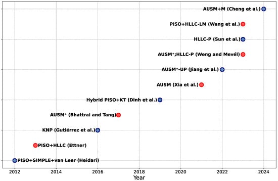
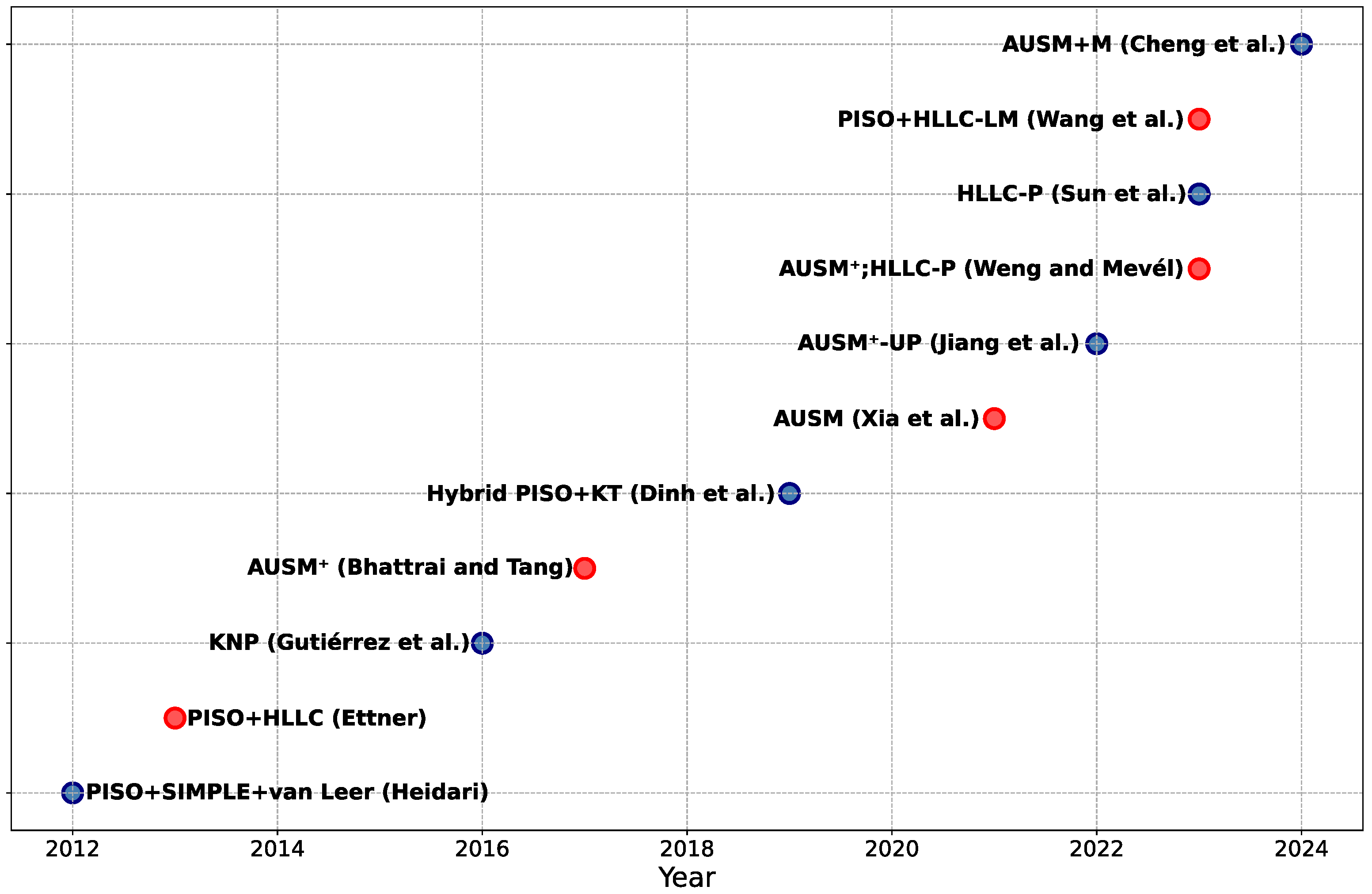
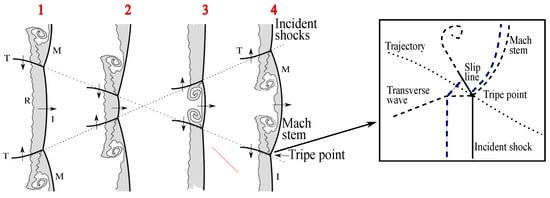
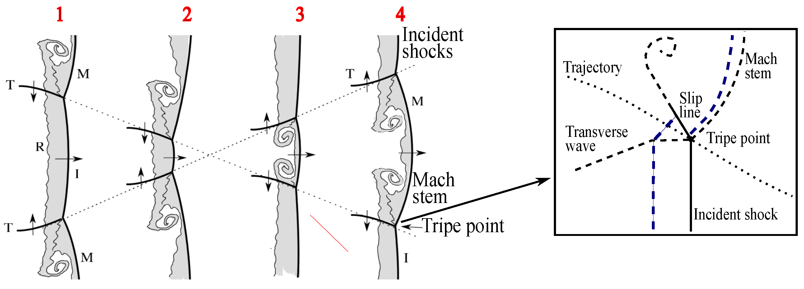
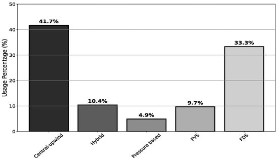
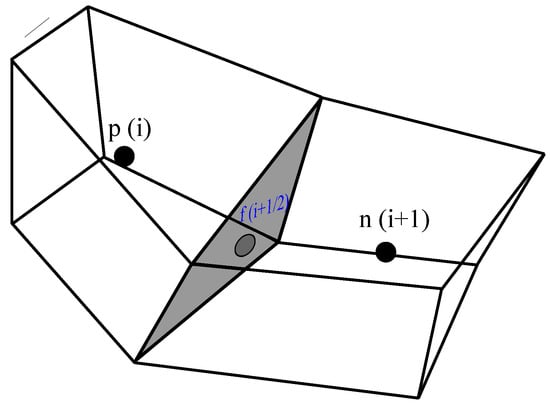
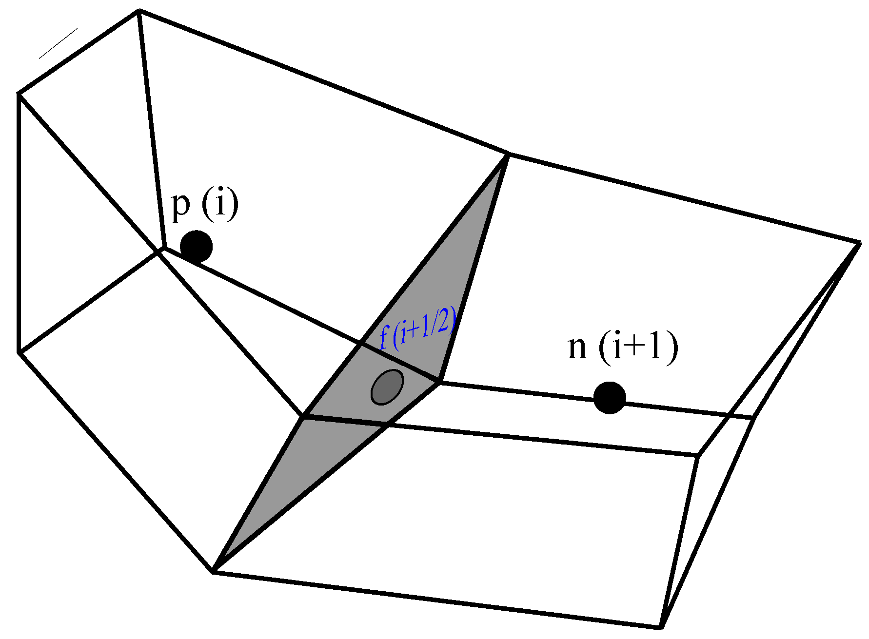
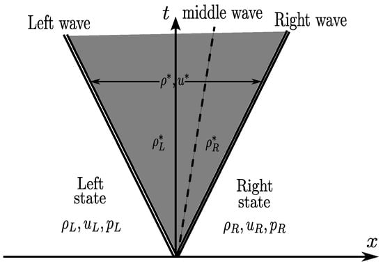
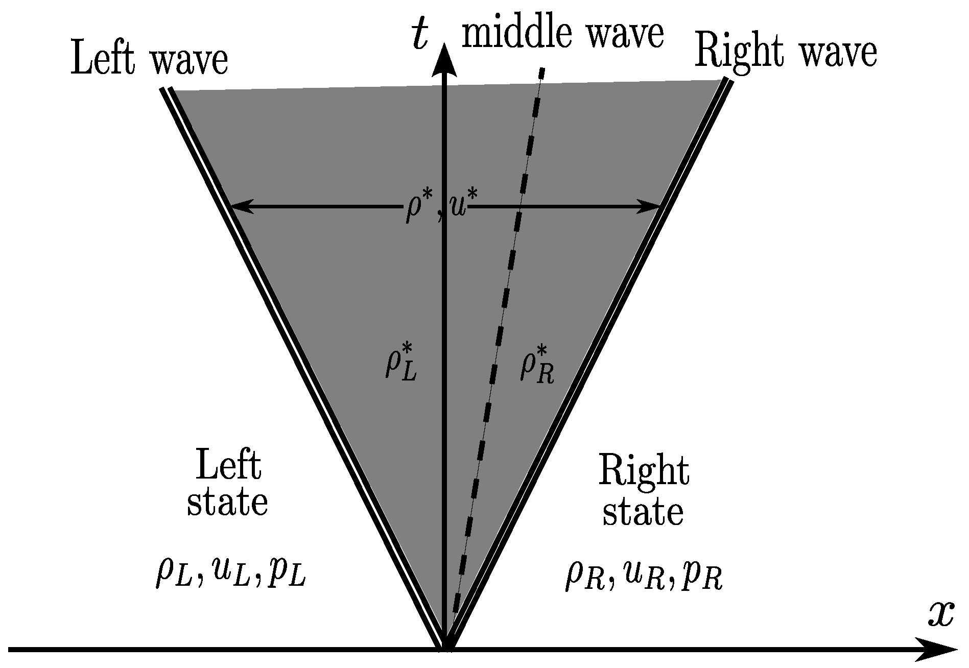
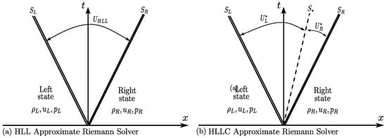
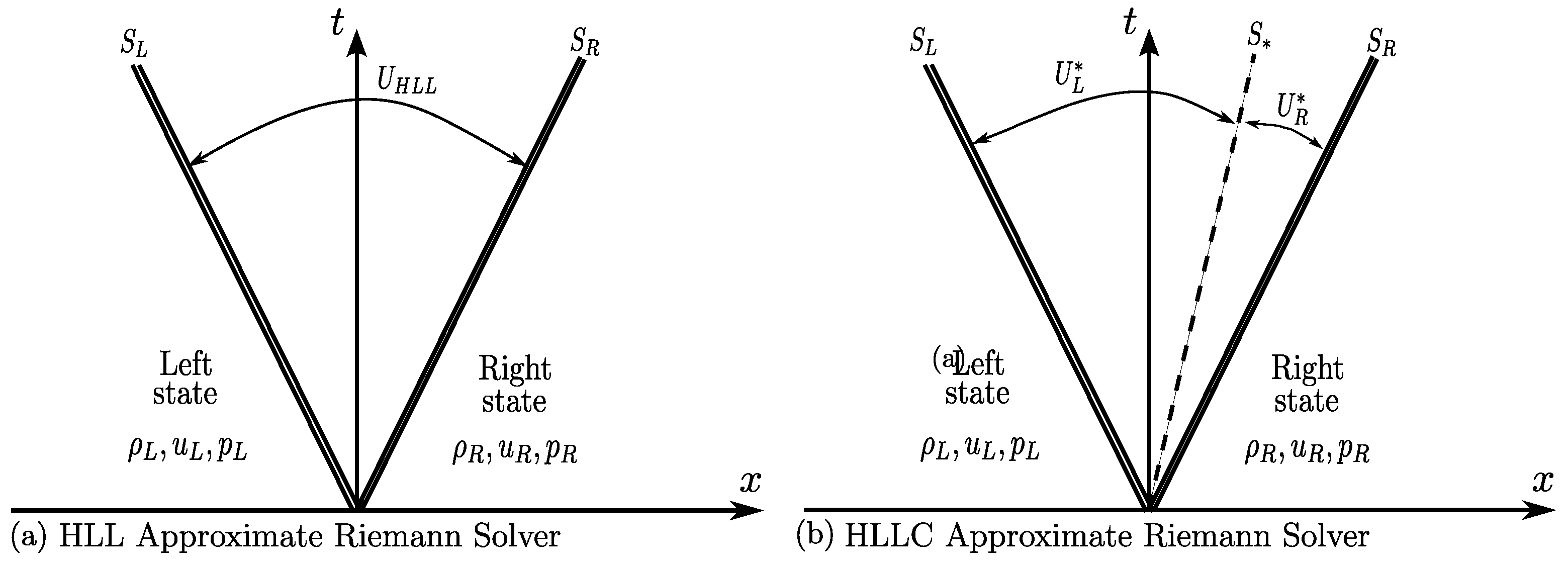

Disclaimer/Publisher’s Note: The statements, opinions and data contained in all publications are solely those of the individual author(s) and contributor(s) and not of MDPI and/or the editor(s). MDPI and/or the editor(s) disclaim responsibility for any injury to people or property resulting from any ideas, methods, instructions or products referred to in the content. |
© 2026 by the authors. Licensee MDPI, Basel, Switzerland. This article is an open access article distributed under the terms and conditions of the Creative Commons Attribution (CC BY) license.