Article

3D Geological Model and Interpretation of Structural Evolution of the Masa Valverde VMS Deposit, Iberian Pyrite Belt (Spain)

1
Consulting de Geología y Minería (CGM), S.L., C/Vista de la Ermita 1, 45930 Mentrida, Spain
2
Atalaya Mining, La Dehesa s/n, 21660 Minas de Riotinto, Spain
3
Department of Geology, University of Oviedo, C/Arias de Velasco s/n, 33005 Asturias, Spain
4
Department Geology, Ibercreta Group, University of Alcalá, 28805 Alcalá de Henares, Spain
*
Author to whom correspondence should be addressed.
Minerals 2026, 16(8), 832; https://doi.org/10.3390/min16080832
Submission received: 7 July 2026 / Revised: 29 July 2026 / Accepted: 6 August 2026 / Published: 11 August 2026

Abstract

This study presents a 3D geological model and structural interpretation of the Masa Valverde volcanogenic massive sulfide (VMS) deposit in the Iberian Pyrite Belt. The deposit is hosted by felsic porphyritic volcanic rocks, volcanic tuffs, and black shales. A 3D geological model of the orebodies and host rocks, constructed from 145 drill-core logs, allowed us to build 16 cross-sections spaced 100 m apart and constrain the mineralization geometry and its structural evolution. Mineralization formed during Early Carboniferous transtensional tectonics within an extensional basin, where an extensional duplex structure controlled the development of the primary massive sulfide body and its associated stockwork. Subsequent counterclockwise rotation of the principal stress axes reactivated extensional faults as reverse faults during tectonic inversion. This deformation strongly modified the VMS system through buttressing, generating extensive open spaces, and promoting the brecciation and recrystallization of both the stockwork and massive sulfides. These processes produced a new paragenesis dominated by chalcopyrite and sphalerite, with minor galena among other minerals, which cemented the breccias, partially replaced earlier mineral assemblages, and filled open fractures. The resulting Cu-Zn enrichment, spatially associated with buttressed zones, provides new insights into ore remobilization with direct implications for the development of the ongoing underground mine.

1. Introduction

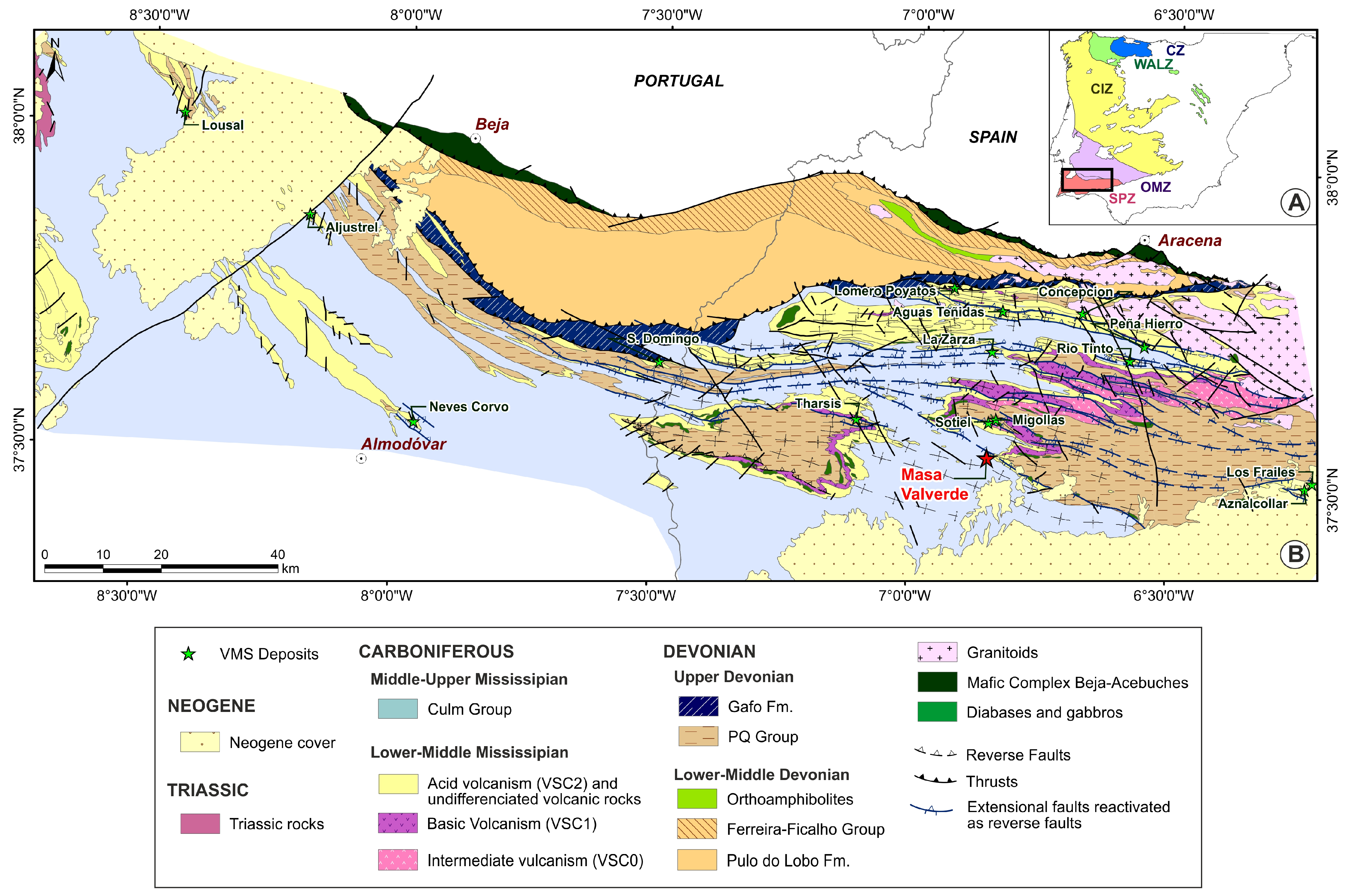
The Iberian Pyrite Belt (IPB) extends from Portugal to Spain, covering an area of around 250 km by 60 km (approximately 8000 km2), and is located in the South Portuguese Zone (SPZ, Figure 1A) of the Iberian Massif. In its central part, the SPZ contains the greatest known concentrations of volcanic-hosted massive sulfides (VMSs) on Earth. The IPB contains over 100 massive sulfide and stockwork deposits, including over 10 giant (world-class) deposits with more than 50 million metric tons (Mt) of ore each, and many more small prospects (Figure 1B). Examples of these deposits can be found in [1,2,3,4,5,6,7,8], among numerous other papers.
As indicated by [4], there are currently seven operational mining centers: five in Spain (Las Cruces, Rio Tinto, Sotiel, Magdalena, and Aguas Teñidas) and two in Portugal (Aljustrel and Neves-Corvo). Some other projects are in the design and permitting phases for exploitation: Los Frailes (Grupo Mexico), Concepción (MATSA), and Masa Valverde (Atalaya Mining). This work is centered on the last: Masa Valverde.
With regard to the origin of the massive sulfide deposits, several authors have recently proposed that a transtensional faulting tectonic process during the early Carboniferous (between 360 and 350 Ma [9]) favored the emplacement of volcanic rocks through the accompanying fractures. These proposals include those by [2,6,7,10,11,12]. Furthermore, some authors have proposed that certain deposits within the IPB metallogenic province were formed in relatively confined basins [2,8,11,12,13]. The general acceptance of these propositions is demonstrated by the findings of [8,14], which clearly show a relationship between fractures/faults and ores.
Figure 1. (A) The zones of the Iberian Massif. CZ: Cantabrian Zone. WALZ: West Asturian-Leonese Zone. CIZ: Central Iberian Zone. OMZ: Ossa Morena Zone. SPZ: South Portuguese Zone. (B) Geological map of the Iberian Pyrite Belt (IPB) with the location of the main massive sulfide deposits. The geological basis is from [12].
Minerals 16 00832 g001
It is well-established that IPB deposits are characterized by the presence of pyrite- and chalcopyrite-rich stockworks and massive sulfides, both pyritic and complex, and that they host volcanic and sedimentary rocks (mainly black shales) [1,5,9,15,16,17,18,19,20]. However, the relationships between these elements and the transtensional tectonics claimed for their genesis have only been integrated in the Rio Tinto deposit [11]. Subsequently, Ref. [12] proposed an extension of the Rio Tinto model to encompass the entire IPB.
Transtensional tectonics, as defined by [13], is thoroughly explained in the Rio Tinto area. This phenomenon occurred across the entire IPB between 360 and 350 Ma, as documented by [2,6]. Several authors have employed transtension to elucidate specific aspects of the IPB, such as the following:
  • The geographical location of the deposits [5] falls within two domains, northern and southern.
  • The impact of fractures/faults on the fractal distribution of deposits in the Spanish sector has been thoroughly examined by [8,14].
  • Two different styles of mineralization have been identified: shale and volcanic-hosted orebodies [20,21].
  • The age of the deposits varies across different sectors. As Refs. [9,22] have noted, the age of deposits varies across different sectors, with some sectors containing younger deposits and others older deposits.
  • The regional distribution of trace elements in the ores of the Spanish sector [21].
  • The low dispersion in the lead isotopic composition, as referenced in [23].
It is also crucial to highlight that following this transtensional phase, the Variscan Orogeny occurred, subjecting the entire IPB to subsequent transpression. Consequently, mineralization, along with the associated host rocks and structures, experienced significant superimposed deformation, often complicating the identification of the preceding transtensional period [12,24,25].
The Masa Valverde VMS deposit was discovered in 1986 and has been studied by several authors (e.g., [26]). According to Refs. [11,12], who presented a new model for the IPB VMS deposits, we conducted a detailed study of the Masa Valverde deposit. This study includes the following: an analysis of its volcanic–sedimentary sequence, tectonic evolution during both the transtensive and transpressive periods, the present 3D geometry of the bodies and host rocks, and a proposal of the evolution of the deposit during both tectonic periods.
Masa Valverde’s work clearly demonstrates a relationship between the evolution of fractures and ores. Additionally, the geometry and relationships between the deposits and transtensional tectonics are well-understood, including the formation of an extensional duplex. In fact, we provided a detailed interpretation explaining the structural control during ore formation using the 3D modeling technique, which has been proven to be very useful for solving many geological problems, as indicated by [11,12,27]. In these papers, the authors indicate that this 3D modeling technique, in combination with classical studies such as petrography or geochemistry, helps achieve a better understanding of the structural configuration of the deposits and provides guidelines for prospecting. It also helps improve the evaluation and exploitation of these VMS deposits.
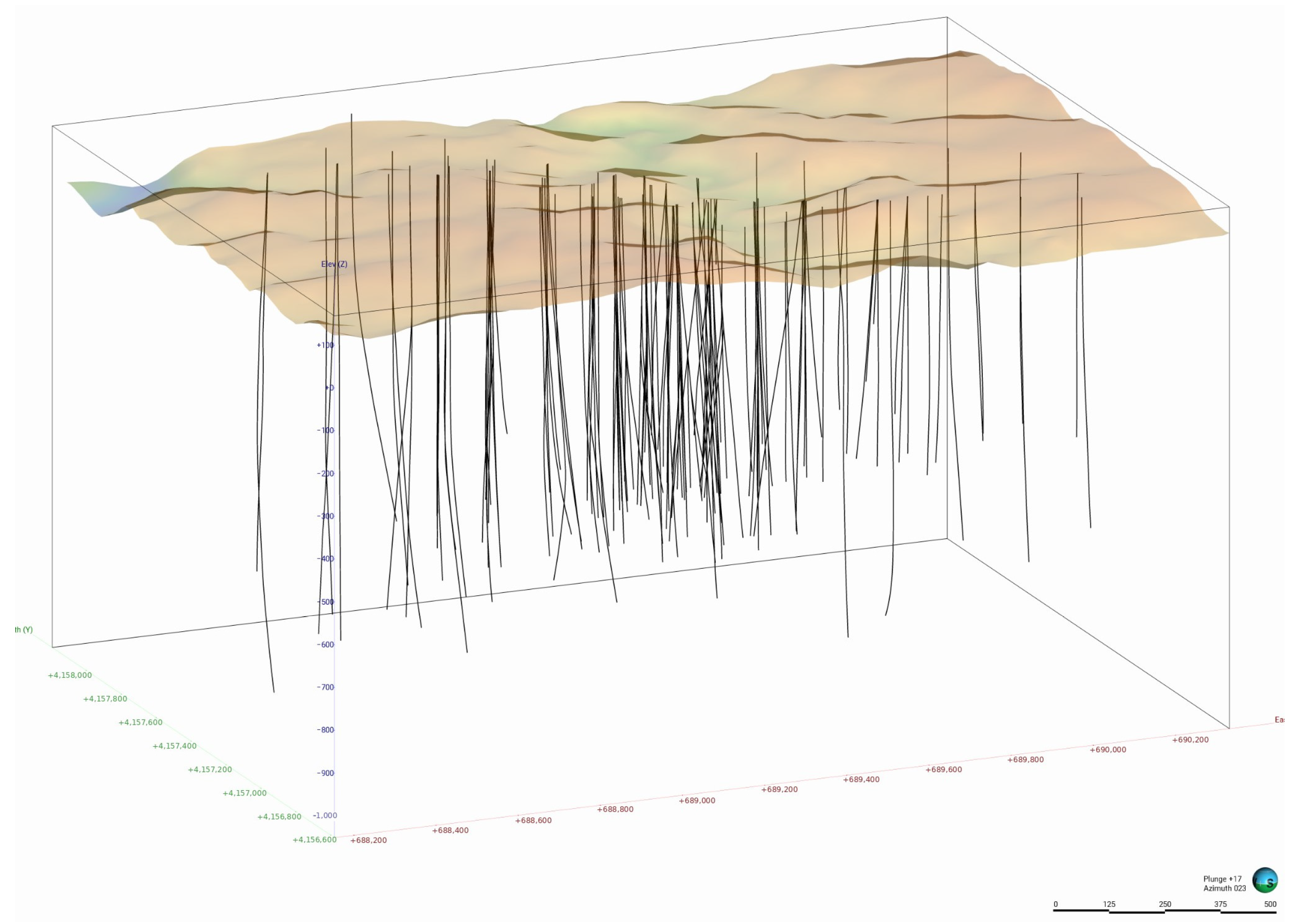
To achieve this objective, we had access to 145 drill-core logs (Figure 2). Of these, 25 logs were from Adaro, 43 logs were from Glencore, and the remainder were from Atalaya. We obtained approximately 106,706 m of core.
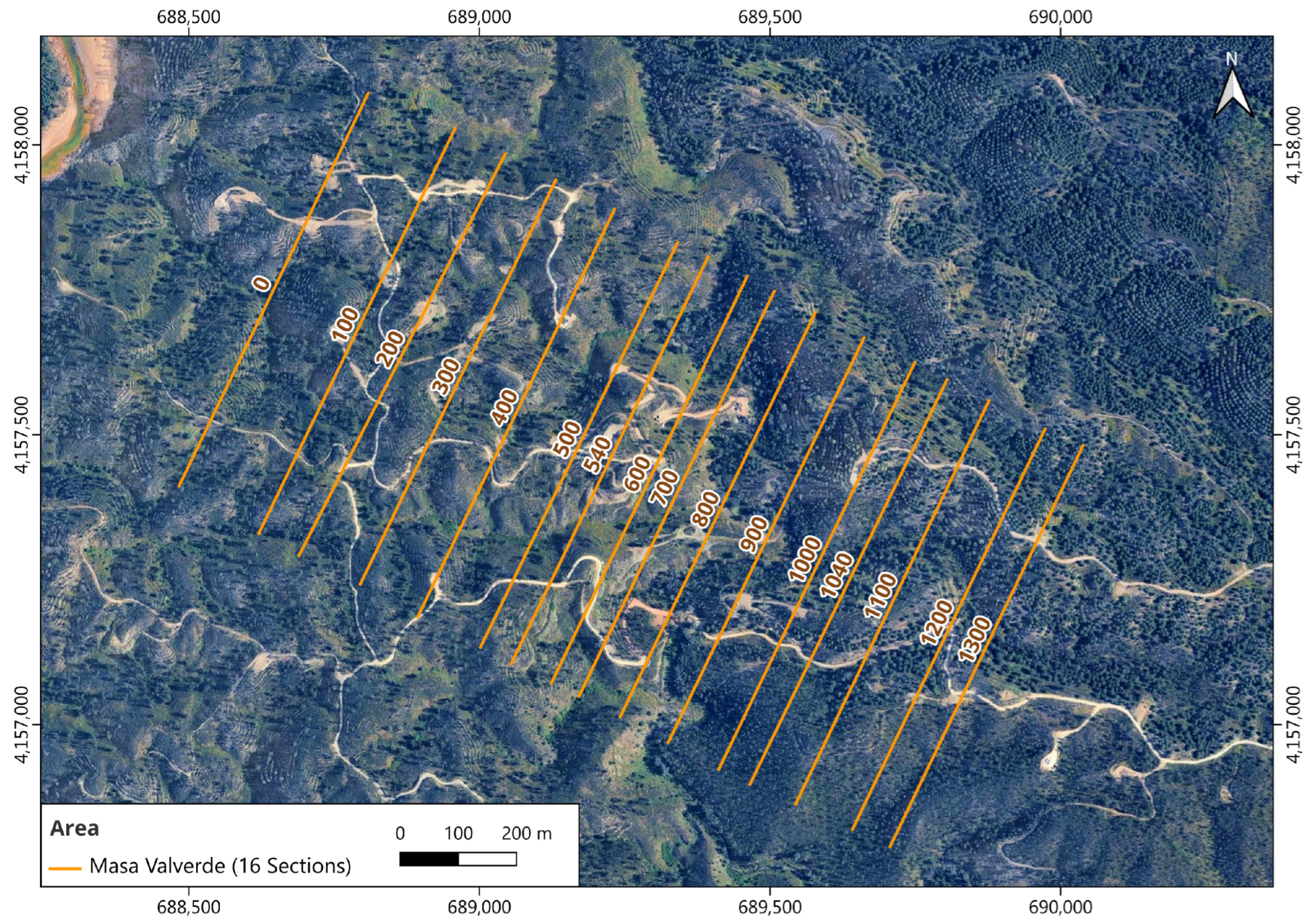
The logging of these boreholes enabled the creation of 16 geological cross-sections (Figure 3), one horizontal section, and the subsequent 3D modeling, which is presented for the first time in this work. We define two types of pyritic stockwork: one occurs when the S content exceeds 30%, and the other occurs when it is below 30%. Cupriferous veining is defined as the presence of Cu content that surpasses 1%. In fact, stockworks and veining are much more broadly extended, but we set these cut-offs because they are the limits of the evaluation criteria.

2. Mineral Exploration

The Masa Valverde deposit, located in the Iberian Pyrite Belt (Huelva, SW, Spain), constitutes one of the most significant blind polymetallic sulfide discoveries in the region. The deposit was discovered in July 1986 by a joint venture between the Empresa Nacional Adaro and Peñarroya. The first discovery drillhole intersected approximately 96 m of massive sulfides at a depth of about 434 m beneath the Culm. Subsequent exploration campaigns (1986–1993) relied on the integration of residual gravity, magnetic, and electromagnetic surveys followed by systematic diamond drilling. Around 25 drillholes confirmed a large, elongated orebody exceeding 1 km in length, plunging 30° toward NW, and hosted within a volcano–sedimentary sequence of felsic tuffs and shales and buried at depths between 400 and 850 m [26]. These results established Masa Valverde as a key example of deep VMS mineralization and contributed significantly to exploration models targeting concealed deposits in the IPB.
The project was originally granted to Cambridge Minería España (CME) in 2013. During its tenure, CME focused primarily on the integration and reinterpretation of historical exploration datasets generated during the discovery phase. This included an analysis of the historical drillholes. These datasets confirmed a large, deeply buried orebody (>1 km in strike length) hosted within volcano–sedimentary sequences and characterized by polymetallic sulfides dominated by pyrite, with economically relevant concentrations of Cu, Zn, and Pb. Although CME conducted limited new drilling, its work was critical in defining geological continuity, structural controls, and resource potential. CME estimated the massive sulfide and cupriferous stockwork orebodies to have resources of approximately 100 Mt and 50 Mt of ore, respectively [28].
A significant advancement was marked by the entry of Atalaya Mining in 2018, which initiated systematic and large-scale drilling campaigns. These surveys targeted both infill and step-out drilling, with the dual objective of upgrading resource confidence and expanding mineralization. Results from these campaigns confirmed thick massive sulfide intersections (locally exceeding tens of meters) and identified zones with elevated Zn grades (commonly >5 wt.% Zn, locally higher), associated with variable Cu (typically 0.3–1 wt.% Cu) and Pb contents.
Also, Atalaya’s exploration led to the discovery of the Majadales satellite deposit, located approximately 1 km from the main Masa Valverde orebody. Drilling at Majadales intersected additional massive sulfide lenses with comparable metal contents, demonstrating the presence of a clustered VMS system rather than an isolated deposit. Since 2018, Atalaya Mining (ATM) has performed 65 drillholes, with a total of 106,706 m, and analyzed 16,560 samples. All of these data have permitted Atalaya [29] to define a resource of 90.3 Mt with an average Cu of 0.62%, Zn of 1.30%, and Pb of 0.62%.

3. Regional Geology

The IPB is part of the Iberian Massif (Figure 1A), which resulted from the convergence of three continental blocks: the South Portuguese Zone (SPZ), the Ossa Morena Zone (OMZ), and the amalgamation of the Central Iberia Zone (CIZ), West Asturian–Leonese Zone (WALZ), and Cantabrian Zone (CZ) [11,12]. These blocks all originated from the fragmentation of a Late Proterozoic megacontinent [30]. According to the research by Refs. [11,12], the IPB, which is part of the SPZ, was formed as a series of marine basins that developed during the left-lateral transcurrent faulting generated by the oblique subduction and collision of Laurentia with Gondwana during the Variscan (Late Devonian–Early Carboniferous [2,31]). These basins coexisted with a mantle plume, as indicated by [6]. These basins were formed within the passive margin of Laurentia, which is now represented by the SPZ and adjacent to the continent–continent suture.
The oldest rocks in the IPB (0B) are a sequence of Late Devonian quartz-rich sandstones and shales (the Phyllite–Quartzite Group, or PQ), which were deposited on a stable epicontinental shelf [32]. The overlying Volcanic Sedimentary Complex (VSC), which hosts most of the mineralization, is a highly variable unit with a thickness of up to 1300 m. The age range of this formation extends from the uppermost Devonian to the middle Visean period, spanning approximately 360 to 350 million years ago [6,9,31,33,34]. The VSC is characterized by dacitic–rhyolitic dome complexes and sills, basaltic lava flows and sills, and thick, pumice- and crystal-rich, felsic volcanoclastic units, which are interbedded with detrital sedimentary rocks (predominantly mudstone, with some greywacke and sandstone [35]). The depositional environment appears to be dominated by submarine mass-flow tuffs, as indicated by [32]. An approximately 10-m-thick horizon of hematitic, radiolarian-rich, purple shale with manganese-bearing jasper lenses is stratigraphically high in the volcanic–sedimentary sequence. This horizon has been used as a local correlation marker in some areas of the IPB [2,21,35,36,37]. The VSC is overlaid by the Flysch Group (Culm), which consists of synorogenic turbidites of late Visean to Middle-Late Pennsylvanian age [2].
The earliest Carboniferous period (approximately 360 to 350 million years ago) was a transient period characterized by extension and hot spots related to I-type magmatism (Simancas et al., 2003 [6]). Abundant bimodal volcanism and extensive VMS mineralization development occurred mainly along fracture zones that limited different basins [2,11,12]. The faults responsible for crust thinning and basin formation developed in a left-lateral transtensional regime in a continental passive margin [3,11,12,31,38]. Some of these basin-forming faults reactivated as reverse faults, accompanied by a buttressing phenomenon, during the subsequent Variscan shortening [2,8,11,12,16,25].
In the transtensional scenario, on a very large scale controlled by fracture systems, different types of volcanogenic massive sulfide (VMS) deposits formed. The largest of these deposits were probably controlled by larger, more active, and better-connected faults that developed over an area heated by a mantle plume [6]. According to the works of [8,11,39], the majority of massive sulfides are found over or near stockworks within an aureole of hydrothermal alteration. This hydrothermal alteration, which predates regional metamorphism, was caused by focused hydrothermal activity dominated by modified seawater [17,37,40]. The majority of well-studied stockworks appear to be controlled by faults and stratigraphic layers [8,11,12,14,39]. Stockworks are linked to zoned alteration, usually showing an internal chlorite-rich zone surrounded by a sericitic or propylitic zone. Silicification is a frequent alteration process, and carbonatization has also been observed [8,21].
Volcanic rocks primarily occur in depositional environments dominated by submarine mass-flow tuffs, with some lava, hydroclastic rocks, and volcanogenic sediments. Shallow intrusions, including peperites, are scarce throughout the IPB. Most basaltic rocks are continental tholeiites, although a few samples show an alkaline affinity [2,11,12,32,35,40,41,42]. The origin and diversity of the composition of the basaltic rocks are explained by a single mixing model involving E- and N-MORB (mid-ocean ridge basalt), which is consistent with a mantle plume [43] and the assimilation of crustal material. Intermediate calc-alkaline and silicic rocks include basalts, basaltic andesites, dacites, and rhyolites. However, intermediate and silicic rocks are not related through fractional crystallization, nor are basaltic and calc-alkaline rocks related through this process [41].
Some authors [5,41] have suggested that silicic calc-alkaline magmas were generated on a large scale through the invasion of continental crust by mafic magmas originating from the underlying upper mantle. These magmas may follow the model proposed by [6]. The diverse compositions of dacites and rhyolites can be explained by differences in source rock composition or by varying degrees of the partial melting of upper crustal rocks. Zircon morphology indicates that IPB acid magmas are of crustal origin [44]. However, the mixing of basaltic magmas and upper-crust material [41,45] formed andesites. As Ref. [42] indicated, the diversity of volcanic lithofacies recognized in different areas of the IPB reflects variations in proximity to the source as well as differences in eruptive style. The sedimentary sequence in the IPB is complex, and the irregular geometry of the volcanic–sedimentary sequence can be attributed to the geometry of the basins and the distribution of volcanism and sedimentary facies within them [2,35,41,42]. Four sequences (VSC0 to VSC3) are present throughout the IPB [11,12], but their thickness and abundance vary significantly from one location to another. Reference [12] adopted the sequence established by [46], modified as the simplest yet most realistic. They also assumed natural lateral variations, vertical complexity, and the local absence of some expected terms in a volcanic–sedimentary depositional environment constrained by a complex tectonic setting, such as the IPB. From bottom to top, the sequence is as follows:
  • VSC0: The initial andesitic to felsic volcanism is characterized by the presence of interbedded black, tuffaceous, and cherty slates that host massive sulfides (Figure 1B).
  • VSC1: This is a basic rock formation of basaltic composition, characterized by intercalated black slates and conglomerates, with the latter becoming more prevalent toward the top of the formation.
  • VSC2: Acid volcanic (rhyolite and dacite) rocks hosting massive sulfides are present at the top of the sequence (Figure 1B).
  • VSC3: Characterized by purple slates and barren acid volcanism.
The Culm Group, which consists of syn-orogenic flysch sediments, covers the entire volcanic–sedimentary complex. Furthermore, stockworks in many IPB deposits represent feeder zones to more massive mineralization [39].
Structurally, the Iberian Pyrite Belt is considered a south-verging belt that propagated southward [7,47]. Variscan deformation in the SPZ began with the oblique collision of two continental terrains in a transpressional setting, producing an inversion of previous extensional structures developed in the transtensional stage [11,12]. The spatial correlation between faults and the location of mineral deposits [8,11,12,14] is primarily related to the early Carboniferous E–W fractures/faults generated by transtension. These structures were reactivated as reverse faults during the later Variscan transpression [11,12,25]. This results in a secondary spatial association that is genetically developed on or in close proximity to the VMS mineralization.
Finally, the metamorphic grade is typically very low, reaching only prehnite-pumpellyite facies. However, in the northern part of the IPB, deformation is more intense, and the rocks recrystallize within green schist facies [40]. This metamorphism overprints the alteration associated with mineralization.

4. Materials and Methods

4.1. Mineralogy and Petrography

The completion of this study was made possible by access to 145 drill-core logs from the Masa Valverde area (Figure 2). We re-examined drill cores produced by various mining companies to standardize the logging criteria and to carry out detailed sampling of both the ore-bearing rocks and the host rocks of the deposit. Selected samples were prepared as polished thin sections for mineralogical, petrographic, and mineral geochemistry. Approximately 100 samples were studied using transmitted and/or reflected light microscopy, as well as SEM-EDS, at Oviedo University (Oviedo, Spain).
The total resources estimated by the company were 90.3 Mt, with an average Cu content of 0.62%, Pb 0.62%, and Zn 1.30% [28]. For this estimation, they used the 3D geostatistical model called the “empty block model”, created with cell dimensions of 10 × 10 × 10 m and comprising massive sulfides, but no 3D geological model was used. The evaluation method, uncertainties, and results are available on the web at [29].

4.2. The Generation of the Masa Valverde 3D Geological Model

The use of 3D geological models to facilitate the understanding of surface and sub-surface geology is well-established by many authors (i.e., [11,48,49,50,51,52,53,54,55,56,57,58,59]).
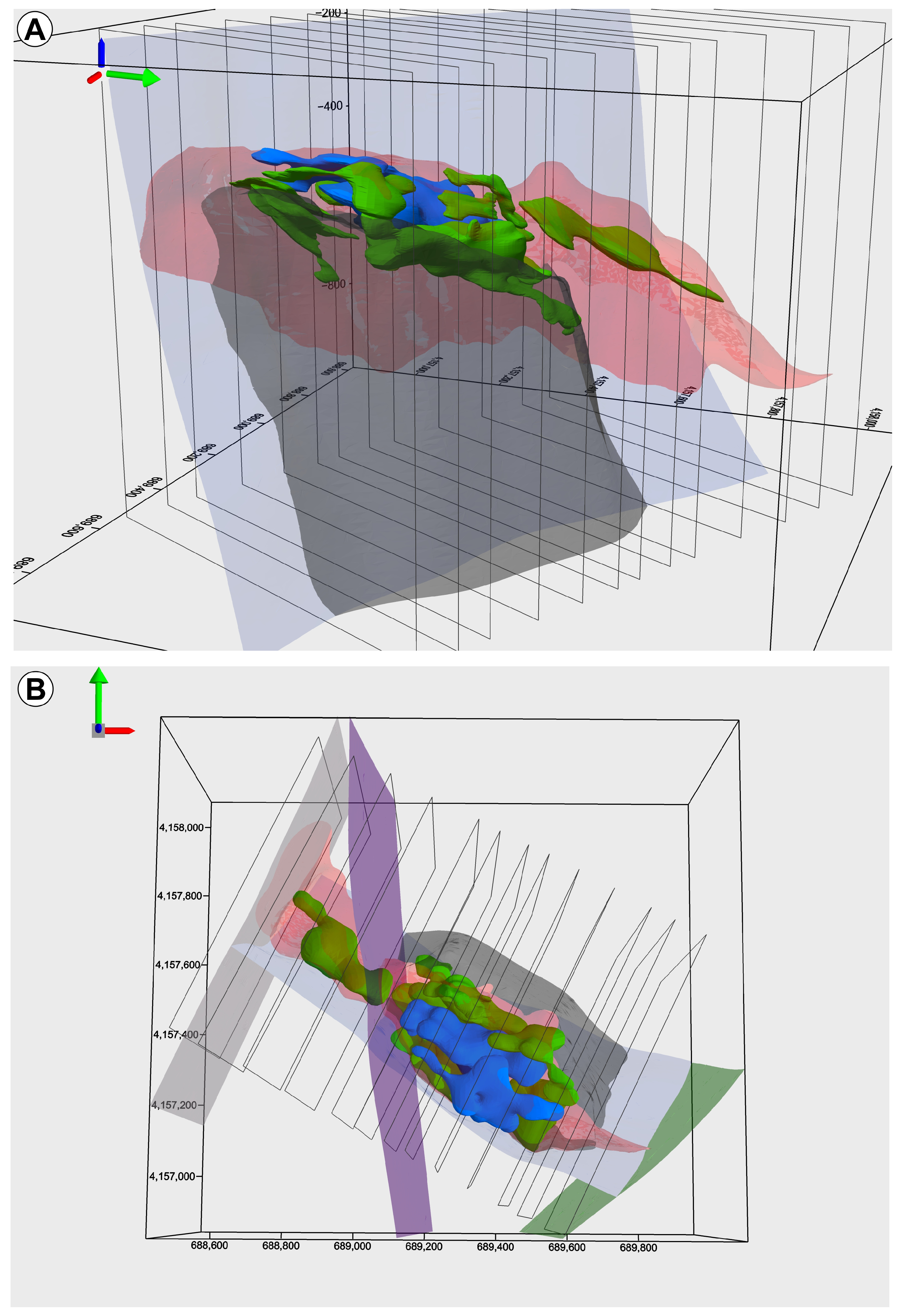
This paper presents two 3D models: first, the 3D geological model, created using Geomodeller, and second, the model of the Cu- and Zn-enriched zones, created using Leapfrog Geo.
The 3D geological modeling was generated using GeoModeller 1.3.822© (www.intrepid-geophysics.com), original software developed at the BRGM (French Geological Survey [60,61]). This software constructs subsurface models using an implicit, data-driven approach and integrates multiple data sources, such as structural measurements, drillholes, geological maps, and geophysical datasets, to produce continuous 3D representations of geological formations and faults.
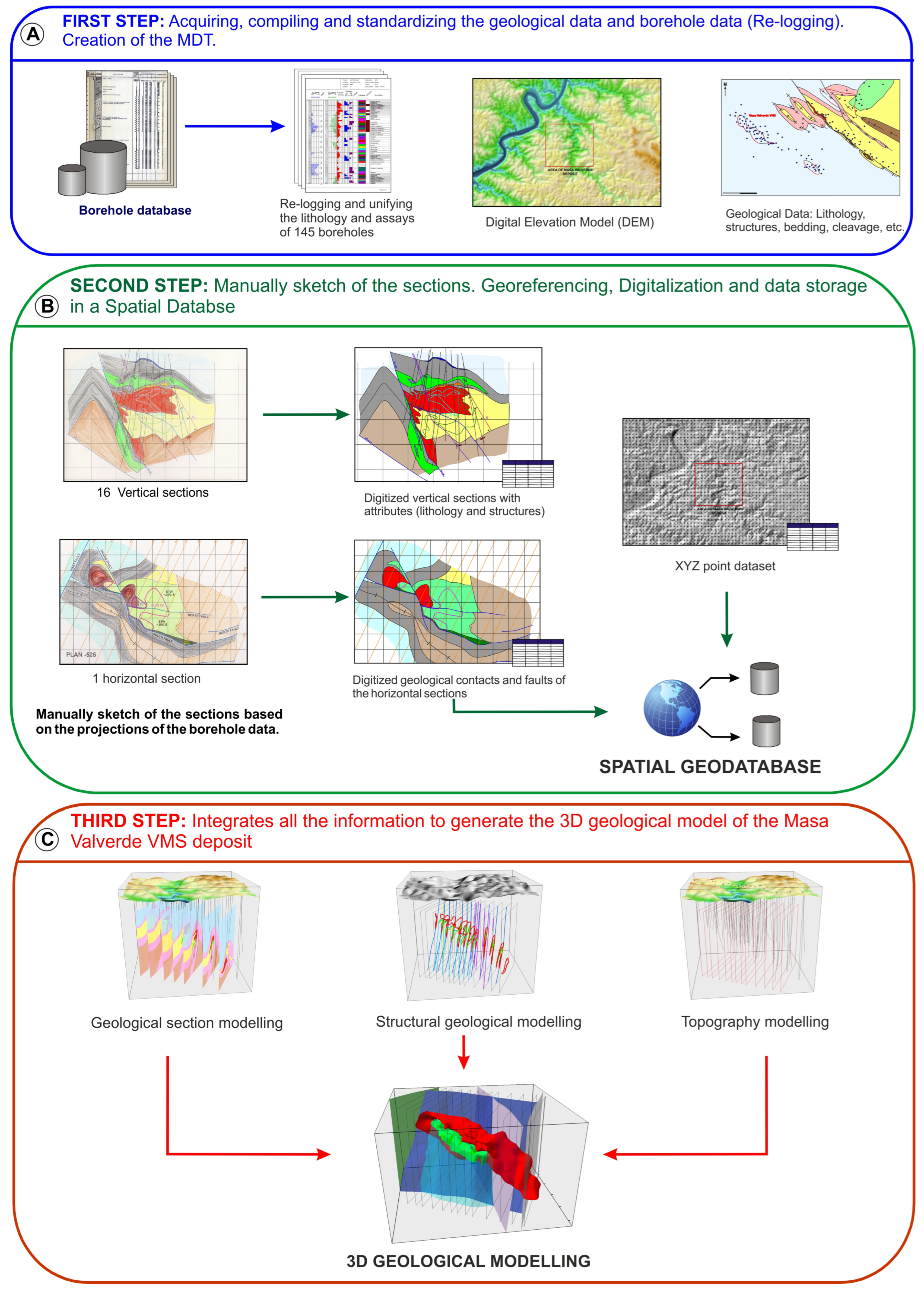
The methodology used in the Masa Valverde 3D geological modeling was implemented in a system consisting of a GIS, a spatial database, and 3D modeling software [52,55,56,58]. It involves several different steps for processing data, depending on the ore type (Figure 4A–C).
The first step was the generation of the digital elevation model (DEM) using the ArcGIS 10.8© software (Esri©, Redlands, CA, USA) to model the topographic surface. The geological information and borehole data were acquired, compiled, and standardized using Leapfrog Geo 2025.3.0 © (Seequent, a Bentley Systems company, Christchurch, New Zealand). The sources of the datasets are as follows.
Different drilling surveys performed from 1986 to those most recently carried out by Atalaya Mining were used to reconstruct the 3D geometry of the deposits. This involved access to 145 drill-core logs containing valuable lithological or structural information, and these drillholes were relogged in an attempt to unify the criteria used by different geologists in logging operations. We grouped all the different types of rock into the following lithologies: the PQ, gray and dark gray slates with interbedded volcanoclastic slates, rhyodacite, massive sulfides and copper stockwork, exhalites, and the Culm. We have determined that rock is classified as ore if it contains a copper content that exceeds 1%. In fact, mineralization is much more broadly extended, but we set this limit based on the evaluation criteria used by Atalaya Mining Company [29]. All borehole data (coordinates, depth, survey, lithological descriptions, assays, structural data, etc.) were stored in a database in which every hole had a unique identifier.
Topography was acquired at a 1:5000 scale from a topographical survey provided by the company.
Geological surface data were collected by the authors. Although surface mapping was used to constrain regional geology, it was not used as an input for the 3D deposit model itself, because the deposit is blind, concealed beneath a thick sequence of Culm turbiditic rocks.
Historical geological information on the surrounding mining areas was collected, and usable data were selected.
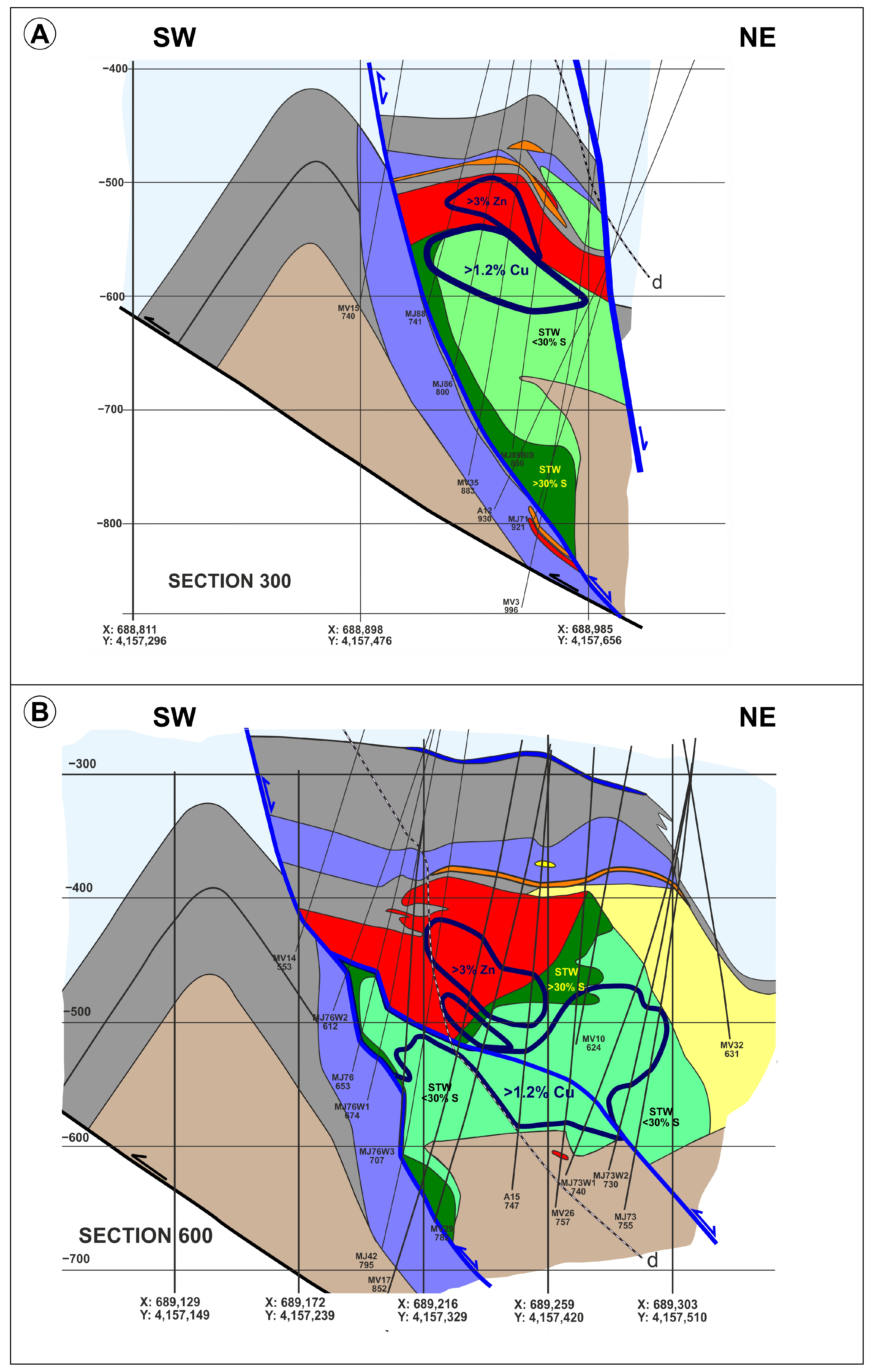
In the second step, 16 vertical NE–SW cross-sections were drawn by hand using the borehole data projected (10 m distance) on the sections (Figure 4B). Based on these, 1 horizontal section, at a 1:4000 scale, was generated. This methodology allowed us to produce a detailed construction of the structure of the deposit and is well-known in geology, often being applied to mineral exploration and mining [57,59].
The vertical and horizontal sections were georeferenced and digitized to produce the XYZ coordinates of each contact between the units and mineralized bodies defined in Step 1 and the geological structures. All of this digitized information, together with the structural data (dip and strike), was stored in a spatial database created in ArcGIS 10.8©. In this step, the use of an advanced GIS allowed us to check the topology rules in order to ensure geometrical consistency.
During Steps 1 and 2, a validation process was carried out to ensure that the data remained accurate and reliable while excluding any imprecise or uncertain entries from the dataset before modeling.
In the third step, all the geological data, cross-sections, borehole data, and DEM were imported from the database to GeoModeller©. Geological surface models were built using contact and dip vectors derived from the sections and plans.
In this software, lithological units are described as a pseudo-stratigraphic pile, intended to image geology and structural relationships as closely as possible. The software is based on geostatistical interpolation techniques, particularly co-kriging, which enable the generation of geological surfaces and volumes even in cases of sparse or incomplete data [50,56]. The geological contacts are isopotential surfaces, and their dips are represented by gradients of the potential, being isolines in 2D or isosurfaces in 3D [62,63]).
The large number of drillhole data allowed us to validate the geological subsurface objects because they were used as a depth constraint. Also, wireframe refinement was carried out with 2D polylines constrained to match the interpretation of the geological cross-sections. The final surfaces were accepted on the basis of internal consistency between all inputs—logged lithology, assay data, and the section interpretations.
Along with this geological and structural model, a 3D model of Cu and Zn enrichments is presented. These high-grade bodies were modeled using Leapforg Geo independently from the lithological and structural model described above: whereas the geological model references lithological units, the enriched bodies were built from the high-grade geochemical shells, and the two were computed as separate exercises.
High-grade domains were defined using grade thresholds of >1.2% Cu and >3% Zn, based on assay data from certified laboratories. Samples were used with their original support (no compositing was applied). The shells were defined principally by manual interpretation: each shell was checked graphically against the 2D cross-sections to confirm that it enclosed the selected high-grade samples and was locally adjusted with polylines where the fit was unsatisfactory. A radial basis function (RBF) numeric interpolant with default parameters was used as a supporting tool in this process.
The enriched bodies were deliberately not restricted to a single lithological domain, because high-grade intervals are in places shared between the massive sulfides, the stockwork zone, and the copper-veining zone.

4.3. Geology of the Masa Valverde VMS Deposit

The Masa Valverde deposit is located approximately 30 km southwest of Rio Tinto and about 8 km from the village of Valverde del Camino, in Huelva province.
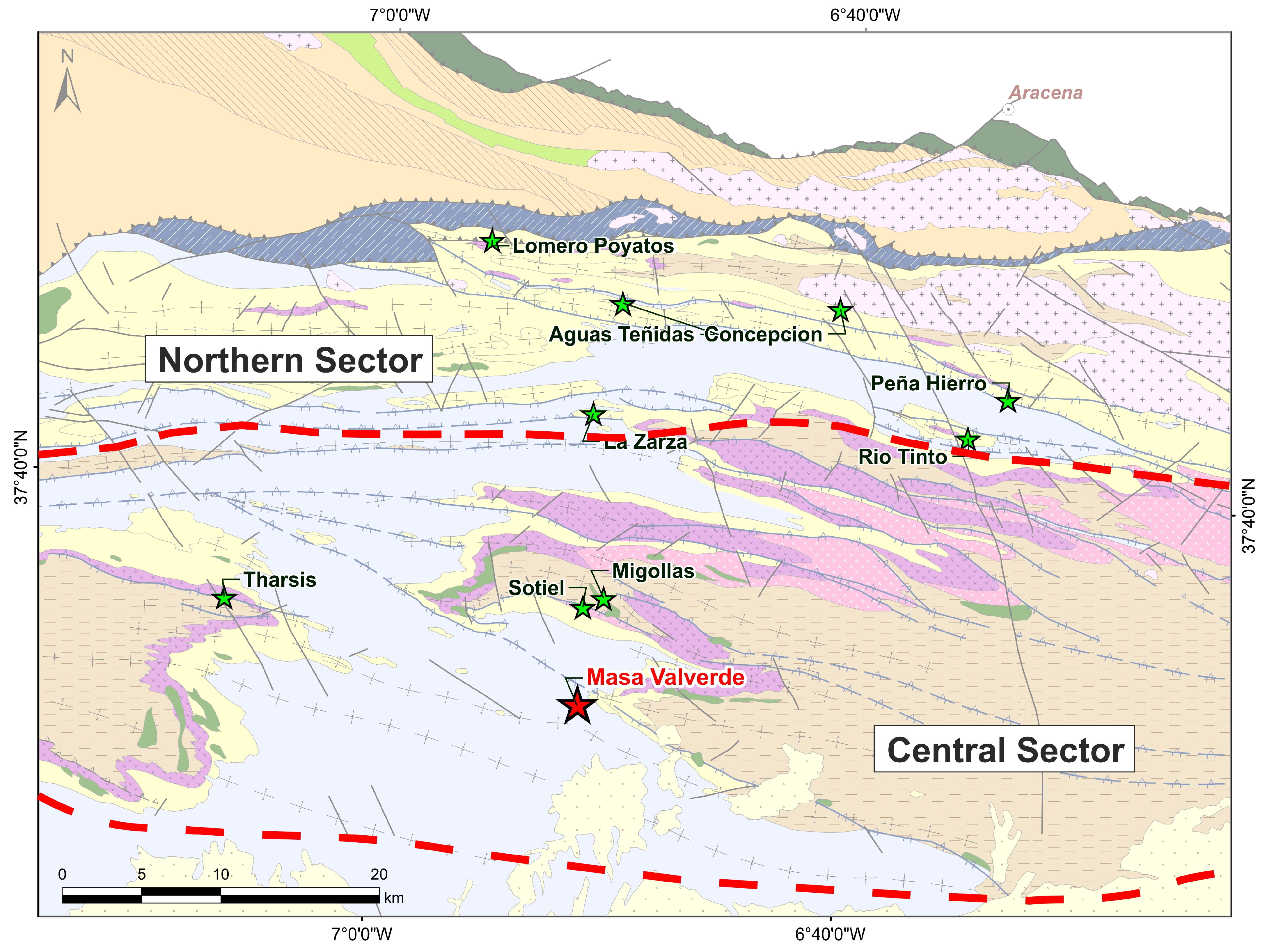
According to the schema proposed by [12], Masa Valverde is located in the Central sector of the IPB, extending in both Spain and Portugal. In this sector, half-graben structures are the most prominent. The primary deposits in this sector include Aljustrel, Lousal, Tharsis, Sotiel, and Aznalcollar, among others (Figure 5).
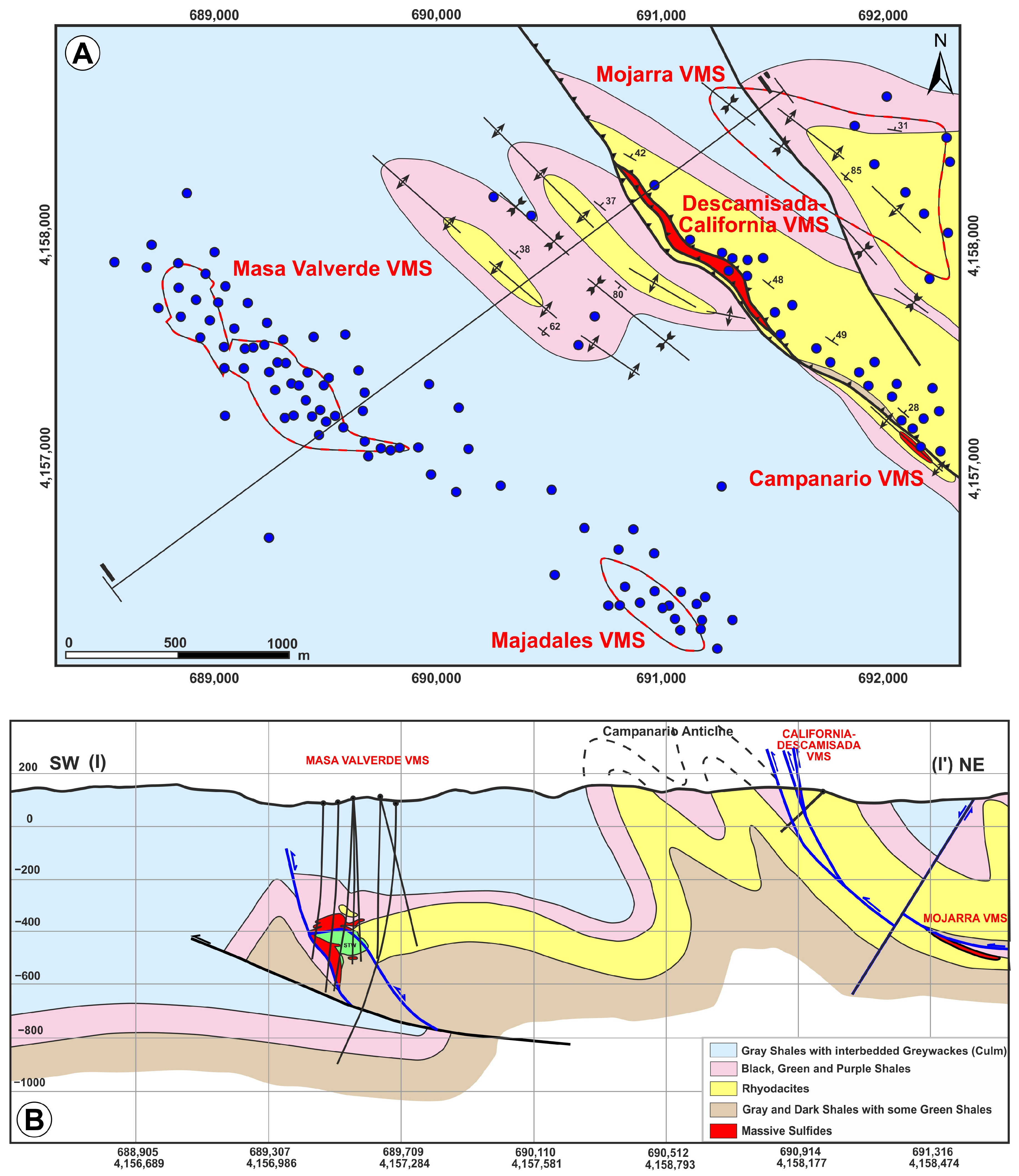
Masa Valverde is a non-outcropping deposit located beneath the Culm sediments in the Central sector, in the prolongation to the west of the Valverde anticline. According to [12], the only visible fracture system is located about two kilometers to the north and is an extensional fault that was subsequently reactivated as a reverse fault during the compressive event. The fracture system is associated with a group of small deposits that was previously mined in the 1920s under the names Campanario, Descamisada, and California, as well as two new bodies discovered by ATM between 2018 and 2020, named Majadales and Mojarra (Figure 6A,B).
The volcanics outcropping in the vicinity of Masa Valverde are situated to the south of the structure linked to the Campanario deposits and consist exclusively of acidic volcanic rocks from VSC2 and subsequent volcanism (VSC2 + VSC3) [12]. In the area, VSC0 and VSC1 outcrops north of the Campanario fracture, relatively far from Masa Valverde.

Stratigraphy of the Masa Valverde VMS Deposit

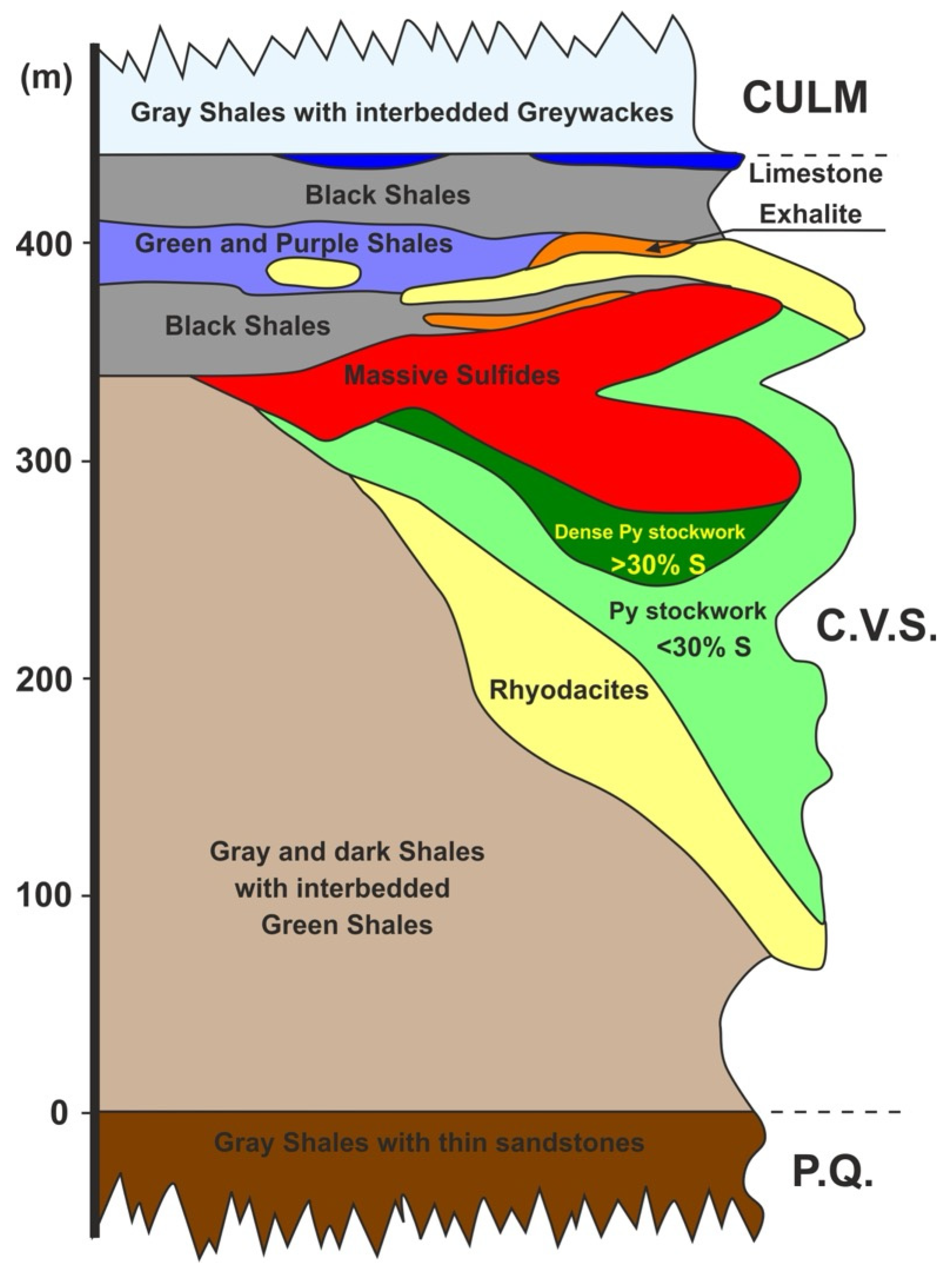
As with other regions of the Pyrite Belt, Masa Valverde’s formation was shaped by a transient period of extension during which shales and black shales were deposited, and hot spots linked to I-type magmatism emerged during the earliest Carboniferous period, approximately 360 to 350 million years ago. As illustrated in Figure 7, the volcanic sedimentary sequence in the Masa Valverde Basin is clearly delineated.
The sedimentary sequence in the hanging wall (downthrown) block (basin) formed during the extensional period is as follows.
Footwall volcanoclastic slates. They consist of gray and black slates with thin, green, cineritic slates interlayered between them, making up 10%–30% of the sedimentary sequence. The maximum thickness is around 180 m, and the lower contact is a thrust; thus, the real thickness is unknown.
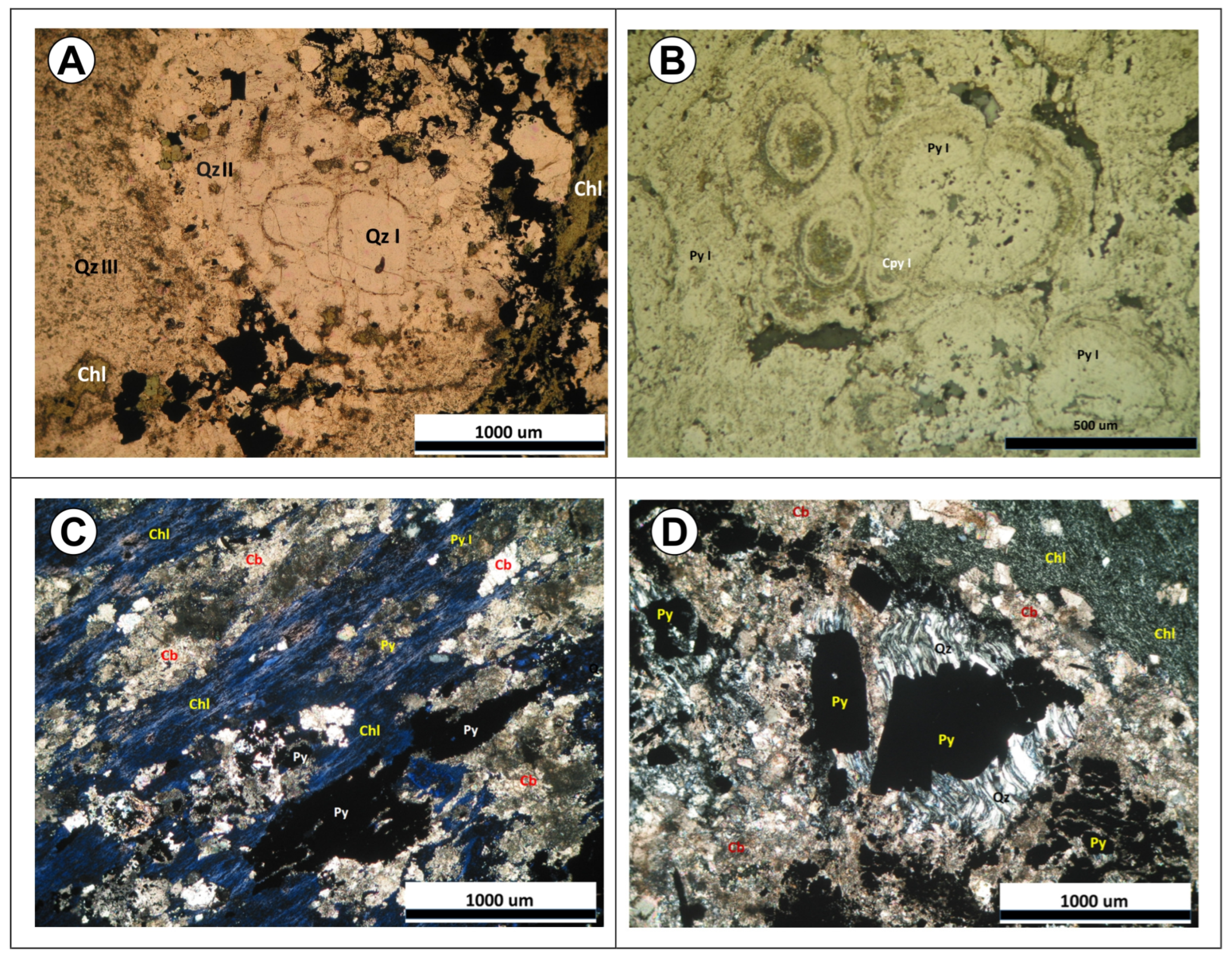
Rhyodacites. They constitute the acid rock sequence and are tuffs, agglomerates, and lavas with frequent intercalations of hyaloclastites. They appear to have been emplaced through the South Fault and accumulated in the sedimentary basin that developed to the north of this extensional fault. In the middle of the basin, they are up to 210 m thick. In the rhyodacite, several generations of quartz can be observed, as shown in Figure 8A, in which a primary quartz phenocryst (Q I) is overgrown with secondary quartz (Q II). The rock appears partially chloritized and silicified (Q III), accompanied by the deposition of sulfides.
Stockwork. Below the massive sulfides, the rhyodacites and some black shales related to them show an intense stockwork that is mostly pyritic.
The petrographic study of the stockwork yielded the following conclusions:
The samples studied are from a stockwork mostly developed on rhyodacites, and the vein system is primarily composed of pyrite.
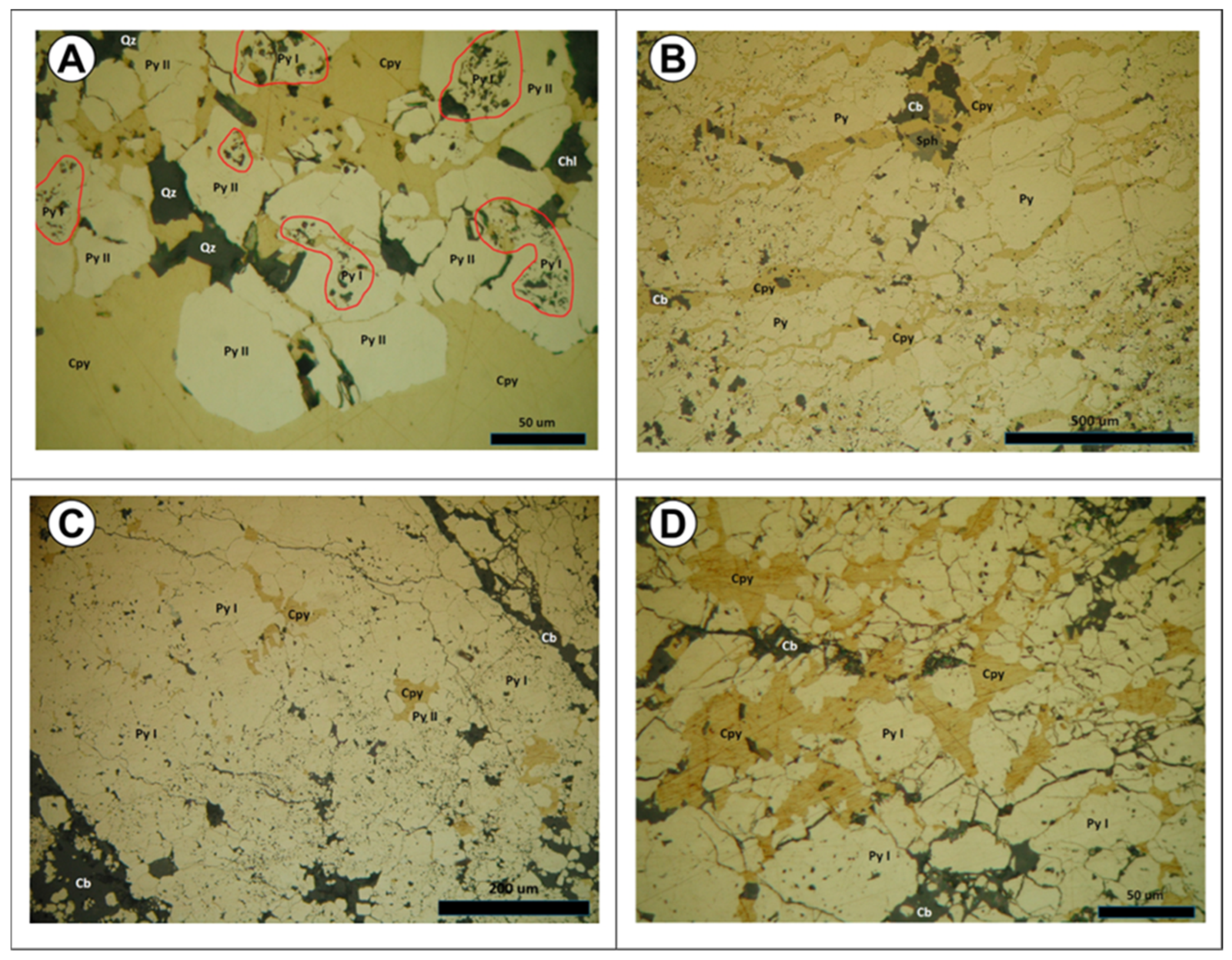
There are two types of pyrite in the primary stockwork: colloform pyrite (Py I), which contains numerous inclusions of phyllosilicates and organic carbon in which a planar fabric is sometimes beginning to develop (Figure 8B), and recrystallized, highly pure subidiomorphic pyrite (Py II) growing on pyrite I.
This stockwork shows significant levels of silicification and chloritization, also affecting rhyodacites. As explained in Section 5.1, this formation also featured carbonation, and the carbonates are dolomite patches and veins, along with minor ankerite.
Massive sulfides. They appear in the hanging wall of the South Fault, filling the upper part of the basin developed by the extensional fracture and partially replacing the rhyodacite. Their maximum thickness is located in the extensional basin, where it reaches up to 120 m.
The main features obtained from the petrographic study of the massive sulfides and carbonate-rich black shales are as follows:
  • The first metallic mineralization is primarily composed of colloform pyrite (Py I), with numerous inclusions of phyllosilicates and organic carbon, which contribute to its unclean appearance. This pyrite is indicative of sulfide precipitation from the brine pool in the VMS basin.
  • In the subsequent stage of the process, the colloform pyrite is recrystallized to a highly pure subidiomorphic form (Py II).
Exhalites and jaspers. The hanging wall of the massive sulfides frequently contains exhalites and jaspers in white, green, and red levels. Their thickness varies from several centimeters up to 8 m.
Hanging wall volcanoclastic slates. They are composed of gray and black slates with interlayered green and purple cinerites and are up to 120 m thick. Within these slates, a rhyodacite layer with the same composition as the massive sulfide footwall may appear. This level is discontinuous and lenticular, reaching up to 80 m in thickness, and can occasionally have a pyritic stockwork. Additionally, these slates may contain massive sulfides up to 2 m thick within the first 20 m, with some intercalated jaspers.
Black shales of transition to the Culm. Over the hanging wall volcanoclastic slates, there is a deposition of black shales with pyrite and some interbedded carbonate levels. Their maximum thickness occurs close to the extensional fault. It gradually diminishes farther away from the fault, disappearing to the north outside the sedimentary basin. The top of the black shales occasionally contains a thin layer of limestone that can reach a thickness of up to 5 m. The main characteristics of the black shales and their associated carbonates are as follows:
  • All of the samples exhibited a banded texture. They contain carbonate nodules with chlorite, sulfides, and quartz (Figure 8C,D).
  • Two different types of chlorites were identified: one dark green and one pale green.
  • As was the case with the massive sulfides, there were two types of pyrite: colloform pyrite (Py I), which contains numerous inclusions of phyllosilicates and organic carbon, and recrystallized, highly pure subidiomorphic pyrite (Py II).
This formation has been identified as a fossilized volcanic sedimentary sequence. However, it should be noted that there may be some thin green and purple cineritic and rhyodacitic volcanics present in certain areas approximately around 400–500 m over the VSC3.
Laminated gray shales with intercalations of grauwacke (CULM). The VSC sequence is fossilized. It is noteworthy that within the CULM, thin intercalations of green and purple cineritic shales may occur, among which thin layers of rhyodacite are occasionally intercalated. The presence of these volcanoclastic layers occurs primarily within the CULM, at approximately 400–500 m above VSC3, and may correspond to a local reactivation of acidic volcanism.
The stratigraphic sequence of the footwall block of the extensional fault is a condensed series in which the following units can be distinguished from the base to the top:
Footwall volcanoclastic slates. The slates present the same composition as in the downthrown block, with a maximum visible thickness of approximately 150 m. The lower contact is a thrust fault, indicating that the actual thickness is also unknown.
Hanging wall volcanoclastic slates. As observed in the downthrown block, the slates are composed of gray and black slates with interlayered green and purple cinerites, and they are up to 80 m thick. The slates in the vicinity of the South Fault may contain up to five meters of massive sulfides. The sulfides extend up to 20 m from the fault, covered by a meter-thick layer of jaspers. As evidenced in Cerro Colorado and Corta Atalaya in the Rio Tinto area [11], the sulfides may be indicative of minor synsedimentary masses of sulfides that sealed and overflowed the Southern fault.
It is noteworthy that this block (footwall) of the extensional South Fault exhibits an absence of rhyodacite levels and the black shales characteristic of the other sections.

5. Results

5.1. Structural Features of the Masa Valverde from the 2D Sections and 3D Geological Model

The main contribution of the 3D model and 2D sections across the Masa Valverde deposit is that they have facilitated the interpretation that the VMS mineralization formed within extensional faults reactivated as reverse faults.
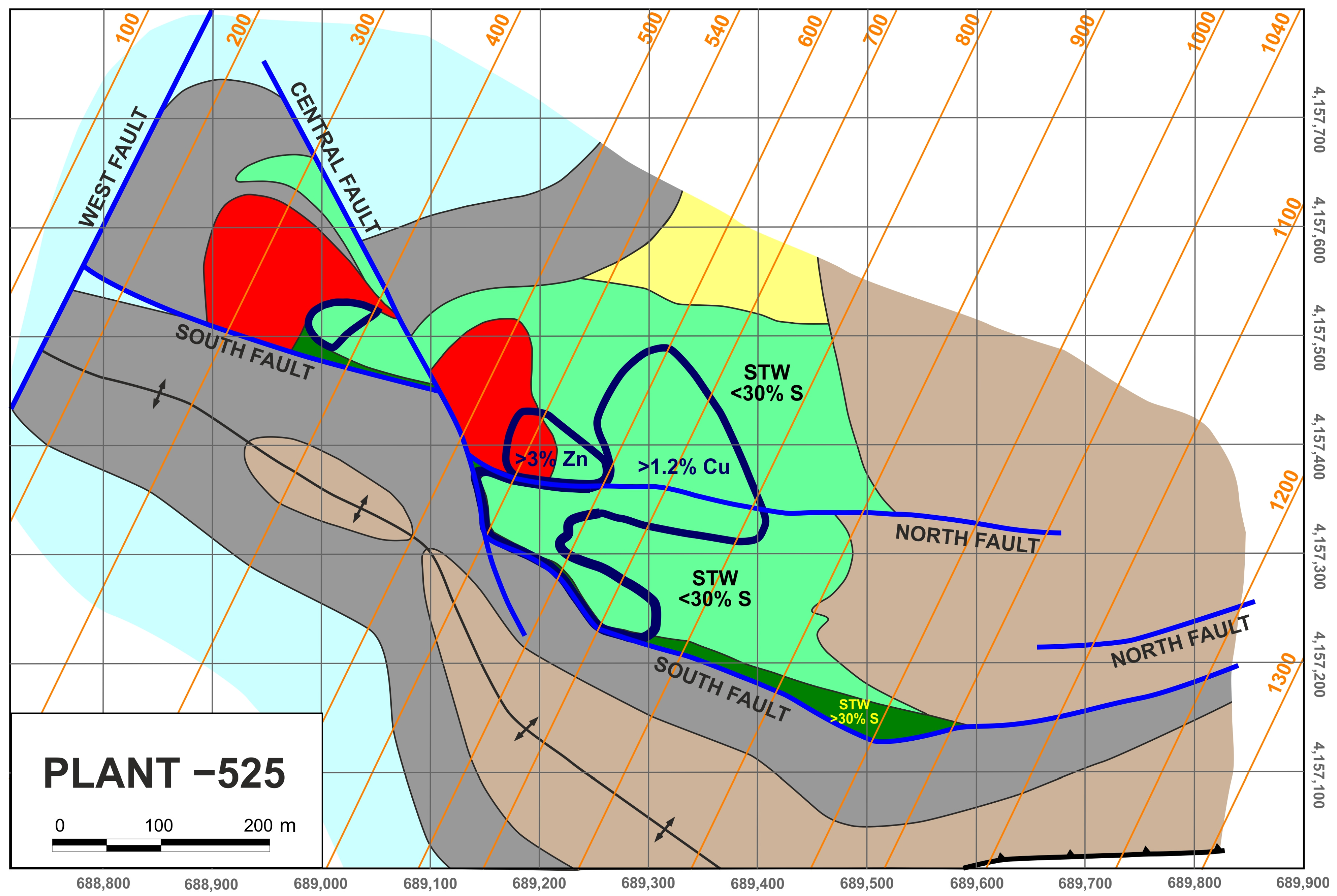
The structure of the Masa Valverde region is dominated by a major hectometer-scale listric fault, referred to as the South Fault, which strikes approximately N120°E and dips from steeply to gently to the NNE (Figure 6 and Figure 9). This fault offsets all the stratigraphic units exposed within the study area.
The beds in the hanging wall of the South Fault are folded into a large-scale, gentle anticline whose dimensions are comparable to those of the fault (Figure 6B). This anticline differs markedly from the other anticlines in the study area, because it is significantly more open, displaying a much larger interlimb angle, a lower structural relief, and a considerably greater wavelength.
Within the hanging wall of the South Fault, a subsidiary normal fault, dipping northward, occurs. This structure, referred to as the North Fault (Figure 9), branches from the upper steeply dipping segment of the South Fault, runs subparallel to the South Fault, and rejoins the lower gently dipping segment of the South Fault, defining a fault-bounded horse that is interpreted as part of a duplex structure. The localization of the duplex within the zone of greatest curvature of the main fault is mechanically consistent, as deformation in such regions cannot be efficiently accommodated by slip along a single fault surface, thereby favoring strain partitioning and the development of subsidiary splays.
Rhyodacitic rocks, together with the massive sulfide body and the associated stockwork, are confined to the hanging wall of the North–South Fault system and are absent in the South Fault footwall (Figure 6, Figure 9 and Figure 10). This distribution is consistent with the preferential generation of accommodation space within the hanging wall during volcanism and mineralization. Their close spatial association with the fault system suggests that both volcanic emplacement and hydrothermal mineralization were structurally controlled.
The black, green, and purple shales located on the southwestern limb of the large-scale gentle anticline developed within the hanging wall of the South Fault begin to thicken approximately 500 m from the fault, at the transition from the anticline hinge to its southwestern limb (Figure 6B). They progressively thicken toward the fault, reaching their maximum thickness immediately adjacent to the fault surface, where their thickness increases by up to 400% relative to that in the anticline hinge. In contrast, they maintain a relatively constant thickness on the northeastern limb of the anticline. Likewise, this stratigraphic unit maintains a relatively constant thickness both in the South Fault footwall and in the hanging wall away from the South Fault. The shales exhibit a wedge-shaped geometry adjacent to the South Fault (Figure 6B). If this geometry developed during sedimentation, the hanging wall area immediately adjacent to the South Fault would have represented the structurally lowest part of the basin relative to the anticline hinge, thereby providing the greatest accommodation space for sediment accumulation. In this scenario, the wedge-shaped geometry would also be compatible with the progressive fanning of individual beds expected in synkinematic growth strata, although the available data are insufficient to verify this pattern. In any case, the progressive and strongly asymmetric thickening of the unit, its restriction to the southwestern limb of the anticline onsetting approximately 500 m from the fault and reaching its maximum thickness immediately adjacent to the fault, and its wedge-shaped geometry are all consistent with the development of growth strata related to a synsedimentary fault. Alternatively, part of the observed thickening may reflect tectonic strain, as shale-dominated successions commonly undergo thickness changes during deformation. However, the approximately fourfold increase in thickness starting 500 m away from the fault combined with the relatively modest present-day reverse displacement of the South Fault (less than 100 m using the top of the shales as a reference surface) and the wedge-shaped geometry adjacent to the fault are difficult to reconcile with an origin solely by strain, suggesting that the observed geometry is more likely to preserve a significant synsedimentary component.
Several independent observations consistently support an extensional origin for the South–North Fault system. First, rhyodacitic rocks, together with the massive sulfide body and the associated stockwork, are confined to the fault system hanging wall. Likewise, the black, green, and purple shales display a marked thickness increase in the South Fault hanging wall. Together, these relationships indicate that accommodation space was preferentially generated within the hanging wall during volcanism and sedimentation. Considering the present-day sense of dip of the South and North Faults, this implies that their hanging walls originally represented the downthrown blocks, consistent with normal-fault kinematics. Second, the black, green, and purple shales thicken progressively toward the South Fault only along the fault-adjacent limb of the large-scale gentle anticline developed in its hanging wall, where they define a wedge-shaped geometry. This asymmetric thickening pattern is consistent with synextensional growth strata deposited on a rollover fold related to a listric normal fault. The large-scale gentle anticline differs markedly from the other anticlines in the study area, being considerably more open; its dimensions are comparable to those of the South Fault, and it is developed directly above its listric fault surface. These observations support a genetic relationship between both structures, so the anticline is interpreted as a rollover fold, and the South Fault is interpreted as an extensional growth fault. This interpretation is further supported by the normal displacement exhibited by the North Fault, whose geometrical relationship with the South Fault indicates that they define an extensional duplex.
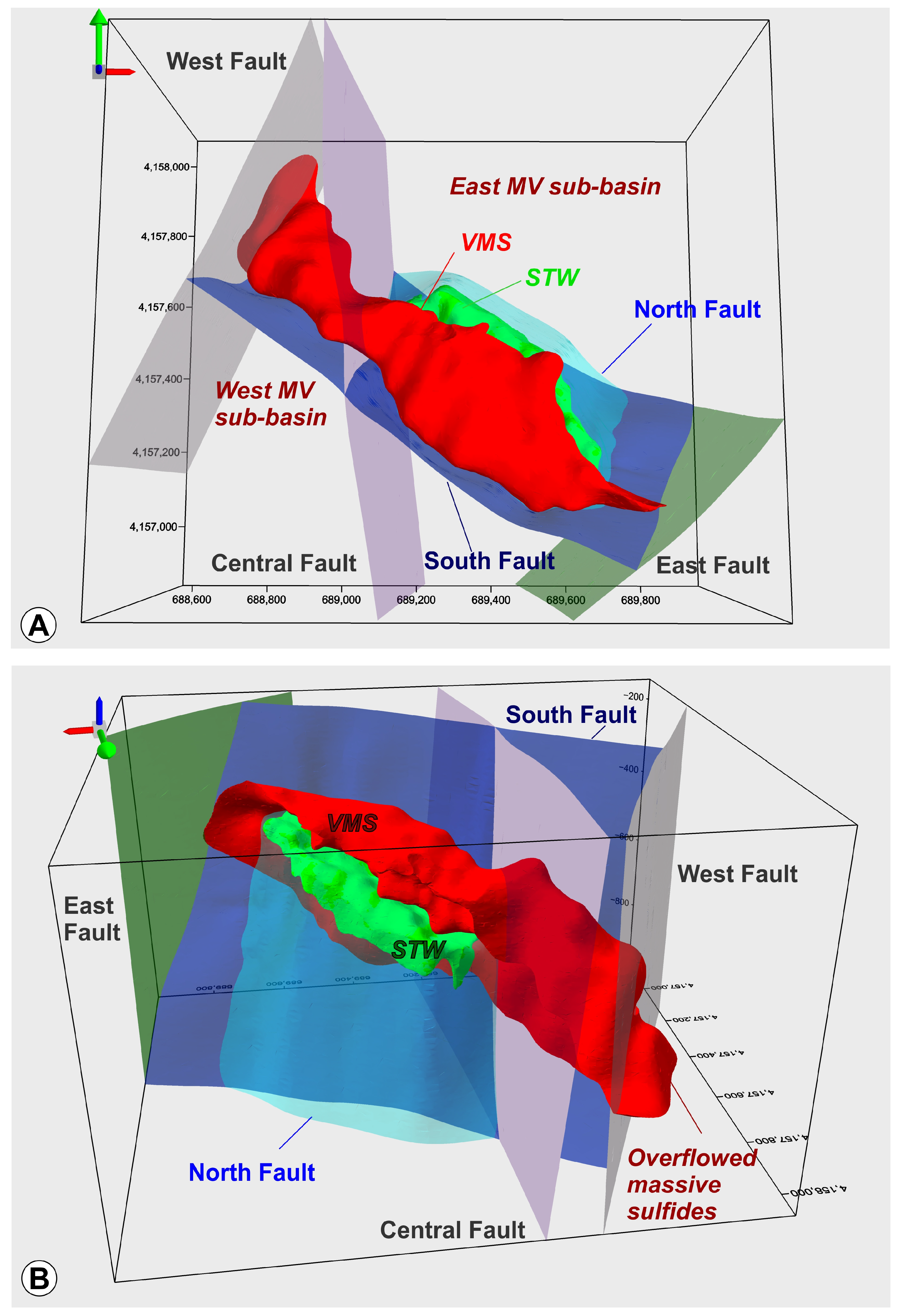
The basin is subdivided into two sectors by a subvertical NNW–SSE-trending structure referred to as the Central Fault (Figure 9, Figure 10 and Figure 11), comparable to the structural framework of the Río Tinto deposit, where the Eduardo Fault separates the Cerro Colorado and Corta Atalaya sectors [11]. In map view, the hectometer-scale Central Fault produces a dextral strike separation of the South Fault (Figure 9). More importantly, it marks an abrupt lateral transition between two distinct extensional structural domains. In the ENE block (East Masa Valverde sub-basin), the South and North faults constitute an extensional duplex that terminates against the Central Fault, whereas in the WSW block (West Masa Valverde sub-basin), the South Fault defines a simple half-graben lacking duplex development (Figure 12). This abrupt change in structural architecture across the Central Fault is consistent with lateral variations in the displacement of the extensional system, a role commonly at-tributed to transfer faults. An additional argument supporting this interpretation is pro-vided by the kinematics of the Central Fault. The maximum vertical thickness of the massive sulfide body is approximately 120 m (Figure 10B), and the orebody is present on both blocks of the Central Fault in map view (Figure 9). Therefore, the vertical component of displacement along the Central Fault cannot have exceeded this value; otherwise, the orebody would no longer appear on both sides of the fault in the map depicted in Figure 9. As a first-order geometric approximation, if the Central Fault had behaved as a purely dip–slip fault offsetting the South Fault, the maximum possible vertical displacement (120 m) would produce less than 45 m of dextral strike separation of the South Fault, based on its average dip of approximately 70° when the massive sulfide is involved (Figure 10). In contrast, the dextral strike separation of the South Fault observed in map view is approximately 150 m (Figure 9). This estimation demonstrates that the observed map separation cannot be explained by dip–slip displacement alone. Instead, it requires a substantial strike–slip component along the Central Fault, consistent with the kinematics expected for transfer faults. In addition, the concentration of the main orebody within the ENE block further indicates that the structural segmentation associated with the Central Fault exerted an important controlling effect on hydrothermal circulation and mineralization. Moreover, the angle between the strike of the Central Fault and that of the South and North Faults (approximately 45°) is also compatible with the spatial relationship commonly observed in oblique transfer faults. The combined geometric and kinematic consistency of these observations strongly supports interpreting the Central Fault as an extensional transfer fault.
The eastern and western limits of the basin are defined by two subvertical NE–SW-trending faults, referred to as the East Fault and West Fault, respectively (Figure 9, Figure 10 and Figure 11).
These hectometer-scale structures are interpreted as lateral basin-bounding faults that likely played a significant role in constraining the basin extent, and therefore controlling the mineralization distribution.
Assuming that the extensional interpretation presented above is correct, the present-day reverse displacement of the South Fault (Figure 6B) is interpreted as the result of subsequent contractional reactivation. In addition to the reverse displacement currently exhibited by the South Fault, several additional structures are consistent with a contractional overprint. One of these is an SSW-directed gently dipping thrust that displays significant reverse displacement (Figure 6 and Figure 10). This hectometer-scale structure, located in the South Fault footwall, branches from the gently dipping basal segment of the South Fault. In this scenario, strain partitioning was likely to occur, with fault motion being accommodated partly by reverse reactivation of the South Fault and predominantly by the development of a new thrust within its footwall, interpreted as a shortcut thrust. The formation of this shortcut thrust was probably mechanically controlled, because propagation along the trajectory defined by the pre-existing low-angle basal segment of the South Fault through the incompetent shale-dominated footwall represents a more favorable pathway.
The black, green, and purple shales located in the southwestern limb of the large anticline described above display, in the vicinity of the upper segment of the South Fault and above the extensional duplex, both gentle-to-moderate dips in the same direction as the southwestern limb of the regional anticline and dips in the opposite direction (Figure 6B). Notably, a substantial interval of shales immediately adjacent to the South Fault exhibits an opposite dip. This geometry is consistent with the bending of strata during displacement over non-planar fault surfaces, namely the upper segments of the North and South Faults. If this interpretation is correct, these folds might be interpreted as fault-bend folds developed during fault reactivation and suggest that not only the South Fault, but also the North Fault, was reactivated as a reverse fault.
As discussed above in relation to the thickness variation of the black, green, and purple shales in the region adjacent to the South Fault, these strata may have experienced strain. Part or all of this strain may have been acquired during the contractional event.
Moreover, a hectometer-scale open anticline, with dimensions comparable to those of the South Fault, occurs in its footwall (Figure 6 and Figure 10). Its northeastern limb is subparallel to the South Fault, and its axial trace is parallel to that of the South Fault (Figure 9). Where it can be constrained from the fold limbs, its axial surface is steep and approximately parallel to the upper segment of the South Fault; however, its dip cannot be deter-mined within the fold inner core because no stratigraphic marker horizons are available. The geometry, dimensions, and orientation of this structure are consistent with footwall buttressing, likely related to a mechanical contrast in rock competence between the two fault blocks. Thus, the South Fault footwall, where the anticline is developed, consists exclusively of incompetent shales, whereas the hanging wall also includes massive sulfide units.
In some sections, the South Fault exhibits a locally stepped geometry consisting of alternating steeply and moderately dipping segments, some of which reach lengths of up to approximately 100 m (Figure 10B). This geometry may reflect folding of the original fault surface during the contractional event. Such an interpretation is consistent with the possible development of buttressing adjacent to the South Fault. Nevertheless, the possibility that this fault geometry is inherited from the original normal-fault architecture, or that it results from the superposition of contractional deformation on a pre-existing extensional fault geometry, cannot be excluded.
All the present-day offset caused by the Central Fault (Figure 9) was not necessarily acquired entirely during the extensional stage. A subsequent reactivation during the con-tractional event cannot be excluded. Considering the orientation of the Central Fault and the contractional kinematics inferred from the newly formed and reactivated structures described above, dextral strike–slip reactivation of this steeply dipping fault is mechanically plausible. Such behavior is commonly observed during basin inversion, where pre-existing high-angle faults preferentially accommodate shortening by strike–slip and/or oblique–slip reactivation rather than by folding. Consequently, the present-day apparent dextral separation of the South Fault may record the superposition of synextensional transfer-fault displacement and subsequent contractional reactivation.
The overall structural architecture records evidence for both extensional and contractional deformation: the structural control exerted by the fault system on the distribution of rhyodacitic rocks and mineralization and on the thickness of the black/green/purple shales; the anticline developed above the South Fault is interpreted as a rollover fold and as a listric growth fault, respectively; the half-graben and the extensional duplex; and the inferred transfer and lateral basin-bounding faults collectively indicate an initial extensional event. In contrast, the reverse displacement currently exhibited by the South Fault, the footwall thrust is interpreted as a shortcut thrust, the folds interpreted as fault-bend folds that suggest reverse reactivation of the underlying fault system, the footwall anticline interpreted as a buttressing structure, the stepped geometry of the South Fault, and the Central Fault motion provide evidence for a subsequent contractional event. This event involved both buttressing and reactivation of pre-existing structures, as well as the development of new contractional structures, resulting in basin inversion. Comparable structural relationships involving buttressing and reverse reactivation of former normal faults during basin inversion have been described elsewhere, such as in the Jurassic rocks of the Asturian Basin, northwestern Iberian Peninsula [64].
The East Masa Valverde sub-basin measures approximately 750 m in length and 250 m in width at its central section, which contains approximately 90% of the substantial sulfide deposit (Figure 9 and Figure 11). The footwall of the sulfides displays prominent stockwork, primarily pyritic, with a maximum thickness of 120 m, developed in the rhyodacites (Figure 10). This stockwork shows significant levels of silicification and chloritization, also affecting rhyodacites.
This particular basin features an extensional duplex that is well-developed (Figure 9 and Figure 11). The basin’s shape is narrow and elongated, reaching a maximum depth of approximately 120 m due to the extensional movement along the South Fault. The fill is primarily composed of sulfides, predominantly pyrite. As previously indicated, the western boundary is defined by an NNW–SSE fault (Central Fault), while the eastern boundary is delineated by an NE–SW fault (East Fault).
The West Masa Valverde sub-basin measures approximately 350 m in length and 200 m in width at its maximum point. The extensional duplex is not present in this sector, and the South Fault is the one that controls the formation of this sub-basin (Figure 9 and Figure 11A,B). The maximum thickness of the sulfides is approximately 60 m. The footwall contains a predominantly pyritic stockwork that is up to 90 m thick and is developed in the rhyodacite. The volcanic rock is silicified and chloritized, though less intense than in the East Masa Valverde sub-basin. The eastern boundary of this sulfide massif (West MV sub-basin, Figure 11A) is the NNW–SSE fault (Central Fault), while the western boundary is the NE–SW trending fault (West Fault).
Outstandingly, to the western side of the West Fault, there is a 100-m-thick pyrite body with no associated stockwork, suggesting that the sulfides came from the West Sub-basin, and overflowed westward across the West Fault (Figure 11B). In addition to the geological 3D modeling of the deposit, the Cu, Pb, and Zn contents have also been modeled. This has resulted in the detection of enriched zones in these metals. The location of these zones is closely linked to areas of geological structures that, during tectonic inversion, can create open spaces and/or suffer buttressing processes, such as the South Fault (Figure 10B).
The geometry of these bodies is roughly ellipsoidal, with a core of copper-rich material and a gradual decline in content toward the external zone. It has been found that the stockwork exhibits enrichment in Cu, whereas the massive sulfides are mainly enriched in Zn and Pb (Figure 12A,B) by the buttressing process during the tectonic inversion. These new bodies cut across the S0 at angles ranging from 30 to 45 degrees.
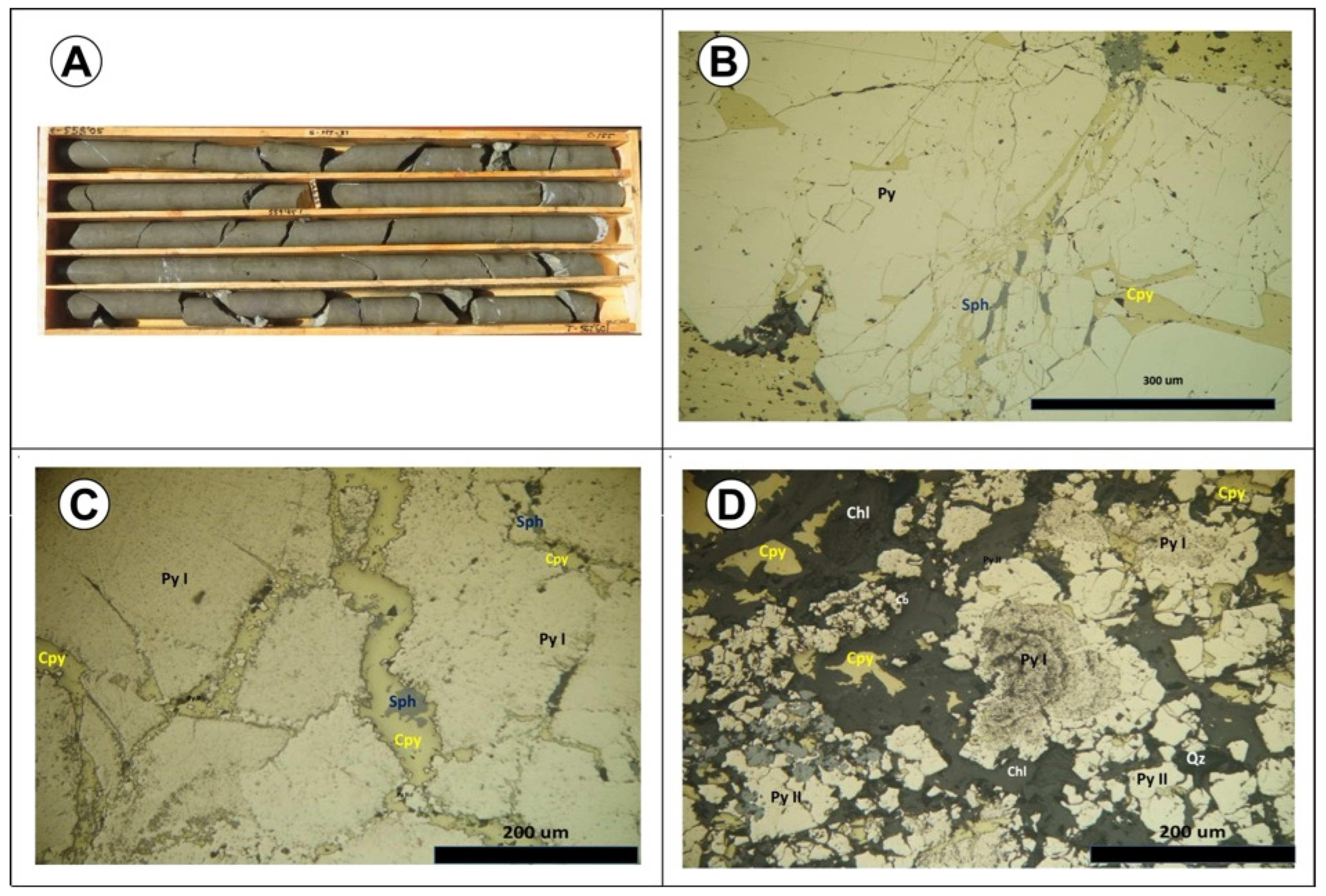
In the stockwork, brecciation and recrystallization took place during tectonic inversion, and a new paragenesis was formed, mainly comprising chalcopyrite, sphalerite, quartz, chlorite, and scarce carbonates. These minerals effectively cemented the breccias, partially replacing Py I and II and filling the open fractures (Figure 13 and Figure 14).
The new veins in the stockwork (Figure 13 and Figure 14) are centimeters up to a meter thick, filled by coarse grain chalcopyrite, along with minor amounts of quartz, pyrite, galena, sphalerite, chlorite, and carbonates, mainly siderite (for an explanation, see Section 5.1). The average Cu content ranges from 0.8% to 3%. These newly formed vein systems exhibit two preferred orientations, one vertical and one horizontal. In some areas, the composition of the breccia shows carbonate dissolution with sulfides that have a consistency similar to that of sand.
The recrystallization process during tectonic inversion in the massive sulfides results in the brecciation of Pyrite I, which is cemented by a new sulfide generation made up of abundant chalcopyrite, minor sphalerite and galena, and some sulfosalts of As and Sb (tetrahedrite and tennantite), together with some quartz, carbonates, phengite, and chlorite. This new sulfide generation is partially replacing the pyrites and filling the two systems of open fractures (Figure 8C,D, Figure 13 and Figure 14). The average content in metals is 0.6% Cu, 0.8% Pb, and 4%–5% Zn.
Several thin and polished sections from areas with higher metal grades have been studied from the stockwork and the massive sulfides (Figure 14).
The transition zone between the two mineralized areas (stockwork and VMS) contains a mixture of both ore types. However, it shows lower metal contents, with copper ranging from 0.8% to 1.2% and zinc between 3% and 4%.

5.2. Ore-Related Hydrothermal Carbonates

Hydrothermal carbonates are formed in two stages: firstly, during the stockwork development, and secondly, as a result of the buttressing effect caused by tectonic inversion. This inversion has an impact on both the stockwork, where the first carbonates are deposited, and the massive sulfides, which are overprinted by the new vein systems that have formed. The new sulfides (mainly chalcopyrite) and the new hydrothermal carbonates have cemented the breccias that have developed.
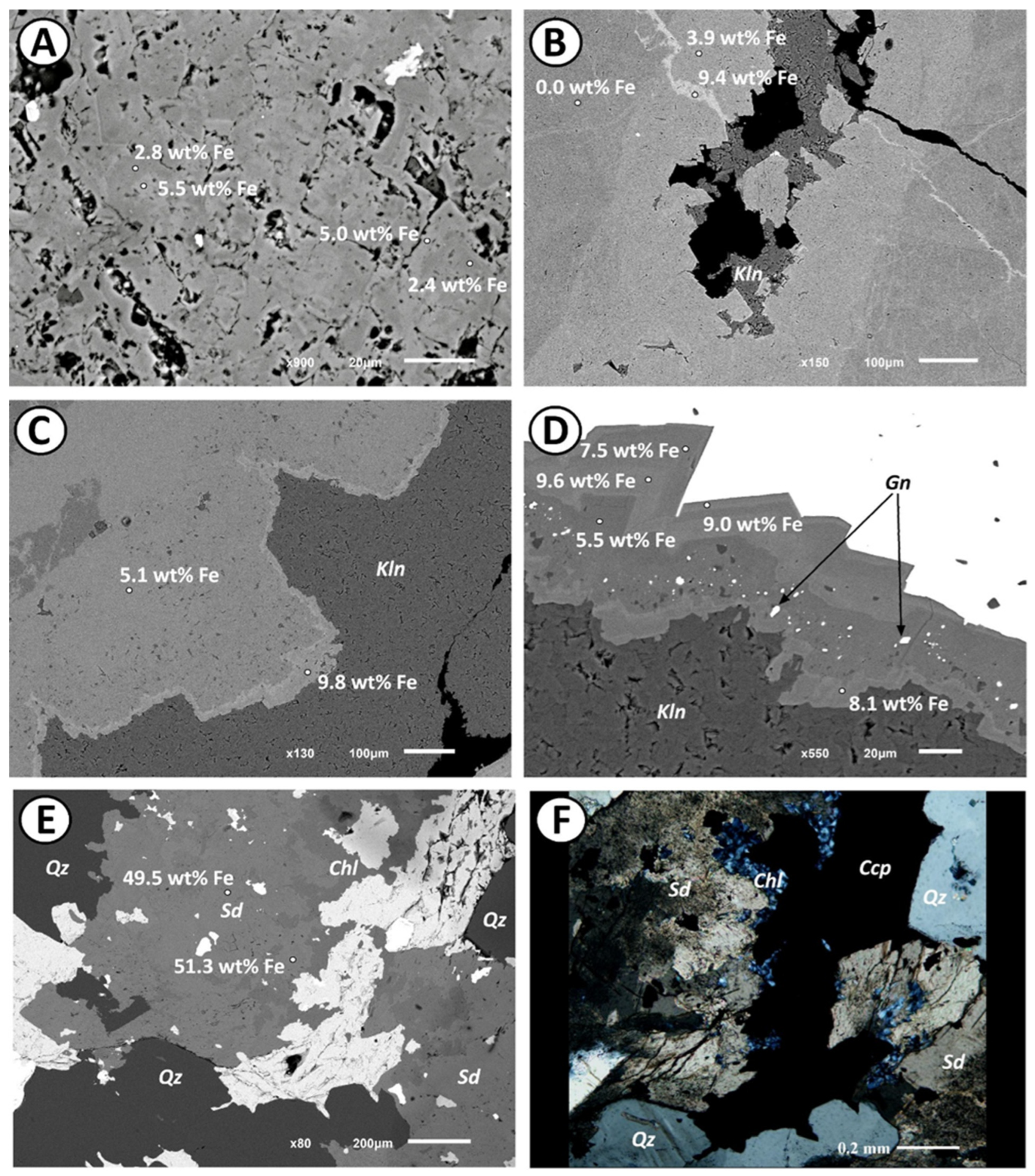
The mineralogical characterization of the hydrothermal carbonates allowed for the distinction of two main carbonate types, type 1 and type 2, based on textural and compositional criteria. Type 1 carbonate comprises turbid aggregates of fine-grained crystals (Figure 15A) that recrystallize in open spaces and around sulfides into clear, euhedral to subeuhedral, coarser-grained crystals (Figure 15B–D). In addition, some samples contain crosscutting veinlets filled by younger generations of type 1 carbonate (Figure 15B).
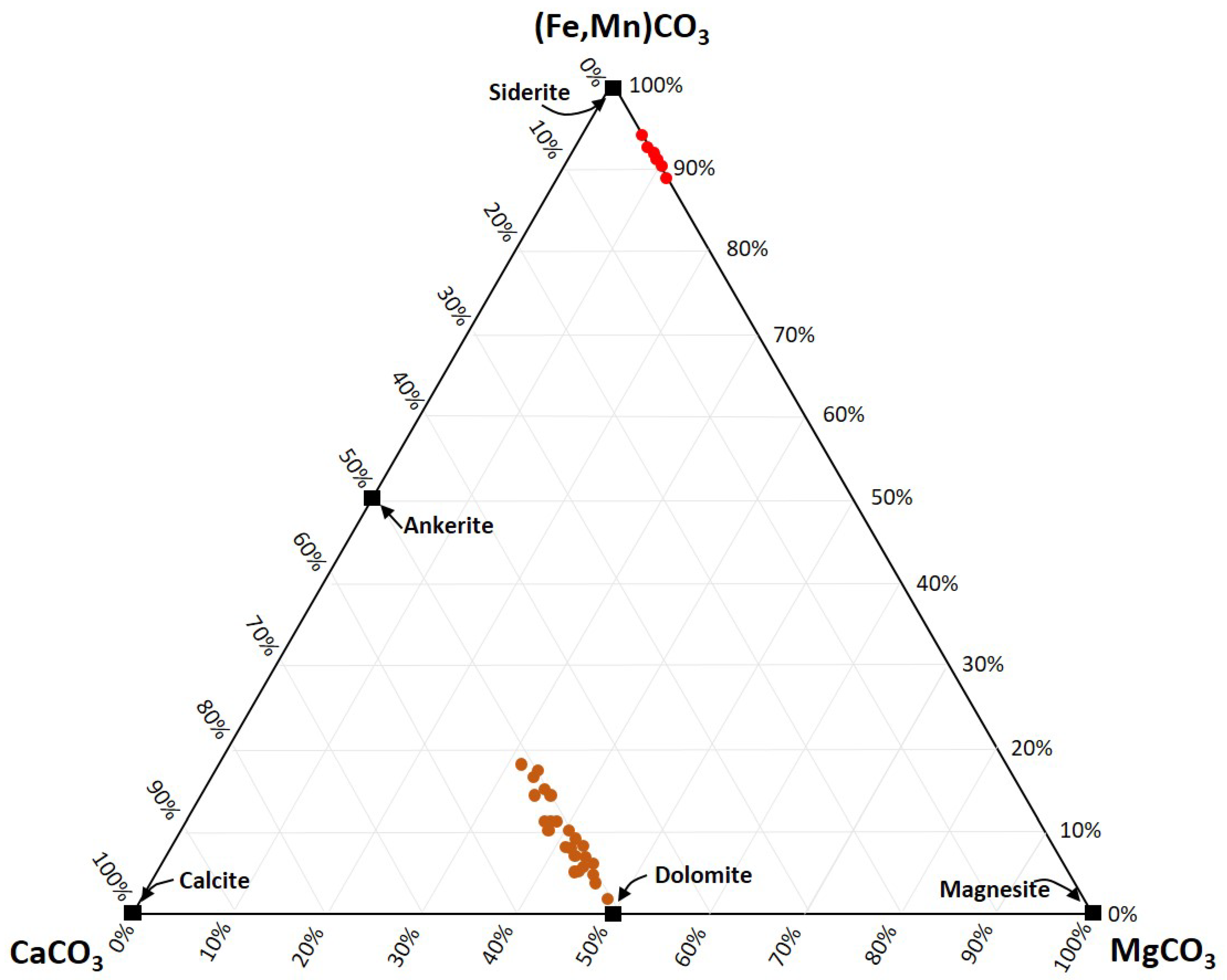
SEM-EDS analyses classify type 1 carbonate as dolomite, with compositions ranging between the dolomite and ankerite endmembers, but closer to dolomite (Figure 16). These hydrothermal carbonates display Fe/(Fe + Mg) ratios ranging from 0.0 to 0.3, with the most Fe-rich compositions corresponding to ferroan dolomite. Backscattered electron images of type 1 carbonates show crystals exhibiting compositional growth zoning (Figure 15A,C,D), where the latest growth stages are richer in iron (Figure 15C,D). Similarly, younger carbonate generations in the crosscutting veinlets are also enriched in iron (Figure 15B).
The sulfides associated with type 1 carbonate are mainly pyrite, sphalerite, galena, and tetrahedrite-(Zn), based on SEM-EDS semi-quantitative analyses, and minor arsenopyrite. These carbonates are associated with the development of the VMS stockwork.
Type 2 carbonates occur as aggregates of medium-grained, subeuhedral to anhedral crystals. SEM-EDS analyses indicate a more homogeneous chemical composition within individual crystals, corresponding to siderite with manganese contents up to 4 wt.% (Figure 16). Type 2 carbonate is associated with Fe-rich chlorite (XFe ≈ 0.8–0.9; EDS semi-quantitative), quartz, and sulfides (Figure 15E,F), with chalcopyrite being the most abundant sulfide. These carbonates are interpreted as being associated with the post-VMS stage, and they are related to the transpressional period of brecciation and copper enrichment.

6. Discussion and Conclusions

As observed in all VMS deposits of the IPB, the Masa Valverde structure is due to the transtensional regime resulting from the oblique collision during the Variscan Orogeny. In the Central Sector of the IPB, where Masa Valverde is located, half-graben basins are the most common structures [12].
The general structure of the Masa Valverde VMS mineralization resulted from two main periods of deformation. The first was largely transtensional; after the deposition of slates and quartzites of Upper Devonian (PQ formation, Figure 1B) in a stable continental shelf, localized extension and basin development took place, with associated volcanism and the development of VMS deposits during the Lower Carboniferous.
The second event was transpressional, producing reactivation of inherited structures and new ones during the Variscan Orogeny until the end of the Carboniferous, as a result of the oblique convergence of Gondwana and Laurussia.
Four evolutionary stages and two clearly differentiated structural periods can be distinguished (Figure 17A–D).

6.1. Lower Carboniferous Transtensional Period: Extensional Duplex Development

The 3D structural model suggests that the footwall volcanoclastic slates were deposited prior to the onset of extensional tectonics, indicating that sedimentation predated the main phase of basin development. The following transtensional regime led to the formation of an extensional duplex bounded by the South and North Faults (Figure 17A), highlighting the role of fault interaction in controlling the early structural characteristics of the Masa Valverde area.
This interpretation is consistent with the structural evolution recognized in many VMS deposits of the Iberian Pyrite Belt, where a Lower Carboniferous transtensional setting (ca. 360–345 Ma) [6] facilitated crustal extension and magma ascent. The development of the extensional duplex created favorable pathways for hydrothermal circulation and volcanic emplacement, thereby promoting the extrusion of rhyodacitic magmas during the initial transtensional stage (Figure 17A).
The massive VMS mineralizations, along with the stockwork and semi-massive stockwork, were formed and developed during the second stage (Figure 17B).
In the third transtensional stage (Figure 17C), black shales, volcanoclastic sediments, and gray shales were deposited. Sedimentation of the Culm greywackes began at the start of the compression stage.

6.2. Variscan Transpressional Period: Tectonic Inversion and Development of a New Vein-Type Mineralization

Following the extensional tectonic activity, there is a counterclockwise rotation of stress axes, which initiates a phase of compression [11,12]. In the case of the Masa Valverde, the majority of deformation during the transpression and inversion of normal faults is concentrated in the South Fault.
During the inversion, the sedimentary basin containing the VMS deposits was folded and the faults were reactivated, causing intense cataclastic deformation of the massive sulfides and stockwork, located on and around the South Fault (Figure 17D). There are successive stages of brecciation cemented by carbonates (siderite), sulfides (mainly chalcopyrite), and a minor presence of quartz.
During transpression, the pre-existing structures are reactivated and can locally generate open spaces (i.e., voids or zones of reduced pressure) despite the overall compressive environment. Several structures in Masa Valverde can generate open spaces and voids:
Flat segments of the North Fault can generate localized transtension leading to the formation of small extensional jogs.
A hinge zone of the anticlines that are formed during compression (saddle reef structures).
The surface of the South Fault is irregular and with bends (Figure 10B), which during tectonic inversion promotes the formation of open spaces and voids.
In the new open spaces created both by the inversion of the structures and by the effect of buttressing, another generation of sulfides precipitated, both in the stockwork and in the massive sulfide bodies, increasing the contents of metals, such as copper, lead, and zinc. These newly formed vein systems exhibit two preferred orientations, one vertical and the other horizontal, as has been described in the petrographic study (Figure 14B,D). The buttressing process leads to copper enrichment in the stockwork, while the massive sulfides become locally enriched in Pb and Zn.
Transpressional deformation played a key role in the remobilization and enrichment of pre-existing mineralization by generating open spaces that acted as pathways for hydrothermal fluid circulation and sulfide precipitation. This process led to the development of a new vein-type mineralization characterized by coarse-grained sulfides, mainly chalcopyrite, and significantly higher metal grades than those of the original stockwork and massive sulfide ores. In particular, Cu and Zn concentrations were enhanced by a factor of four to six, highlighting the economic importance of this late-stage mineralizing event.
The composition of the newly formed veins is strongly controlled by the nature of the host mineralization. Veins developed within stockwork zones are predominantly Cu-rich and dominated by chalcopyrite, whereas those emplaced within massive sulfide bodies display a polymetallic signature enriched in Zn and Pb. Transitional zones between these two mineralization styles contain mixed ore assemblages and intermediate metal grades, reflecting fluid interaction with both mineralized domains.
Furthermore, the systematic occurrence of Co-enriched chalcopyrite, with concentrations reaching up to 1% of Co content, suggests that transpressional fluid flow not only promoted metal remobilization, but also contributed to the redistribution and local concentration of critical metals.
The results and observations from the 3D model and petrographic studies indicate that deformation-related new veining constitutes an important mechanism for upgrading pre-existing VMS and stockwork mineralizations and generating economically significant Cu-, Zn-, Pb-, and Co-enriched ore zones.
The structural model proposed for Masa Valverde can be correlated with that of the La Zarza deposit [65] because it shares several features with it. La Zarza is located to the north of the Masa Valverde deposit, within the Northern Sector (Figure 1B and Figure 5), where pull-apart basins are particularly common. It was one of the largest pyrite producers in the Iberian Pyrite Belt (IPB), with approximately 45 Mt extracted for sulfur production [65,66].
The mineralized system [65] consists of volcanic-hosted massive sulfides, predominantly pyritic, with copper enrichment at the base and zinc–lead enrichment in the middle and upper parts. These sulfides overlie a feeder stockwork rooted in rhyodacitic volcanic rocks.
Additionally, areas with high silicification and polymetallic sulfide facies are present. These facies host mineralization enriched in Cu, Zn–Pb, and precious metals (Au and Ag), and occur in zones of intense deformation [66] that are associated with thrusts due to the inversion of earlier extensional structures.
The result was a complex geometry with flat and ramp features and southward vergence of the South Fault in La Zarza. In some cases, levels of mylonitized sulfides are present along these structures, possibly related to a buttressing effect similar to the Masa Valverde deposit.

Author Contributions

Conceptualization, M.A., F.C., D.A., P.G. and A.M.-I.; Methodology, M.A., J.-M.M., A.C., M.F., F.C., J.P., D.A. and A.M.-I.; Software, M.A., J.-M.M., A.C., M.F. and F.C.; Validation, M.A., J.-M.M., A.C., M.F. and F.C.; Formal analysis, A.C. and M.F.; Investigation, M.A., J.-M.M., A.C., M.F., F.C., J.P., D.A., P.G. and A.M.-I.; Resources, J.-M.M., A.C. and F.C.; Data curation, M.A., J.-M.M., A.C., M.F. and P.G.; Writing—original draft, M.A., J.-M.M., A.C., M.F., J.P. and D.A.; Writing—review & editing, M.A., J.P., P.G. and A.M.-I.; Visualization, M.A., J.-M.M., D.A. and P.G.; Supervision, M.A., J.P., P.G. and A.M.-I.; Project administration, D.A. and A.M.-I.; Funding acquisition, D.A. and A.M.-I. All authors have read and agreed to the published version of the manuscript.

Funding

This research received no external funding.

Data Availability Statement

The original data presented in the study are openly available in: https://atalayamining.com/es/operaciones/area-de-riotinto/proyecto-masa-valverde/ (accessed on 1 July 2026).

Conflicts of Interest

Mónica Arias is a consultant geologist and the proprietor of the company. She has never been employed as a consultant for any company associated with Masa Valverde. The paper reflects the views of the scientists and not the company, as she never received any funding or financial support from the company regarding Masa Valverde. Authors José-Manuel Macías and Fernando Cortes were employed by the company Atalaya Mining. The remaining authors declare that the research was conducted in the absence of any commercial or financial relationships that could be construed as a potential conflict of interest.

References

  1. Pinedo Vara, I. Piritas de Huelva; Summa: Madrid, Spain, 1963; p. 1003. [Google Scholar]
  2. Oliveira, J.T. The South Portuguese Zone: Stratigraphy and sedimentary tectonism. In Pre-Mesozoic Geology of Iberia; Dallmeyer, R.D., Martínez García, E., Eds.; Springer: Berlin/Heidelberg, Germany, 1990; pp. 334–347. [Google Scholar]
  3. Sáez, R.; Almodóvar, G.R.; Pascual, E. Geological constraints on massive sulphide genesis in the Iberian Pyrite Belt. Ore Geol. Rev. 1996, 11, 429–451. [Google Scholar] [CrossRef] [Scilit]
  4. Sáez, R.; González, F.; Donaire, T.; Toscano, M.; Yesares, L.; de Almodóvar, G.R.; Moreno, C. Updating Geological Information about the Metallogenesis of the Iberian Pyrite Belt. Minerals 2024, 14, 860. [Google Scholar] [CrossRef] [Scilit]
  5. Leistel, J.M.; Marcoux, E.; Thieblemont, D.; Quesada, C.; Sánchez, A.; Almodóvar, G.R.; Pascual, E.; Sáez, R. The volcanic hosted massive sulphide deposits of the Iberian Pyrite Belt. Review and preface to the special issue. Miner. Depos. 1998, 33, 2–30. [Google Scholar]
  6. Simancas, J.F.; Carbonell, R.; González Lodeiro, F.; Pérez Estaún, A.; Juhlin, C.; Ayarza, P.; Kashubin, A.; Azor, A.; Martínez Poyatos, D.J.; Almodóvar, G.R.; et al. Crustal structure of the transpressional Variscan orogen of SW Iberia: SW Iberia deep seismic reflection profile (IBERSEIS). Tectonics 2003, 22, 1062. [Google Scholar] [CrossRef] [Scilit]
  7. Mantero, E.M.; Alonso-Chaves, F.M.; Garcia-Navarro, E.; Azor, A.; Lisle, R.J. Tectonic Style and Structural Analysis of the Puebla de Guzman Antiform (Iberian Pyrite Belt, South Portuguese Zone, SW Spain). Geol. Soc. Lond. Spec. Publ. 2011, 349, 203–222. [Google Scholar] [CrossRef] [Scilit]
  8. Gumiel, P.; Sanderson, D.J.; Arias, M.; Roberts, S.; Martín-Izard, A. Analysis of the fractal clustering of ore deposits in the Spanish Iberian Pyrite Belt. Ore Geol. Rev. 2010, 38, 307–318. [Google Scholar] [CrossRef] [Scilit]
  9. Tucker, B.C.; Yuri, A.E.; Pascual, E. U–Pb geochronology of VMS mineralization in the Iberian Pyrite Belt. Miner. Depos. 2002, 37, 684–703. [Google Scholar] [CrossRef] [Scilit]
  10. Moreno, C.; González, F. Estratigrafía de la Zona Sudportuguesa. In Geología de España; Vera, J.A., Ed.; SGE-IGME: Madrid, Spain, 2004; pp. 201–205. [Google Scholar]
  11. Martin-Izard, A.; Arias, D.; Arias, M.; Gumiel, P.; Sanderson, D.J.; Castañon, C.; Lavandeira, A.; Sanchez, J. A new 3D geological model and interpretation of structural evo-lution of the world-class Rio Tinto VMS deposit, Iberian Pyrite Belt (Spain). Ore Geol. Rev. 2015, 71, 457–476. [Google Scholar] [CrossRef] [Scilit]
  12. Martin-Izard, A.; Arias, D.; Arias, M.; Gumiel, P.; Sanderson, D.J.; Castañon, C.; Sanchez, J. Ore deposit types and tectonic evolution of the Iberian Pyrite Belt: From transtensional basins and magmatism to transpression and inversion tectonics. Ore Geol. Rev. 2016, 79, 254–267. [Google Scholar] [CrossRef] [Scilit]
  13. Sanderson, D.J.; Marchini, D.R. Transpression. J. Struct. Geol. 1984, 6, 449–458. [Google Scholar] [CrossRef] [Scilit]
  14. Arias, M.; Gumiel, P.; Sanderson, D.J.; Martin-Izard, A. A multifractal simulation model for the distribution of VMS deposits in the Spanish segment of the Iberian Pyrite Belt. Comput. Geosci. 2011, 37, 1917–1927. [Google Scholar] [CrossRef] [Scilit]
  15. Williams, D. The geology of the Rio Tinto mines, Spain. Trans. Inst. Min. Metall. 1934, 43, 593–678. [Google Scholar]
  16. Carvalho, D.; Conde, L.; Hernández Enrile, J.; Oliveira, V.; Schermerhorn, L.J.G. Livro-guia das excursões geológicas na Faixa Piritosa Ibérica. III Reuniao de Geologia do Sudoeste do Maciço Hespérico da Península Ibérica, Huelva-Beja, 1975. Comun. Serv. Geol. Port. 1976, 60, 271–315. [Google Scholar]
  17. IGME. Síntesis Geológica de la Faja Pirítica del SO de España; IGME: Madrid, Spain, 1982; p. 106. [Google Scholar]
  18. Barriga, F.J.A.S. Metallogenesis in the Iberian Pyrite Belt. In Pre-Mesozoic Geology of Iberia; Dallmeyer, R.D., Martínez-García, E., Eds.; Springer: Berlin/Heidelberg, Germany, 1990; pp. 369–379. [Google Scholar]
  19. Leistel, J.M.; Bonijoly, D.; Braux, C.; Freyssinet, P.; Kosakevitch, A.; Leca, X.; Lescuyer, J.L.; Marcoux, E.; Milési, J.P.; Piantone, P.; et al. The Massive Sulphide Deposits of the South Iberian Pyrite Province: Geological Setting and Exploration Criteria; BRGM: Orléans, France, 1994; Volume 234, 236p. [Google Scholar]
  20. Tornos, F. Environment of formation and styles of volcanogenic massive sulfides: The Iberian Pyrite Belt. Ore Geol. Rev. 2006, 28, 259–307. [Google Scholar] [CrossRef] [Scilit]
  21. Leistel, J.M.; Marcoux, E.; Deschamps, Y.; Joubert, M. Antithetic behaviour of gold in the volcanogenic massive sulphide deposits of the Iberian Pyrite Belt. Miner. Depos. 1998, 33, 92–97. [Google Scholar]
  22. Rosa, D.R.N.; Finch, A.A.; Andersen, T.; Inverno, C.M.C. U–Pb geochronology and Hf isotope ratios of magmatic zircons from the Iberian Pyrite Belt. Mineral. Petrol. 2009, 95, 47–69. [Google Scholar]
  23. Marcoux, E. Lead isotope systematics of the giant massive sulphide deposits in the Iberian Pyrite Belt. Miner. Depos. 1998, 33, 45–58. [Google Scholar]
  24. Diagana, B. L’importance des Remobilisations des Métaux (Cu, Zn, Au) lors du Métamorphisme Rétrograde: Etude des Paléofluides et des Assemblages Minéralogiques des Amas Sulfurés Sud-Ibériques de Tharsis et La Zarza. Ph.D. Thesis, University Henri Poincare’ (Nancy I), Nancy, France, 2001; p. 308. [Google Scholar]
  25. Casado, G.; Martínez-Abad, I.; Arias, D.; Martín-Izard, A. Efecto contrafuerte en las mineralizaciones de sulfuros del entorno de la Falla Sur de Río Tinto. Geo-Temas 2016, 16, 463–466. [Google Scholar]
  26. Ruiz, C.; Arribas, A.; Arribas, A., Jr. Mineralogy and geochemistry of the Masa Valverde blind massive sulphide deposit, Iberian Pyrite Belt (Spain). Ore Geol. Rev. 2002, 19, 1–22. [Google Scholar] [CrossRef] [Scilit]
  27. Arias, M.; Nuñez, P.; Arias, D.; Gumiel, P.; Castañón, C.; Fuertes-Blanco, J.; Martin-Izard, A. 3D Geological Model of the Touro Cu Deposit, A World-Class Mafic-Siliciclastic VMS Deposit in the NW of the Iberian Peninsula. Minerals 2021, 11, 85. [Google Scholar] [CrossRef] [Scilit]
  28. Cambridge Mineral Resources Plc. Projects; Cambridge Mineral Resources Plc: London, UK, 2026; Available online: https://cambmin.co.uk/site/projects (accessed on 1 July 2026).
  29. Technical Report on the Mineral Resources Evaluation of the Masa Valverde Copper Project. Available online: https://atalayamining.com/es/operaciones/area-de-riotinto/proyecto-masa-valverde/ (accessed on 1 July 2026).
  30. Murphy, J.B.; Nance, R.D. A Supercontinent Model for the Contrasting Character of Late Proterozoic Orogenic Belts. Geol. 1991, 9, 469–472. [Google Scholar] [CrossRef]
  31. Silva, J.B.; Oliveira, J.T.; Ribeiro, A. Structural outline of the South Portuguese Zone. In Pre-Mesozoic Geology of Iberia; Dallmeyer, R.D., Martínez-García, E., Eds.; Springer: Berlin/Heidelberg, Germany, 1990; pp. 348–362. [Google Scholar]
  32. Schermerhörn, L.J.G. An outline stratigraphy of the Iberian Pyrite Belt. Bol. Geol. Min. 1971, 82, 239–268. [Google Scholar]
  33. Oliveira, J.T.; Matos, J.X. O camino de ferro da mina de São Domingos ao Pomarão: Um recurso geo-educacional na Faixa Piritosa Ibérica. In Proceedings of the XXIV Encontro de Professores de Geociências; Associação Portuguesa de Geólogos: Beja, Portugal, 2004; p. 19. [Google Scholar]
  34. Pereira, Z.; Matos, J.; Fernandes, P.; Oliveira, J.T. Devonian and Carboniferous palynostratigraphy of the South Portuguese Zone, Portugal—An overview. Comun. Geol. 2007, 94, 53–79. [Google Scholar]
  35. Soriano, C.; Martí, J. Facies analysis of volcano-sedimentary successions hosting massive sulphide deposits in the Iberian Pyrite Belt, Spain. Econ. Geol. 1999, 94, 867–882. [Google Scholar] [CrossRef] [Scilit]
  36. Routhier, P.; Aye, F.; Boyer, C.; Lécolle, M.; Molière, P.; Picot, P.; Roger, G. La ceinture Sud-Iberique à amas sulfurés dans sa partie espagnole médiane. Tableau géologique et métallogénique. Synthèse sur le type amas sulfurés volcano-sédimentaires. Mem. Du BRGM 1980, 94, 265. [Google Scholar]
  37. Carvalho, D.; Barriga, F.J.A.S.; Munhá, J. Bimodal siliciclastic systems—The case of the Iberian Pyrite Belt. In Volcanic-Associated Massive Sulphide Deposits: Processes and Examples in Modern and Ancient Settings; Barrie, C.T., Hanningtonm, N.D., Eds.; Reviews in Economic Geology; SEG: Littleton, CO, USA, 1999; Volume 8, pp. 375–408. [Google Scholar]
  38. Sáez, R.; Pascual, E.; Toscano, M.; Almodóvar, G.R. The Iberian Type of volcano-sedimentary massive sulphide deposits. Miner. Depos. 1999, 34, 549–570. [Google Scholar] [CrossRef] [Scilit]
  39. Nehlig, P.; Cassard, D.; Marcoux, E. Geometry and genesis of feeder zones of massive sulphide deposits: Constraints from the Río Tinto ore deposits (Spain). Miner. Depos. 1998, 33, 137–149. [Google Scholar] [CrossRef] [Scilit]
  40. Munhá, J. Metamorphic evolution of the South Portuguese/Pulo do Lobo Zone. In Pre-Mesozoic Geology of Iberia; Dallmeyer, R.D., Martínez-García, E., Eds.; Springer: Berlin/Heidelberg, Germany, 1990; pp. 363–368. [Google Scholar]
  41. Mitjavilla, J.; Martí, J.; Soriano, C. Magmatic evolution and tectonic setting of the Iberian Pyrite Belt volcanism. J. Petrol. 1997, 38, 727–755. [Google Scholar] [CrossRef]
  42. Rosa, C.J.P.; McPhie, J.; Relvas, J.M.R.S. Type of volcanoes hosting the massive sulfide deposits of the Iberian Pyrite Belt. J. Volcanol. Geotherm. Res. 2010, 194, 107–126. [Google Scholar] [CrossRef] [Scilit]
  43. Donnelly, K.E.; Goldstein, S.L.; Langmuir, C.H.; Spiegelman, M. Origin of enriched ocean ridge basalts and implications for mantle dynamics. Earth Planet. Sci. Lett. 2004, 226, 347–366. [Google Scholar] [CrossRef] [Scilit]
  44. Rosa, C.J.P.; McPhie, J.; Relvas, J.M.R.S.; Pereira, Z.; Oliveira, T.; Pacheco, N. Facies analysis and volcanic setting of the giant Neves Corvo massive sulfide deposit, Iberian Pyrite Belt, Portugal. Miner. Depos. 2008, 43, 449–466. [Google Scholar] [CrossRef] [Scilit]
  45. Munhá, J. Hercynian magmatism in the Iberian pyrite belt. Mem. Serv. Geol. Port. 1983, 29, 39–81. [Google Scholar]
  46. Strauss, G.K.; Gray, K.G. Base metal deposits in the Iberian Pyrite Belt. In Geology and Metallogeny of Copper Deposits; Friedrich, G.H., Genkin, A.D., Naldrett, A.J., Ridge, J.D., Sillitoe, R.H., Vokes, F.M., Eds.; Springer: Berlin/Heidelberg, Germany, 1986; pp. 304–324. [Google Scholar]
  47. Quesada, C. A reappraisal on the structure of the Spanish segment of the Iberian Pyrite Belt. Miner. Depos. 1998, 33, 31–44. [Google Scholar] [CrossRef] [Scilit]
  48. Houlding, S.W. 3D Geoscience Modeling-Computer Techniques for Geological Characterization; Springer: Berlin/Heidelberg, Germany, 1994; pp. 1–6. [Google Scholar]
  49. Lemon, A.M.; Jones, N.L. Building solid models from boreholes and user- defined cross-sections. Comput. Geosci. 2003, 29, 547–555. [Google Scholar] [CrossRef] [Scilit]
  50. Calcagno, P.; Courrioux, G.; Guillen, A.; Chiles, J.P. Geological modelling from field data and geological knowledge. Part I. modelling method coupling 3D potential field interpolation and geological rules. Phys. Earth Planet. Int. 2008, 171, 147–157. [Google Scholar]
  51. Kaufmann, O.; Martin, T. Reprint of “3D geological modelling from boreholes, cross-sections and geological maps, application over former natural gas storages in coal mines” [Comput. Geosci. 34 (2008) 278–290]. Comput. Geosci. 2009, 35, 70–82. [Google Scholar] [CrossRef] [Scilit]
  52. Maxelon, M.; Renard, P.; Courrioux, G.; Brandli, M.; Mancktelow, N. A workflow to facilitate three-dimensional geometrical modelling of complex poly-deformed geological units. Comput. Geosci. 2009, 35, 644–658. [Google Scholar] [CrossRef] [Scilit]
  53. Kampmann, T.C.; Stephens, M.B.; Weihed, P. 3D modelling and sheath folding at the Falun pyritic Zn-Pb-Cu-(Au-Ag) sulphide deposit and implications for exploration in a 1.9 Ga ore district, Fennoscandian Shield, Sweden. Miner. Depos. 2016, 51, 665–680. [Google Scholar] [CrossRef] [Scilit]
  54. Schetselaar, E.; Pehrsson, S.; Devine, C.; Lafrance, B.; White, D.; Malinowski, M. 3-D geologic modeling in the Flin Flon mining district, Trans-Hudson orogen, Canada: Evidence for polyphase imbrication of the Flin Flon-777-Callinan volcanogenic massive sulfide ore system. Econ. Geol. 2016, 111, 877–901. [Google Scholar] [CrossRef] [Scilit]
  55. Schetselaar, E.; Ames, D.; Grunsky, E. Integrated 3D Geological Modeling to Gain Insight in the Effects of Hydrothermal Alteration on Post-Ore Deformation Style and Strain Localization in the Flin Flon Volcanogenic Massive Sulfide Ore System. Minerals 2018, 8, 3. [Google Scholar] [CrossRef] [Scilit]
  56. Lajaunie, C.; Courrioux, G.; Manuel, L. Foliation fields and 3D cartography in geology: Principles of a method based on potential interpolation. Math. Geol. 1997, 29, 571–584. [Google Scholar] [CrossRef] [Scilit]
  57. McKinstry, H.E. Geología de Minas; Omega: Barcelona, Spain, 1970; 671p. [Google Scholar]
  58. Gumiel, P.; Arias, M.; Martín-Izard, A. 3D geological modelling of a polyphase deformed pre-Variscan IOCG mineralization located at the southeastern border of the Ossa Morena Zone, Iberian Massif (Spain). Geol. J. 2010, 45, 623–633. [Google Scholar] [CrossRef] [Scilit]
  59. Marjoribanks, R. Geological Methods in Mineral Exploration and Mining; Springer: Berlin/Heidelberg, Germany, 2010; 233p. [Google Scholar]
  60. Calcagno, P.; Martelet, G.; Gumiaux, C. Apport de la modélisation géométrique 3D a’l’interprétation géologique du complexe de Champtoceaux (massif armoricain). In Proceedings of the 19e’me RST Congress, Nantes, France, 9–12 April 2002; p. 79. [Google Scholar]
  61. Heiman, A.; Spry, P.G.; Teale, G.S.; Conor, C.H.; Wolfgangr Leyh, W.R. Geochemistry of Garnet-Rich Rocks in the Southern Curnamona Province, Australia, and Their Genetic Relationship to Broken Hill-Type Pb-Zn-Ag Mineralization. Econ. Geol. 2009, 104, 687–712. [Google Scholar] [CrossRef] [Scilit]
  62. Boissonnat, J.D. Shape reconstruction from planar cross-sections. Comput. Vis. Graph. Image Process. 1988, 44, 1–29. [Google Scholar] [CrossRef] [Scilit]
  63. Bertrand, P.; Dufour, J.F.; Francon, J.; Lienhardt, P. Modélisation Volumique à base Topologique; Actes MICAD: Paris, France, 1992; Volume 1, pp. 59–74. [Google Scholar]
  64. Uzkeda, H.; Bulnes, M.; Poblet, J.; García-Ramos, J.C.; Piñuela, L. Buttressing and reverse reactivation of a normal fault in the Jurassic rocks of the Asturian Basin, NW Iberian Peninsula. Tectonophysics 2013, 599, 117–134. [Google Scholar] [CrossRef] [Scilit]
  65. Strauss, G.K.; Roger, G.; Lecolle, M.; Lopera, E. Geochemical and geological study of the volcanosedimentary sulfide orebody of La Zarza, Huelva, Spain. Econ. Geol. 1981, 76, 1975–2000. [Google Scholar] [CrossRef] [Scilit]
  66. Strauss, G.K.; Beck, J.S. Gold mineralizations in the SW Iberian Pyrite Belt. Miner. Depos. 1990, 25, 237–245. [Google Scholar] [CrossRef] [Scilit]
Figure 2. Location of the 145 utilized boreholes from different surveys with the digital elevation model (DEM) of the area. Information provided by Atalaya Mining.
Minerals 16 00832 g002
Figure 3. Location of the 16 NE–SW cross-sections generated, based on the thorough study and relogging of the drill cores used for building the 3D model.
Minerals 16 00832 g003
Figure 4. Chart of the applied methodology for 3D model generation. (A) First step, (B) second step, and (C) third step.
Minerals 16 00832 g004
Figure 5. Geological map of the Northern Sector and Central Sector of the Spanish IPB. Modified from [12].
Minerals 16 00832 g005
Figure 6. (A) Detailed geological map of the Masa Valverde area. (B) Geological cross-section.
Minerals 16 00832 g006
Figure 7. Stratigraphic sequence defined in Masa Valverde deposit.
Minerals 16 00832 g007
Figure 8. (A) Rhyodacite with several generations of quartz (QI, QII, and QIII). (B) Colloform pyrite (Py I), containing small amounts of chalcopyrite, is characterized by concentric colloform banding. As can be seen in this photograph, a planar fabric is beginning to develop in the pyrites, particularly noticeable on the left side of the image. (C) Deformed black shale with chlorite and carbonate nodules oriented. Pyrite appears as inclusions within the carbonates, exhibiting the same orientation. (D) Detail of a carbonate nodule containing pyrite crystals, with pressure shadows in which quartz has crystallized. These nodules are embedded in an essentially chlorite matrix, with small quartz crystals.
Minerals 16 00832 g008
Figure 9. Horizontal section (Plant −525 m) showing the mineralized bodies (VMS and STW) and the structures that control the geometry of the Masa Valverde deposit. The colors are as shown in Figure 7.
Minerals 16 00832 g009
Figure 10. Vertical sections (300 and 600) of the Masa Valverde deposit. Please note that Section 300 (A) includes the South and Central Faults, while Section 600 (B) is characterized by the extensional duplex, which stands out as a particularly distinctive feature. The colors are as shown in Figure 7.
Minerals 16 00832 g010
Figure 11. (A) Zenithal view of the Masa Valverde deposit. The North Fault is partially transparent, allowing for the visibility of the copper stockwork in green, and massive sulfides in red. (B) North view of the Masa Valverde deposit (stockwork in green, and massive sulfides in red). The North Fault is partially transparent, allowing for the visibility of the copper stockwork. Please note that an extensional duplex is developed between the Central and East Faults. The colors are as shown in Figure 7.
Minerals 16 00832 g011
Figure 12. Bodies of Cu (in green) and Zn (in blue) enrichments within the stockwork and massive sulfides resulting from buttressing and tectonic inversion. (A) View from the NE showing that mineralized bodies are mainly located on the low-angle sectors of the North Fault. (B) Zenithal view showing that the mineralized bodies are concentrated primarily in the eastern sub-basin, where the extensional duplex is located.
Minerals 16 00832 g012
Figure 13. (A) Brecciated pyrite cemented by a new generation of sulfides, mainly chalcopyrite that filled fractures in the stockwork. (B) Pyrite vein I + II (Py) corresponding to the brecciated VMS stockwork formed during the tectonic inversion, accompanied by the crystallization of chalcopyrite (Cpy), sphalerite (Sph), and carbonates (Cb) as the main minerals. In the fracture zones, chalcopyrite partially replaces pyrite. (C) Massive sulfides containing Pyrite I brecciated. Idiomorphic to subidiomorphic Pyrite II crystals growing on Pyrite I in cavities that are later filled by chalcopyrite. (D) Massive sulfides containing Pyrite I that were brecciated during the tectonic inversion process, resulting in the formation of a chalcopyrite deposit that fills voids and fractures, and replaces the original pyrite (Py I), together with carbonate cement (siderite).
Minerals 16 00832 g013
Figure 14. (A) Drill core MJ81-4 (558.05–562.60 m) consists of massive sulfides, with no main deformation detected except for some minor fractures that cause partial brecciation in certain zones. (B) Microscopic examination reveals that pyrite is brecciated, forming an oriented microfracture system. These have been filled and cemented by chalcopyrite and sphalerite. (C) Upon closer inspection, it is evident that new pyrite generation has occurred, with chalcopyrite replacing pyrite I to a certain extent. (D) In some areas where the process of fracturing is more intense, there is often a presence of chalcopyrite, chlorite, carbonates, and quartz. In this case, the presence of both colloform pyrite I and sub-diomorphic pyrite II is clearly evident, with the latter growing on the former in a distinct, subidiomorphic pattern.
Minerals 16 00832 g014
Figure 15. BSE and optical microscopy images of ore-related hydrothermal carbonate and associated minerals. The iron content (EDS semi-quantitative) of the carbonates is shown. (A) BSE image of type 1 carbonate in an aggregate of fine-grained crystals showing compositional zoning. (B) BSE image of different generations of type 1 carbonates. Note a crosscutting veinlet with the highest iron content. (C) BSE image of type 1 carbonate growing toward an open space filled with kaolinite (Kln). Note the final, more Fe-rich growth band in the crystals. (D) BSE image of euhedral type 1 carbonate crystals surrounding galena (Gn). The crystals show compositional zoning, with an Fe-poor core containing tiny galena inclusions. (E) BSE image of type 2 carbonate, siderite (Sd). (F) Optical microscopy image of (E) under crossed polarizers, showing minerals associated with type 2 carbonate: quartz (Qz), chlorite (Chl), and abundant chalcopyrite (CCp).
Minerals 16 00832 g015
Figure 16. Ore-related hydrothermal carbonate plotting in the carbonate ternary diagram. Type 1: brown circles. Type 2: red circles.
Minerals 16 00832 g016
Figure 17. Conceptual diagram showing the four evolutionary stages that explain the genesis of the VMS mineralization at Masa Valverde, from an initial transtensional stage involving the development of an extensional duplex (AC), to a transpressive stage with compression and the inversion of the structures (D). The colors are as shown in Figure 7.
Minerals 16 00832 g017
Disclaimer/Publisher’s Note: The statements, opinions and data contained in all publications are solely those of the individual author(s) and contributor(s) and not of MDPI and/or the editor(s). MDPI and/or the editor(s) disclaim responsibility for any injury to people or property resulting from any ideas, methods, instructions or products referred to in the content.