


Abstract
The engineered artificial mineral (EnAM) concept aims to concentrate target elements in tailored mineral phases with defined composition, grain size, and shape through controlled slag chemistry and crystallisation. This study evaluates the transfer of LiAlO2 formation as a Li-bearing EnAM from a 5 kg laboratory-scale slag to a 125 kg pilot-scale slag. The pilot-scale slag was produced in a 300 L top-blown rotary converter and subjected to controlled cooling. A multiscale characterisation workflow combining micro-X-ray fluorescence (µXRF), X-ray computed tomography (XCT), SEM-EDX and electron backscatter diffraction (EBSD) was used to investigate EnAM distribution, morphology, intergrowth and grain structure. LiAlO2 was formed at pilot scale, with a phase fraction of 7.5–10.5 wt. % compared with 11.2–14.4 wt. % at laboratory scale. µXRF revealed substantially larger EnAM clusters at pilot scale, whereas EBSD showed that these clusters consist of finer, more irregular LiAlO2 grains. Nevertheless, both scales exhibited a comparable size-shape progression from smaller, compact clusters toward larger, less compact structures. XCT and SEM-EDX further revealed intergrowth of LiAlO2 with Mn-Al spinel. The results demonstrate the feasibility of transferring EnAM formation to pilot scale while showing that scale-up modifies EnAM yield, clustering, intergrowth, and individual grain properties.
1. Introduction
The concept of engineered artificial minerals (EnAM) treats a liquid metallurgical slag, which may contain valuable elements. The chemical composition within the molten slag is adopted to favour the crystallisation of selected species during cooling. These crystals enrich the target element in their lattice. The cooling process itself requires a defined temperature profile, which supports the selected solidification of the EnAM crystals. The EnAM concept reflects the tailoring of these crystals as well. It engineers their grain sizes and shape as well, since it requires less mechanical effort downstream to liberate and recover material from larger grains.
Lithium-ion battery (LIB) recycling generally combines mechanical, pyrometallurgical, and/or hydrometallurgical routes [1,2,3,4]. Martínez et al. [1] reviewed these LIB recycling pathways and compared how different companies implement the various process routes. Mechanical processing separates the battery into recyclable, relatively pure fractions [5,6], including lithium contained in the black mass fraction [7], which undergoes subsequent metallurgical treatment. In the hydrometallurgical recycling route, elements such as nickel (Ni), cobalt (Co), manganese (Mn), and lithium (Li) are selectively recovered through leaching and purification steps, but this route requires feed preparation, consumes chemical reagents, and generates waste liquids requiring further treatment. Pyrometallurgy offers robust treatment with relatively limited feed pretreatment and concentrates Co, Ni, and Cu into an alloy or matte. However, it requires high energy input, while Li and Mn partition into the slag and require additional processing for recovery [2].
The pyrometallurgical processing route of LIB recycling is getting increasing attention, yet recovering lithium from the resulting slag remains challenging [8,9]. Since slag is typically quenched, there is insufficient time for crystals to grow and a matrix with quite a large amorphous content form. Extracting valuable elements from the amorphous phase in the slag, in this case Li, is currently uneconomical, so the slag is usually discarded or used by the cement industry for construction purposes, or other further applications, such as insulation, fertilizer, polishing material, etc., which are considered downcycling application [2,10]. Element-wise recycling quotas will become effective in 2028 due to the European battery recycling regulation, and therefore the majority, i.e., 50% (80% from 2032 on) of the lithium has to be recovered and cannot be downcycled or dumped any longer with the slag. This motivates slag engineering through appropriate flux addition and controlled cooling to promote lithium-bearing crystalline phases suitable for downstream recovery. The Al2O3−CaO−SiO2−MnO−Li2O slag system investigated here is relevant to the pyrometallurgical recycling of LIB containing lithium nickel manganese cobalt oxide (NMC) cathodes. Aluminium-bearing battery components and additions of alumina, lime, and silica contribute to the slag composition [11]. The present synthetic system represents these principal oxide constituents under controlled compositional conditions.
Some studies have investigated the slag production optimisation by using pure components to produce synthetic slag [12,13,14,15,16]. These studies aim to investigate the crystallisation behaviour of the target mineral phase when changing flux composition and cooling rate. Further studies in the area of mechanical processing of EnAM-bearing slag systems aim to recover the crystals [17,18,19,20,21] containing the valuable elements from the slag. The success rate of the mechanical processing, which employs comminution and physical separation, depends on the initial properties of the slag, essentially of the yield, type, and size of the minerals that contain the target elements. As an example, the coarser the target mineral grains in the slag become, the higher the liberation chance during comminution and thus the higher the efficiency and recovery will be [22,23]. This could also mean that liberation is achieved at an earlier comminution stage, reducing the energy required for the mechanical process.
The tailored synthesis of lithium slag was earlier investigated by Elwert et al. [24]. By employing pure starting components, a well-defined Al2O3−CaO−Li2O−MgO−(MnO)−SiO2 slag system was developed, enabling the selective concentration of lithium into a lithium aluminate phase. Schirmer et al. [25] and Wittkowski et al. [26] investigated different lithium bearing species as possible target minerals in the lithium slag. These studies gave an insight into the feasibility of generating and processing the synthetic slag, most importantly the composition of the fluxes to be added in to the slag mixture. The composition has also been adjusted to correspond to that of the slag production using black mass from LIB recycling as feed material [27,28], where the weight percentage of manganese and lithium are relevant in this case. A review about the EnAM concept itself is explained in the study of Han et al. [29], where they also reported the possibility of applying the EnAM concept to additional slag systems, such as niobium-based, tantalum-based, copper-based, and steel-based slag systems.
The awareness of the EnAM concept and availability of designed slags allowed for studies on EnAM characterisation [30] and on downstream recovery processes, such as comminution, flotation, and mechanical separations [19,20,31,32]. These studies investigated the different slag production strategies and the processability of synthetic slags. In our previous study [30], two different cooling strategies were used, namely 25 °C/h and 50 °C/h, and the Li-bearing EnAM was formed at a lower cooling rate with preferable EnAM crystal size for further recovery processes. Although the previous study showed that significant difference on crystal size could be observed in the radial direction [18], from the centre part of the slag to the outer part of the slag sample due to the relative difference in cooling temperature rate, a slag can also have morphology variability along the height of the slag body. In addition, it was confirmed that the lower cooling temperature rate allows formation of bigger crystals. Based on that study, the scale-up slag in this study is produced using the lower cooling temperature rate procedure identified before.
Scaling up is essential to validate that the EnAM concept remains effective under industrially relevant heat and mass transfer, where thermal gradients, convection, and segregation can alter microstructure and liberation behaviour. In the scaled-up slag, we expect larger thermal gradient, slower average cooling, and potentially increased heterogeneity. Due to the increase in the slag sample size, the multi-scale characterisation workflow should be adapted, thus a new workflow is proposed in this study.
This study presents the comparison of the characteristics of the slags from a lab-scale trial, which was produced in 5 kg mass weight, and a pilot-scale trial in 125 kg produced mass weight. The lab-scale experiment from our previous study [30] will be referred to as Slag L, while the pilot scale slag done in this study will be referred to as Slag P. The objective is to investigate whether the EnAM concept developed at laboratory scale can be transferred to pilot-scale slag production while retaining the targeted formation of LiAlO2 and how scale-dependent solidification conditions affect its size, morphology, intergrowth, and spatial distribution.
2. Materials and Methods
2.1. Slag Production
The composition of the artificial slag developed in this study was derived from the chemical compositions reported in our previous study [30], where small-scale experiments demonstrated that the selected controlled cooling strategy was suitable to entirely crystallise slag rich in manganese and lithium oxides (see Table 1). Lithium aluminate (LiAlO2) was selected as the primary lithium-bearing EnAM because previous study demonstrated its enrichment from designed slags by flotation [12], providing an established basis for downstream physical separation. The present study builds on the lab-scale formation and characterisation of this target phase [30] to evaluate its transferability to pilot scale. The significant amounts of LiAlSiO4 and Li2MnSiO4 identified in the pilot slag (Table 2) show that lithium-bearing phase formation was not restricted to the intended target. Thus, the designation of LiAlO2 as the primary target leads to the process design. The focus of the characterization becomes more sophisticated and regards the intergrowth of the EnAM phase and its potential liberation in relation to grain size, while comparing the results with those previously obtained from the lab-scale slag (Slag L). Consequently, for the production of pilot-scale Slag P, the selected materials are also described in the referred article.
Table 1.
Feed composition of the pilot-scale slag.
Table 2.
Quantitative analysis of the mineral phases by XRD (in wt. %) of samples with different size fractions prepared from the middle section of pilot-scale slag P. Values show individual size fractions.
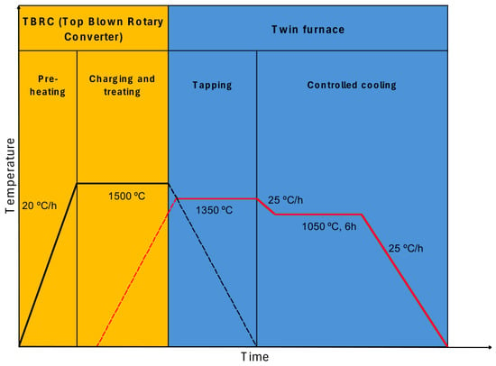
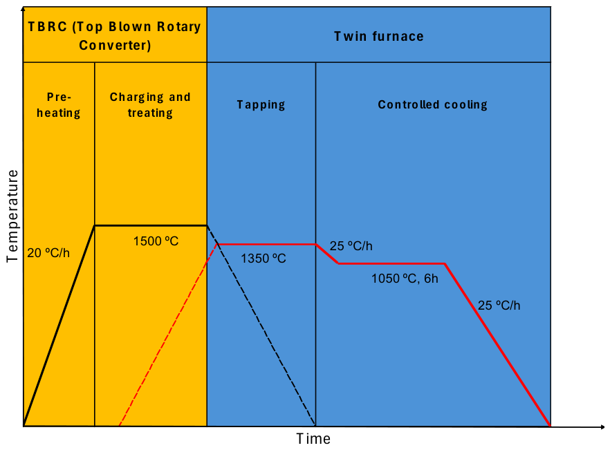
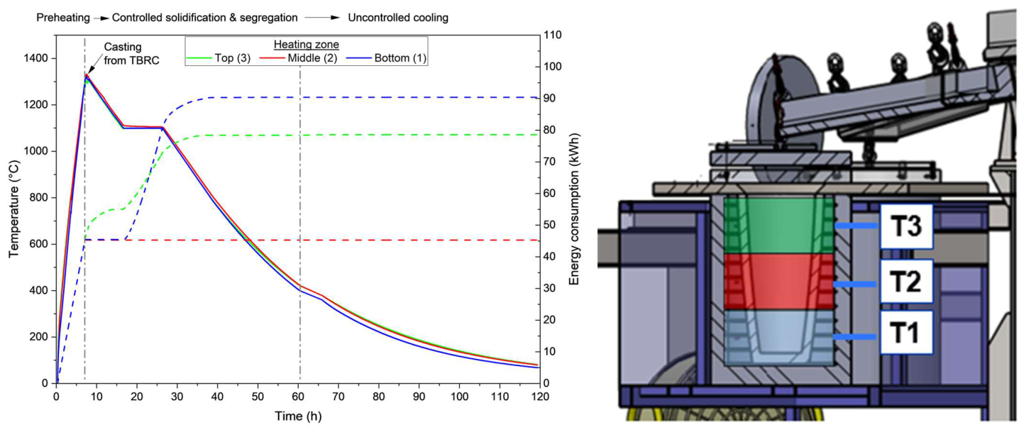
The experimental trials were carried out in a mid-size Top Blown Rotary Converter (TBRC) at the Institute of Metallurgy (IME), RWTH Aachen, with a 300 L vessel (100 L working volume), and the TBRC was equipped with a gas-oxyfuel burner. The details of furnace design, its dimension, and reactor configurations are presented in the study of Lucas et al. [11]. The temperature profile applied during the pilot-scale production is illustrated in Figure 1. Once the furnace heated up to 1500 °C, the charging procedure was initiated. After the compounds were completely added, the molten slag was maintained at around 1500 °C (± 20 °C) for full homogenisation of the liquid slag. Subsequently, the molten slag was directly cast into a clay-graphite crucible (type K600 from Aug. Gundlach KG, Großalmerode, Germany), which had been preheated to 1350 °C in an electric resistance furnace (Thermostar GmbH, Aachen, Germany) for the controlled cooling procedure. The casting procedure from TBRC at IME involves directing the molten synthetic slag through the open casting nose into the controlled cooling device. Afterwards, the slag was firstly cooled down to 1050 °C at 25 °C/h and held at this temperature for 6 h, following the procedure outlined in [30]. According to thermochemical simulations [12], the cooling procedure (e.g., holding temperature) at this temperature (1050 °C) promotes predominantly the solidification and is expected to enhance the grain size of lithium aluminate, as the preferred EnAM for this slag system, as well.
Figure 1.
Temperature profile of the pilot-scale slag production process, showing pre-heating and treatment in the top-blown rotary converter (TBRC), followed by tapping and controlled cooling in the twin furnace.
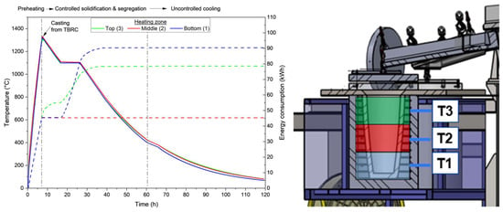
Figure 2 presents the recorded temperatures and energy consumption of the three furnace heating zones during preheating, casting, and cooling. Three thermocouples were positioned between the crucible and the twin-furnace vessel at the bottom (T1), middle (T2), and top (T3), as indicated in the schematic. The temperature profiles follow similar trajectories during controlled cooling. The comprehensive methodology and findings related to the thermochemical simulations performed for the slag, including assessments of viscosity and melting point and solidification process, are provided in the previous study [30].
Figure 2.
Recorded temperatures (solid lines) and energy consumption (dashed lines) of the bottom (T1), middle (T2), and top (T3) heating zones, with a schematic showing the thermocouple locations between the crucible and twin-furnace vessel.
The nominal feed composition of the pilot scale is presented in Table 1. Quantitative XRD measurements followed the same procedure described in our previous study [30], where information on the instrument, measurement conditions, and procedures were described in detail. Powder X-ray diffraction (XRD) patterns were achieved using a PANalytical Empyrean diffractometer (Malvern Panalytical, Almelo, The Netherlands), operated with a Co-tube at 35 kV and 35 mA. Samples were micronized using a McCrone mill (Retsch, Haan, Germany) to achieve a grain size below 10 µm. Powders were filled into 27 mm sample holders using the backloading technique. XRD patterns were recorded from 5 to 80° 2theta (step width 0.0131° 2theta) with a PIXcel 3D area detector, and total measurement time per sample was 2 h and 30 min. The irradiated area on the flat powder sample was kept constant at 15 mm × 12 mm by means of an automated divergence slit and respective beam mask. Phase identification was done using the ICDD PDF-5+ database, and quantitative data were obtained using the Profex/BGMN Rietveld software package (V 5.1.0). The software calculates an estimated standard deviation, which is based on the Rietveld refinement. Material from the middle section of the Slag P was jaw-crushed, milled, and sieved into nine particle-size fractions ranging from below 0.1 mm to 5 mm. The results are summarized in Table 2. LiAlO2 was identified in every fraction, with contents ranging from 7.5 to 10.5 wt.%. Eucryptite and lithium manganese silicate were also present in all fractions, demonstrating that lithium-bearing phase formation was not restricted to the targeted aluminate phase.
The chemical formula given below is a general chemical formula based on the reference use in XRD without considering potential impurities. The feed contains 8.5 wt. % Li2O, equivalent to approximately 3.95 wt. % elemental Li. The lithium concentrations could be estimated using ideal stoichiometric compositions, but a bulk estimate would additionally require the mass proportions of the analysed fractions. Moreover, the present characterisation workflow does not directly determine lithium concentrations or quantify lithium potentially incorporated into other phases as an impurity or through substitution. The nominal feed composition also does not establish the total lithium concentration in the final slag. Therefore, a complete lithium mass balance cannot be determined from the available data.
2.2. Sample Preparation
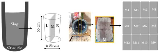
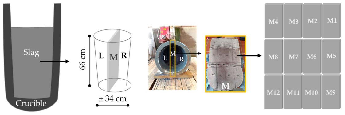
Figure 3 shows the dimension of the slag body and the first step of the sample preparation procedure. The initial slag body was cut at the company Steinrestaurierung Tobias Neubert (Halsbrücke, Germany) using a diamond saw (80 cm blade diameter, 5 mm thickness). Two initial cuts were applied to split the initial slag along the main axis into three parts, into left (L), middle (M), and right (R) blocks, where the middle block is 5 cm thick. The three cut blocks showed that there were already two major horizontal cracks that split the slag blocks into 3 sections. Subsequent cuts resulted in smaller blocks with approximately 30 cm length and 9 cm width (Figure 3). This created 24 pieces of slag block from both the left and the right parts, as well as 12 pieces from the middle part. The crucible was able to be detached easily from the slag body. Each of the pieces was named numerically to take into account its position within the slag body during analysis. The sample blocks were named M1 to M12 (M for the middle part sample), as illustrated in Figure 3.
Figure 3.
Schematic representation of the slag and the crucible, followed by the cutting scheme of the slag and the slag blocks produced, named M1 to M12.
2.3. Characterisation Method
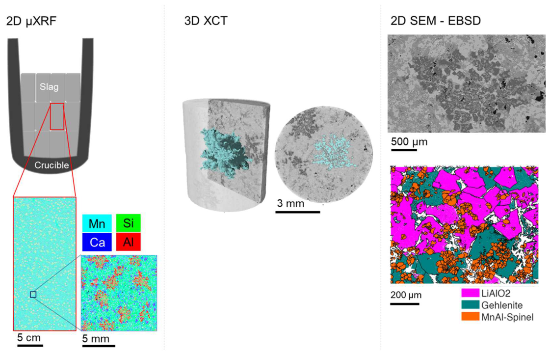
Selected slag blocks were characterised using complementary analytical methods to quantify the properties of the lithium aluminate (LiAlO2) as the EnAM. Throughout this study, the term EnAM cluster refers to a spatially connected LiAlO2-rich region that may contain multiple LiAlO2 grains and intergrown phases, whereas EnAM grain refers specifically to an individual LiAlO2 crystal resolved by crystallographic grain boundaries. Accordingly, µXRF is used to identify and quantify EnAM-rich clusters at the macroscopic surface scale, XCT resolves the three-dimensional morphology of these clusters, SEM-EDX reveals their internal phase intergrowth, and EBSD resolves individual LiAlO2 grains and their crystallographic boundaries.
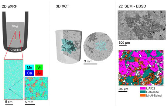
The characterisation workflow, shown in Figure 4, was adapted to pilot-scale slag samples. The characterisation of the sample began with analysing the macroscopic heterogeneity, i.e., the species distribution, at the surface of the slag blocks using micro-X-ray fluorescence (µXRF). Once the heterogeneity, the presence of relevant species, respectively, was observed, several areas of interest were chosen to be taken as drill cylinder samples for the X-ray computed tomography (ZEISS Xradia 510 Versa, Carl Zeiss, Oberkochen, Germany)) measurement to get the 3D microstructure information on the sample. The µXRF and the XCT workflow follows the characterisation methods done in the previous study [30]. Additional higher-resolution imaging of slag textures and phases was performed by scanning electron microscope (SEM). To evaluate crystallinity, electron backscatter diffraction (EBSD) was used to determine grain boundaries and grain sizes of the phase of interest.
Figure 4.
Characterisation workflow starting with micro-X-ray fluorescence (µXRF) element mapping on the slag’s flat surface, followed by 3D XCT for the morphological analysis and detailed analysis of the EnAM grain size and grain boundaries from 2D SEM and EBSD.
2.3.1. Micro-X-Ray Fluorescence (µXRF)
Micro-X-ray fluorescence (µXRF) measurement was performed to obtain an overview of the slag using an M4 Tornado (Bruker Nano GmbH, Berlin, Germany). The measurement provides composition and visualisation of elemental distribution [33]. The µXRF measurement needs to be performed on a horizontal plane, and the surface plane needs to be flat. Therefore, the cut sample blocks are suited to be directly used in this measurement. This poses as an advantage of the µXRF analysis since only minimal sample preparation is required, and it is not destructive for the sample.
Four slag blocks (M2, M5, M6, and M10), representing different vertical and radial positions within the solidified slag body, were analysed by µXRF. A radially homogeneous distribution was initially assumed for the sampling strategy. However, because only selected positions were investigated, this assumption could not be conclusively validated for the entire slag body. The µXRF results will be revealed at the investigated positions in the later section. The measurements were conducted using a rhodium (Rh) source and the two spectrometers as the detectors. An accelerating voltage of 50 kV and 600 µA was used. The distance between the individual measurement points was 150 µm, and the exposure time was 30 ms. This low-resolution acquisition has the advantage of providing a whole overview while keeping an efficient measurement time. To get a better resolution, a smaller area with a measurement point distance of 25 µm and an exposure time of 20 ms was used. The element maps were produced for aluminium (Al), calcium (Ca), manganese (Mn), silica (Si), and the overlay of all four elements. The detection of only aluminium (Al) in the element map indicates the presence of lithium aluminate (LiAlO2) as the target phase [30]. The measured area and number of analysed objects from µXRF are presented in Table 3. Here, an object means a segmented EnAM cluster.
Table 3.
Field of view for µXRF measurement. The samples M2, M5, M6, and M10 belong to pilot-scale Slag P; lab-scale Slag L is included for the comparison.
The Al and multi-element overlay maps were processed using ImageJ 1.53t (FIJI) [34]. Images were first converted into 8-bit images then filtered for smoothing using a Kuwahara filter with a sampling window value of 7. The image binarization was conducted using Auto Threshold choosing the method Yen, followed by morphological closing and opening to remove noise. Regions of interest (ROI) were defined by excluding objects in the sample border. In each binarised image, EnAM clusters were defined as discrete regions of connected foreground pixels representing the segmented EnAM phase. Pixels were assigned to the same particle when they were connected through their edges or corners, corresponding to eight-neighbour connectivity. Objects smaller than 8 pixels were classified as segmentation noise and excluded from the analysis. Particles intersecting the image boundary were excluded because their complete geometry could not be determined. Touching particles that remained connected after binarisation were treated as a single object. For each identified particle, the centroid coordinates (X and Y), projected area, and circularity were extracted using particle analysis. Distance between objects was quantified as the 2D centroid-to-centroid nearest-neighbour distance (NND). The centroid coordinates from the image data were used to compute the NND by using Python 3 k-dimensional tree (kd-tree) [35].
2.3.2. X-Ray Computed Tomography
A drill cylinder sample with a diameter of 6 mm was extracted from block M6 and was analysed by using XCT. Block M6 was selected for detailed XCT investigation because its µXRF-derived EnAM-cluster size distribution was comparable to those of the other investigated blocks. This provided a basis for examining its local three-dimensional structure but did not establish statistical representativeness for the entire slag body. The acquisition parameters were set the same as the previous study [30]. Afterwards, a reconstruction procedure using a filter back projection with software XMReconstructor (version 11.1.8043) was done to get the image stacks out of the projection images. The aim of this measurement was to obtain a 3D overview of the size and shape of the EnAM clusters in the slag.
Following the reconstruction, image processing steps are carried out to extract the information on the objects. For this purpose, ImageJ (FIJI), Ilastik (version 1.4.0), ORS Dragonfly (v.2022.1., Objects Research Systems, Montréal, QC, Canada), and VGSTUDIO MAX (version 3.3) were used. First, Unsharp Mask was used to sharpen, and Gaussian filter in ImageJ was used to smooth the image. The segmentation was done using Ilastik software. The object analysis and visualisation were done using VGSTUDIO MAX.
Following the segmentation of the phases of interest, they were analysed to account for isotropic behaviour using anisotropy analysis in VGSTUDIO MAX. This analysis uses the mean intercept length (MIL) method, where thevnumber of intersections between a linear grid and the object interface is counted as a function of the 3D orientation. Anisotropy is well explained in the study of Odgaard [36]. The degree of anisotropy is determined by the radii of an ellipsoid that fits a point cloud after calculating MIL vectors. The degree of anisotropy (DA) is calculated as follows:
where and are the min and max lengths of the radii of the ellipsoid fitted on the MIL points, respectively.
For each individual object, the anisotropy was computed to characterise directional dependencies in the 3D structure. Prior to anisotropy estimation, the number of angles was set to 2000, and the number of lines along each angle (y/z) was set to 100/100. The defined numbers of angles and lines stayed constant across all objects to ensure comparability.
2.3.3. Scanning Electron Microscopy (SEM)
Samples were prepared in epoxy mount with a diameter of 25 mm and polished for the SEM imaging. The SEM measurement was performed using the XL 30 environmental scanning electron microscope (ESEM-FEG, FEI Europe B.V., Eindhoven, The Netherlands). BSE images of the grain mounts along with EDX-spectra were generated from the measurement.
2.3.4. Electron Back Scattered Diffraction (EBSD)
A Zeiss Gemini 450 SEM coupled with an EBSD detector (Oxford Instruments, Buckinghamshire, United Kingdom) was used for this study. This EBSD detector captures the diffracted electrons when the electron beam strikes the sample. The diffracted electrons form lines, which correspond to the lattice planes of the crystal lattice. After EBSD pattern collection, this phase indexing was done by detecting the Kikuchi bands and matching the experimental patterns to simulated patterns from the known crystal structures to determine the phase and orientation [37]. The crystal phase indexes used for the samples were lithium aluminate, gehlenite, and Mn-Al spinel. EBSD analysis gives information on the grain orientation and grain boundaries of the phases of interests.
Samples used for SEM measurement were further polished on the surface to get a good quality on the EBSD measurement. The analysed sample area is approximately 28.3 mm2 for the lab-scale Slag L and 6.7 mm2 for the pilot-scale Slag P, respectively, comprising 136 and 565 analysed objects, in this case, EnAM grains. These measurements characterize the grain structure within the examined area; the number of grains does not constitute independent spatial replication across the slag body. To process the data, an open source MATLAB toolbox called MTEX (version 5.10.2) [38] is used. This toolbox allows the analysis of crystallographic data produced by EBSD measurement. To be able to process the data correctly, the orientations need to be defined correctly during the data import, since the direction of the sample, the detector, and the stage during measurement need to be justified. Afterwards, the grain orientation can also be seen relative to the reference crystal orientation. Thus, distinguishing between grains based on their crystallographic orientation is possible. Subsequently, misorientation of more than 6° is determined as the grain boundaries.
3. Results and Discussion
3.1. Heterogeneity of the Slag from µXRF Analysis
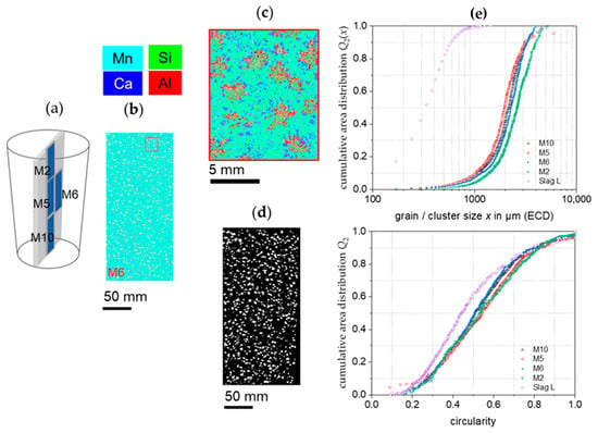
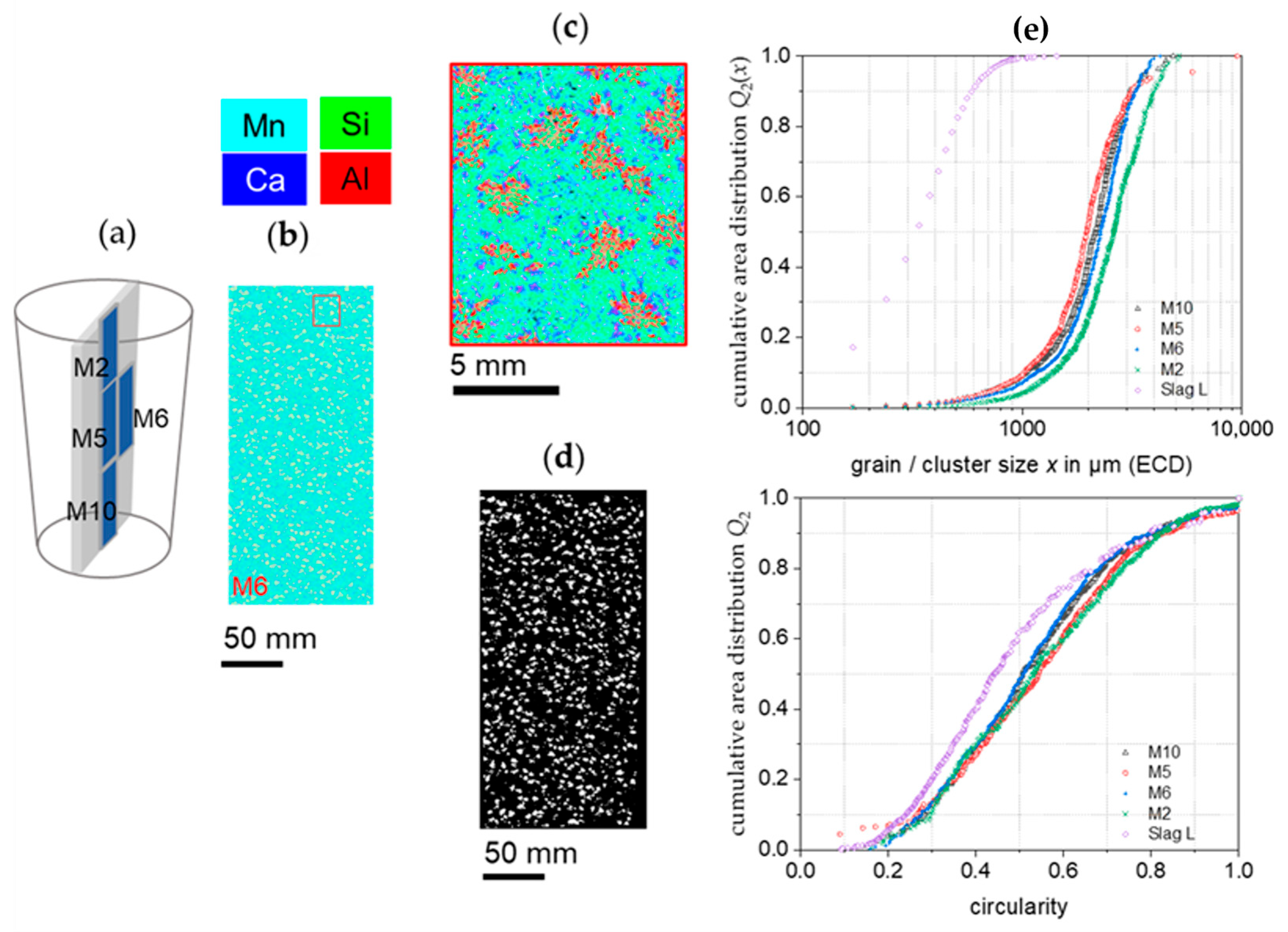
The µXRF element maps (M6) and the corresponding slag positions (M2, M5, M6, M10) from Slag P are presented in the Figure 5a–c. The combination of the element maps for the elements Al, Si, Mn, and Ca was used to determine the overall EnAM distribution within the field of view. From a qualitative point of view, here false coloured red-yellow grains within the turquoise matrix are present in the sample. The higher resolution (Figure 5c) of the µXRF surface mapping shows that the red-yellow grains are a cluster of the EnAM with other mineral phases, as already discussed in [31]. Each cluster was treated as an individual object. To get the size distribution of the cluster, the µXRF element maps with the low resolution were segmented for all samples. The example of µXRF element maps is shown in Figure 5b. They were binarized to the image of segmented EnAM clusters Figure 5d. The segmentation process was also done to the µXRF map of the lab-scale slag (Slag L). For clarity, the µXRF results from the Slag L study [31] are shown in the appendix (Figure A1).
Figure 5.
Overview of the slag surface with µXRF: (a) surface position for µXRF position, (b) the overlay of all element maps for Mn, Si, Ca, and Al with a pixel size of 150 µm, followed by (c) element map with pixel size of 25 µm showing detailed view of the red rectangle area in (b), (d) segmented object as the EnAM cluster from (b), and (e) the size and shape distribution of the EnAM cluster from different position.
It further shows a similarly uniform distribution of the clusters across the radius and along the vertical profile, as well as the comparison with the lab-scale slag. The cluster shape is also quantified and compared between Slag P and Slag L.
Each plot of the cluster size distribution Figure 5e originated from the corresponding cut blocks of the original Slag P; the data allows quantification of the influence of the sample position on the cluster formation. The overall spread in the median of the cluster size amounts to less than 2, with sample M5 (core) having the smallest value of x50,2 = 1900 µm and M2 (top) having the largest value of x50,2 = 2600 µm. The x50,2 values of the other blocks are in the range of 1900–2100 µm. This gives the average x50,2 value of 2250 µm for the across the investigated sections of slag sample P. The shape of the clusters, however, does not show significant difference. The shape of the cluster seems to be homogenous based on its circularity. When comparing the whole slag structure of Slag P and Slag L, it is obvious that Slag L has heterogeneous lithium aluminate morphologies, which is not the case for the upscaled Slag P.
The cluster size distribution of the lab scale slag L differs significantly from the pilot scale having a median cluster size x50,2 = 330 µm. This cluster size required a smaller pixel size in the µXRF measurement of 50 µm to resolve the clusters, which contain only a small number of EnAM-grains. Thus, it can be stated that a significant clustering of the EnAM grains does not occur in lab scale experiments implementing the same transient temperature profile and cooling rate respectively.
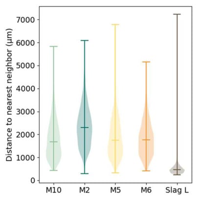
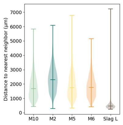
The neighbourhood relations were evaluated using the coordinates of the centre of mass coordinates of each identified cluster. Figure 6 presents violin plots of the distance to the nearest neighbour for individual clusters in Slag P at four different macroscopic regions (M10, M2, M5, and M6) and in Slag L. The analysis follows the approach established by Friebel et al. [35], where spatial relations between discrete objects are used to quantify packing state, clustering, and heterogeneity [35]. It shows a clear distinction between Slag P and Slag L. The latter derives from the smaller overall cluster size and therefore having a higher number of clusters in the sample.
Figure 6.
Violin plots describing the distances towards the nearest neighbour between objects for pilot scale slag experiment (Slag P) in four different positions (M10, M2, M5, M6), and lab-scale slag experiment (Slag L).
For Slag P, all four investigated positions exhibit broad nearest-neighbour distance distributions with pronounced upper tails extending to several millimetres. M2 shows the highest mean distance, approximately 2350 µm, whereas the mean distances for the other positions is approximately 1830 µm. Looking at the violin shape, M2 has broader distribution on the mean value, while the other three positions tend to show broadest distribution on the lower value. The overlap between the distributions indicates a common pilot-scale spacing regime, while their different widths and upper tails demonstrate local variations in cluster density. This distinction is important: the cluster-size distributions are broadly comparable among the investigated positions, whereas the local spacing between clusters remains heterogeneous.
In contrast, Slag L shows a narrower distribution with a mean distance around 500 µm. The smaller spacing is consistent with the much smaller connected EnAM grains and their higher number density in the lab-scale slag. The wider tail of the Slag L distribution is associated with the EnAM-poor region in the middle part of the slag body (Figure A1).
The nearest-neighbour analysis therefore complements the cluster-size comparison rather than contradicting it. At pilot scale, similar characteristic cluster sizes can coexist with locally heterogeneous cluster spacing. Such spatial variation is consistent with a larger solidifying slag body in which local heat transfer and melt conditions may vary. In Slag L, the smaller characteristic EnAM clusters and shorter neighbour distances indicate a finer spatial scale of the EnAM distribution.
For downstream mechanical processing, the cluster size (Figure 5) and nearest-neighbour distance (Figure 6) define a first characteristic length scale for selective removal of gangue surrounding the EnAM-rich regions. Because the typical separation between clusters is on the millimetre scale, an initial comminution stage may allow partial removal of the non-Al-rich matrix before finer liberation of the internally intergrown LiAlO2 and Mn-Al spinel phases is targeted.
3.2. Intergrowth of the Lithium Aluminate and Spinel from XCT, SEM-EDX
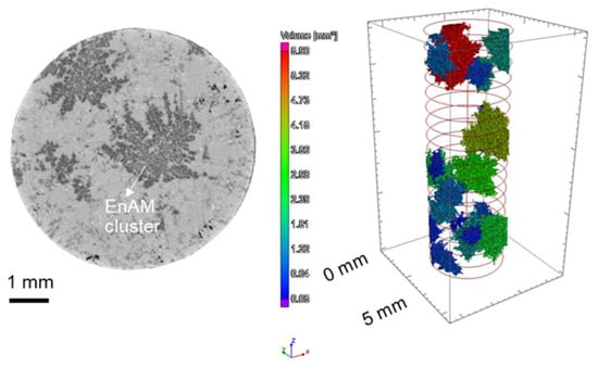
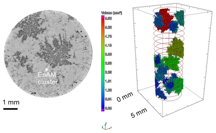
To complement the macroscopic µXRF analysis, micro-scale investigations were carried out using XCT and SEM-EDX to observe the 3D internal structure, morphology, and phase intergrowth of individual EnAM clusters. Previous work [31] demonstrated that image segmentation and watershed-based analysis can resolve internal structures within such clusters. In Slag P, however, mm-range cluster size means that the field of view presented in Figure 7 only captured a few clusters within the sample. The data set did not give enough individual data points for the cluster size distribution based on the XCT measurement. XCT volume of the drill sample shows that clusters are spatially separated but consist of highly irregular intergrown crystals of the target phase.
Figure 7.
Left: two-dimensional cross sections of slag sample from XCT showing EnAM clusters, right: three-dimensional visualisation of the EnAM clusters in a drill cylinder sample; the colour code distinguishes the clusters and provides information on their volume.
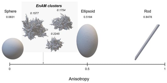
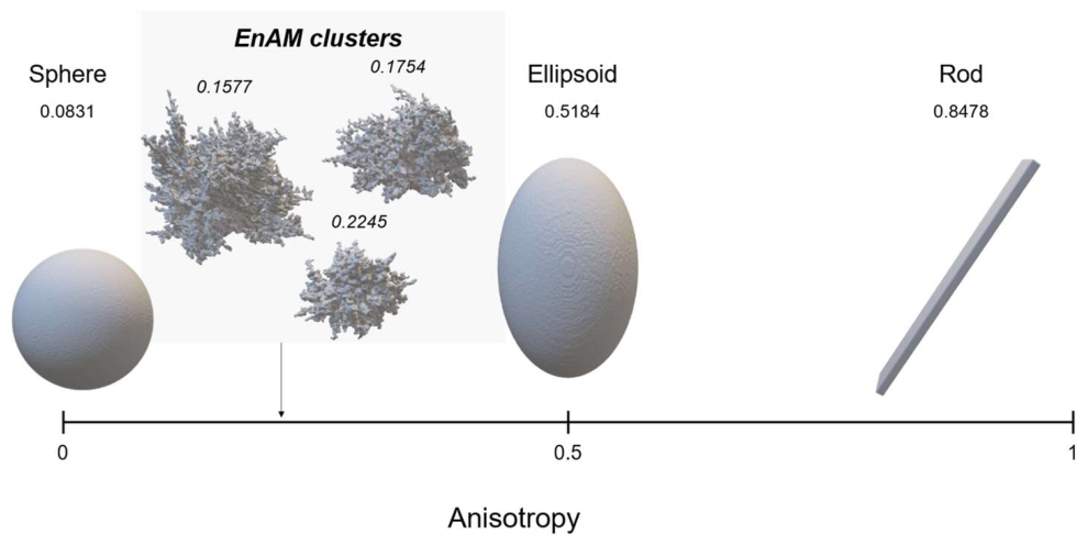
Figure 8 presents the cluster shape in more detail and summarises the anisotropy estimation of EnAM clusters segmented from XCT data, together with DA values obtained for defined reference shapes such as sphere, ellipsoid, and rod. DA has been defined, and its value was obtained using Equation (1). Note that an anisotropy value of 0 means that the sample is fully isotropic, e.g., a sphere, and a value of 1 means completely anisotropic, such as rod-like or needle-like structure [39]. The spherical reference shape yields DA values close to zero, representing the isotropic end, whereas elongated reference geometries (ellipsoid and rod) show substantially higher DA values, reflecting pronounced directional orientation. The estimated DA of EnAM clusters in Slag P were consistently low, ranging from 0.15 to 0.22. At their surface, the clusters showed a dendritic morphology; the low DA values nevertheless demonstrated that these clusters did not exhibit a dominant preferred orientation, having a compact core, respectively, at the scale resolved by XCT. Variations in DA were observed between individual EnAM clusters, as was expected from voxel discretation, cluster size, and segmentation uncertainty. No systematic trend toward higher DA values was observed. Overall, the comparison with defined reference shapes shown in Figure 8 demonstrated that EnAM clusters were grown predominantly isotropically. Their dendritic appearance therefore showed branching growth in multiple directions rather than directional elongation, resulting in uniform cluster growth within the analyzed spatial resolution in 3D.
Figure 8.
Degree of anisotropy (DA) of a segmented lithium aluminate (EnAM) cluster derived from XCT data, compared with defined reference shapes. The DA quantifies the amount of directional orientation in the structure, with DA = 0 indicating a completely isotropic structure with no preferred orientation and DA = 1 representing an extreme prevailing orientation. The DA values were estimated at defined number of angles (2000) with defined number of lines along each angle (100/100).
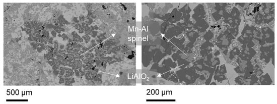
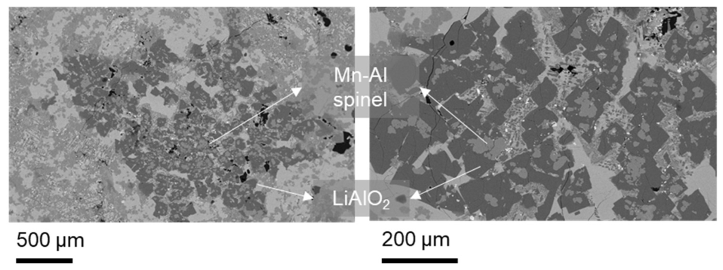
SEM imaging in Figure 9 showed that the dendritic EnAM clusters were in fact intergrowths of at least two phases, lithium aluminate and Mn-Al spinel. At the macroscopic scale of the µXRF measurement, Al was used a proxy for the target EnAM, and here it becomes clear that the detection is not explicit. Fortunately, Li-Al and Mn-Al spinel are grouped and in the sample so that the Al signal of the µXRF does not generate a false positive response for Li. The BSE images showed that close intergrowth with no sharp boundaries occurs between phases at the cluster-scale. Mn-Al spinels were formed continuously within LiAlO2 occurring as an interstitial phase. At higher magnification, the lithium aluminate and Mn-Al spinel occurrence implies unstable, transport-limited growth at the crystal melt interface. As a result, the cluster shape reflects the composite cluster growth. The XCT and SEM images show a consistent irregularity of the cluster. It can also be observed that these phases were co-crystallised rather than sequential precipitation occurring. This means that EnAM grain-size distributions derived from intensity-only, both in 3D XCT and 2D BSE segmentation, will be biased, because intergrowth clusters may be miscounted as larger single grains.
Figure 9.
Back-scattered electron (BSE) images of an EnAM cluster as an example in pilot-scale Slag P.
At XCT resolution, the intergrowth is partly below the voxel scale and manifests as a single object, while high-resolution SEM resolves the sub-grains and their interfaces. The combined XCT and SEM-EDX results demonstrate that the clusters have intergrown phases with complex internal morphology. The intergrowth nature of LiAlO2 and Mn-Al spinel implies that the liberation forms individual LiAlO2 grains that form the cluster during comminution, which might be limited in downstream processing. Thus, in the mechanical processing, a second level of liberation should be targeted, which aims at the liberation of the two finely intergrown spinel types that form the matrix material in the slag. The mixture of both spinel types should then be recovered.
These investigations confirm that pilot-scale slag solidification produces complex, approximately isotropic EnAM-rich clusters with pronounced internal phase intergrowth. Although related morphological trends are already observed at the laboratory scale, their characteristic size, connectivity, and internal grain structure change substantially upon scale-up.
3.3. EBSD Analysis of Lithium Aluminate Grain Structure
Building on the XCT and SEM-EDX results, the next step is to look more closely at the grain-scale structure inside these intergrown clusters. From the XCT greyscale contrast, some phases appear to be continuous and well-connected, but this can be misleading if they actually consist of many individual finer grains close to the resolution of the measurement with different orientations. In addition, defining reliable phase and grain boundaries is difficult where LiAlO2 and Mn-Al spinel showed overlapping gray values, so grain size cannot be quantified using SEM-EDX alone. Therefore, EBSD was used to provide crystallographic contrast and grain-orientation information, enabling boundary determination and a more reliable grain-size analysis of the LiAlO2 phase. To quantify it, grain boundaries need to be known, which requires grain-orientation information. EBSD adds crystallographic contrast that separates LiAlO2 from spinel even where BSE gray values overlap, enabling robust boundary placement and unbiased grain statistics.
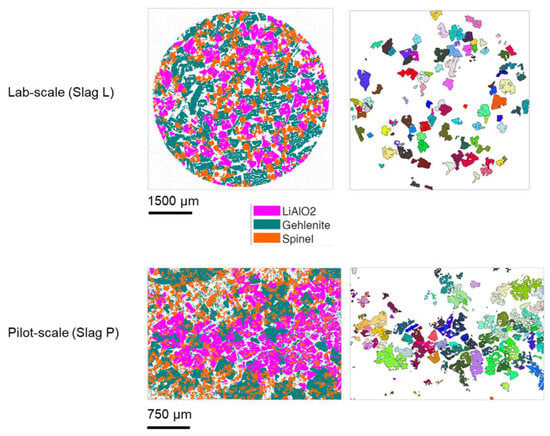
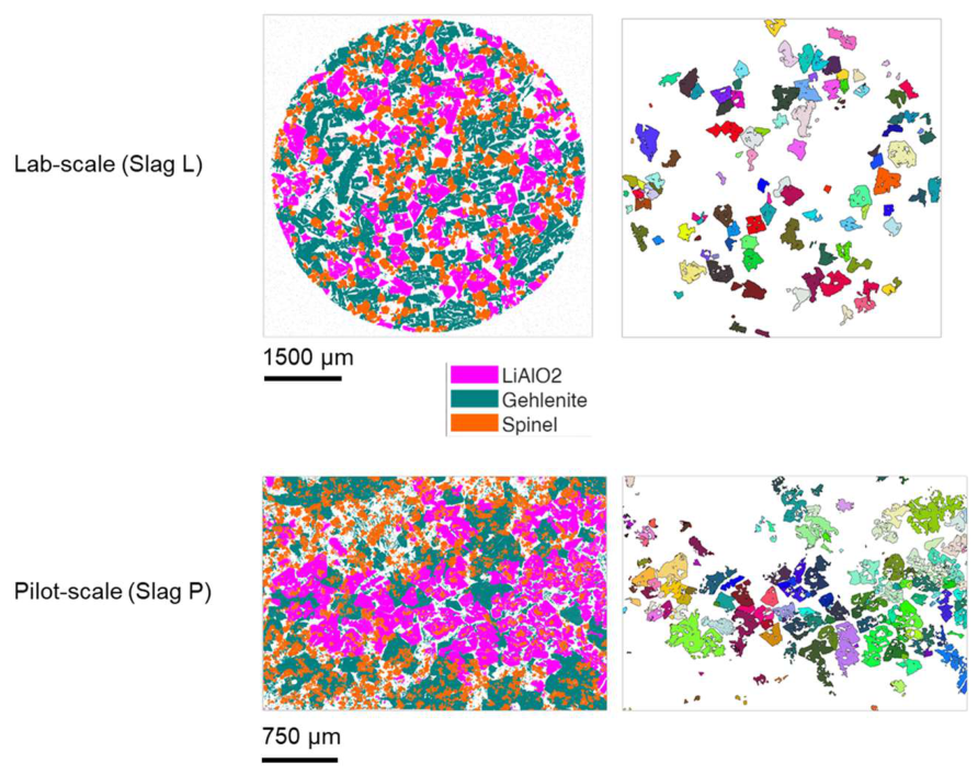
Figure 10 shows EBSD phase and grain maps of a representative cluster region originating from sample M6, providing detailed insight into the grain structure and orientation relationships of different phases. It also compares the lab-scale and pilot-scale slag samples. The EBSD results complement the XCT- and SEM-EDX-based observations by resolving how clusters consist of individual grains and how different phases are crystallographically arranged within the intergrowth. The left images are the indexed mineral phases based on the three-mineral phase databases, lithium aluminate (LiAlO2), Mn-Al spinel, and gehlenite. The right picture shows grain orientation and grain boundaries for each grain. It should be noted that the different colours correspond to different orientations, and thus individual grains. It shows that although the indexed phases seem to be connected, they still consist of multiple individual grains, indicating multiple nucleation events during solidification. The same goes for both the lab-scale experiment (Slag L) and pilot scale experiment (Slag P). The difference is that Slag P shows clustering of the EnAM, while Slag L, though connected, does not show a tendency for clustering. While Slag L forms continuous single crystals, Slag P forms clusters that are composed of numerous grains with irregular shapes and variable sizes.
Figure 10.
Left: false colour image with classified mineral phase from EBSD, and right: the corresponding grain size boundaries of lithium aluminate (LiAlO2. Different colours on the right images refer to individual grain with different orientation.
No preferred crystallographic orientation was observed in either slag. In slag P, the individual grains within the investigated EnAM cluster exhibited different orientations, indicating that the cluster is composed of multiple crystallographically distinct grains rather than a single continuous crystal. Despite the random grain orientations and irregular internal intergrowth, the EnAM clusters showed relatively low shape-anisotropy values, indicating an approximately isotropic overall morphology. The EnAM grain sizes of Slag P were smaller than those of Slag L. This is an interesting property, as the cluster size of Slag P was significantly larger than that in EnAM Slag L, but with the actual grain size boundaries, Slag P consisted of smaller grains that form larger clusters.
3.4. EnAM Comparison in Both Experimental Scales
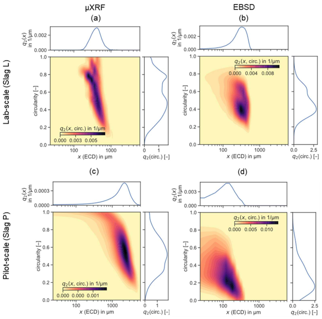
The size and shape distribution of the two different experimental series, Slag L and Slag P, are plotted as multi-dimensional particle property distributions using area-based kernel density estimation (KDE) [40,41] in Figure 11. The structural level represented by each distribution depends on the measurement method: µXRF describes EnAM clusters, whereas EBSD resolves individual LiAlO2 grains. Figure 11 therefore compares both scale-dependent morphology and method-dependent structural resolution. The main peak of the 2D size-shape distribution differs between the measurement methods. The main peak, the 2D modal value, shifts from the µXRF and EBSD data to finer particle size and less circular shape.
Figure 11.
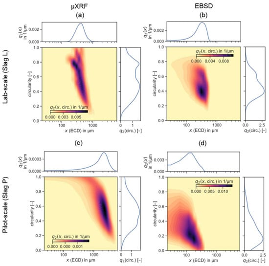
Area-weighted probability density distribution as a function of equivalent projected circle diameter (EQPC) and circularity with continuous representation through kernel density estimation. EnAM grain size in lab-scale experiment Slag L from µXRF (a) and from EBSD (b); EnAM cluster size including sub-samples M2, M5, M6, and M10 in Slag P from µXRF (c) and EnAM grain size from EBSD (d).
For Slag L, EnAM grain sizes derived from µXRF (Figure 11a) and EBSD (Figure 11b) are concentrated at relatively small sizes and high circularities. EnAM grains were concentrated in a region of circularity between 0.4 and 0.8. The µXRF result showed a slightly broader size range since this method detects larger spatial regions due to its lower spatial resolution compared to EBSD. In Slag L, the modal size is around 400 µm, while the circularity value shows a bimodal distribution with two peaks at around 0.4 and 0.8, based on the overview from µXRF in Figure 11a. The highest-density region occurs at approximately 200–300 µm and a circularity of about 0.8, indicating that many EnAM clusters are relatively compact. The two modal values of the shape are consistent with the granular and dendritic morphologies reported previously [30], which correspond to the granular shape as the higher circularity and dendritic shape as the lower circularity. The narrow size distribution and high circularity confirmed that crystallisation in the lab-scale slag was dominated by widespread nucleation and limited growth. Grains remained small, isolated, and weakly interconnected, in agreement with EBSD phase maps (Figure 11b).
For slag P, the data for all positions from µXRF (integral data set including M2, M5; M6, and M10) are plotted as one graph in Figure 11c. In Slag P, the peak of the cluster size moves to much larger sizes (around 2250 µm) and a main mode at lower circularity (roughly 0.4–0.7). This shift means that the EnAM object in the scaled-up slag is not only coarser, but also consistent with the clustering morphologies rather than isolated grains. Note that since this distribution originates from µXRF, the data of Slag L represents the single EnAM, while the data of Slag P represents the EnAM cluster. A less distinct second mode at circularity values < 0.4 reflects strongly dendritic or irregular clusters such as that shown in Figure 5c.
Despite the significant shift in the modal size between Slag L and Slag P, the µXRF-based distributions revealed a similar overall relationship between EnAM size and shape at both scales. In both experimental series, the multi-dimensional distribution showed the ranges from smaller, more compact EnAM clusters tower to larger clusters with lower circularity. Thus, the pilot-scale distribution can be interpreted as an extension of the size and shape trend already observed at lab-scale rather than as a fundamentally different crystallisation behaviour. This similarity is particularly relevant for evaluating the scale-up of the EnAM concept. The stronger occurrence of large, less compact EnAM clusters in Slag P may be related to differences in heat transport during solidification. With increasing melt volume, the higher heat-transport resistance results in slower cooling of the interior of the slag body, providing more time for crystal growth and intergrowth.
EBSD distributions in Figure 11b,d provide a complementary comparison because they represent individual LiAlO2 grains. Slag L shows a peak grain size of roughly 300 µm, whereas Slag P shows a broader distribution shifted toward finer sizes, with a main range of approximately 100–200 µm. The circularity of the grains in Slag P is lower than that in Slag L. This can be also seen in Figure 10, where pilot-scale EnAM grains appeared less compact and more irregular within the intergrown clusters. The combined µXRF and EBSD results therefore reveal a scale-up effect: Slag P contains much larger EnAM-rich clusters, but these clusters are composed of comparatively fine, irregular LiAlO2 grains. This distinction is relevant to downstream liberation because previous studies [20,32] reported that liberated LiAlO2 in Slag P occurred predominantly in the fine particle size range below 15 µm.
The apparent differences between the µXRF-based surface mapping and EBSD help to explain these distributions. µXRF has limited spatial resolution that blurs fine intergrowth; as a result, connected phase regions in the surface maps can appear as single, large EnAM objects even if they are internally composed of multiple grains and intergrown phases. EBSD, in contrast, separates grains by crystallographic orientation and provides boundary definitions even when compositional contrast is weak or phases appear as connected in the other characterisation method used (µXRF, XCT, and SEM). This is important as the coarse, low-circularity EnAM objects in Slag P are likely a continuous region that are actually built from multiple grains and intergrowth domains.
3.5. Implications and Challenges in Scaling-Up Experiment
As reported in Table 2 and [30], the pilot scale test (Slag P) produced less lithium aluminate (7.5–10.5 wt. %) compared to lab-scale Slag L (11.2–14.4 wt. %). This decrease in LiAlO2 at pilot-scale trial is attributed to slag-crucible interactions during casting and controlled cooling. During the casting procedure was the loss of approximately 12 kg of liquid slag, which solidified along the casting nose in the setup. This may have contributed to a reduction in lithium content, since the casting nose is constructed from alumina-based lining. Although the laboratory-derived cooling schedule was retained, the pilot-scale trial used a clay–graphite crucible containing silicon-bearing constituents. Crucible corrosion can modify the melt composition and favor competing phases. Lucas et al. [11] reported increased Si and Al concentrations following slag remelting in comparable crucibles, promoting Li2MnSiO4 and Al-rich spinel at the expense of LiAlO2. The significant fractions of LiAlSiO4, Li2MnSiO4 and Mn-Al spinel in the pilot slag (Table 2) are consistent with this explanation. However, the extent of crucible-derived contamination was not quantified in this study.
Additionally, it was also observed that some slag remained in the vessel after casting. This retention can be attributed to a loss of temperature during the casting procedure by stopping burner operation. This issue should be potentially mitigated by elevating the melting temperature by around 50 °C before casting. However, this approach may also be too aggressive for the lining, possibly leading to increased wear or damage. For this purpose, investigations into changes in viscosity and density should be conducted beforehand to ensure reliability regarding the expected phase formation. The other cause may be related to sources of pollution associated with cross-contamination in semi-industrial furnaces, where components from a previous process (metal, slag) remain solidified within the furnace refractory and contaminate the next batch.
Furthermore, the crucible used for the large-scale test contains a higher amount of silicon (SiC, SiO2) than the laboratory test. This may have affected the amount of silicon transferred to the slag during the extended cooling stage, promoting greater precipitation of gehlenite, eucryptite, and silicates. This interaction can be used to explain the mineral composition difference from the lab-scale and pilot-scale experiments.
The Mn-Al spinel is intergrown with lithium aluminate, which possibly occurs due to the larger thermal gradient in the pilot-scale furnace that prohibits the mobilisation of the phases. The solidification temperature interval to promote the formation of both phases is between 1200 °C and 1050 °C. Adding more holding time makes more sense for the pilot scale to give more time for crystal growth of the phase of interest.
The clear difference between the lab-scale slag and pilot-scale slag can be explained mainly by the difference of thermal gradient of both scales and the slag–crucible interaction. In the pilot-scale, the larger melt volume and slower heat extraction likely mean that the slag stayed for longer at a temperature above the selected holding temperature. This increases the time window in which the crystal nuclei can grow, grains can coarsen, and intergrowth textures can develop. With more time, phases such as LiAlO2 and Mn-Al spinel do not only form but can continue to grow into each other, producing the complex, isotropic clusters that were seen in XCT (Figure 7) and SEM (Figure 8). This longer growth time also supports grain coarsening between neighbouring crystals, which makes the internal morphology more intergrown.
In addition, the EBSD observation that Slag P shows a stronger tendency for EnAM clustering can be linked to the state of the matrix phase during solidification. If the matrix remains liquid (or at least partially liquid) for a longer time in the pilot-scale experiment, the mobility of EnAM grains is higher: crystals can translate and rotate in the melt, and they can be brought together by the internal melt flow, density-driven settling, or simple collision during growth. This enhances the probability that EnAM grains aggregate and form clusters before the matrix finally settles in the spatial arrangement. In contrast, in the lab-scale experiment, the matrix likely reaches a rigid/solid state much faster, which limits crystal movement. As a result, phases may still appear connected (as EBSD shows they can consist of multiple grains), but they do not show the same pronounced clustering behaviour.
From a crystallisation point of view, the observed spatial association between LiAlO2 and Mn-Al spinel is consistent with the expected solidification behaviour of this slag [42,43,44,45]. Mn-Al type spinel is a highly stable, refractory oxide in Mn-Al-bearing melts and can precipitate early once the melt becomes locally supersaturated in MnO-Al2O3 (favoured at higher oxygen potential where Mn readily enters spinel) [16,46]. The early-formed spinel grains could subsequently provide solid interfaces that facilitate the heterogeneous nucleation of Li-bearing aluminates becoming stable during further cooling or isothermal holding. Subsequent LiAlO2 growth at or near these interfaces could produce the observed rim- and branch-like intergrowth textures and result in mechanically interlocked multiphase clusters. This interpretation is compatible with the close spatial association between LiAlO2 and Mn-Al spinel observed in the EBSD phase maps. However, because EBSD does not directly resolve the temporal precipitation sequence, the proposed spinel-assisted nucleation and growth mechanism cannot be conclusively established from the present results.
Scaling up from lab-scale to pilot-scale changes the crystallisation path mainly through a different thermal history and melt dynamics. The larger melt volume cools more slowly (lower surface-area-to-volume ratio), so the slag spends longer in the temperature interval where spinel and LiAlO2 are stable while the matrix is still partly liquid. This extended time window promotes continued nucleation on existing crystals, solute-diffusion-driven coarsening, and impingement, so intergrowth textures can fully develop and settle in before complete solidification. In addition, stronger thermal gradients and longer-lived convection in the pilot-scale melt redistribute heat and solute, supporting sustained spinel growth and heterogeneous nucleation of LiAlO2 at spinel–melt interfaces. Because the matrix remains liquid longer, crystals can also move, collide, and aggregate, increasing clustering and multiphase attachment.
The present study investigated one pilot-scale production batch. µXRF measurements on four spatially separated blocks enabled comparison of surface EnAM-cluster distributions, whereas XCT and EBSD characterised a local volume and area within block M6. The observed three-dimensional intergrowth and grain-size distributions therefore described the investigated regions and cannot be generalised to the entire slag body. Additional spatially distributed XCT cores and EBSD maps are needed to assess within-batch microstructural variability, while independent pilot trials are required to establish batch-to-batch reproducibility.
Overall, scaling up therefore affects not only size, but also connectivity and intergrowth, making the pilot-scale texture more complex but on the other hand more representative for future industrial conditions. To face these challenges, any scale-up of EnAM production should go along with an appropriate thermal management, and design of the process should use temperature field simulation. The latter has to include not only the temperature transport but the phase transition as well.
4. Conclusions and Outlook
This study demonstrates the feasibility of transferring the engineered artificial mineral concept from a 5 kg laboratory-scale slag to a 125 kg pilot-scale process while retaining lithium aluminate as a targeted Li-bearing phase. The pilot-scale slag contained 7.5–10 wt. % LiAlO2, compared with 11.2–14.4 wt. % in the previous lab-scale trials, showing that target-phase formation was achieved but not fully preserved during scale-up. The multiscale characterisation workflow was essential for distinguishing structural levels that cannot be described by a single analytical method: µXRF revealed the macroscopic distribution of EnAM-rich clusters, XCT resolved their three-dimensional architecture, SEM-EDX showed the internal LiAlO2 and Mn-Al spinel intergrowth and EBSD resolved individual LiAlO2 grains and crystallographic boundaries.
The central scale-up finding is that the investigated regions of Slag P contained larger EnAM-rich clusters composed of comparatively fine, irregular LiAlO2 grains. Nevertheless, both scales showed a related progression from smaller, compact EnAM objects toward larger, less compact structures, indicating that the pilot-scale morphology represents a scale-modified continuation of tendencies already observed in the laboratory experiments. The results therefore support the use of lab-scale trials for screening EnAM-forming compositions and cooling strategies, while showing that pilot-scale thermal history, transfer conditions and slag-reactor interactions must be considered explicitly when predicting industrially relevant microstructures. Future work should combine internal temperature measurements and thermal modelling with process optimisation to increase LiAlO2 yield, control intergrowth and tailor the characteristic length scales required for efficient downstream liberation and recovery.
Author Contributions
Conceptualization, C.R.; methodology, C.R., J.W. and H.I.L.; software, C.R. and S.-O.M.; validation, C.R.; formal analysis, C.R., J.W., H.I.L., R.M., M.F.H. and S.-O.M.; investigation, C.R., J.W. and S.-O.M.; data curation, C.R.; writing—original draft preparation, C.R., J.W. and S.-O.M.; writing—review and editing, E.L., O.P., B.F., and U.A.P.; visualization, C.R.; supervision, E.L., O.P., B.F. and U.A.P.; project administration, U.A.P.; funding acquisition, B.F. and U.A.P. All authors have read and agreed to the published version of the manuscript.
Funding
This research was funded by the Deutsche Forschungsgemeinschaft (DFG, German Research Foundation) in the priority program 2315 “Engineered artificial minerals (EnAM)—A geo-metallurgical tool to recycle critical elements from waste streams” with grant number 470552553 and EXCITE Network for the EBSD measurement.
Data Availability Statement
Primary data and Python 3 notebooks that reproduce all necessary parts of the figures used in the text are available via the repository for digital research data of the TU Dresden and the TU Bergakademie Freiberg under https://doi.org/10.25532/OPARA-1585 (accessed on 9 October 2026).
Acknowledgments
The authors acknowledge the financial support of the DFG, which made this project possible, and Helmholtz Institute Freiberg for providing the M4 Tornado µXRF equipment, Doreen Ebert for XRD analysis, Roland Wuerkert and his sample preparation team for the sample preparation, as well as Institute for Ceramics, Refractories and Composites at TU Bergakademie Freiberg for SEM-EDX measurement. During the preparation of this manuscript, the authors used OpenAI (GPT–5.5) for the purposes of language editing, improving readability, and clarity, and assisting with refinement of the manuscript text. The authors reviewed and edited all AI-assisted content and took full responsibility for the final content of the manuscript.
Conflicts of Interest
Author Hugo Ignacio Lucas was employed by the company Forschungszentrum Jülich GmbH. The remaining authors declare that the research was conducted in the absence of any commercial or financial relationships that could be construed as a potential conflict of interest.
Appendix A
Figure A1.
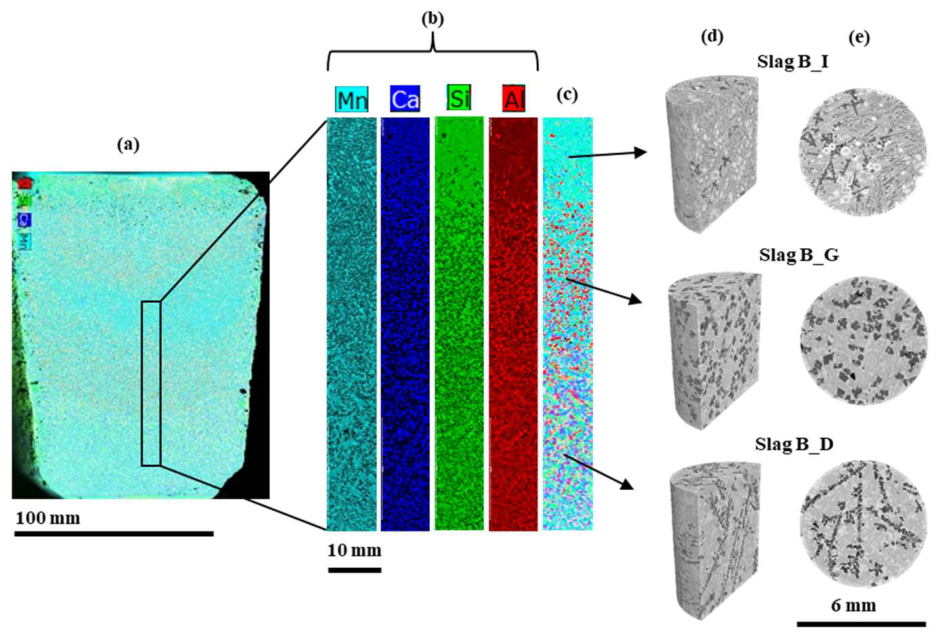
Element distribution of the lab-scale Slag L from µXRF (a–c) and XCT results (d,e) from drill core sample from selected position: (a) Overlay of Al, Si, Ca, and Mn element map to get a chemical overview of the slag horizontal flat surface with 150 µm resolution; (b) individual element map and; (c) overlay of element map with 50 µm resolution in the area with different morphology transition; (d) cut 3D volume of the drill cores and (e) the reconstructed horizontal cross-section [30].
References
- Velázquez-Martínez, O.; Valio, J.; Santasalo-Aarnio, A.; Reuter, M.; Serna-Guerrero, R. A Critical Review of Lithium-Ion Battery Recycling Processes from a Circular Economy Perspective. Batteries 2019, 5, 68. [Google Scholar] [CrossRef] [Scilit]
- Werner, D.; Peuker, U.A.; Mütze, T. Recycling Chain for Spent Lithium-Ion Batteries. Metals 2020, 10, 316. [Google Scholar] [CrossRef] [Scilit]
- Sommerfeld, M.; Vonderstein, C.; Dertmann, C.; Klimko, J.; Oráč, D.; Miškufová, A.; Havlík, T.; Friedrich, B. A Combined Pyro- and Hydrometallurgical Approach to Recycle Pyrolyzed Lithium-Ion Battery Black Mass Part 1: Production of Lithium Concentrates in an Electric Arc Furnace. Metals 2020, 10, 1069. [Google Scholar] [CrossRef] [Scilit]
- Sommerville, R.; Shaw-Stewart, J.; Goodship, V.; Rowson, N.; Kendrick, E. A review of physical processes used in the safe recycling of lithium ion batteries. Sustain. Mater. Technol. 2020, 25, e00197. [Google Scholar] [CrossRef] [Scilit]
- Kaas, A.; Wilke, C.; Vanderbruggen, A.; Peuker, U.A. Influence of different discharge levels on the mechanical recycling efficiency of lithium-ion batteries. Waste Manag. 2023, 172, 1–10. [Google Scholar] [CrossRef] [Scilit]
- Kaas, A.; Wilke, C.; Peuker, U.A. Influence of shredder and mill settings on the material recoveries and product qualities of a two-stage mechanical recycling process of automotive lithium-ion batteries. Waste Manag. 2025, 204, 114912. [Google Scholar] [CrossRef] [Scilit]
- Wilke, C.; Kaas, A.; Peuker, U.A. Influence of the cell type on yield and composition of black mass deriving from a mechanical recycling process of automotive Lithium-ion batteries. Next Sustain. 2024, 4, 100050. [Google Scholar] [CrossRef] [Scilit]
- Li, H.; Ranneberg, M.; Fischlschweiger, M. High-Temperature Phase Behavior of Li2O-MnO with a Focus on the Liquid-to-Solid Transition. JOM 2023, 75, 5796–5807. [Google Scholar] [CrossRef] [Scilit]
- Paul, A.; Lizhen, P.G.; Recheal, T.; Ali, S. Sustainable Lithium and Cobalt Recovery from Spent Lithium-ion Batteries: Best Practices for the Future. A review. J. Anal. Tech. Res. 2024, 6, 43–77. [Google Scholar] [CrossRef] [Scilit]
- Meshram, S.; Raut, S.P.; Ansari, K.; Madurwar, M.; Daniyal, M.; Khan, M.A.; Katare, V.; Khan, A.H.; Khan, N.A.; Hasan, M.A. Waste slags as sustainable construction materials: A compressive review on physico mechanical properties. J. Mater. Res. Technol. 2023, 23, 5821–5845. [Google Scholar] [CrossRef] [Scilit]
- Lucas, H.; Diaz, F.; Rachmawati, C.; Ranneberg, M.; Weiss, J.; Song, W.; Möckel, R.; Graupner, T.; Peuker, U.; Friedrich, B. Large-Scale Feasibility of the EnAM-Concept Demonstrated in the Pyrometallurgical Treatment of NMC Lithium-Ion Battery Black Mass and Full Cells. J. Sustain. Metall. 2026, 12, 3518–3540. [Google Scholar] [CrossRef] [Scilit]
- Qiu, H.; Li, H.; Fischlschweiger, M.; Ranneberg, M.; Graupner, T.; Lucas, H.; Stallmeister, C.; Friedrich, B.; Yagmurlu, B.; Goldmann, D. Valorization of lithium containing slags from pyrometallurgical recycling route of spent lithium-ion batteries: The enrichment of γ-LiAlO2 phase from thermodynamic controlled and modified slags. Miner. Eng. 2024, 217, 108918. [Google Scholar] [CrossRef] [Scilit]
- Vollbrecht, M.; Pramanik, K.; Colombi Ciacchi, L.; Mädler, L. Investigating the Compositional Space of Gas-Phase Synthesized Fayalitic Model Slags Aiming at Cobalt Recovery. J. Sustain. Metall. 2024, 10, 1634–1648. [Google Scholar] [CrossRef] [Scilit]
- Schirmer, T.; Wahl, M.; Bock, W.; Kopnarski, M. Determination of the Li Distribution in Synthetic Recycling Slag with SIMS. Metals 2021, 11, 825. [Google Scholar] [CrossRef] [Scilit]
- Schnickmann, A.; De Abreu, D.A.; Fabrichnaya, O.; Schirmer, T. Stabilization of Mn4+ in Synthetic Slags and Identification of Important Slag Forming Phases. Minerals 2024, 14, 368. [Google Scholar] [CrossRef] [Scilit]
- de Abreu, D.A.; Fabrichnaya, O. Thermodynamic modeling of the Mn–Si–O system. Phys. Chem. Miner. 2024, 52, 2. [Google Scholar] [CrossRef] [Scilit]
- Siddique, A.; Boelens, P.; Long, F.; Zhou, S.; Cnudde, V.; Leißner, T. Characterization of Magnetic and Mineralogical Properties of Slag Particles from WEEE Processing. Minerals 2023, 13, 1417. [Google Scholar] [CrossRef] [Scilit]
- Buchmann, M.; Borowski, N.; Leißner, T.; Heinig, T.; Reuter, M.A.; Friedrich, B.; Peuker, U.A. Evaluation of Recyclability of a WEEE Slag by Means of Integrative X-Ray Computer Tomography and SEM-Based Image Analysis. Minerals 2020, 10, 309. [Google Scholar] [CrossRef] [Scilit]
- Võ, T.T.; Leißner, T.; Peuker, U.A. Utilizing X-ray Computed Tomography for Lithium Slag: A Guide to Analyzing Microstructure and Its Potential Influence on Liberation. Minerals 2024, 14, 42. [Google Scholar] [CrossRef] [Scilit]
- Javadi, M.; Rachmawati, C.; Wollmann, A.; Weiss, J.; Lucas, H.; Möckel, R.; Friedrich, B.; Peuker, U.; Weber, A.P. Enhancing Lithium Recovery from Slag Through Dry Forced Triboelectric Separation: A Sustainable Recycling Approach. Minerals 2024, 14, 1254. [Google Scholar] [CrossRef] [Scilit]
- Hellmers, S.; Qiu, H.; Yagmurlu, B.; Kwade, A. Modifying milling parameters: Impact on selective separation of lithium-rich phases in a thermodynamically designed battery slag. Clean. Eng. Technol. 2025, 24, 100857. [Google Scholar] [CrossRef] [Scilit]
- Reyes, F.; Lin, Q.; Cilliers, J.J.; Neethling, S.J. Quantifying mineral liberation by particle grade and surface exposure using X-ray microCT. Miner. Eng. 2018, 125, 75–82. [Google Scholar] [CrossRef] [Scilit]
- Leißner, T.; Mütze, T.; Bachmann, K.; Rode, S.; Gutzmer, J.; Peuker, U.A. Evaluation of mineral processing by assessment of liberation and upgrading. Miner. Eng. 2013, 53, 171–173. [Google Scholar] [CrossRef] [Scilit]
- Elwert, T.; Goldmann, D.; Strauss, K.; Schirmer, T. Phase composition of high lithium slags from the recycling of lithium ion batteries. World Metall.-Erzmetall 2012, 65, 163–171. [Google Scholar]
- Schirmer, T.; Qiu, H.; Li, H.; Goldmann, D.; Fischlschweiger, M. Li-Distribution in Compounds of the Li2O-MgO-Al2O3-SiO2-CaO System—A First Survey. Metals 2020, 10, 1633. [Google Scholar] [CrossRef] [Scilit]
- Wittkowski, A.; Schirmer, T.; Qiu, H.; Goldmann, D.; Fittschen, U.E.A. Speciation of Manganese in a Synthetic Recycling Slag Relevant for Lithium Recycling from Lithium-Ion Batteries. Metals 2021, 11, 188. [Google Scholar] [CrossRef] [Scilit]
- Li, H.; Qiu, H.; Schirmer, T.; Goldmann, D.; Fischlschweiger, M. Tailoring Lithium Aluminate Phases Based on Thermodynamics for an Increased Recycling Efficiency of Li-Ion Batteries. ACS ES&T Eng. 2022, 2, 1883–1895. [Google Scholar] [CrossRef] [Scilit]
- Li, H.; Qiu, H.; Ranneberg, M.; Lucas, H.; Graupner, T.; Friedrich, B.; Yagmurlu, B.; Goldmann, D.; Bremer, J.; Fischlschweiger, M. Enhancing Lithium Recycling Efficiency in Pyrometallurgical Processing through Thermodynamic-Based Optimization and Design of Spent Lithium-Ion Battery Slag Compositions. ACS Sustain. Resour. Manag. 2024, 1, 1170–1184. [Google Scholar] [CrossRef] [Scilit]
- Han, W.; Weiss, J.; Lu, X.; Munchen, D.; Jiang, C.; Lucas, H.; Ran, M.; Chen, W.; Friedrich, B. Engineered Artificial Minerals (EnAMs): Concept, Design Strategies, and Case Studies. Minerals 2025, 15, 1129. [Google Scholar] [CrossRef] [Scilit]
- Rachmawati, C.; Weiss, J.; Lucas, H.I.; Löwer, E.; Leißner, T.; Ebert, D.; Möckel, R.; Friedrich, B.; Peuker, U.A. Characterisation of the Grain Morphology of Artificial Minerals (EnAMs) in Lithium Slags by Correlating Multi-Dimensional 2D and 3D Methods. Minerals 2024, 14, 130. [Google Scholar] [CrossRef] [Scilit]
- Bahnmüller, S.; Hirschberger, P.; Võ, T.T.; Rachmawati, C.; Kwade, A.; Peuker, U.; Kruggel-Emden, H.; Schilde, C. Particle Size-and Structure-Dependent Breakage Behaviors of EnAM-Containing Slags. Minerals 2025, 15, 195. [Google Scholar] [CrossRef] [Scilit]
- Strube, F.; Guy, B.M.; Pereira, L.; Ebert, D.; Zgheib, A.; Fischer, M.; Möckel, R.; Schmidt, A.; Rudolph, M. Batch Flotation of Lithium-Bearing Slag—A Special Focus on the Phase Properties of Engineered Artificial Minerals for Enhancing the Recycling of End-of-Life Lithium-Ion Batteries. Minerals 2025, 15, 334. [Google Scholar] [CrossRef] [Scilit]
- Kaskes, P.; Déhais, T.; de Graaff, S.J.; Goderis, S.; Claeys, P. Micro-X-ray fluorescence (µXRF) analysis of proximal impactites: High-resolution element mapping, digital image analysis, and quantifications. In Large Meteorite Impacts and Planetary Evolution VI; Reimold, W.U., Koeberl, C., Eds.; Geological Society of America: Boulder, CO, USA, 2021; Volume 550. [Google Scholar]
- Schindelin, J.; Arganda-Carreras, I.; Frise, E.; Kaynig, V.; Longair, M.; Pietzsch, T.; Preibisch, S.; Rueden, C.; Saalfeld, S.; Schmid, B.; et al. Fiji: An open-source platform for biological-image analysis. Nat. Methods 2012, 9, 676–682. [Google Scholar] [CrossRef] [Scilit]
- Friebel, J.M.; Ditscherlein, R.; Ditscherlein, L.; Peuker, U.A. Three-Dimensional Characterization of Dry Particle Coating Structures Originating from the Mechano-fusion Process. Microsc. Microanal. 2024, 30, 179–191. [Google Scholar] [CrossRef] [Scilit]
- Odgaard, A. Three-dimensional methods for quantification of cancellous bone architecture. Bone 1997, 20, 315–328. [Google Scholar] [CrossRef] [Scilit]
- Schwartz, A.J.; Kumar, M.; Adams, B.L.; Field, D.P. Electron Backscatter Diffraction in Materials Science; Springer: New York, NY, USA, 2009. [Google Scholar]
- Bachmann, F.; Hielscher, R.; Schaeben, H. Texture Analysis with MTEX—Free and Open Source Software Toolbox. Solid State Phenom. 2010, 160, 63–68. [Google Scholar] [CrossRef] [Scilit]
- Kazhdan, M.; Funkhouser, T.; Rusinkiewicz, S. Shape matching and anisotropy. ACM Trans. Graph. 2004, 23, 623–629. [Google Scholar] [CrossRef] [Scilit]
- Buchwald, T.; Schach, E.; Peuker, U.A. A framework for the description of multidimensional particle separation processes. Powder Technol. 2024, 433, 119165. [Google Scholar] [CrossRef] [Scilit]
- Buchwald, T.; Ditscherlein, R.; Peuker, U.A. Beschreibung von Trennoperationen mit mehrdimensionalen Partikeleigenschaftsverteilungen. Chem. Ing. Tech. 2022, 95, 199–209. [Google Scholar] [CrossRef] [Scilit]
- Chakrabarty, S.; De Abreu, D.A.; Alhafez, I.A.; Fabrichnaya, O.; Merkert, N.; Schnickmann, A.; Schirmer, T.; Fittschen, U.E.A.; Fischlschweiger, M. Kinetics of γ-LiAlO2 Formation out of Li2O-Al2O3 Melt—A Molecular Dynamics-Informed Non-Equilibrium Thermodynamic Study. Solids 2024, 5, 561–579. [Google Scholar] [CrossRef] [Scilit]
- Hampel, S.; Alhafez, I.A.; Schirmer, T.; Merkert, N.; Wunderlich, S.; Schnickmann, A.; Li, H.; Fischlschweiger, M.; Fittschen, U.E.A. Engineering Compounds for the Recovery of Critical Elements from Slags: Melt Characteristics of Li5AlO4, LiAlO2, and LiAl5O8. ACS Omega 2024, 9, 24584–24592. [Google Scholar] [CrossRef] [Scilit]
- Tabero, P.; Frąckowiak, A.; Dąbrowska, G. Reinvestigations of the Li2O–Al2O3 system. Part I: LiAlO2 and Li3AlO3. Pol. J. Chem. Technol. 2021, 23, 30–36. [Google Scholar] [CrossRef] [Scilit]
- de Abreu, D.A.; Löffler, M.; Kriegel, M.J.; Fabrichnaya, O. Experimental Investigation and Thermodynamic Modeling of the Li2O–Al2O3 System. J. Phase Equilibria Diffus. 2024, 45, 36–55. [Google Scholar] [CrossRef] [Scilit]
- Shi, C.; Liu, Y.; Urata, K.; Yasui, S.; Abe, T.; Kobayashi, Y. Thermodynamic Investigation of MnAl2O4 Spinel Precipitation Behavior in Manganese Containing-Slag Systems. ISIJ Int. 2025, 65, 2269–2274. [Google Scholar] [CrossRef] [Scilit]

Disclaimer/Publisher’s Note: The statements, opinions and data contained in all publications are solely those of the individual author(s) and contributor(s) and not of MDPI and/or the editor(s). MDPI and/or the editor(s) disclaim responsibility for any injury to people or property resulting from any ideas, methods, instructions or products referred to in the content. |
© 2026 by the authors. Licensee MDPI, Basel, Switzerland. This article is an open access article distributed under the terms and conditions of the Creative Commons Attribution (CC BY) license.