


Abstract
To address the technical bottleneck of balancing the wideband noise (100–800 Hz) and aerodynamic performance of multi-blade centrifugal fans in air conditioning indoor units, this paper proposes a “frequency-domain target-driven” parametric design method for micro-perforated silencers. This method began with the precise identification of the 1/3-octave band noise spectrum to determine two noise peak clusters—200–400 Hz and 700–800 Hz—as the target suppression frequency bands. Based on Ma Dayou’s micro-perforated plate theory, a reverse mapping chain of “target frequency range → resonance frequency → structural parameters (hole diameter, perforation rate, rear cavity depth)” was established to enable the quantitative calculation of the silencer’s geometric parameters. Addressing engineering constraints related to manufacturing precision, clogging prevention, and structural stiffness for the theoretically optimal aperture size (0.24 mm), the aperture was adjusted to 1.0 mm through iterative recalculation of the relationship between plate thickness and perforation rate, while maintaining the perforated plate constant k ≈ 1.40 to ensure that the theoretical sound absorption frequency band remained unchanged. Test results show that under semi-anechoic chamber conditions (background noise ≤ 10 dB(A)), the micro-perforated silencer maintains airflow and power without attenuation across all airflow rates; noise peaks in the 200–400 Hz and 700–800 Hz frequency bands are significantly suppressed, and the full-band spectrum tends toward flatness. The average total noise level was reduced by 1 dB(A), and the average peak sound pressure level was reduced by 4 dB(A); the reduction in peak levels was four times that of the total reduction, revealing that the noise reduction mechanism of this method is “frequency-selective resonant absorption” rather than “uniform attenuation across the entire frequency band.” This study provides a quantifiable and reproducible design process for micro-perforated silencers, offering methodological support and engineering references for the development of low-noise compact fan systems in household appliances.
1. Introduction
In the early 1970s, Professor Ma Dayou pioneered the concept of micro-perforated absorbers (MPA), establishing the theoretical framework for calculating and designing micro-perforated noise reduction. The most significant feature of micro-perforated plate absorbers is their ability to achieve sound absorption and noise reduction without employing fibrous materials or other damping agents within the absorber structure, thereby realizing a long-sought vision among acoustic researchers [1,2]. This structure features an absorber composed of a micrometer-level perforated plate fixed to a structural surface. Due to the perforated plate’s inherent high acoustic impedance and low acoustic resistance, it exhibits broadband noise absorption properties without requiring any additional sound-absorbing materials. The micro-perforated absorber features a simple structure, with panel materials ranging from cardboard and plastic to film, offering material flexibility. Different panels can be selected based on specific noise reduction objectives. In recent years, MPA has been widely adopted across numerous fields, delivering excellent noise reduction performance.
Micro-perforated panel sound-absorbing structures are formed by drilling holes with diameters of approximately 0.1 mm on a thin plate, which are referred to as micro-perforations, typically with a perforation rate of 1–5%, and incorporating a cavity of specific thickness behind the plate to create a high acoustic impedance resonant sound-absorbing structure [3]. In 1975, Professor Ma Dayou proposed reducing the perforation diameter and eliminating the porous material behind the sound-absorbing panel, establishing the fundamental theory of micro-perforated panels [4]. Subsequently, in 1997, he presented the precise theory for micro-perforated panel absorbers based on an equivalent circuit approach [5]. Jiao Fenglei et al. [6]. investigated the limiting frequency bandwidth of micro-perforated plates and quantitatively analyzed the relationship between the maximum sound absorption coefficient and the upper limit of the sound absorption bandwidth. Liu Zhi’en et al. [7] proposed three composite micro-perforated plate sound-absorbing structures based on series-parallel combinations of micro-perforated plates. These were optimized using a multi-group genetic algorithm to form broadband sound-absorbing structures with high sound absorption coefficients. Wu Fei et al. [8] proposed a low-frequency broadband sound-absorbing metamaterial based on composite micro-perforated plates. Its structural thickness corresponds to sub-wavelength scales, exhibiting excellent low-frequency broadband sound absorption performance; Gao, N. et al. [9] investigated a composite absorber combining polyurethane foam and multilayer micro-perforated plates. By approximating the low-flow-resistance porous material as a fluid, they shifted the peak frequency toward lower frequencies without affecting the micro-perforated plate’s resonant absorption coefficient, thereby broadening the composite absorber’s operational range. Zuo Shuguang et al. [10] and Zhang Wenhui et al. [11] established a resonance frequency prediction model that explicitly reflects the relationship between each structural parameter and the resonance frequency of the silencer.
Currently, the processing techniques and corresponding manufacturing technologies for micro-perforated panels have undergone rapid development and application, enabling the fabrication of micro-perforated surfaces on various panel materials. In recent years, comprehensive research on the sound absorption characteristics of micro-perforated panels has been conducted through both theoretical studies and experimental validation [12,13,14], yielding valuable results particularly regarding their application in airflow diffusion fields and high sound intensity scenarios. Building upon the fundamental and accurate theory of micro-perforated panels proposed by Professor Ma Daxian, numerous micro-perforated sound-absorbing structures have been developed. Faisal Raffque et al. [15] presented a novel design for an acoustic membrane structure that employs a parallel arrangement of mixed foil sound resonators to improve sound absorption and insulation capabilities in the low-to-medium frequency range. Chun Gong et al. [16] presented an acoustic membrane design utilizing a thin foil sound resonance mechanism to enhance sound absorption and insulation performance. Faisal Rafque et al. [17] proposed a thin double-layer multiple parallel-arranged inhomogeneous micro-perforated panel (MPP) absorber in which the perfect low-frequency (i.e., 100–500 Hz) sound absorption with wider bandwidth is achieved with a deep sub-wavelength of thickness (100 mm). Faisal Rafque et al. [18] proposed a single layer of four parallel-arranged inhomogeneous micro-perforated panels (iMPP) as an absorber to achieve low-frequency sound absorption and wider frequency bandwidth. Faisal Rafique et al. [19] offered as a composite acoustic structure in this paper a single layer of a parallel-arranged inhomogeneous micro-perforated panel (iMPP) coupled with spider-web-designed cavities. Faisal Rafique et al. [20] proposed a micro-perforated panel (MPP) composite structure consisting of an inhomogeneous MPP (IMPP) backed with J-shaped cavities of different depths for low-frequency sound absorption. For signal processing, Wu Yanqi et al. [21] proposed a two-stage strategy for detecting the grout density inside prestressing tendon ducts in bridges, utilizing the LGBM model and multi-domain signal features to perform rapid qualitative diagnosis of grouting defects.
This paper focuses on the challenge of suppressing broadband noise from multi-blade centrifugal fans in air conditioning indoor units. Based on the micro-perforated noise attenuation mechanism, it proposes an integrated “source–path–dissipation” design concept: treating the micro-perforated plate not as an isolated accessory, but as a distributed acoustic boundary coupled with the volute duct. By constructing a response surface model relating the geometric parameters of the micro-perforated attenuation domain (pore diameter, porosity, and rear cavity depth) to the noise suppression effectiveness across characteristic frequency bands, a parametric design method for wideband noise attenuation was developed. This provides quantifiable design guidelines for wideband noise reduction in fan systems, thereby overcoming the technical bottleneck in the field of home appliance noise reduction, which currently relies heavily on trial-and-error and empirical iteration.
2. Sound Absorption Mechanism of Micro-Perforated Plate Silencers
2.1. The Sound Absorption Principle of Micro-Perforated Panels
Based on their sound-absorbing properties, sound-absorbing materials are currently classified into two categories: porous fibrous sound absorption and resonant sound absorption. The mechanism of fibrous sound absorption involves sound waves penetrating the interior of the fibrous material, where they interact with the fibers forming the slits through friction caused by viscosity and thermal conductivity, thereby gradually dissipating the sound energy. Fibrous sound absorption has a long history and offers the ad-vantages of high sound absorption coefficients, a wide frequency range, and low cost.
The principle of resonant sound-absorbing structures is based on the sound-absorption mechanism of Helmholtz resonators, and common applications include resonant sound absorption and micro-perforated panel sound absorption. Resonant sound absorption utilizes the driving force generated by acoustic Helmholtz resonant cavities to either impede or promote the propagation of airflow; each cavity in a micro-perforated panel can function as a Helmholtz resonant cavity. The basic operating principle is to convert the acoustic energy in the airflow into thermal energy through damping, thereby gradually dissipating the acoustic energy. Specifically, the air column flowing through the holes moves back and forth like a piston, and the hole walls exert a certain degree of damping on the air, using this damping to dissipate the acoustic energy. To achieve maximum absorption of aerodynamic sound energy, the resonator’s natural frequency can be matched to the frequency of the incident sound wave, thereby inducing resonance. At this point, the air column moves most vigorously within the holes, the damping effect reaches its maximum, and sound energy is absorbed to the greatest extent. The sound absorption frequency is determined by the structural dimensions of the silencer; the range of absorption frequencies can be controlled by altering the natural frequency of the micro-perforated plate.
Resonant sound-absorbing materials effectively leverage the characteristics of resonators to dissipate sound energy in a more targeted manner. Compared to porous fibrous sound-absorbing materials, they offer advantages such as resistance to high-speed airflow impacts, high temperatures, and corrosion; however, their main drawback is a narrower sound absorption frequency range. In recent years, with advancements in materials science and growing emphasis on health-safe materials, the application of novel, healthy, and fiber-free sound-absorbing materials has emerged as a new trend in the field of noise control [22].
Micro-perforated silencers are being applied in an increasing number of fields, and their excellent noise reduction and aerodynamic performance indicate promising prospects for future development. A micro-perforated plate structure consists of a thin plate with tiny holes and a cavity behind the plate. Many micro-perforated structures are arranged in parallel to form the micro-perforated plate structure. The micro-perforations can be approximated as circuit elements with acoustic mass and acoustic resistance. If the micro-hole diameter is much smaller than the spacing between holes, the mutual influence of the micro-holes in the micro-perforated plate can be neglected.
2.2. Theory of Micro-Perforated Sound-Absorbing Structures
The sound absorption characteristics of a micro-perforated plate sound-absorbing structure can be determined using the equivalent circuit principle, and the commonly used formula for calculating the acoustic impedance ZD of the cavity behind the micro-perforated plate is [4].
The ratio of absorbed sound power to incident sound power is called the sound absorption coefficient. Under normal incidence, this ratio is
In the equation:
r = relative acoustic resistance of the micro-perforated panel
m = relative acoustic mass of the micro-perforated panel
y = the ratio of acoustic impedance to characteristic impedance
In the equation: λ represents the wavelength.
From Equation (2), the maximum sound absorption coefficient as a function of frequency is
The frequency at which the sound absorption coefficient is greatest is the resonance frequency, satisfying:
In the equation: f0 is the frequency at which maximum sound absorption occurs (or the resonance frequency); λ0 is the corresponding wavelength.
The value of y when the sound absorption coefficient is half its maximum value satisfies
In the equation:
In the equation: f1 and f2 are the frequencies at which the sound absorption coefficient equals α0/2; λ1 and λ2 are the corresponding wavelengths; f2 − f1 is referred to as the absorption band. g can be expressed alternatively as:
It can be seen that when the value of g is large, the three solutions in Equations (5), (7), and (8) are relatively small; in this case, the required value of D is small, and the bandwidth f2/f1 = y2/y1 is also small. In this case (empirical value: g > 2 (1 + r)/3, with an error of less than 10%), the cotangent terms in Equations (5), (7), and (8) can be approximately written as
Hence, the approximate solution to Equation (3) is
And
Or
And
2.3. Micro-Perforation Acoustic Impedance
A micro-perforated plate structure is formed by connecting numerous micro-perforated structures in parallel. If the pore diameter is much smaller than the inter-pore spacing, the mutual influence of the micropores within the micro-perforated plate can be neglected. Similarly, if the inter-pore spacing is much smaller than the wavelength, the reflective effect of the micro-perforated plate structure on sound waves can also be neglected. In this case, Rayleigh’s [23] analysis of sound waves in microtubes can be applied. The simplified derivation is as follows: Assume that the air within a circular tube consists of a large number of coaxial cylindrical layers of extremely thin thickness. The axial motion of each layer is constrained by its inertia and by viscous resistance, which is proportional to the radial gradient of the axial velocity. If the sound pressure difference between the two ends of the microtube is ΔP, the equation of motion is
In the equation: ρ is the density of air; η is the viscosity coefficient of air; μ is the axial particle velocity of air (which is a function of the radius r1; it is zero at the pipe wall and maximum at the pipe center); t is the pipe length.
Considering sinusoidal motion, the time derivative in Equation (17) can be replaced by the product jω, so the equation becomes:
Since r1 = r0 at the tube wall, the velocity must be zero. In the equation, J0 represents the zero-order Bessel function. The average velocity in the tube is:
In the equation: J1 is the first-order Bessel function.
By definition, the acoustic impedance of the microtube is:
In the equation:
x = ; r0 = ; ; where the thickness of the viscous boundary layer is, so x is the ratio of the radius to the boundary layer thickness; u is the kinematic viscosity coefficient = ; d is the diameter of the hole.
Equation (21) yields the following approximate values for the thin pipe and the thick pipe, respectively:
The diameter of the tube is classified based on the magnitude of the x-value. The real part of Z1 is the acoustic impedance R1, and the imaginary part is the acoustic reactance ωM1 (where M1 is the acoustic mass). From the above results, it can be seen that:
And
When x = 1, R1/ωM1 = 6, and the absorption bandwidth can be quite wide. However, when x = 10 and R/ωM = 0.14, the absorption bandwidth narrows. For conventional perforated plate structures, additional sound-absorbing materials are required to widen the absorption bandwidth. On the other hand, for micro-perforated plate structures, setting x to a value between approximately 1 and 10 allows for a wider absorption bandwidth, thereby eliminating the need for additional sound-absorbing materials. As x approaches 1, the result converges to Equation (22), and as x approaches 10, it converges to Equation (23), yielding:
Comparing this value with the exact value in Equation (21) reveals a high degree of agreement, with a maximum error of 6%. Equation (26) is applicable for any value of x and can be used as a better approximation in place of Equations (22) and (23).
The acoustic impedance of a micro-perforated plate is equal to the acoustic impedance of a single hole divided by the perforation ratio p (the total area of holes per unit area of the plate). It is expressed in terms of the characteristic acoustic impedance ρc of air, where c is the speed of sound. The relative acoustic impedance of the perforated plate is:
In the equation, the relative acoustic impedance and relative acoustic mass are, respectively,
And
3. Noise Test Results and Frequency Spectrum Analysis of Centrifugal Fans
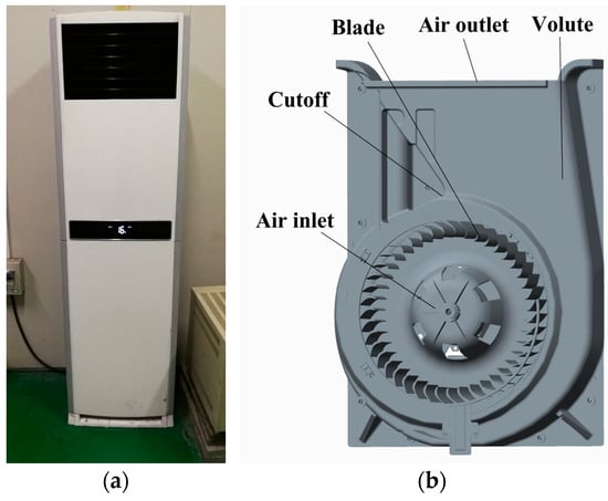
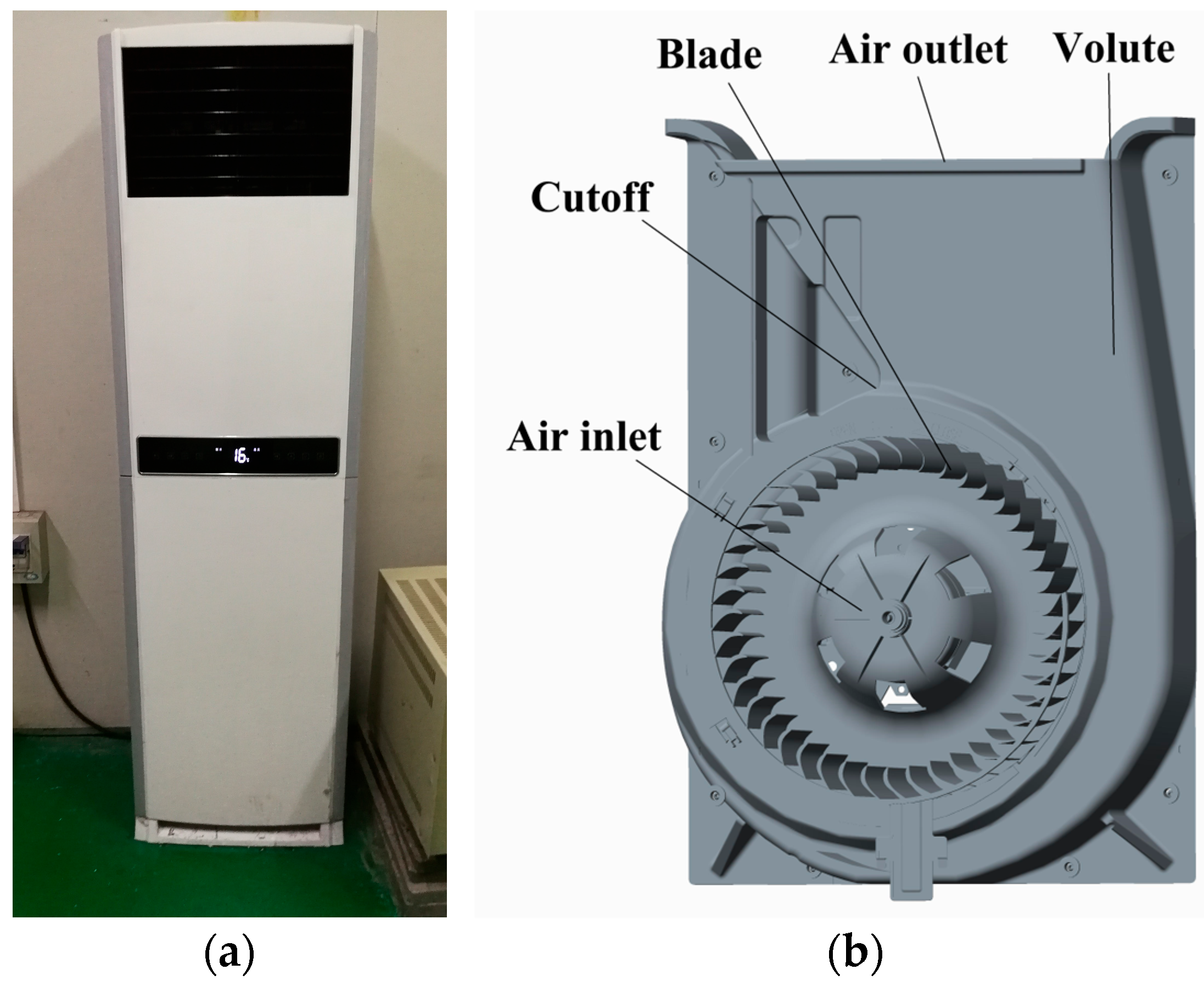
Under identical conditions, multi-blade centrifugal fans offer the advantages of a compact design, a small system footprint, and low noise levels. They are widely used in various low-pressure ventilation and air exchange applications, such as split-type floor-standing air conditioners, window-type air conditioners, and air purifiers, and serve as the primary equipment in indoor air conditioner units and fresh air heat exchange systems. The centrifugal fan system of an indoor air conditioner is shown in Figure 1.
Figure 1.
The physical and model diagram of the centrifugal fan of the indoor unit of the air conditioner: (a) indoor air conditioner; (b) multi-blade centrifugal fans.
3.1. Semi-Anechoic Laboratory
When noise signals are acquired in ordinary test facilities, interference such as reflection and diffraction from objects at the test site can cause distortion in the noise test results. To prevent this from occurring, accurate acquisition of noise signals must be conducted in an anechoic environment. To eliminate the effects of sound wave reflection and diffraction within the chamber and ensure that incident sound waves from the external environment are fully absorbed and dissipated within a specific frequency range, the interior wall structure of the anechoic chamber must incorporate vibration isolation and sound-absorbing designs. The interior surfaces—including walls and floors—must be lined with high-performance noise-reducing materials such as asbestos, fiberglass, and acoustic foam. Anechoic chambers are currently classified into two types: fully anechoic chambers and semi-anechoic chambers. In a fully anechoic chamber, all six surfaces of the room are lined with sound-absorbing and noise-reducing materials, whereas in a semi-anechoic chamber, only five or four surfaces are lined with such materials. The ambient background noise level in a semi-anechoic chamber is 18 dB, under the following environmental conditions: temperature 23 ± 2 °C, humidity 50 ± 10%.
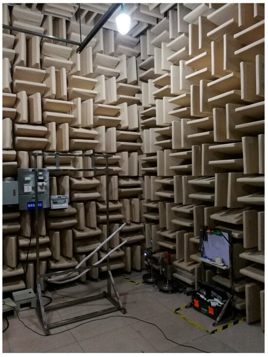
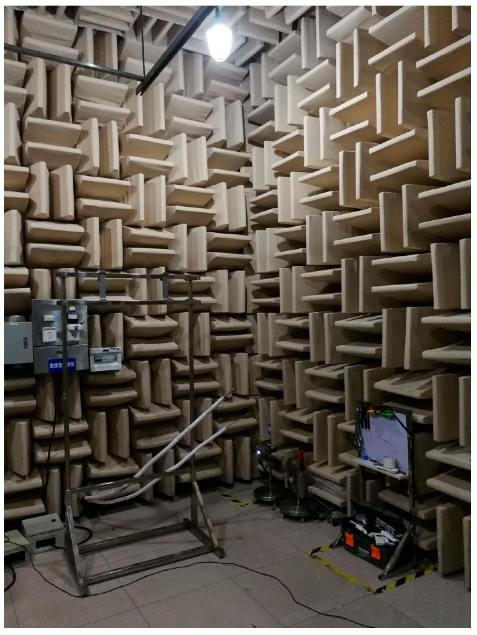
The fan arrangement follows the hemispherical method; with measurement points located on a hemisphere centered at the geometric center of the indoor unit and having a radius of R = 1 m; the base of the hemisphere is the floor of the semi-anechoic chamber. For air conditioners that are placed on the floor or mounted on a wall during use, testing is conducted in a manner consistent with the actual usage scenario: they are placed on the floor or mounted on specialized equipment within the semi-anechoic chamber to measure their noise characteristics. For testing the fan noise of air conditioners, the test data consists of the total A-weighted sound pressure level and the octave-band spectrum at the standard position. Noise measurements were conducted in accordance with the national standard GB/T 7725-2004 [24]. All noise and vibration data in this paper were collected in a semi-anechoic chamber, and the test environment met the requirements for air conditioner noise testing, as shown in Figure 2.
Figure 2.
Noise laboratory.
3.2. Noise Test System
The noise vibration test in this paper uses the noise acquisition system of Belgium LMS company, which can measure the noise source spectrum, sound intensity distribution and sound power level. The device is divided into a software system and a hardware system.
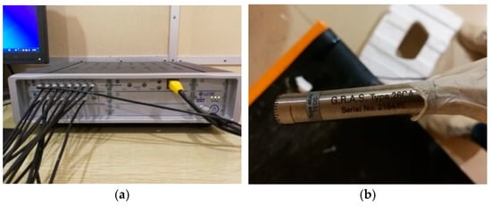
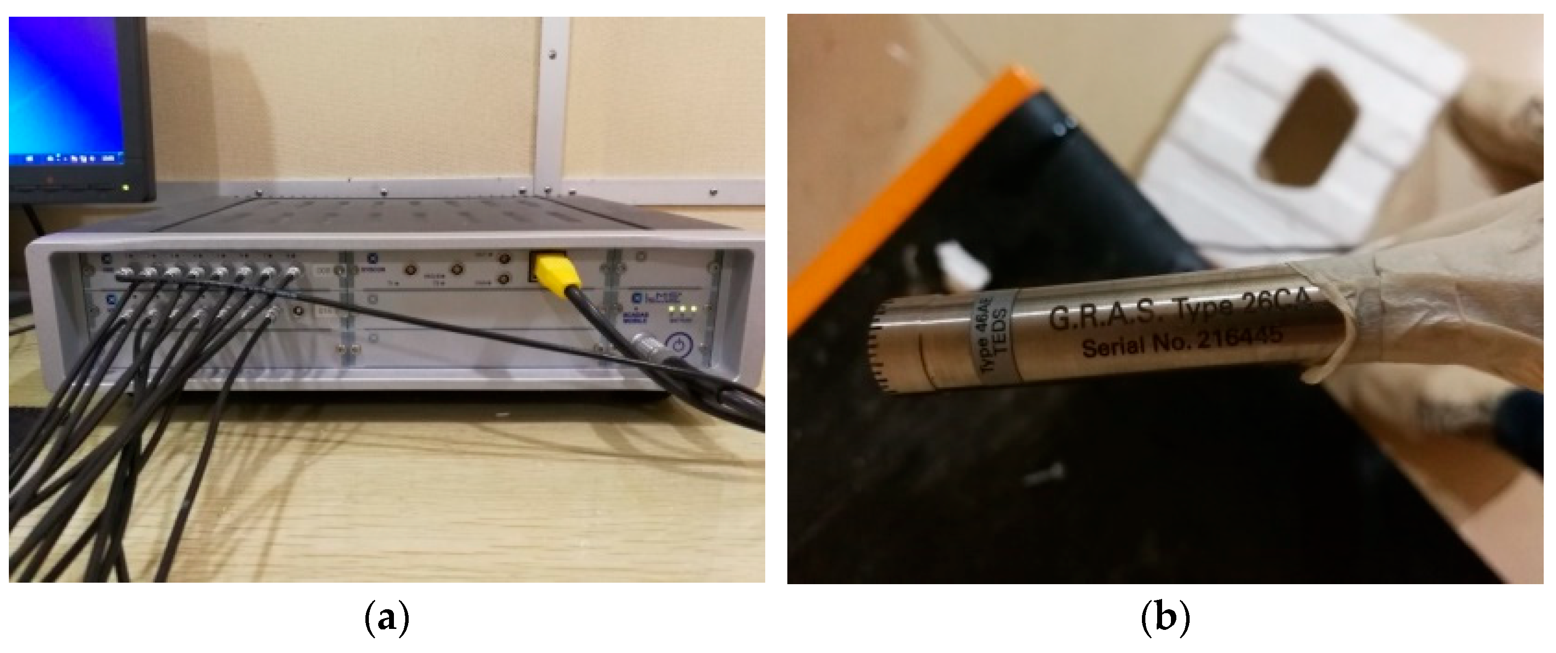
The hardware part of the noise test equipment is the LMS SCADAS Mobile, as shown in Figure 3a. The function of the hardware part of the device is the acquisition and transmission of noise data, and the transmitted noise signals are processed in the computer. Hardware equipment has 16 signal channels, with each channel’s sampling rate up to 102.4 kHz and a data transfer rate of 3.8 M sample points/s, and it can synchronize the acquisition of pressure pulsation, vibration, noise and other sources of dynamic signals. Noise test equipment signal acquisition uses the U.S. PCB company produced by the high-frequency loudness sensor. The series of high-frequency loudness sensor is characterized by high precision, high intrinsic frequency and wide temperature range, the measurement frequency range of 3.15 Hz–20 kHz, and the maximum measured sound pressure level of 146 dB; this frequency range is the standard specification for industrial-grade precision microphones and fully complies with the requirements of IEC 61672, Class 1 as shown in Figure 3b. This shows that the performance parameters are fully able to meet the needs of the air-conditioner fan test.
Figure 3.
Noise test equipment: (a) hardware part of the test equipment; (b) high-frequency sensor.
Noise test equipment software system works to display the dynamic signal data of the extracted noise source in real time. In this paper, the parameters of signal data acquisition settings are a sampling frequency of 6400 Hz and a total time of 30 s. The signal processing use of a low-pass filtering function can effectively avoid signal aliasing; the time-domain data of the noise signal using the Hanning window function to truncate the processing can effectively avoid signal omission, and the noise signal data can be tested under the conditions of Fast Fourier Transform (FFT) post-processing.
3.3. Noise Test Results and Analysis
To achieve impedance matching and precise frequency-domain alignment between the broadband noise characteristics of a micro-perforated silencer and an indoor centrifugal fan, this paper adopts a technical approach consisting of “frequency-domain identification of the noise source—boundary solution in the silencer domain—inverse design of structural parameters.” First, using a specific model of an indoor air conditioning unit as the test subject, noise spectra were collected for four fan speed settings under steady-state operating conditions. 1/3-octave band analysis and A-weighting correction were applied to extract characteristic frequency-domain features. Second, by comparing the spectral evolution patterns across the different fan speed settings, the effective noise attenuation frequency range that the micro-perforated silencer must cover was defined. Finally, based on this range, structural parameters (pore diameter, porosity, and rear chamber depth) were designed to match the requirements, and the noise reduction effectiveness was verified.
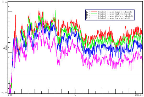
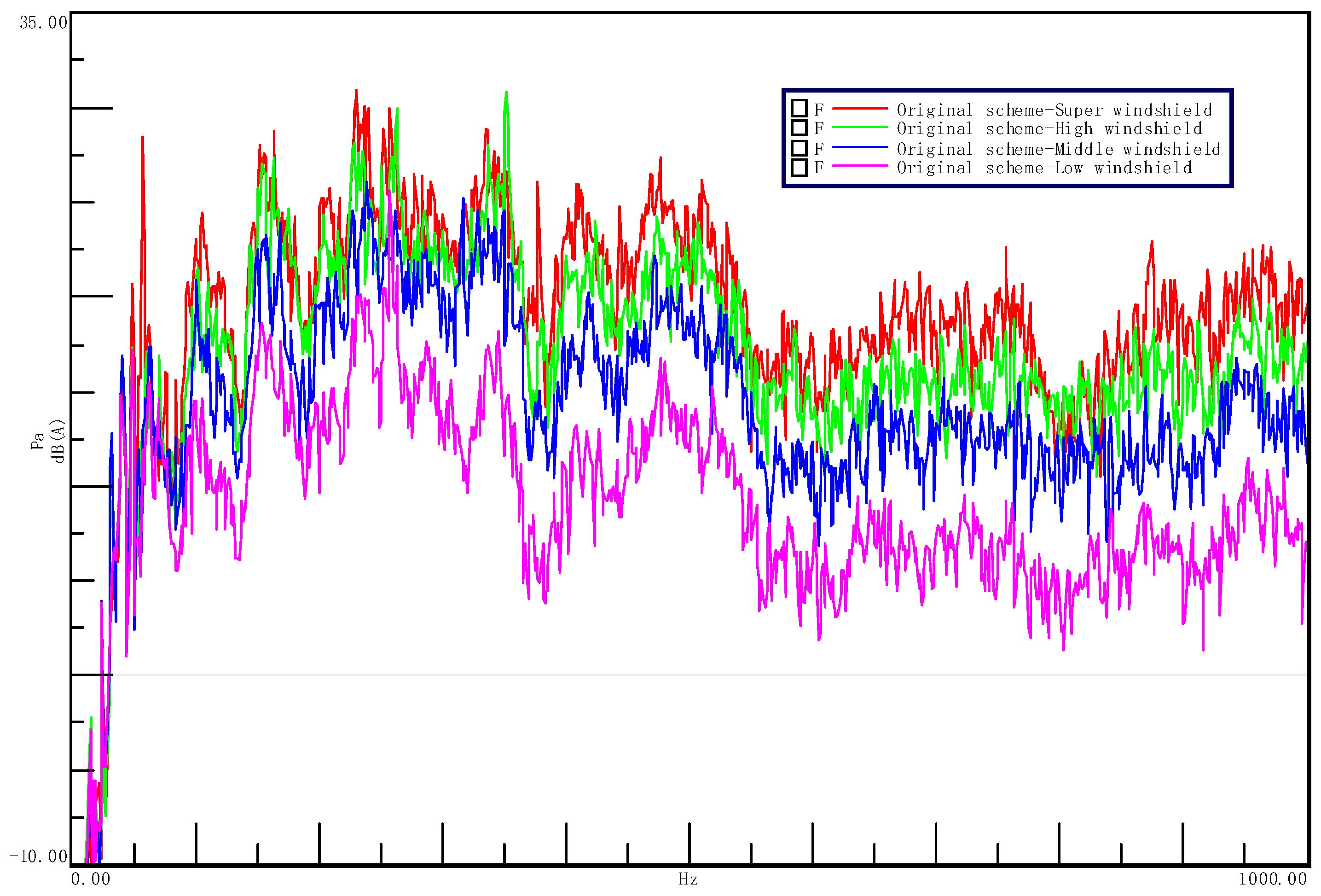
Spectral analysis shows (Figure 4) that the noise from each wind speed range exhibits a distinct broadband concentration in the low-to-mid frequency range: the main peak frequency is stable at f0 = 350 Hz, while the noise energy is concentrated in a relatively wide frequency band ranging from 100 Hz to 800 Hz (boundary frequencies: f1 = 100 Hz, f2 = 800 Hz), with an amplitude reaching up to 31 dB(A). This frequency range far exceeds the range covered by a single resonance frequency; therefore, this paper does not treat the micro-perforated silencer as a narrow-band resonator targeting only f0 but rather designs it as a sound-absorbing structure with multiple attenuation peaks distributed across the target frequency band [f1, f2] through coordinated multi-parameter control, thereby achieving distributed suppression of broadband noise peaks.
Figure 4.
Noise spectrum of the indoor unit at various fan speeds.
4. Structural Design of Micro-Perforated Silencers for Centrifugal Fans
4.1. Design Parameters for Micro-Perforated Silencers in Centrifugal Fans
Based on the detailed comparison of the spectra for each wind speed range in the previous section and the definition of frequency boundaries for noise attenuation, this section further translates the frequency-domain objectives into the physical structural parameters of the micro-perforated silencer. The design process follows the technical logic of “noise source frequency domain → identification of the noise attenuation range → inverse mapping of structural parameters.” The specific steps are as follows:
4.1.1. Determine f0 and Design the Cavity Depth D
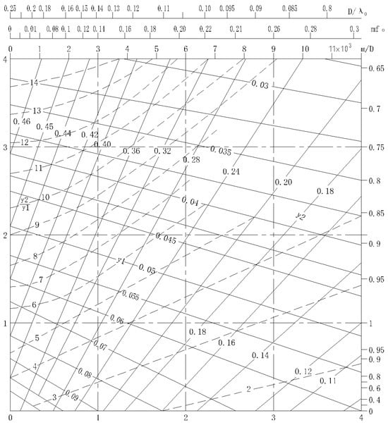
By plotting the relationships of the various parameters on a single graph using Equations (30)–(32) [5], Figure 5 was obtained.
Figure 5.
Graph showing the acoustic properties of micro-perforated plate structures.
Based on the previous analysis, that f2/f1 = y2/y1 = 8. Therefore, you need to find the curve where y2/y1 = 8. Select a point on the curve y2/y1 = 8 while ensuring the highest possible absorption rate. Draw perpendicular lines to obtain the intersection point a0= 0.914, r = 1.83, mf0 = 0.06, y0 = D/λ = 0.19, and m/D = 1.1. Therefore, m = 0.000171 and D = 171 mm. Find the lines where y1 and y2 intersect the selected point, yielding y1 = 0.053 and y2 = 0.42.
To further verify the accuracy of the data points, based on f0:f1:f2 = y0:y1:y2, we substituted the values into the formula and calculated f1 = 97.6 Hz and f2 = 773.7 Hz. Since these values differ only slightly from the target values, the requirements are met, and therefore no corrections will be made to the data.
4.1.2. Design Aperture d
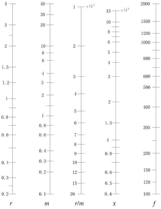
Given r, m, and f0, plot the points on the graph shown in Figure 6. Draw a line through two of the points; the line where it intersects the y-axis gives the values of x and r/m. Thus, we obtained x = 0.95 and r/m = 11,000.
Figure 6.
A chart to approximate the value of x.
Using the formula , substitute the values of x and f obtained earlier to calculate d = 0.24 mm; using the formula r/m = 1140/d2 × (kr/km), we obtained kr/km = 0.556.
4.1.3. Design Plate Thickness t
The acoustic impedance and acoustic mass are, respectively:
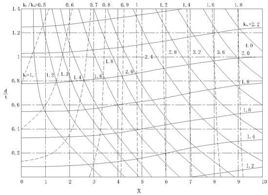
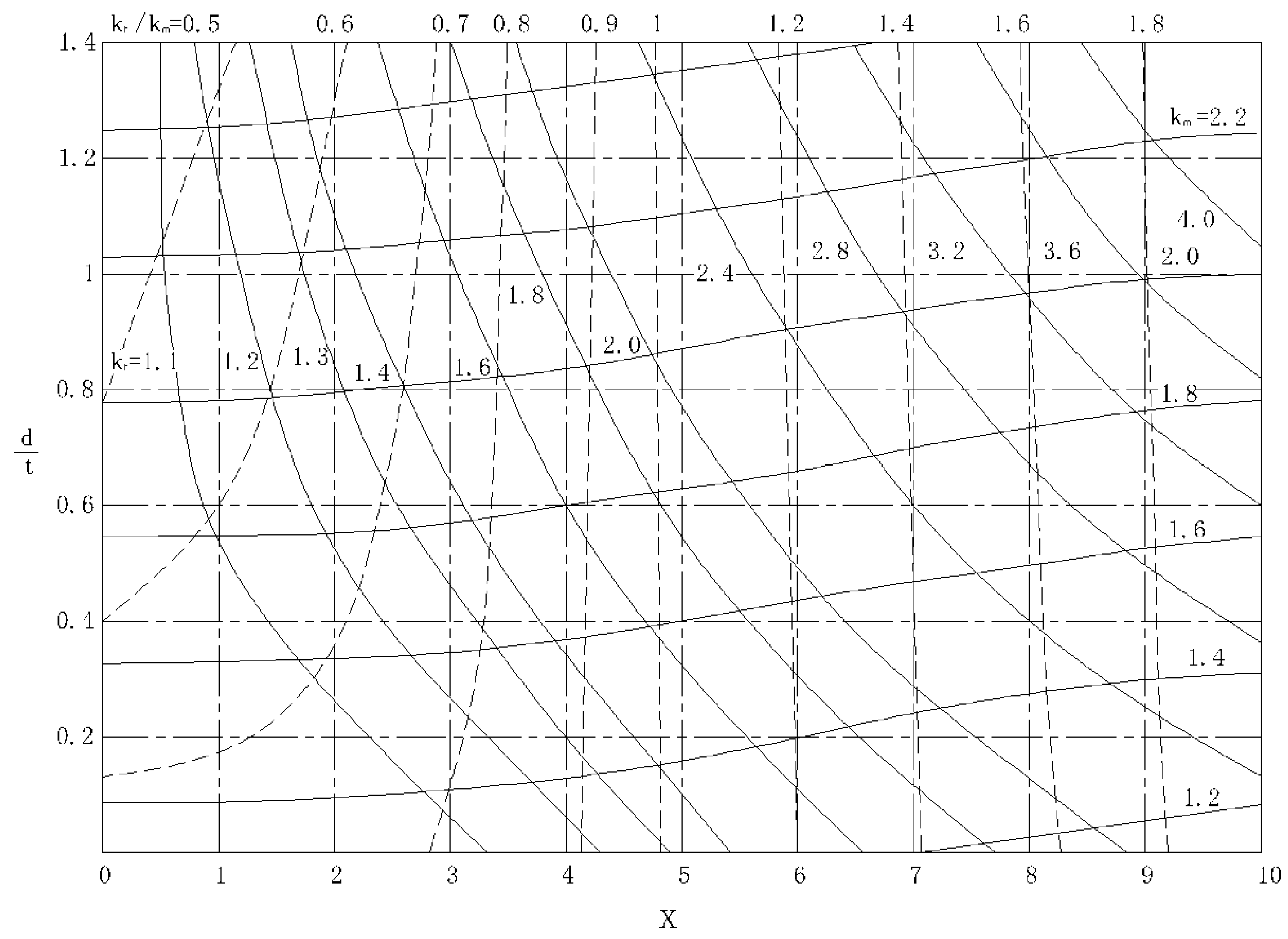
Figure 7 illustrates two core dimensionless parameters in the design of micro-perforated plates: the acoustic resistance constant and the acoustic quality constant. These parameters are key to understanding and designing the sound-absorbing performance of micro-perforated panels.
Figure 7.
Acoustic resistance constant and acoustic quality constant.
In the above equations: f represents frequency; r, x, kr, and km are all relative values (rational numbers); the unit of m is seconds, and when multiplied by ω, it becomes a rational number; kr and km are functions of x and d/t. Plotting the relationships between the variables based on Equations (33)–(36) yields the graph shown in Figure 7.
Given kr/km and x, select a point as shown in the figure. Draw a perpendicular line to find the point of intersection where d/t = 0.6, and then calculate t = 0.4 mm. At the same time, determine that kr = 1.1 and km = 1.82.
4.1.4. Calculate the Hole Spacing b
Using the formula , where km, m, and t are known, one can calculate p = 1.33. Substituting this value into the formula yields p = 78.5 d2/b2, so b = 1.92 mm.
At this point, the calculations for all parameters of the micro-perforated silencer-sheet thickness t, chamber thickness D, hole diameter d, and hole spacing b- were completed. Specifically, the calculated theoretical silencer parameters are D = 171 mm, t = 0.4 mm, d = 0.24 mm, and b = 1.92 mm.
4.1.5. Theoretical Value Correction
To optimize the design parameters of micro-perforated silencers, the theoretical design values should be adjusted as follows:
- (1)
- If the hole diameter calculated based on the frequency response is ≥1 mm, no adjustment is necessary;
- (2)
- If the hole diameter d is ≤1 mm, adjustments should be made using the example of d = 0.24 mm.
Since f0 and the theoretical frequency range remain unchanged, the parameters obtained in step 4.1.1 remain unchanged.
The theory of micro-perforated sound attenuation indicates that reducing the pore diameter d helps broaden the sound absorption bandwidth and improve the low-frequency sound absorption coefficient; however, the selection of pore diameter must simultaneously satisfy multiple engineering constraints. First, the perforated plate must have sufficient structural rigidity to withstand fluid-structure-coupled vibrations caused by high-speed airflow impacts within the fan volute, thereby preventing secondary noise induced by plate flutter. Second, the lower limit of the aperture size is constrained by manufacturing precision and long-term operational reliability—excessively small micro-holes are prone to clogging due to dust accumulation during long-term operation of the indoor unit, leading to drift in acoustic impedance characteristics and degradation of sound attenuation performance. Taking into account the three constraints of maximizing acoustic performance, ensuring structural reliability, and maintaining manufacturing feasibility, and in conjunction with the engineering recommendations in Reference [25], this paper revises the lower limit of the aperture diameter to d =1 mm as the minimum engineering-feasible feature size. Based on this, the matching values for the perforation rate p, the relative acoustic mass m of the perforated plate, and the relative acoustic resistance r/m are recalculated according to the mapping relationship in Section 4.1.2. Following the procedures in Section 4.1.3 and Section 4.1.4, the optimized plate thickness and hole spacing are determined iteratively, forming a closed-loop design correction mechanism of “theoretical optimum → engineering correction → parameter remapping.” It is particularly noteworthy that during the recalculation process, based on a multi-parameter linked recalculation using the value of k as a “constant,” the plate thickness (t: 0.5→1.2 mm) and perforation rate (p: 1.5%→3.8%) were recalculated to maintain the perforation constant at k ≈ 1.40 which is nearly identical to the theoretical value of 1.42 (deviation < 1.5%). Based on the actual available space in the indoor unit, the cavity depth was adjusted from 171 mm to 100 mm; this change primarily affects the fundamental resonance frequency. After recalibration, the theoretical resonance frequency remained at approximately 348 Hz, with a deviation of less than 1% from the target value of 350 Hz.
After completing the theoretical correction, the changes in the k values before and after the recalculation were analyzed; these parameters are shown in Table 1.
Table 1.
Comparison of k values before and after recalculation via linkage.
4.1.6. Theoretical Prediction of the Influence of Structural Parameters of Micro-Perforated Plates on Sound Absorption Performance
Based on the theoretical discussions by Wang Jing et al. [26] on global parameter sensitivity analysis and by Hu Peng et al. [27] on the acoustic performance of micro-perforated plate structures and the influence of various structural parameters (pore diameter, porosity, cavity depth, and panel thickness) on sound absorption performance, this paper presents a theoretical table that illustrates the expected impact of a single parameter change on sound absorption performance while holding other parameters constant, as shown in Table 2.
Table 2.
Patterns of the influence of structural parameters of micro-perforated panels on sound absorption performance (theoretical predictions).
4.2. Manufacturing of Micro-Perforated Silencers for Centrifugal Fans
The effective noise reduction frequency band of micro-perforated silencers is sensitive to perforation geometric parameters (hole diameter, hole spacing, and perforation rate) and therefore places high demands on machining precision. Given the structural characteristics of the curved silencing surface, this study employed a precision drilling process to machine the micro-holes in the prototype during the design verification phase—using custom positioning jigs to control the distribution of hole locations and high-precision drill bits to ensure consistency in hole diameter and surface finish. After machining, key dimensions were individually measured and inspected to ensure that the deviations between the measured values of hole diameter, hole spacing, and perforation rate and the design values fell within the tolerance window. ABS engineering plastic was selected as the base material. It ensures structural rigidity while offering good machinability and suitability for injection molding. Additionally, it is cost-effective and adaptable to various environmental conditions, meeting the comprehensive engineering requirements for home appliance components.
The fabrication of micro-perforated silencer prototypes follows a four-step process: “Digital Modeling → Machining Alignment → Precision Perforation → Component Assembly.” The specific process is as follows:
4.2.1. Modeling the Perforation Surface
Based on the spatial envelope at the spiral shell’s tongue and the developed dimensions of the silencer surface, a 3D surface model of the micro-perforation distribution is created in Creo modeling software to generate machining alignment benchmarks and reference for hole layout.
4.2.2. Hole Positioning and Calibration
Hole Positioning and Calibration: Using the numerical model from Step (1) as a reference and driven by the design-calculated parameters for hole diameter, hole spacing, and perforation rate, the relative coordinates of each micro-hole’s center point were calibrated on the actual machining surface. Positioning was performed by marking lines using a vernier caliper in conjunction with a height gauge to ensure that hole position deviations were controlled within the design tolerance range.
4.2.3. Precision Drilling and Component Forming
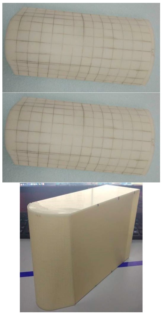
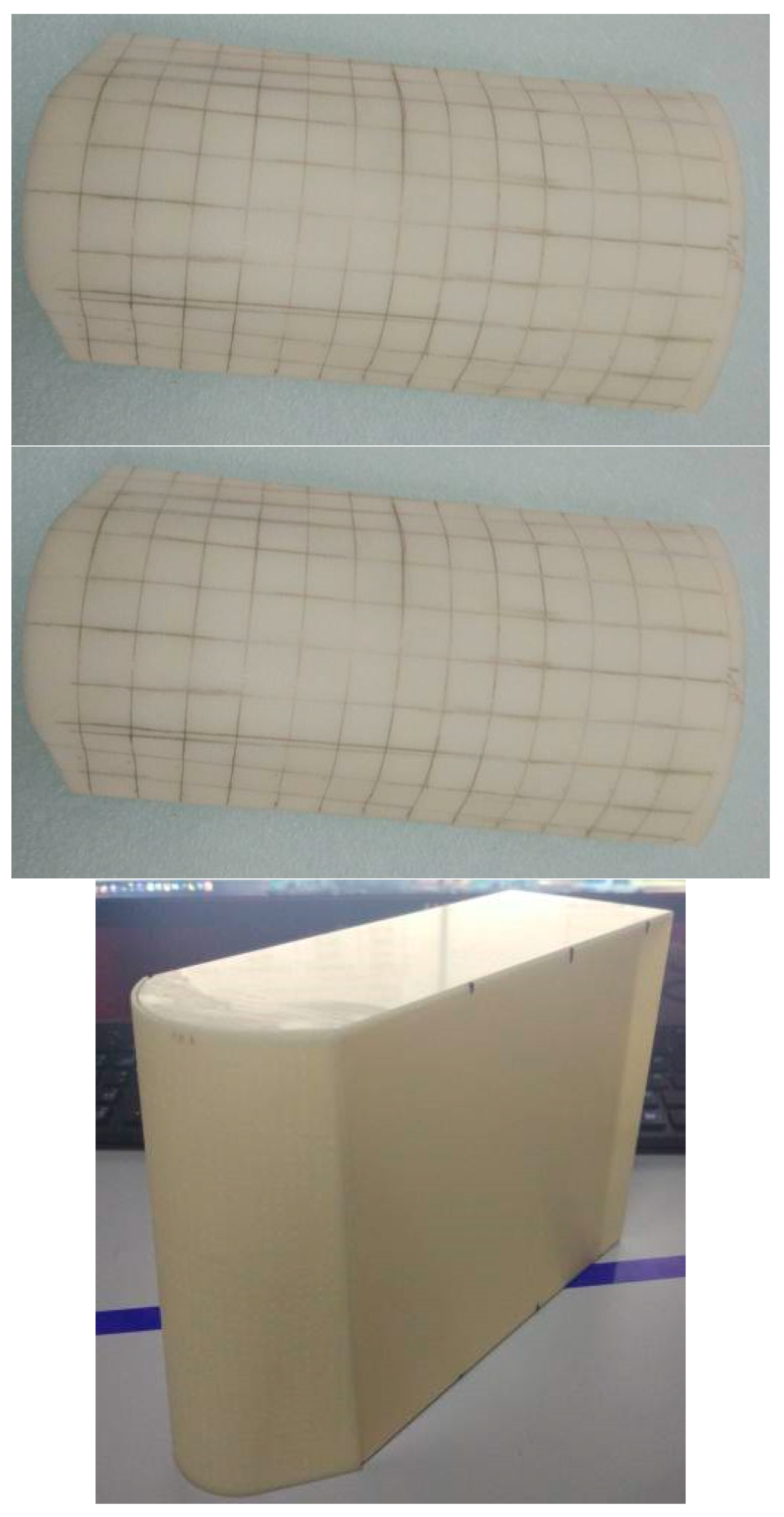
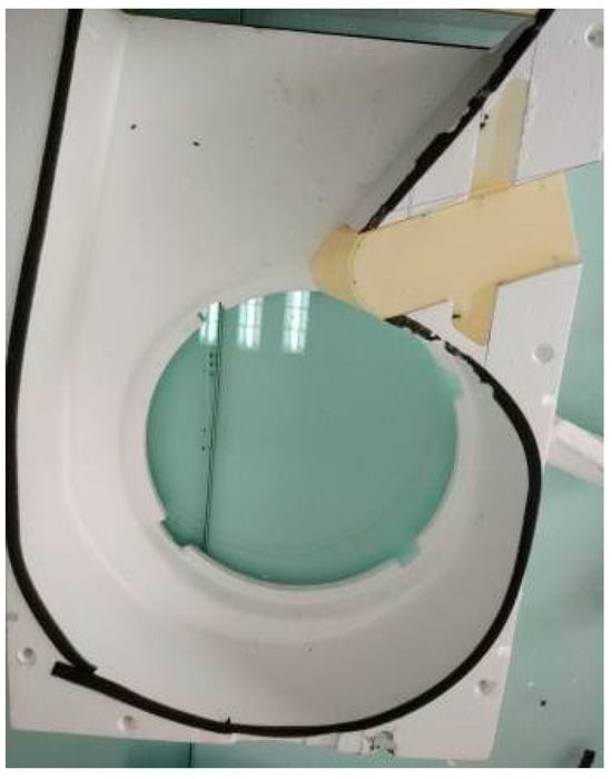
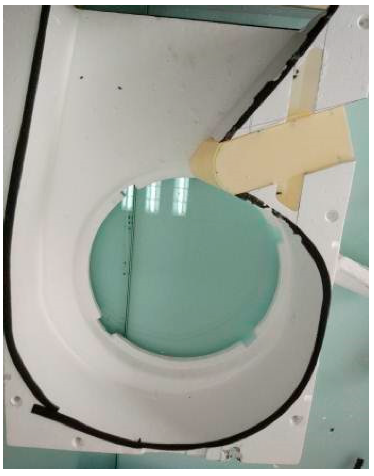
Engineering-grade precision drill bits of the appropriate specifications, selected based on the designed hole diameters, are used to drill the micro-holes one by one at the calibrated positions. After drilling, burrs on the hole walls are removed to ensure consistency in the surface finish of the perforated edges and the acoustic impedance characteristics. Subsequently, the micro-perforated silencing surface is bonded to the sealed rear cavity using a specialized ABS adhesive to form a complete micro-perforated silencing assembly (Figure 8). The bonding process must ensure the integrity of the joint to prevent sound leakage, which would reduce silencing efficiency.
Figure 8.
Photograph of a micro-perforated sound-absorbing chamber.
4.2.4. Assembly of the Complete Silencer
Based on the results of the numerical analysis of the internal flow field of the indoor unit’s multi-wing centrifugal fan and the frequency-domain sound absorption characteristics of the micro-perforated silencer, it was determined that the silencer assembly should be installed at the fan volute’s tongue—a region where unsteady flow separation and vortex pulsations are most intense within the fan, and which is also the primary source of broadband noise. The micro-perforated silencer assembly was embedded into the inner wall of the volute tongue. After installation, the clearance between the assembly and the surrounding structure was inspected to ensure that the original flow cross-section of the volute was not substantially compromised. The installation location is shown in Figure 9. The detailed parametric feature description of micro-perforated silencer are provided in the Appendix A.
Figure 9.
Photograph of the installed micro-perforated silencer on the volute tongue wall.
5. Analysis of the Absorption Bandwidth of Micro-Perforated Acoustic Panels
5.1. Airflow Performance Testing of Micro-Perforate d Silencers for Centrifugal Fans
To avoid the adverse effects of secondary phenomena caused by noise reduction measures on the fan’s aerodynamic performance, this study established “no degradation of aerodynamic performance” as a mandatory boundary condition for the design of micro-perforated silencers and conducted rigorous comparative tests between the original design and the micro-perforated design. Based on the numerical results of the flow field inside the indoor unit, it is evident that intense shear layer oscillations and periodic vortex shedding in the volute tongue region are the primary sources of broadband noise.
First, the micro-perforated plate forms a distributed micro-damped boundary on the wall of the spiral tongue—when unsteady flow passes over the micro-perforated surface, local micro-vortices at the edges of the apertures convert pulsating kinetic energy into thermal energy through viscous dissipation, thereby reducing the strength of the near-wall shear layer and the amplitude of pressure pulsations.
Second, the combined structure of the micro-perforated plate and the sealed rear cavity acts as a dynamic pressure buffer layer: pressure pulsations at the scroll tongue enter the rear cavity through the micro-perforations, where they undergo multiple reflections and dissipation; by the time they radiate back through the micro-perforations, the high-frequency components have been significantly attenuated.
Furthermore, the micro-perforation scale (millimeter level) is far smaller than the characteristic scale of the volute flow channel, and the wall-hugging arrangement of the rear chamber does not encroach on the main flow path; therefore, it causes virtually no substantial interference with time-averaged aerodynamic parameters (airflow and power). The synergistic mechanism of the aforementioned “scale separation” and “selective component damping” constitutes the physical basis for the micro-perforated silencing structure to achieve the decoupling of “noise reduction and performance preservation.”
The experimental data shown in Table 3 further quantitatively confirm that, across all fan speed ranges, the airflow and power of the micro-perforated design show virtually no deviation from the original design (deviation < 0.5%), and equivalent aerodynamic performance is maintained. This conclusion demonstrates the feasibility of this design in achieving the dual objectives of “aerodynamics and acoustics,” while also providing key design constraints for the engineering application of micro-perforated silencers within the compact spaces of household appliances.
Table 3.
Performance comparison of micro-perforated noise reduction.
5.2. Noise Performance Testing of Micro-Perforated Silencers for Centrifugal Fans
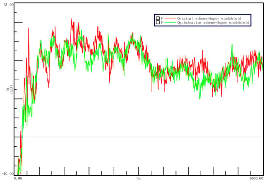
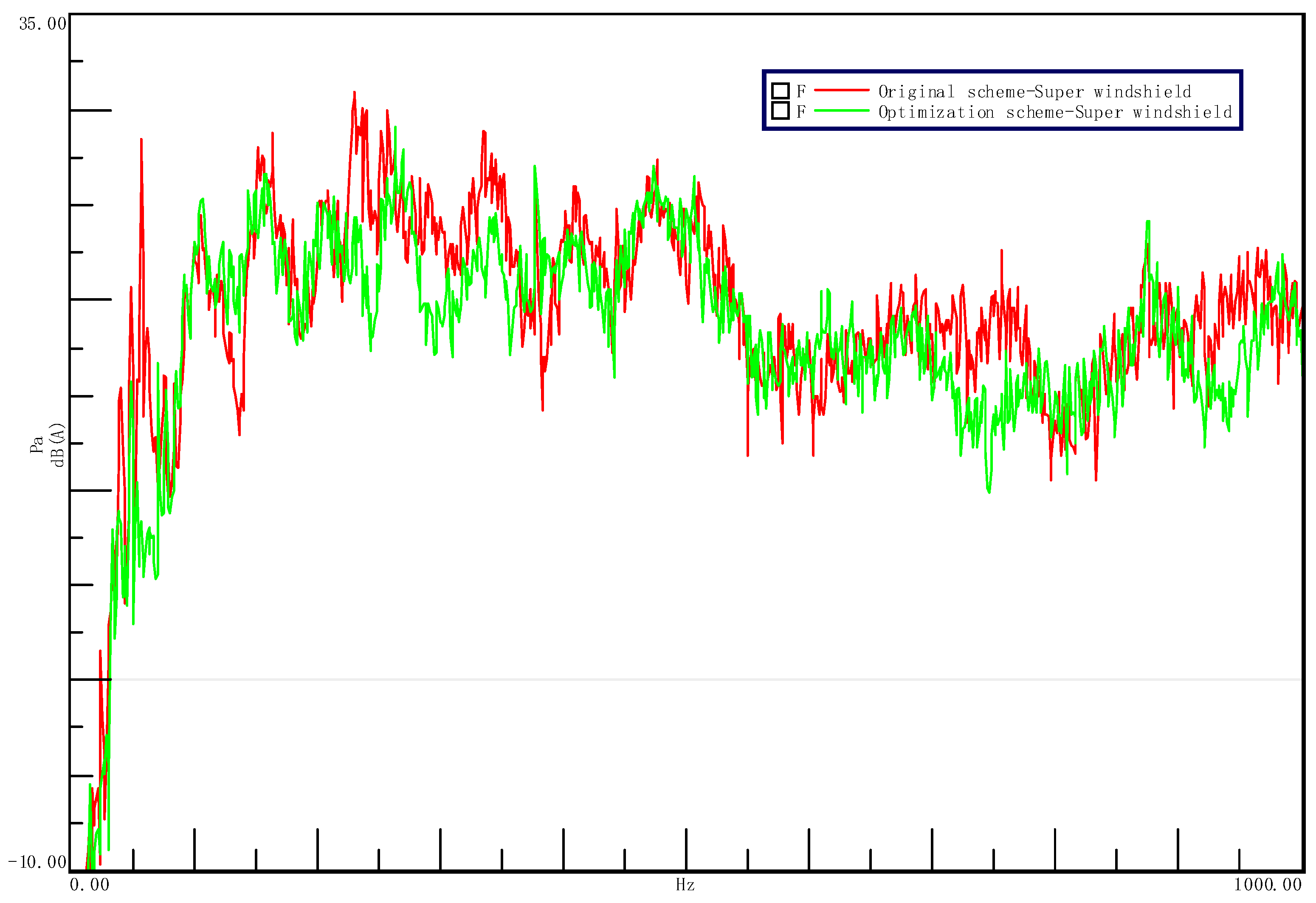
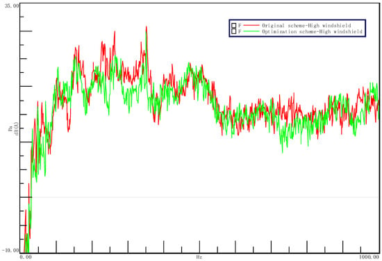
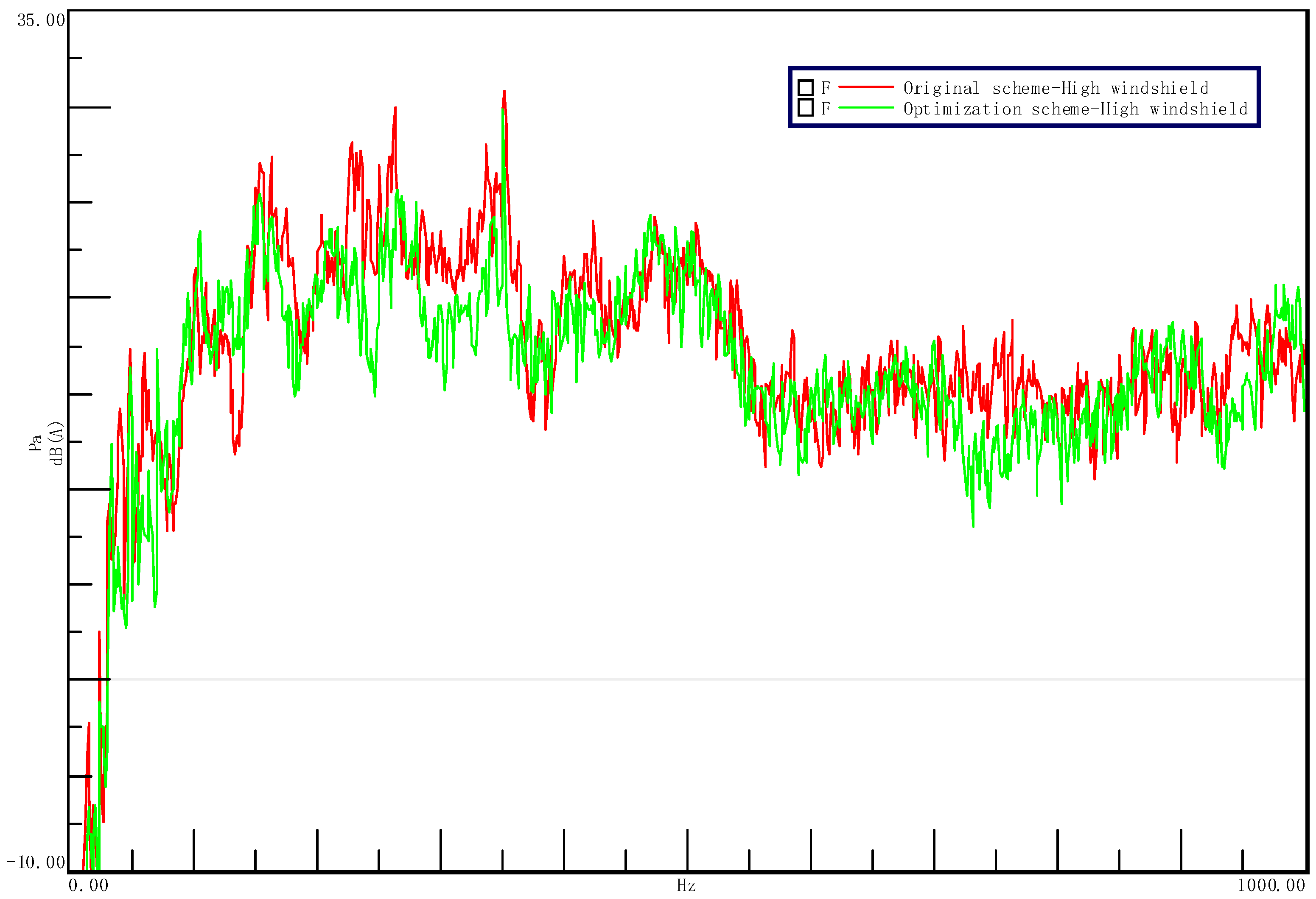
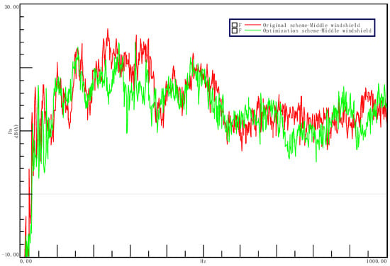
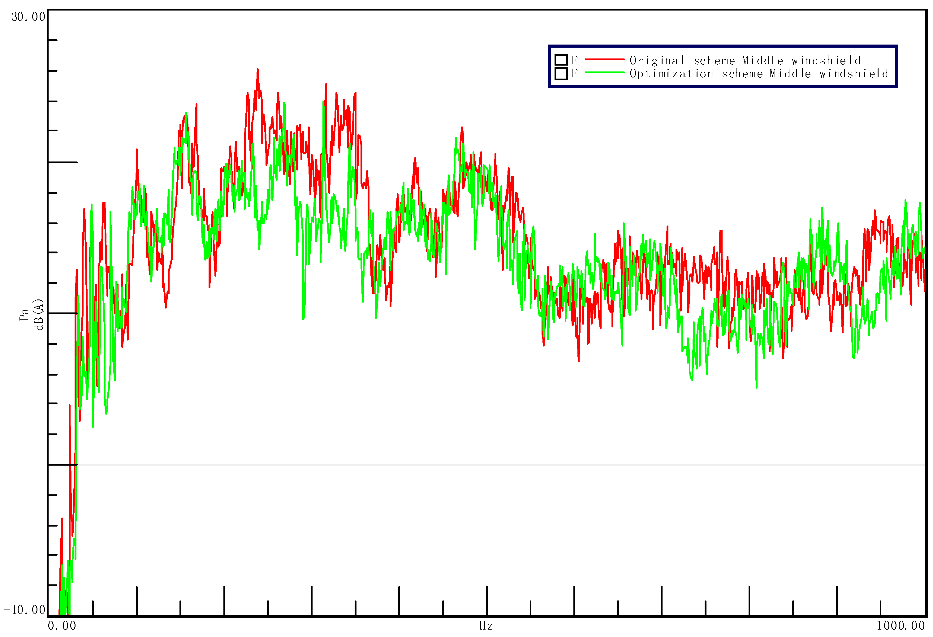
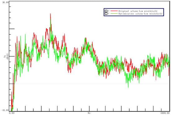
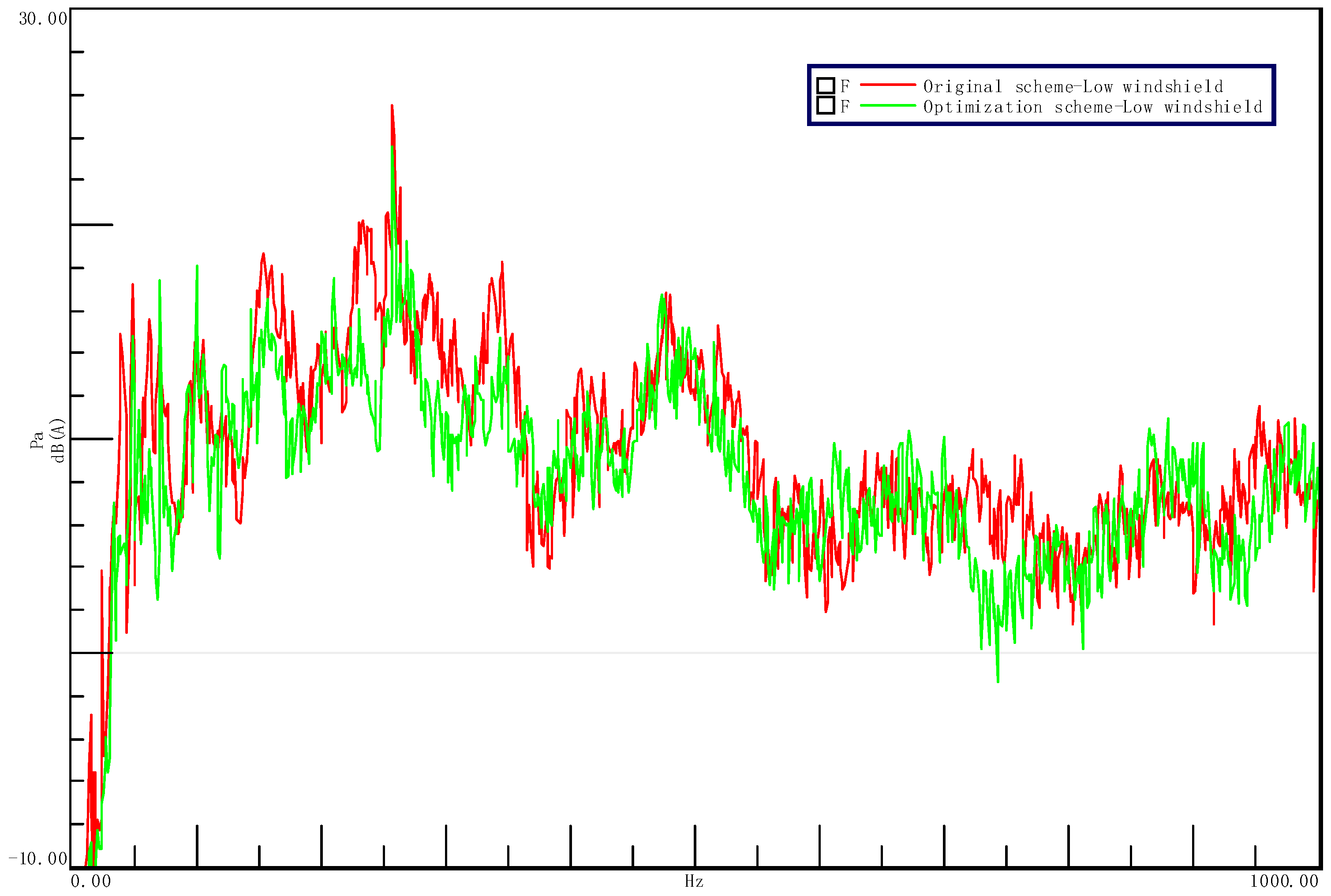
To quantitatively evaluate the noise reduction effectiveness of the micro-perforated silencer design, the noise spectra and total noise levels of the micro-perforated design were compared with those of the original design under various wind speeds (Table 4, Figure 10, Figure 11, Figure 12 and Figure 13). The test results indicate that:
Table 4.
Noise comparison of micro-perforated noise reduction solutions.
Figure 10.
Noise spectrum plot for the Super windshield.
Figure 11.
Noise spectrum plot for the High windshield.
Figure 12.
Noise spectrum plot for the Middle windshield.
Figure 13.
Noise spectrum plot for the Low windshield.
- (1)
- The noise reduction frequency bands closely align with the design objectives: The effective noise reduction frequencies for each fan speed setting are concentrated within two characteristic frequency bands—200–400 Hz and 700–800 Hz—which are essentially consistent with the target frequency ranges identified in the design calculations for the micro-perforated silencer. This validates that the “frequency-domain target-driven” design method proposed in this paper possesses high accuracy in predicting frequency response.
- (2)
- Noise reduction performance exhibits a trend of “better performance in the high-frequency range”: Under the “Strong,” “High,” and “Low” wind speed settings, noise peaks in both target frequency bands were effectively suppressed, and the spectral curves tended to flatten. The improvement was particularly significant in the 700–800 Hz band—peak reductions in this band were generally greater than those in the low-frequency band, and the amplitude of spectral line fluctuations was markedly reduced; the effective noise reduction range at the medium fan speed setting was further extended to 700–800 Hz, indicating that the micro-perforated structure maintains stable, broadband sound absorption capabilities even under varying operating conditions across multiple fan speed settings.
- (3)
- The “peak attenuation” effect far surpasses the “total reduction” effect: The total noise level across all wind speeds decreased by an average of 1 dB(A), while the average reduction in peak sound pressure reached 4 dB(A), with a maximum of 4.1 dB(A)—approximately four times the reduction in total noise level. This striking difference indicates that the mechanism of micro-perforated sound absorption is not uniform attenuation across the entire frequency band, but rather a “precision strike” targeting discrete noise peaks—that is, through micro-perforated resonant absorption, the acoustic energy originally concentrated at a few characteristic frequencies is effectively dissipated, causing the spectral structure to shift from a “multi-peak” profile to a “broadband flat” profile. This reshaping of the spectral profile is more significant for improving sound quality than a simple reduction in the total noise level.
6. Conclusions
Based on the broadband noise characteristics of centrifugal fans in air conditioners and the principle of micro-perforated silencers, this paper achieves targeted suppression of broadband noise and controllable spectral shape through the coupled optimization of key structural parameters such as pore diameter, porosity, and rear cavity depth. The main research conclusions are as follows:
- (1)
- Frequency-domain identification method: By comparing the 1/3-octave band spectra across different fan speed settings, the main peak frequency of the broadband noise from the indoor multi-blade centrifugal fan was determined to be 350 Hz, and the effective noise reduction frequency range was identified as 100–800 Hz, with 200–400 Hz and 700–800 Hz representing two distinct noise peak clusters—the latter showing a greater reduction in peak levels within the 700–800 Hz range than the former, attributable to the noise in this band being more concentrated at discrete frequencies, resulting in higher matching efficiency with the micro-perforated resonance absorption mechanism.
- (2)
- Parametric design method: A reverse mapping calculation chain was established: “target frequency range → resonance frequency → structural parameters.” Based on Ma Dayou’s theory, the resonant fundamental frequency was controlled by the rear cavity depth (D = 30 mm → f0 ≈ 350 Hz), and the sound absorption bandwidth was regulated by a combination of aperture diameter and perforation rate (d = 1.0 mm, p = 3.8% → k ≈ 1.40), with the effective sound absorption bandwidth covering 100–800 Hz. When the aperture diameter was adjusted from the theoretically optimal value of 0.24 mm to the engineering-feasible value of 1.0 mm, a recalculation was performed by adjusting both the plate thickness (0.5 → 1.2 mm) and the perforation rate (1.5% → 3.8%) in tandem. This maintained the perforated plate constant, ensuring that the theoretical sound absorption frequency band remained unchanged.
- (3)
- Aerodynamic–Acoustic Co-Verification: The wall-mounted installation of the micro-perforated silencer at the spiral tongue did not alter the flow cross-section of the spiral casing. The airflow and power measured at each test stage showed no significant changes compared to the original design (deviation < 0.5%), verifying that the synergistic mechanism of “distributed micro-damped boundaries” and “scale separation of the main flow channel” can achieve decoupling between noise reduction and performance preservation.
- (4)
- Noise Reduction Effect and Mechanism: The total noise level across all wind speeds was reduced by an average of 1 dB(A), and the peak sound pressure level was reduced by an average of 4 dB(A), with a maximum reduction of 4.1 dB(A). The peak reduction is four times that of the total reduction, indicating that the core mechanism of this method is “frequency-selective resonant absorption”—that is, by precisely matching the resonance frequency of the micro-perforations with the peak frequency of the target noise, energy is dissipated directionally within a specific frequency band rather than uniformly across the entire frequency spectrum. The noise reduction effect in the 700–800 Hz frequency band is superior to that in the 200–400 Hz band, which is related to the sound absorption coefficient in this frequency band being closer to the theoretical peak.
- (5)
- Engineering Applicability: This study provides a quantifiable design process consisting of “spectral identification → parameter mapping → prototype validation.” This method is not dependent on specific fan models; its core logic—determining the boundaries of the noise attenuation frequency domain based on noise spectrum characteristics and then reverse-mapping them to structural parameters—has universal reference value across different fan types and application scenarios and offers engineering insights for low-noise design in home appliances, HVAC systems, and small rotating machinery.
- (6)
- Limitations of the Method and Directions for Future Research: (1) The parameter design was based on Ma Dayou’s theory, which assumes still air, and did not account for the effect of skimming flow at the spiral tongue on acoustic impedance. (2) Due to limitations in the manufacturing cost of the test specimens, single-variable control groups and hole-free control groups were not established for each condition. (3) No psychoacoustic experiments were conducted, and quantitative evidence for improvements in sound quality remains insufficient. Future research could explore the following directions: (1) Introduce a model to correct for skimming flow impedance. (2) Conduct experiments with controlled variables and hole-free control experiments. (3) Introduce multi-objective optimization algorithms. (4) Conduct psychoacoustic experiments.
Author Contributions
Conceptualization, W.Z.; methodology, W.Z.; validation, W.Z. and Y.Y.; formal analysis, Y.Y.; investigation, Y.Y.; resources, Y.Y.; data curation, W.Z.; writing—original draft preparation, W.Z.; writing—review and editing, W.Z.; visualization, Y.Y.; supervision, W.Z.; project administration, Y.Y. All authors have read and agreed to the published version of the manuscript.
Funding
The authors declare that this study received no financial support from any grant programs, research funding, or collaborating institutions; there are no conflicts of interest related to funding; and all research expenses were borne by the authors themselves.
Data Availability Statement
The datasets used and/or analyzed during the current study are available from the corresponding author on reasonable request.
Conflicts of Interest
The authors declare no conflict of interest.
Appendix A. Parametric Feature Description of Micro-Perforated Silencer
| Geometric/Parametric Features | Values/Descriptions | Remarks |
| Installation Area | Inner Surface of the Cam | Fits Tightly Against the Cam’s Curved Surface |
| Unfolded Panel Shape | Rectangle with rounded corners | Matches the volute envelope surface |
| Unfolded Dimensions (Length × Width) | 160 mm × 80 mm | Covers the main noise radiation area of the latch |
| Effective sound-absorbing area | Approximately 98 cm2 | Excluding the edge sealing area |
| Perforation Boundaries | No holes within 5 mm of the edge of the developed surface | To ensure structural sealing and strength |
| Pore size (d) | 1.0 mm | Meets processing, clogging prevention, and stiffness requirements |
| Perforation Rate (p) | 3.8% | Arranged uniformly in a square pattern |
| Hole Spacing (Center-to-Center Distance) | 4.8 mm | Determined by calculating the perforation rate and hole diameter |
| Hole Arrangement | Uniform Square Pattern | Facilitates machining and consistency control |
| Depth of the rear cavity (D) | 100 mm | Available space between the indoor unit’s volute and the outer casing |
| Sheet Thickness (t) | 1.2 mm | Ensures structural rigidity under high-speed airflow |
| Sealing Method | ABS-Specific Adhesive | Ensures an acoustic seal and prevents sound leakage |
| Mounting Method | Adhesive + Positioning Grooves on the Inside Wall of the Volute | Does not encroach on the volute’s flow cross-section |
References
- Maa, D.Y. Potential of micro perforated panel absorber. J. Acoust. Soc. Am. 1998, 104, 2861–2866. [Google Scholar]
- Maa, D.Y. Micro perforated panel wide bane absorbers. Noise Control Eng. J. 1987, 20, 77–84. [Google Scholar]
- Fang, D.; Wang, W.; Sun, J. Noise Control; Beijing Publishing House: Beijing, China, 1986. [Google Scholar]
- Maa, D.Y. Theory and Design of Micro-Perforated Panel Sound-Absorbing Structures. Sci. Sin. 1975, 38, 38–50. [Google Scholar]
- Dah-You, M.A.A. General theory and design of microperforated-panel absorbers. Acta Acust. 1997, 22, 385–393. [Google Scholar]
- Jiao, F.L.; Liu, K. Structural characteristics of micro perforated panel absorber under utmost frequency band condition. In Proceedings of the 10th International Congress of Sound and Vibration, Stockholm, Sweden, 7–10 July 2003. [Google Scholar]
- Liu, Z.; Yuan, J.; Chen, W.; Jian, S. Analysis and Optimization of acoustic absorption characteristics for composite micro-perforated panel absorbers. Tech. Acoust. 2021, 40, 515–520. [Google Scholar]
- Wu, F.; Chen, W.; Ju, Z.; Gu, Q.; Xiao, Y.; Yu, D.; Wen, J. Research on Frequency Broadband Sound Absorption Metamaterial Based on Combined Micro-Perforated Plate. Mater. China 2021, 40, 29–33+20–21. [Google Scholar]
- Gao, N.; Hong, H. Experimental investigation of sound ab-sorption in a composite absorber. Theor. Appl. Mech. Lett. 2021, 11, 100221. [Google Scholar] [CrossRef] [Scilit]
- Zuo, S.; Long, G.; Wu, X.; Xiang, L.; Zhang, M.; Hu, J. Resonant Frequency Predicting Model for a micro-perforated tube muffler considering its structural parameters. J. Vib. Shock 2015, 34, 173–178. [Google Scholar]
- Zhang, W.; Li, L.; Lyu, H.; Chen, L.; Ye, J.; Ma, Z. Research On Resonant Frequency Prediction Method of Microperforated Tube. China Meas. Test. 2022, 48, 18–22. [Google Scholar]
- Dah-You, M.A.A.; Ke, L. Sound Absorption Characteristics Of Microperforated Absorber For Random Incidence. Acta Acust. 2000, 25, 289–296. [Google Scholar]
- Nocke, C.; Liu, K.; Maa, D.Y. Statistical absorption of coefficient of microperforated absorbers. Chin. J. Acoust. 2000, 19, 97–104. [Google Scholar]
- Maa, D.Y. Microperforated Panel At High Sound Intensity. Acta Acust. 1996, 21, 257–262. [Google Scholar]
- Raffque, F.; Gong, C.; Song, S.; Lu, W.; Wu, Y.; Yang, F. Designing and experimental validation of single-layer mixed foil resonator acoustic membrane to enhance sound transmission loss (STL) within low to medium frequency range. Appl. Acoust. 2024, 219, 109930. [Google Scholar] [CrossRef] [Scilit]
- Gong, C.; Raffque, F.; Yang, F. Broadband Sound Insulation Enhancement Using Multi-Layer Thin-Foil Acoustic Membranes: Design and Experimental Validation. Appl. Sci. 2025, 15, 9279. [Google Scholar] [CrossRef] [Scilit]
- Rafque, F.; Wu, J.H.; Waqas, M.; Lushuai, X.; Ma, F. A thin double-layer multiple parallel-arranged inhomogeneous microperforated panel absorber for wideband low-frequency sound absorption. J. Braz. Soc. Mech. Sci. Eng. 2022, 44, 31. [Google Scholar] [CrossRef] [Scilit]
- Rafque, F.; Wu, J.H.; Naqvi, S.M.A.; Ma, F. Enhanced wideband low-frequency sound absorption of a single-layer multiple parallel-arranged inhomogeneous microperforated panel absorber. Acoust. Aust. 2021, 50, 49–69. [Google Scholar] [CrossRef] [Scilit]
- Rafique, F.; Wu, J.H.; Naqvi, S.M.A.; Waqas, M.; Liu, C.R. Extremely effective broadband low frequency sound absorption with inhomogeneous micro-perforated panel (iMPP) backed with spider-web designed cavities. J. Mater. Des. Appl. 2023, 237, 843–858. [Google Scholar] [CrossRef] [Scilit]
- Wu, J.H.; Liu, C.R.; Rafique, F.; Ma, F. Low-Frequency Sound Absorption of an Inhomogeneous Micro-Perforated Panel with J-Shaped Cavities of Different Depths. Acoust. Aust. 2022, 50, 203–214. [Google Scholar] [CrossRef] [Scilit]
- Wu, Y.; Huang, Z.; Zhang, J.; Zhang, X. Grouting defect detection of bridge tendon ducts using impact echo and deep learning via a two-stage strategy. Mech. Syst. Signal Process. 2025, 235, 112955. [Google Scholar] [CrossRef] [Scilit]
- Peng, W. Deign the Muffler of Microperforated Pane. In Proceedings of the 2012 China Household Appliance Technology Conference, Nanjing, China, 31 October–1 November 2012. [Google Scholar]
- Rayleigh, L.; Nachtrieb, N.H. The theory of sound. Phys. Today 1957, 10, 32–34. [Google Scholar] [CrossRef] [Scilit]
- GB/T 7725-2004; Room Air Conditioners. Standardization Administration of the People’s Republic of China: Beijing, China; China Standards Press: Beijing, China, 2004.
- Ke, L. Advance in the study of microperforated-panel and micro-slit acoustic absorbers. J. Appl. Acoust. 2002, 21, 3–6. [Google Scholar]
- Wang, J.; Li, J.Z.; Zhang, X.Z.; Bi, C.X. Global parameter sensitivity analysis of sound absorption performance of micro-perforated panels. J. Vib. Eng. 2025, 38, 1. [Google Scholar] [CrossRef]
- Hu, P.; Mao, G.P.; Zhao, X.D. Effects of structure parameters on the sound absorption of micro-perforated panel absorber. Piezoelectr. Acoustoopt. 2013, 35, 624–627+630. [Google Scholar]

Disclaimer/Publisher’s Note: The statements, opinions and data contained in all publications are solely those of the individual author(s) and contributor(s) and not of MDPI and/or the editor(s). MDPI and/or the editor(s) disclaim responsibility for any injury to people or property resulting from any ideas, methods, instructions or products referred to in the content. |
© 2026 by the authors. Licensee MDPI, Basel, Switzerland. This article is an open access article distributed under the terms and conditions of the Creative Commons Attribution (CC BY) license.