


Abstract
Parallel robots are widely applied in many fields because of their unique advantages. To ensure their operational safety and reduce maintenance costs, designing an accurate and reliable fault diagnosis method is essential. Focusing on the 2RRU-RRS parallel robot, this paper proposes an intelligent fault diagnosis method based on a multi-scale convolutional residual network integrated with an Efficient Channel Attention mechanism (MS-ECA-ResNet). Firstly, to fully retain the time-frequency features of the signals, the one-dimensional vibration signals are converted into two-dimensional images using the Continuous Wavelet Transform (CWT). Secondly, a multi-scale convolutional feature extraction structure is designed to enhance the model’s feature extraction ability at different time scales. Furthermore, the ECA mechanism is introduced into the residual network to reinforce important feature channels and suppress noise interference. Comparative experiments, noise environment experiments, and ablation experiments were conducted on a 2RRU-RRS parallel robot experimental platform with a vibration signal dataset. The results demonstrate that the proposed method achieves superior diagnostic accuracy and robustness compared to typical deep learning models, particularly in maintaining high performance under simulated noise conditions. This provides a preliminary validation of the method’s effectiveness in capturing fault-related impacts, offering a potential technical reference for the health monitoring of parallel robots in real-world scenarios.
1. Introduction
Parallel robots are widely used as core execution units in modern high-end manufacturing systems owing to their high load-bearing capacity and rapid response [1,2]. Compared to serial robots, these systems typically consist of multiple kinematic limbs with similar structures and motion characteristics. Their geometric layout and dynamic characteristics exhibit a high degree of spatial symmetry [3]. Such symmetry contributes to high motion accuracy and favorable dynamic performance. However, this symmetric structure introduces significant system coupling. The failure of a single joint or transmission component propagates through the multi-chain structure, causing complex nonlinear dynamic responses [4]. In practical applications, parallel robots often operate under complex or harsh conditions. With prolonged service, the operational reliability of the equipment gradually degrades, thereby affecting the motion accuracy of the robots and, in severe cases, leading to equipment downtime or even permanent damage. Therefore, developing effective condition monitoring methods is crucial for parallel robots to ensure reliable operation and avoid potential economic losses [5,6].
For fault diagnosis in mechanical systems, existing approaches can be broadly classified into model-based methods and data-driven methods [7,8,9]. For example, Masoumi et al. [10] introduced a fault diagnosis strategy based on the state-space model of a synchronous generator, coupling subspace identification with eigenvalue analysis to achieve fault detection and parameter estimation. Similarly, Niu et al. [11] proposed a model-driven diagnostic method for short-circuit faults in elevator traction systems. The method integrates an improved nonlinear unknown input observer, which is combined with least squares estimation, for the identification of stator winding inter-turn short-circuit faults. However, model-based fault diagnosis methods generally require an accurate system dynamic model and the construction of observer residuals, and their diagnostic performance is strongly dependent on the modeling accuracy and observer design. For multi-degree-of-freedom, strongly coupled nonlinear mechanical systems such as parallel robots, it is often difficult to establish an accurate dynamic model. Consequently, model uncertainties and parameter perturbations can significantly undermine the reliability of the diagnostic outcomes.
In contrast, data-driven methods overcome the limitations of relying on precise physical models. Instead, they monitor system health through data mining and feature extraction from sensor-collected data [12,13,14]. Benefiting from the rapid development of sensor and computer technologies, many excellent deep learning algorithms have been widely applied in the field of mechanical system fault diagnosis, such as Convolutional Neural Network (CNN) [15,16,17], Recurrent Neural Network (RNN) [18,19,20], Residual Neural Network (ResNet) [21,22,23], and Transformer [24,25]. Specifically, Zhang et al. [26] addressed the problem where industrial robot status information is complex and a single sensor cannot reflect system health. They proposed a fault diagnosis method based on multi-source data fusion and channel attention CNN. By fusing multi-sensor information and enhancing key features, they improved fault recognition accuracy under complex conditions. To address signal non-stationarity, Li et al. [27] aimed at the strong non-stationarity of vibration signals and proposed a variational mode decomposition-bidirectional long short-term memory (VMD-BiLSTM) fault diagnosis method. This method uses VMD to decompose original signals to enhance fault features and model temporal information through BiLSTM, achieving high-precision fault type identification in complex conditions. Gu et al. [28] introduced an improved Ghost-ResNet network that takes GADF-transformed two-dimensional images as input, effectively preserving the temporal correlation of time series and maintaining robust diagnostic performance under heavy noise. Additionally, Dai et al. [29] addressed the issues that traditional signal decomposition parameters rely on empirical selection, and single deep learning models struggle to balance local impact features and long-term dependencies. They proposed a bearing fault diagnosis method combining particle swarm optimization-based VMD (PSO-VMD) with a hybrid network consisting of a Transformer, a CNN, and a bidirectional gated recurrent unit (GRU). This method achieves adaptive selection of VMD parameters through PSO and combines the advantages of deep learning models like Transformer and CNN to enable accurate identification of bearing fault types.
The brief review above demonstrates that intelligent fault diagnosis based on data-driven methods has advanced rapidly and seen broad application [30,31,32]. Although these studies have achieved remarkable results, there are still some limitations. For instance, complex working conditions and noisy environments cause fault features to be easily obscured, weakening the fault discrimination ability of deep learning models. In addition, existing deep learning methods for mechanical fault diagnosis typically rely on single-scale convolutions or fixed receptive fields, limiting their ability to capture fault signatures across multiple time scales and frequency bands. Furthermore, existing attention mechanisms mostly act on channel or spatial information of single-scale features, lacking deep integration with the multi-scale feature extraction process. To improve model diagnostic performance in complex and noisy environments, Wang et al. [33] proposed a fault diagnosis method based on progressive hypergraph structure learning. This method models high-order associations between multiple sensor nodes through hypergraph structures, improving the noise robustness of the model. Long et al. [34] aimed at the problems of strong noise and complex spatial associations in industrial robot fault diagnosis and proposed a multi-scale convolutional capsule network, improving fault discrimination performance by introducing multi-scale feature fusion. Similarly, to address the inconsistent feature distribution under variable working conditions, Tang et al. [35] proposed an attention-based domain adaptation fault diagnosis method, achieving fault feature enhancement by introducing the simple attention module (SimAM).
Motivated by the aforementioned limitations, this paper investigates fault diagnosis of a 2RRU-RRS (R: revolute joint, U: universal joint, S: spherical joint) parallel robot [36] and proposes a fault diagnosis method based on a Multi-scale Efficient Channel Attention Residual Network (MS-ECA-ResNet). First, considering the pronounced non-stationarity and transient impact characteristics of the vibration signal in parallel robots, the continuous wavelet transform (CWT) is employed. One-dimensional vibration signals are thus converted into two-dimensional time-frequency images, enabling more effective preservation of time-frequency information. Second, a multi-scale convolutional feature extraction structure is designed to enhance the model’s ability to capture fault features at different time scales. Finally, an ECA mechanism is integrated into the residual learning framework. This design strengthens the responses of important channel features and contributes to training stability and network generalization. Experimental results demonstrate that the proposed method achieves high diagnostic accuracy and strong robustness under different noise conditions, providing an effective solution for intelligent fault diagnosis of parallel robots with complex structural characteristics.
The remainder of this paper is organized as follows: The mechanism configuration and kinematic model of the 2RRU-RRS parallel robot are introduced in Section 2. A detailed elaboration of the MS-ECA-ResNet is provided in Section 3. Subsequently, the diagnostic accuracy and robustness of the proposed approach are verified through experimental analysis in Section 4. The paper concludes in Section 5 with a summary and a discussion on future research perspectives.
2. Kinematic Analysis
2.1. Mechanism Configuration
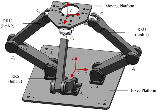
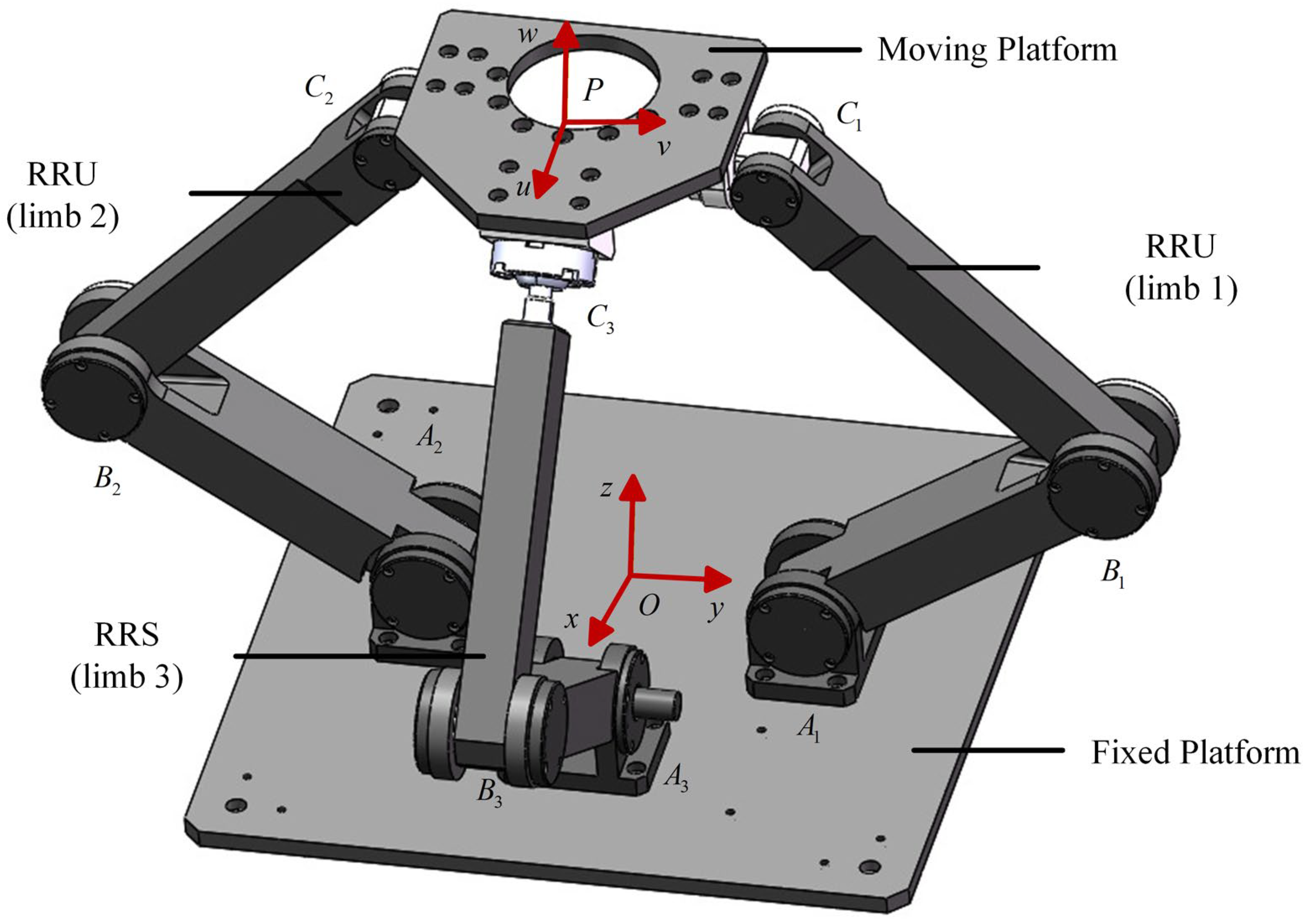
This paper focuses on the 2RRU-RRS parallel robot. This parallel robot consists of a fixed platform, a moving platform, two RRU limbs, and one RRS limb. The detailed structure is shown in Figure 1. The two RRU limbs are arranged symmetrically in the same plane, and the RRS limb is arranged in a plane perpendicular to the plane where the two RRU limbs are located. In the initial state, the fixed platform and the moving platform are in a horizontal position. The 2RRU-RRS parallel robot adjusts the end position of the moving platform by actuating the three R-joints connected to the fixed platform. The mechanism has rotational degrees of freedom about the and axes, and a translational degree of freedom along the axis. To mathematically describe the motion, a fixed coordinate system is established at the center of the base, and a moving coordinate system is attached to the platform.
Figure 1.
Three-dimensional model of the 2RRU-RRS parallel robot.
2.2. Inverse Kinematics Modeling
The theoretical kinematic boundary of the 2RRU-RRS parallel robot is established by analyzing the geometric constraints of its closed-loop limbs. For the i-th limb, a closed-loop vector equation can be established from the origin of the fixed platform, passing through the rods of the limb, and reaching the moving platform, which can be expressed as:
where , and represent the position vectors of the base hinge, the actuated rod, and the passive rod, respectively. denotes the platform’s position, and is the vector from the moving platform center to the joint.
The detailed solution process can be found in Ref. [36]. After computation, the analytical solutions of the actuated joint angles are obtained as follows:
where , and represent the projection components of the vectors from the base hinge point to the moving platform hinge point along the , and axes, respectively.
As indicated by the above equations, strong nonlinear kinematic coupling exists between the moving platform and the limbs of the 2RRU-RRS parallel robot. Under ideal conditions, the closed-loop geometric constraints ensure deterministic motion of the mechanism, and the analytical solution of the driving joint angles in Equation (2) defines the nominal trajectory of the system.
However, in practical operation, joint wear and manufacturing tolerances inevitably introduce clearance into the kinematic pairs. The presence of clearance violates the ideal equality constraint in Equation (1), which could be relaxed into the following inequality to account for the admissible deviation induced by the clearance:
where denotes the clearance magnitude of the i-th joint. When , the joint angle is no longer uniquely determined but spans a feasible range around its nominal solution, with extent of variation governed by .
More importantly, this deviation evolves dynamically during motion. The clearance defines a bounded domain within which relative motion can occur, leading to intermittent loss and re-establishment of contact at the joint interface. Consequently, the originally continuous kinematic behavior transitions into a discontinuous process characterized by alternating constrained and unconstrained states, which constitute the fundamental source of impact interactions and subsequent nonlinear vibration responses.
2.3. Physical Mechanism Analysis of Faults
While Section 2.2 defines the mathematical violation of kinematic constraints, this section further elucidates how these violations manifest as measurable vibration signals through a physically interpretable mechanism chain.
In the presence of joint clearance, the ideal closed-loop constraint is no longer strictly enforced. Instead, a bounded and time-varying deviation is introduced into the kinematic relationship, the magnitude of which is directly governed by the clearance size. As the clearance increases, the deviation from the nominal trajectory becomes more pronounced, leading to intermittent loss of constraint enforcement during motion.
At the contact interface between the pin and bearing, this deviation gives rise to a nonlinear dynamic process characterized by alternating phases of free flight, impact contact, and sustained contact. During the free-flight phase, the pin temporarily loses contact within the clearance space, allowing relative motion to accumulate. A larger clearance tends to a longer free-flight distance, which enables the pin to reach a higher relative velocity before impact. Consequently, the impact intensity increases with the clearance magnitude, generating stronger short-duration impulsive forces.
These impulsive forces propagate through the rigid and symmetric multi-branch structure of the parallel robot and act as broadband excitations to the mechanical system. As a result, multiple structural vibration modes are simultaneously activated. The coupling among different kinematic chains further leads to multi-path transmission of these impact-induced responses, which increases the complexity of the overall vibration behavior.
Compared with bearing and gear faults, which typically generate periodic impacts associated with rotational speed or geometric frequencies and thus produce identifiable discrete spectral peaks, joint clearance faults in the 2RRU-RRS parallel robot are dominated by non-periodic impulsive excitations. The timing and intensity of these impacts are governed by the instantaneous kinematic state, clearance magnitude, and contact conditions, all of which vary continuously during operation. Therefore, the signals often exhibit intermittent or quasi-periodic impulsive responses with nonstationary amplitude and phase, making it difficult to identify stable characteristic frequencies based solely on rotational speed.
These characteristics provide a clear physical justification for adopting CWT-based time-frequency analysis in the proposed method, as it enables the capture of both transient impulsive features and their multi-scale energy distribution, which cannot be effectively revealed by conventional FFT-based approaches.
3. Methodology of the MS-ECA-ResNet
3.1. Method Overview
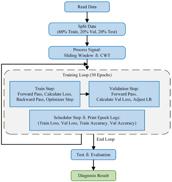
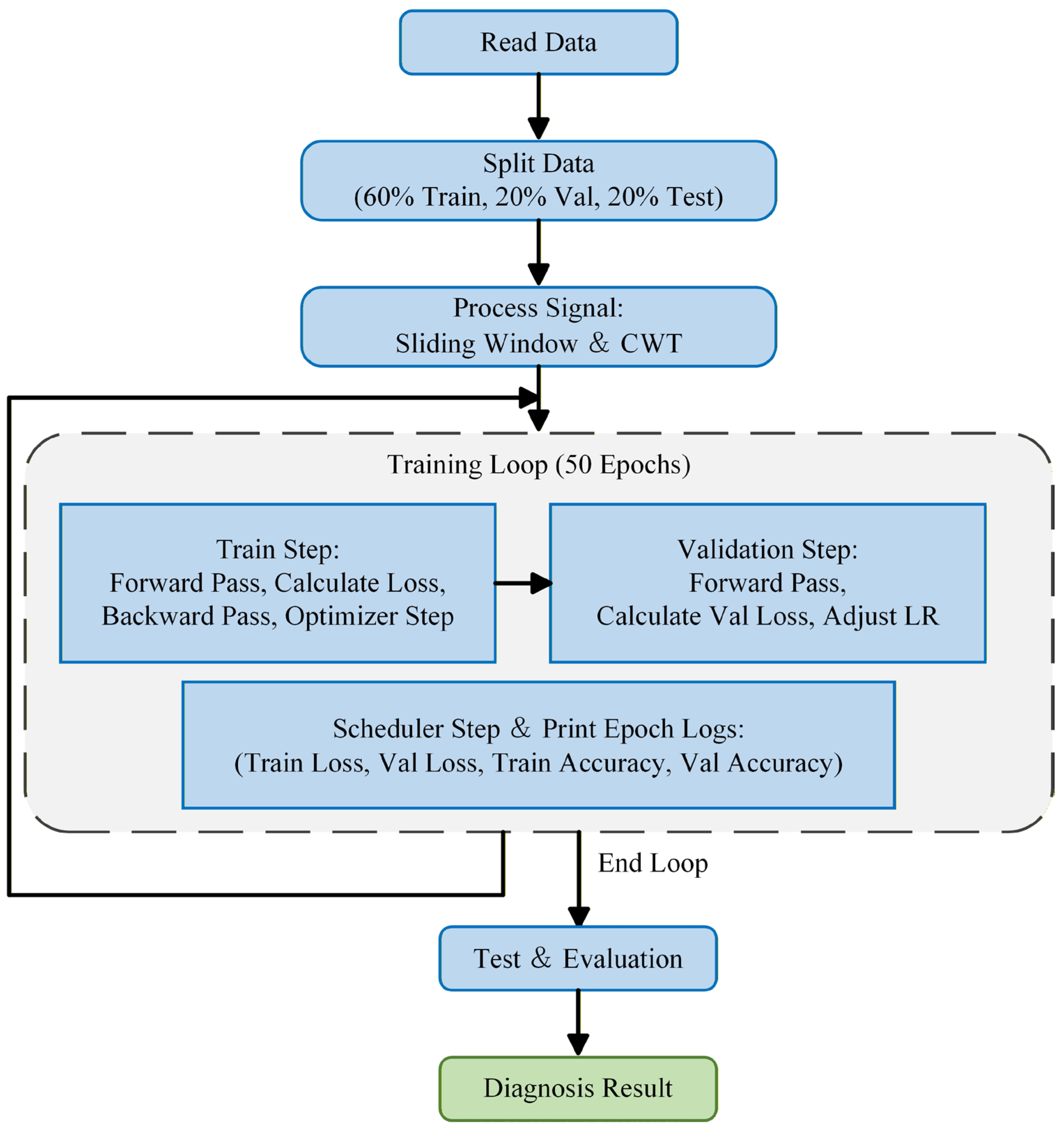
To address the non-stationary and strongly coupled characteristics exhibited by fault signals of the 2RRU-RRS parallel robot, this paper proposes a method named MS-ECA-ResNet. The overall workflow of the proposed method is illustrated in Figure 2. Firstly, vibration signals collected under different health states are partitioned into a training set, a validation set, and a testing set. These signals are then processed using the CWT to convert the one-dimensional time-series data into two-dimensional time-frequency images. Next, the time-frequency images serve as inputs to train the model for 50 epochs. Finally, the testing set is used to evaluate the performance of the model and output the final fault diagnosis results.
Figure 2.
Workflow of the MS-ECA-ResNet model.
3.2. Time-Frequency Imaging
The time-frequency image is a graphical representation of a signal that contains both time and frequency information. The horizontal axis of the time-frequency image shows the variation in the signal in the time domain, and the vertical axis shows the distribution of the signal in the frequency domain. The color intensity corresponds to the signal amplitude at specific time-frequency coordinates. Time-frequency imaging can be obtained in various ways, including Short-Time Fourier Transform (STFT), Continuous Wavelet Transform (CWT), and Gramian Angular Field (GAF). Among them, CWT is widely used for feature extraction in fault diagnosis tasks due to its multi-resolution analysis ability.
Given the non-stationary and transient impact characteristics of the fault signals in the 2RRU-RRS parallel robot, the CWT is employed as the signal time-frequency analysis tool. It simultaneously generates representations of the raw signal in the time and frequency domains [37], providing high-quality input data for the subsequent CNN.
The wavelet transform is defined as the inner product between the signal and a family of wavelet functions. This wavelet family is generated by translating and scaling a mother wavelet and can be expressed as:
where is the scale parameter inversely proportional to frequency, is the translation parameter, and the normalization factor is introduced to ensure energy normalization of the wavelet at different scales.
The CWT of the signal is obtained through convolution with the complex conjugate of the wavelet function and is defined as:
where denotes the complex conjugate of the mother wavelet function . By varying the scale parameter and the translation parameter , the original one-dimensional vibration signal can be mapped onto a two-dimensional time-frequency plane. This representation provides an intuitive description of the energy distribution of local signal features in the time-frequency domain.
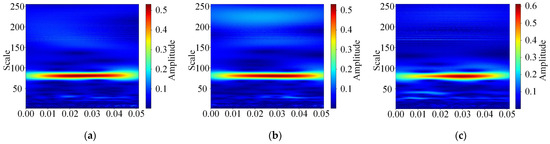
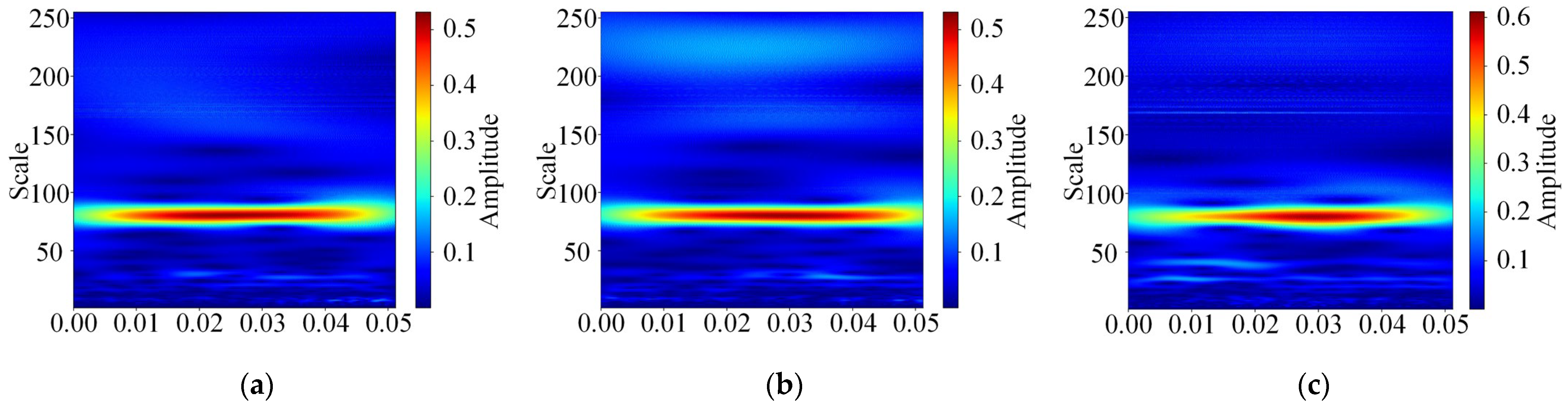
In this study, the complex Morlet wavelet was selected as the mother wavelet due to its morphological similarity to mechanical impact signals. Its center frequency and bandwidth parameters were set to 1.0 and 10.0, respectively. To balance computational efficiency with diagnostic performance, the CWT was computed over 255 scales ranging from 1 to 255. The pseudo-frequency at each scale was determined according to , where is the center frequency of the mother wavelet, and is the sampling interval, yielding a pseudo-frequency range of approximately 78.4 Hz to 20,000 Hz. This range was selected to cover the high-frequency structural resonance bands predominantly excited by the impulsive contact forces arising from joint clearance in this platform. To satisfy the input requirements of the multi-scale convolutional layer, min-max normalization was applied to the CWT amplitude matrix to map the coefficient magnitudes to the range [0, 255], and the resulting matrix was subsequently mapped to the JET color map. Finally, the images were resized to 224 × 224. The image after CWT is shown in Figure 3. In this figure, the red regions signify high-energy components, whereas the blue regions represent low-energy levels.
Figure 3.
Time-frequency image obtained by CWT. (a) training set; (b) validation set; (c) testing set.
3.3. Architecture of MS-ECA-ResNet
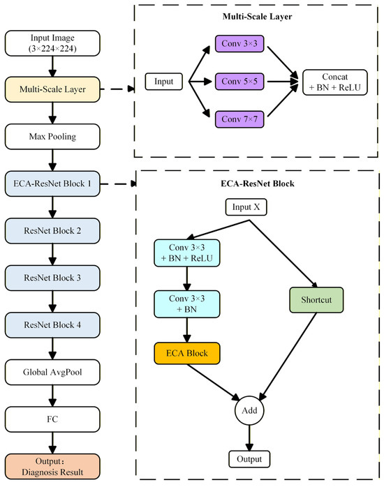
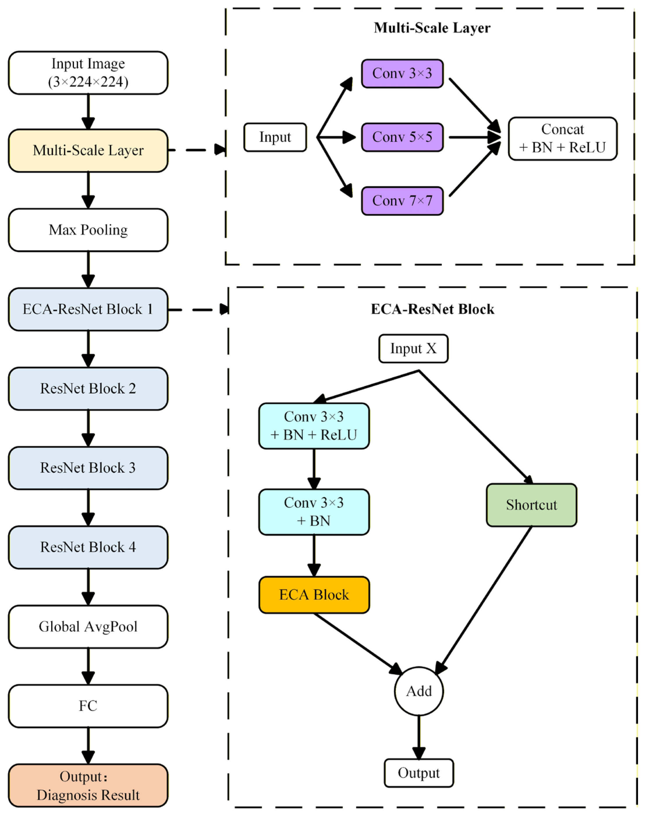
The detailed architecture of the proposed MS-ECA-ResNet is illustrated in Figure 4. The network first employs multi-branch convolutional layers to extract rich multi-scale time-frequency features. Subsequently, an improved residual module is introduced by embedding the ECA block. This design enhances the weights of key fault feature channels while suppressing noise interference, without significantly increasing the number of parameters. Finally, label smoothing is applied to the cross-entropy loss, improving the generalization capability of the model.
Figure 4.
Structure of the MS-ECA-ResNet.
3.3.1. Multi-Scale Feature Extraction Layer
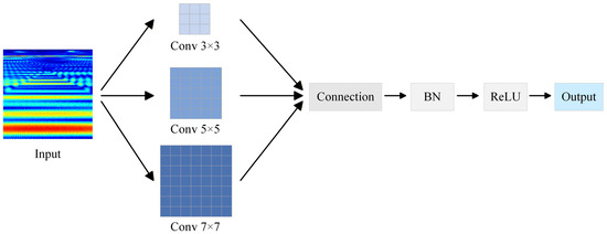
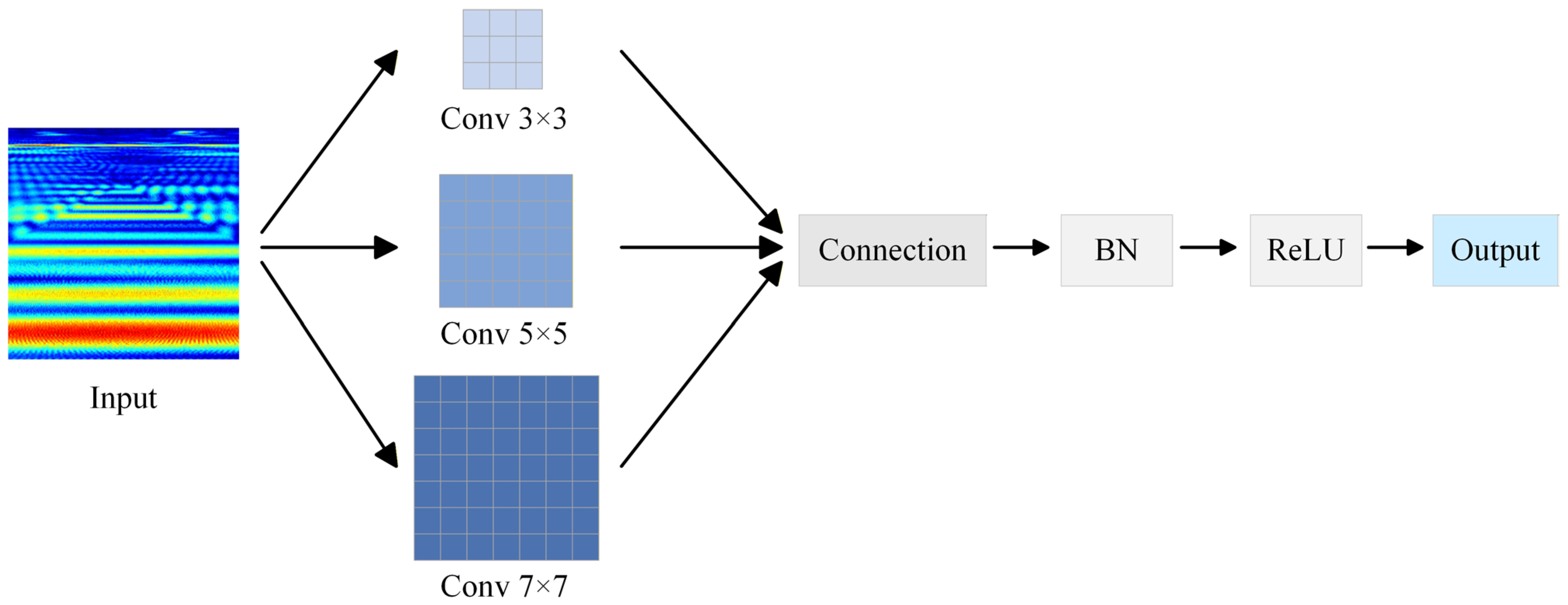
Traditional CNNs usually use a single-sized convolution kernel in the first layer. However, for the 2RRU-RRS parallel robot, the multi-chain coupled structure introduces a fundamental challenge for single-scale feature extraction. Due to the strong kinematic coupling among the three branches, fault-induced vibrations propagate simultaneously through multiple kinematic limbs, generating fault signatures that span different time scales and frequency bands. A single fixed-size kernel is therefore inherently limited in its ability to simultaneously capture features at different levels of the structural hierarchy. To address this, a parallel multi-scale convolution layer is designed as the first layer of the network, specifically tailored to the mechanical topology of the robot. As illustrated in Figure 5, the input time-frequency image is simultaneously processed by three convolutional branches. The 3 × 3 branch is designated to extract joint-level transient features; the 5 × 5 branch captures limb-level vibration patterns; and the 7 × 7 branch extracts system-level global resonance characteristics [38].
Figure 5.
Workflow of the Multi-scale feature extraction layer.
The convolution kernels of the three branches perform convolution on the input three-channel time-frequency image along the spatial dimensions and compute the corresponding dot products. The calculation process can be expressed as:
where represents the weight of the i-th branch, represents the input image of the convolutional layer, and represents the bias term. The feature maps extracted by the three parallel branches are concatenated in the channel dimension. The concatenated features are then passed through a Batch Normalization (BN) layer and a ReLU activation function, yielding an initial feature map fused with multi-scale information.
3.3.2. Efficient Channel Attention Block
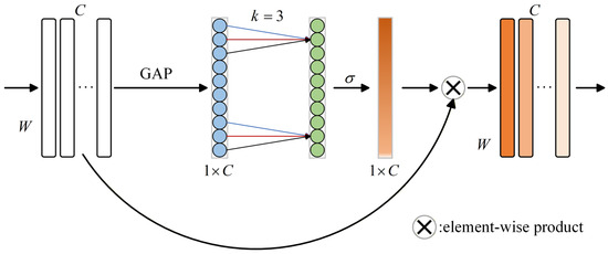
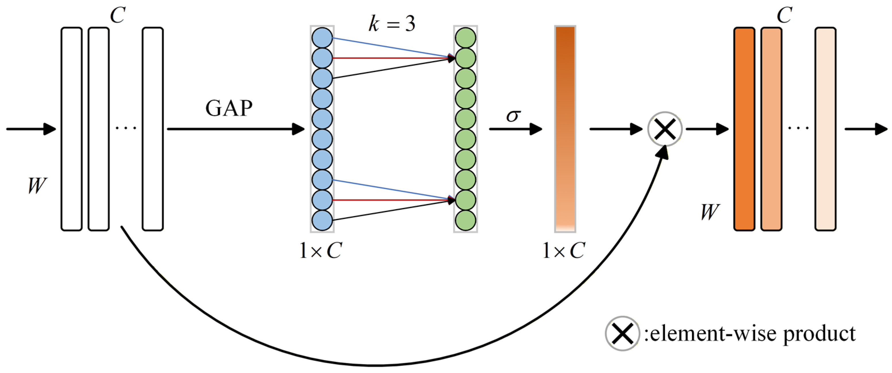
Although each filter in the neural network can adaptively extract input features, traditional convolution operations typically treat all channels equally. In the specific context of the 2RRU-RRS parallel robot, the three-limb symmetric layout leads to significant signal redundancy under normal conditions. To address this, this method introduces the ECA block into the residual network. This design is intended to automatically recalibrate channel weights, thereby prioritizing fault-sensitive features generated by specific motion disturbances. Concurrently, it suppresses redundant and symmetrical background interference, which ultimately enhances the model’s overall interference suppression capability. The architectural framework of the ECA block is illustrated in Figure 6.
Figure 6.
The framework of the ECA block.
Compared with the classic SE channel attention mechanism, the ECA mechanism adopts a local cross-channel interaction strategy without dimensionality reduction. This design avoids information loss caused by dimensionality reduction and preserves channel integrity. In addition, the number of parameters of the ECA mechanism is much less than that of the SE attention mechanism, which greatly improves the inference speed of the model. Assume denotes the feature map output by the residual network, where is the number of channels and represents the spatial dimensions. Firstly, global average pooling (GAP) is performed to obtain the aggregated feature of each channel. Then, the convolution kernel is used to calculate the weight value of each channel. Finally, the generated channel weights are multiplied by the feature map channel-by-channel to obtain the recalibrated feature map . The calculation process of the ECA mechanism can be expressed as follows:
The ECA block is embedded after the convolution layer of the residual block and before the residual addition. This design enables the network to adaptively enhance feature channels containing fault impact components while suppressing channels dominated by environmental noise before feature fusion. Consequently, this improves the model’s fault diagnosis accuracy and robustness under complex working conditions.
3.3.3. ECA-ResNet Block
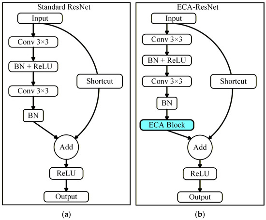
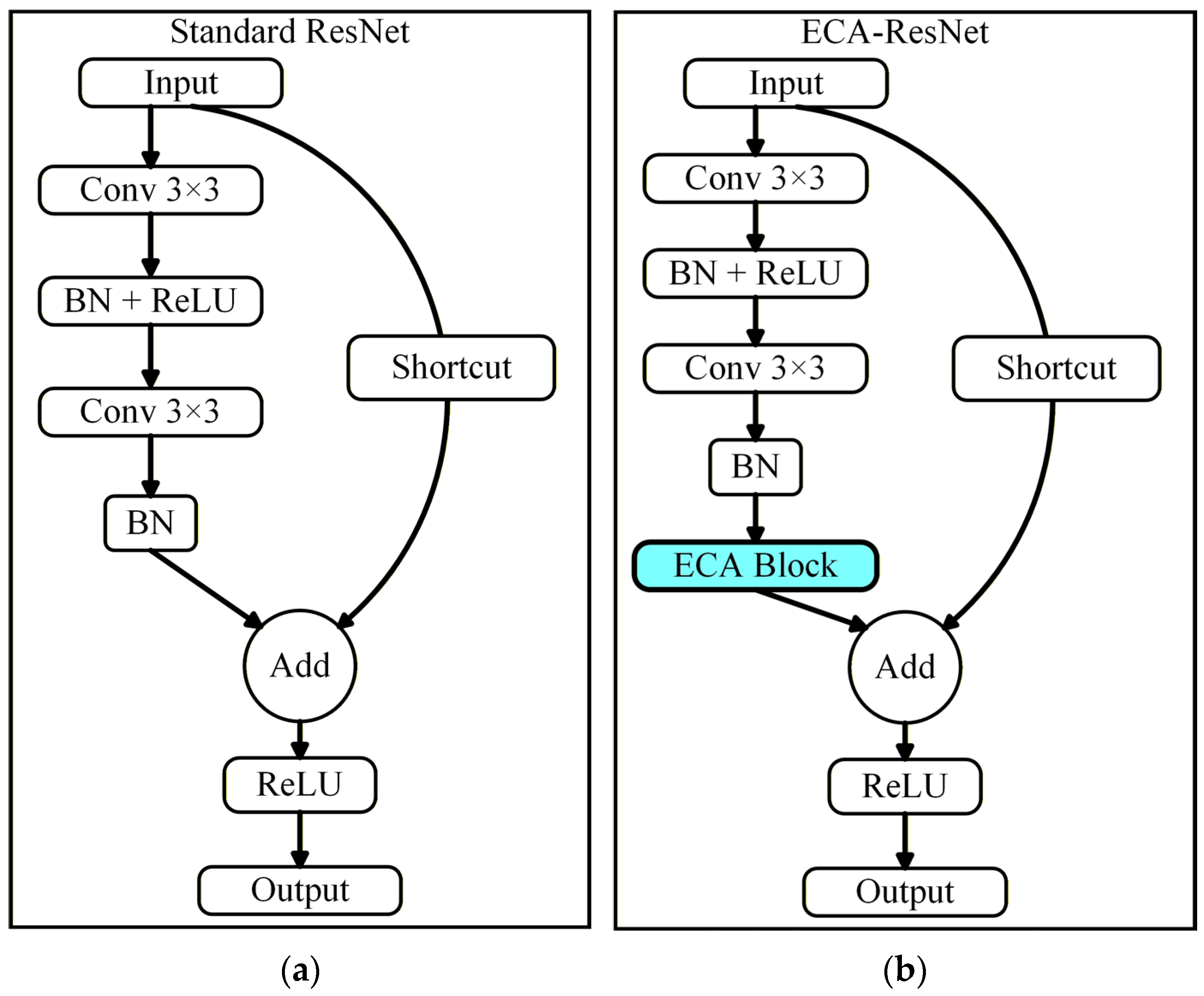
In deep learning-based fault diagnosis tasks, extracting nonlinear features from vibration signals often requires neural networks with deep architectures. However, as network depth increases, traditional CNNs often suffer from the degradation problems. Specifically, increasing the number of layers may lead to higher training errors and cause the vanishing or exploding gradient problem. To address this training bottleneck in deep networks, He et al. [39] introduced the ResNet deep network framework based on residual learning. Residual learning enables efficient feature transmission while maintaining network depth. Building upon this, this study introduces a residual learning structure into the backbone network and further embeds the ECA mechanism, thereby constructing an attention-enhanced residual network module. The structural composition of the standard ResNet block and its ECA-integrated variant is illustrated in Figure 7.
Figure 7.
(a) Standard ResNet structure; (b) ECA-ResNet structure.
As shown in Figure 7a, the standard ResNet block typically consists of two or three cascaded convolutional layers, whose output is added to the input via a shortcut connection. Unlike traditional networks that aim to directly learn the underlying mapping from input to output, ResNet shifts the learning objective to fitting a residual function , defined as . For the i-th residual building block, the learned residual feature is summed with the input to yield the output of the current layer . The calculation process can be expressed as follows:
where typically employs the ReLU activation function, and represents the residual path encompassing operations such as convolution and BN.
To further enhance the model’s capability to extract fault features from parallel robots, an ECA-ResNet block is constructed based on the standard ResNet block. Its specific structure is shown in Figure 7b. The modified block retains the standard dual-layer 3 × 3 convolution path structure. The ECA block is embedded immediately after the second BN layer in the main path, before the element-wise addition with the shortcut connection. The network backbone is formed by stacking four such ECA-ResNet blocks. As the network deepens, the number of feature channels progressively increases. During down-sampling operations, the spatial resolution of the feature maps is reduced, encoding spatial information into higher-dimensional channel representations. Subsequently, ReLU activation is applied to introduce nonlinearity. Finally, the features are passed through a global average pooling (GAP) layer, a Dropout layer, and a fully connected (FC) layer to output the final fault classification predictions.
3.4. Fault Diagnosis Using an MS-ECA-ResNet
3.4.1. Overall Framework of the Fault Diagnosis Method
The overall workflow of the parallel robot fault diagnosis method, based on the proposed MS-ECA-ResNet, is shown in Figure 2. The general procedure is outlined as follows:
- Data Acquisition and Preprocessing: Vibration accelerometers collect the signals of the parallel robot under different health states. Firstly, the collected vibration signals are divided into three mutually independent and non-overlapping segments in the time dimension, which are used for training, validation and testing, respectively. Subsequently, the sliding window technique is applied within each independent segment to generate samples. This process ensures that the training samples, validation samples and test samples do not come from the same or adjacent time periods, thereby eliminating the potential risk of data leakage.
- Model Construction: A fault diagnosis model for the parallel robot is constructed based on the MS-ECA-ResNet. The network is trained iteratively using the training and validation sets, yielding the optimized fault diagnosis model.
- Prediction and Evaluation: The unseen test set is fed into the trained network to predict the health status of the parallel robot and evaluate the final diagnostic performance.
3.4.2. Network Configuration
The MS-ECA-ResNet designed in this paper generally consists of one multi-scale feature extraction layer and four ECA-ResNet residual modules. The inputs to the model are 224 × 224 color time-frequency images generated by CWT. Its detailed network structure parameters and output dimensions are presented in Table 1. During the training process, the network down-samples the feature map through the max pooling layer to reduce spatial resolution and expand the receptive field, thereby reducing computational complexity. As the network depth increases, the residual structure effectively alleviates performance degradation during training. Meanwhile, the ECA mechanism adaptively adjusts channel-wise feature responses, enhancing fault-related feature channels.
Table 1.
Detailed configuration of the MS-ECA-ResNet.
3.4.3. Model Training Algorithm
To obtain the optimal model parameters that exhibit superior generalization capabilities, a comprehensive model training and optimization strategy is devised in this study.
During the training phase, the time-frequency images are fed into the constructed MS-ECA-ResNet. Time-frequency features are progressively extracted through forward propagation, and the corresponding fault category predictions are produced at the output layer of the network. A cross-entropy loss function with label smoothing is employed to measure the discrepancy between the predictions and the ground truth labels, thereby alleviating model overconfidence and improving the robustness of classification decisions. For parameter optimization, the AdamW optimizer is adopted to update the network weights, coupled with a cosine annealing learning rate schedule.
The model parameters are updated via the backpropagation algorithm during each training iteration, while the model’s performance is evaluated on a validation set at the end of each epoch. Upon convergence, a stable fault diagnosis model is obtained. The complete training procedure for the MS-ECA-ResNet is summarized in Algorithm 1.
| Algorithm 1: MS-ECA-ResNet Fault Diagnosis Framework |
| Input: Raw vibration signal dataset , number of fault classes , number of training epochs , batch size . Output: Trained diagnostic model M, fault classification results. |
|
4. Experiment and Analysis
In this section, to verify the fault diagnosis performance of the MS-ECA-ResNet, we conducted experiments on the vibration signals collected from the 2RRU-RRS parallel robot experimental platform. Comparisons with traditional machine learning methods and representative deep learning models demonstrate the effectiveness of the proposed method for parallel robot fault diagnosis. Furthermore, noise robustness evaluations and ablation studies are carried out to further validate the reliability and superiority of the proposed method.
4.1. Data Acquisition and Preprocessing
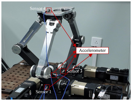
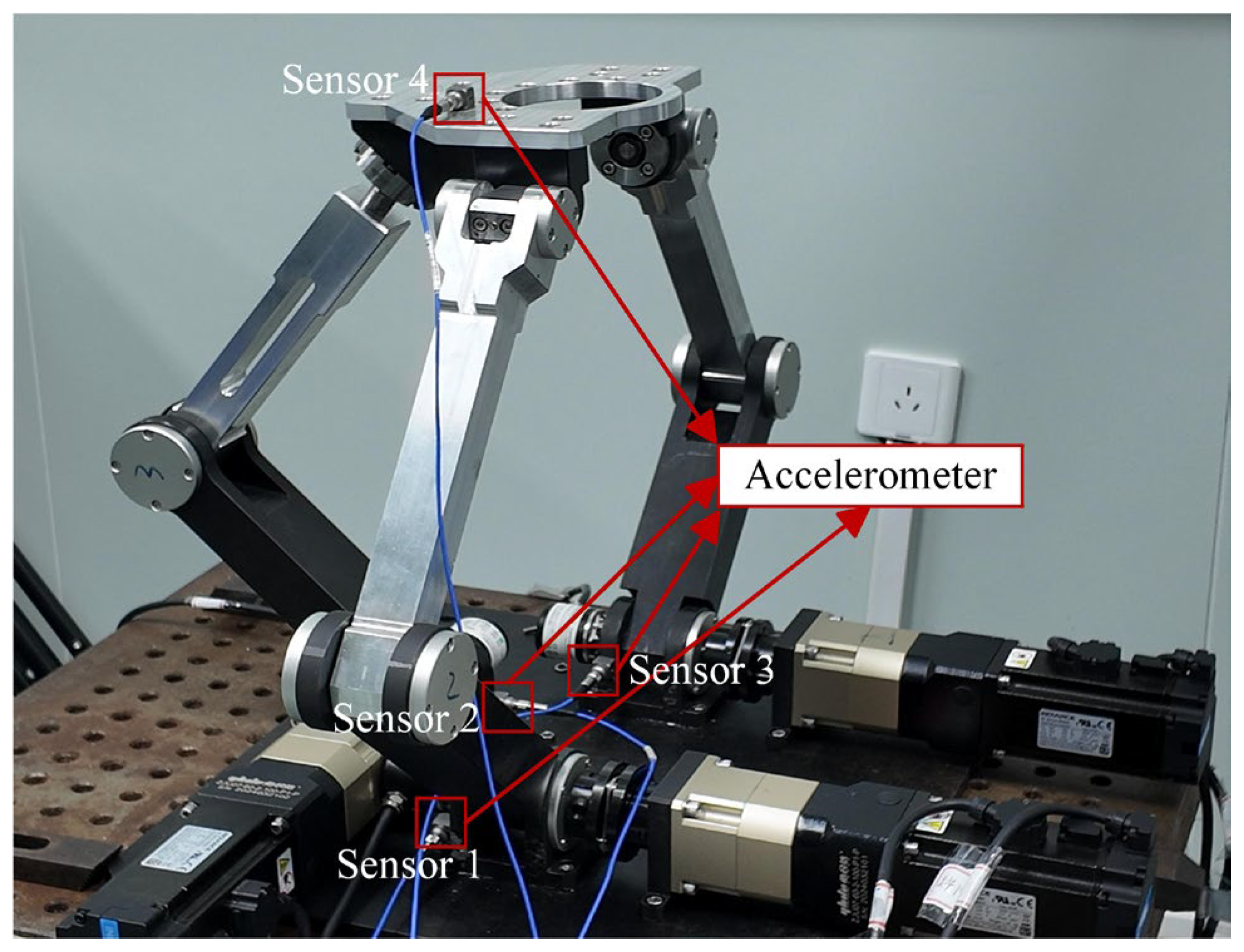
As shown in Figure 8, a 2RRU-RRS parallel robot experimental platform was constructed to collect vibration signals to verify the effectiveness of the proposed MS-ECA-ResNet. All vibration signal data used in this study were acquired from this experimental platform. The platform was specifically designed to simulate clearance faults in the actuated joints of the parallel robot and to measure vibration signals under various fault conditions. To monitor the mechanical integrity of the system, four accelerometers (Model 1A339E) were deployed at strategically selected locations. As shown in Figure 8, three accelerometers (Sensors 1, 2, and 3) were firmly installed in the outer bearing seats of the three actuated joints on the fixed platform, positioned as close as possible to the clearance joints to maximize the sensitivity to impact-induced vibrations. The fourth accelerometer (Sensor 4) was mounted on the top surface of the moving platform to capture the integrated dynamic response of the end-effector. The specific mounting positions of all four sensors are indicated by the red arrows in Figure 8. The sampling frequency is 20 kHz.
Figure 8.
Experimental platform.
Regarding sample generation, a weighted fusion strategy was applied to the signals from the three actuated joint accelerometers (Sensors 1, 2, and 3). Specifically, the fused signal is computed as a weighted sum of the three joint signals, with equal weights of 1/3 assigned to each channel. This equal-weight scheme was adopted because the three actuated joints are structurally symmetric in the 2RRU-RRS mechanism, and no prior information was available to justify differential weighting. This strategy incorporates multi-source information from all three joints while minimizing redundancy. The signal from the fourth accelerometer mounted on the moving platform was used as a supplementary monitoring channel to capture the overall dynamic response of the end-effector, but was not included in the fusion process for sample generation, as it primarily reflects the integrated response of the entire mechanism rather than localized joint-level fault features.
In our experiment, seven health conditions were simulated under a uniform fixed motion trajectory to reflect the different stages of dynamic deterioration, including a normal state and six faulty states. These states can be further classified into single clearance states and coupled clearance states. The specific details are shown in Table 2. The clearance magnitudes of 0.3 mm, 0.7 mm, and 1.0 mm were selected to represent progressively increasing levels of joint degradation. As demonstrated in [40], increasing clearance in parallel mechanisms leads to growing displacement deviations and increasingly pronounced nonlinear vibration responses.
Table 2.
Health states of the 2RRU-RRS parallel robot.
In the dataset, vibration signals collected under the same health condition were regarded as one class. For each health state, 471 training samples, 157 validation samples and 157 test samples were extracted from the independent original signal segments as defined above. This approach avoids the risk of data leakage and enables a rigorous assessment to be conducted. The number of samples is sufficient to represent the non-stationary and transient impact characteristics, which is guaranteed by the high overlap rate of the sliding window. Specifically, the window length is 1024 points, the step size is 256 points, and the overlap rate is maintained at 75%. This strategy serves as a form of temporal data augmentation, ensuring that transient impact events are captured multiple times at different time offsets, thereby enabling the model to learn robust discriminative features from the impact characteristics.
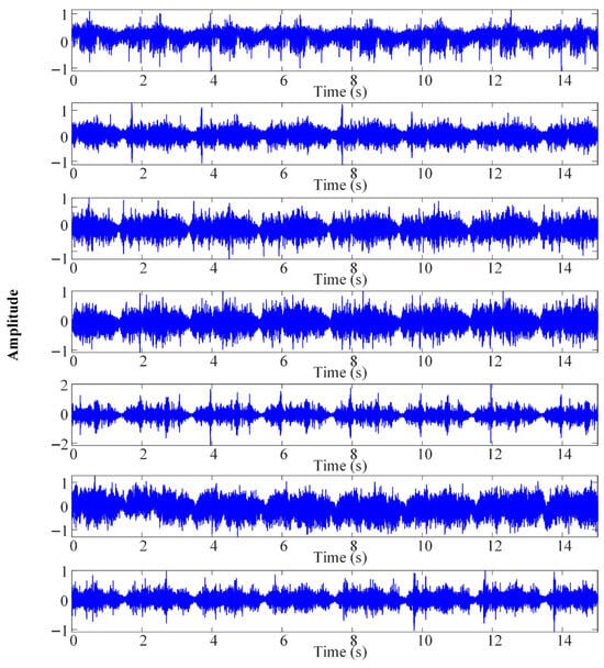
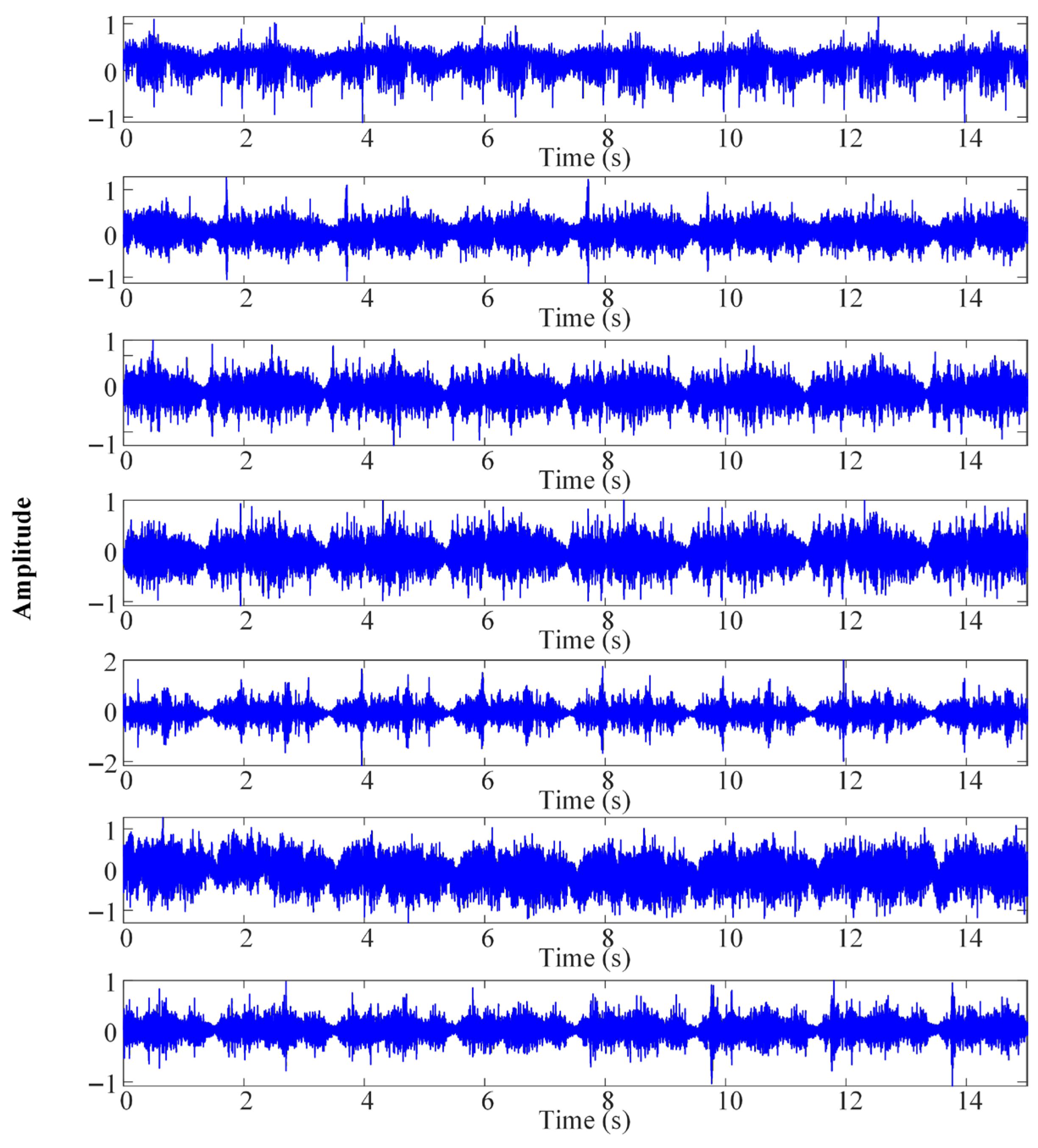
Each sample contains 1024 sampling points, corresponding to a time duration of approximately 51.2 milliseconds. This time duration is designed to prioritize capturing high-frequency pulsed transient signals rather than long-period low-frequency modulated signals. In a high-stiffness parallel mechanical structure, the fault-sensitive information mainly concentrates in the high-frequency structural resonances triggered by joint collisions. The 51.2-millisecond window provides sufficient time resolution to cover multiple collision events, while ensuring that the MS-ECA-ResNet can efficiently extract distinctive features from the time-frequency images. The time-domain waveforms shown in Figure 9 are derived from the fused signals of the three actuated joint accelerometers under seven health conditions.
Figure 9.
Time-domain waveforms of the 2RRU-RRS parallel robot under seven health states (derived from the fused signals of Sensors 1, 2, and 3 with equal weights of 1/3).
4.2. Comparative Analysis
4.2.1. Comparative Study of Different Diagnostic Methods
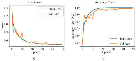
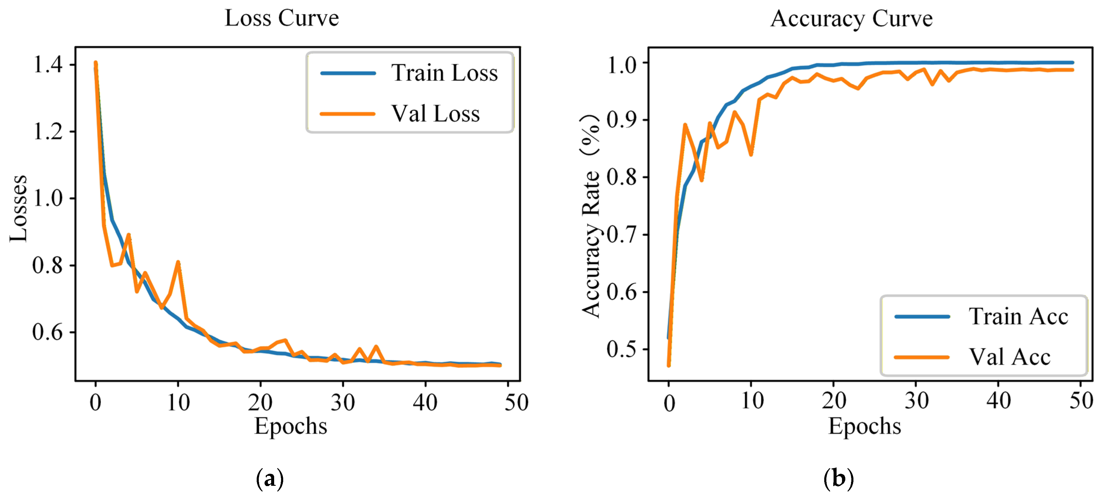
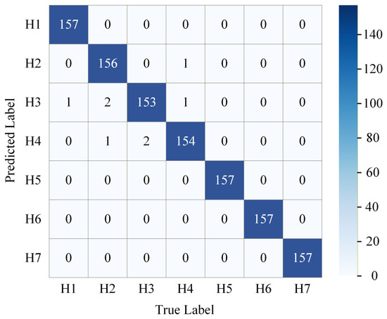
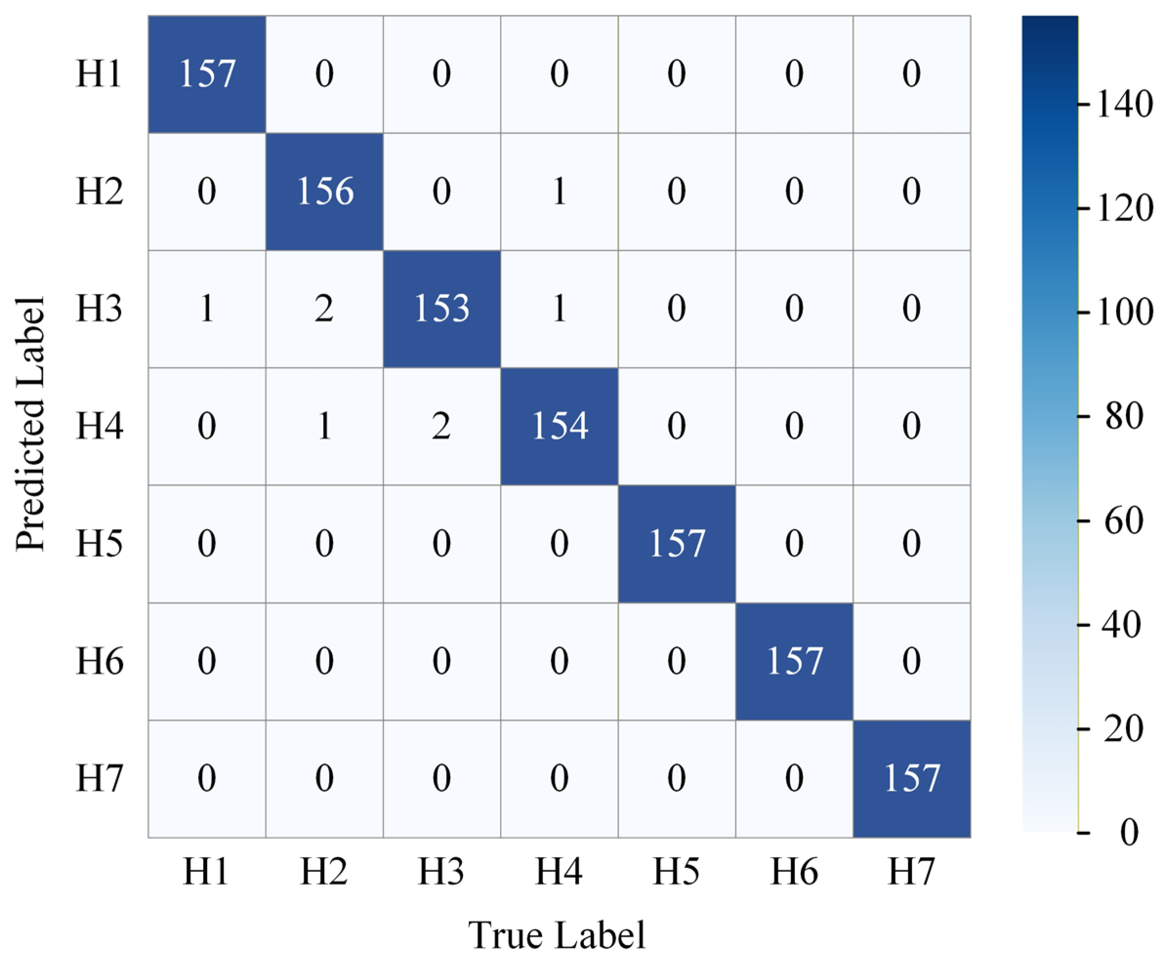
The fault diagnosis performance of the proposed MS-ECA-ResNet was evaluated using the vibration signals collected under the seven health conditions of the 2RRU-RRS parallel robot. The convergence curves of the proposed network are shown in Figure 10, and the confusion matrix obtained on the test set is presented in Figure 11. To comprehensively evaluate the diagnostic performance of the proposed method, representative methods from different categories were selected for comparison. Specifically, three traditional machine learning methods (BP, SVM, and RF) were included as classic data-based diagnostic models, while two widely used deep convolutional neural networks (VGG16 and ResNet18) were adopted as modern deep learning comparison models.
Figure 10.
(a) Loss curves of the MS-ECA-ResNet; (b) accuracy curves of the MS-ECA-ResNet.
Figure 11.
Confusion matrix of the MS-ECA-ResNet.
To ensure the fairness and rigor of the benchmarking process, the deep learning models VGG16 and ResNet18 utilized the same 224 × 224 RGB images as the proposed method. For traditional machine learning models (BP, SVM, and RF), the CWT images were flattened into high-dimensional feature vectors so that all models can be trained using the same time-frequency information source.
Furthermore, the same data partitioning and preprocessing steps were adopted for all methods. The training set, validation set and test set for all models were exactly the same. All experiments were independently repeated 5 times, and the average results were reported. The hyperparameters of the comparison models were selected based on common settings and adjusted within a reasonable range. The number of training rounds was consistent with the proposed method to ensure the fairness of the comparison. The diagnosis results are shown in Table 3.
Table 3.
Diagnostic results of different models.
Figure 10a,b shows the loss function curves and accuracy curves of the MS-ECA-ResNet on the training and validation sets. As shown in the figure, both the training and validation losses decrease rapidly during the initial training phase and gradually converge to stable minimums in the later epochs. The trend of training loss and validation loss is highly consistent. Similarly, the training and validation accuracies increase rapidly in the early epochs, converge after about 20 epochs, and finally plateau at a high level. The minimal gap between the training and validation accuracies indicates the absence of significant overfitting. These loss and accuracy curves verify the training stability and model effectiveness of the proposed method in the fault diagnosis task using raw vibration signals. Figure 11 presents the confusion matrix of the proposed MS-ECA-ResNet on the test set. Each fault category comprises 157 test samples. The confusion matrix demonstrates that almost all fault samples are accurately classified, confirming the effectiveness of the proposed method for parallel robot fault diagnosis.
As shown in Table 3, the proposed method outperforms the comparative models in terms of maximum, minimum, and average classification accuracy. The proposed method achieves a diagnostic accuracy of 98.95% with a standard deviation of 0.18%. In contrast, the BP neural network and RF model yield average accuracies of 93.19% and 88.26%, respectively, with relatively large standard deviations, indicating inferior stability across multiple independent trials. The SVM model yields identical diagnostic results across 5 experiments, with an average accuracy of 84.62%; however, its overall diagnostic performance remains significantly lower than that of the deep learning models. Both VGG16 and ResNet18 demonstrate relatively high diagnostic accuracy in this task. In particular, ResNet18 achieves an average accuracy of 97.10%; however, the performance of both models is still lower than that of the proposed method.
4.2.2. Impact of Window Step Size on Diagnostic Performance
While the previous results confirm the model’s superiority, it is crucial to investigate the impact of window overlap on diagnostic integrity. To address the potential issues of data leakage and to evaluate the diagnostic performance of the model under more stringent conditions, we conducted an experiment regarding the window step size. The step size of the sliding window was increased from 256 to 512 and 1024, respectively. The experimental results are shown in Table 4.
Table 4.
Diagnostic performance of MS-ECA-ResNet across different window step sizes.
As illustrated in Table 4, the diagnostic accuracy of the MS-ECA-ResNet exhibits a gradual downward trend as the step size increases. Specifically, in the non-overlapping setting (step size = 1024), the average accuracy drops to 94.36%, with a maximum accuracy of 95.36%. This decline is primarily attributed to two factors: first, the total number of training samples is reduced by 75% compared to the standard setting (step size = 256); second, the removal of overlapping windows eliminates the potential auxiliary information provided by temporal correlation.
However, even in the most stringent non-overlapping scenarios, the accuracy of the proposed method (94.36%) is still higher than that of traditional machine learning methods (such as SVM at 84.62% and RF at 88.26%), and is comparable to that of typical deep learning architectures (such as VGG16 at 94.26%). Moreover, the gap between the maximum and minimum accuracy under all step sizes is small, indicating the training stability of the proposed MS-ECA-ResNet. These results demonstrate that this model can effectively extract intrinsic fault features from time-frequency images after wavelet transformation, rather than relying on temporal proximity.
4.3. Diagnostic Performance Under Noisy Environments
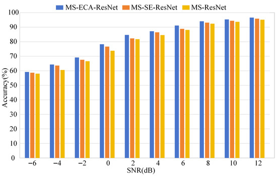
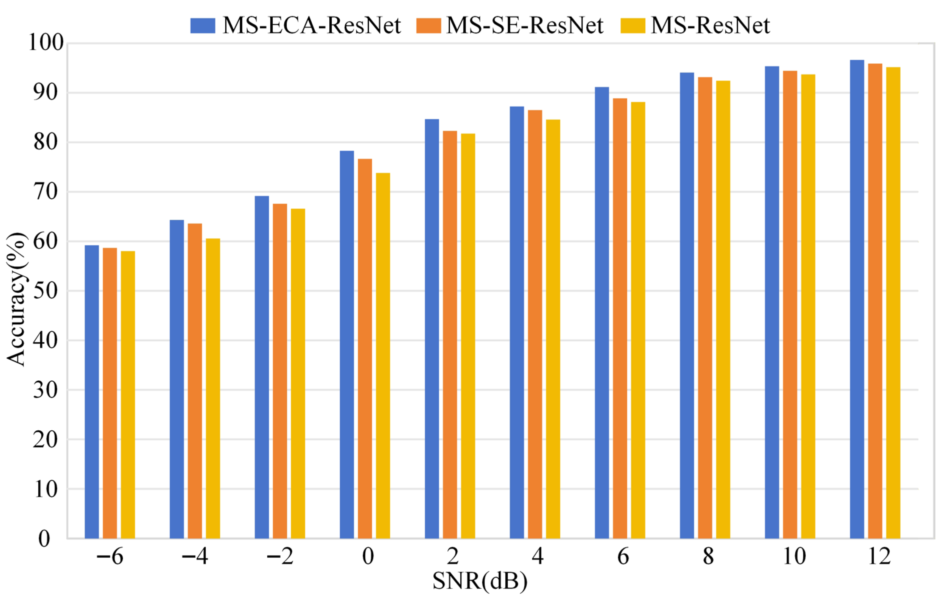
In practical industrial applications, parallel robots may operate in noisy environments. In such cases, the collected vibration signals are prone to being contaminated by background noise. In this section, we focus on evaluating the noise robustness and diagnostic performance of the MS-ECA-ResNet. To simulate industrial noise environments, Gaussian white noise with different signal-to-noise ratios (SNR) is added to the acquired raw vibration signals. The SNR values are set to range from −6 dB to 12 dB. A lower SNR indicates a stronger influence of noise on the raw signal; in particular, when the SNR is −6 dB, the noise energy is approximately four times that of the raw signal. In this study, a multi-scale residual network equipped with an SE mechanism (MS-SE-ResNet) and without any attention mechanism (MS-ResNet) are selected as comparison models for fault diagnosis. The diagnostic accuracies of different models under various noise conditions are presented in Table 5 and Figure 12.
Table 5.
The prediction accuracies of three models under different SNR values.
Figure 12.
Comparison of prediction accuracies with different SNR values.
As illustrated in Figure 12, the diagnostic accuracy of all three residual network models shows an upward trend as the SNR value increases. At low SNR levels, severe noise interference inevitably degrades the diagnostic accuracy of the models. However, under noisy operating conditions, residual networks incorporating attention mechanisms exhibit superior fault diagnosis performance compared with those without attention. This demonstrates that the channel attention mechanism can effectively improve the diagnostic accuracy of the model in complex environments to a certain extent. Furthermore, as shown in Table 5 and Figure 12, the MS-ECA-ResNet model consistently maintains the best performance throughout the SNR transformation process. This verifies the feasibility and effectiveness of the proposed method for applications in simulating industrial noise environments.
4.4. Ablation Study
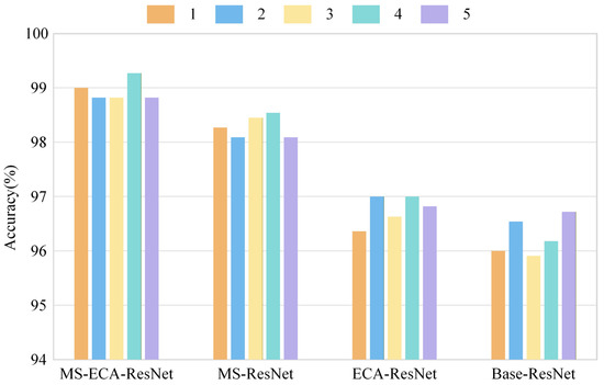
To further verify the effectiveness of the multi-scale feature extraction layer and the ECA mechanism, a systematic ablation study is conducted in this section. Specifically, three comparative models are constructed: a model incorporating only the multi-scale feature extraction layer (MS-ResNet), a model incorporating only the ECA mechanism (ECA-ResNet), and a baseline model without the above improvements (Base-ResNet). In the experiment, the four models were tested using the raw vibration signals, and the same dataset division and training strategy were adopted. The overall results of the ablation study are presented in Table 6, and the detailed performance comparisons are illustrated in Figure 13.
Table 6.
Diagnostic results of the ablation experiments.
Figure 13.
Detailed diagnostic results of the ablation study across five independent trials.
Table 6 and Figure 13 together present the diagnostic results of different models over multiple trials. The results show that the diagnostic metrics of the proposed MS-ECA-ResNet are superior to those of other comparison models, demonstrating the best diagnostic performance. Specifically, the average diagnostic accuracy of MS-ECA-ResNet reaches 98.95% with a standard deviation of 0.18%. According to the statistical analysis in Table 6, the 95% confidence interval of the proposed method is [98.70, 99.19], which does not overlap with that of the MS-ResNet model ([98.03, 98.54]), indicating the high stability and reliability of the proposed framework.
Compared with the baseline model Base-ResNet, the diagnostic accuracy has increased by approximately 2.68%. Further comparison among the ablation models shows a performance improvement when the multi-scale feature extraction structure is introduced, and a similar gain is observed when only the ECA mechanism is employed. The most significant improvement is achieved when both components are incorporated simultaneously.
To evaluate the significance of these improvements, a 95% confidence interval (95%CI) and p-value tests were used as evaluation metrics. As shown in Table 6, the p-values for all comparisons are less than 0.01, which statistically confirms that the performance gain is not due to random variation but reflects a significant enhancement in feature extraction capability. Although the absolute accuracy improvement is 0.66% compared with the model using only the multi-scale layer (MS-ResNet), this refinement leads to a 38.6% relative reduction in the classification error rate (from 1.71% to 1.05%). This advantage becomes more evident under complex operating conditions, validating that the integration of the ECA mechanism is essential for enhancing diagnostic robustness.
It should also be noted that the baseline ResNet architecture already exhibits strong feature extraction capability for time-frequency representations. Therefore, achieving further improvement on this basis is inherently challenging. The consistent performance gain obtained by the proposed MS-ECA-ResNet demonstrates that the integration of the multi-scale feature extraction module and the ECA mechanism effectively refines the learned feature representations and enhances the robustness of the diagnostic model under complex operating conditions.
4.5. T-SNE Visualization Analysis
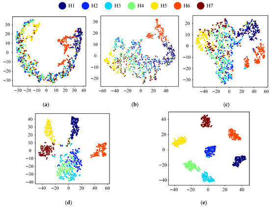
To intuitively analyze the features learned by the model, t-distributed stochastic neighbor embedding (t-SNE) is employed to project high-dimensional feature representations into a two-dimensional space. This visualization further facilitates the evaluation of the feature learning capability of the proposed MS-ECA-ResNet on the raw dataset. Figure 14 presents the visualization results obtained after the multi-scale feature extraction layer and the four ECA-ResNet blocks. By observing the changes in feature distributions, the discriminative capability of the model for different fault states during feature extraction can be clearly reflected.
Figure 14.
t-SNE visualization of data distributions: (a) t-SNE visualization of the multi-scale feature extraction layer; (b) t-SNE visualization of ECA-ResNet block 1; (c) t-SNE visualization of ECA-ResNet block 2; (d) t-SNE visualization of ECA-ResNet block 3; (e) t-SNE visualization of ECA-ResNet block 4.
Figure 14a–d illustrate the feature distributions during the intermediate learning stages of the MS-ECA-ResNet, while Figure 14e presents the final feature distribution. From the images, the results show that as the depth of the network increases, after passing through the ECA-ResNet block, the features learned by the model become increasingly distinguishable. In Figure 14e, the various fault categories form compact and distinct clustering structures within the feature space. These clusters exhibit well-defined inter-class boundaries with negligible overlap. These visualizations demonstrate that the MS-ECA-ResNet progressively transforms shallow, entangled features into deep, highly discriminative representations. This result further confirms the effectiveness of the proposed method for parallel robot fault diagnosis.
5. Conclusions and Future Work
Parallel robot vibration signals exhibit complex characteristics, including non-stationarity, strong coupling induced by the symmetric multi-chain structure, and severe noise interference. These characteristics pose significant challenges to accurate fault feature extraction and reliable health state identification. To address these challenges, a fault diagnosis method based on MS-ECA-ResNet was developed for a 2RRU-RRS parallel robot. By leveraging CWT to transform one-dimensional signals into comprehensive time-frequency representations, the proposed method enables robust end-to-end feature extraction and classification.
The results demonstrate that the MS-ECA-ResNet has significant advantages in terms of diagnostic accuracy, stability, and robustness. Moreover, under different SNR conditions, the proposed model maintained high diagnostic performance in complex noise environments. This indicates its potential feasibility for practical industrial applications. In addition, ablation studies were performed to further validate the necessity and effectiveness of the multi-scale feature extraction strategy and the ECA mechanism.
Regarding the potential deployment of the proposed framework in industrial scenarios, the following implementation procedure is envisioned. First, vibration accelerometers are installed at the key actuated joints of the target robot to collect raw vibration signals. Second, the collected signals are segmented using a sliding window and transformed into time-frequency images via CWT with the same parameter settings used in this study. Third, the pre-trained MS-ECA-ResNet model is applied to perform automatic fault identification. If sufficient labeled data from the target environment are available, fine-tuning the model on site-specific samples would further improve diagnostic performance under the new operating conditions. However, we acknowledge that transferring this laboratory-scale validation to industrial factory workshops still faces practical challenges, including variability in operating conditions, differences in sensor installation configurations, and the limited range of fault types currently covered. Therefore, this study should be regarded as a preliminary feasibility study that demonstrates the feasibility of the proposed approach, rather than a ready-to-deploy industrial solution.
Although the proposed method achieves satisfactory experimental results in the fault diagnosis task of parallel robots, there are still some directions that are worthy of further research and improvement:
- This study focuses on a limited set of fault types simulated under controlled laboratory conditions. Future work will expand the experimental scope to include more fault modes and more complex operating conditions, such as compound faults and variable-load scenarios, to further verify the generalization ability of the model.
- The current validation is conducted under controlled laboratory conditions. Future work will explore the application of domain adaptation techniques, such as transfer learning and domain adversarial training, to improve performance under varying and cross-domain conditions.
- In addition, considering that clearance-induced vibration responses are influenced by the instantaneous kinematic states of the robot, future work will investigate multi-modal data fusion strategies by integrating vibration signals with kinematic information (e.g., encoder-based position and velocity signals), in order to enhance the robustness and generalization capability of the diagnostic model under variable operating conditions.
Author Contributions
Conceptualization, S.H. and L.X.; methodology, S.H.; software, S.H.; validation, S.H. and Y.Z.; investigation, S.H.; resources, W.Y., Z.W. and L.X.; data curation, S.H.; writing—original draft preparation, S.H.; writing—review and editing, S.H., Y.Z., S.L., W.Y. and L.X.; visualization, S.H., Z.W. and W.Y.; supervision, L.X., Z.W. and W.Y.; project administration, L.X.; funding acquisition, L.X. and Z.W. All authors have read and agreed to the published version of the manuscript.
Funding
The authors would like to acknowledge the financial support of the National Natural Science Foundation of China under Grant Nos. 52575039 and 52205023, the Young Elite Scientists Sponsorship Program by CAST under Grant No. 2023QNRC001, the Zhejiang Provincial Natural Science Foundation of China under Grant Nos. LZ26E050005 and LQN26E050041, the Science Foundation of Zhejiang Sci-Tech University (ZSTU) under Grant No. 24242189-Y, the Fundamental Research Funds of Zhejiang Sci-Tech University under Grant No. 25242161-Y, and the General Scientific Research Project of Zhejiang Province Education Department under Grant No. Y202456192.
Data Availability Statement
The data of the 2RRU-RRS parallel robot experimental platform can be provided according to a reasonable request of the corresponding author.
Conflicts of Interest
The authors declare no conflicts of interest.
References
- Jin, Z.; Yin, Z.; Liu, H.; Guo, H. Optimal Scaling Parameter Analysis for Optical Mirror Processing Robots via Adaptive Differential Evolution Algorithm. Machines 2025, 13, 853. [Google Scholar] [CrossRef] [Scilit]
- Sun, D.; Xu, R.; Wang, J.; Xu, Z.; Cao, R. Parallel Robotic Automated Docking Method for Realizing Space Segment Assembly. Sci. Rep. 2025, 15, 5754. [Google Scholar] [CrossRef] [Scilit] [PubMed]
- Klimchik, A.; Pashkevich, A. Serial vs. Quasi-Serial Manipulators: Comparison Analysis of Elasto-Static Behaviors. Mech. Mach. Theory 2017, 107, 46–70. [Google Scholar] [CrossRef] [Scilit]
- Meng, Q.; Kecskeméthy, A.; Liu, X. Motion–Force Interaction Performance of Parallel Robotic Mechanisms. SmartBot 2025, 1, e12006. [Google Scholar] [CrossRef] [Scilit]
- Mian, Z.; Deng, X.; Dong, X.; Tian, Y.; Cao, T.; Chen, K.; Jaber, T.A. A Literature Review of Fault Diagnosis Based on Ensemble Learning. Eng. Appl. Artif. Intell. 2024, 127, 107357. [Google Scholar] [CrossRef] [Scilit]
- Mishra, R.K.; Choudhary, A.; Fatima, S.; Mohanty, A.R.; Panigrahi, B.K. A Systematic Review on Advancement and Challenges in Multi-Fault Diagnosis of Rotating Machines. Eng. Appl. Artif. Intell. 2025, 156, 111306. [Google Scholar] [CrossRef] [Scilit]
- Sun, Y.; Ran, X.; Li, Y.; Zhang, G.; Zhang, Y. Thruster Fault Diagnosis Method Based on Gaussian Particle Filter for Autonomous Underwater Vehicles. Int. J. Nav. Archit. Ocean. Eng. 2016, 8, 243–251. [Google Scholar] [CrossRef] [Scilit]
- Zhang, K.; Gou, B.; Xiong, W.; Feng, X. An Online Diagnosis Method for Sensor Intermittent Fault Based on Data-Driven Model. IEEE Trans. Power Electron. 2023, 38, 2861–2865. [Google Scholar] [CrossRef] [Scilit]
- Xia, L.; Liang, Y.; Zheng, P.; Huang, X. Residual-Hypergraph Convolution Network: A Model-Based and Data-Driven Integrated Approach for Fault Diagnosis in Complex Equipment. IEEE Trans. Instrum. Meas. 2023, 72, 3501811. [Google Scholar] [CrossRef] [Scilit]
- Masoumi, Z.; Moaveni, B.; Gazafrudi, S.M.M.; Faiz, J. Signal-Model-Based Fault Diagnosis in Windings of Synchronous Generator. IEEE Trans. Ind. Inf. 2023, 19, 2942–2951. [Google Scholar] [CrossRef] [Scilit]
- Niu, D.; Song, D. Model-Based Robust Fault Diagnosis of Incipient ITSC for PMSM in Elevator Traction System. IEEE Trans. Instrum. Meas. 2023, 72, 3533512. [Google Scholar] [CrossRef] [Scilit]
- Rohan, A.; Raouf, I.; Kim, H.S. Rotate Vector (RV) Reducer Fault Detection and Diagnosis System: Towards Component Level Prognostics and Health Management (PHM). Sensors 2020, 20, 6845. [Google Scholar] [CrossRef] [Scilit] [PubMed]
- Ma, J.; Li, C.; Zhang, G. Rolling Bearing Fault Diagnosis Based on Deep Learning and Autoencoder Information Fusion. Symmetry 2021, 14, 13. [Google Scholar] [CrossRef] [Scilit]
- Wu, Y.; Bai, Y.; Yang, S.; Li, C. Extracting Random Forest Features with Improved Adaptive Particle Swarm Optimization for Industrial Robot Fault Diagnosis. Measurement 2024, 229, 114451. [Google Scholar] [CrossRef] [Scilit]
- Chen, L.; Cao, J.; Wu, K.; Zhang, Z. Application of Generalized Frequency Response Functions and Improved Convolutional Neural Network to Fault Diagnosis of Heavy-Duty Industrial Robot. Robot. Comput.-Integr. Manuf. 2022, 73, 102228. [Google Scholar] [CrossRef] [Scilit]
- Zhao, H.; Liu, M.; Sun, Y.; Chen, Z.; Duan, G.; Cao, X. Fault Diagnosis of Control Moment Gyroscope Based on a New CNN Scheme Using Attention-Enhanced Convolutional Block. Sci. China Technol. Sci. 2022, 65, 2605–2616. [Google Scholar] [CrossRef] [Scilit]
- Wang, X.; Hu, D.; Fan, X.; Liu, H.; Yang, C. Intelligent Fault Diagnosis Method Based on Neural Network Compression for Rolling Bearings. Symmetry 2024, 16, 1461. [Google Scholar] [CrossRef] [Scilit]
- Ma, J.; Wang, X. Compound Fault Diagnosis of Rolling Bearing Based on ACMD, Gini Index Fusion and AO-LSTM. Symmetry 2021, 13, 2386. [Google Scholar] [CrossRef] [Scilit]
- Ruslan, M.F.F.M.; Hassan, M.F. Unbalance Failure Recognition Using Recurrent Neural Network. Int. J. Automot. Mech. Eng. 2022, 19, 9668–9680. [Google Scholar] [CrossRef] [Scilit]
- Mansouri, M.; Dhibi, K.; Hajji, M.; Bouzara, K.; Nounou, H.; Nounou, M. Interval-Valued Reduced RNN for Fault Detection and Diagnosis for Wind Energy Conversion Systems. IEEE Sens. J. 2022, 22, 13581–13588. [Google Scholar] [CrossRef] [Scilit]
- Zhang, K.; Tang, B.; Deng, L.; Liu, X. A Hybrid Attention Improved ResNet Based Fault Diagnosis Method of Wind Turbines Gearbox. Measurement 2021, 179, 109491. [Google Scholar] [CrossRef] [Scilit]
- Zhang, X.; Pan, X.; Zeng, H.; Zhou, H. Intelligent Diagnosis Method for Typical Co-Frequency Vibration Faults of Rotating Machinery Based on SAE and Ensembled ResNet-SVM. Chin. J. Mech. Eng. 2024, 37, 64. [Google Scholar] [CrossRef] [Scilit]
- Yu, Z.; Zhang, L.; Kim, J. The Performance Analysis of PSO-ResNet for the Fault Diagnosis of Vibration Signals Based on the Pipeline Robot. Sensors 2023, 23, 4289. [Google Scholar] [CrossRef] [Scilit]
- Zollanvari, A.; Kunanbayev, K.; Akhavan Bitaghsir, S.; Bagheri, M. Transformer Fault Prognosis Using Deep Recurrent Neural Network Over Vibration Signals. IEEE Trans. Instrum. Meas. 2021, 70, 2502011. [Google Scholar] [CrossRef] [Scilit]
- Fu, C.; Tong, Y.; Yuan, T.; Wang, Q.; Cheng, J.; Li, H. A Method of Winding Fault Classification in Transformer Based on Moving Window Calculation and Support Vector Machine. Symmetry 2022, 14, 1385. [Google Scholar] [CrossRef] [Scilit]
- Zhang, Y.; Zang, Z.; Zhang, X.; Song, L.; Yu, Z.; Wang, Y.; Gao, Y.; Wang, L. Fault Diagnosis of Industrial Robot Based on Multi-Source Data Fusion and Channel Attention Convolutional Neural Networks. IEEE Access 2024, 12, 82247–82260. [Google Scholar] [CrossRef] [Scilit]
- Li, H.; Li, Q.; Li, H.; Bai, L. Fault Diagnosis Method for Pumped Storage Units Based on VMD-BILSTM. Symmetry 2025, 17, 1067. [Google Scholar] [CrossRef] [Scilit]
- Gu, Y.; Chen, R.; Huang, P.; Chen, J.; Qiu, G. A Lightweight Bearing Compound Fault Diagnosis Method with Gram Angle Field and Ghost-ResNet Model. IEEE Trans. Rel. 2024, 73, 1768–1781. [Google Scholar] [CrossRef] [Scilit]
- Dai, H.; Yang, D.; Zhang, L.; Liu, G. Bearing Fault Diagnosis Using PSO-VMD and a Hybrid Transformer-CNN-BiGRU Model. Symmetry 2025, 17, 1780. [Google Scholar] [CrossRef] [Scilit]
- Mao, Z.; Wang, H.; Jiang, B.; Xu, J.; Guo, H. Graph Convolutional Neural Network for Intelligent Fault Diagnosis of Machines via Knowledge Graph. IEEE Trans. Ind. Inform. 2024, 20, 7862–7870. [Google Scholar] [CrossRef] [Scilit]
- Xia, X.; Wang, A.; Sun, H. A Fault Diagnosis Method for Planetary Gearboxes Using an Adaptive Multi-Bandpass Filter, RCMFE, and DOA-LSSVM. Symmetry 2025, 17, 1179. [Google Scholar] [CrossRef] [Scilit]
- Zou, Y.; Liu, T.; Zhang, X. A Three-Channel Feature Fusion Approach Using Symmetric ResNet-BiLSTM Model for Bearing Fault Diagnosis. Symmetry 2025, 17, 427. [Google Scholar] [CrossRef] [Scilit]
- Wang, T.; Xu, W.; Chen, C.; Wang, Z.; Chen, Z. Progressive Hypergraph Structure Learning for Fault Diagnosis of Industrial Robots. IEEE Trans. Instrum. Meas. 2025, 74, 3555710. [Google Scholar] [CrossRef] [Scilit]
- Long, J.; Qin, Y.; Yang, Z.; Huang, Y.; Li, C. Discriminative Feature Learning Using a Multiscale Convolutional Capsule Network from Attitude Data for Fault Diagnosis of Industrial Robots. Mech. Syst. Signal Process. 2023, 182, 109569. [Google Scholar] [CrossRef] [Scilit]
- Tang, Z.; Hou, X.; Huang, X.; Wang, X.; Zou, J. Domain Adaptation for Bearing Fault Diagnosis Based on SimAM and Adaptive Weighting Strategy. Sensors 2024, 24, 4251. [Google Scholar] [CrossRef] [Scilit] [PubMed]
- Xu, L.; Chai, X.; Ding, Y. Design of a 2RRU-RRS Parallel Kinematic Mechanism for an Inner-Cavity Machining Hybrid Robot. J. Mech. Robot. 2024, 16, 054501. [Google Scholar] [CrossRef]
- Yan, R.; Gao, R.X.; Chen, X. Wavelets for Fault Diagnosis of Rotary Machines: A Review with Applications. Signal Process. 2014, 96, 1–15. [Google Scholar] [CrossRef] [Scilit]
- Ma, C.; Sun, J.; Lin, S.; Li, W.; Liu, Y. An Interpretable and Physics-Informed Adaptive Multi-Branch Deep Learning Framework for Intelligent Fault Diagnosis of Large-Scale Multi-Row Tapered Roller Bearings. Eng. Appl. Artif. Intell. 2025, 162, 112501. [Google Scholar] [CrossRef] [Scilit]
- He, K.; Zhang, X.; Ren, S.; Sun, J. Deep Residual Learning for Image Recognition. In Proceedings of the 2016 IEEE Conference on Computer Vision and Pattern Recognition (CVPR), Las Vegas, NV, USA, 27–30 June 2016; pp. 770–778. [Google Scholar] [CrossRef] [Scilit]
- Zhang, H.; Zhang, X.; Zhang, X.; Mo, J. Dynamic analysis of a 3-PRR parallel mechanism by considering joint clearances. Nonlinear Dyn. 2017, 90, 405–423. [Google Scholar] [CrossRef] [Scilit]

Disclaimer/Publisher’s Note: The statements, opinions and data contained in all publications are solely those of the individual author(s) and contributor(s) and not of MDPI and/or the editor(s). MDPI and/or the editor(s) disclaim responsibility for any injury to people or property resulting from any ideas, methods, instructions or products referred to in the content. |
© 2026 by the authors. Licensee MDPI, Basel, Switzerland. This article is an open access article distributed under the terms and conditions of the Creative Commons Attribution (CC BY) license.