


Abstract
Conventional control strategies for battery energy storage systems (BESSs) fail to achieve symmetrical and coordinated control between the DC/DC and DC/AC conversion stages, resulting in unsatisfactory DC capacitor voltage fluctuation suppression and threatening the safe and stable operation of the system. To address this issue, this study proposes an improved model predictive control (MPC)-based control method that explicitly considers DC capacitor voltage fluctuation suppression. First, a dynamic mathematical model of the BESS is established by jointly considering its DC/DC and DC/AC energy conversion stages. The model is then discretized using the first-order forward Euler method to facilitate controller implementation. Second, the cost function of the proposed MPC-based control method is designed to simultaneously incorporate DC capacitor voltage fluctuation suppression and output current tracking errors on both the DC and AC sides. Finally, the switching states of the DC and AC converters are selected as the control set, and the optimal switching signals for the BESS are determined by optimizing the aforementioned cost function. Verification results demonstrate that, compared with traditional control strategies, the proposed strategy achieves more symmetrical stable and dynamic performance and reduces DC side capacitor voltage fluctuation by approximately 80%, thereby effectively ensuring the safe and stable operation of the system.
1. Introduction
At a critical period when the global energy structure is accelerating towards low-carbon and clean transformation, the installed capacity of renewable energy, represented by wind and solar energy, continues to surge [1,2]. However, its inherent intermittency and volatility pose a serious challenge to the safe and stable operation of the power system. As a core component for achieving efficient energy utilization and system balance regulation, battery energy storage system (BESS) has become an indispensable key facility supporting the construction of new power systems due to its flexible energy throughput capability [3,4,5]. In this context, the power conversion system serves as the core power hub and intelligent control interface that connects the energy storage medium with the grid (or load). The performance of its control strategy directly determines the efficiency, stability, response speed, and adaptability of the battery energy storage system in multiple application scenarios. Faced with a high proportion of new energy integration and complex power grid conditions, how to design control strategies to optimize the operation of inverters has become a core research topic that urgently needs to be broken through in the intersection of power electronics and power systems [6,7,8].
A large number of scholars have conducted in-depth research on optimization control strategies for the BESS. A novel hybrid offshore wind and wave energy conversion system configuration is proposed in reference [9] to address power supply issues in remote areas, and an improved PI control strategy is used to limit system frequency offset. Reference [10] proposes a novel BESS PI control strategy aimed at optimizing the operational performance of the converter. In response to the reactive power management requirements of medium-voltage islanded microgrids, reference [11] proposes an energy management strategy that can effectively improve the transient response performance of the system. Reference [12] proposes a maximum power point tracking strategy for the small-scale BESS to optimize system power output. Reference [13] proposes a voltage drop control strategy for current source converters, which can effectively improve the system stability boundary and reduce current deviation. Regarding the issue of maximum power output and loss reduction in the BESS, reference [14] proposes an improved PI control strategy that can minimize losses in the converter to the greatest extent possible. In addition, the proposed strategy can maintain a constant output power on the inverter side of the power grid and a constant terminal voltage. In response to the problem of system voltage collapse, reference [15] proposes an average current mode control scheme for a distributed BESS that uses multiple voltage sources with different rated powers to protect a single voltage source from the chain reaction of undervoltage locking. Regarding the power optimization problem of the BESS, reference [16] adopts linear control technology in the inner loop and extreme value search strategy in the outer loop to achieve maximum power point tracking of the BESS. However, the above literature is based on a PI control strategy to optimize system control performance. As a traditional nonlinear controller, it has problems such as slow dynamic response speed, poor dynamic performance, and difficulty in tuning control parameters. Reference [17] studies an uninterrupted operation control strategy for grid-forming converter faults based on hierarchical distributed coordinated control for the energy storage-integrated islanded hybrid AC/DC microgrid cluster system.
For the research on model predictive control (MPC), reference [18] proposed a megawatt-level permanent magnet synchronous generator (PMSG) wind power system based on a four-level converter, using a two-step model prediction strategy to simplify control complexity. By balancing the DC link capacitor voltage and optimizing the switching frequency, the control problem of multi-level inverters in high-voltage applications has been solved, while reducing switching losses and electromagnetic interference. Reference [19] combines fuzzy logic control and model predictive control to design a novel MPPT strategy for PMSG wind power systems. This method dynamically adjusts the reference current through fuzzy logic, combined with the predictive ability of MPC, significantly reduces power fluctuations and current harmonics, and improves the response speed and control accuracy of the system under variable wind speed conditions. Reference [20] proposes a fast nonlinear model predictive control strategy for the energy management problem of hybrid battery energy storage systems in wave energy converters. By using multi-objective cost functions and adaptive control sets, system efficiency, battery life, and supercapacitor voltage regulation were optimized. At the same time, dynamic programming algorithms were utilized to reduce computational burden, achieving real-time and efficient control. Reference [21] proposed an unbiased stochastic model predictive control method to solve the power tracking problem caused by wind speed randomness in wind power generation systems. By combining the Luenberger observer and probability-constrained tubular SMPC, high-precision power control in nonlinear systems has been achieved. Reference [22] proposes a hybrid model predictive control strategy to address the power imbalance problem caused by high-power change rate loads in power systems. This strategy achieves collaborative management between battery energy storage systems and generators, ensuring stable operation of the system under high dynamic loads. Reference [23] proposed an average model method based on predictive control, which can effectively solve the resonance problem of LCL filters in the BESS. Reference [24] proposed a stable stochastic model predictive control strategy. By introducing the Luenberger observer and robust control framework, this method solves the problem of system instability caused by wind speed fluctuations and achieves efficient power tracking across the entire operating range. Reference [25] aims to improve the operational performance and economy of the BESS in load frequency control (LFC). This study designed a dual-layer control structure: the inner loop adopts a PI controller tuned by a genetic algorithm to ensure fast power tracking; the outer loop is based on Adaptive Generalized Predictive Control (AGPC), which identifies the system model online and introduces dynamic constraint processing to generate the optimal power command that satisfies SCESS voltage and power constraints. Reference [26] proposed a stochastic model predictive control strategy that combines probability tubes and robust tubes. By modeling wind speed as the superposition of a Weber distribution and a Gaussian distribution, a linearized model with multiplicative and additive uncertainties is constructed, and probability invariant sets are designed to handle random disturbances, and robust invariant sets are designed to compensate for model mismatch. This strategy achieves a balance between system economy and safety while ensuring the probability constraint that the output power does not exceed the rated value, and its effectiveness in complex wind conditions has been verified through the FAST simulation platform. However, the above studies do not consider the suppression of voltage fluctuations in the DC side capacitors of PCS.
To solve this issue, this paper proposes an MPC-based control method considering DC side voltage fluctuation suppression. Firstly, this article establishes a mathematical model for the PCS system. Secondly, based on this mathematical model and the first-order Euler forward differential equation, the dynamic equations of the system are discretized. Then, based on the prediction equations of AC output current, DC capacitor voltage, and energy storage battery output current, a unified cost function is constructed to achieve multi-objective collaborative control. Finally, the effectiveness of the proposed strategy is validated using MATLAB/SIMULINK (R2020b version).
2. Topology and Mathematical Model of the BESS
2.1. Topology of the BESS
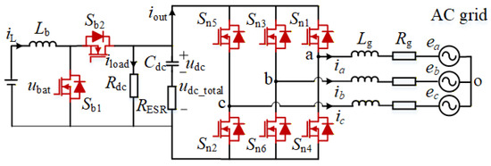
The topology of the BESS is shown in Figure 1, which is combined with a grid-connected inverter and a DC/DC bidirectional converter. In Figure 1, ej, ij (j = a, b, c) are the AC side voltage and current, and Cdc is the capacitor responsible for voltage regulation on the DC side. The left side of the capacitor is the bidirectional DC/DC converter section, and the right side is the AC/DC inverter section. In the converter section, ubat is the voltage of the energy storage battery, Lb is the inductance in the bidirectional DC/DC converter connecting the energy storage side and the inverter side, iL is the output current of the energy storage battery; Sb1 and Sb2 are the switching transistors of the bidirectional DC/DC converter, and their on/off states are responsible for the mode switching of the converter. In the inverter section, Sn1–Sn6 are the six switching transistors on the inverter side; Lg is the AC inductance on the inverter side; Rg is the equivalent resistance on the inverter side; iout is the current on the DC side of the inverter; iload is the load current on the DC side of the inverter; udc is the capacitor voltage; RESR is the ESR of the DC link capacitor; udc_total is the total capacitance voltage after considering the equivalent series resistance (ESR) of the DC link capacitor.
Figure 1.
Topology of the BESS.
2.2. Mathematical Model
According to Figure 1, the mathematical model of the AC side of the BESS is shown as follows:
where Ujo (j = a, b, c) is the AC side output voltage.
The Clark transformation matrix with equal amplitude obtained is as follows:
For the convenience of subsequent design, perform a Clark coordinate transformation on (1); the dynamic equation of the AC side in the αβ coordinate system can be obtained, as follows:
where eα, eβ are the AC side voltage of α, β axis; iα, iβ are the AC side output current of α, β axis; Uα, Uβ are the AC side output voltage of α, β axis.
The mathematical model of the DC side can be expressed as follows:
where da is the duty cycle of the DC-DC converter switching transistor.
3. The MPC-Based Control Method Considering DC Side Voltage Fluctuation Suppression
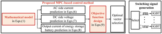
The control block diagram of the MPC-based control method is shown in Figure 2, which can be described by mathematical model construction, system key variable prediction, objective function construction, optimal vector selection, and switching signal generation.
Figure 2.
Control block diagram of the proposed method.
3.1. Discrete Prediction Equation
This study discretizes the dynamic equations of the system based on the first-order Euler forward differential equation. The first-order Euler forward differential equation is shown as follows:
Based on the above equation, discretize Equations (3) and (4) to obtain the prediction equations for the AC side output equation, DC side capacitor voltage, and energy storage battery output current, as follows:
3.2. Cost Function Design
Simultaneously control the output current of the AC side, the capacitor voltage of the DC side, and the output current of the energy storage battery, and construct a unified cost function. To further ensure control accuracy and system safety, an error hard constraint pre-screening mechanism is introduced in the cost function calculation. When traversing 16 switch states, if any prediction error exceeds the limit, the cost function of that state is directly assigned a maximum value to exclude its participation in optimization. The cost function value is only calculated normally when all error terms are within the threshold. This mechanism ensures that MPC only selects the optimal solution in error-controllable states, which improves control reliability without adding additional computational burden, as follows:
where ω1 is the weight coefficient of the AC side output current error control term; ω2 is the weight coefficient of the DC side capacitor voltage error control term; ω3 is the weight coefficient of the energy storage battery output current error control term; , , , and are the reference values for the α and β axis components of the AC output current, the reference value for the DC capacitor voltage, and the reference value for the output current of the energy storage battery, respectively; and are the limits of the α and β axis current error term, respectively; and are the limits of the DC capacitor voltage and battery current error term, respectively.
3.3. Overall Control Flow Chart
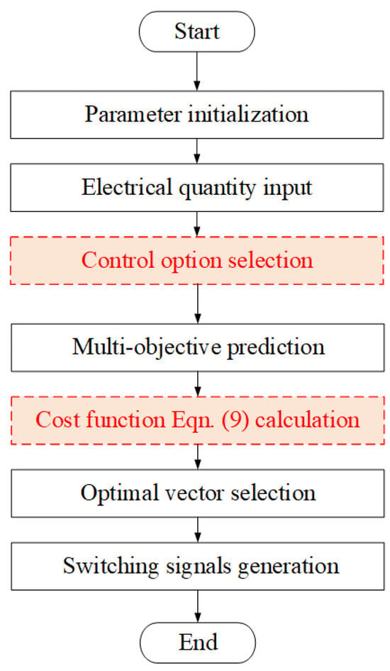
The overall control flow chart is shown in Figure 3, which can be described by the following steps.
Figure 3.
Flow chart of the proposed method.
Step 1: Parameter initialization: Load preset control parameters (e.g., weight coefficients, constraints) to provide a foundational configuration for subsequent calculations, ensuring algorithm reproducibility.
Step 2: Electrical quantity input: Collect real-time electrical system data (e.g., voltage, current, power), which serves as the primary basis for control decisions.
Step 3: Control option selection: Select control options to define the computational objectives for subsequent steps.
Step 4: Multi-objective prediction: Predict future system behavior based on the current state and evaluate potential impacts of different control actions.
Step 5: Cost function calculation: Dynamically compute multi-objective cost values using prediction results, quantifying comprehensive performance metrics.
Step 6: Optimal vector selection: Solve for the control vector corresponding to the minimum cost to generate theoretically optimal control commands.
Step 7: Switching signals generation: Convert theoretical vectors into drive signals for power electronic devices to ensure executable implementation.
3.4. Theoretical Comparison
Theoretical comparison of different MPC methods is shown in Table 1.
Table 1.
Theoretical comparison of different MPC methods.
From Table 1, it can be seen that Reference [27] only takes AC output current as the control objective, without setting DC side voltage limit, and adopts a single MPC framework. The control objective of reference [28] covers the DC side voltage and AC output current, but there is no DC side voltage limitation. A composite framework of active disturbance rejection control based on outer loop voltage control and inner loop current control based on MPC is adopted, which limits the dynamic response speed of the control. Reference [29] takes battery SOC as the control objective, with DC side voltage limitation, and adopts a single MPC framework. In contrast, the control objectives of the control method proposed in this article are more comprehensive, covering DC side voltage, energy storage battery output current, and AC output current. DC side voltage limitation is also set, and an integrated MPC framework is adopted, which demonstrates better comprehensive characteristics in multi-objective collaborative control and system constraint management.
3.5. Computation Burden Analysis
The computational burden of the proposed strategy is verified through theoretical analysis, simulation validation, and real-time discussion to achieve feasibility. For the BESS with a DC/AC two-level converter structure, the total number of feasible switch states is 16. Simulation tests based on MATLAB/Simulink (Intel Core i9-14900HX CPU, 16GB RAM) show that the average computation time of the single control cycle algorithm is 0.0175 ms. Combined with the engineering level maximum allowable computation time constraint of 0.05–0.08 ms for power electronic controllers at a sampling frequency of 10 kHz, the proposed strategy’s computation time meets the hardware processing capability requirements.
4. Simulation Results
Based on MATLAB/SIMULINK, we simulated and analyzed the scene shown in Figure 1, with parameters as shown in Table 2.
Table 2.
Circuit model parameters.
4.1. Selection of Weight Coefficients
In the research on multi-objective weight optimization of model predictive controllers, a particle swarm optimization (PSO) algorithm is designed in this paper to accurately select and quantify the impact of weight coefficients on system performance. Set the weight coefficient of the control term for the output current error on the AC side as the reference value. The optimization process of the weight coefficient optimization algorithm is as follows.
- (1)
- Step 1: Parameter initialization. The parameters of the algorithm need to be initialized, including the number of weight coefficients , inertia weight , self-learning and group-learning factor ,
- (2)
- Step 2: Weight coefficients update and parameter collection from Simulink. Update the values of weight coefficients and process their boundaries so that their values do not exceed the boundary values. The method by which each control parameter updates its speed and position can be expressed as follows:
The simulation is run to obtain the actual values of the capacitor voltage and the energy storage battery output current, and the results are recorded. Parameters adopted by the algorithm are shown in Table 3.
Table 3.
Weight coefficient selection algorithm parameters.
- (3)
- Step 3: Objective function calculation. Carry on adaptive mutation using inertia weight and calculate the fitness.
- (4)
- Step 4: Individual historical best fitness. Compare the fitness of the current particle with the historical best fitness , and update the historical best fitness of the particle according to the comparison result.
- (5)
- Step 5: Weight coefficients with best fitness selection. Compare the fitness of the selected particle in step 4 with the historical best fitness for the whole population, and update the historical best fitness for the population according to the comparison result. The best fitness for the population is obtained after the iteration process as the optimization result, and the corresponding particle position is the optimized value of each weight coefficient.
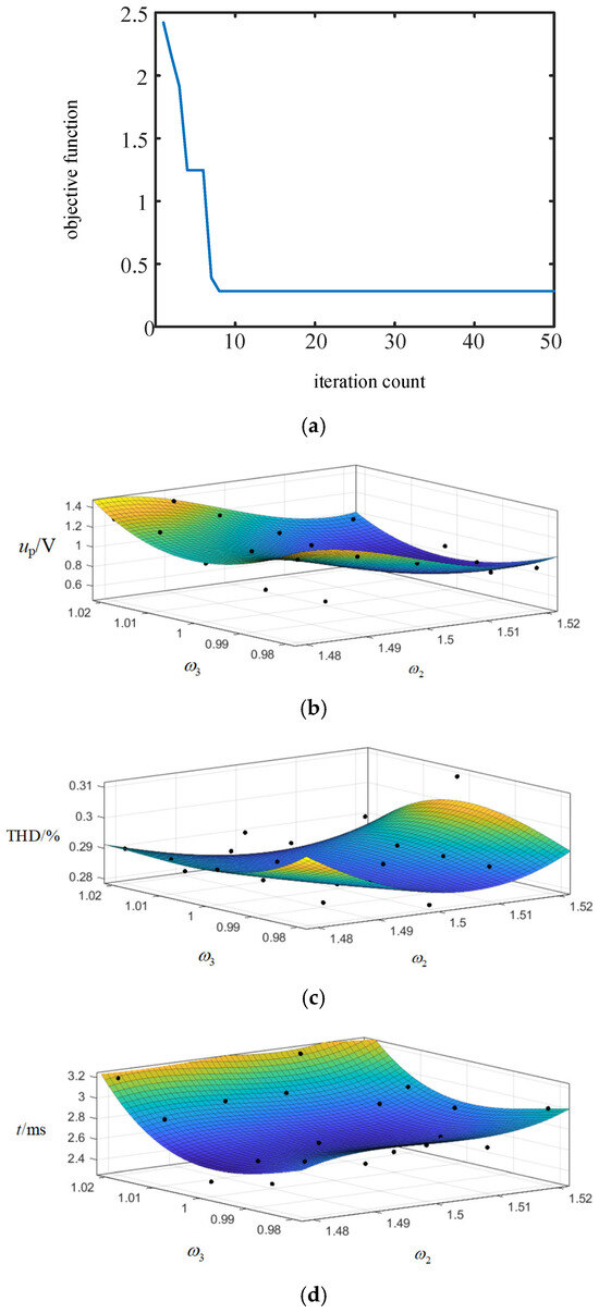
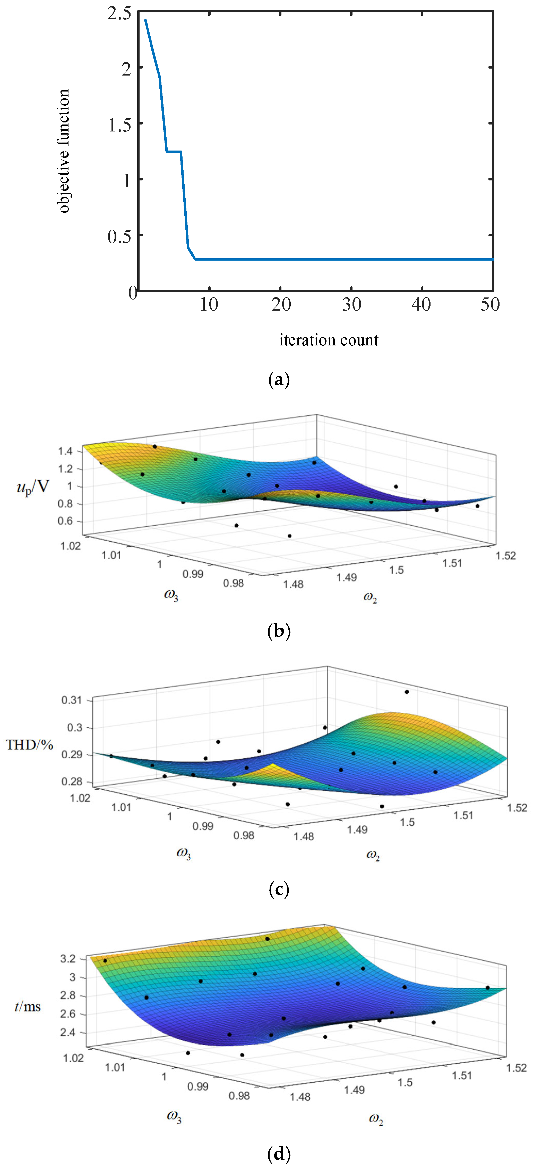
The optimization result is shown in Figure 4a, and the corresponding weight coefficients of ω2 and ω3 are 1.5 and 1, respectively.
Figure 4.
Optimization result: (a) convergence process; (b) sensitivity analysis for DC-link voltage ripple; (c) sensitivity analysis for AC current THD; (d) sensitivity analysis for dynamic settling time.
The optimal combination (1, 1.5, 1) is selected for weight coefficients (ω1, ω2, ω3) for the model predictive control system.
To justify the selection of the weighting coefficients ω2 = 1.5 and ω3 = 1 in the PSO tuning objective and to reveal the inherent performance trade-offs, a systematic sensitivity analysis is conducted. A series of weighting coefficient combinations are selected in the vicinity of the optimized values, and the corresponding system performance metrics, including DC-link voltage ripple, AC current THD, and dynamic settling time, are evaluated through simulations.
Based on the discrete data points obtained from these simulations, three-dimensional sensitivity maps are constructed, shown in Figure 4b–d. Continuous fitting surfaces are generated to visualize the quantitative relationship between the weighting coefficients and each performance metric, where the x-axis and y-axis represent ω2 and ω3, respectively, and the z-axis represents the corresponding performance index. The sensitivity analysis confirms that the selected weighting coefficients achieve favorable and stable performance across voltage ripple, current THD, and dynamic response simultaneously.
The three indicators at the selected combination of weight coefficients are basically at the lowest point of the graph.
4.2. Static Performance Verification
Based on the parameters shown in Table 1, the steady-state performance of the system is first verified.
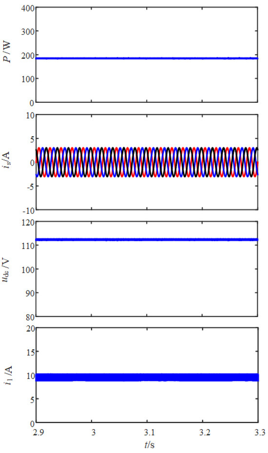
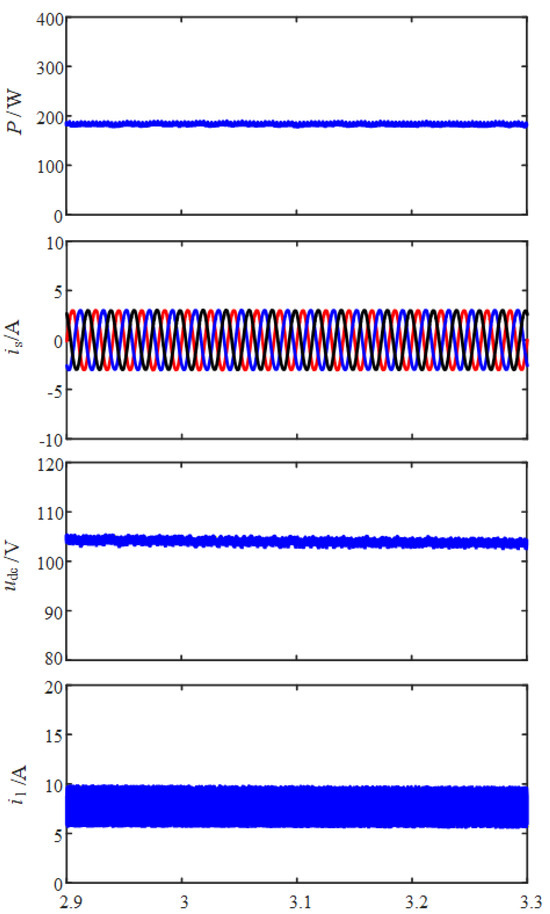
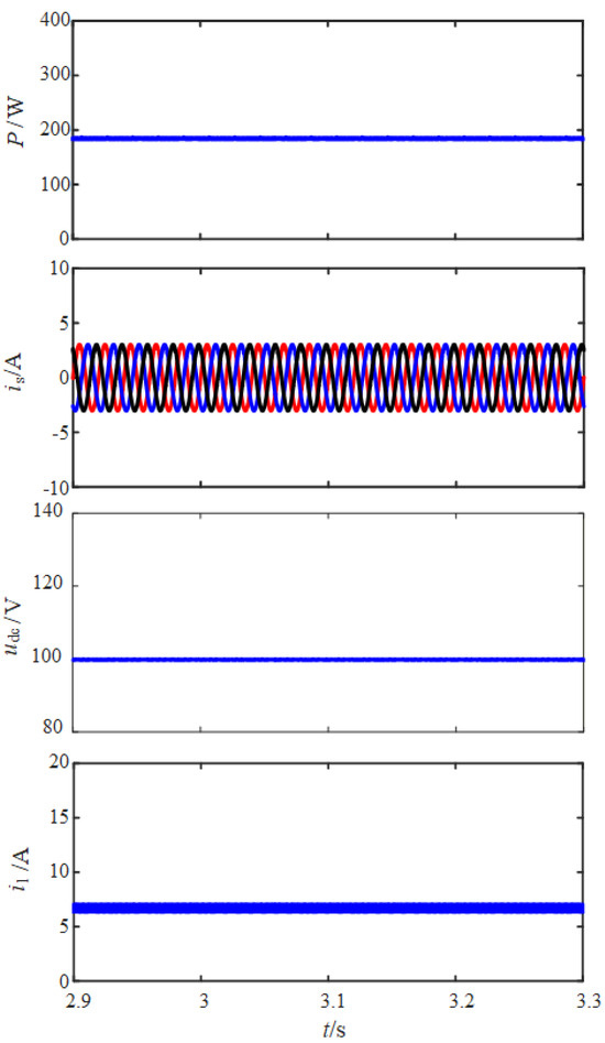
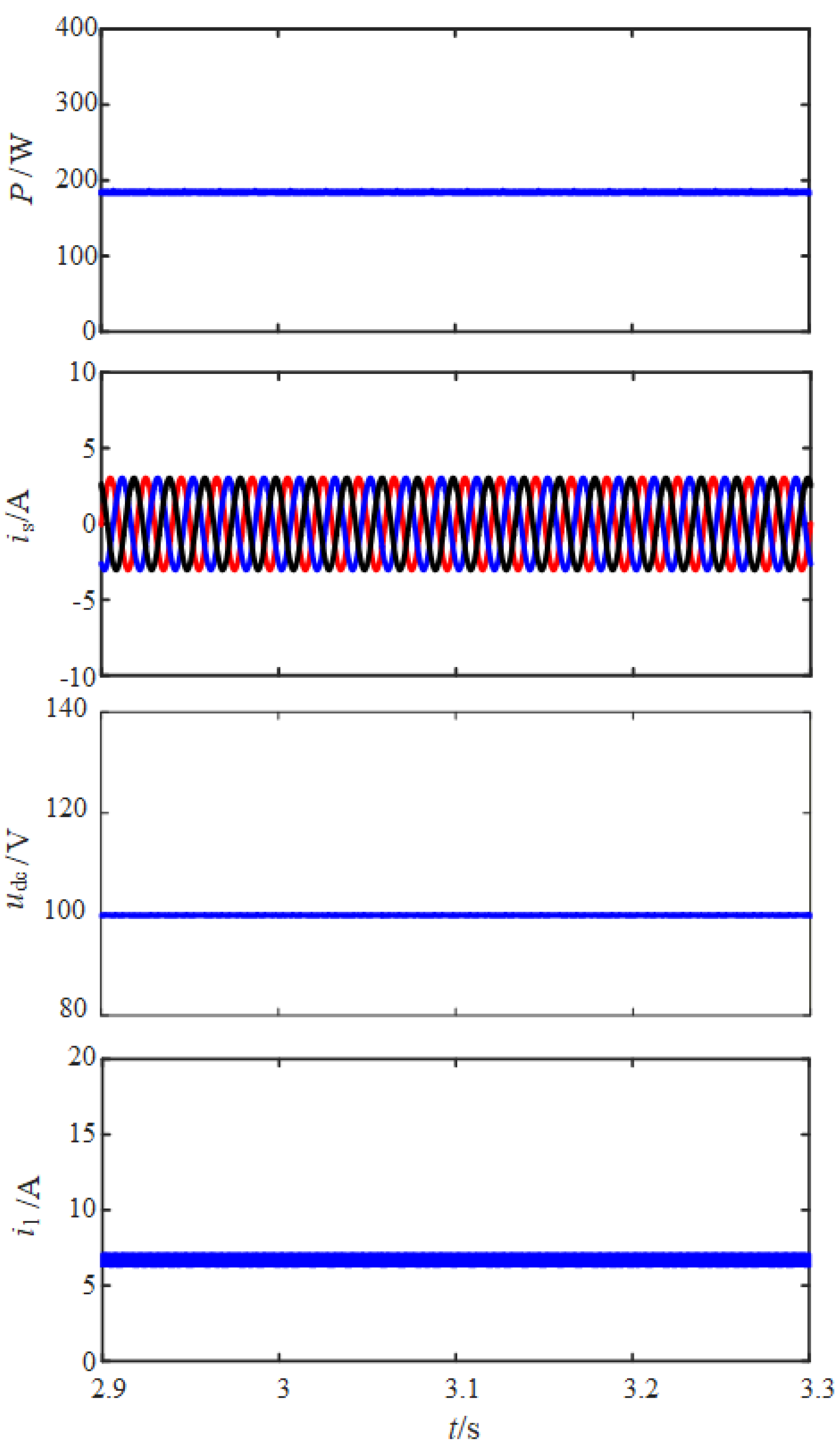
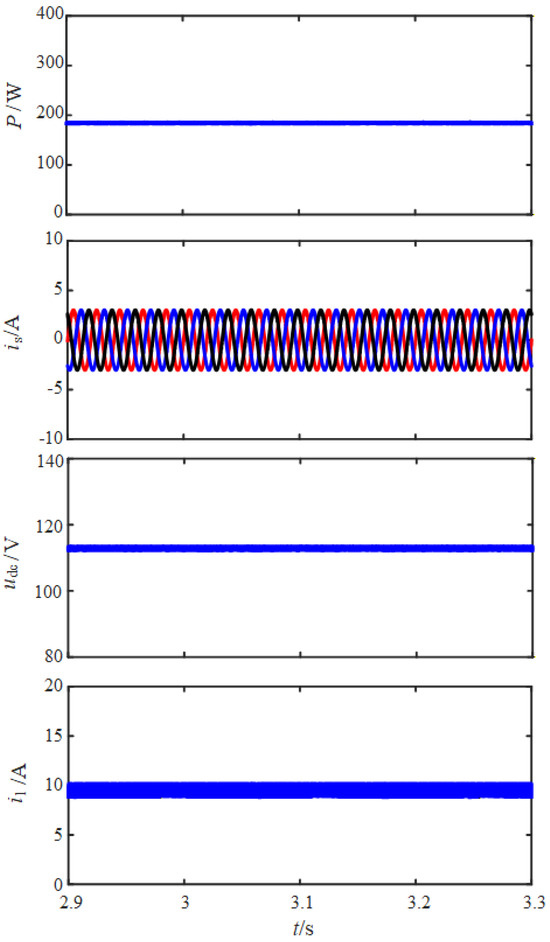
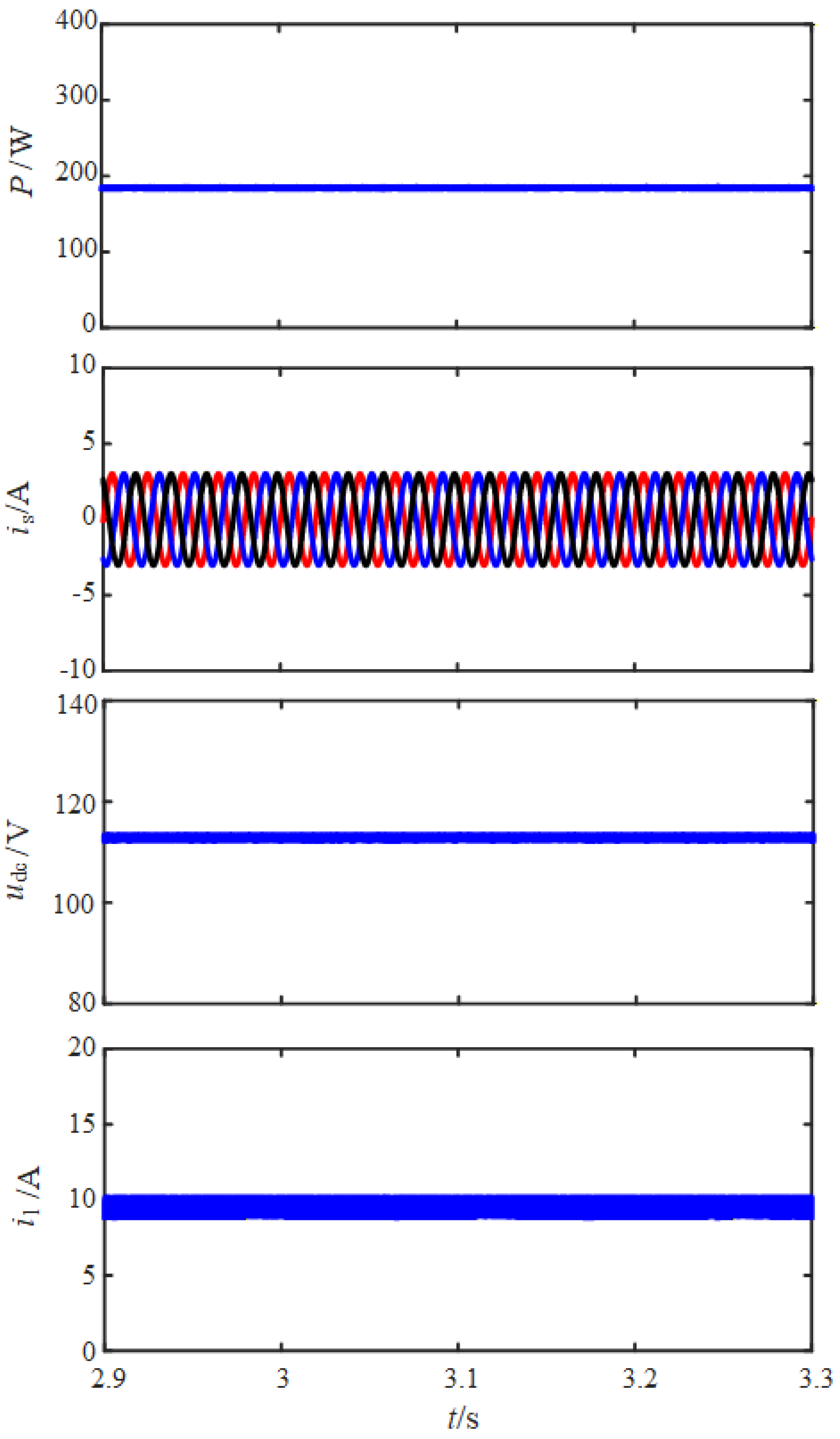
From the simulation results, it can be seen that at the rated operating conditions, the input power on the AC side is close to 186 W, and the system reaches steady state operation. Figure 5, Figure 6, Figure 7, Figure 8, Figure 9 and Figure 10 show the waveforms of AC side power, AC side output current, inverter DC side capacitor voltage, and energy storage battery output current under the proposed control method, PI control, and dual-MPC strategy, respectively. We selected a typical dual-MPC strategy, which separates MPC controllers for the DC/DC and DC/AC stage as the advanced control benchmark, shown in Figure 9 and Figure 10, which adopts exactly the same system configuration, control parameters, prediction settings, and optimization objectives as the proposed method. The only distinction exists in the cost function structure: the dual-MPC separately establishes two independent cost functions for the DC/DC stage and the DC/AC stage, instead of building a unified cost function to realize the collaborative optimization of both stages. The two independent MPC controllers for the AC side and DC side are executed in parallel. No hierarchical priority or sequential decision logic is introduced between the two controllers. Since each regulator operates independently with the same sampling period, no additional latency is introduced by the coordination strategy. All other parameter configurations and control settings are kept completely consistent to guarantee a fair comparison. The two separate cost functions for the DC/DC stage and DC/AC stage are shown as follows:
where the corresponding weight coefficients of ω1, ω2 and ω3 are 1, 1.5 and 1, respectively. The weight coefficients of the proposed method and dual MPC are shown in Table 4.
Figure 5.
Steady−state performance of the proposed strategy with low voltage fluctuation.
Figure 6.
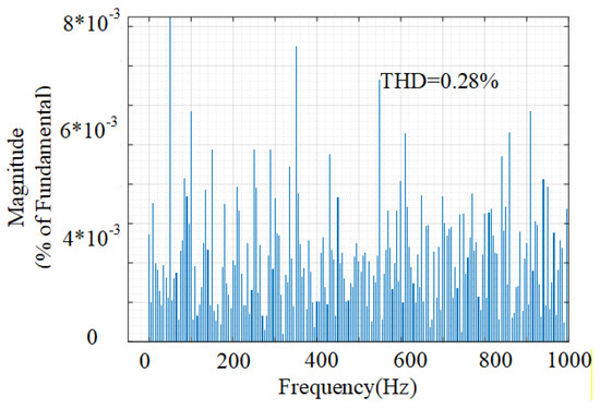
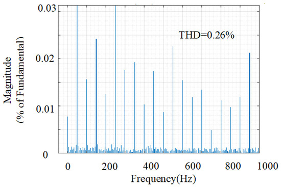
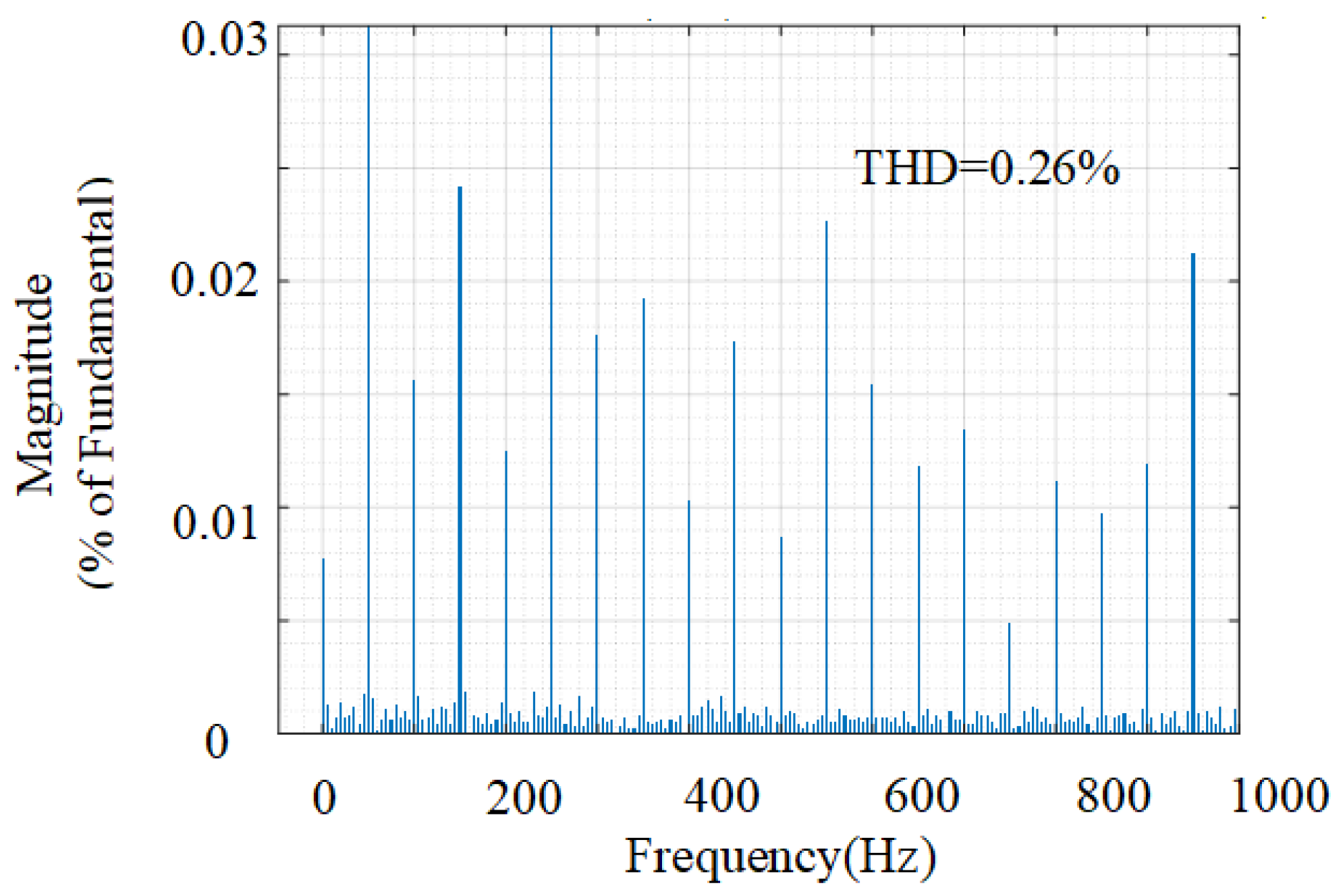
Low THD of the AC output current using the proposed strategy.
Figure 7.
Steady−state performance of the conventional PI strategy.
Figure 8.
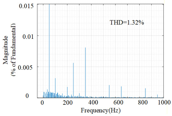
THD of the AC output current using the conventional PI strategy.
Figure 9.
Steady−state performance of the dual-MPC strategy.
Figure 10.
THD of the AC output current using the dual-MPC strategy.
Table 4.
Weight coefficient selection.
Each tracking error term in the cost function is formulated such that all error components maintain a consistent order of magnitude. This ensures that no individual term dominates the optimization objective due to mismatched scales, enabling fair and balanced contributions from all control objectives.
From Figure 5 and Figure 6, it can be seen that the input power waveforms on the AC side under both control strategies are stable without static errors, and remain stable around the command value of 186 W. Both control strategies can achieve rated power factor operation. The total harmonic distortion (THD) of the AC output current under PI control is 1.32%, while under MPC, the THD of the AC output current is reduced to 0.28%. The current waveform under the proposed strategy is closer to a perfect sine wave, with fewer spikes and distortions.
For the DC side capacitor voltage of the BESS, this is one of the core indicators for evaluating control performance.
Under the traditional PI control strategy, the peak-to-peak fluctuation of the udc waveform is about 2.5 V. Under the dual-MPC strategy, the peak-to-peak fluctuation of the udc waveform is about 2.5 V. The proposed strategy suppresses the DC side voltage fluctuation. The peak-to-peak value of voltage ripple is reduced to 0.5 V, which is about 80% lower than that of PI control. The smoother and more stable voltage waveform highlights the effectiveness of the proposed strategy in proactively compensating for voltage fluctuations through predictive terms.
For the output current of the BESS, under traditional PI control, the waveform contains a large number of high-frequency switching harmonic components, with peak-to-peak fluctuations of about 4.5 A. The current smoothness is poor, which is not conducive to the long-term life and system efficiency of the battery. Under the proposed strategy, thanks to the predictive control of battery current, the waveform quality of the output current of the energy storage battery is improved, with a peak-to-peak fluctuation of about 1.3 A, which is about 71.1% lower than PI control. The high-frequency components of the current are effectively filtered out, resulting in a smoother DC waveform. The ripple coefficient of the current is reduced, reducing the stress impact on the energy storage battery. During steady-state operation, although traditional PI controllers can ensure system stability, their response has inherent delays and a limited ability to suppress DC side voltage fluctuations and battery current harmonics. The strategy proposed in this study optimizes the decision-making process of the controller by introducing predictive terms for the DC side capacitor voltage and battery output current. MPC can prospectively calculate the optimal switching state within each control cycle, actively canceling out disturbances instead of passively compensating for errors like PI. The results are reflected in superior power quality: lower AC current THD; a more stable DC bus with reduced DC side voltage fluctuations, improving system stability and reliability; and a smoother battery interface, reducing battery current ripple, which has a positive impact on extending battery life.
4.3. Dynamic Performance Verification
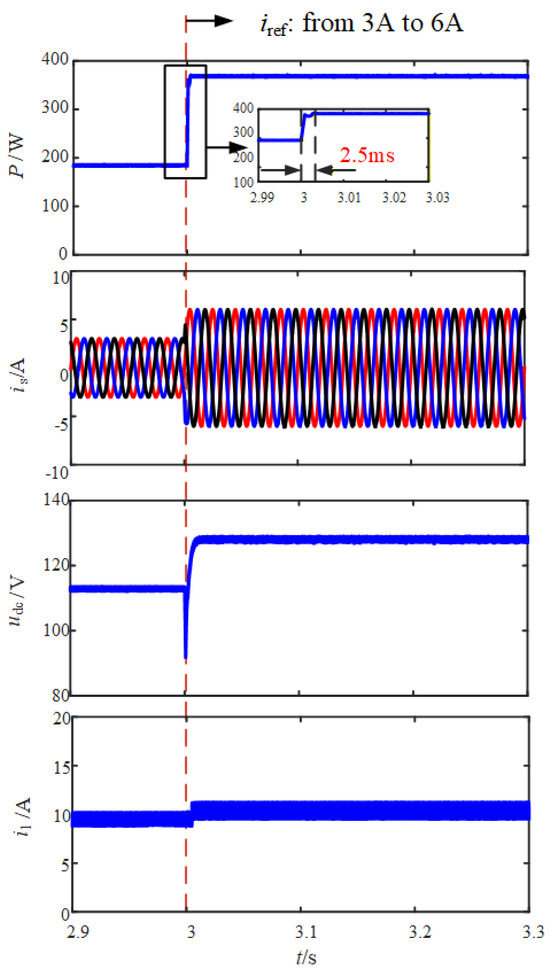
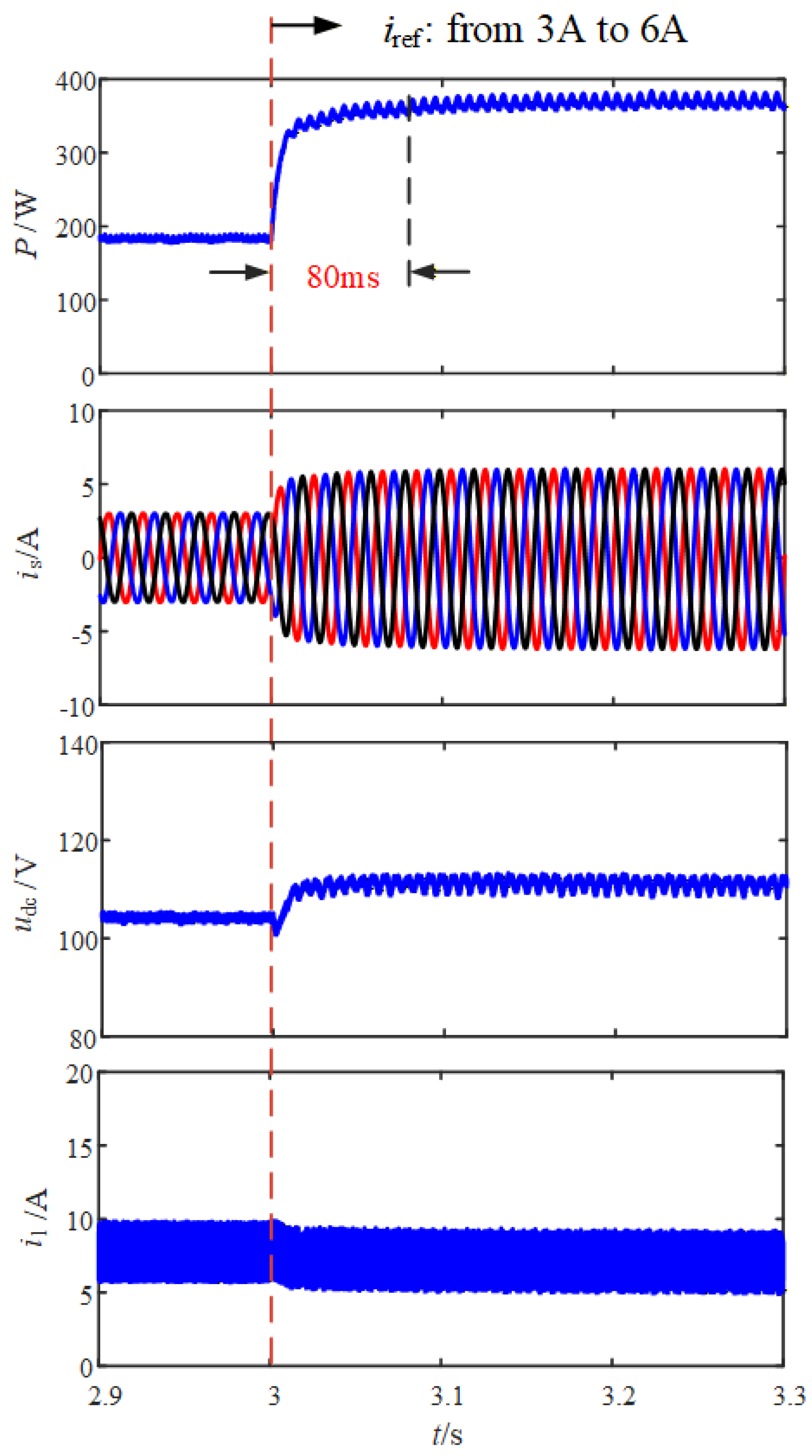
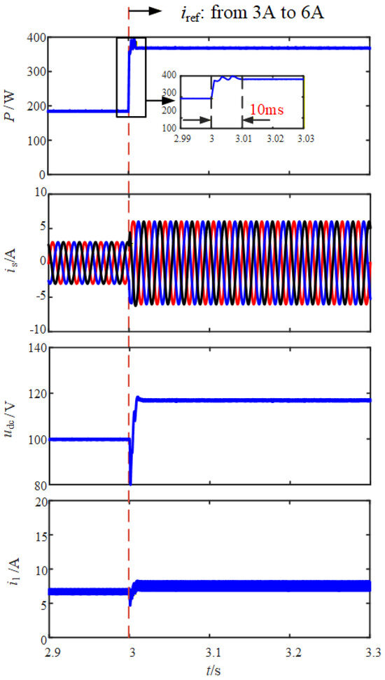
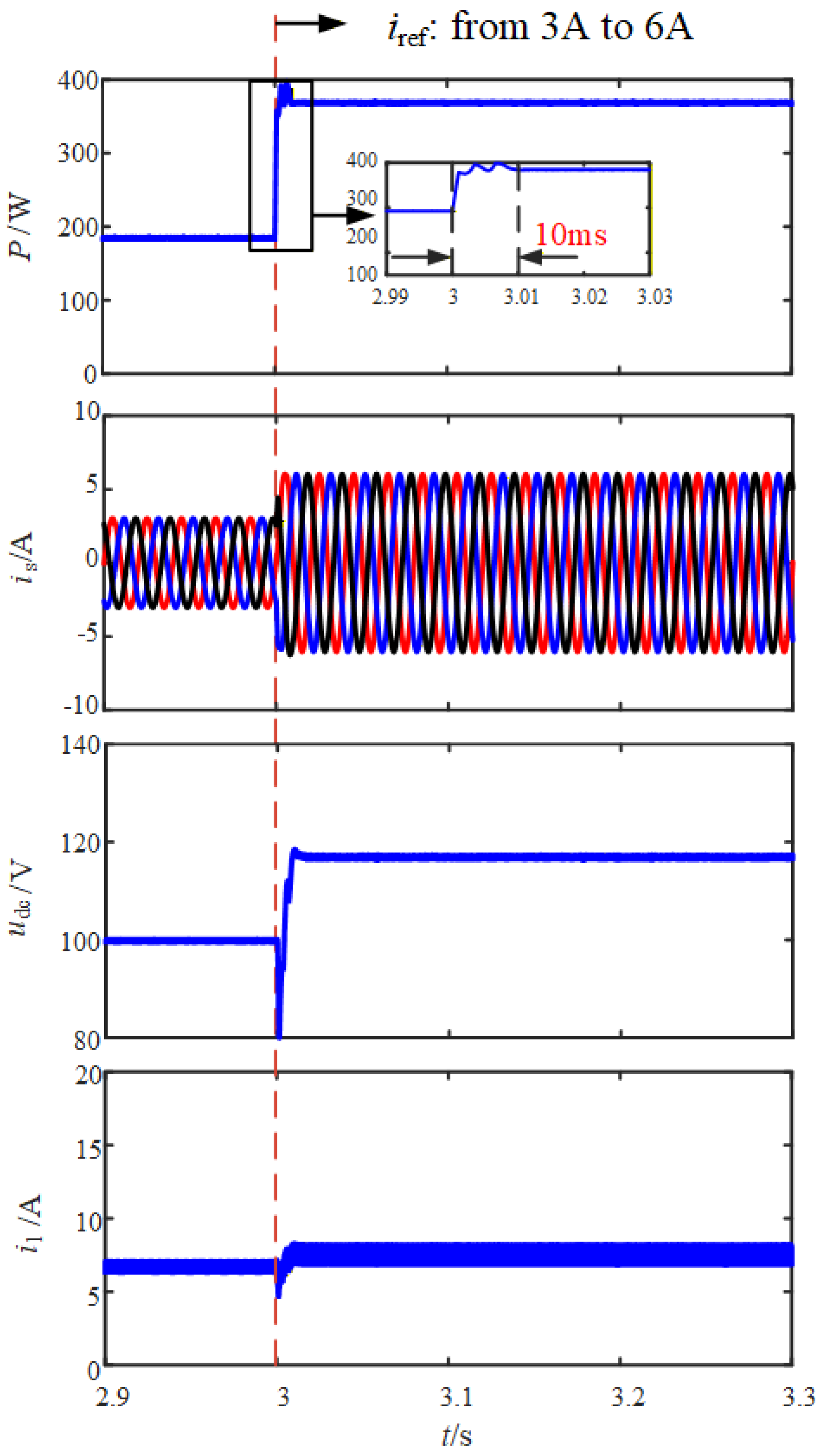
To test the dynamic response of the system, at time t = 3 s, a step change occurred in the AC side power command value, from 186 W to twice its original value. The waveform changes of this transient process are recorded in Figure 11, Figure 12 and Figure 13. From the comparison of power waveforms on the AC side, it can be seen that for traditional PI control, there is a significant adjustment time of about 80 ms for tracking the AC side power, and the power change curve is relatively slow. For the proposed method, MPC exhibits good dynamic performance. The AC side power can quickly track command changes with almost no overshoot, and the adjustment time is shortened to about 2.5 ms, with a response speed much faster than PI control.
Figure 11.
Dynamic performance under the scenario of increased active power using the proposed strategy with fast dynamic response.
Figure 12.
Dynamic performance under the scenario of increased active power using the conventional PI strategy.
Figure 13.
Dynamic performance under the scenario of increased active power using the conventional dual-MPC strategy.
For the output current on the AC side, at the moment of power transition, the amplitude of the output current on the AC side under both controls changes accordingly. Under traditional PI control, the waveform of the output current on the AC side undergoes brief distortion and oscillation during the transient process, and only returns to a stable sine shape after several cycles. Under the proposed method, the current waveform maintains good sinuosity throughout the dynamic process without significant distortion, smoothly transitioning to a new steady state, demonstrating the robustness of MPC.
For the DC side capacitor voltage of the inverter, under traditional PI control, natural frequency oscillation occurs after the capacitor voltage returns to a steady state. This indicates that there is a risk of instability in the system when subjected to large disturbances. Under the proposed method, the system can quickly suppress oscillations, return to steady-state values, and exhibit strong disturbance resistance and stability.
For the output current of energy storage batteries, under traditional PI control, the output current response of energy storage batteries is slow, and there are significant oscillations before and after changes in operating conditions, which is detrimental to both the battery and power devices. Under the proposed method, the dynamic response of the output current of the energy storage battery controlled by MPC is fast and smooth, tracking changes in power demand without overshoot, achieving dynamic protection of the energy storage battery.
In terms of dynamic response time, the dual-MPC method exhibits a dynamic response time of 10 ms during current adjustment, whereas the strategy proposed in this paper achieves a faster response time of 2.5 ms, demonstrating superior dynamic tracking capability. Furthermore, the dual-MPC method exhibits a large DC capacitor voltage overshoot during dynamic processes.
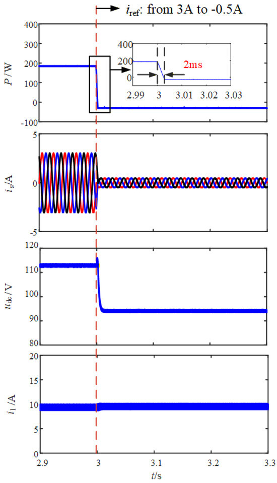
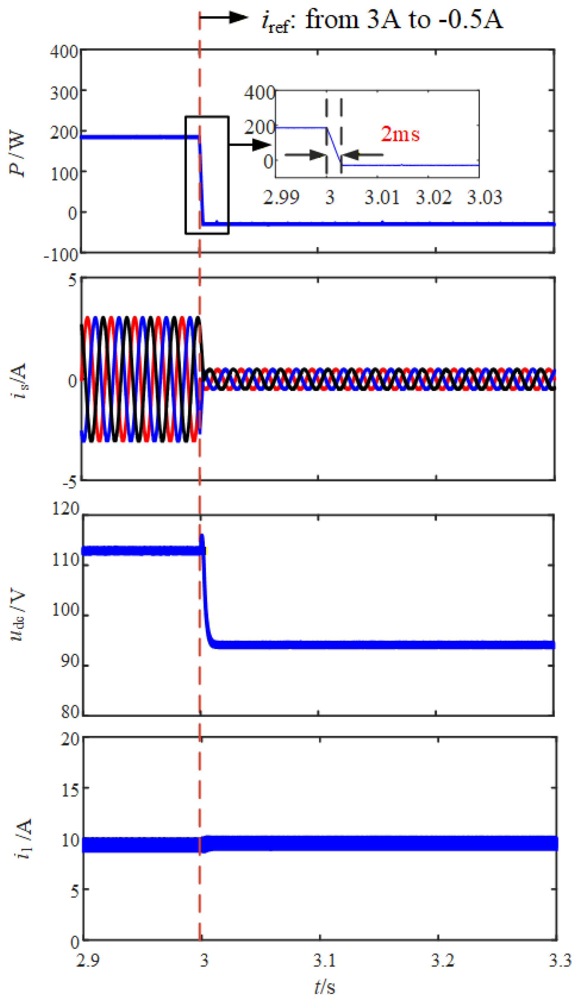
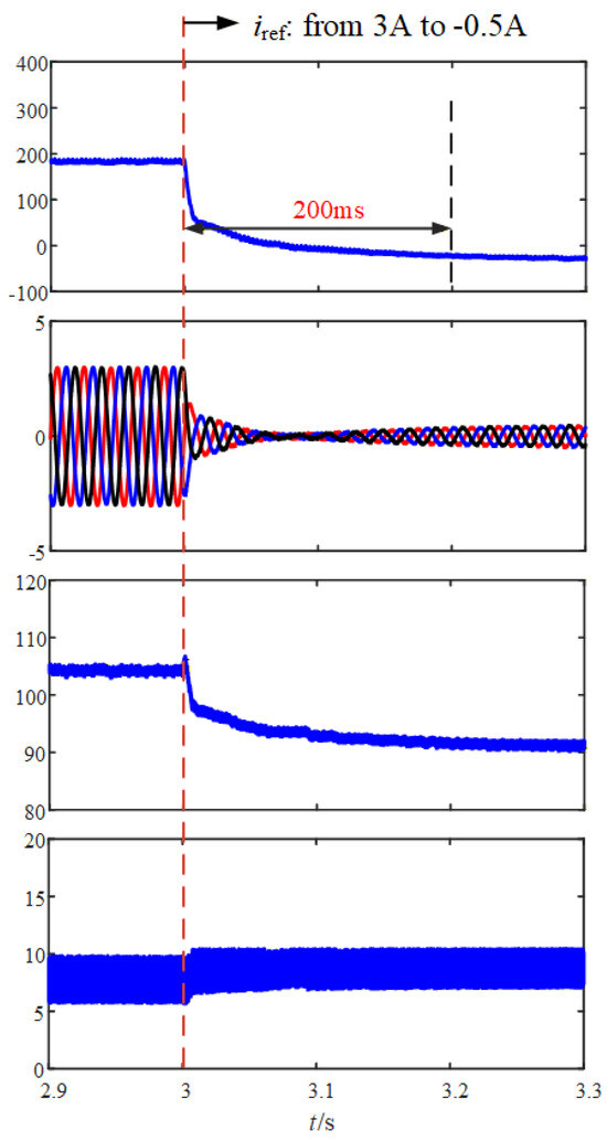
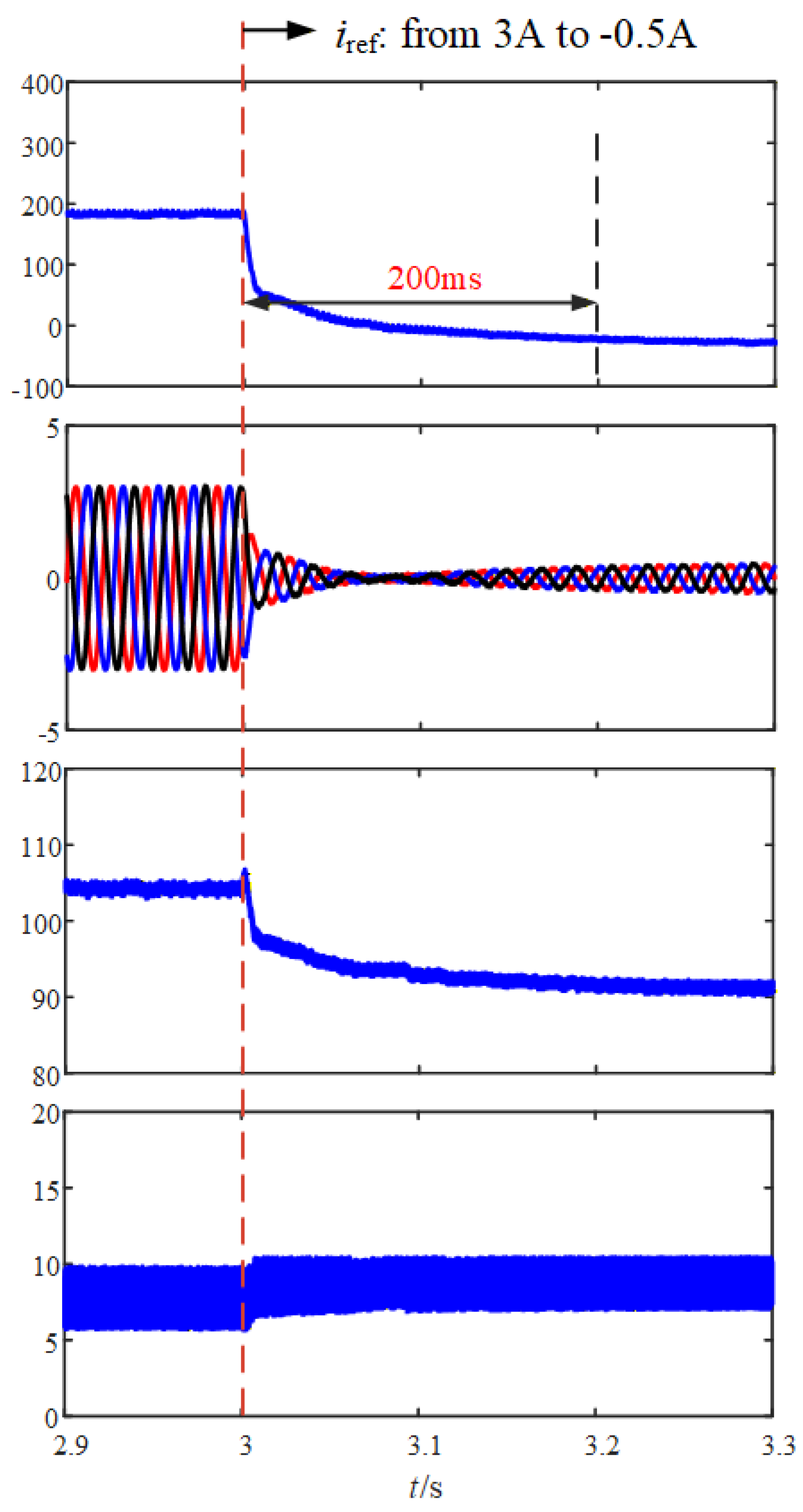
To further test the dynamic response of the system, at time t = 3 s, a step change occurred in the AC side power command value, causing the system power to reverse. The waveform changes of this transient process are recorded in Figure 14 and Figure 15. From the comparison of power waveforms on the AC side, it can be seen that for traditional PI control, there is a significant adjustment time of about 200 ms for tracking the AC side power, and the power change curve is relatively slow. For the proposed method, MPC exhibits good dynamic performance. The AC side power can quickly track command changes with almost no overshoot, and the adjustment time is shortened to about 2 ms, with a response speed much faster than PI control.
Figure 14.
Dynamic performance under the scenario of trend reversal using the proposed strategy with fast dynamic response.
Figure 15.
Dynamic performance under the scenario of trend reversal using the conventional PI strategy.
For the output current on the AC side, at the moment of power transition, the amplitude of the output current on the AC side under both controls changes accordingly. Under traditional PI control, the waveform of the output current on the AC side undergoes brief distortion and oscillation during the transient process, and only returns to a stable sine shape after several cycles. Under the proposed method, the current waveform maintains good sinuosity throughout the dynamic process without significant distortion, smoothly transitioning to a new steady state, demonstrating the robustness of MPC.
For the DC side capacitor voltage of the inverter, under traditional PI control, natural frequency oscillation occurs after the capacitor voltage returns to a steady state. This indicates that there is a risk of instability in the system when subjected to large disturbances. Under the proposed method, the system can quickly suppress oscillations, return to steady-state values, and exhibit strong disturbance resistance and stability.
For the output current of energy storage batteries, under traditional PI control, the output current response of energy storage batteries is slow, and there are significant oscillations before and after changes in operating conditions, which is detrimental to both the battery and power devices. Under the proposed method, the dynamic response of the output current of the energy storage battery controlled by MPC is fast and smooth, tracking changes in power demand without overshoot, achieving dynamic protection of the energy storage battery.
4.4. Robustness Verification
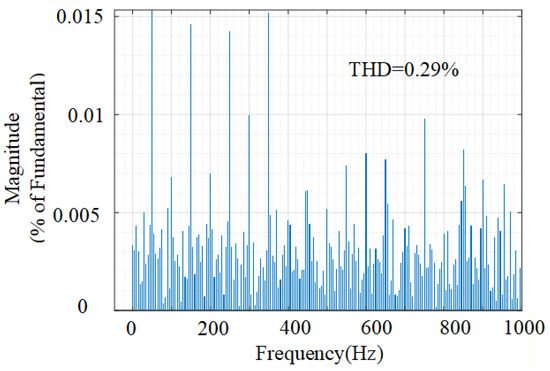
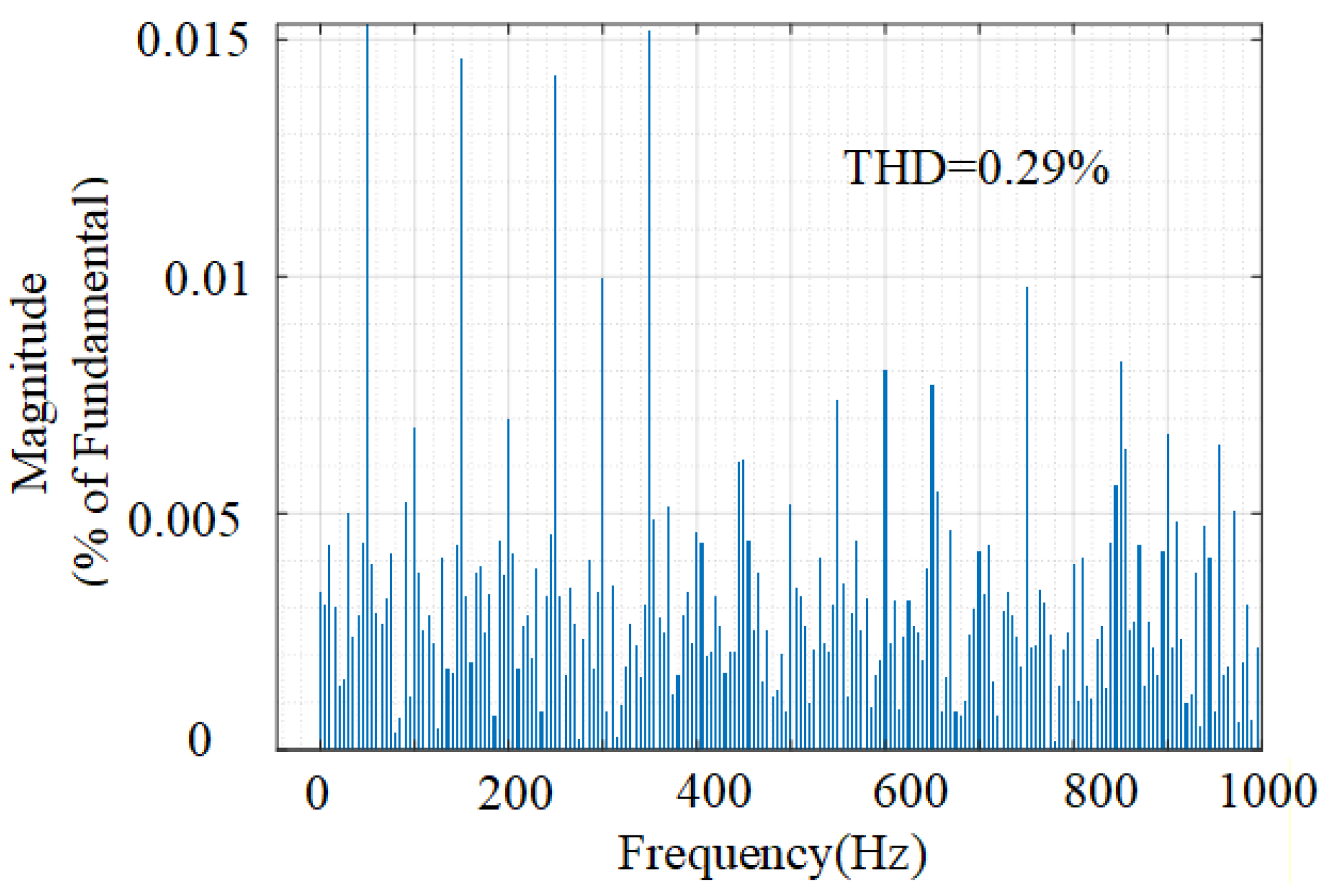
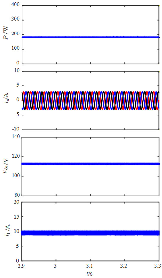
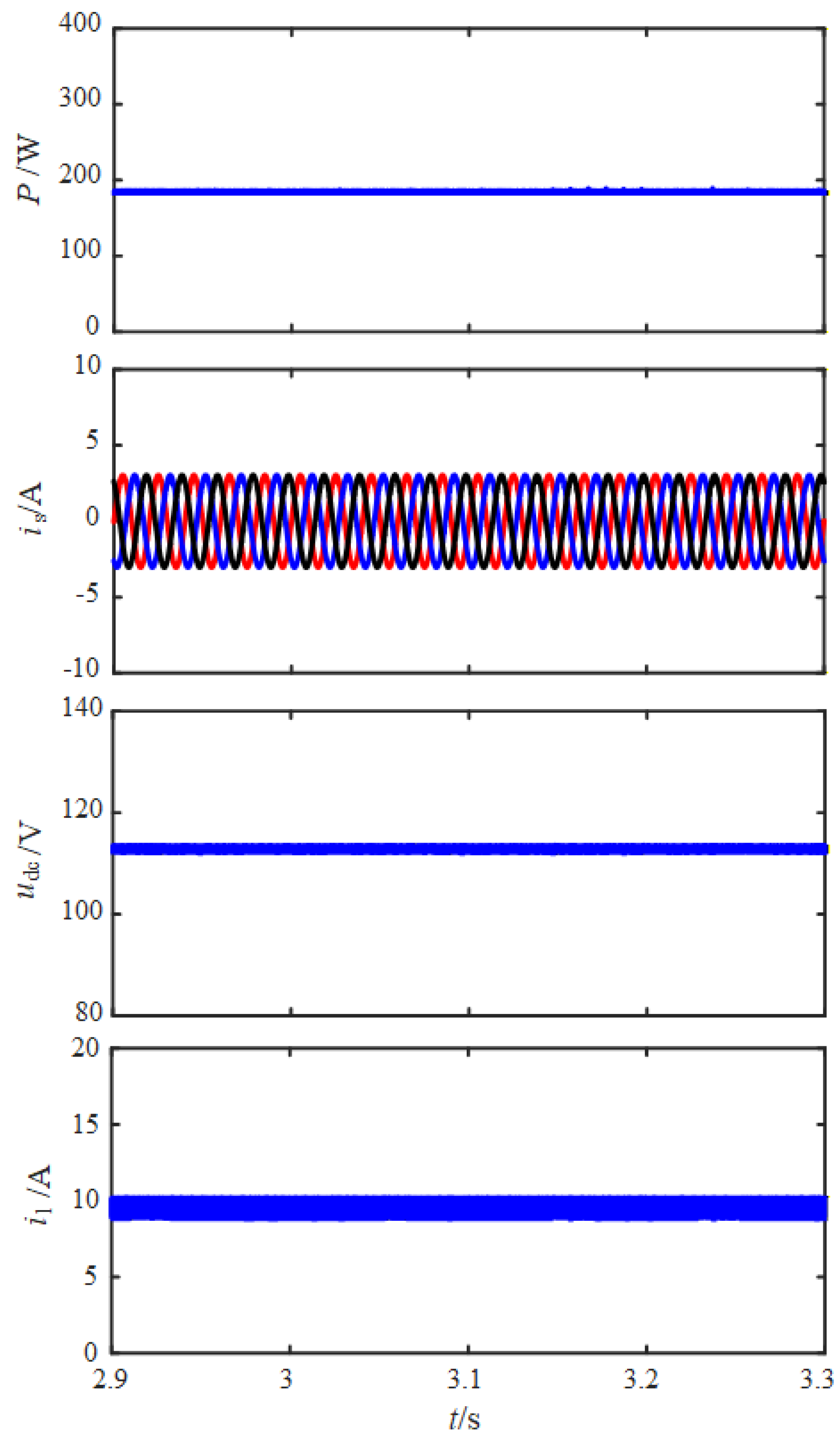
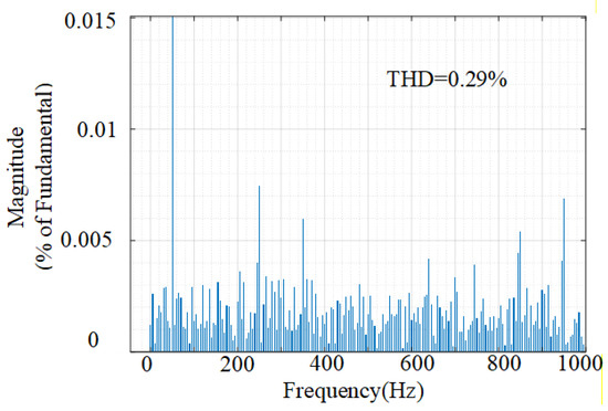
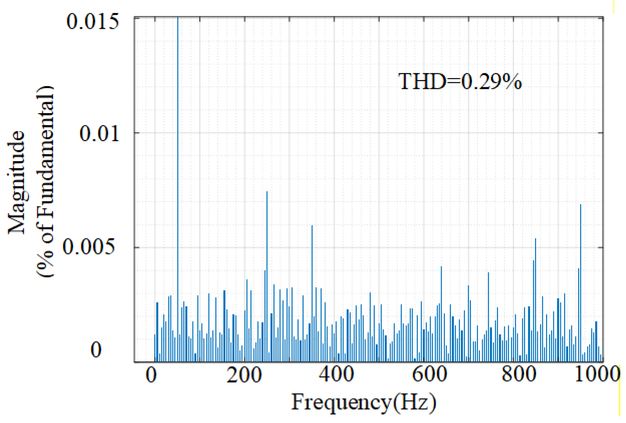
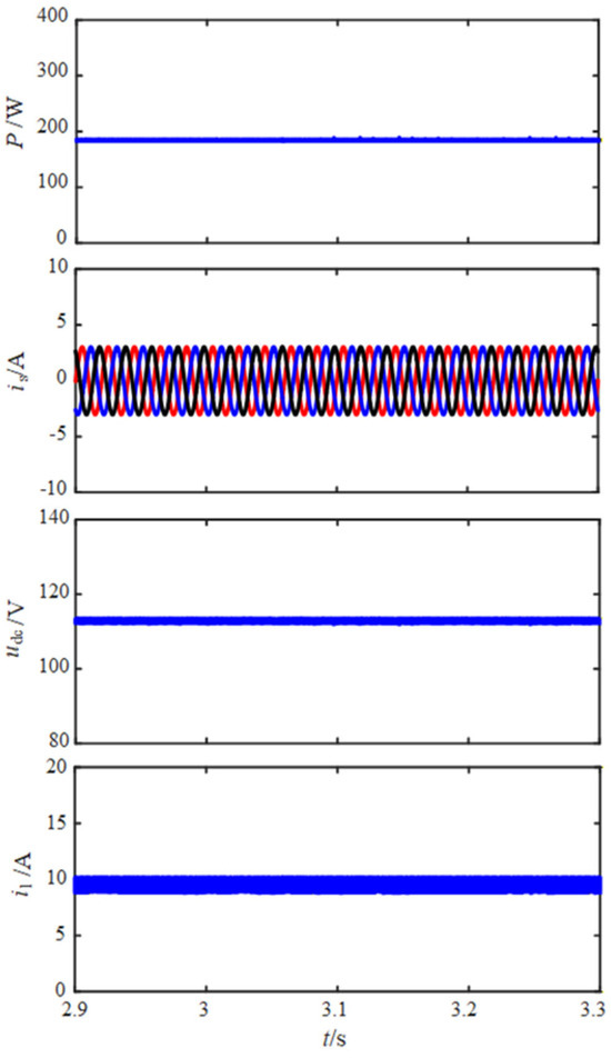
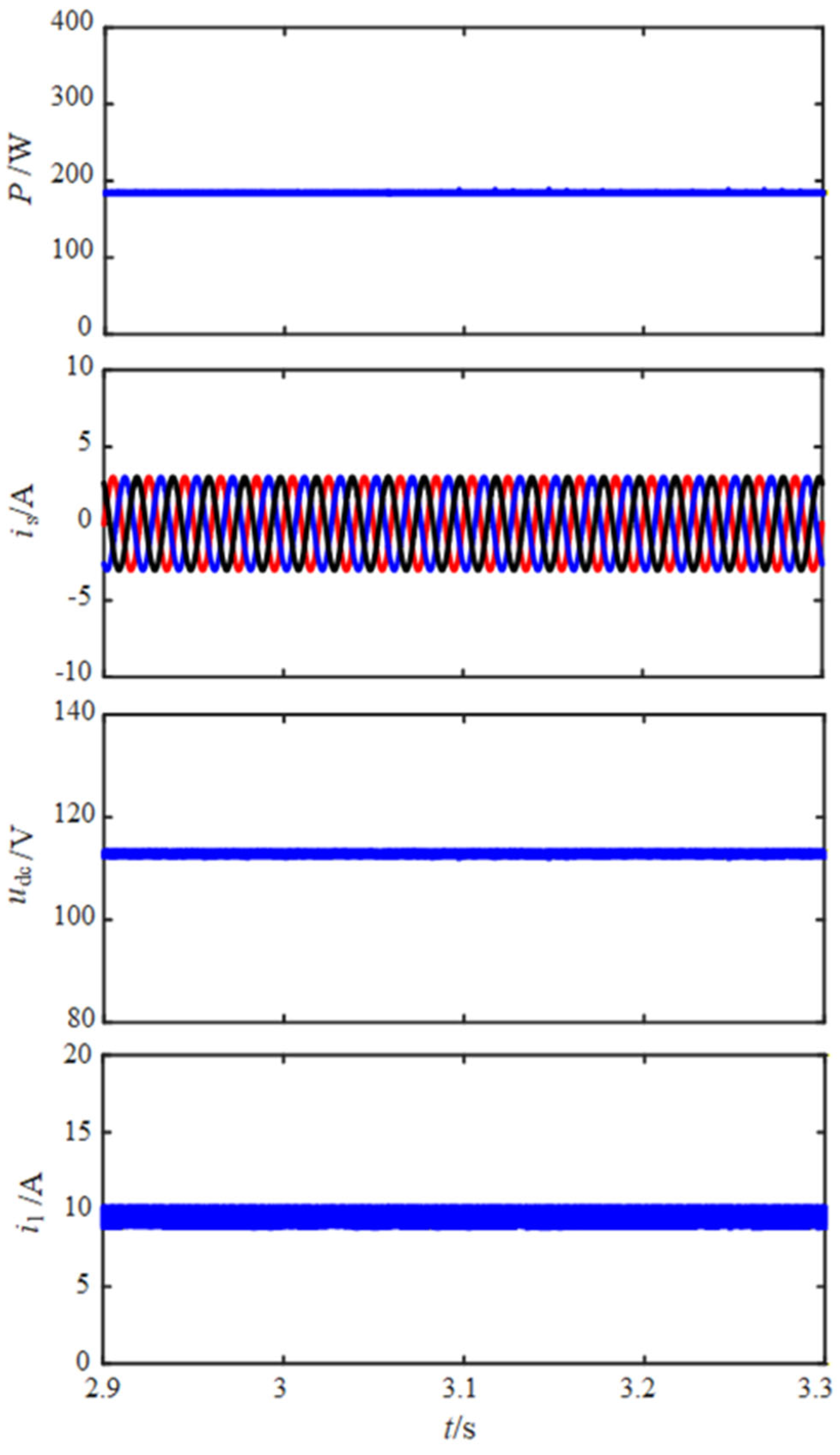
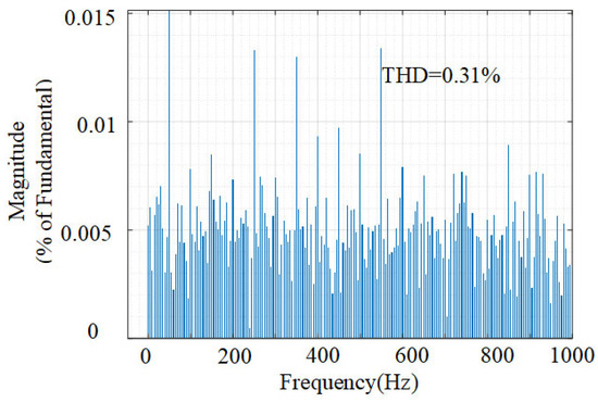
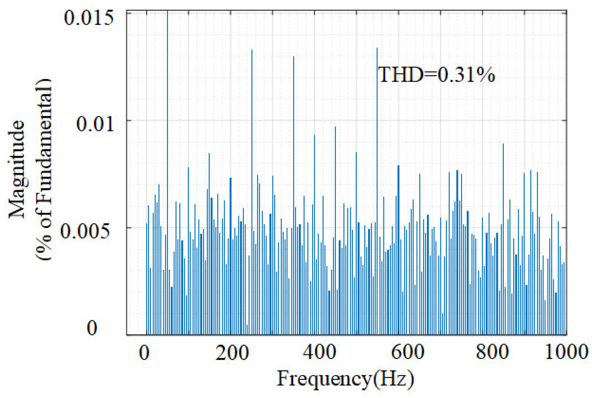
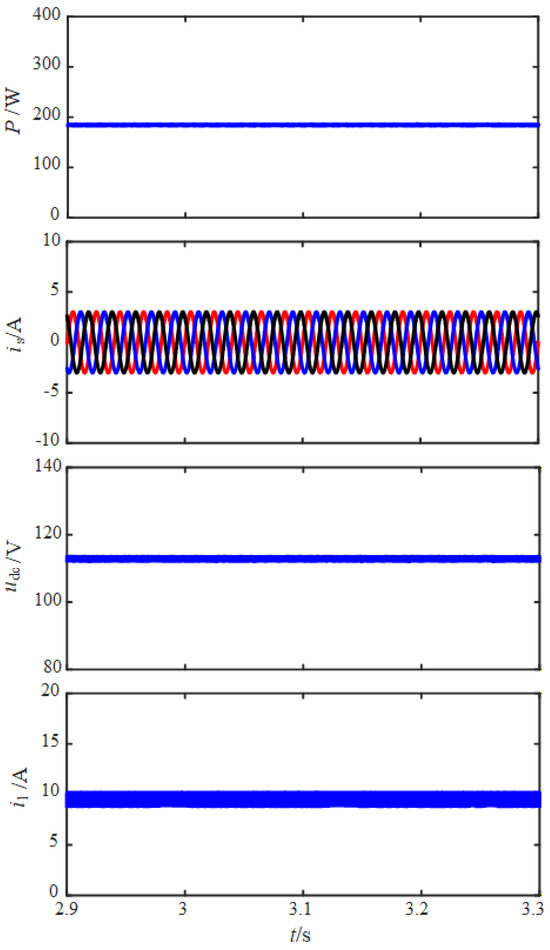
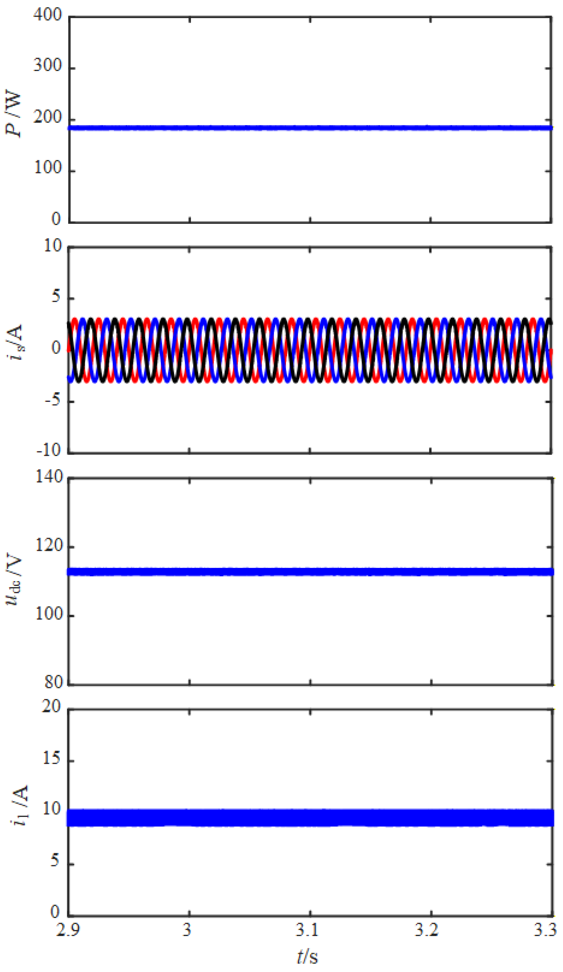
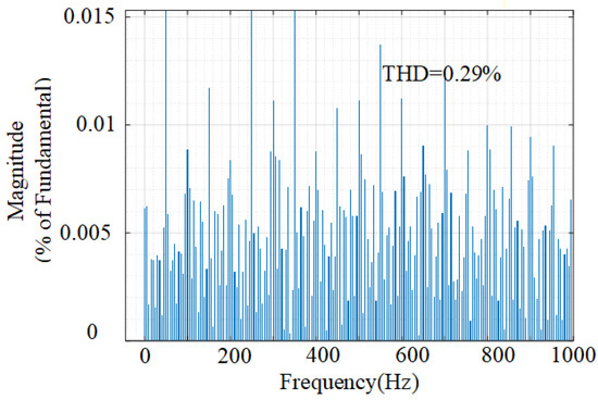
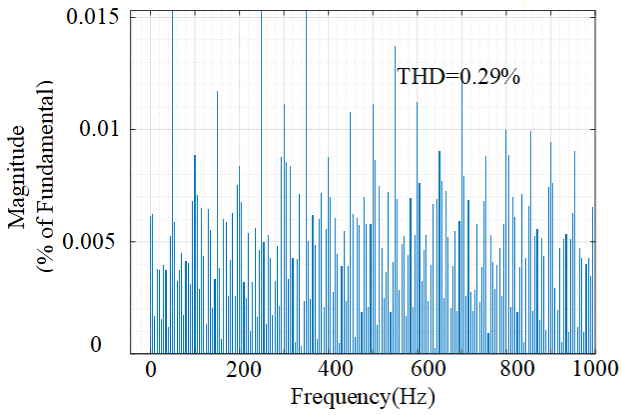
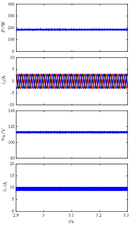
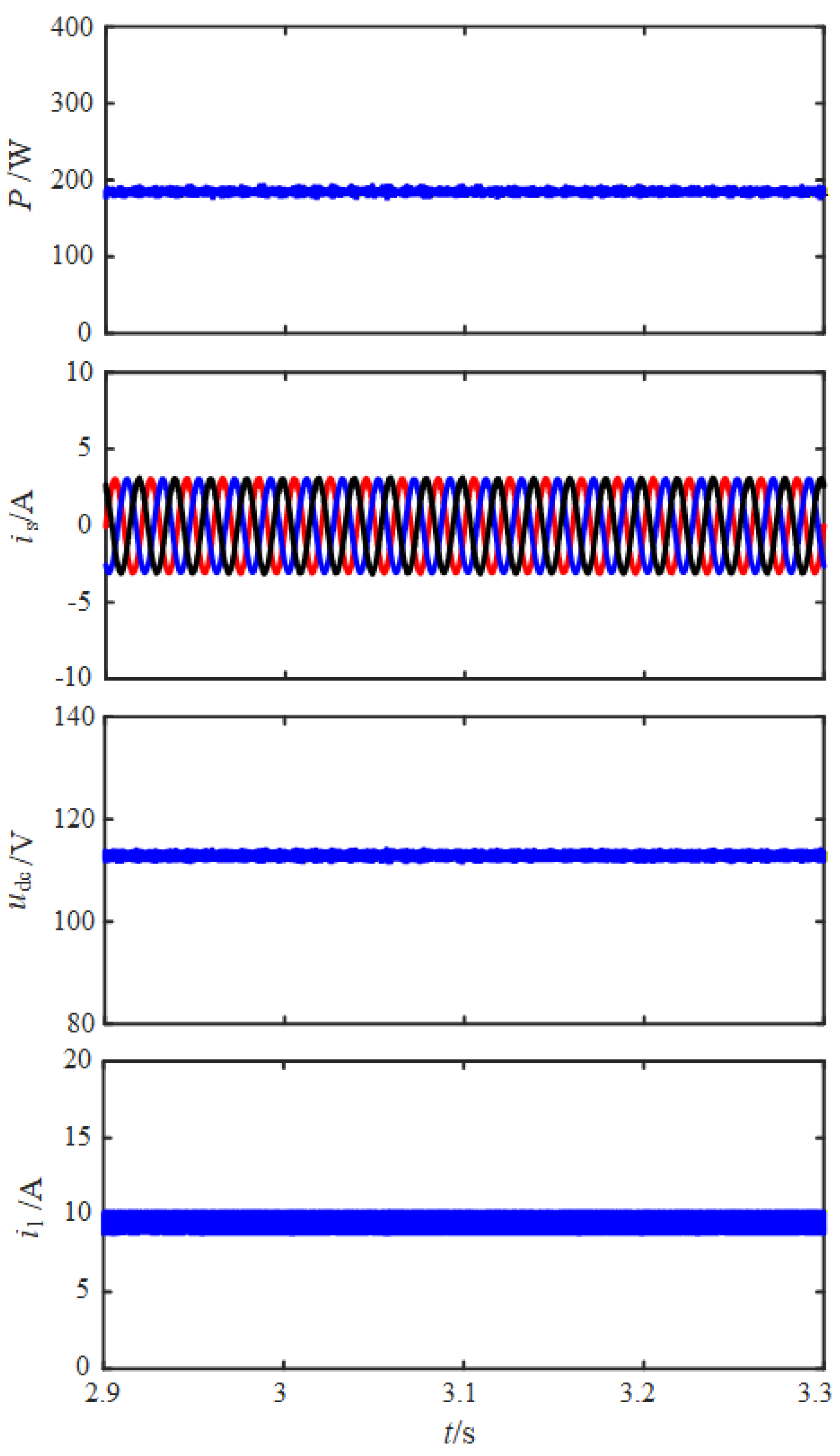
For parameter variations, we conducted simulations under parameter variation in key components, shown in Figure 16, Figure 17, Figure 18, Figure 19, Figure 20, Figure 21, Figure 22 and Figure 23. We adjusted the DC link capacitance from 200 μF to 210 μF, with a deviation of 5%. The results show that even under these parameter deviations, the proposed strategy still maintains stable operation: the DC link voltage fluctuation remains ≤1.5 V, the THD of the AC current is 0.29%, and there is no instability or significant performance degradation. This confirms that the controller has robustness in the face of parameter variation in practical engineering scenarios. Then, we adjusted the ESR from 50 mΩ to 52.5 mΩ, with a deviation of 5%. The results show that even under this parameter deviation, the proposed strategy still maintains stable operation: the DC link voltage fluctuation remains ≤1.5 V, the THD of the AC current is 0.29%, and there is no instability or significant performance degradation. Furthermore, we adjusted the filter inductance Lb from 0.75 mH to 0.7875 mH, with a deviation of 5%. The results show that even under this parameter deviation, the proposed strategy still maintains stable operation: the DC link voltage fluctuation remains ≤1.5 V, the THD of the AC current is 0.31%, and there is no instability or significant performance degradation. Finally, we adjusted the grid resistance Rg from 0.97 Ω to 1.0185 Ω and the grid inductance Lg from 0.03 H to 0.0315 H, both with a deviation of 5%. The results show that even under these simultaneous parameter deviations, the proposed strategy still maintains stable operation: the DC link voltage fluctuation remains ≤1.5 V, the THD of the AC current is 0.29%, and there is no instability or significant performance degradation. These results confirm that the proposed control strategy exhibits strong robustness against parameter variations in practical engineering scenarios.
Figure 16.
Steady−state performance of the proposed strategy with low voltage fluctuation under DC link capacitance variation.
Figure 17.
Low THD of the AC output current using the proposed strategy under DC link capacitance variation.
Figure 18.
Steady−state performance of the proposed strategy with low voltage fluctuation under ESR variation.
Figure 19.
Low THD of the AC output current using the proposed strategy under ESR variation.
Figure 20.
Steady−state performance of the proposed strategy with low voltage fluctuation under filter inductance variation.
Figure 21.
Low THD of the AC output current using the proposed strategy under filter inductance variation.
Figure 22.
Steady−state performance of the proposed strategy with low voltage fluctuation under grid resistance and inductance variation.
Figure 23.
Low THD of the AC output current using the proposed strategy under grid resistance and inductance variation.
To characterize the random measurement noise introduced by actual sensors and analog-to-digital conversion modules, a zero-mean Gaussian white noise model is employed in the simulation. The noise is injected at the output of the sampling sensor before the quantization process, which conforms to the physical generation mechanism of measurement noise in practical systems. The root mean square value of the noise is set to one percent of the rated signal amplitude, and the sample time of the noise is consistent with the control sampling period to ensure accurate and reasonable modeling. To obtain reliable statistical characteristics, twenty independent simulation runs are conducted with different random seeds to generate distinct noise sequences while all other system parameters remain unchanged.
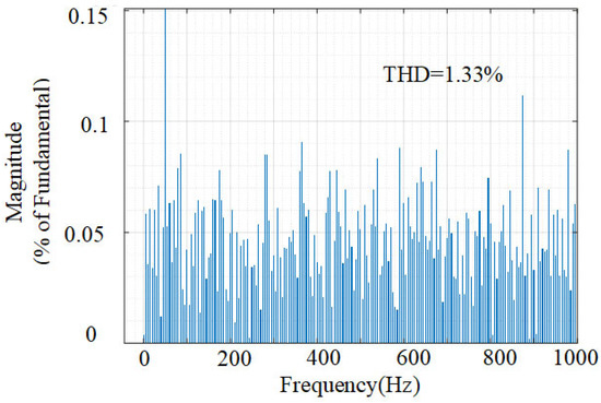
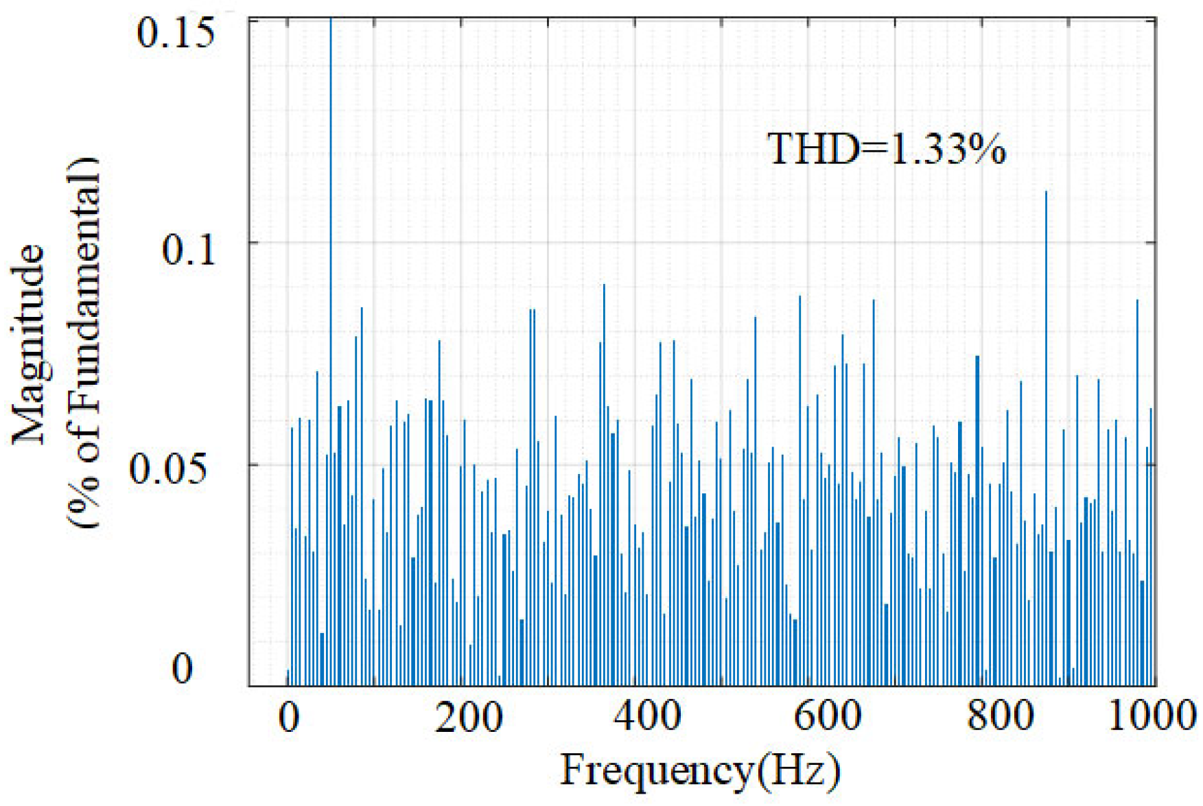
The statistical results obtained from multiple independent simulation runs demonstrate the performance of the system under random measurement noise. The average voltage ripple of the DC link is 2 V, with a standard deviation of 0.15 V and a 95th percentile of 2.2 V. The worst-case voltage ripple is 2.3 V. The total harmonic distortion of the AC current shows an average value of 1.35% and a standard deviation of 0.015%, with a 95th percentile of 1.37% and a worst-case scenario of 1.37%. The average dynamic response time is 3 ms, the standard deviation is 0.06 ms, the 95th percentile is 3.10 ms, and the worst-case scenario is 3.10 ms. Under random noise interference, all statistical indicators remain within a satisfactory range, which verifies that the proposed control strategy has strong robustness and reliability in practical engineering scenarios. The simulated waveform is shown in Figure 24 and Figure 25.
Figure 24.
Steady−state performance of the proposed strategy with low voltage fluctuation under measurement noise.
Figure 25.
Low THD of the AC output current using the proposed strategy under measurement noise.
5. Conclusions
This article focuses on the BESS composed of inverters and bidirectional DC/DC converters, aiming to solve the problem of DC side voltage fluctuations and improve the overall performance and reliability of the system. An MPC objective function that integrates multiple predictive terms of DC side capacitor voltage and battery current is designed, providing a new idea for coordinated control of energy storage converters. The comprehensive advantages of this strategy over traditional PI control in steady-state accuracy, harmonic suppression, dynamic response, and disturbance resistance have been fully verified through simulation. Through comprehensive simulation experiments, the proposed strategy was compared and validated with traditional PI control from both steady-state and dynamic dimensions. The results showed that
- (1)
- In terms of steady-state performance, the proposed MPC-based control strategy demonstrates control accuracy and fluctuation suppression capability. Compared with PI control, MPC can reduce the fluctuation amplitude of the DC side capacitor voltage of the inverter by about 80% in peak-to-peak value, while outputting higher quality AC and DC currents: the total harmonic distortion (THD) of the AC side current is lower, and the waveform is closer to a perfect sine wave. The ripple content of the output current on the battery side is reduced, and the waveform is smoother, effectively reducing the stress impact on the energy storage battery and beneficial for extending its cycle life.
- (2)
- In terms of dynamic performance, the advantages of the MPC strategy are more prominent. When the system power undergoes a step change, MPC exhibits extremely fast dynamic response speed and robustness. Its tracking of AC power commands has almost no overshoot, and the adjustment time is extremely short. More importantly, it can suppress the fluctuation and oscillation of capacitor voltage during dynamic processes, constrain the voltage fluctuation range within a smaller safe range, and achieve rapid recovery, enhancing the stability of the system in dealing with power disturbances.
Author Contributions
Conceptualization, W.C. and Y.J.; Software, B.X.; Validation, H.L. and H.C.; Formal analysis, Q.X.; Investigation, Y.J.; Writing—original draft, P.C.; Writing—review & editing, L.Z., Y.J. and Q.X.; Funding acquisition, Q.X. All authors have read and agreed to the published version of the manuscript.
Funding
The work is funded by the Science and Technology Program of Tianjin, China (24ZXKJGX00040) and the Science and Technology Project of State Grid Tianjin Electric Power Company (Electric Science-S&T Project 2025-13).
Data Availability Statement
The original contributions presented in this study are included in the article. Further inquiries can be directed to the corresponding author.
Conflicts of Interest
Peiyu Chen, Wenqing Cui, Bin Xu and Li Zhang were employed by Electric Power Research Institute, State Grid Tianjin Electric Power Company. The authors declare that this study received funding from the Science and Technology Project of State Grid Tianjin Electric Power Company (Electric Science-S&T Project2025-13). The funder was involved in providing help for parameter confirmation of the studied system and financial support for publication fees of this manuscript.
References
- Lu, W.; Xiao, Q.; Jia, H.; Jin, Y.; Mu, Y.; Zhu, J.; Shen, C.; Teodorescu, R.; Guerrero, J.M. Projected Gradient Descent-Based Dynamic Event-Triggered Optimal Control for MVDC-DS Considering Power Interaction Ability with AC Grid. IEEE Trans. Smart Grid 2025, 16, 4488–4501. [Google Scholar] [CrossRef] [Scilit]
- Zhang, H.; Ye, J.; Hu, X.; Huang, H.; Wu, X.; Xu, Y.; Zhou, Y. Bidirectional carbon emission flow analysis for the high-penetration renewable energy systems with distributed energy resources. Energy Convers. Econ. 2025, 6, 213–224. [Google Scholar] [CrossRef] [Scilit]
- Li, J.; Fang, Z.; Wang, Q.; Zhang, M.; Li, Y.; Zhang, W. Optimal Operation with Dynamic Partitioning Strategy for Centralized Shared Energy Storage Station with Integration of Large-scale Renewable Energy. J. Mod. Power Syst. Clean Energy 2024, 12, 359–370. [Google Scholar] [CrossRef] [Scilit]
- Xiao, Q.; Yu, H.; Jin, Y.; Jia, H.; Mu, Y.; Zhu, J.; Liu, H.; Teodorescu, R.; Blaabjerg, F. Adaptive virtual inertia emulation and control scheme of cascaded multilevel converters to maximize its frequency support ability. IEEE Trans. Ind. Electron. 2025, 73, 3614–3624. [Google Scholar] [CrossRef] [Scilit]
- Meng, L.; Wang, H.; Lu, S.; Yang, Z.; Chen, Z.; Bevrani, H.; Rehimi, S.; Xia, M.; Micu, D.D.; Marquez, F.P.G.; et al. Wide-area damping control in renewable integrated power systems: A review on recent achievements and new challenges. Energy Convers. Econ. 2025, 6, 341–358. [Google Scholar] [CrossRef] [Scilit]
- Guo, S.; Kurban, A.; He, Y.; Wu, F.; Pei, H.; Song, G. Multi-Objective Sizing of Solar-Wind-Hydro Hybrid Power System with Doubled Energy Storages Under Optimal Coordinated Operational Strategy. CSEE J. Power Energy Syst. 2023, 9, 2144–2155. [Google Scholar]
- Lu, W.; Xiao, Q.; Jia, H.; Jin, Y.; Mu, Y.; Zhu, J.; Shen, C.; Teodorescu, R.; Guerrero, J.M. A Projected Gradient Descent-Based Distributed Optimal Control Method of Medium-Voltage DC Distribution System Considering Line Loss. IEEE Trans. Power Syst. 2024, 40, 1751–1763. [Google Scholar] [CrossRef] [Scilit]
- Xiao, Q.; Jia, H.; Tang, Y.; Jin, Y.; Mu, Y.; Teodorescu, R.; Blaabjerg, F. Dual-Layer Modulated Model Predictive Control Scheme for the Cascaded H-Bridge Converter. IEEE Trans. Ind. Electron. 2023, 70, 9751–9763. [Google Scholar] [CrossRef] [Scilit]
- Rasool, S.; Muttaqi, K.M.; Sutanto, D. A Novel Configuration of a Hybrid Offshore Wind-Wave Energy Conversion System and Its Controls for a Remote Area Power Supply. IEEE Trans. Ind. Appl. 2022, 58, 7805–7817. [Google Scholar] [CrossRef] [Scilit]
- Lin, D.; Shi, J.; Zhou, J.; Liu, Q.; Cheng, S.; Cheng, Q. A Novel PCS Control Strategy for SMES to Suppress Overvoltage of Magnet. IEEE Trans. Appl. Supercond. 2024, 34, 5701005. [Google Scholar] [CrossRef] [Scilit]
- Ghazanfari, A.; Hamzeh, M.; Mokhtari, H.; Karimi, H. Active Power Management of Multihybrid Fuel Cell/Supercapacitor Power Conversion System in a Medium Voltage Microgrid. IEEE Trans. Smart Grid 2012, 3, 1903–1910. [Google Scholar] [CrossRef] [Scilit]
- Zhao, H.; Wu, Q.; Rasmussen, C.N.; Blanke, M. L1 Adaptive Speed Control of a Small Wind Energy Conversion System for Maximum Power Point Tracking. IEEE Trans. Energy Convers. 2014, 29, 576–584. [Google Scholar] [CrossRef] [Scilit]
- Yamanokuchi, K.; Watanabe, H.; Itoh, J.-I. Distributed Control Method for Power Conversion System with Series-Connected Autonomous Modular Converters. IEEE Trans. Power Electron. 2023, 38, 15242–15252. [Google Scholar] [CrossRef] [Scilit]
- Wu, F.; Zhang, X.-P.; Ju, P.; Sterling, M.J.H. Modeling and Control of AWS-Based Wave Energy Conversion System Integrated Into Power Grid. IEEE Trans. Power Syst. 2008, 23, 1196–1204. [Google Scholar] [CrossRef] [Scilit]
- Lin, R.L.; Yeh, P.Y.; Liu, C.H. Positive Feed-Forward Control Scheme for Distributed Power Conversion System with Multiple Voltage Sources. IEEE Trans. Power Electron. 2012, 27, 3186–3194. [Google Scholar] [CrossRef]
- Ghaffari, A.; Krstić, M.; Seshagiri, S. Power Optimization and Control in Wind Energy Conversion Systems Using Extremum Seeking. IEEE Trans. Control Syst. Technol. 2014, 22, 1684–1695. [Google Scholar] [CrossRef] [Scilit]
- Xiao, Q.; Yu, H.; Jin, Y.; Jia, H.; Mu, Y.; Zhang, Y.; Lu, W.; Teodorescu, R.; Guerrero, J.M. Uninterruptable Hierarchical Distributed Coordinated Control Scheme of Islanded AC/DC Microgrid Clusters under Grid-Forming Converter Faults. IEEE Trans. Smart Grid 2025, 16, 2762–2773. [Google Scholar] [CrossRef] [Scilit]
- Yaramasu, V.; Wu, B.; Rivera, M.; Rodriguez, J. A New Power Conversion System for Megawatt PMSG Wind Turbines Using Four-Level Converters and a Simple Control Scheme Based on Two-Step Model Predictive Strategy—Part I: Modeling and Theoretical Analysis. IEEE J. Emerg. Sel. Top. Power Electron. 2014, 2, 3–13. [Google Scholar] [CrossRef] [Scilit]
- Akbari, E.; Shadlu, M.S. A Novel Modified Fuzzy-Predictive Control of Permanent Magnet Synchronous Generator Based Wind Energy Conversion System. Chin. J. Electr. Eng. 2023, 9, 107–121. [Google Scholar] [CrossRef] [Scilit]
- Zhu, X.; Huang, X.; Xiao, X. Fast Nonlinear Model Predictive Control for the Energy Management of Hybrid Energy Storage System in Wave Energy Converters. IEEE Trans. Ind. Electron. 2025, 72, 8154–8164. [Google Scholar] [CrossRef] [Scilit]
- Liu, X.; Guo, S.; Kong, X.; Ma, L.; Lee, K.Y. Offset-Free Stochastic MPC for Uncertain Wind Energy Conversion System. IEEE Trans. Ind. Inform. 2024, 20, 9487–9496. [Google Scholar] [CrossRef] [Scilit]
- Vu, T.V.; Gonsoulin, D.; Diaz, F.; Edrington, C.S.; El-Mezyani, T. Predictive Control for Energy Management in Ship Power Systems Under High-Power Ramp Rate Loads. IEEE Trans. Energy Convers. 2017, 32, 788–797. [Google Scholar] [CrossRef] [Scilit]
- Zhu, Y.; Xiao, M.; Ouyang, H.; Chen, C.; Liu, G. Predictive Deadbeat Average Model Control for Power Conversion System with LCL Filter. IEEE Access 2023, 11, 138923–138935. [Google Scholar] [CrossRef] [Scilit]
- Liu, X.; Guo, S.; Ma, L.; Kong, X.; Lee, K.Y. Stable Stochastic MPC for Uncertain Wind Energy Conversion System Over Whole Operating Regions. IEEE Trans. Energy Convers. 2025, 40, 515–528. [Google Scholar] [CrossRef] [Scilit]
- Mufti, M.D.; Iqbal, S.J.; Lone, S.A.; Ain, Q.-U. Supervisory Adaptive Predictive Control Scheme for Supercapacitor Energy Storage System. IEEE Syst. J. 2015, 9, 1020–1030. [Google Scholar] [CrossRef] [Scilit]
- Liu, X.; Feng, L.; Kong, X.; Guo, S.; Lee, K.Y. Tube-Based Stochastic Model Predictive Control with Application to Wind Energy Conversion System. IEEE Trans. Control Syst. Technol. 2023, 31, 2173–2187. [Google Scholar] [CrossRef] [Scilit]
- Zhang, M.; Liu, C.; Li, M. Active Explicit Model Predictive Current Control of Power Conversion System in Grid-Connected BESS. IEEE Trans. Energy Convers. 2025, 40, 1856–1869. [Google Scholar] [CrossRef] [Scilit]
- Gong, C.; Lin, J.; Huang, D.; Wang, Z. ADRC & MPC Based Control Strategy of Bidirectional Buck-Boost Converter in Distributed Energy Storage Systems. In Proceedings of the 2021 6th International Conference on Power and Renewable Energy (ICPRE), Shanghai, China, 17–20 September 2021; pp. 73–79. [Google Scholar]
- Nair, U.R.; Sandelic, M.; Sangwongwanich, A.; Dragičević, T.; Costa-Castelló, R.; Blaabjerg, F. An Analysis of Multi Objective Energy Scheduling in PV-BESS System Under Prediction Uncertainty. IEEE Trans. Energy Convers. 2021, 36, 2276–2286. [Google Scholar] [CrossRef] [Scilit]

Disclaimer/Publisher’s Note: The statements, opinions and data contained in all publications are solely those of the individual author(s) and contributor(s) and not of MDPI and/or the editor(s). MDPI and/or the editor(s) disclaim responsibility for any injury to people or property resulting from any ideas, methods, instructions or products referred to in the content. |
© 2026 by the authors. Licensee MDPI, Basel, Switzerland. This article is an open access article distributed under the terms and conditions of the Creative Commons Attribution (CC BY) license.