


Abstract
Due to phenomena, such as refraction, reflection, and light scattering, the three-dimensional (3D) reconstruction of transparent objects with complex geometric symmetry or contours is confronted with the challenges of insufficient extraction of feature points and recognition of contour detail. To solve this challenge, a novel reconstruction method based on multi-cooperative Neural Radiance Fields (NeRF) is proposed in the paper. This method incorporates angular offset fields and local reconstruction fields, explicitly modeling the effects of refraction and reflection during light propagation. The angular offset field simulates the internal refractive deflection within transparent materials, while the localized reconstruction field performs secondary reconstruction in regions affected by specular reflection. This approach effectively captures surface contours of transparent objects and accurately reconstructs scene details. Experimental results demonstrate that our method achieves approximately 10% improvement in reconstruction accuracy compared to traditional neural radiance field techniques, with a PSNR of 25, an increased SSIM of 0.87, and a reduced LPIPS value of 0.365. The proposed method offers a new perspective for reconstructing transparent objects and scenes containing such materials, holding significant theoretical and practical value.
1. Introduction
Three dimensional reconstruction technology has a wide application in various fields, including computer vision, virtual reality, path planning, and robotics. In the medical field, high precision tooth 3D reconstruction provides a feasible and efficient solution for remote orthodontics [1]. Accurate geometry reconstruction of objects and organs containing transparent or semi-transparent tissues—such as the cornea, lens, cartilage, and cells—is essential for diagnosis, treatment, and surgical planning. For example, intraocular lens implantation and corneal transplant surgeries require precise shape information and geometry reconstruction of the lens [2], supporting planning for cataract procedures. Similarly, 3D reconstruction of cartilage [3] assists in diagnosing and treating joint-related diseases.
Due to the complexity of data acquisition, feature extraction, and optical properties, transparent surfaces usually lack distinct colors or textures, making traditional surface reconstruction methods difficult to accurately capture their external contours [4]. During light interacting with transparent objects undergoes surface reflection and internal refraction, resulting in complex light paths [5]. As a result, 3D reconstruction of scenes containing transparent objects presents significant technical challenges. Current methods for 3D reconstruction of transparent objects or scenes containing transparent elements can be broadly categorized into explicit and implicit approaches.
1.1. Explicit 3D Reconstruction Methods
The reconstruction methods relying on imaging equipment use specialized devices to capture the object from multiple perspectives and perform pose calibration. By applying the law of refraction of light, the mapping relationship between the object’s surface and the background is established, thereby achieving the reconstruction process [6,7,8]. Representative active-measurement branches include structured-light profilometry and phase-measuring deflection measurement method, which project coded fringe patterns and recover depth/surface slope via phase demodulation and unwrapping. Although highly accurate for many diffuse surfaces, these pipelines rely on controlled projection and a direct reflection model, and they become inherently challenging for transparent objects where refraction and multi-path transmission violate these assumptions; therefore, we only mention them for positioning and do not expand into a method-by-method survey here. He et al. [9] for the three-dimensional surface reconstruction of transparent objects, combined stereo matching with laser scanning. They extracted the front surface reflection light under multiple laser reflection rays by using laser tracking between frames. By performing pixel-level matching along the laser line, they enhanced the density of the point cloud and generated more accurate and reliable three-dimensional points for the reconstruction of transparent objects. Liu et al. [10] proposed a novel hardware setup that integrates an event camera—a bio-inspired visual sensor also known as a dynamic vision sensor—with a Micro-Electro-Mechanical Systems (MEMS) modulated projector. This system enables 3D scanning of transparent objects in both line-of-sight (LoS) and non-line-of-sight (NLoS) scenarios. By effectively extracting depth information in LoS settings, this approach significantly improves the efficiency and accuracy of transparent object reconstruction. Watanabe et al. [11] estimated the geometric shape of transparent objects by analyzing the polarization state of transmitted light. This method was able to reconstruct the complete shapes of thin transparent objects such as glasses and bottles. Qian et al. [12] used two cameras and a display as the equipment. By leveraging the position-norm consistency constraint, they reconstructed the three-dimensional point cloud and the corresponding surface normal of the object, and re-created the three-dimensional shape of the transparent object.
With the rapid development and widespread adoption of deep learning, researchers have begun integrating these techniques into transparent object reconstruction. Chen et al. [13] utilized deep learning to study the calculation of the light transmission matrix through transparent objects and proposed TOM-Net, which can perform transparent object segmentation from a single image and reduces computational complexity and data acquisition costs. Tong et al. [14] proposed a novel retrieval-based dense point cloud reconstruction method, 3D-CDRNet, by retrieving the most similar prior point cloud from complex background images as structural guidance, combined with image feature encoding and sparse-to-dense reconstruction modules, improving the 3D reconstruction accuracy and point cloud quality of a single image under complex background conditions.
1.2. Implicit 3D Reconstruction Methods
- (1)
- Deep learning-based reconstruction methods
The implicit reconstruction method models the scene as a mathematical mapping, using continuous functions or radiance fields to represent the three-dimensional geometry, rather than the discrete structures such as point clouds or grids used in explicit methods. Li et al. [15] proposed a method combining physical-based rendering with deep learning for the reconstruction of transparent objects. This method can achieve high-precision reconstruction with only a small amount of unconstrained natural images and environmental lighting information. Shao et al. [16] utilized the polarization information technology to restore the fine surface details of transparent objects. They implicitly represented the geometric shape of the objects through a neural network, while the polarization data served as an auxiliary constraint condition to enhance the accuracy of the reconstruction. Xu et al. [17] applied the implicit neural field model on the basis of the explicit grid framework to simulate complex optical effects such as refraction and reflection of light. By doing so, they not only captured real optical phenomena but also enhanced the geometric realism of transparent surfaces. Qian et al. [18]
proposed the ASR-NeSurf technology, which is used for the implicit surface reconstruction of the neural structures of deformable endoscopic tissues. It can effectively filter out the low-confidence sampling areas and improve the geometric stability and surface precision. Sha et al. [19] propose an automatic 3D reconstruction framework for transparent objects under limited constraints by combining silhouette extraction, surface normal estimation, and point cloud optimization. The method achieves accurate and robust geometry reconstruction without specialized acquisition setups, outperforming existing approaches in reconstruction accuracy and automation.
- (2)
- Neural radiance fields and extensions
NeRF (Neural Radiance Field) is a machine learning technique used for 3D reconstruction and image synthesis. It utilizes neural networks to predict the color and density of each point in a scene, thereby generating high-quality 3D reconstruction results. NeRF was proposed by Mildenhall et al. [20], and the proposal of this technology provides a new framework for 3D reconstruction of real scenes and scenes containing transparent objects. However, the view dependence of NeRF can only handle simple reflections such as specular reflection, but cannot handle complex reflections like those of glass and mirrors. Therefore, the premise for using NeRF is to assume that the light path is a straight line. However, in a scene with media of different refractive indices, such as transparent media, light refraction occurs, which makes the assumption that the light path is a straight line invalid.
To address such challenges, Albert et al. [21] extended NeRF with D-NeRF by incorporating temporal modeling, enabling the reconstruction of dynamic scenes involving transparent objects and producing high-quality renderings. Guo et al. [22] proposed NeRFReN, which enhances the NeRF framework by constraining high-light regions using depth maps and reconstructing reflective areas separately. This effectively mitigates issues related to specular reflections. Tang et al. [23] developed the first end-to-end differentiable LiDAR novel view synthesis framework, which integrates NeRF with point cloud properties—including geometry, intensity, and ray-drop probability—to improve reconstruction accuracy in low-texture regions. Fujitomi et al. [24] introduced LB-NeRF, which combines ray-bending models with neural networks, significantly enhancing the accuracy of transparent object reconstruction. Zhan et al. [25] incorporated Snell’s Law into the standard NeRF pipeline to estimate ray-surface intersections and compute refracted ray paths. Points are sampled along these paths and fed into the radiance field, allowing for more accurate modeling of refraction effects. Bemana et al. [26] proposed the Eikonal Field method, which models light propagation by optimizing a spatially varying refractive index field. By using the gradient of the refractive index to bend rays, this method more effectively simulates refraction phenomena in transparent media. In addition, based on the expansion of nerf, the introduction of different modules can significantly improve the final rendering quality and efficiency [27,28,29,30], accelerate the training speed, and even carry out large-scale view synthesis [31,32,33,34,35].
1.3. Structured Light Profilometry and Phase Unwrapping
Structured light profilometry (SLP) [36], also known as fringe projection profilometry (FPP), is a classical optical 3D measurement technique widely adopted in industrial inspection. A typical SLP pipeline includes pattern projection, image acquisition, phase (or code) decoding, phase unwrapping (for phase-based methods), and calibrated triangulation for depth recovery. Depending on the encoding/decoding strategy, SLP has evolved into a family of variants that trade off accuracy, speed, and robustness. Phase-shifting profilometry (PSP) estimates phase from multiple phase-shifted fringe images and is well known for high accuracy [37]. Fourier transform profilometry (FTP), by contrast, enables faster acquisition via frequency-domain demodulation, often at the cost of higher sensitivity to noise and distortions. In addition, Moiré profilometry (MP) [38] and its digital extensions such as computer-generated moiré profilometry (CGMP) provide alternative phase-retrieval routes based on moiré fringes [39]. Robustness-oriented extensions further broaden the toolkit, including decomposition/modulation-based schemes (e.g., EMD-based profilometry) [40] and practical high-speed implementations such as video projection profilometry [41].
Beyond standard CGMP, orthogonal modulated computer-generated moiré profilometry (OMCGMP) improves demodulation robustness under frequency aliasing by introducing orthogonal carrier modulation and composite-grating design, which facilitates more reliable AC-component extraction for 3D recovery [42]. For dynamic measurement, modulation measuring profilometry (MMP) leverages modulation/contrast information (often with cross-grating and single-shot designs) to reduce the required number of projected patterns while maintaining performance in high-speed settings [43]. More recently, phase-differencing profilometry (PDP) and its dynamic variants (e.g., DPDP) directly estimate phase differences (object versus reference), improving efficiency and robustness and showing increasing relevance in high-speed fringe projection and dual-frequency unwrapping pipelines [44,45].
For phase-based SLP/FPP, the recovered phase is typically wrapped and thus must be unwrapped before triangulation. Phase unwrapping has remained an active topic in recent years, especially for high-speed and discontinuous-surface measurement, and modern pipelines generally adopt one of three paradigms: spatial phase unwrapping (SPU), temporal phase unwrapping (TPU), and spatial–temporal phase unwrapping (STPU). SPU unwraps a single wrapped phase map by exploiting spatial continuity (and usually requires limited phase gradients), and recent representative variants include diamond/rhombus-type scanning/propagation schemes, which are simple and fast but may accumulate error under noise and discontinuities; curtain-type SPU, which unwraps the phase in a column-wise “curtain” manner to suppress error diffusion [46]; and multi-anchors bidirectional location and suppression SPU [47], which constructs multiple reliable anchors and performs forward–backward validation to locate and suppress unreliable regions, improving robustness against residual-point-induced propagation errors [48].
In contrast, TPU resolves the fringe order per pixel across time using multiple patterns, and is widely used for complex surfaces because it avoids spatial error propagation. TPU includes classical Gray-code-assisted absolute phase retrieval, as well as multi-frequency TPU in two mainstream forms: heterodyne TPU and hierarchical multi-frequency TPU, which improve robustness by enforcing cross-frequency consistency [49]. Beyond these, a large body of recent work focuses on encoding-based TPU to reduce the required pattern number while retaining absolute unwrapping capability, including fringe amplitude encoding, binary coding and phase coding, phase-shift coding [50] and its division multiplexing variants, multi-level coding (e.g., ternary/ N-ary codewords), codewords space-division multiplexing strategies [51], and hybrid designs, such as phase–intensity hybrid encoding and symmetric multi-level coding, which explicitly embed codewords into phase-shifting fringes or exploit spatial multiplexing to enlarge code capacity. In practice, STPU further combines temporal cues with spatial reliability measures to suppress invalid pixels and prevent residual errors from spreading—an issue that becomes particularly critical for transparent/specular objects where refraction and multi-path effects often produce low-modulation regions and discontinuities.
Deep-learning-based single-shot FPP has also attracted increasing attention in recent years, aiming to recover high-quality phase (or depth) from a single captured fringe image and thereby relax the requirement of multi-frame projection. Representative lines of work include inner shifting-phase encoding based frameworks, which embed phase-shifting cues into a single projected pattern and learn the decoding/inference mapping with neural networks to achieve single-shot phase retrieval [52]; spatial composite pattern based approaches, which multiplex multiple phase or frequency components into a single composite fringe pattern (e.g., by spatial tiling/embedding) and use deep models to disentangle components and regress the phase/depth [53]; and multi-attention fringe restoration network based methods, which first restore or enhance distorted fringes (e.g., denoising, deblurring, saturation/occlusion compensation) via attention mechanisms and then perform phase decoding/unwrapping more reliably [54]. These learning-based pipelines are particularly appealing for dynamic scenes or challenging imaging conditions where classical demodulation and unwrapping become fragile, and they provide a complementary direction to physics-driven and hybrid optical formulations.
For phase-based SLP, the recovered phase is typically wrapped and thus ambiguous up to an integer fringe order; phase unwrapping is, therefore, required before triangulation. Common strategies include temporal unwrapping (e.g., multi-frequency or hierarchical patterns, as well as hybrid coding such as Gray-code plus phase shifting), spatial unwrapping based on local continuity, and hybrid schemes that combine both. In practice, unwrapping is tightly coupled with phase reliability estimation. Many spatial or hybrid approaches first detect high-confidence regions using quality measures such as local fringe contrast, modulation strength, phase variance, or cross-frequency consistency, and then propagate unwrapping from reliable seeds to less reliable areas in a quality-guided manner to limit error spreading. Temporal schemes similarly depend on cross-frequency consistency or codeword validity to avoid incorrect fringe-order assignment. When invalid pixels arise (e.g., due to saturation, shadows, or severe distortions), practical pipelines often incorporate masking, neighborhood-based filling, or multi-view consistency checks to prevent unwrapping errors from propagating.
Despite these advances, SLP remains challenging in scenes containing transparent objects. Refraction, specular highlights and saturation, and multi-path interference can distort fringe observations, break correspondence assumptions, and introduce phase outliers and discontinuities, which may further amplify errors during decoding and unwrapping. These limitations motivate complementary optical techniques and alternative formulations. In particular, phase measuring deflectometry (PMD) is closely related but focuses on specular surfaces by analyzing deformations of reflected fringe patterns and is often complementary to SLP in reflective/transmissive mixed scenes. Building on this background, our work adopts a neural rendering-based formulation guided by optical properties, aiming to improve robustness for transparent-object scenes where classical phase decoding and unwrapping become unreliable.
1.4. Problems and Contributions
Although considerable research has explored the 3D reconstruction of transparent objects and scenes containing them, several common challenges remain unresolved. These include the complex light propagation within transparent materials, which makes it difficult to accurately model refraction and reflection, and the strong viewpoint dependency of their appearance. The specific challenges in reconstructing transparent objects or scenes that include them can be summarized as follows:
- Reconstructing scenes that include transparent objects is more challenging than reconstructing individual transparent items. The process must account for both the standard imaging properties of opaque regions and the complex, viewpoint-dependent light interactions in transparent areas. The straight-line light propagation assumption in traditional NeRF models does not hold, making it difficult to model internal light behavior such as refraction and reflection. Additionally, the smooth surfaces of transparent objects hinder consistent feature extraction across multiple views.
- In scenes with transparent objects, refraction, specular highlights, and multi-path interference distort the observed fringe patterns and break key assumptions used in phase decoding and unwrapping. These effects can introduce abrupt phase discontinuities, low-contrast regions, and saturated pixels, leading to unreliable phase estimates and error propagation during unwrapping. As a result, purely traditional SLP pipelines may still struggle in complex transparent scenes, motivating approaches that incorporate additional priors or alternative image formation models.
- Traditional explicit reconstruction methods often rely heavily on specialized hardware, particularly when applied to transparent objects, resulting in a complex and time-consuming process. There is a pressing need for reconstruction techniques that minimize hardware dependence, simplify image acquisition, and simultaneously improve both reconstruction accuracy and efficiency.
To address the challenge of reconstruction in scenes containing transparent objects, this paper proposes a multi-cooperative neural radiance field method that simulates both internal and surface optical properties of transparent materials. By modeling the internal structure of transparent objects, the method effectively captures the interaction of light between transparent and opaque components. The main contributions are as follows:
- A multi-cooperative neural radiance field reconstruction method for scenes containing transparent objects has been proposed. This method is based on the interaction of light between the transparent area and the opaque area, and can achieve comprehensive and accurate scene reconstruction including transparent objects. To verify the method proposed in this paper, a real dataset containing scenes of transparent objects was also constructed.
- Two new modules, namely the angular offset radiance field and the locally reconstructed radiance field. These two modules simulate the complex light propagation on the surface and inside of transparent objects, overcoming the assumption problem that the optical path is transmitted in a straight line in the NeRF technology.
- This method does not rely on specialized hardware and does not require additional hardware costs. It has significant advantages in terms of hardware simplicity and computational efficiency and is highly suitable for practical applications.
2. Methods
2.1. Overview
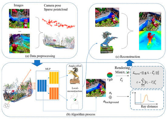
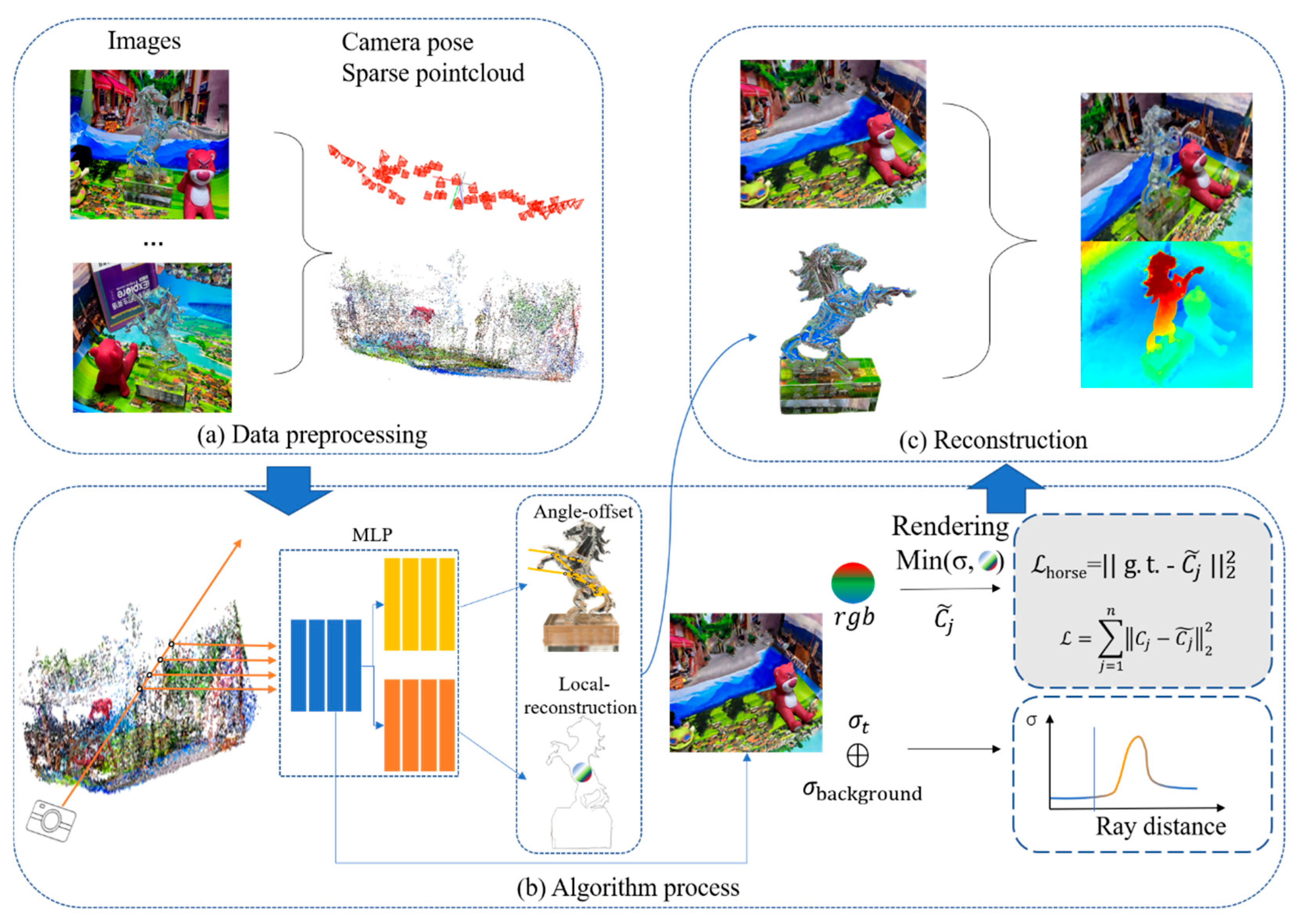
The overall framework of the proposed multi-cooperative neural radiance field method for reconstructing scenes containing transparent objects is illustrated in Figure 1. In this method, scenes containing transparent objects are divided into two parts: transparent regions and non-transparent regions. Since the reconstruction scene contains transparent objects, the process begins with scene preprocessing to separate transparent and non-transparent regions. The non-transparent areas are processed using standard methods, while the transparent regions are handled separately by introducing an angular offset network and local reconstruction network. These specialized networks model the internal and surface properties of transparent objects. Finally, all reconstruction results are integrated to form the complete scene. Figure 1a shows the sparse point cloud, as well as the camera poses and orientations extracted from the scene. In Figure 1b, rays are cast from the camera to sample the scene, and the sampled points are fed into a multi-cooperative neural radiance field modeled by a multilayer perceptron (MLP). The scene distinguishes between transparent and non-transparent regions for targeted reconstruction. The final reconstruction result is shown in Figure 1c.
Figure 1.
Overall method flowchart. (a) Data processing; (b) Algorithm processing; (c) Reconstruction.
2.2. Region Separation in Scenes Containing Transparent Objects
In this method, scenes containing transparent objects are divided into two parts: transparent regions and non-transparent regions. First, all areas in the scene are reconstructed in a preliminary 3D to obtain the initial point cloud data of the scene, and then an implicit neural radiance field network is introduced to predict reconstruct the implicit field for each sampling point in the scene. During reconstruction, the network continuously compares the predicted color values of sampled points with the corresponding ground truth colors in the original images and computes the reconstruction loss. Due to internal refraction and reflection within transparent objects, light rays deviate from straight-line paths, resulting in larger reconstruction loss, the regions with larger errors are typically identified as transparent objects, while those with smaller errors are classified as non-transparent.
While refractive effects often lead to larger photometric residuals, we clarify that transparent–non-transparent separation should not be interpreted as relying on the residual magnitude alone. In practice, we use the residual together with opacity evidence from the radiance field and multi-view consistency. Transparent regions tend to exhibit persistently higher residuals across views due to refractive ray deviation and lower or spatially varying volumetric density compared to opaque surfaces.
In contrast, low-texture opaque areas or shadowed regions can also produce residuals, but they are usually explainable by high density/opacity and are less consistent across viewpoints. Therefore, we recommend using a joint score that combines normalized photometric residuals with density/opacity cues (and optionally the variance of residuals across views) to reduce misclassification under challenging illumination. To further mitigate false positives in low-texture or shadowed areas, we apply robust weighting to the photometric term (e.g., downweighting pixels with extremely low gradients or very low intensity) so that ambiguous regions do not dominate the separation. This improves stability when illumination changes or cast shadows occur, where the raw residual may not reliably indicate transparency. That the separation is not intended to rely on the raw photometric error alone. Instead, we describe a more robust interpretation that combines photometric residual patterns across views and density evidence from the radiance field to avoid confusing low-texture/shadow regions with transparency. We also add a practical note on applying robust loss/weighting to downweight ambiguous pixels (e.g., extremely low-gradient or heavily shadowed regions), thereby reducing misclassification risk in challenging illumination.
The core parameters of the implicit field are the predicting color value C and the volumetric density
at each sampled point, the C represents the optical characteristics of the point, while the density
ecodes the geometric structure of the scene, the volumetric density
indicates the opacity of a spatial point, the probability that a light ray is occluded. High density values typically correspond to object surfaces, whereas low density values indicate transparent or empty regions.
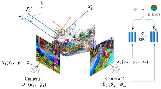
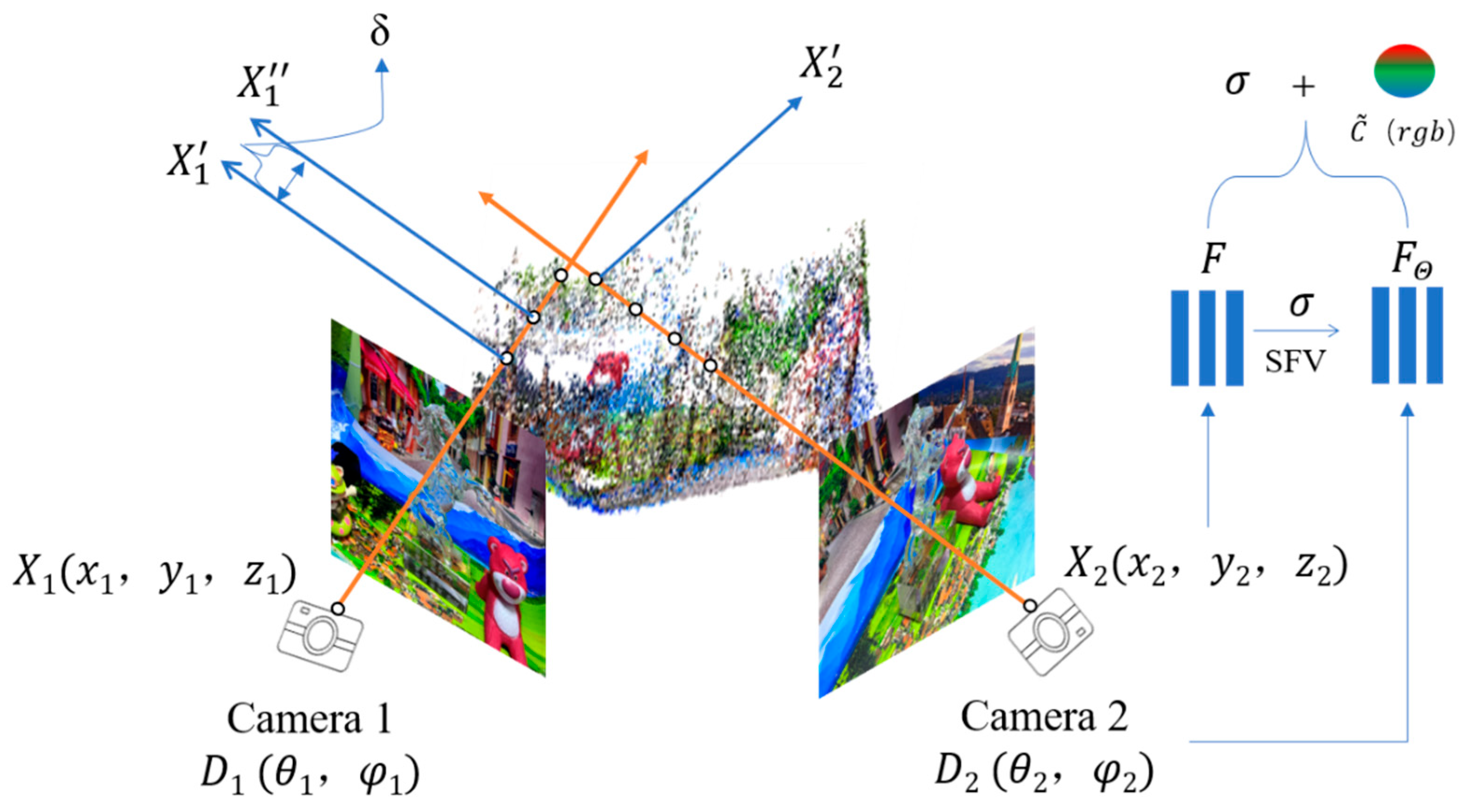
As shown in Figure 2, cameras positioned at different locations capture information from the same scene, the input to the implicit neural field is a five-dimensional function comprising the 3D spatial coordinates of the sampled point
and the viewing direction of the camera
, this input yields the volumetric density
and a 256-dimensional spatial feature vector for the sampled point, the spatial feature vector and the viewing direction
are fed into a directional multilayer perceptron
, which combines them with the density
, the network outputs the predicted color value for the sampled point, capturing view-dependent optical effects such as specular reflection and refraction. The computation of the color value is described in Equation (1).
where
is the distance between two adjacent sampled points along the ray, the
represents the
-th sampled point,
represents the ground truth color of the
-th sampled point,
is the transmittance from the ray origin to the
-th sampled point, representing the attenuation of light (i.e., the transparency) along the ray.
Figure 2.
Camera viewpoints and uniform ray sampling from multiple positions.
To compute the error between the predicted color
and the ground truth color
, we introduce a photometric loss function to be minimized, the squared difference is weighted by the volumetric density along the ray, the final loss is computed by averaging the photometric error over all sampled points.
where
is the number of rays are processed in each iteration,
represents the ground truth color of the
-th point,
is the predicted color value produced by the network,
is the Euclidean norm, which measures the difference between the predicted and ground truth values.
Due to refraction and reflection within transparent objects, light propagates along non-linear paths during imaging, this violates the straight-line propagation and sampling assumption made in implicit field-based models, thus the prediction error in transparent regions tends to be significantly higher. By computing the error between the predicted color values of sampled points and the corresponding ground truth color values in the original image using Equation (2), regions with large color discrepancies can be identified as transparent object areas, whereas regions with smaller errors are considered non-transparent.
2.2.1. Angular Offset Field for Refraction Rays
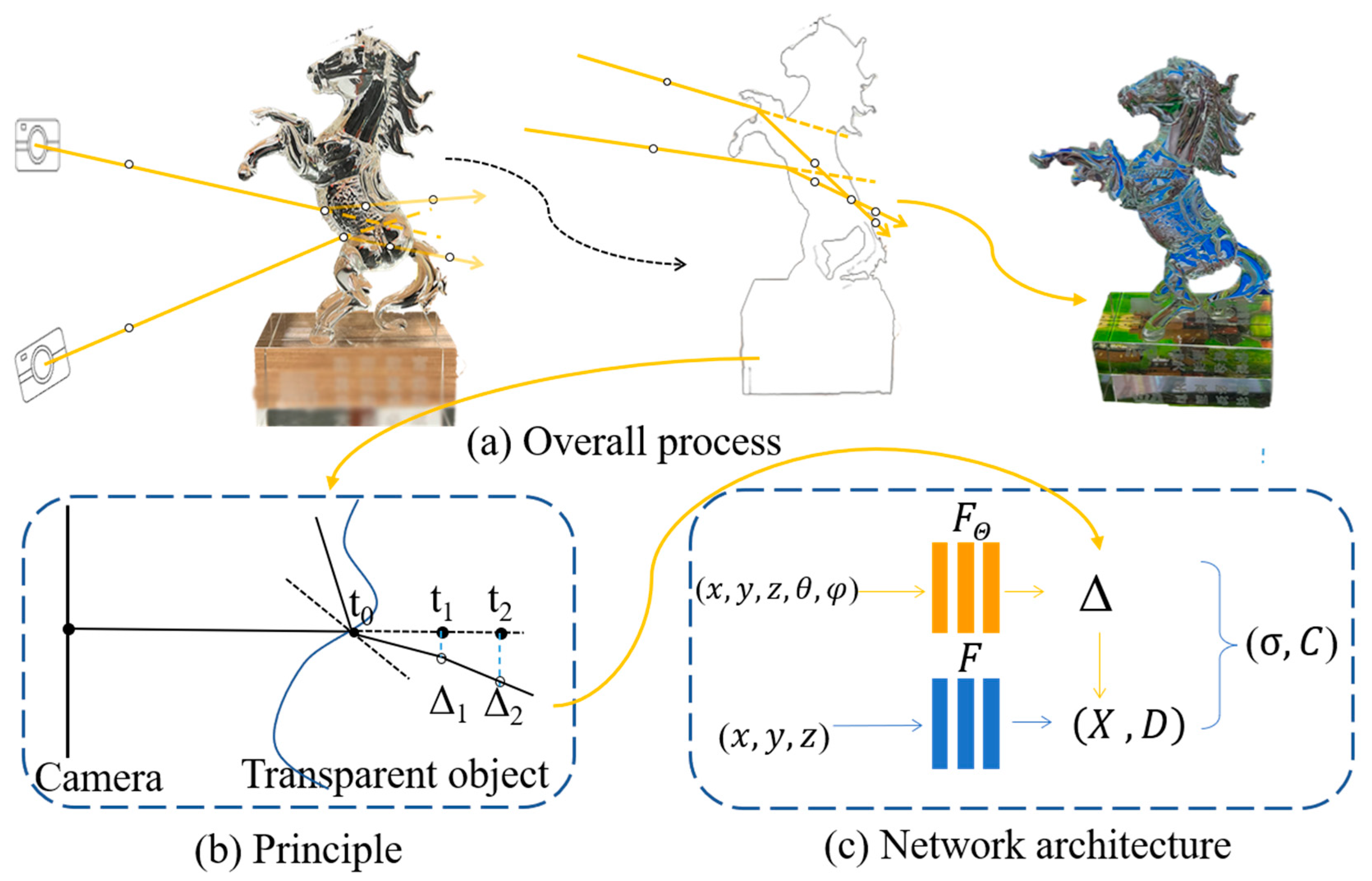
Given the significant impact of light refraction on 3D reconstruction of transparent objects, regions containing transparent materials require special treatment. Existing research on implicit neural fields typically assume that light travels in straight lines. However, in practice, light rays bend when passing through transparent materials, forming a refraction angle with respect to the original direction, it is necessary to account for refractive angular deviations within transparent objects during scene reconstruction, we introduce the angular offset field, which optimizes multiple angular deviations to better model the refractive behavior of light within transparent materials.
The core idea of the angular offset field is to simulate refractive angular deviations by adjusting the propagation paths of light rays. Based on varying viewpoints, the network is trained to optimize the refractive angles of rays within transparent objects, as illustrated in Figure 3. In Figure 3a, rays emitted from cameras at different viewpoints, indicated by yellow arrows deviate from straight-line paths as they pass through transparent objects. Therefore, the angular offset field introduces a deviation
to simulate the altered paths of light within transparent media. In Figure 3b, this angular adjustment enables the network to iteratively refine
, allowing accurate modeling of ray propagation inside transparent regions. Considering the internal material of the transparent object is non-uniform, a ray originating from point a experiences different angular deviations
and
at different positions, from t0 to t2. As the camera viewpoint changes, both the ray’s spatial origin
and the viewing direction
vary accordingly, the angular radiance field continuously adjusts
to ensure accurate modeling of refractive effects under different viewing angles.
Figure 3.
Specialized handling of transparent regions by the angular offset field. (a) Overall process; (b) Principle; (c) Network architecture.
The formation of angular deviations in ray simulation is modeled as a dynamic learning process. The network continuously adjusts and validates the offset based on changes in the camera’s viewing angle, ensuring that the final reconstruction accurately reflects the true characteristics of the transparent object. The angular offset radiance field
adopts a structure similar to that of a spatial multilayer perceptron, as shown in Figure 3c. Since view direction must be taken into account, the network requires the camera’s directional information as input. The angular offset field network dynamically computes the angular deviation
for each sampled point, as defined in Equation (3).
The computed angular deviation
and the 3D spatial coordinates
are used as inputs, as shown in Equation (4). The network then predicts the volumetric density σ and the corresponding color
, as defined in Equation (4).
where
represents the 3D spatial coordinates of each sampled point in the image, and
represents the camera’s viewing direction.
2.2.2. Local Reconstruction Field for Reflection
On the surface of transparent objects, strong illumination or specific viewing angles may result in total reflection, as illustrated by ray b in Figure 3b. During reconstruction, these reflected rays can obscure the underlying structure of the scene. To address the impact of reflection on ray paths, we propose a local reconstruction network module that performs secondary reconstruction specifically for reflective regions on transparent surfaces. The combination of the results of the local reconstruction network and those of the corner offset network can improve the reconstruction accuracy of the detailed features in the transparent area.
To estimate the reflection characteristics of each region, the natural reflection index
was used. As different materials exhibit varying reflective characteristics, the reflection index
varies across regions. The reflection index is related to the volumetric density
of the sampled points, as defined in Equation (5).
where
represent the volumetric density of the
-th sampled point and the distance between adjacent sampled points, respectively.
The local reconstruction field primarily targets the surfaces of transparent objects rather than their interiors. Consequently, under identical lighting conditions, the appearance of transparent surfaces varies with the viewing angle. Therefore, the local reconstruction network receives only the camera viewing direction as input, without the need for spatial coordinate information. The prediction output of the local reconstruction field for surface regions is modulated by a reflection parameter
The predicted color is obtained by multiplying the reflection parameter
with the ground truth color value. The reflection parameter
is derived from the reflection index
, as defined in Equation (6).
During processing, the local reconstruction field for transparent regions uses the ground truth values of the transparent surface as the reference. The predicted color value from the local reconstruction field is computed as shown in Equation (7).
where
represents final predicted color value from the local reconstruction field.
2.2.3. Multi-Cooperative Neural Radiance Field Combining Angular Offset and Local Reconstruction Fields
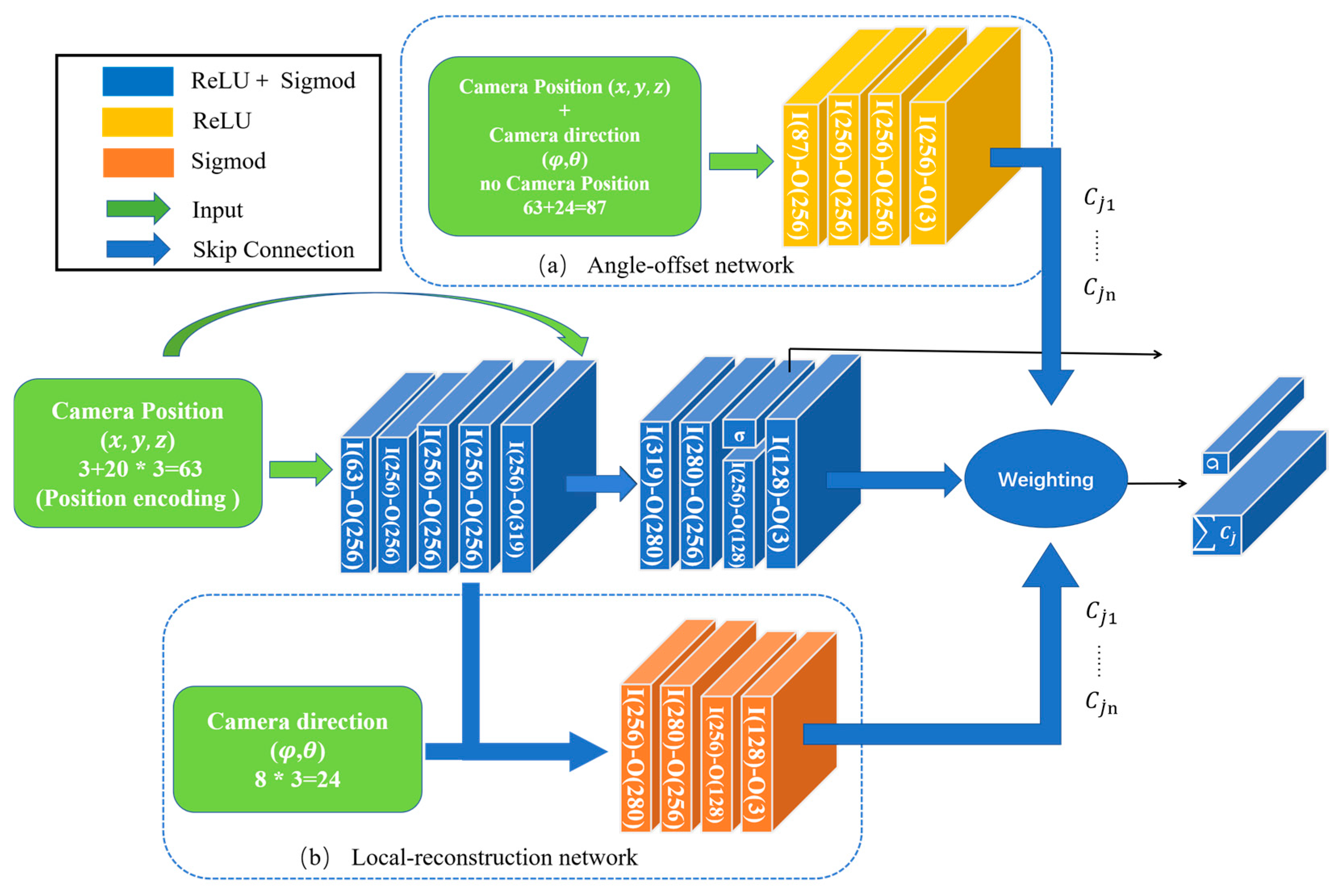
The proposed reconstruction framework integrates both the angular offset field and the local reconstruction field into a unified multi-cooperative neural radiance field. The overall network architecture is illustrated in
Figure 4. Figure 4a
shows the angular offset network, while Figure 4b
depicts the local reconstruction network for transparent regions. The input to the multilayer perceptron (MLP) consists of the 3D coordinates of the ray origin and the corresponding camera viewing direction. After passing through the angular offset network, the local reconstruction network, and the MLP, the model outputs the volumetric density
and the final predicted color value
.
Figure 4.
Overall network architecture for scene reconstruction. (a) Angle-offset network; (b) Local-reconstruction network.
The 3D position of the camera-emitted ray
is first processed through positional encoding before being fed into the MLP network. Within the network, the encoded position is initially passed into a spatial MLP network. We apply the ReLU and Sigmoid activation functions to stabilize feature distributions. The network first outputs the volumetric density
values for all sampled points. The camera viewing direction
is directly related to the final color prediction of each region. It is fed into both the angular offset network and the local reconstruction network for transparent regions to extract direction-aware features. The predicted color value
is then produced, corresponding to the output defined in Equation (2).
The angular offset network, shown in Figure 4a, takes both the camera position and viewing direction as input. It employs the ReLU activation function and outputs the predicted color values of transparent objects for each specific viewing angle. Figure 4b
illustrates the local reconstruction network for transparent regions. This network uses only the camera viewing direction as input and applies a Sigmoid activation function to perform secondary processing of the object surface. The sampled points from all regions are processed through the multi-cooperative neural radiance field network, producing separate color predictions. These color predictions are then aggregated using direct weighted summation to generate the final rendered image.
The proposed multi-cooperative neural radiance field is optimized with a special focus on detail recovery and the modeling of refraction and reflection effects in transparent objects. This leads to significant improvements in the overall reconstruction quality of scenes containing transparent objects, yielding results that closely match real-world appearances. All network modules are carefully designed to account for the diverse and complex light behaviors present in such scenes. This ensures the robustness and general applicability of the proposed method.
2.3. Reconstruction Result Integration
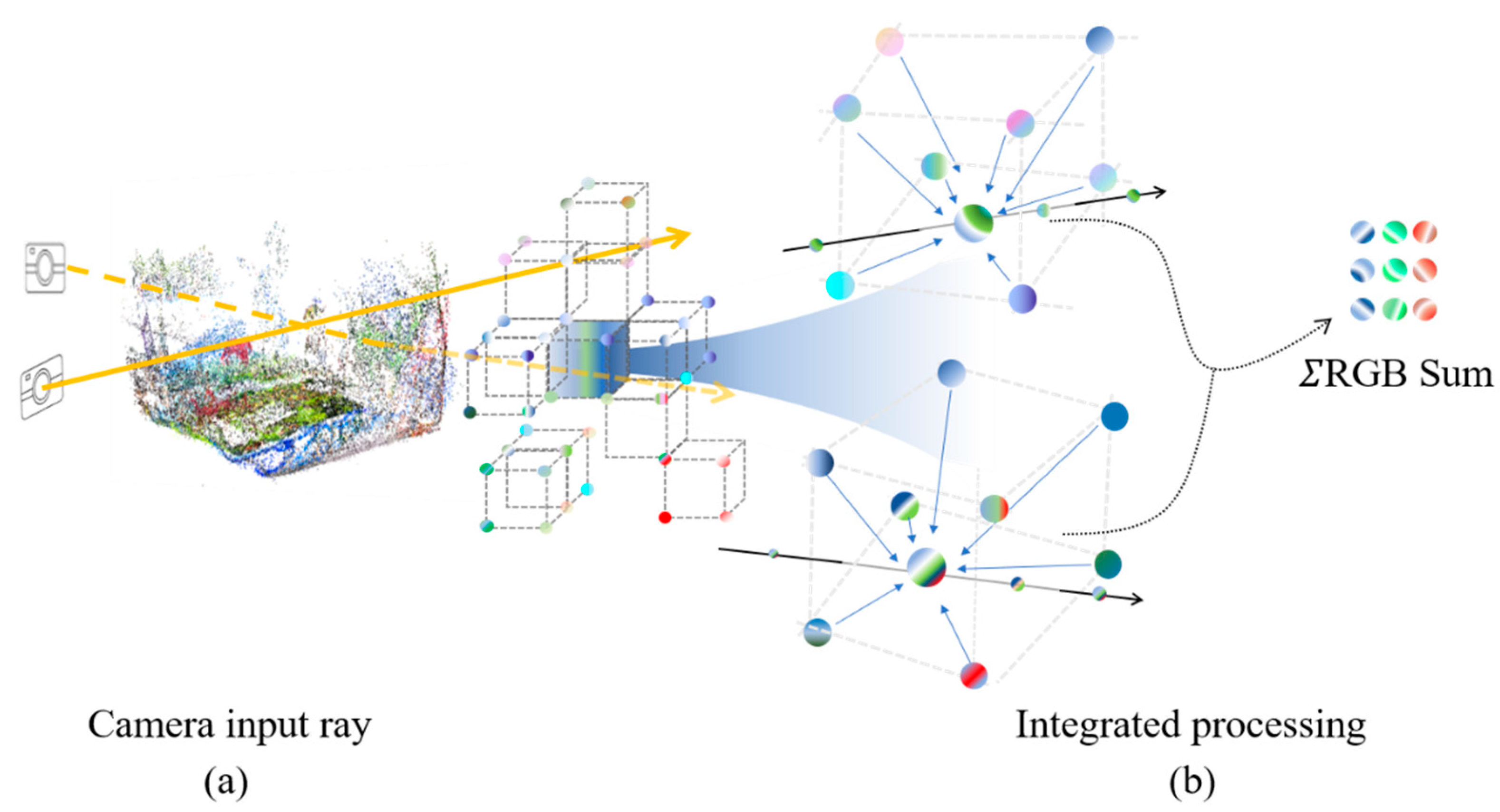
The transparent regions of the scene are specially processed using a multi-cooperative neural radiance field composed of an angular offset field and a local reconstruction field. These results are integrated with the reconstruction of the non-transparent regions to produce the final complete reconstruction. The process of integrating reconstruction results is illustrated in
Figure 5. Figure 5a
shows rays emitted from cameras at different viewpoints traversing the scene’s spatial point cloud, where uniform sampling and point-wise processing are performed in both transparent and non-transparent regions. in Figure 5b, all sampled points along each ray are processed through the angular offset field, the local reconstruction network, and the MLP network. The predicted color values
(r, g, b) are computed through cumulative integration. Finally, the predicted color values
are aggregated via a weighted summation approach, ensuring that the integrated output best approximates the true color appearance of the scene.
Figure 5.
Scene partitioning and integration of predicted color values. (a) Camera input ray; (b) Integrated processing.
To address occlusion issues that arise during the reconstruction process, we introduce the weight factor
to evaluate the contribution of each sampled point. The volumetric density of each sampled point along a ray is used to determine its relative importance and the transparency level of the corresponding region. This relationship is formally defined in Equation (8).
where a larger
indicates a greater contribution of the sampled point to the final rendered image. By aggregating the weights of all sampled points along the ray, the total contribution of the ray can be computed as a smaller weight implies a lower contribution. This process enables the generation of a more accurate reconstruction result.
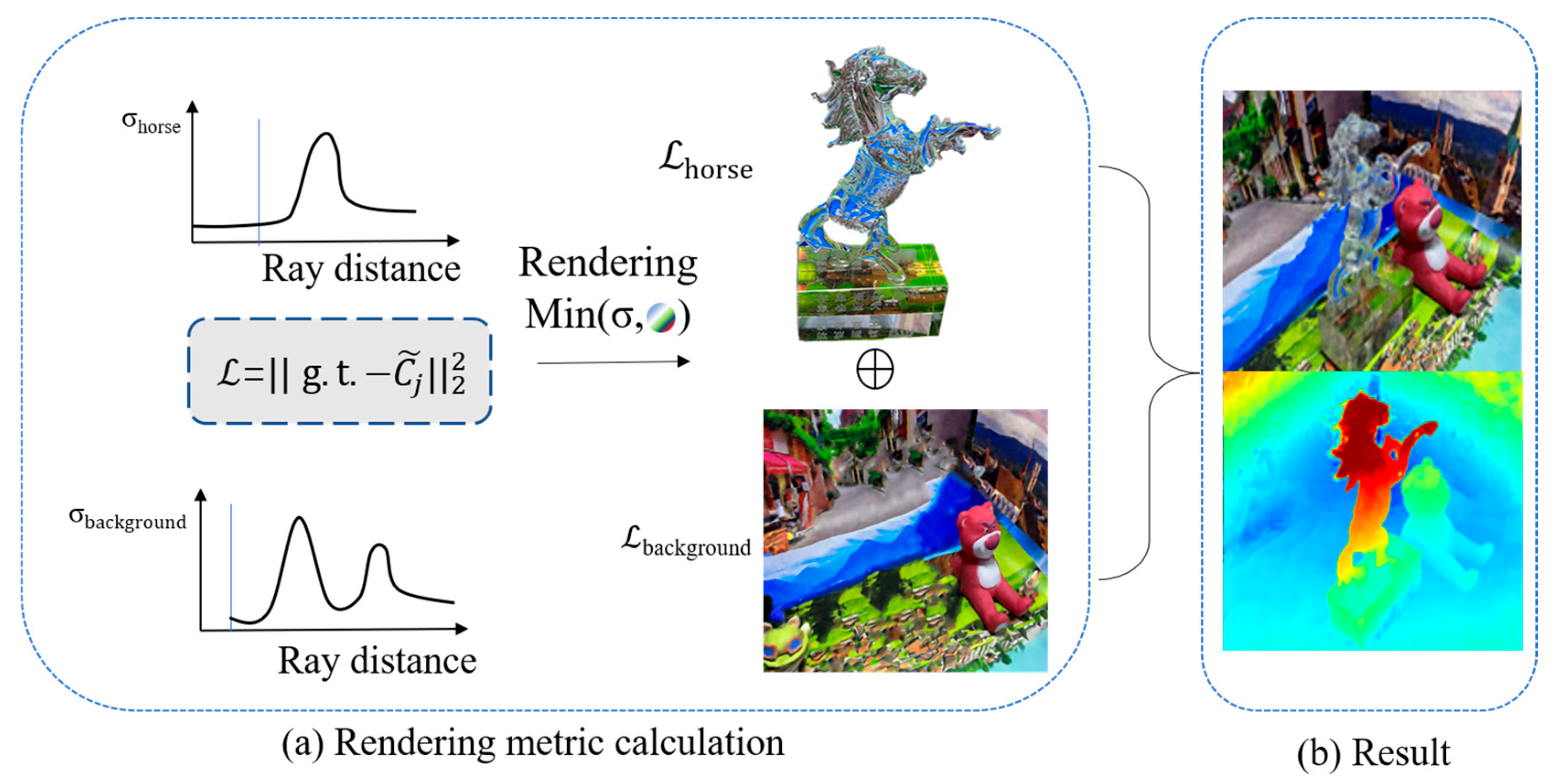
During scene reconstruction, the loss values across all regions are continuously computed and compared with images from the validation set. As shown in Figure 6a, the loss computation is based on the volumetric density of sampled points within the scene. The scene is divided into transparent and non-transparent regions, and photometric loss is minimized separately for each region before integrating the results into the final reconstruction.
Figure 6.
Loss processing for transparent and non-transparent regions. (a) Rendering metric calculation; (b) Result.
The angular offset field is an effective ray-deviation proxy learned from multi-view photometric supervision, rather than an explicit enforcement of Snell’s law. The learned offset remains physically meaningful under common assumptions in refractive scene reconstruction: static scenes, piecewise-smooth transparent surfaces, moderate refraction without severe dispersion, and approximately homogeneous (or slowly varying) refractive index within a transparent object. Under these conditions, the offset can approximate the net deviation introduced near refractive interfaces and helps the radiance field explain view-dependent distortions that cannot be modeled by straight rays.
As illustrated in Figure 6b, the predicted color values are produced by the neural radiance field network after separately reconstructing the transparent and non-transparent regions of the scene. The output includes multi-view synthesized images for validation as well as the corresponding depth maps. The final 3D reconstruction of the transparent-object-containing scene more accurately reflects the lighting conditions and transparency characteristics of the real environment.
2.4. Scope of Reflection Modeling and Limitations
The local reconstruction field is designed to capture view-dependent surface appearance changes (e.g., reflection highlights) by conditioning on the viewing direction and surface-proximity cues implied by density. Mixed refraction–reflection and partial transparency can be approximated through the view-dependent radiance and volumetric compositing. Nevertheless, the formulation is not a full physically based surface model: highly specular multi-bounce reflections, strong environment-map reflections, or rough glossy microfacet effects may not be fully captured, which can lead to residual artifacts in highly specular environments.
3. Experiments
3.1. Data Acquisition and Preprocessing
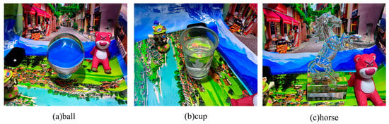
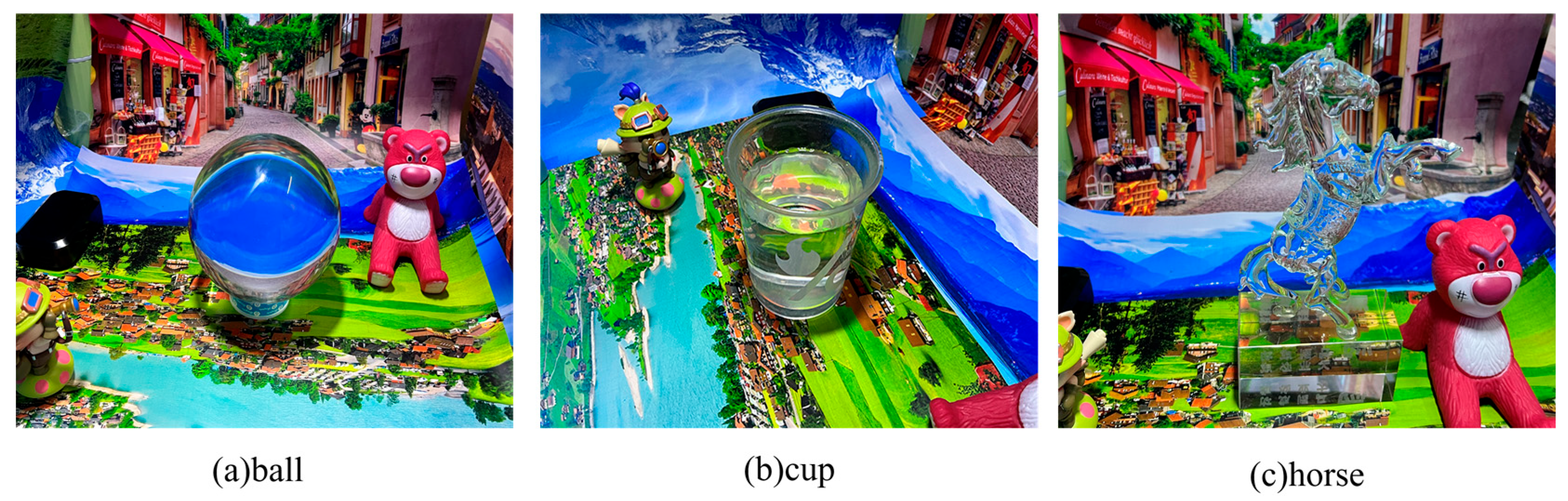
To evaluate the proposed method, we constructed a dedicated dataset specifically designed for scenes containing transparent objects. The dataset includes various transparent objects, ranging from simple geometric glass balls to horses with complex engraved textures.
Figure 7
shows sample images from different viewpoints. In order to capture the internal optical behavior of transparent objects, high-precision images were collected from multiple perspectives under different lighting conditions. On average, 80 high-resolution images (4032 × 3024 pixels) were captured in each scene. This ensures that key optical phenomena, such as mirror highlights, reflection, and refraction, are fully captured on each transparent object. (a) Scenes with transparent balls; (b) scene and cup after cup; (c) a transparent horse sculpture scene with complex textures.
Figure 7.
Dataset of scenes containing transparent objects. (a) ball; (b) cup; (c) horse.
Real-world scene images captured by mobile devices are often affected by ambient lighting conditions, which can degrade reconstruction accuracy. To mitigate this, we adjusted brightness, contrast, and color saturation parameters during the image acquisition process. These adjustments effectively reduced the impact of lighting interference on feature recognition, enhancing the network’s robustness and performance under complex illumination conditions.
We apply a series of preprocessing steps to the images in the dataset. Camera parameters were estimated, and feature point matching was performed to obtain a sparse point cloud. Shell commands were used to configure input parameters, ensuring the image resolution ratio fed into the network was maintained at 672:504. The dataset was split into training and validation sets, and both qualitative and quantitative results were reported on the test images.
3.2. Experimental Environment and Training Strategy
The relevant hardware, software, and training configurations used in this study are summarized in Table 1. The proposed multi-cooperative neural radiance field framework was developed using Python 3.8. Several Python libraries were employed in the implementation, including PyTorch, OpenCV, and NumPy. The initial learning rate was set to 0.0005 and optimized using the Adam optimizer with exponential decay. The batch size was set to 40. During the initial phase of training, the network employed an exponential learning rate decay by default. In addition, the framework supports linear and step decay strategies, which can be specified via command-line arguments to override the default strategy. A dynamic learning rate adjustment mechanism was also integrated into the training process. When the validation loss fails to improve over several epochs, the learning rate is automatically reduced to enhance the stability and convergence of the training process.
Table 1.
Hardware, software, and training parameters used in the experiments.
3.3. Evaluation Metrics
To comprehensively evaluate the performance of the proposed method, the following metric was used:
SSIM (Structural similarity index): Measures the similarity between two images in terms of luminance, contrast, and structural information. The SSIM value ranges from 0 to 1. A score closer to 1 indicates higher structural similarity and better reconstruction quality.
where
and
represent the mean luminance of images
and
, respectively.
and
are the standard deviations of
and
,
is the covariance between images
and
,
are constants introduced to stabilize the SSIM calculation, particularly when the denominators are small.
LPIPS (learned perceptual image patch similarity): The deep learning-based metric for assessing perceptual image quality. It predicts the perceived similarity between images using a trained neural network. A lower LPIPS value indicates smaller perceptual differences, making it particularly effective for evaluating image quality from a human visual perspective.
where
and
represent the two images being compared,
and
are the features extracted from the l-th layer of a deep neural network for images
and
, respectively.
represents the weight assigned to each layer, and
is the squared Euclidean distance at that layer, representing the difference between the two images at the feature level.
MSE (Mean squared error): The fundamental metric used to measure the reconstruction error, quantifying the difference between the model’s output and the ground truth.
PSNR (Peak signal-to-noise ratio): Measures the difference between a reconstructed image and the original image. A higher PSNR value indicates better reconstruction quality. As a widely used image quality metric, it is derived from the Mean Squared Error (MSE) and reflects the image’s sharpness and the accuracy of detail restoration.
where
reprensents the maximum pixel value of the image and MSE refers to the Mean Squared Error.
3.4. Comparative Experiments
Our experiments are conducted on real-captured multi-view images. Camera intrinsics and extrinsics are estimated using COLMAP. The proposed method is trained without any ground-truth 3D geometry; supervision is provided by RGB images and camera parameters via image-based rendering losses. Since the learned representation is an implicit radiance density field, we present reconstruction results mainly as novel-view renderings.
To validate the effectiveness of the proposed method, we conducted comparative experiments with several existing implicit radiance field approaches. The purpose of these comparisons is to assess the advantages of our approach in handling optical phenomena such as refraction and reflection in transparent objects. In particular, we focus on its ability to recover fine details in specular and reflective regions. NeRF, serving as the baseline method, introduced the concept of using implicit radiance fields for object and scene reconstruction. NeRFReN was specifically optimized for handling specular highlights and reflections, making it well-suited for scenes containing reflective materials. LB-NeRF integrates light field techniques and enhances performance by learning from multi-view images. It demonstrates notable improvements in capturing optical effects and is particularly effective in modeling illumination and refraction under varying viewpoints. TensoRF leverages tensor decomposition techniques to strike a balance between computational efficiency and high-fidelity scene modeling.
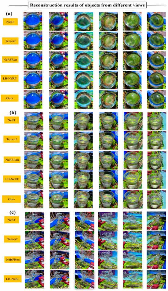
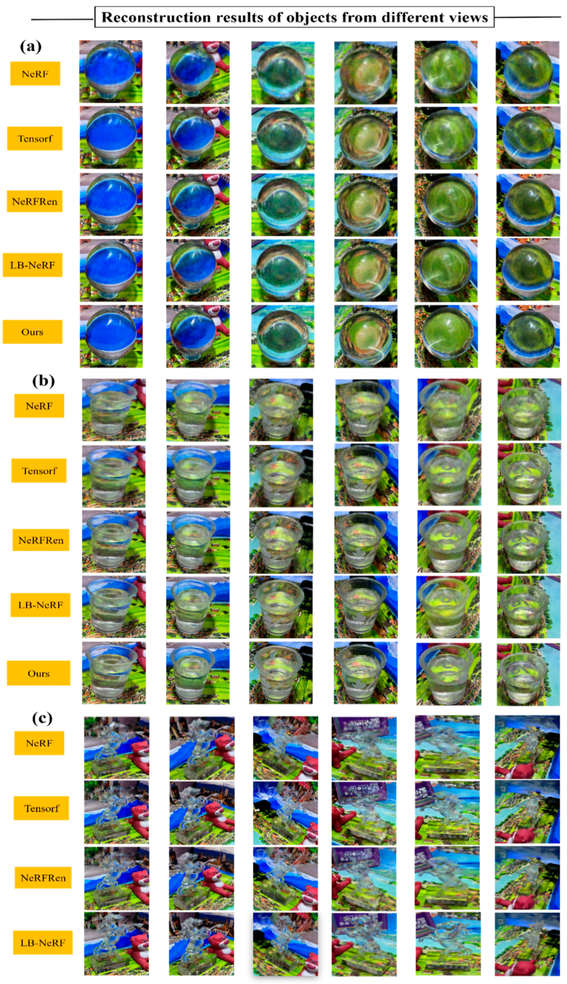
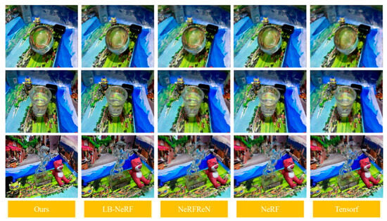
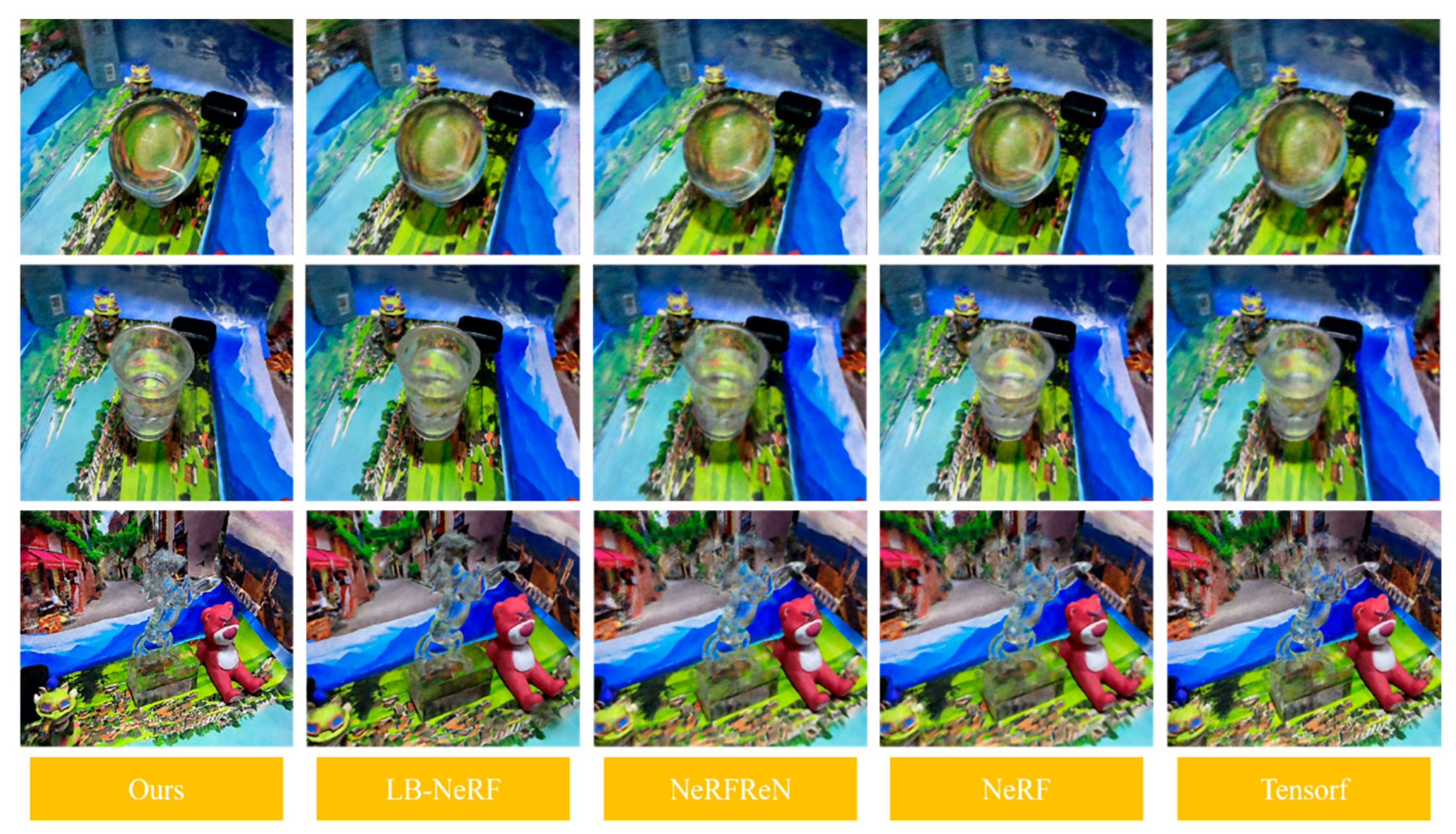
Figure 8
presents validation results from our proposed dataset, showcasing different transparent objects viewed from multiple angles.
Figure 8.
Partial multi-view reconstruction results of different transparent objects in the scene. (a) ball; (b) cup; (c) horse.
Figure 8a shows a transparent ball, Figure 8b shows a glass cup, and Figure 8c shows a transparent horse sculpture with intricate surface details. The multi-cooperative neural radiance field enables effective multi-view reconstruction of these transparent objects, successfully capturing both scene content and surface characteristics from various perspectives. The left column shows the different methods in the experiment. The right side shows the reconstruction (column) results from different perspectives using different methods (rows).
The reconstruction results in complex transparent-object scenes reveal that some methods fail to handle light refraction and reflection properly, resulting in blurred and distorted outputs. Although certain methods achieve moderate improvements, they still struggle with reconstructing fine details and object boundaries. In contrast, our proposed method can reconstruct the detailed structure and shape of transparent objects more faithfully, capturing their optical characteristics to a greater extent.
Figure 9
presents selected validation views from the visual reconstruction results of scenes containing transparent objects.
Figure 9.
Visualization of scene reconstruction from selected viewpoints.
Under our custom dataset, the reconstructed results show a clear improvement over other methods in terms of overall scene fidelity. Our method achieves a more complete reconstruction of the contours of transparent objects in the scene, while also preserving the structural integrity of other non-transparent regions without noticeable distortion.
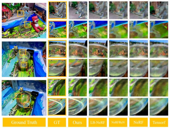
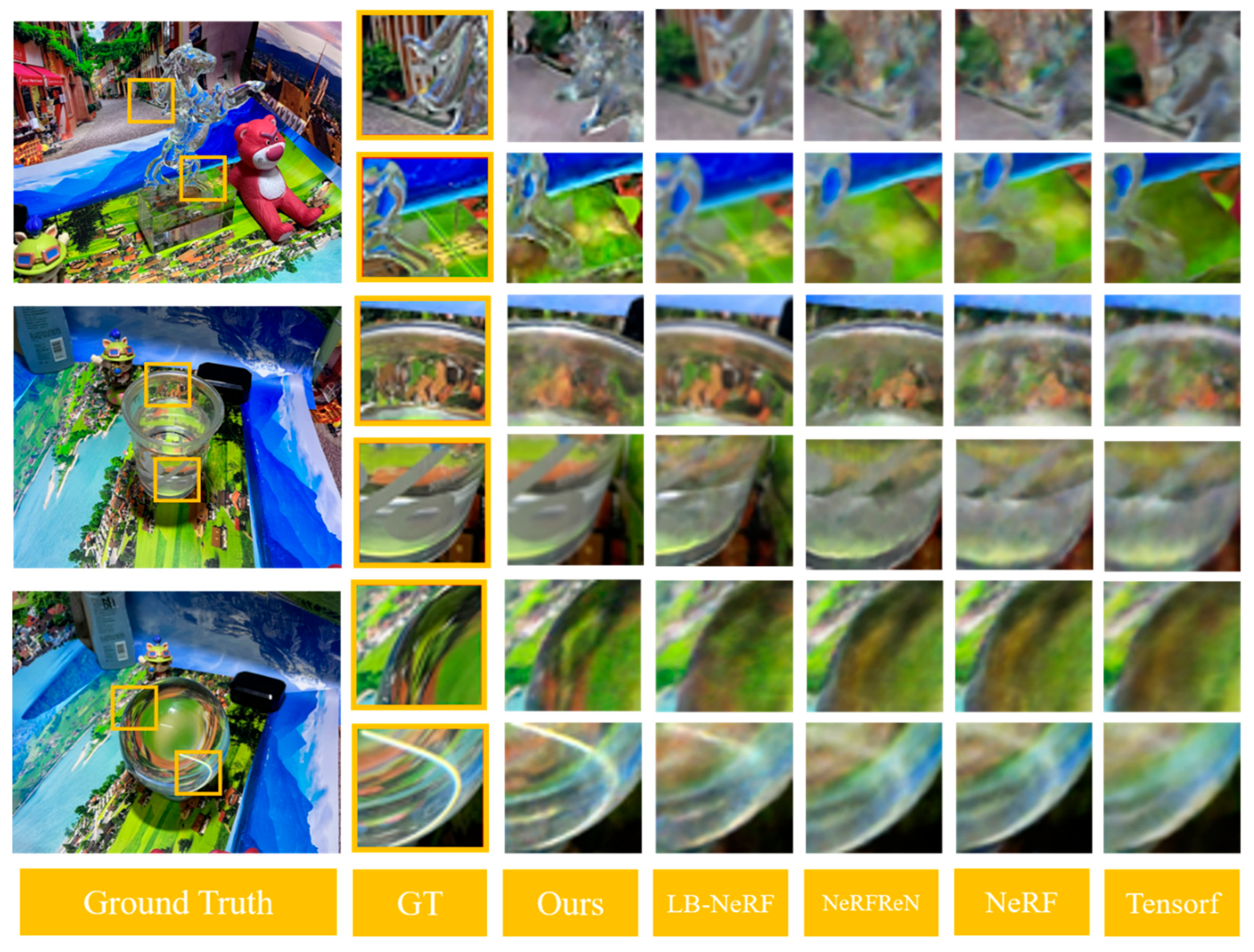
Figure 10
shows detailed reconstruction results, focusing on the local reconstruction of transparent objects in the scene.
Figure 10.
Detailed reconstruction results of transparent objects in the scene.
Compared to the original images, our method effectively restores fine details of the transparent objects in specific regions and preserves their original glossiness from certain viewpoints.
Table 2
presents a performance comparison of various methods on our dataset.
Table 2.
Comparison of metrics for different methods on our real dataset.
Specifically, our approach achieves improvements of at least 0.8 in PSNR and 0.2 in SSIM, while reducing LPIPS and MSE by at least 0.02 and 0.03, respectively, compared to other methods.
To evaluate the effectiveness of the proposed method, we conducted a series of comparative experiments on different datasets containing scenes of transparent objects. As shown in Table 3, the television and mirror are reflective scenes, which are from the rffr [22] mirror surface dataset, while the transparent object data, including transparent spheres and glass objects, are from the Eikonal dataset. The experimental results are shown in Table 3. It can be known from the data in the table that our method is superior to other methods.
Table 3.
Comparison of metrics for different methods on the other dataset.
3.5. Module Experiment
To validate the effectiveness of the proposed angular offset field (Angle-offset) and local reconstruction field (Local-reconstruction) modules in our transparent object 3D reconstruction method, we remove each module from the model and observing performance changes and clearly assess the contribution of each component to the final reconstruction quality.
The results in
Table 4
demonstrate the effectiveness of the proposed modules based on experiments conducted on the dataset introduced in this paper. We kept the hyperparameters constant in the experiment, maintaining the values from the initial experiment.
Both the angular offset field and local reconstruction field modules improve performance compared to the baseline method. Specifically, adding these modules increased PSNR and SSIM by 1.5 and 0.7, respectively, while reducing LPIPS and MSE by 0.06 and 0.07. Moreover, the combined use of both modules yields better results than when either module is applied individually.
Table 4.
Impact of different modules on reconstruction metrics.
3.6. Computational Complexity
Our approach extends a standard NeRF-style backbone with two lightweight branches: an angular offset field for effective ray deviation modeling and a local reconstruction field for view-dependent surface appearance refinement. Because these branches are evaluated on the same sampled points along rays, the additional training cost is approximately linear in the extra branch forward passes, while the ray sampling and volumetric rendering pipeline remain unchanged.
4. Discussion
4.1. Limitations and Failure Cases
Our current method assumes static scenes and primarily targets controlled captures where the number of interacting transparent objects is limited. Performance may degrade in unconstrained real-world scenes with multiple interacting transparent objects (multi-refraction and inter-reflection), unknown or dynamic lighting, dynamic backgrounds, strong caustics, and highly specular surroundings. These cases introduce complex light transport that is difficult to explain with a single learned offset field and local appearance compensation, and they motivate future extensions such as explicit illumination modeling, interaction-aware multi-object reasoning, or dynamic-scene formulations. In addition, although our custom dataset includes objects with different shapes and surface details (e.g., balls, cups, and a textured horse sculpture), it does not cover the full diversity of real-world transparent materials (e.g., strong tint, rough glass, multi-layered plastics) and extreme geometries. Therefore, extrapolation to a broader range of transparent objects should be interpreted with caution. We also note that errors in transparent-region separation can affect which branch dominates optimization; our sensitivity analysis in
Section 3.5
discusses how such errors influence reconstruction quality, and suggests robust weighting and multi-view consistency cues as mitigation.
4.2. Parameter, Memory, and Convergence Stability
Our method extends a standard NeRF-style backbone with two lightweight branches (angular offset and local reconstruction). Parameter growth is modest, because both branches are shallow MLPs and reuse the same positional/view encodings as the backbone. In practice, the overall parameter increase is small compared with the backbone and does not change the model’s training/inference regime. GPU memory and runtime are still dominated by volumetric rendering, i.e., the number of rays processed per iteration and the number of samples evaluated along each ray.
Convergence stability can be more difficult in refractive and specular regions because the offset and view-dependent terms may produce large gradients early in training. We found the following implementation details useful:
Bounded predictions: constrain angular offsets and reflection-related weights with bounded activations
as
sigmoid and keep RGB outputs in a valid range. Use non-negative density activations to avoid unstable transmittance.
Warm-up and differential learning rates: first, stabilize the backbone; then, progressively enable/weight the two branches; optionally use a smaller learning rate for the offset branch. Gradient clipping is also effective for preventing spikes.
5. Conclusions
This paper proposes a multi-cooperative neural radiance field approach for scenes containing transparent objects, achieving high-fidelity reconstruction of both the overall scene and fine details of transparent materials. The method maps 3D spatial points and view directions into color
and density
using a basic implicit neural radiance field formulation. To address the limitations of neural radiance fields in accurately modeling refraction and reflection, this paper introduces an angular offset field to model the directional deviations of light within transparent objects, and the local reconstruction field is employed for secondary reconstruction of reflective surface regions. Experimental results demonstrate that the proposed method significantly improves reconstruction accuracy and generalization performance in containing complex transparent scenes. Compared with traditional methods, it more accurately captures the optical properties of transparent materials and generates high-quality 3D reconstructions. Future work could explore combining explicit geometry with the current multi-cooperative neural radiance fields to improve structural stability and editability. Integrating techniques, such as neural point cloud fusion or mesh-guided regional reconstruction, may also reduce training costs and accelerate the reconstruction process, while enabling transparent object contour extraction.
Author Contributions
Conceptualization, X.S. (Xiaopeng Sha); methodology, X.S. (Xiaopeng Sha) and W.S.; writing—original draft preparation, X.S. (Xiaopeng Sha) and W.S.; writing—review and editing, X.S. (Xiaopeng Sha), W.S., K.S., X.S. (Xinqi Sang), and S.W.; funding acquisition, X.S. (Xiaopeng Sha). All authors have read and agreed to the published version of the manuscript.
Funding
This research was supported by the Natural Science Foundation of Hebei Province (No. F2024501044), the Central Funds for Guiding Local Science and Technology Development in Hebei Province (No. 246Z2002G), and the Fundamental Research Funds for the Central Universities (No. 2025GFZD002) to Xiaopeng Sha.
Data Availability Statement
The original contributions presented in this study are included in the article. Further inquiries can be directed to the corresponding author.
Conflicts of Interest
The authors declare no conflicts of interest.
References
- Wang, Y.; Sun, X.; Jia, J.; Jin, Z.; Ma, Y. High-precision 3D teeth reconstruction based on five-view intra-oral photos. Displays 2025, 87, 10298. [Google Scholar] [CrossRef] [Scilit]
- Lin, N.; Gagnon, M.; Wu, K.Y. The third dimension of eye care: A comprehensive review of 3D printing in ophthalmology. Hardware 2024, 2, 1–32. [Google Scholar] [CrossRef] [Scilit]
- Ciliberti, F.K.; Guerrini, L.; Gunnarsson, A.E.; Recenti, M.; Jacob, D.; Cangiano, V.; Aubonnet, R. CT- and MRI-based 3D reconstruction of knee joint to assess cartilage and bone. Diagnostics 2022, 12, 279. [Google Scholar] [CrossRef] [Scilit] [PubMed]
- He, K.; Sui, C.; Huang, T.; Dai, R.; Lyu, C.; Liu, Y.H. 3D surface reconstruction of transparent objects using laser scanning with a four-layers refinement process. Opt. Express 2022, 30, 8571–8591. [Google Scholar] [CrossRef] [Scilit]
- Cao, J.; Cui, J.; Schwertfeger, S. GlassGaussian: Extending 3D Gaussian splatting for realistic imperfections and glass materials. IEEE Access 2025, 13, 31517–31531. [Google Scholar] [CrossRef] [Scilit]
- Pietroni, E.; Ferdani, D. Virtual restoration and virtual reconstruction in cultural heritage: Terminology, methodologies, visual representation techniques and cognitive models. Information 2021, 12, 167. [Google Scholar] [CrossRef] [Scilit]
- Chen, C.; Wang, H.; Zhang, Z.; Gao, F. Three-dimensional reconstruction from a fringe projection system through a planar transparent medium. Opt. Express 2022, 30, 34824–34834. [Google Scholar] [CrossRef] [Scilit]
- Lyu, J.; Wu, B.; Lischinski, D.; Cohen-Or, D.; Huang, H. Differentiable refraction-tracing for mesh reconstruction of transparent objects. ACM Trans. Graph. 2020, 39, 195. [Google Scholar] [CrossRef] [Scilit]
- He, K.; Sui, C.; Huang, T.; Dai, R.; Lyu, C.; Liu, Y.H. 3D surface reconstruction of transparent objects using laser scanning with LTFtF method. Opt. Lasers Eng. 2022, 148, 106774. [Google Scholar] [CrossRef] [Scilit]
- Liu, X.; Rego, J.D.; Jayasuriya, S.; Koppal, S.J. Event-based dual photography for transparent scene reconstruction. Opt. Lett. 2023, 48, 1304–1307. [Google Scholar] [CrossRef] [Scilit]
- Watanabe, A.; Miyazaki, D. Surface normal estimation of thin transparent objects from polarization of transmitted light. In Proceedings of the IEEE 5th International Conference on Multimedia Information Processing and Retrieval (MIPR), Online, 2–4 August 2022; pp. 1–8. [Google Scholar]
- Qian, Y.; Gong, M.; Yang, Y.H. 3D reconstruction of transparent objects with position-normal consistency. In Proceedings of the IEEE Conference on Computer Vision and Pattern Recognition (CVPR), Las Vegas, NV, USA, 27–30 June 2016; pp. 4363–4371. [Google Scholar]
- Chen, G.; Han, K.; Wong, K.-Y.K. TOM-Net: Learning transparent object matting from a single image. In Proceedings of the IEEE Conference on Computer Vision and Pattern Recognition (CVPR), Salt Lake City, UT, USA, 18–22 June 2018; pp. 9233–9241. [Google Scholar]
- Tong, Y.; Chen, H.; Yang, N.; Menhas, M.I.; Ahmad, B. 3D-CDRNet: Retrieval-based dense point cloud reconstruction from a single image under complex background. Displays 2023, 78, 102438. [Google Scholar] [CrossRef] [Scilit]
- Li, Z.; Yeh, Y.-Y.; Chandraker, M. Through the looking glass: Neural 3D reconstruction of transparent shapes. In Proceedings of the IEEE/CVF Conference on Computer Vision and Pattern Recognition (CVPR), Seattle, WA, USA, 13–19 June 2020; pp. 1262–1271. [Google Scholar]
- Shao, M.; Xia, C.; Duan, D.; Wang, X. Polarimetric inverse rendering for transparent shapes reconstruction. IEEE Trans. Multimed. 2024, 26, 7801–7811. [Google Scholar] [CrossRef] [Scilit]
- Xu, J.; Zhu, Z.; Bao, H.; Xu, W. Hybrid mesh-neural representation for 3D transparent object reconstruction. Comput. Vis. Media 2025, 11, 123–140. [Google Scholar] [CrossRef] [Scilit]
- Wang, J.; Liu, G.; Ding, W.; Li, Y.; Song, W. From visual understanding to 6D pose reconstruction: A cutting-edge review of deep learning-based object pose estimation. Displays 2025, 89, 103069. [Google Scholar] [CrossRef] [Scilit]
- Sha, X.; Si, X.; Zhu, Y.; Wang, S.; Zhao, Y. Automatic three-dimensional reconstruction of transparent objects with multiple optimization strategies under limited constraints. Image Vis. Comput. 2025, 160, 105580. [Google Scholar] [CrossRef] [Scilit]
- Mildenhall, B.; Srinivasan, P.P.; Tancik, M.; Barron, J.T.; Ramamoorthi, R.; Ng, R. NeRF: Representing scenes as neural radiance fields for view synthesis. Commun. ACM 2021, 65, 99–106. [Google Scholar] [CrossRef] [Scilit]
- Pumarola, A.; Corona, E.; Pons-Moll, G.; Moreno-Noguer, F. D-NeRF: Neural radiance fields for dynamic scenes. In Proceedings of the IEEE/CVF Conference on Computer Vision and Pattern Recognition (CVPR), Online, 19–25 June 2021; pp. 10318–10327. [Google Scholar]
- Guo, Y.C.; Kang, D.; Bao, L.; He, Y.; Zhang, S.H. NeRFReN: Neural radiance fields with reflections. In Proceedings of the IEEE/CVF Conference on Computer Vision and Pattern Recognition (CVPR), New Orleans, LA, USA, 19–24 June 2022; pp. 18409–18418. [Google Scholar]
- Fujitomi, T.; Sakurada, K.; Hamaguchi, R.; Shishido, H.; Onishi, M.; Kameda, Y. LB-NeRF: Light bending neural radiance fields for transparent medium. In Proceedings of the IEEE International Conference on Image Processing (ICIP), Bordeaux, France, 16–19 October 2022; pp. 3366–3370. [Google Scholar]
- Zhan, Y.; Nobuhara, S.; Nishino, K.; Zheng, Y. NeRFraC: Neural radiance fields through refractive surfaces. In Proceedings of the IEEE/CVF International Conference on Computer Vision (ICCV), Paris, France, 2–6 October 2023; pp. 17996–18005. [Google Scholar]
- Rawat, M.; Kanojia, D. Automated evidence collection for fake news detection. arXiv 2021, arXiv:2112.06507. [Google Scholar] [CrossRef] [Scilit]
- Bemana, M.; Myszkowski, K.; Revall Frisvad, J.; Seidel, H.P.; Ritschel, T. Eikonal fields for refractive novel-view synthesis. In Proceedings of the SIGGRAPH '22: Special Interest Group on Computer Graphics and Interactive Techniques Conference, Vancouver, BC, Canada, 7–11 August 2022; pp. 1–11. [Google Scholar]
- Barron, J.T.; Mildenhall, B.; Verbin, D.; Srinivasan, P.P.; Hedman, P. Mip-nerf 360: Unbounded anti-aliased neural radiance fields. In Proceedings of the IEEE/CVF Conference on Computer Vision and Pattern Recognition, New Orleans, LA, USA, 21–24 June 2022; pp. 5470–5479. [Google Scholar]
- Verbin, D.; Hedman, P.; Mildenhall, B.; Zickler, T.; Barron, J.T.; Srinivasan, P.P. Ref-nerf: Structured view-dependent appearance for neural radiance fields. In Proceedings of the 2022 IEEE/CVF Conference on Computer Vision and Pattern Recognition (CVPR), NewOrleans, LA, USA, 18–24 June 2022; pp. 5481–5490. [Google Scholar]
- Mildenhall, B.; Hedman, P.; Martin-Brualla, R.; Srinivasan, P.P.; Barron, J.T. Nerf in the dark: High dynamic range view synthesis from noisy raw images. In Proceedings of the IEEE/CVF Conference on Computer Vision and Pattern Recognition, New Orleans, LA, USA, 21–24 June 2022; pp. 16190–16199. [Google Scholar]
- Zhang, J.; Zhang, Y.; Fu, H.; Zhou, X.; Cai, B.; Huang, J.; Jia, R.; Zhao, B.; Tang, X. Ray priors through reprojection: Improving neural radiance fields for novel view extrapolation. In Proceedings of the IEEE/CVF Conference on Computer Vision and Pattern Recognition, New Orleans, LA, USA, 21–24 June 2022; pp. 18376–18386. [Google Scholar]
- Garbin, S.J.; Kowalski, M.; Johnson, M.; Shotton, J.; Valentin, J. Fastnerf: High-fidelity neural rendering at 200 fps. In Proceedings of the IEEE/CVF International Conference on Computer Vision, Montreal, QC, Canada, 10–17 October 2021; pp. 14346–14355. [Google Scholar]
- Chen, A.; Xu, Z.; Geiger, A.; Yu, J.; Su, H. Tensorf: Tensorial radiance fields. In Proceedings of the European Conference on Computer Vision, Tel Aviv, Israel, 23–27 October 2022; pp. 333–350. [Google Scholar]
- Reiser, C.; Peng, S.; Liao, Y.; Geiger, A. Kilonerf: Speeding up neural radiance fields with thousands of tiny mlps. In Proceedings of the IEEE/CVF International Conference on Computer Vision, Montreal, QC, Canada, 10–17 October 2021; pp. 14335–14345. [Google Scholar]
- Tancik, M.; Casser, V.; Yan, X.; Pradhan, S.; Mildenhall, B.; Srinivasan, P.P.; Barron, J.T.; Kretzschmar, H. Block-nerf: Scalable large scene neural view synthesis. In Proceedings of the IEEE/CVF Conference on Computer Vision and Pattern Recognition, New Orleans, LA, USA, 21–24 June 2022; pp. 8248–8258. [Google Scholar]
- Turki, H.; Ramanan, D.; Satyanarayanan, M. Mega-nerf: Scalable construction of large-scale nerfs for virtual fly-throughs. In Proceedings of the IEEE/CVF Conference on Computer Vision and Pattern Recognition, New Orleans, LA, USA, 21–24 June 2022; pp. 12922–12931. [Google Scholar]
- Kong, X.; Dupont, E.; Al Hajjar, H.; Lamarque, F. Focus-guided structured-light profilometry for microscopic 3D reconstruction with extended depth-of-field. Opt. Lasers Eng. 2026, 196, 109433. [Google Scholar] [CrossRef] [Scilit]
- He, Q.; Ning, J.; Liu, X.; Li, Q. Phase-shifting profilometry for 3D shape measurement of moving objects on production lines. Precis. Eng. 2025, 92, 30–38. [Google Scholar] [CrossRef] [Scilit]
- Dirckx, J.J.J.; Buytaert, J.A.N.; Van der Jeught, S.A.M. Implementation of phase-shifting moiré profilometry on a low-cost commercial data projector. Opt. Lasers Eng. 2010, 48, 244–250. [Google Scholar] [CrossRef] [Scilit]
- Zhang, H.; Cao, Y.; Li, H.; An, H.; Wu, H. Spatial computer-generated Moiré profilometry. Sens. Actuators A Phys. 2024, 367, 115054. [Google Scholar] [CrossRef] [Scilit]
- Lagubeau, G.; Cobelli, P.; Bobinski, T.; Maurel, A.; Pagneux, V.; Petitjeans, P. Empirical mode decomposition profilometry: Small-scale capabilities and comparison to Fourier transform profilometry. Appl. Opt. 2015, 54, 9409–9414. [Google Scholar] [CrossRef] [Scilit] [PubMed]
- Zhang, Y.; Cao, Y.; Wu, H.; An, H.; Huang, X. Real-Time Profilometry by Bicolor Grating Video projection. PLoS ONE 2021, 16, 0259569. [Google Scholar] [CrossRef] [Scilit] [PubMed]
- Wang, L.; Cao, Y.; Li, C.; Wan, Y.; Wang, Y.; Li, H.; Xu, C.; Zhang, H. Computer-generated moiré profilometry based on flat image demodulation. Opt. Rev. 2021, 28, 546–556. [Google Scholar] [CrossRef] [Scilit]
- Lu, M.; Su, X.; Cao, Y.; You, Z.; Zhong, M. Modulation measuring profilometry with cross grating projection and single shot for dynamic 3D shape measurement. Opt. Lasers Eng. 2016, 87, 103–110. [Google Scholar] [CrossRef] [Scilit]
- Wei, Z.; Cao, Y.; Li, H.; Xu, C.; Li, Y.; Luo, J.; Chen, R.; An, H. Universal N-step phase-differencing profilometry with robustness optimal design based on dual-frequency phase unwrapping. Opt. Express 2025, 33, 12489–12508. [Google Scholar] [CrossRef] [Scilit]
- Wei, Z.; Cao, Y.; Wu, H.; Xu, C.; Ruan, G.; Wu, F.; Li, C. Dynamic phase-differencing profilometry with number-theoretical phase unwrapping and interleaved projection. Opt. Express 2024, 32, 19578–19593. [Google Scholar] [CrossRef] [Scilit]
- Zhang, Y.; Wu, H.; Cao, Y.; An, H. Curtain-type phase unwrapping algorithm. Opt. Eng. 2022, 61, 044103. [Google Scholar] [CrossRef] [Scilit]
- Zhang, Y.; Wu, H.; Cao, Y.; An, H. Spatial phase unwrapping algorithm based on multi-anchors bidirectional location and suppression. Opt. Eng. 2024, 63, 014101. [Google Scholar] [CrossRef] [Scilit]
- Xu, Y.; Zhang, C.; Xu, Z.; Zhou, Z.; Huang, J.; Lu, J. Improved rhombus phase unwrapping algorithm and its application in phase unwrapping. J. Chengdu Univ. Inf. Technol. 2021, 36, 1–8. [Google Scholar]
- Li, Z.; Zhang, S. Robust and efficient multi-frequency temporal phase unwrapping: Optimal design and comparison. Opt. Express 2017, 25, 20381–20396. [Google Scholar]
- Wu, F.; Cao, Y.; An, H.; Wei, Z. Dynamic three-dimensional reconstruction with phase shift coding division multiplexing. Sens. Actuators A Phys. 2024, 378, 115847. [Google Scholar] [CrossRef] [Scilit]
- Li, H.; Zhang, S. Ultra-fast 3D imaging by a big codewords space division multiplexing binary coding method. Opt. Lett. 2023, 48, 2793–2796. [Google Scholar]
- Li, J.; Zhang, K.; Luo, L.; Liu, G.; Tang, T.; Wang, Z.; Wan, Y. Deep-learning-enabled single-shot fringe projection profilometry based on inner shifting-phase encoding. Opt. Express 2025, 33, 49530–49550. [Google Scholar] [CrossRef] [Scilit]
- Jiang, Y.; Qin, J.; Liu, Y.; Yang, M.; Cao, Y. Deep-Learning-Based Single-Shot Fringe Projection Profilometry Using Spatial Composite Pattern. IEEE Trans. Instrum. Meas. 2024, 73, 5015214. [Google Scholar] [CrossRef] [Scilit]
- Qin, J.; Jiang, Y.; Cao, Y.; Wu, H. Single-shot phase-shifting composition fringe projection profilometry by multi-attention fringe restoration network. Neurocomputing 2025, 634, 129908. [Google Scholar] [CrossRef] [Scilit]

Disclaimer/Publisher’s Note: The statements, opinions and data contained in all publications are solely those of the individual author(s) and contributor(s) and not of MDPI and/or the editor(s). MDPI and/or the editor(s) disclaim responsibility for any injury to people or property resulting from any ideas, methods, instructions or products referred to in the content. |
© 2026 by the authors. Licensee MDPI, Basel, Switzerland. This article is an open access article distributed under the terms and conditions of the Creative Commons Attribution (CC BY) license.