


Abstract
This study addresses the common challenges of complex soil behavior and the difficulties in achieving precise control during the construction of large open caissons. A centrifugal model test was conducted to investigate open caisson–fine sandy soil interaction, and the findings were further verified through field testing. Results indicated that during the sinking process, the open caisson–soil interface exhibited slip failure characteristics, while the soil at the cutting edge of the open caisson showed a tendency for inward shear slippage. The horizontal earth pressure along the open caisson sidewall was found to correspond to static earth pressure in the upper section and gradually approached active earth pressure in the lower section. The maximum earth pressure occurred at approximately three-quarters of the embedded depth of the open caisson wall. Furthermore, the friction angle at the soil-open caisson interface was approximately 0.63 times that of the soil friction angle. Based on the observed distribution patterns of earth pressure and skin friction, theoretical calculation formulas were developed. Their accuracy was confirmed through field tests, providing valuable references for the design and construction of large open caisson projects.
1. Introduction
Large open caisson projects have been extensively applied in municipal, water conservancy, and bridge engineering owing to their notable advantages of high bearing capacity, substantial stiffness, and cost-effectiveness (Yan et al. 2021) [1]. During the excavation and sinking process, the open caisson–soil interaction undergoes dynamic variations and complex evolutions in mechanical properties (Konkol and Mikina 2021; Abdulghader and Mohammad 2021) [2,3], which pose significant challenges to precise construction control.
Extensive research has been conducted on the interaction mechanism between open caissons and soil. During the sinking process, the open caisson must overcome both end-bearing resistance and lateral resistance. Templeman et al. (2023) employed finite element limit analysis to investigate the influence of cutting edge geometry, interface roughness, embedded depth, and soil internal friction angle on open caisson sinking resistance [4]. Suppakul et al. (2024) proposed a bearing capacity calculation equation based on an artificial neural network algorithm [5]. Aswin et al. (2017) analyzed the earth stress state during foundation pit excavation using the finite element method, demonstrating that although the effective earth stress path near the pit yielded, most of the soil inside and outside the pit remained in the elastic stage [6]. Jiang et al. (2019), through model tests, revealed that sediment transport during open caisson sinking significantly affected cutting edge earth pressure [7]. Yea et al. (2012) examined the three-dimensional distribution of earth pressure during open caisson sinking through field testing, highlighting the nonlinear and plastic characteristics of soil mechanical behavior due to complex structural interactions [8]. Based on model tests, Cafer et al. analyzed the influence of the pullout rate on the resistance experienced by the caisson [9]. Dayong et al. investigated the variation pattern of earth pressure on the caisson well wall under lateral horizontal loads [10]. Based on the soil arching effect, Yang et al. (2023) systematically analyzed the magnitude and distribution of earth pressure on the open caisson shaft wall at large embedded depths using non-limit state earth pressure theory and the horizontal differential element method and derived a corresponding theoretical calculation formula [11]. Konkol and Mikina (2021) and Ilori et al. (2017) investigated the variation characteristics and influencing factors of shear strength at the soil–concrete interface through laboratory shear model tests [2,12]. Wang et al. (2022) employed the discrete element method to study the mechanical behavior of the soil–structure interface under constant normal stiffness conditions [13]. Harireche et al. (2021) developed a numerical simulation model that accounted for seepage effects in sandy soil strata, elucidating the evolution law of stratum seepage induced by pumping at the open caisson center [14]. However, this model did not incorporate soil deformation characteristics under seepage conditions. Zhang (2021) proposed an improved soil–water–caisson interaction algorithm based on the smoothed particle hydrodynamics method, enabling numerical simulation of the entire process of underwater open caisson excavation and sinking [15]. Nicotera et al. (2021) conducted quantitative correlation analysis using monitoring data such as pore water pressure and adjacent building settlement [16]. Ou et al. (2011) investigated the factors contributing to ground settlement during excavation in soft soil layers and found that the settlement influence range was correlated with both excavation depth and foundation pit width [17]. They also proposed a simplified method for predicting the settlement influence zone. Tian et al. (2024) developed an intelligent decision-making algorithm to predict open caisson excavation instructions, addressing the limited data-mining capacity of existing monitoring systems and thereby reducing construction risks [18]. Existing research has yielded relatively abundant results. However, due to the complex interaction mechanism between the open caisson and soil during the dynamic construction process, current studies have not been able to adequately capture the slip failure characteristics at the open caisson–soil interface or the distribution characteristics of earth pressure on the sidewalls during sinking. Consequently, risks such as sand boiling, tilting, and difficult sinking still occur frequently during construction, highlighting an urgent need for further research.
Based on centrifugal model tests of large open caissons, this study investigated the open caisson–soil interaction mechanism during the construction process, identifying the distribution patterns of horizontal earth pressure and skin friction in the surrounding soil, as well as the friction characteristics at the open caisson–soil interface. Theoretical calculation formulas for horizontal earth pressure and skin friction were established and verified through a specific project, providing valuable references for the construction of large open caisson projects.
2. Centrifugal Test
2.1. Test Device
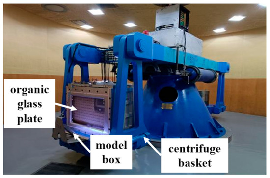
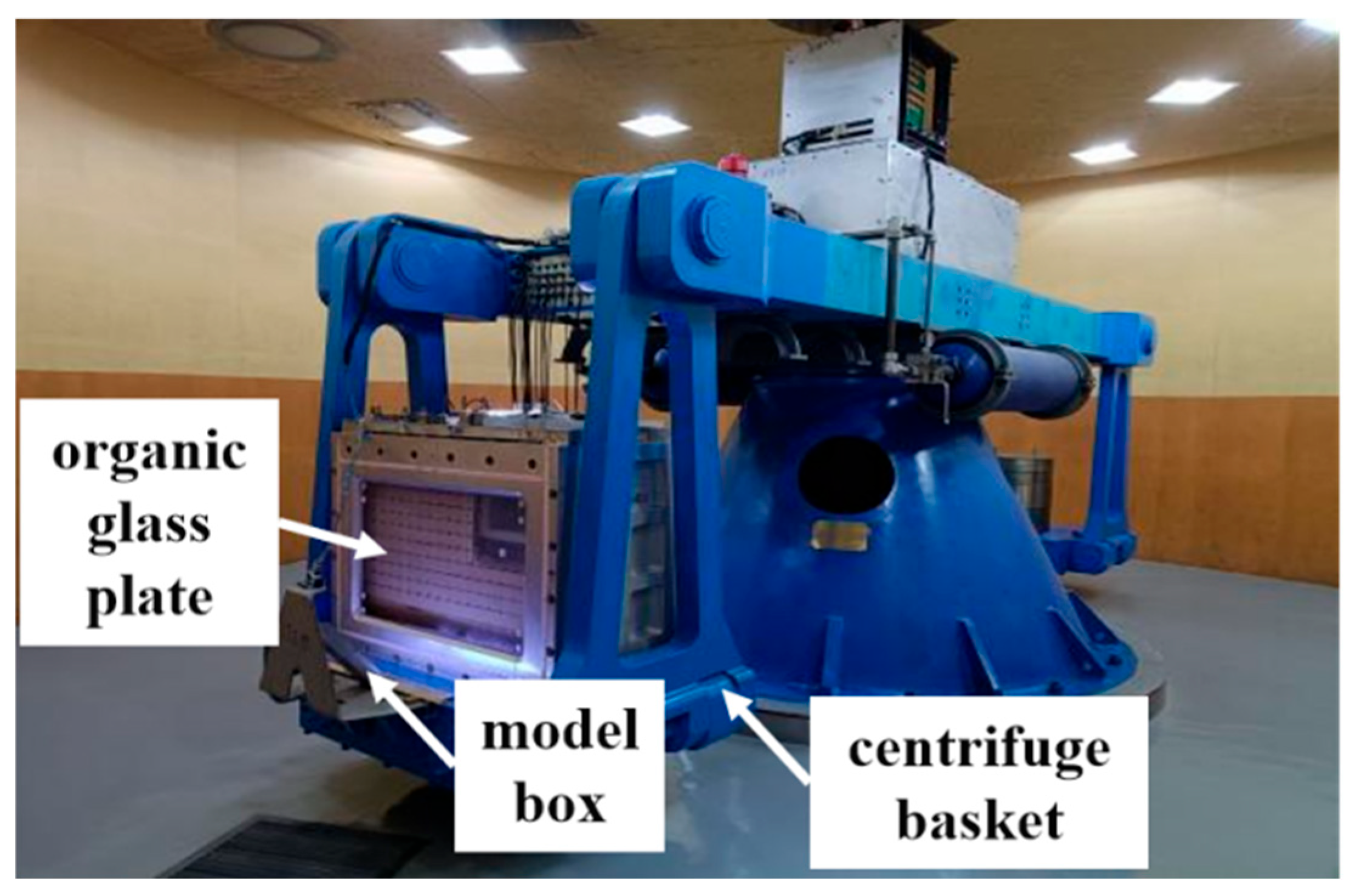
The centrifuge employed in the experiment had an effective capacity of 200 g·t, a maximum acceleration of 200 g, and an effective radius of 3.7 m. The centrifuge basket had net clearance dimensions of 1.2 m × 1.0 m × 1.5 m, while the model box measured 1.0 m in length, 0.4 m in width, and 0.8 m in height. The front face of the model box was constructed from an 80 mm thick organic glass plate, as illustrated in Figure 1.
Figure 1.
Centrifugal testing machine.
For testing purposes, the open caisson was simplified into a two-dimensional plane, with a centrifugal test scale ratio of 1:80. The prototype open caisson measured 40 m in length, 55 m in height, and 2 m in thickness. The test open caisson model was fabricated from steel and designed to be equivalent in terms of flexural rigidity (EI). The dimensional parameters of the open caisson wall model were determined using Equation (1) and are presented in Table 1.
where denotes the elastic modulus, is the thickness of the open caisson, and is Poisson’s ratio. The subscript refers to the prototype material, while the subscript denotes the model material.
Table 1.
Parameters of the open caisson model.
2.2. Test Soil Sample
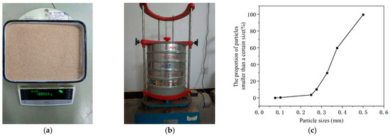
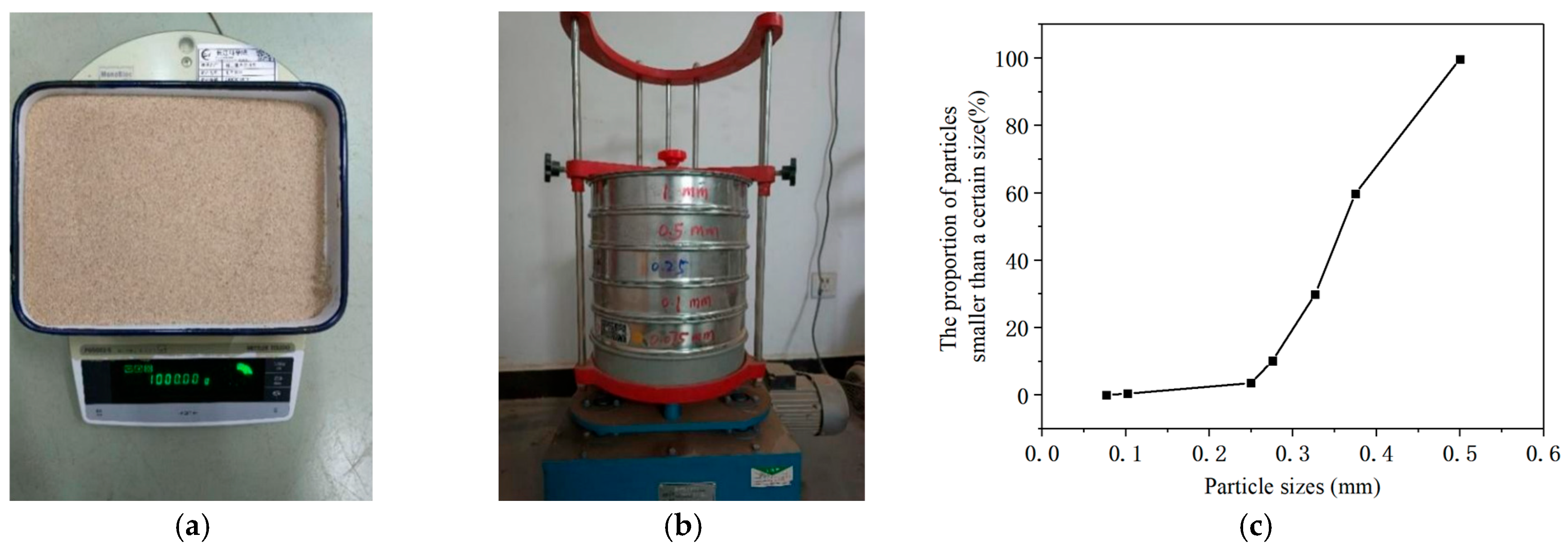
The soil sample used in the centrifugal model test of the open caisson was fine sand, as shown in Figure 2a. The screening test results (Figure 2b) indicated that the maximum particle size was less than 0.5 mm, while the particle sizes corresponding to 60%, 30%, and 10% finer fractions were 0.375 mm, 0.325 mm, and 0.275 mm, respectively. The average particle size was approximately 0.35 mm. The coefficient of uniformity (Cu) was 1.36, and the coefficient of curvature (Cc) was 1.02. The grain size distribution curve of the fine sand sample is presented in Figure 2c. A direct shear test determined the friction angle of the sample to be 30.2°, with a cohesion value of 0.4 kPa.
Figure 2.
Particle size distribution of the fine sand sample: (a) fine sand, (b) screening test, and (c) particle size distribution curve.
2.3. Test Conditions
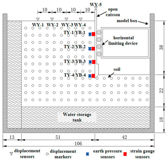
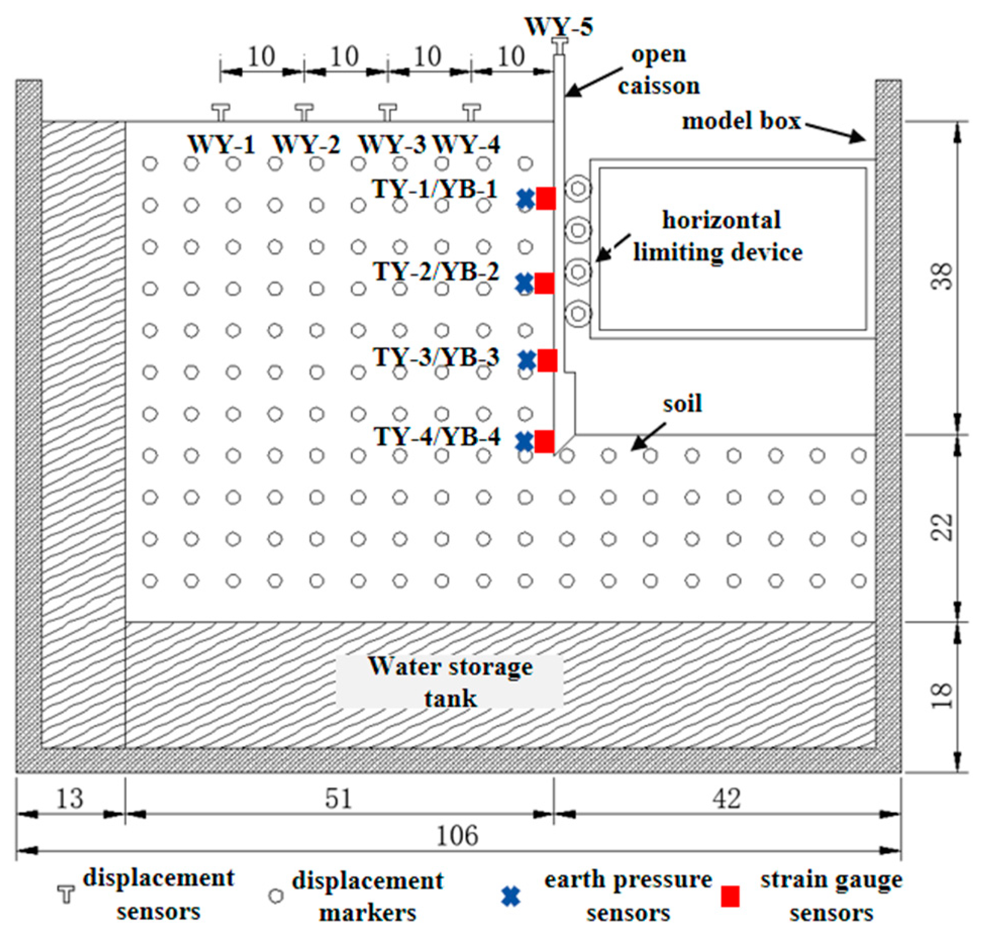
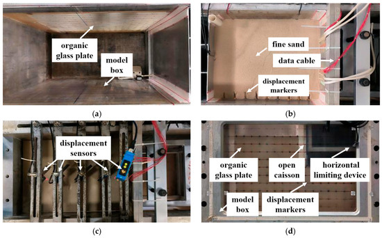
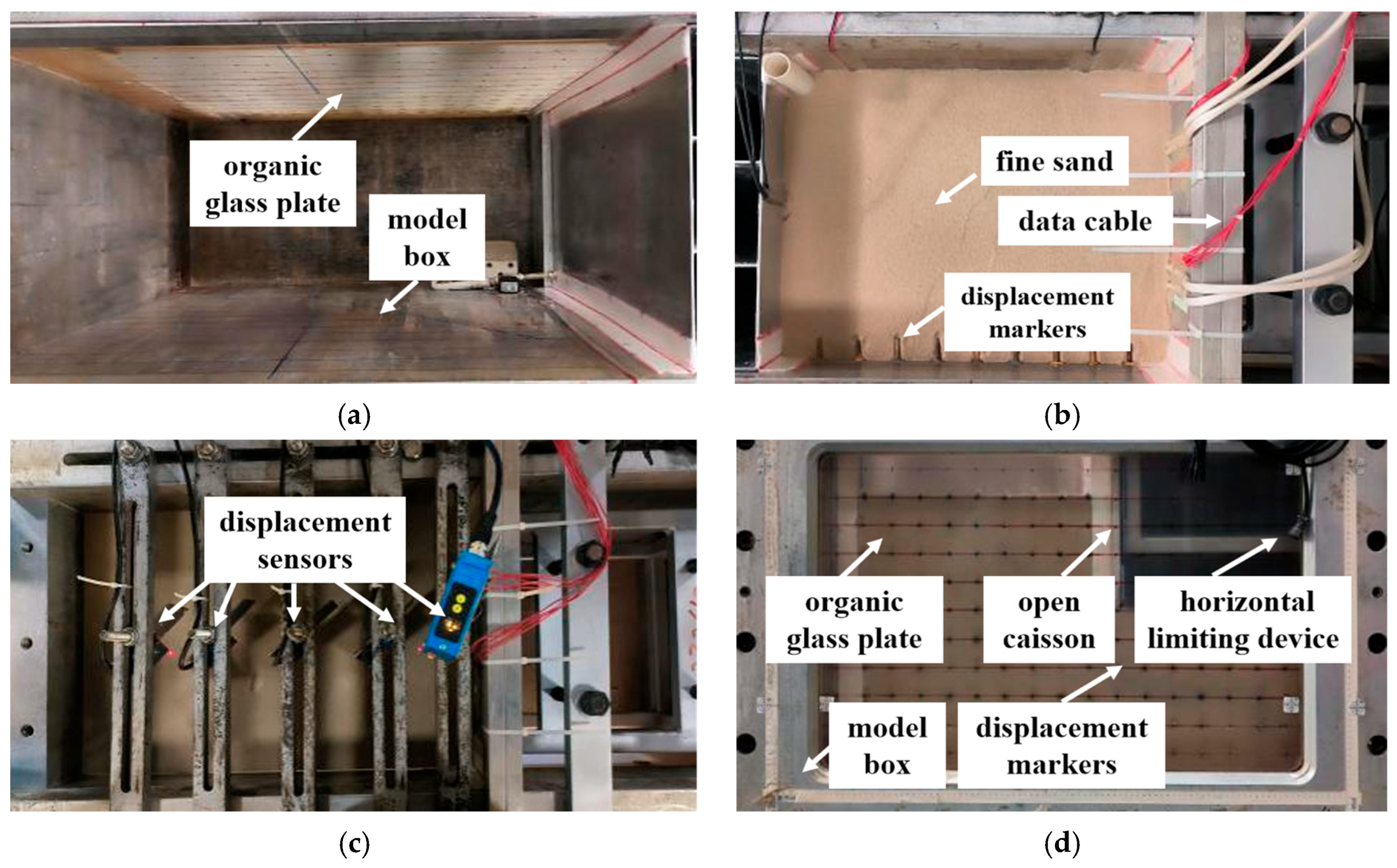
The fine sand sample was placed layer by layer according to the specified density, with clear soil displacement markers installed. The total height of the filled soil was 60 cm, consisting of a 22 cm lower layer and a 38 cm upper layer. After placement of the lower soil, the open caisson model was fixed within the model box, with its 2-cm cutting edge fully embedded into the lower soil. A horizontal limiting device was employed to restrain lateral movement of the open caisson model, after which the upper 38-cm soil layer was placed, as the actual structure’s high overall stiffness makes significant lateral deformation difficult to occur. The total embedded depth of the open caisson was therefore 40 cm. Prior to installation, earth pressure and strain gauge sensors were affixed to the open caisson model. These sensors, numbered TY-1–4 and YB-1–4 from top to bottom, were arranged at vertical intervals of 8 cm. The diameter of the earth pressure sensor is 16 mm, which is approximately 46 times the average particle size of the soil. This effectively eliminates the influence of soil particle size on monitoring accuracy. Settlement monitoring points were established on the soil surface at horizontal distances of 40, 30, 20, and 10 cm from the open caisson sidewall, as well as on the top surface of the open caisson model. Laser displacement sensors, numbered WY-1–5, were used to monitor settlement. The measurement accuracy of the earth pressure sensor is ±0.1% F.S., the measurement accuracy of the strain gauge is 0.1με, and the measurement accuracy of the displacement sensor is 0.1 mm. The open caisson test model and monitoring arrangement are shown in Figure 3, and the main testing procedure is presented in Figure 4.
Figure 3.
Schematic diagram of the open caisson test model and monitoring layout (cm).
Figure 4.
Main process of the model test: (a) model box, (b) layout of soil filling and displacement markers, (c) layout of settlement monitoring points, and (d) lateral displacement markers of the model.
The centrifugal test acceleration was gradually increased to 20 g, 40 g, 60 g, and 80 g, with each acceleration level maintained for 5 min to monitor open caisson settlement, sidewall earth pressure, strain, and soil displacement.
3. Test Results and Analysis
3.1. Caisson and Soil Settlement
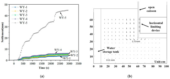
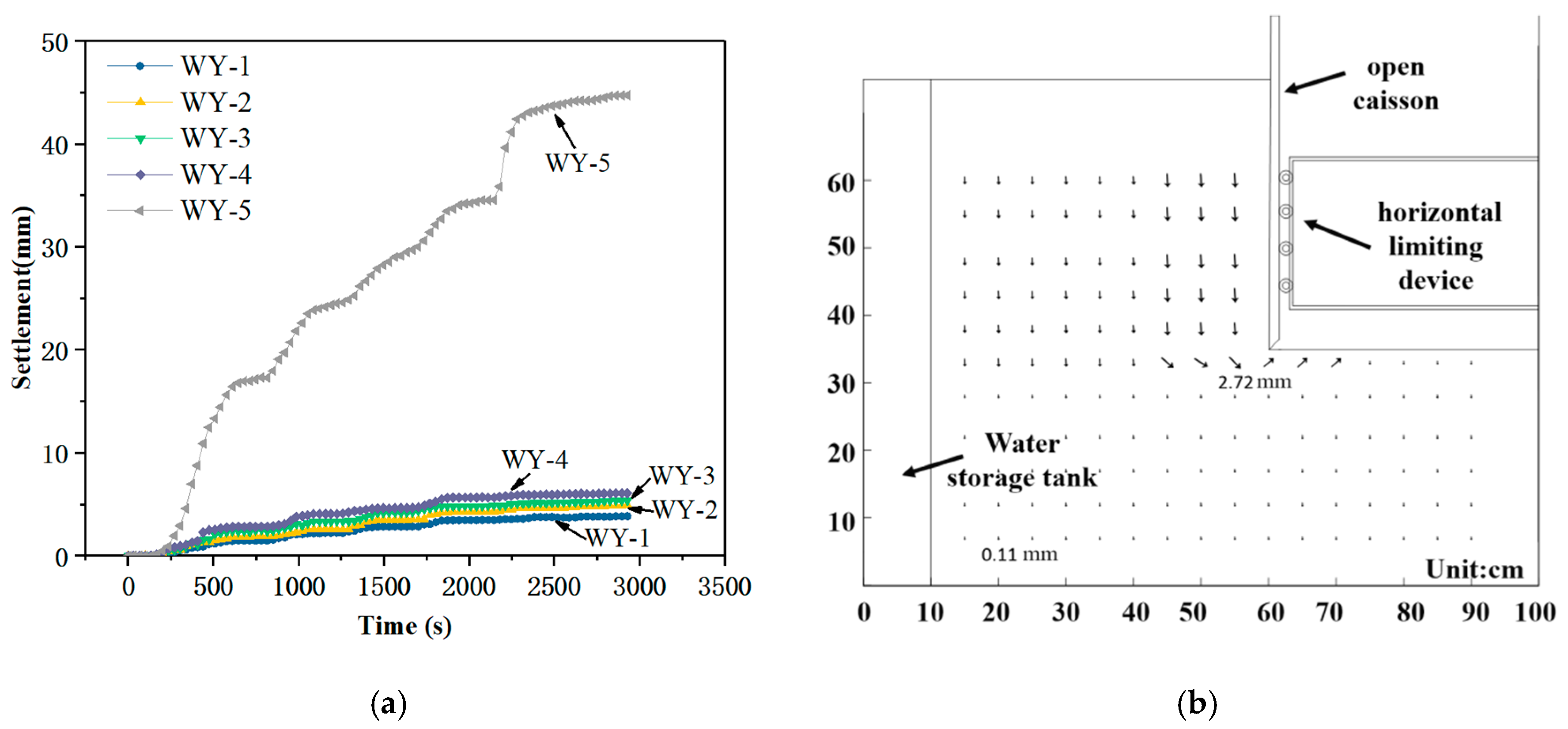
The settlement monitoring results of the open caisson and soil are presented in Figure 5a. With the progressive increase in acceleration, the soil settlement at monitoring points WY-1–4 and the open caisson settlement at WY-5 both exhibited a trend of initially increasing before stabilizing. The settlement magnitude of the surrounding soil decreased with increasing distance from the open caisson, while the open caisson settlement was significantly greater than that of the adjacent soil. These observations indicate that the open caisson–soil interface exhibited slip failure characteristics.
Figure 5.
Open caisson and soil displacements: (a) surface settlement curves of the open caisson and soil and (b) displacement vector field of the soil cross-section.
High-definition overload-resistant surveillance cameras were used to monitor soil displacement at the markers with a monitoring accuracy of 0.01 mm, and a cross-sectional displacement vector field was plotted, as shown in Figure 5b. The results indicate that soil displacement increased with proximity to the open caisson and gradually decreased from top to bottom. The soil at the open caisson cutting edge exhibited a tendency toward inward shear slippage; however, the overall displacement remained small, and no shear failure occurred within the soil mass.
3.2. Horizontal Earth Pressure on the Open Caisson Sidewall
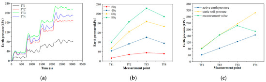
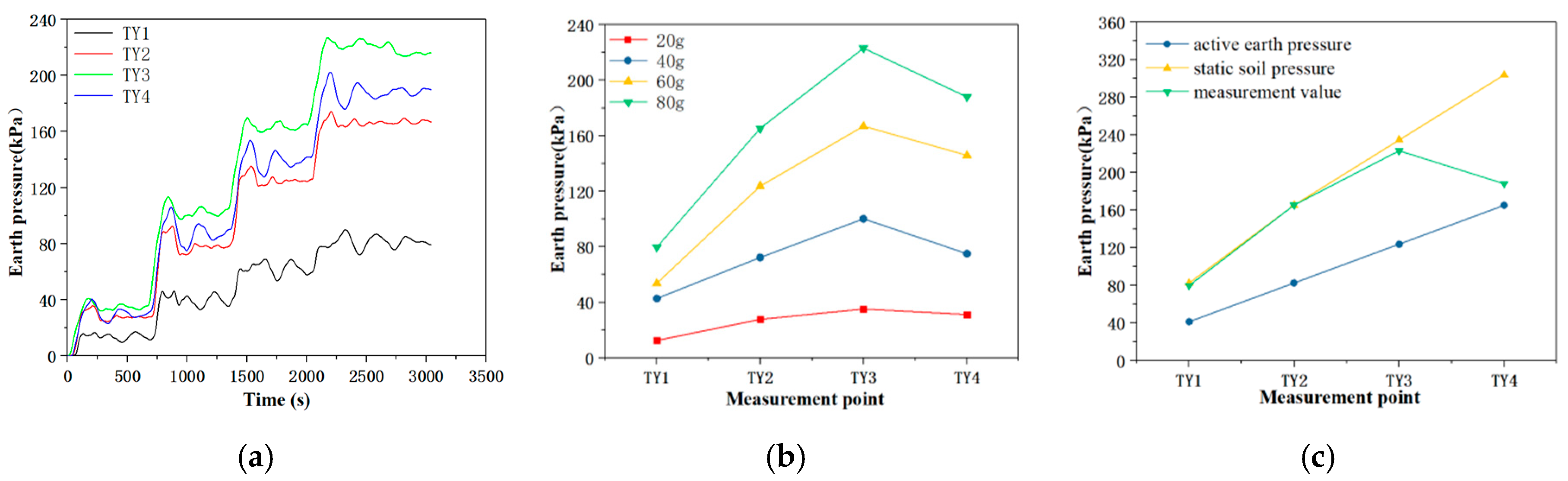
The horizontal earth pressure on the open caisson sidewall increased progressively with acceleration, as shown in Figure 6a. With increasing burial depth, the horizontal earth pressure first increased and then decreased, as illustrated in Figure 6b. At an acceleration of 80 g, the measured horizontal earth pressure values at each monitoring point were compared with the theoretical values calculated from static and active earth pressure theories, as shown in Figure 6c. The results indicated that the horizontal earth pressure along the upper sidewall was consistent with static earth pressure, while the lower sidewall pressure approached active earth pressure. The peak earth pressure was observed at approximately three-quarters of the open caisson’s embedded depth. This behavior can be attributed to the relatively shallow embedded depth of the open caisson cutting edge, where the soil at the open caisson base tended to slide inward, resulting in a gradual transition of the lower soil pressure from static earth pressure to active earth pressure.
Figure 6.
Horizontal earth pressure on the open caisson sidewall: (a) horizontal earth pressure curves at monitoring points, (b) earth pressure under different acceleration conditions, and (c) comparison of measured and theoretical values.
3.3. Skin Friction on the Open Caisson Sidewall
The strain of the open caisson sidewall increased progressively with greater soil depth and higher acceleration, as shown in Figure 7. At an acceleration of 80 g, the strain data were extracted, and the average skin friction values between monitoring points were calculated using Equation (2). The results are summarized in Table 2.
where
—Average skin friction within the monitoring point interval, kPa;
—Elastic modulus of the open caisson model, kPa;
—Strain difference between adjacent monitoring points, i.e., ;
—Interface width of the open caisson model, m;
—Distance between adjacent monitoring points, m.
Figure 7.
Strain monitoring curves.
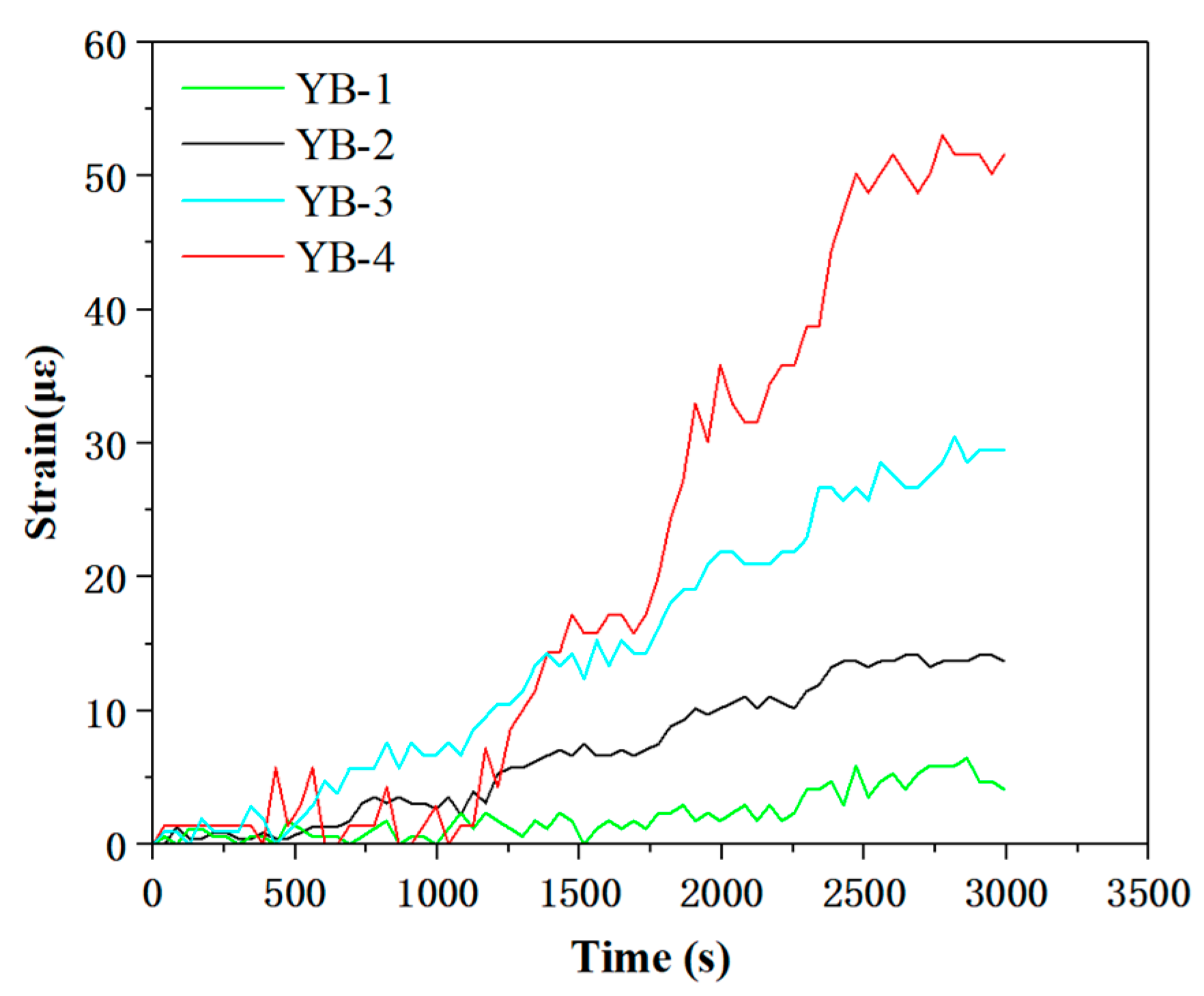
Table 2.
Strain and skin friction values at measuring points under 80 g acceleration.
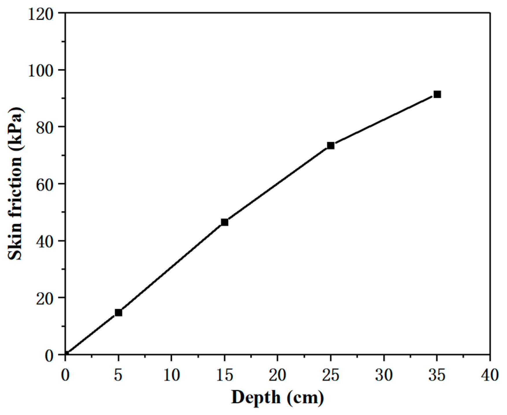
The variation of sidewall skin friction with depth is shown in Figure 8. Skin friction increased with burial depth, although the rate of increase diminished near the open caisson base. Based on the monitored horizontal earth pressure values along the open caisson sidewall, the ratio of the average skin friction within each monitoring interval to the corresponding average earth pressure was calculated using Equation (3), yielding the interface friction coefficient. The open caisson–soil interface friction angle was then determined using Equation (4). The calculated interface friction coefficient was 0.34, corresponding to a friction angle of 19°, which was approximately 0.63 times that of the fine sand sample.
where
—Average horizontal earth pressure within the monitoring point interval, kPa;
—Interface friction coefficient;
—Friction angle at the caisson–soil interface, °.
Figure 8.
Curve of skin friction with depth.
3.4. Calculation Method for Open Caisson Skin Friction
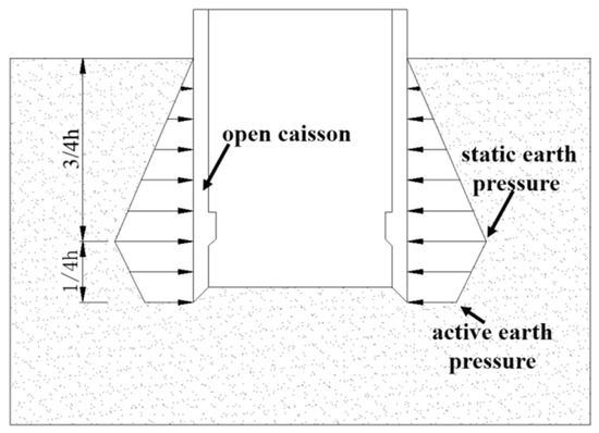
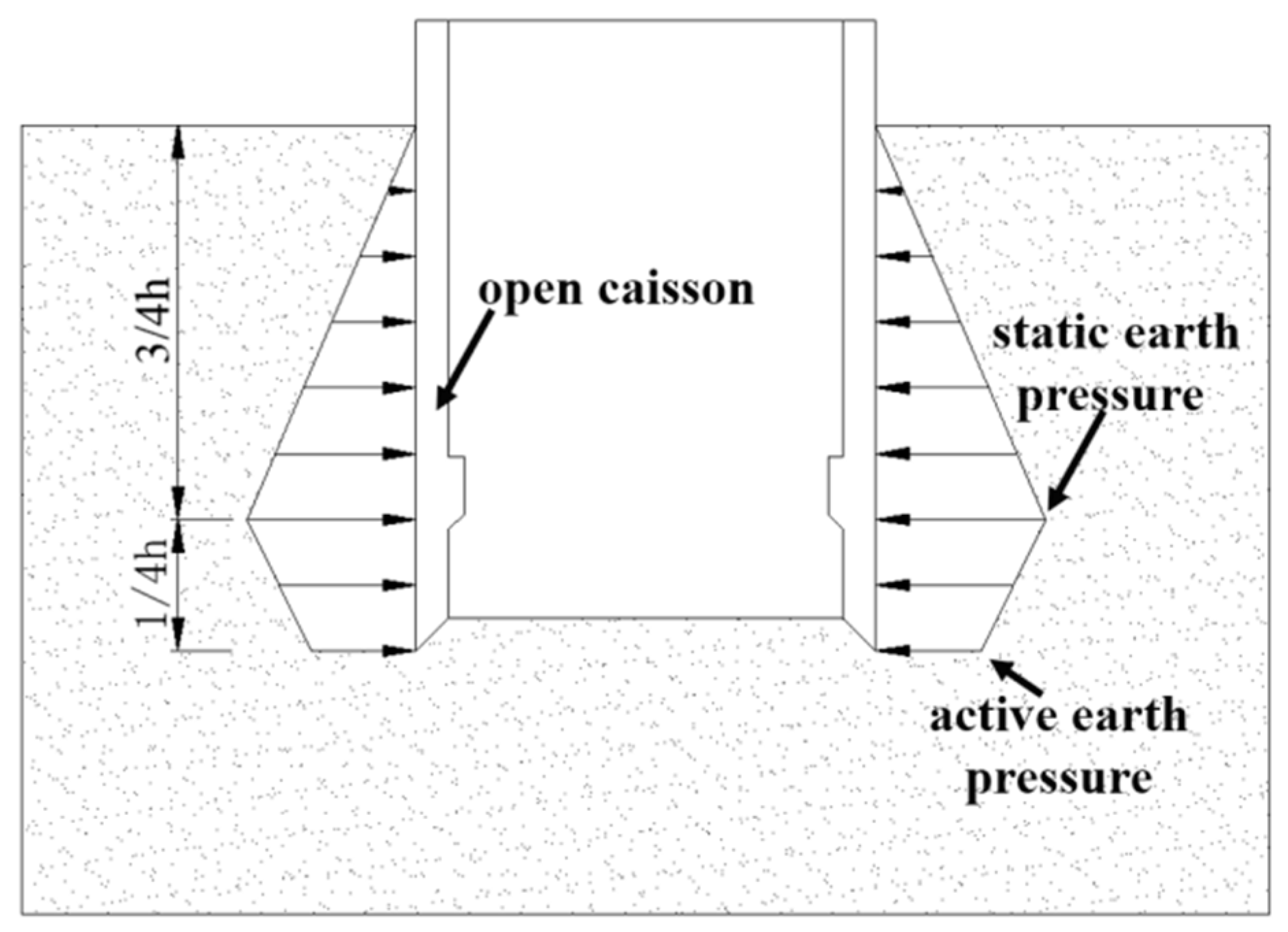
Based on the centrifugal test results, the horizontal earth pressure on the open caisson sidewall within the upper three-quarters of the embedded depth () in the sand layer could be calculated using the static earth pressure, while the earth pressure at the caisson cutting edge could be determined according to the active earth pressure. Due to the limited number of horizontal earth pressure monitoring points in the model test, when simplifying the calculation of horizontal earth pressure, it is assumed that the earth pressure varies linearly from 3/4 to of the penetration depth of the open caisson, as shown in Figure 9.
Figure 9.
Simplified model of horizontal earth pressure distribution on the open caisson sidewall.
The static earth pressure on the open caisson sidewall at a burial depth of is as follows:
The active earth pressure on the open caisson sidewall at a burial depth of is given by the following:
The earth pressure on the open caisson sidewall at different burial depths is expressed as follows:
The frictional resistance of the open caisson sidewall at different burial depths is as follows:
The earth pressure on the open caisson sidewall is as follows:
If the open caisson–soil interface friction angle is 0.63 times the friction angle of the soil, then the skin friction on the open caisson sidewall can be given as follows:
4. Engineering Application
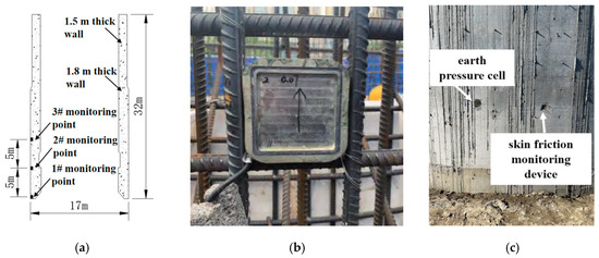
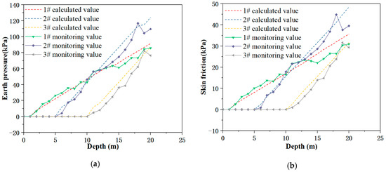
This study focused on the No. 1 open caisson of a sewage treatment plant project, which served as a pipe-jacking reception shaft. The open caisson was circular, with a diameter of 17 m and a height of 32 m. The lower section of the open caisson wall was 1.8 m thick, while the upper section was 1.5 m thick. The strata in the open caisson area, from top to bottom, consisted of silty clay, medium sand, and coarse sand. The distribution and parameters of the soil layers are presented in Table 3. Three earth pressure cells and three skin friction monitoring devices were installed along the open caisson wall at distances of 0, 5, and 10 m above the cutting edge, corresponding to measuring points 1#, 2#, and 3#. Each earth pressure cell was paired with a skin friction monitoring device at the same elevation, with a horizontal spacing of 1 m. The monitoring layout is shown in Figure 10.
Table 3.
Soil layer distribution and soil parameters.
Figure 10.
Layout of earth pressure and skin friction devices: (a) monitoring point locations, (b) installation of skin friction devices, and (c) on-site device layout.
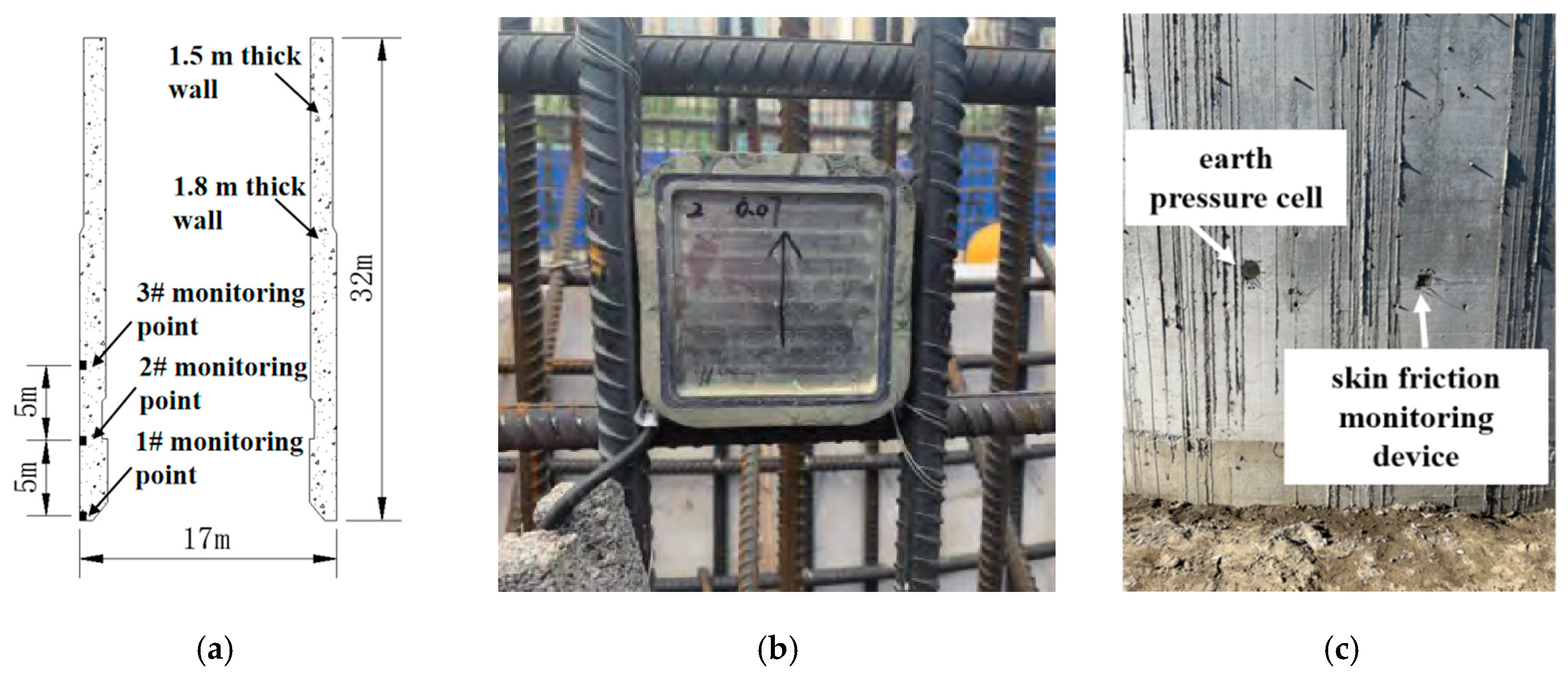
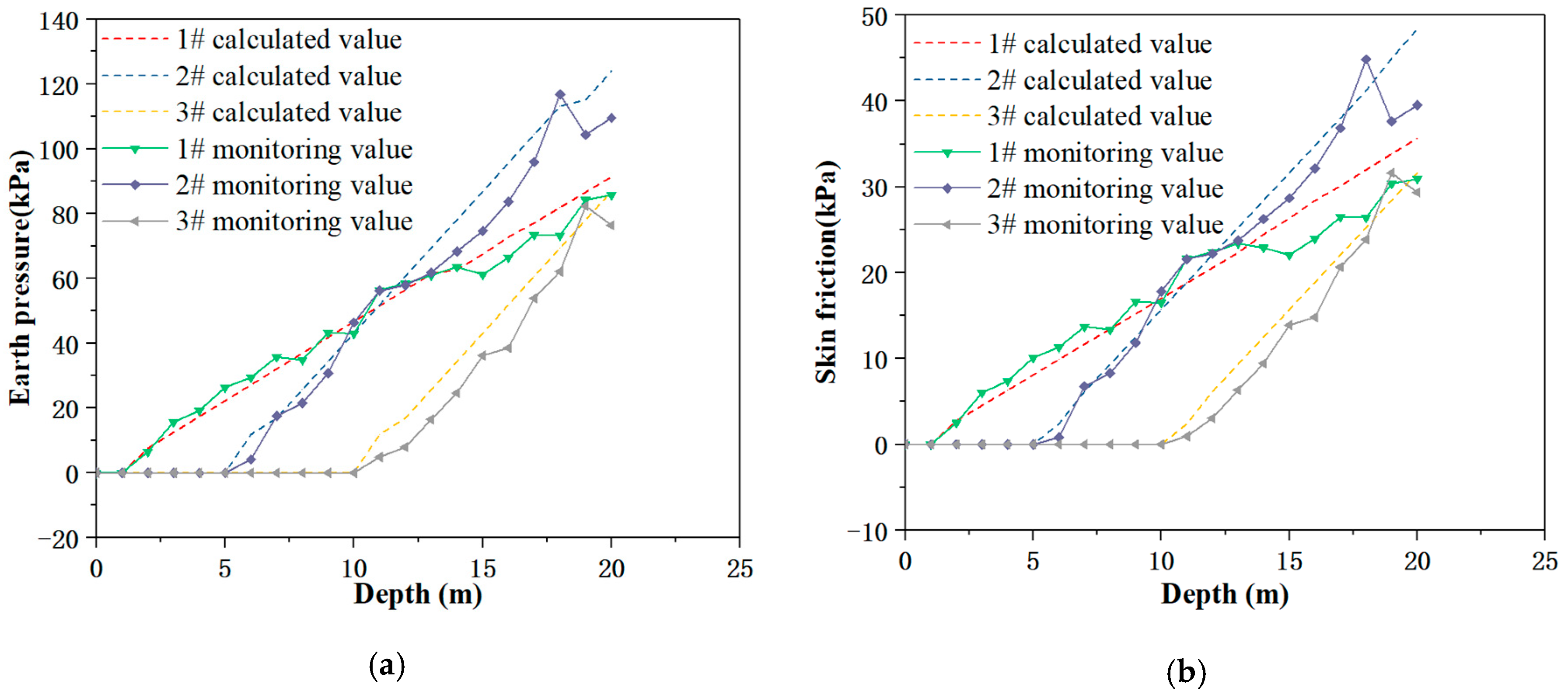
Using Equations (7) and (8), the sidewall earth pressure and skin friction of the open caisson at monitoring points 1#, 2#, and 3# were calculated for different depths and compared with the corresponding monitored values. The comparison curves of calculated and measured sidewall earth pressure and skin friction are presented in Figure 11a,b, respectively. The theoretical results showed good agreement with the monitoring data, thereby verifying the accuracy of the proposed calculation method for sidewall earth pressure and skin friction.
Figure 11.
Comparison curves between the calculated and monitored values of earth pressure and skin friction: (a) earth pressure and (b) skin friction.
5. Conclusions
Based on the centrifugal model test, the interaction mechanism between the open caisson and the surrounding fine sandy soil was analyzed, and the distribution characteristics of sidewall earth pressure and skin friction were determined. Theoretical calculation formulas for horizontal earth pressure and skin friction were developed and subsequently verified through field tests. The main conclusions are as follows:
1. During the sinking process, the settlement of the open caisson was significantly greater than that of the surrounding soil, and the open caisson–soil interface exhibited slip failure characteristics. The soil at the open caisson cutting edge showed a tendency toward inward shear slippage.
2. The horizontal earth pressure on the open caisson sidewall corresponded to the static earth pressure in the upper section and gradually transitioned toward the active earth pressure in the lower section. The maximum earth pressure was observed at approximately three-quarters of the embedded depth.
3. The skin friction increased progressively with burial depth, although the rate of increase diminished near the base of the open caisson. The friction angle at the open caisson–soil interface was approximately 0.63 times that of the soil friction angle.
4. Based on the distribution characteristics of earth pressure and skin friction obtained from the centrifugal test, corresponding theoretical calculation formulas were established. The accuracy of these formulas was verified through field tests, providing valuable references for the construction of large open caisson projects.
5. Due to the insufficient validation of the variation law of earth pressure from 3/4 h to h, the theoretical calculation formulas for earth pressure and side friction, established based on the assumption of linear variation, can be used by engineers for simplified calculations. The present study focused solely on the interaction between the open caisson and the silty fine sand formation. Further investigation is needed into the mechanisms during sinking in cohesive soil layers, as well as in mixed formations of sandy and cohesive soils.
Author Contributions
Conceptualization, D.L. and Y.Z.; methodology, D.L.; formal analysis, W.L.; investigation, F.J.; resources, D.L.; data curation, J.X.; writing—original draft preparation, D.L.; writing—review and editing, D.L.; project administration, D.L.; funding acquisition, D.L. and Y.Z. All authors have read and agreed to the published version of the manuscript.
Funding
This research was funded by the Hubei Natural Science Foundation Youth Project (Grant No. 2024AFB409) and the National Natural Science Foundation of China (Grant No. 42462029).
Data Availability Statement
All the research data can be obtained from this manuscript.
Conflicts of Interest
Authors Dejie Li, Fuquan Ji and Jing Xiao are employed by CCCC Second Harbour Engineering Co., Ltd. Author Dejie Li is employed by CCCC Wuhan Harbour Engineering Design and Research Co., Ltd. Weijia Liu is employed by CCCC Wuhan Zhixing International Engineering Consulting Co., Ltd. The remaining authors declare that the research was conducted in the absence of any commercial or financial relationships that could be construed as a potential conflict of interest.
References
- Yan, X.; Zhan, W.; Hu, Z.; Xiao, D.; Yu, Y.; Wang, J. Field study on deformation and stress characteristics of large open caisson during excavation in deep marine soft clay. Adv. Civ. Eng. 2021, 2021, 7656068. [Google Scholar] [CrossRef] [Scilit]
- Konkol, J.; Mikina, K. Some aspects of shear behavior of soft soil-concrete interfaces and its consequences in pile shaft friction modeling. Materials 2021, 14, 2578. [Google Scholar] [CrossRef] [Scilit] [PubMed]
- Aldaeef, A.A.; Rayhani, M.T. Pile-soil interface characteristics in ice-poor frozen ground under varying exposure temperature. Cold Reg. Sci. Technol. 2021, 191, 103377. [Google Scholar] [CrossRef] [Scilit]
- Templeman, J.O.; Phillips, B.M.; Sheil, B.B. Cutting shoe design for open caissons in sand: Influence on vertical bearing capacity. Proc. Inst. Civ. Eng.-Geotech. Eng. 2023, 176, 58–73. [Google Scholar] [CrossRef] [Scilit]
- Suppakul, R.; Chavda, J.T.; Jitchaijaroen, W.; Keawsawasvong, S.; Rattanadecho, P. Soft computing-based models for estimating undrained bearing capacity factor of open Caisson in heterogeneous clay. Geotech. Geol. Eng. 2024, 42, 5335–5361. [Google Scholar] [CrossRef] [Scilit]
- Aswin, L.; Chang-Yu, O. Stress paths in deep excavations under undrained conditions and its influence on deformation analysis. Tunn. Undergr. Space Technol. 2017, 63, 118–132. [Google Scholar] [CrossRef] [Scilit]
- Jiang, B.-N.; Wang, M.-T.; Chen, T.; Zhang, L.-L.; Ma, J.-L. Experimental study on the migration regularity of sand outside a large, deep-water, open caisson during sinking. Ocean Eng. 2019, 193, 45–53. [Google Scholar] [CrossRef] [Scilit]
- Yea, G.G.; Kim, T.H. Vertical cutting edge forces measured during the sinking of pneumatic caisson. Mar. Georesour. Geotechnol. 2012, 30, 103–121. [Google Scholar] [CrossRef] [Scilit]
- Kayadelen, C.; Altay, G.; Öztürk, M.; Önal, Y. Experimental evaluation of the pull-out behavior of suction caissons in saturated sand soil. Ocean Eng. 2023, 286, 115609. [Google Scholar] [CrossRef] [Scilit]
- Li, D.Y.; Li, S.S.; Zhang, Y.K.; Chen, F.Q. Earth pressure distribution and sand deformation around modified suction caissons (MSCs) under monotonic lateral loading. China Ocean Eng. 2019, 33, 198–206. [Google Scholar] [CrossRef] [Scilit]
- Yang, B.; Shi, Q.; Zhou, H.; Qin, C.; Xiao, W. Study on distribution of sidewall earth pressure on open caissons considering soil arching effect. Sci. Rep. 2023, 13, 10657. [Google Scholar] [CrossRef] [Scilit] [PubMed]
- Ilori, A.O.; Udoh, N.E.; Umenge, J.I. Determination of soil shear properties on a soil to concrete interface using a direct shear box apparatus. Int. J. Geo-Eng. 2017, 8, 17. [Google Scholar] [CrossRef] [Scilit]
- Wang, P.; Yin, Z.Y.; Zhou, W.H.; Chen, W.B. Micro-mechanical analysis of soil-structure interface behavior under constant normal stiffness condition with DEM. Acta Geotech. 2022, 17, 2711–2733. [Google Scholar] [CrossRef] [Scilit]
- Harireche, O.; Naqash, M.T.; Farooq, Q.U. A full numerical model for the installation analysis of suction caissons in sand. Ocean Eng. 2021, 234, 109173. [Google Scholar] [CrossRef] [Scilit]
- Zhang, J. Numerical simulation on the whole sinking process of open caisson with an improved SPH method. Math. Probl. Eng. 2021, 2021, 6699880. [Google Scholar] [CrossRef] [Scilit]
- Nicotera, M.V.; Russo, G. Monitoring a deep excavation in pyroclastic soil and soft rock. Tunn. Undergr. Space Technol. 2021, 117, 104130. [Google Scholar] [CrossRef] [Scilit]
- Ou, C.Y.; Hsieh, P.G. A simplified method for predicting ground settlement profiles induced by excavation in soft clay. Comput. Geotech. 2011, 38, 987–997. [Google Scholar] [CrossRef] [Scilit]
- Tian, W.; Li, H.; Wang, Y.; Zhu, Y.; Zhu, H.; Li, K. Data-Driven Decision Algorithm for Open Caisson Foundation Construction. Adv. Civ. Eng. 2024, 2024, 9373931. [Google Scholar] [CrossRef] [Scilit]

Disclaimer/Publisher’s Note: The statements, opinions and data contained in all publications are solely those of the individual author(s) and contributor(s) and not of MDPI and/or the editor(s). MDPI and/or the editor(s) disclaim responsibility for any injury to people or property resulting from any ideas, methods, instructions or products referred to in the content. |
© 2026 by the authors. Licensee MDPI, Basel, Switzerland. This article is an open access article distributed under the terms and conditions of the Creative Commons Attribution (CC BY) license.