


Abstract
This paper proposes a dual-band, full-polarized (dual-sense circular polarization and arbitrary linear polarization) annular-ring slot antenna centered at 2.4 GHz and 5.8 GHz, which effectively overcomes the limitations of narrow bandwidth and limited polarization diversity in conventional designs. By employing an eccentric annular-ring slot and two orthogonal 50-ohm patches, the antenna achieves dual-band circular polarization (CP) radiation with single-port feeding. Based on the theory of orthogonal dual-circular polarization synthesis, arbitrary linear polarization (LP) can be generated by adjusting the phase difference when both ports are fed. The measured results show that the 10 dB return loss bandwidth of LP spans 2–2.8 GHz (relative bandwidth of 33.3%) and 4.5–7.5 GHz (relative bandwidth of 50%), with polarization isolation exceeding 50 dB. For CP mode, the measured bandwidth (for 10 dB return loss and 3 dB axial ratio) ranges from 2.24 to 2.58 GHz (relative bandwidth of 14.1%) and from 5.1 to 6.6 GHz (relative bandwidth of 25.64%), with polarization isolation greater than 15 dB. The proposed antenna simultaneously features a high frequency ratio (2.42), full polarization, high polarization isolation, a low profile (0.008 λ0), and bidirectional radiation, which can meet the urgent demand of modern information systems for dual-band, full-polarized antennas.
1. Introduction
Modern multi-functional wireless communication systems, such as Wi-Fi 6, satellite navigation, and unmanned aerial vehicle (UAV) measurement and control, have an increasing demand for applications with dual-band, polarization diversity, and miniaturized antennas [1]. The dual-band full-polarized antenna based on microstrip structure is one of the key solutions [2].
The design methods of typical dual-band microstrip antennas include structural regulation [3,4], mode control [5], feeding network design [6], metamaterial application [7], and shared aperture [8]. Among them, the slot-loading adopted in [3] and the multi-patch employed in [4] are the two most mainstream methods for structural regulation, which are theoretically mature and widely applied. To balance performance, size, and cost, designers often combine multiple techniques in practical engineering applications [9,10,11]. A dual-band microstrip patch antenna proposed in [9] achieved dual-band characteristics by adopting a multi-patch stacking design and incorporating slots on the main radiating patch. A dual-band circularly polarized annular ring patch antenna introduced in [10] produced resonance at the upper and lower frequencies by the inner and outer annular rings, and impedance matching was obtained by adjusting the distance between the feeding point and the shorting pins. A low-profile slotted patch antenna in [11] formed a Fabry-Pérot resonant cavity with the slotted patch and the metasurface superstrate, thereby realizing dual-band applications in the C-band and X-band.
The development of dual-band multi-polarized antennas has followed two primary technical paths. The first approach utilizes single-port feeding or reconfigurable elements. For instance, the compact antenna in [12] employed a PIN diode to switch between CP and LP states, yet it provided only a single, fixed polarization mode per operating band and exhibited a narrow frequency ratio. Similarly, the polarization reconfigurable antenna in [13] achieved multiple switchable states but could not generate continuously arbitrary linear polarization and was constrained by a very low frequency ratio.
The second approach relies on multi-port feeding schemes. The design in [14] achieved high-isolation dual-linear polarization but lacked the capability for circular polarization. The tri-polarized antenna in [15] offered three orthogonal linear polarizations but similarly could not radiate CP waves. Furthermore, the aperture-shared array in [16] excelled in its self-diplexing function for dual-sense CP but was incapable of generating linear polarization in either frequency band.
In summary, existing solutions [12,13,14,15,16] are unable to simultaneously support full-polarization states (dual-sense CP and arbitrary LP) across two widely separated bands within a simple, single-layer structure. They typically compromise on one or more key aspects: polarization completeness, frequency ratio, bandwidth, or architectural complexity. To the best of the authors’ knowledge, among the prior research, few microstrip antennas have concurrently achieved dual-band and full-polarization characteristics over a wide frequency range with a single-layer structure.
A dual-band full-polarized annular-ring slot antenna with high polarization isolation is proposed in this paper, achieving a high resonant frequency ratio of 2.42. Methods of slot-loading, multi-patch, and feeding structure are comprehensively employed. The proposed antenna incorporates a dual-port feeding structure to realize the conversion between LP and CP. The two orthogonal centrally positioned feeding lines are simultaneously used as radiation patches. When the single-port is feeding independently, the antenna directly radiates circularly polarized waves through the interaction of orthogonal radiation patches with the eccentric ring slot on the ground plane. When dual-port feeding is activated, based on the orthogonal dual circular polarization synthesis theory, the left-handed and right-handed circular polarization waves of the two ports will be combined into a single linearly polarized wave. Moreover, linear polarization with any angle can be achieved simply by adjusting the phase difference between the two ports. To verify the effectiveness of the proposed antenna structure, a physical antenna has been fabricated and measured in this paper. The measured results show excellent agreement with simulations, validating the following key features of the proposed antenna:
- Dual-band operation with a high frequency ratio of 2.42.
- Full-polarization capability, supporting both dual-sense CP and arbitrary angle LP.
- Exceptional polarization isolation exceeding 50 dB for LP and 15 dB for CP states.
- A low profile of 0.008 λ0 and a bidirectional radiation pattern.
These attributes collectively address critical challenges in modern multi-functional integrated systems.
2. Antenna Design and Analysis
2.1. Antenna Configuration
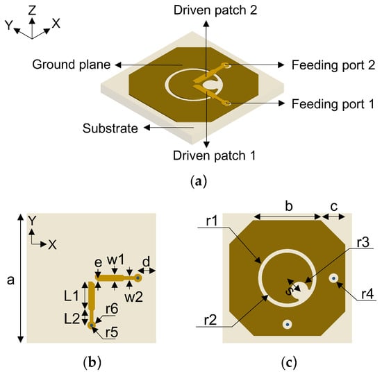
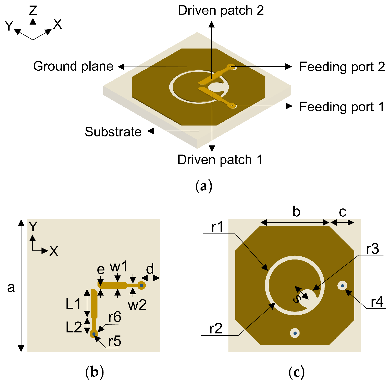
Figure 1 shows the configuration of the proposed dual-band full-polarized annular-ring slot antenna. The proposed antenna consists of driven patch 1 and driven patch 2, the ground plane, and the substrate. PTFE with a glass-reinforced RF circuit material with a relative permittivity of 2.55, a loss tangent of 0.001, and a thickness of 1 mm is used in the design.
Figure 1.
Geometry of the proposed antenna: (a) Perspective view. (b) Top view. (c) Bottom view.
A dual-port coaxial feeding structure is employed in this paper. Two centrally placed orthogonal 50-ohm microstrip feeding lines also serve as driven patches 1 and 2, thereby enabling the structure to fulfill the orthogonality condition in physical space inherently. By adjusting the distance between driven patches 1 and 2, two orthogonal modes with equal amplitude and a 90° phase difference can be obtained through their interaction with the ground plane under single-port feeding, thereby achieving CP at dual-band. Detailed dimensional parameters are tabulated in Table 1.
Table 1.
Detailed dimensions of the proposed antenna.
2.2. Antenna Design
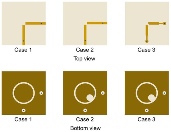
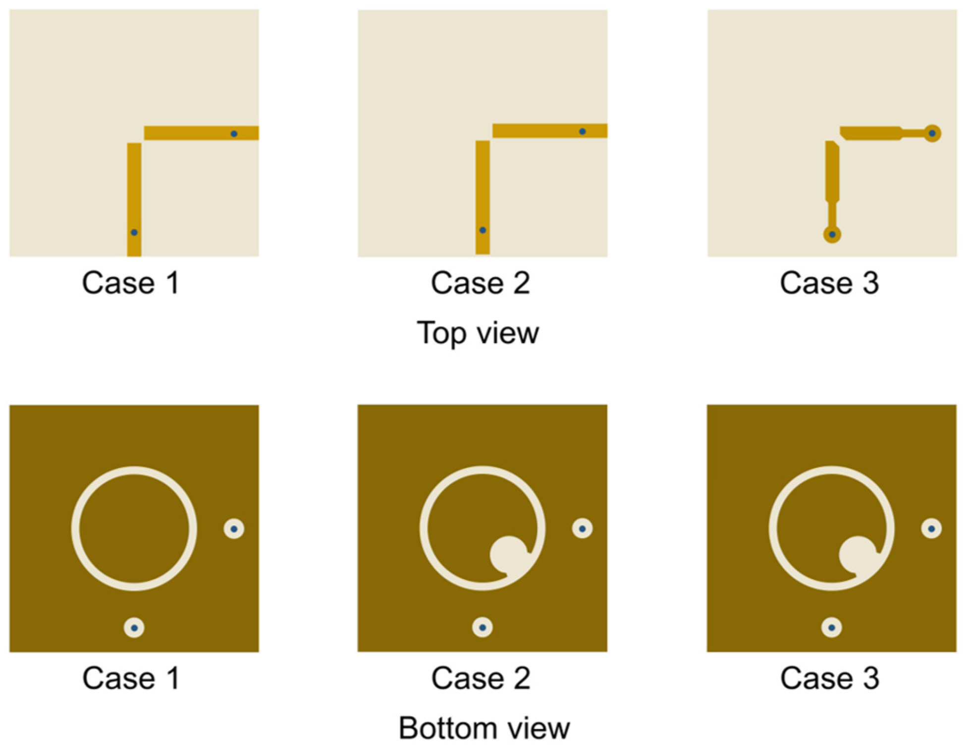
To better illustrate the operating principles of the proposed antenna, the preliminary design process is depicted in Figure 2, where the three antenna iterations are designated as Case 1, Case 2, and Case 3. The commercial software High-Frequency Structure Simulator (HFSS) 2023 was employed for modeling and simulating. All results are obtained from converged simulations in HFSS. The axial ratios presented in this paper correspond to measurements at the main radiation direction of phi = 0° and theta = 0°. Due to the structural symmetry, only the CP results under the independent feeding of port 1 and the LP results of 0° angle are reported in the subsequent analysis.
Figure 2.
Three antenna iterations in the preliminary design process.
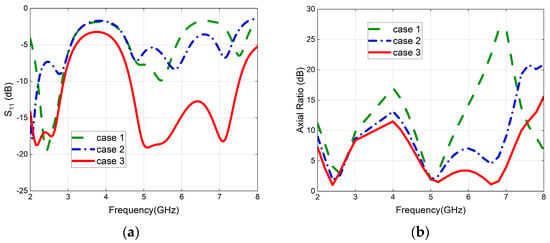
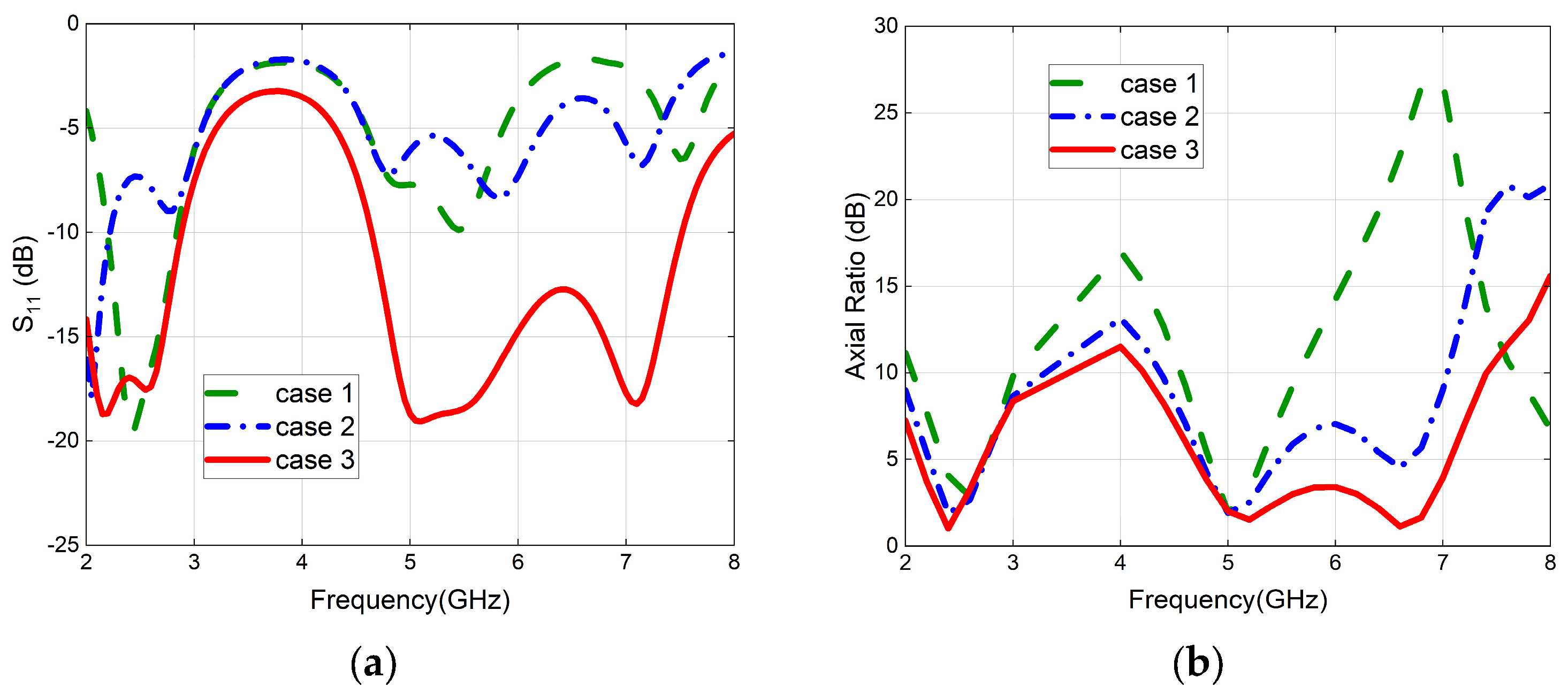
Figure 3 presents the comparison of the reflection coefficients and axial ratios of the three cases. Among these iterations, Case 1 features a conventional annular-ring slot at the center of the ground plane. Although Case 1 generates dual-band circularly polarized radiation, the axial ratio and reflection coefficient are not ideal, and the high frequency is not a desired frequency point.
Figure 3.
Comparison results of three antenna iterations: (a) Reflection coefficients. (b) Axial ratios.
To achieve a lower axial ratio, an eccentric circular slot is introduced into Case 2 based on Case 1. The axial ratio of Case 2 is significantly reduced, while the reflection coefficient fails to exhibit a notable improvement.
For further reduction in the reflection coefficient, the length of the two 50-ohm patches is shortened, and a new design is implemented in Case 3, which is modified based on Case 2. The results in Figure 3 illustrate that both the axial ratio and reflection coefficient of Case 3 are notably reduced.
The aforementioned comparative results demonstrate that the innovative integration of dual-port feeding structure, multi-patch, and slot-based techniques not only effectively reduces the axial ratio but also extends the effective operating bandwidth.
2.3. Antenna Analysis
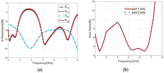
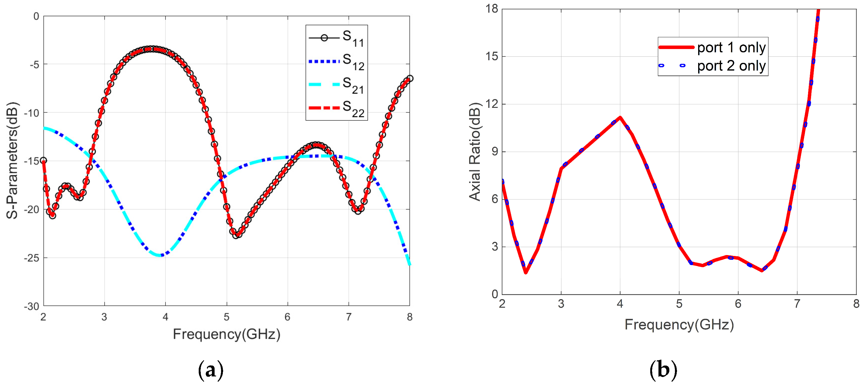
Figure 4 shows the S-parameters and axial ratio results of the finally proposed antenna. Owing to the symmetry of the design, S11 is the same as S22, and S21 is the same as S12. The simulated S11 bandwidth below −10 dB is 40% (2–2.94 GHz) for the 2.4 GHz band and 49.2% (4.7–7.67 GHz) for the 5.8 GHz band. The isolation between the two ports exceeds 10 dB, indicating good isolation between the two ports. Additionally, regardless of whether port 1 or port 2 is used for antenna feeding independently, the axial ratio results are consistent. The maximum axial ratio remains within 3 dB across the 2.25–2.6 GHz and 5–6.68 GHz, demonstrating excellent circular polarization performance.
Figure 4.
Simulated results of the proposed antenna: (a) S-parameters. (b) Axial ratios.
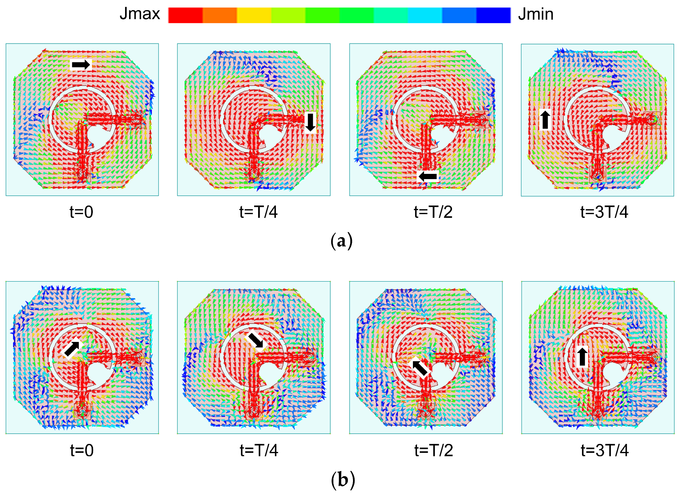
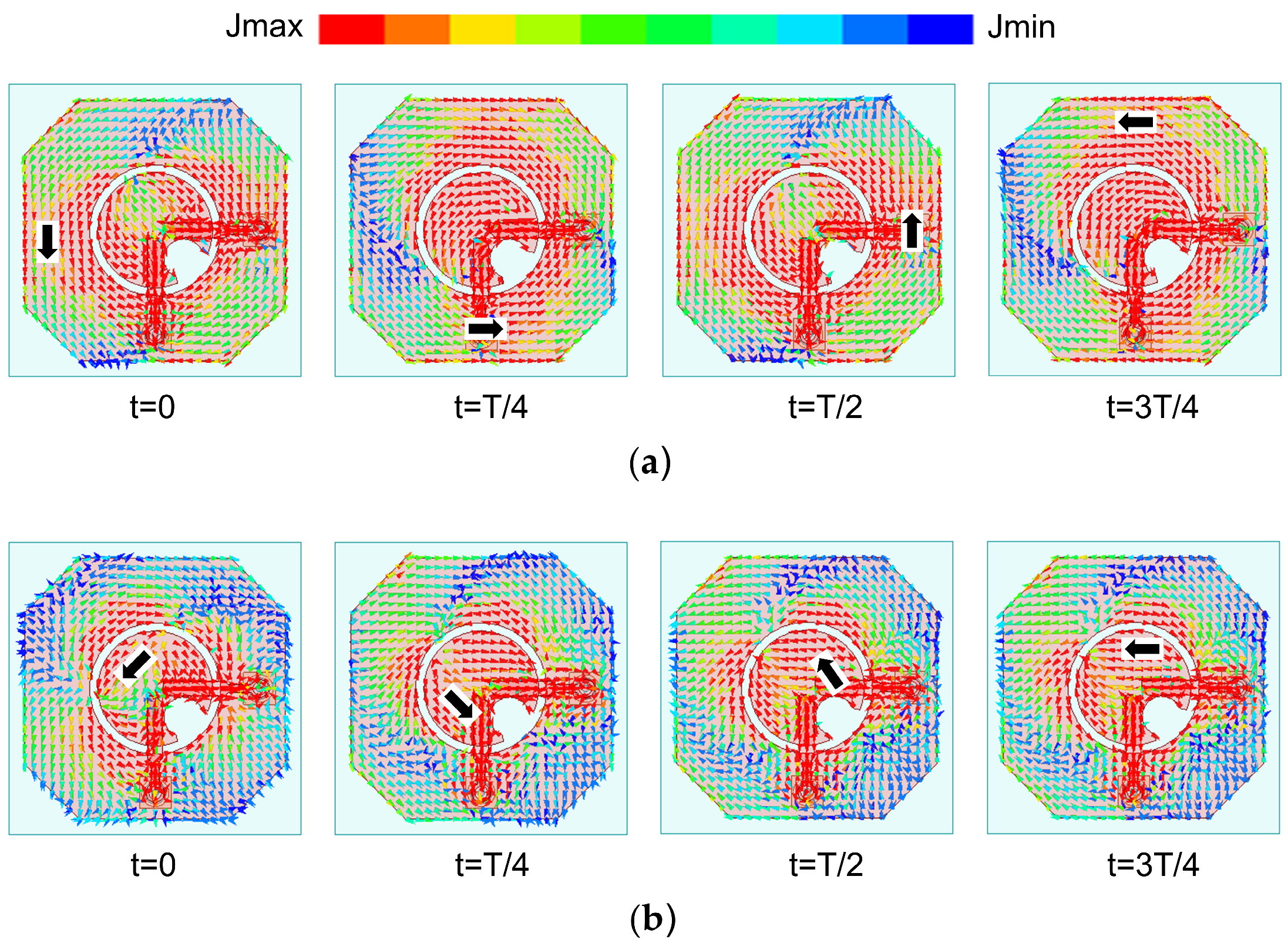
Figure 5 illustrates the surface current distribution of the proposed antenna at 2.4 GHz and 5.8 GHz when port 1 is excited independently. This figure depicts the evolution of current distributions at distinct instants in the +z direction. As exhibited by the black arrows, the surface current rotates in a clockwise direction at time points of t = 0, T/4, T/2, 3T/4, indicating left-handed circularly polarized (LHCP) radiation. In contrast, the current distribution shown in Figure 6 follows an anti-clockwise rotational trend under the excitation of port 2, exhibiting right-handed circularly polarized (RHCP) radiation. Specifically, benefiting from the inherent orthogonality of the two feeding patches, the circularly polarized waves generated in port 1 or port 2 exhibit opposite rotation directions: one isLHCP, and the other isRHCP.
Figure 5.
Simulated surface current distribution in LHCP states: (a) 2.4 GHz. (b) 5.8 GHz.
Figure 6.
Simulated surface current distribution in RHCP states: (a) 2.4 GHz. (b) 5.8 GHz.
According to the theory of orthogonal dual-circular polarization synthesis introduced in our previous article [17], two circularly polarized waves with equal amplitude and opposite rotation directions can be combined into a linearly polarized wave. The LP angle is half the initial phase difference between the left-handed and right-handed circularly polarized waves. Therefore, linear polarization in any direction can theoretically be achieved by adjusting the phase difference between the two circularly polarized waves with opposite rotations in ports 1 and 2. This further enables the continuous tuning of the linear polarization angle.
3. Experimental Results and Discussion
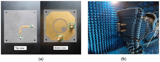
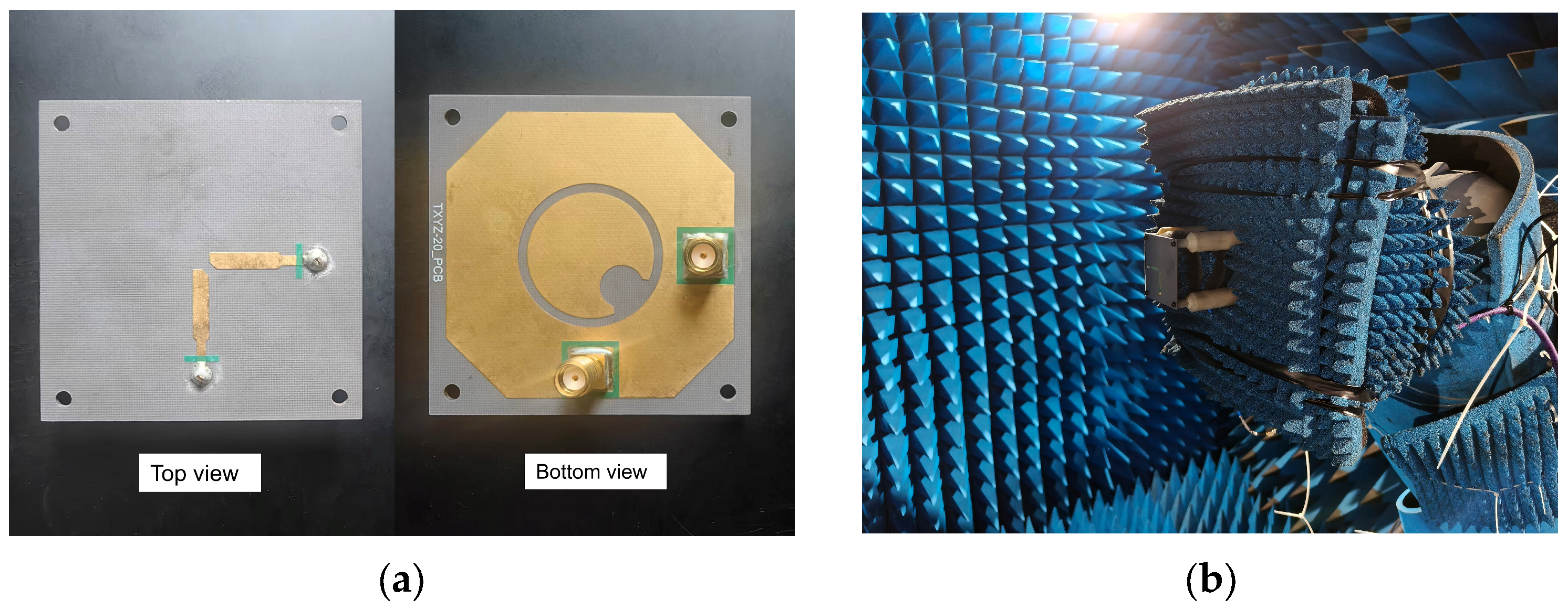
Based on the dimensional parameters in Table 1, the proposed antenna was physically fabricated and tested, as shown in Figure 7. SMA connectors were welded to ports 1 and 2. The far-field radiation measurement was conducted in a microwave anechoic chamber.
Figure 7.
Prototype of the proposed antenna: (a) Photograph. (b) Far-field measurement.
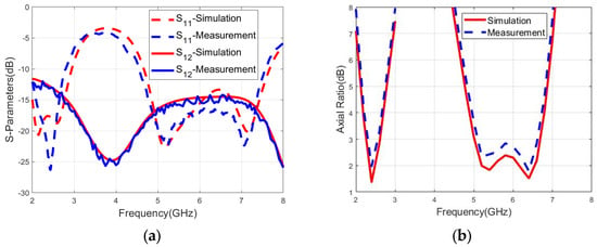
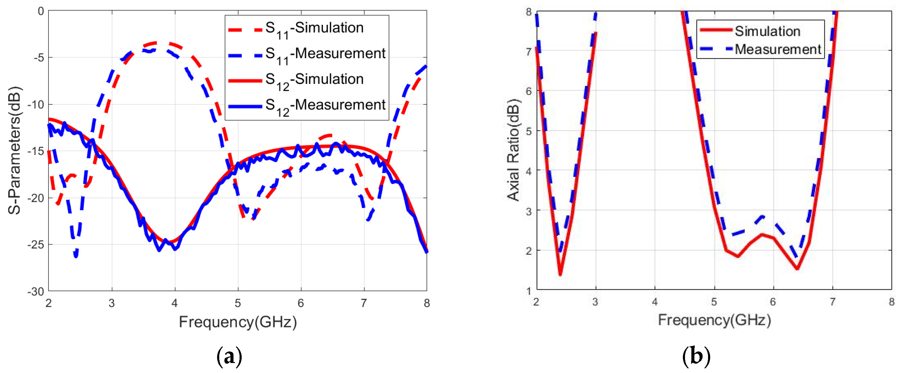
Figure 8a presents the simulated and measured S-parameters. The measured data are in good agreement with the simulated results. Experimentally, the proposed antenna achieves a 10 dB impedance bandwidth of 33.3% (2–2.8 GHz) and 50% (4.5–7.5 GHz), which effectively covers the two target frequency bands. The measured isolation between the two ports exceeds 10 dB, meeting the basic requirement for dual-port operation. This can effectively reduce mutual interference between the two ports. The slight discrepancy observed between the simulated and measured S-parameters is primarily attributed to height deviations introduced during the welding of SMA connectors.
Figure 8.
Simulated and measured results: (a) S-parameters. (b) Axial ratio.
Figure 8b gives the simulated and measured axial ratio results when port 1 is fed independently. The measured results agree well with the simulation data. The maximum axial ratio of the proposed antenna across 2.24–2.58 GHz and 5.1–6.6 GHz is 3 dB. The measured operating bandwidths (for 10 dB return loss and 3 dB axial ratio) are 14.1% and 25.64%, respectively. However, due to the influence of the SMA connectors’ welding, fabrication tolerances, and unavoidable perturbations from the test environment, the measured results are slightly different from the simulations.
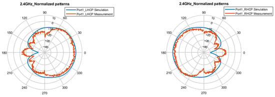
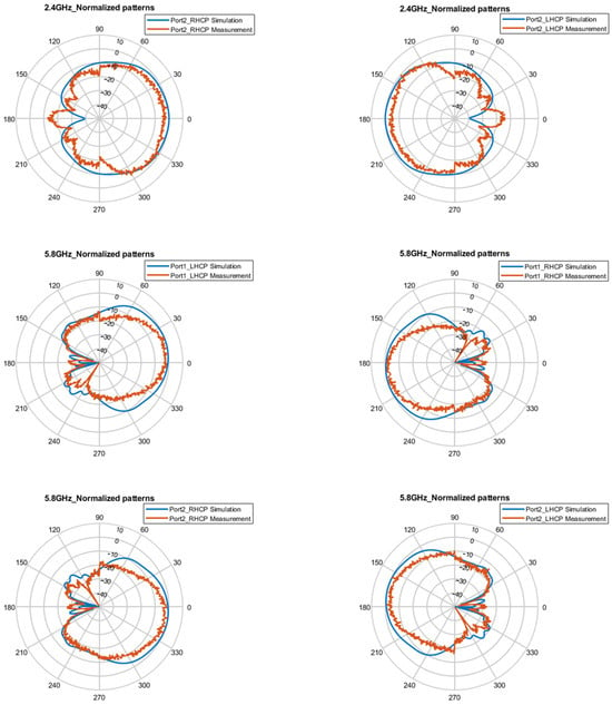
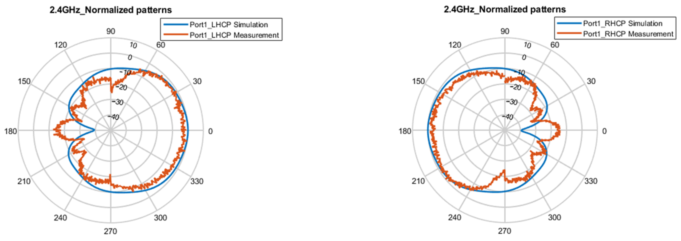
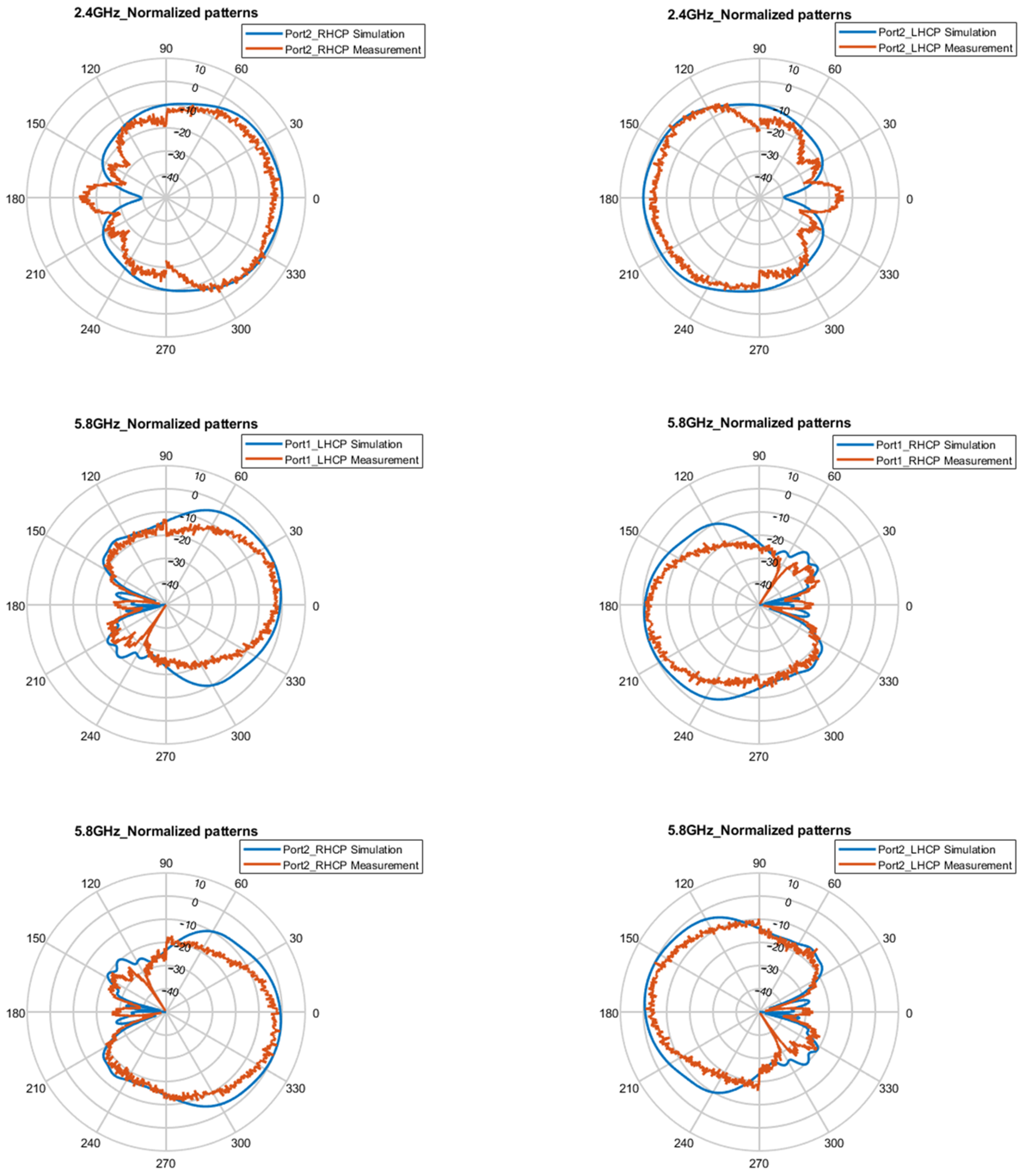
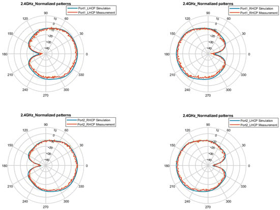
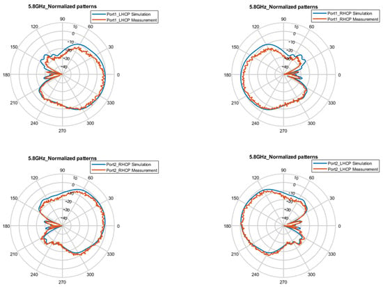
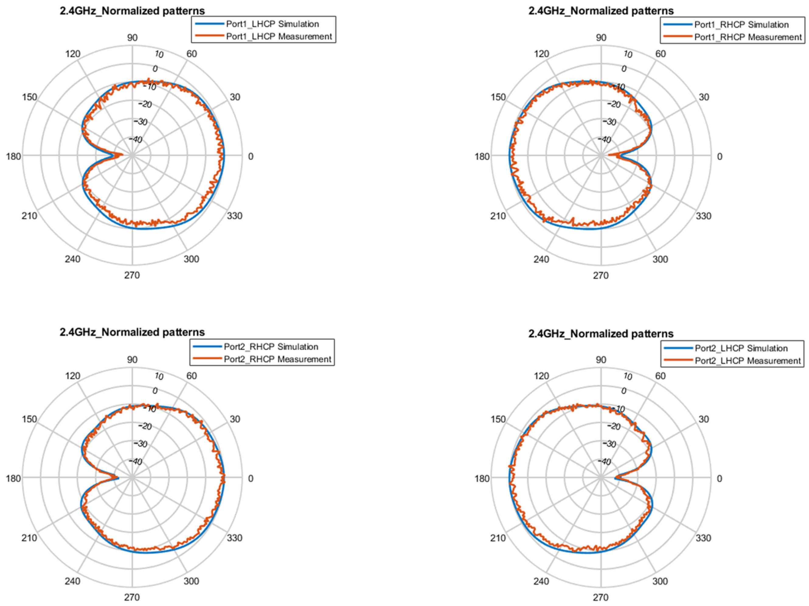
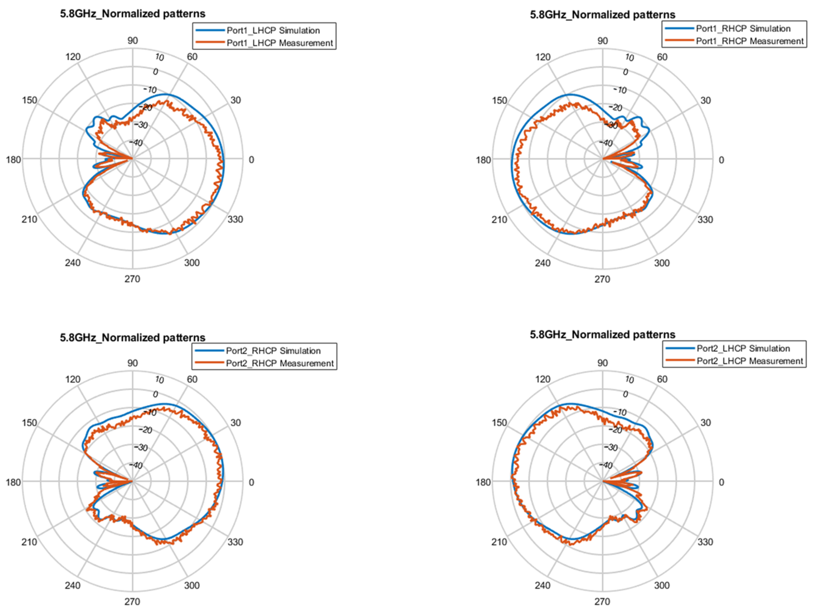
Figure 9 and Figure 10, respectively, present the simulated and measured CP normalized patterns of the E-plane and H-plane at 2.4 GHz and 5.8 GHz. When port 1 is fed independently, the proposed antenna realizes LHCP in the +z direction and RHCP in the −z direction at the two frequencies. When only port 2 is fed, the proposed antenna implements RHCP in the +z direction and LHCP in the −z direction at two frequency points. Bidirectional radiation characteristics are observed at 2.4 GHz and 5.8 GHz bands. The normalized pattern exhibits stable performance, which is generally consistent with the simulated results without significant distortion.
Figure 9.
Normalized patterns of E-plane for the CP states at 2.4 and 5.8 GHz.
Figure 10.
Normalized patterns of H-plane for the CP states at 2.4 and 5.8 GHz.
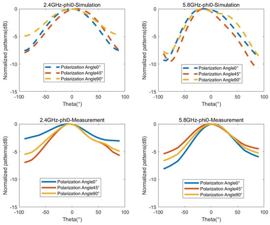
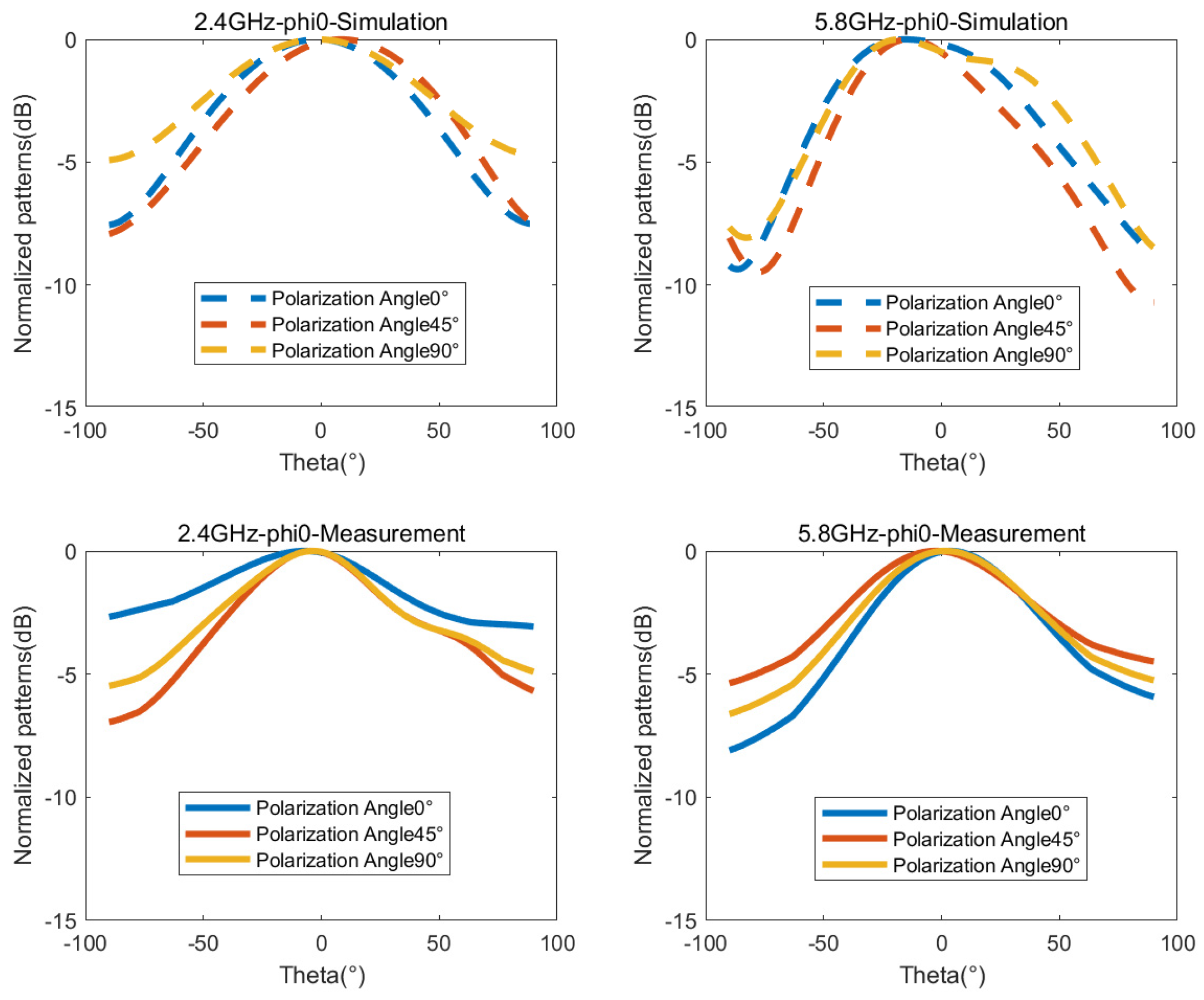
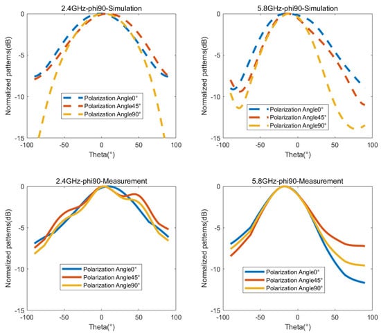
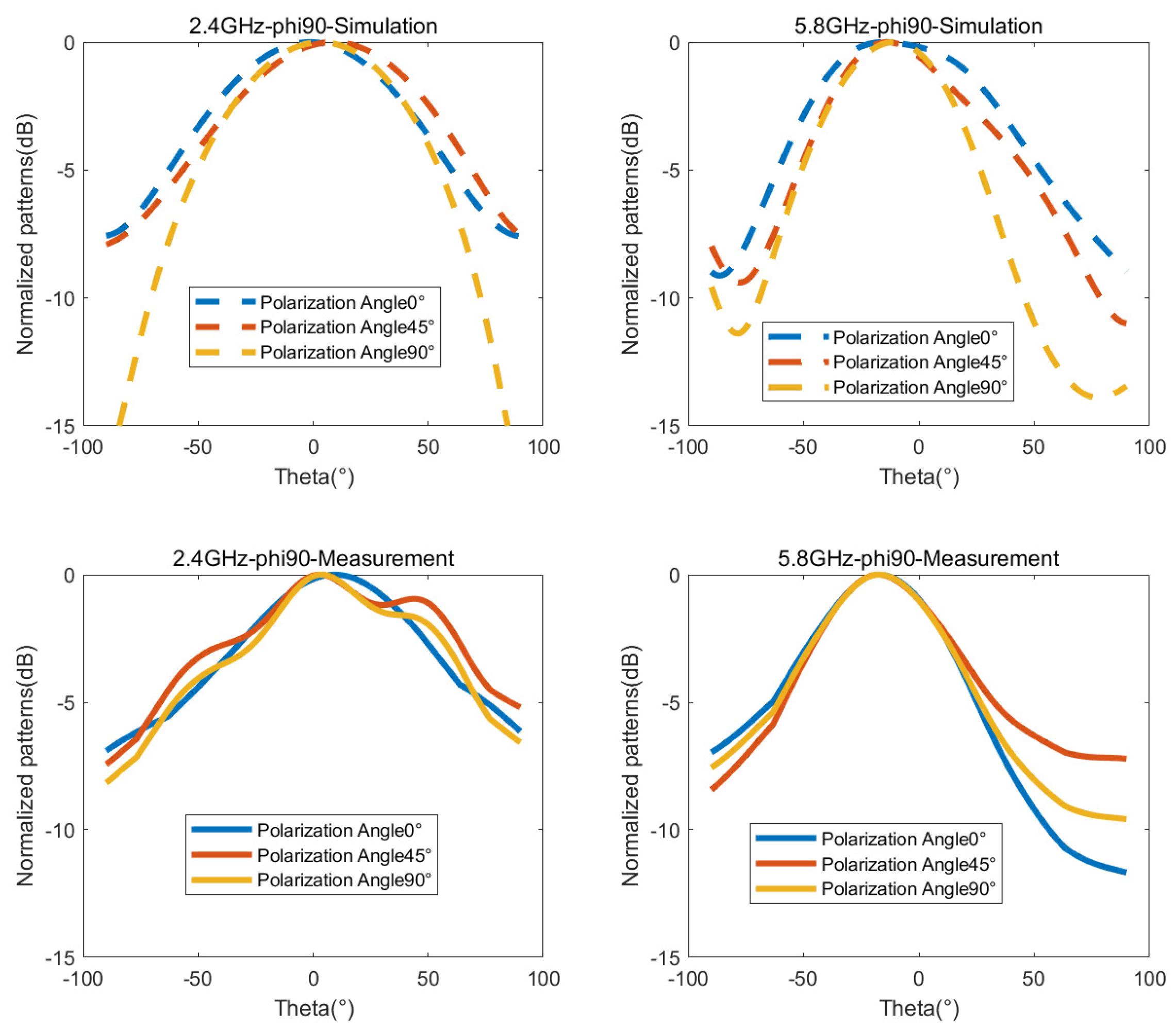
Figure 11 and Figure 12, respectively, show the simulated and measured radiation patterns of the E-plane and H-plane for the LP states at 2.4 GHz and 5.8 GHz. For verifying the theory of orthogonal dual-circular polarization synthesis, only the CP phase differences of 0°, 90°, and 180° are selected as representative cases. The discrepancies between measured and simulated results originate from the signal attenuation associated with the configuration of the controlled adjustable phase shifter and the test environment factors. Nevertheless, their overall trends exhibit general consistency, validating that the proposed antenna possesses reliable polarization performance for 0°, 45°, and 90° LP at 2.4 GHz and 5.8 GHz. These normalized patterns comprehensively demonstrate the effectiveness of the proposed antenna in generating arbitrary linear polarization waves by adjusting the phase difference.
Figure 11.
Normalized patterns of E-plane for the LP states at 2.4 and 5.8 GHz.
Figure 12.
Normalized patterns of H-plane for the LP states at 2.4 and 5.8 GHz.
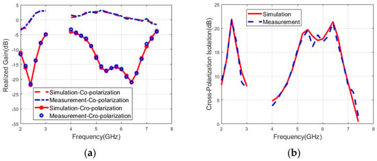
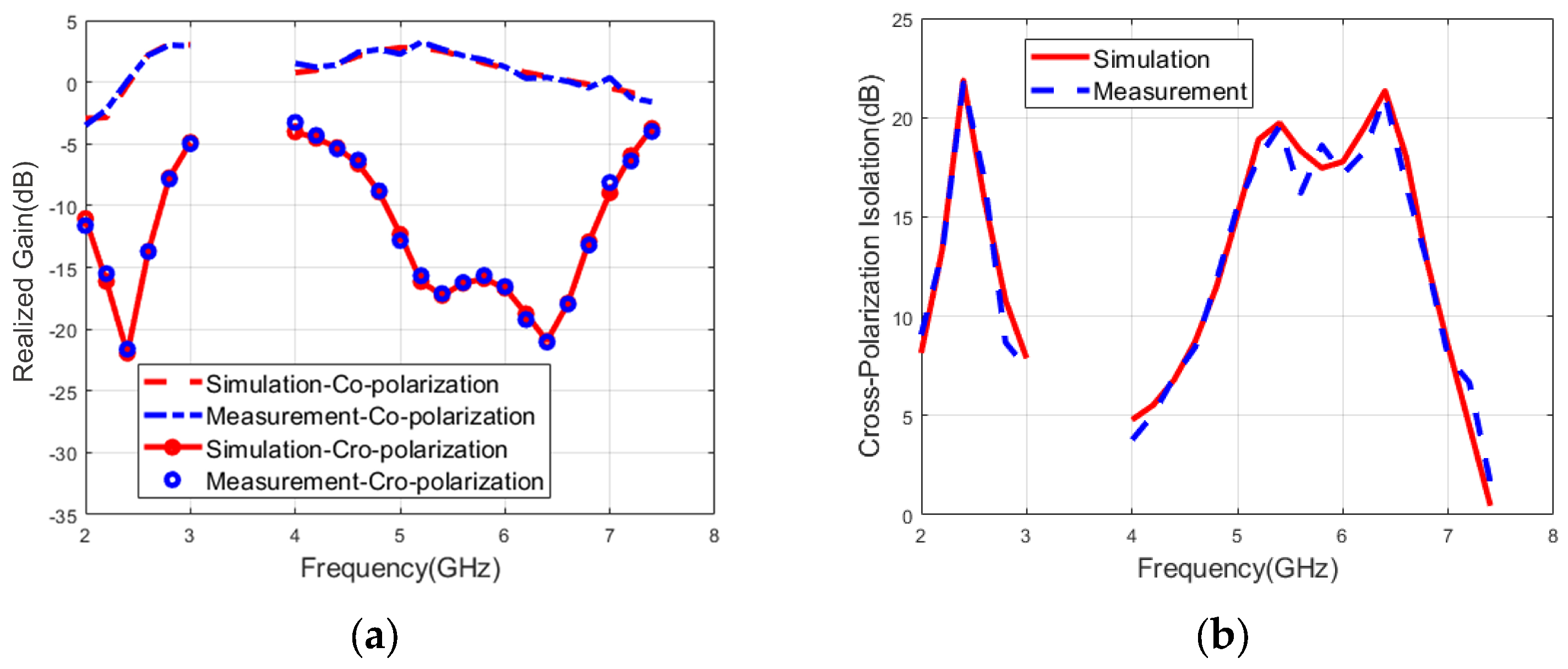
Figure 13 illustrates the measured and simulated results of realized gain and cross-polarization isolation when only port 1 is fed. The measured results are in good agreement with the simulations. The maximum CP gain reaches 3.1 dB, which is mainly related to the wideband dual-band structure and bidirectional radiation characteristics. The isolation degrees of CP cross-polarization within the 2.24–2.58 GHz and 5.1–6.6 GHz are above 15 dB and 17 dB, respectively.
Figure 13.
(a) Realized gain and (b) cross-polarization isolation of the CP state.
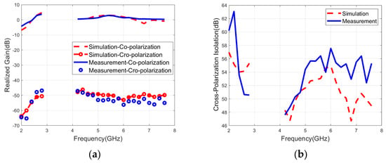
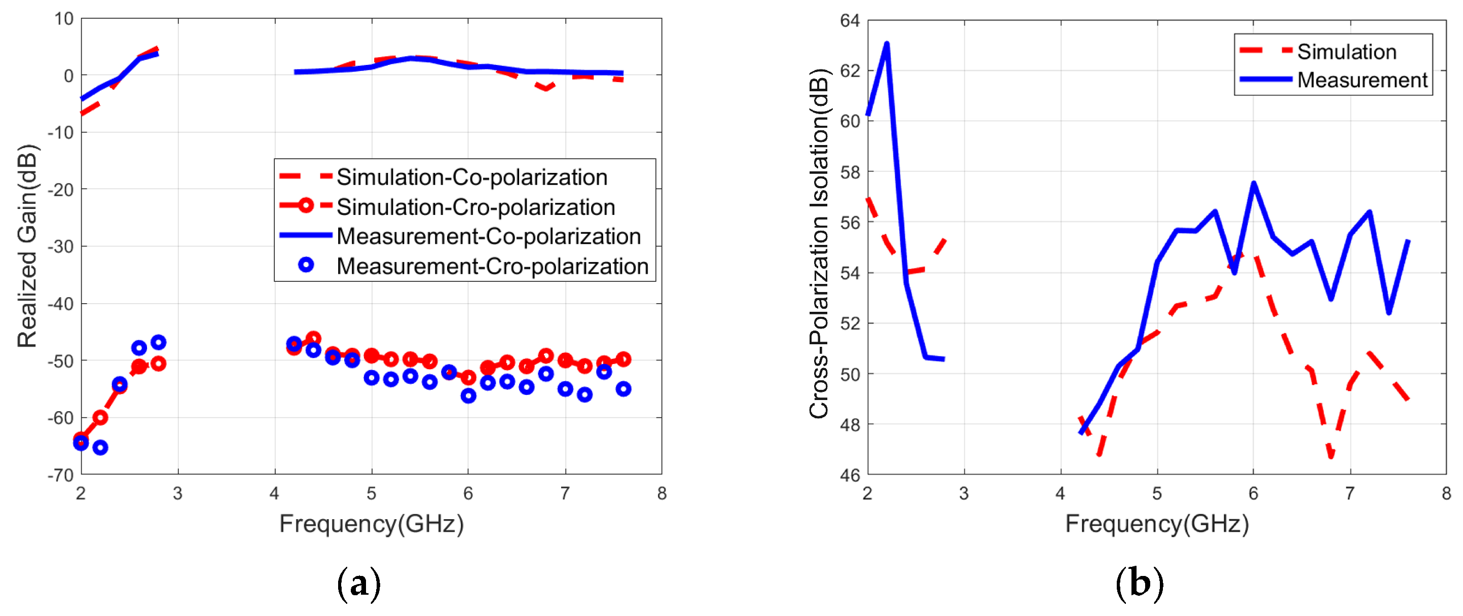
Figure 14 plots the realized gain and cross-polarization isolation of the proposed antenna when both ports are fed. The maximum LP gain is 4 dB, while the LP cross-polarization isolation across the 2–2.8 GHz and 4.5–7.5 GHz bands is all greater than 50 dB, indicating excellent polarization purity. This superior suppression ability means that the antenna effectively focuses energy on the main polarization, significantly reducing interference from cross-polarization components, which is crucial for applications requiring robust and reliable dual-band multi-polarized operation.
Figure 14.
(a) Realized gain and (b) cross-polarization isolation of the LP state.
Table 2 provides a comparison between the proposed antenna and previously reported dual-band multi-polarized microstrip antennas, considering implementation methods of dual bands, number of ports and layers, polarization modes, relative bandwidth, polarization isolation, high and low resonant frequency ratio, and profile. It should be noted that for the CP mode, the relative bandwidth refers to the bandwidth of the overlapped region between the impedance bandwidth (defined by a 10 dB return loss) and the 3 dB axial ratio bandwidth, and the same applies to the operating frequency.
Table 2.
Performance comparisons of dual-band multi-polarized microstrip antennas.
Compared to antennas in Table 2, the proposed antenna achieves a critical breakthrough in integrating comprehensive performance into a simplified structure. It simultaneously features full polarization, high frequency ratio, high polarization isolation, low profile, and arbitrary linear polarization angle, with distinct advantages in polarization modes, bandwidth, and profile. Unlike most existing antennas adopting multi-layer substrates, switch RFs, or complex slot structures for limited polarization states, the proposed single-layer antenna uniquely realizes full polarization across two bands. This simplifies fabrication and cuts costs. It balances a high frequency ratio (up to 2.42:1) and a high LP isolation (>50 dB) without complex switching or feeding networks, addressing the structure-complexity and performance-completeness challenge.
4. Conclusions
In this paper, a single-layer dual-band full-polarized annular-ring slot antenna is proposed. The proposed antenna adopts an orthogonal dual-circular polarization symmetrical structure design. Left-hand circular polarization, right-hand circular polarization, and arbitrary linear polarization across dual bands are achieved by controlling the feeding ports. The overlapped effective operating frequency band under all polarization modes reaches 340 MHz (2.4 GHz) and 1500 MHz (5.8 GHz). The proposed antenna exhibits characteristics such as dual-band, full polarization, high polarization isolation, arbitrary linear polarization angle, low profile, and bidirectional radiation, which offer an effective solution to critical challenges involving massive device access, spectrum resource reuse, arbitrary polarization transmission and reception, and polarization tracking and matching. The antenna is of great practical value for the urgent demands of modern multi-functional integrated systems, such as Wi-Fi 6, satellite navigation, and UAV measurement and control. Given that the application may be affected by requirements of the controlled adjustable phase shifter, fabrication tolerances, and cross-band scalability, enhancing gain is prioritized for future work. Metasurface technology, array integration, and phase gradient engineering are proposed to boost gain via beam focusing, advancing the applicability to the multi-functional systems [21].
Author Contributions
Conceptualization, X.W.; methodology, X.W. and H.Z.; software, X.W.; validation, X.W. and H.Z.; formal analysis, X.W.; investigation, X.W. and Y.B.; resources, M.Z. and C.Z.; data curation, X.W. and H.Z.; writing—original draft preparation, X.W. and H.Z.; writing—review and editing, X.W., H.Z., Y.B., Y.H., X.X., M.Z. and C.Z.; visualization, Y.B. and X.X.; supervision, C.Z. and Y.H.; project administration, Y.H. and M.Z.; funding acquisition, M.Z. and C.Z. All authors have read and agreed to the published version of the manuscript.
Funding
This research was funded by the Key Laboratory of Flight Techniques and Flight Safety, CAAC (FZ2022ZZ03), Sichuan Civil Aviation Flight Technology and Flight Safety Engineering Technology (GY2024-10C), Sichuan Provincial Engineering Research Center of Smart Operation and Maintenance of Civil Aviation Airports (JCZX 2024ZZ14), Fund Project for Basic Scientific Research Expenses of Central Universities (24CAFUC03020, 24CAFUC03022), Open Fund of Key Laboratory of Flight Techniques and Flight Safety, CAAC (F2024KF23E, F2024KF24E).
Data Availability Statement
The data supporting the findings of this study are available from the corresponding author upon reasonable request.
Conflicts of Interest
The authors declare no conflicts of interest.
References
- Zhang, K.; Jiang, Z.H.; Yue, T.; Zhang, Y.; Hong, W.; Werner, D.H. A compact dual-band triple-mode antenna with pattern and polarization diversities enabled by shielded mushroom structures. IEEE Trans. Antennas Propag. 2021, 69, 6229–6243. [Google Scholar] [CrossRef] [Scilit]
- Sun, W.; Li, Y.; Chang, L.; Li, H.; Qin, X.; Wang, H. Dual-band dual-polarized microstrip antenna array using double-layer gridded patches for 5G millimeter-wave applications. IEEE Trans. Antennas Propag. 2021, 69, 6489–6499. [Google Scholar] [CrossRef] [Scilit]
- Li, Y.; Zhao, Z.; Tang, Z.; Yin, Y. Differentially fed, dual-band dual-polarized filtering antenna with high selectivity for 5G sub-6 GHz base station applications. IEEE Trans. Antennas Propag. 2019, 68, 3231–3236. [Google Scholar] [CrossRef] [Scilit]
- Feng, B.; Li, L.; Cheng, J.C.; Sim, C.Y.D. A dual-band dual-polarized stacked microstrip antenna with high-isolation and band-notch characteristics for 5G microcell communications. IEEE Trans. Antennas Propag. 2019, 67, 4506–4516. [Google Scholar] [CrossRef] [Scilit]
- Fazal, D.; Khan, Q.U. Dual-band dual-polarized patch antenna using characteristic mode analysis. IEEE Trans. Antennas Propag. 2021, 70, 2271–2276. [Google Scholar] [CrossRef] [Scilit]
- Zhang, Y.; Zhang, X.Y.; Pan, Y.M. Compact single-and dual-band filtering patch antenna arrays using novel feeding scheme. IEEE Trans. Antennas Propag. 2017, 65, 4057–4066. [Google Scholar] [CrossRef] [Scilit]
- Zheng, Q.; Wang, J.; PourMohammadi, P.; Pang, X. Dual-band metasurface-based closely packed antennas by controlling surface wave propagation. IEEE Antennas Wirel. Propag. Lett. 2024, 23, 1633–1637. [Google Scholar] [CrossRef] [Scilit]
- Serup, D.E.; Pedersen, G.F.; Zhang, S. Dual-band shared aperture reflectarray and patch antenna array for S-and Ka-bands. IEEE Trans. Antennas Propag. 2021, 70, 2340–2345. [Google Scholar] [CrossRef] [Scilit]
- Sahoo, P.; Singhal, P.K.; Markam, K. Enhancing axial ratio bandwidth of dual band microstrip patch antenna for GSM application. IEEE Lat. Am. Trans. 2024, 22, 352–360. [Google Scholar] [CrossRef] [Scilit]
- Sahana, C.; Jayakumar, M. Dual-band circularly polarized annular ring patch antenna for GPS-aided GEO-augmented navigation receivers. IEEE Antennas Wirel. Propag. Lett. 2022, 21, 1737–1741. [Google Scholar]
- Samantaray, D.; Ghosh, S.K.; Bhattacharyya, S. Modified slotted patch antenna with metasurface as superstrate for dual-band applications. IEEE Antennas Wirel. Propag. Lett. 2022, 22, 109–113. [Google Scholar] [CrossRef] [Scilit]
- Cui, J.; Zhang, A.; Yan, S. A novel compact dual-band circular/linear polarization switchable slot annular antenna with filtering network. Int. J. RF Microw. Comput.-Aided Eng. 2021, 31, 22767. [Google Scholar] [CrossRef] [Scilit]
- Anantha, B.; Merugu, L.; Rao, P.S. A novel single feed frequency and polarization reconfigurable microstrip patch antenna. AEU-Int. J. Electron. Commun. 2017, 72, 8–16. [Google Scholar] [CrossRef] [Scilit]
- Le, H.D.; Ta, S.X. A Compact Dual-Band Dual-Polarized Antenna Using Non-Uniform Metasurface and Mushroom Structures for Wi-Fi 7 Applications. IEEE Antennas Wirel. Propag. Lett. 2025, 24, 3114–3118. [Google Scholar] [CrossRef] [Scilit]
- Ta, S.X.; Phung, T.T.; Nguyen, K.K.; Nguyen-Trong, N. Low-profile dual-band tripolarized antenna using monopolar slotted patch. IEEE Antennas Wirel. Propag. Lett. 2023, 22, 2925–2929. [Google Scholar] [CrossRef] [Scilit]
- Mao, C.X.; Jiang, Z.H.; Werner, D.H.; Gao, S.S.; Hong, W. Compact self-diplexing dual-band dual-sense circularly polarized array antenna with closely spaced operating frequencies. IEEE Trans. Antennas Propag. 2019, 67, 4617–4625. [Google Scholar] [CrossRef] [Scilit]
- Wang, X.; Zhou, H.; Wang, X.; Lei, X.; Hao, B.; Zhong, M.; Zhou, C. A Wideband Multi-Polarized Microstrip Antenna with High Polarization Isolation Based on Dual-Circular Polarization. Micromachines 2025, 16, 1209. [Google Scholar] [CrossRef] [Scilit]
- Huang, C.; Guo, C.J.; Yuan, Y.; Ding, J. Dual-band dual-sense high-gain circularly polarized metasurface antenna using characteristic mode analysis. IEEE Antennas Wirel. Propag. Lett. 2022, 22, 154–158. [Google Scholar] [CrossRef] [Scilit]
- Mao, C.X.; Werner, D.H.; Zhang, Y.; Zhang, X.Y. Compact dual-band dual-mode antenna with omni-/unidirectional radiation characteristics. IEEE Antennas Wirel. Propag. Lett. 2019, 18, 2657–2660. [Google Scholar] [CrossRef] [Scilit]
- Bharathi, A.; Lakshminarayana, M.; Rao, P.S. A quad-polarization and frequency reconfigurable square ring slot loaded microstrip patch antenna for WLAN applications. AEU-Int. J. Electron. Commun. 2017, 78, 15–23. [Google Scholar] [CrossRef] [Scilit]
- Li, J.; Jana, A.; Yuan, Y.; Zhang, K.; Burokur, S.N.; Genevet, P. Exploiting hidden singularity on the surface of the Poincaré sphere. Nat. Commun. 2025, 16, 5953. [Google Scholar] [CrossRef] [Scilit]

Disclaimer/Publisher’s Note: The statements, opinions and data contained in all publications are solely those of the individual author(s) and contributor(s) and not of MDPI and/or the editor(s). MDPI and/or the editor(s) disclaim responsibility for any injury to people or property resulting from any ideas, methods, instructions or products referred to in the content. |
© 2026 by the authors. Licensee MDPI, Basel, Switzerland. This article is an open access article distributed under the terms and conditions of the Creative Commons Attribution (CC BY) license.