


Abstract
Modern agriculture has to alleviate extremes in water demand and/or water waste. In this regard, this work showcases how soil moisture instruments can be combined with low-end microcontrollers, energy-efficient communication protocols, single-board computers, flow and pressure sensors, and purpose-built actuators to form a synergistic platform able to generate and study realistic irrigation scenarios. These scenarios, potentially emulating anomalies such as clogged emitters or pipe leaks with a satisfactory time granularity of a few minutes, provide valuable data that pave the way for the creation of intelligent models intercepting water misuse events and/or irrigation failures. The proposed system utilizes widely available, well-documented, low-cost components to form a functioning whole which is optimized for outdoor, low-power, low-maintenance and long-term operation and is accessible remotely via typical end-user devices. Two drip irrigation points were set up, each having a TEROS 12 and a TEROS 10 instrument placed at different depths, while a prototype water flow/pressure control and report system was developed. All modules sent data in real time, via LoRa, to a central node implemented using a Raspberry Pi for further processing and to make them widely available via common network infrastructures, also provisioning for remote scenario invocation. The system does not claim to achieve specific irrigation water savings, but it contributes to maintaining/increasing the benefits of modern irrigation practices (such as drip irrigation). This goal is served by emulating a wide variety of irrigation events and by gathering and studying the corresponding data. These multimodal data are collected at a frequency of a few minutes, reflecting key irrigation-specific parameters with an accuracy better than or equal to 3%. The exact steps for specific hardware and software component interoperation are clearly explained, allowing other teams of researchers and/or university educators worldwide to be inspired and benefit from platform replication.
1. Introduction
By 2050, our planet will be home to more than 9 billion people [1,2,3]. The majority of them will live in large urban centers [4]. By 2030, the demand for water will exceed the available quantity by 40% [5]. Furthermore, there is a need for food to be available for this larger and richer population [6]. This means that food production would have to increase by 70% in practice [7,8]. By 2050, farmers will need to double food production while using half the water they use today [9]. For this to become a reality, limited water resources must be used sustainably [10,11,12], and this poses a difficult challenge as the agricultural sector is the main water consumer on Earth, requiring nearly 70% of freshwater [1].
The way farmers use water resources can determine whether their crops thrive or struggle. In the 21st century, it is not effective to rely on traditional irrigation methods because these often waste water, consume more time, and do not always deliver the best results. Technological innovations in agriculture are being developed worldwide regarding the need for rational water management [13,14], aiming to alleviate concerns and ensuring that agricultural practices can become smarter, more precise, and thus a sustainable driver of growth for the economy. Among the pillars of this effort is the Internet of Things (IoT), an emerging technology reshaping the way we interact with the environment. IoT includes interconnected devices hosting sensors, radio modules, and actuators, forming a functioning whole that gathers, interchanges, and responds to information [15]. IoT is also becoming smarter in its decisions, assisted by the rapid progress in the area of Artificial Intelligence (AI) and the appealing affordability of related equipment, thus multiplying the benefits for irrigation improvement [16]. As AI rapidly invades almost all areas of science, it provisions for raising awareness of water scarcity, for preventing water overuse, and for accelerating the adoption of sustainable water practices, to save water, to reduce costs, and to optimize crop growth simultaneously [17]. Smart irrigation is the future of farming [18,19] and is expected to bring revolutionary changes in water conservation and sustainable agriculture.
Delving deeper into the subject, implementation of efficient irrigation systems such as drip irrigation or subsurface irrigation could save up to 25–50% of water compared to surface irrigation [20]. In particular, drip irrigation is a very efficient technique that delivers water slowly and close to the plant roots via pipes, tubes and emitters, drastically reducing water loss from evaporation and runoff. Furthermore, this method keeps foliage dry, avoids watering neighboring weed growth, prevents diseases, and provides optimal moisture for healthier, higher-yielding plants. Mainly in linear crops and tree crops, drip irrigation can save large amounts of water [21]. At the same time, energy is saved since drip irrigation can operate with low pressure levels, i.e., starting from 1 atm to 2 atm [22]. The fact that the feed pressure remains constant ensures that the irrigation device will deliver the correct volume of water to the crops being grown.
Rajak et al. [23] compared several types of sensors as IoT-enabled devices and their applicability for analysis, decision making, and further required actions on farms. Millan et al. [24] evaluated the performance of six moisture sensors (among them, TEROS 10 and 11) and provided calibration equations for a typical sandy soil used for strawberry production. TEROS 10 behaved similarly under both factory equation and corrected equation settings in a low-soil-moisture regime. Pereira et al. [25] assessed the performance of a smart IoT-enabled drip irrigation system which was designed by connecting an ESP32 microcontroller with four sensors measuring soil moisture, temperature, air humidity and water flow and interacting with the Blynk application, which is used to get irrigation data, water the plants and turn on and off the automatic watering feature. By using the Blynk dashboard, the automatic function and the manual opening of a solenoid valve were tested, and the performance of the whole system was considered successful.
Correa-Quiroz et al. [26] proposed an ESP32-based IoT system for intelligent drip irrigation and a climate monitoring system for greenhouses. They used predefined moisture thresholds to activate or deactivate the drip irrigation system based on the data. These data were collected by various sensors, such as DHT11 sensors for temperature and humidity, GUVA-S12SD for UV radiation, capacitive soil moisture sensors and HC-SR04 for water level measurement, and were transmitted by the ESP32 node to the cloud via Wi-Fi, with the information being presented in real time. Experimental results showed a 35% reduction in water consumption compared to traditional systems. Similarly, an STM32 microcontroller integrated with a LoRa module along with a sensor, charger, solar panel and battery has been used by Inayah et al. [27] in their research on irrigation scheduling for increasing the productivity of drip-irrigated Cilembu sweet potato. Their method led to a 45% increase in productivity and to 65% water savings, compared to conventional sprinkler systems. As the authors state, a complete irrigation system is provided (including sensing and acting components), which is also fluently evaluated in the field, something that is not always the case with innovative research works.
Rajasekaran et al. [28] developed a LoRa-based smart irrigation system by using a low-cost soil moisture sensor, LDR sensor, temperature sensor, three-phase voltage sensor, water flow sensor and current sensor. The whole IoT system was complemented by a neural network (NN) for irrigation decisions and by a fuzzy logic system. The researchers in [29] proposed a LoRa-based (LoRaWAN, in particular) Internet of Things smart irrigation control solution with a hybrid classifier (CNN-SVM) convolutional neural support vector machine scheme. The tracked soil measurements are delivered to the IoT cloud server for storage and analysis with machine learning algorithms thereon to follow the irrigation plan to be applied, potentially bypassing weekly irrigation demands, in conformity with soil states and the climate. Recently, the authors of [30] developed an AI-supported irrigation system (utilizing Long Short-Term Memory (LSTM) neural network structures and Arduino MEGA microcontroller nodes) that continuously monitors air and soil moisture levels, ensuring optimal irrigation conditions and instant adaptation to seasonal variations. Gaitan et al. [16] present a system that utilizes ESP32 nodes, collects critical parameters (e.g., temperature, humidity, and soil moisture), provides detailed information and advanced analytics for each device and area monitored, and, via OpenAI models, generates predictive recommendations. The data transmission is performed wirelessly via WebSocket to a central database.
Apart from the AI benefits, regarding communication technology concerns, LoRa appears to be the best alternative to Wi-Fi due to its capability for extended coverage, its low power consumption, and its operation in the no-license-needed Industrial, Scientific, and Medical (ISM) bands. Consequently, although Wi-Fi is the most frequently cited technology in scientific publications on IoT-based irrigation systems, LoRa follows, since researchers are trying to overcome the limitations of Wi-Fi concerning, e.g., its high power consumption and/or its limited transmission range, as pointed out by Abdelmoneim et al., 2025 [17]. In the wider context, several research works concentrate mostly on methodology and innovation priorities, and thus provide proof-of-concept-level implementation quality only. Consequently, posing fluent requirements for long-term operation under harsh agri-field conditions is often overlooked and left for future investigation [31]. This fact may signify connections that are prone to rust or disassemble (e.g., breadboards), no provision for efficient low-energy/sleep mode operation, box enclosures that degrade rapidly (e.g., by solar radiation or by humidity factors), and limited radio coverage. Similarly, interference problems and lack of encryption may further degrade sensor data delivery quality and pose cybersecurity concerns [32].
In addition, many researchers have focused their research on irrigation optimization methods based on physics-based or water balance models. Mao et al. [33] proposed a zone model predictive control approach that regulates soil moisture within an agronomically acceptable range using an asymmetric cost function, improving irrigation efficiency and robustness compared with traditional set-point-based control methods. Garcia et al. [34] proposed a discrete sliding mode controller for irrigation management that maintains soil moisture within a desired range under system uncertainties, achieving substantial water savings compared with time-based irrigation. Alla et al. [35] introduced a feedback control approach for irrigation optimization within a Richards equation framework, aiming to maximize root water uptake while minimizing irrigation input through dynamic boundary control. These model-based approaches combine real-time measurements with the physical behavior of the soil–plant–water system, making irrigation decisions less sensitive to degraded sensor data.
Data required for either advanced AI model training or more conventional hydrological formula processing should be of satisfactory quality and diverse enough at the same time. Unfortunately, the quality and quantity of the data provided in real conditions, by the currently used agricultural platforms, are subject to various intrinsic or exogenous factors (such as power losses, interference, climate extremes, instrument reinstallation changes and/or failures), resulting in deteriorated model performance and even in wrong irrigation decisions [36]. Therefore, providing a diverse set of controllable monitoring conditions assists greatly in revealing accurate relationships between data patterns and causal phenomena, often exploiting, detecting and/or anticipating data anomalies.
Although many IoT-enabled and AI-supported irrigation systems exist, most platforms operate under uncontrolled conditions, or strictly optimized conditions, highlighting the need for flexible experimental platforms allowing for further study and amelioration of irrigation process idiosyncrasies. In this context, this work innovates by focusing on how cost-effective and widely available hardware and software tools can be used to improve irrigation methods and to preserve water via characteristic big data generation and collection. More specifically, it contributes by:
- Proposing comprehensive methods defining the manner in which soil moisture instruments can be combined with low-end microcontrollers, energy-efficient communication protocols, single-board computers, flow and pressure sensors, and purpose-built actuators to emulate a diverse set of realistic irrigation event and malfunction scenarios, via user-defined scripts. Irrigation actions, potentially including anomalies (such as clogged emitters or water pipe leaks), are replicated with a satisfactory time granularity (of the order of a few minutes).
- Forming a cost-effective ecosystem to monitor and to collect a wide set of multimodal irrigation-sensitive data, related to and reflecting the impact of the aforementioned events being emulated. These data are collected at a frequency of a few minutes, reflecting key irrigation-specific parameters with an accuracy better than or equal to 3%. The interoperating elements and methods can be used to support smart watering action characterization and/or scheduling, via minor software upgrades.
- Proposing an exact roadmap indicating directions in which these data can be used to develop techniques for early detection of water misuse cases and/or potential irrigation failures and, last but not least, for invoking optimal precision irrigation actions, thus paving the way for more rational use of freshwater.
- Providing the necessary modularity and analysis for combining the discussed methodology with alternative physics-based or water balance models to enhance their effectiveness and robustness, as it can ensure the maintenance of desired soil moisture levels within a specific region of the root zone.
- Shedding light on several realistic design, implementation, installation and maintenance challenges being tackled, which are often omitted from description in this field. Specific provisions have been made in order to define all the necessary integration steps toward a functioning whole and to provide fluent guidance so that other teams of researchers and/or university students and educators can be inspired by and/or benefit from flawless platform replication.
2. Materials and Methods
2.1. Testbed Deployment Specifications
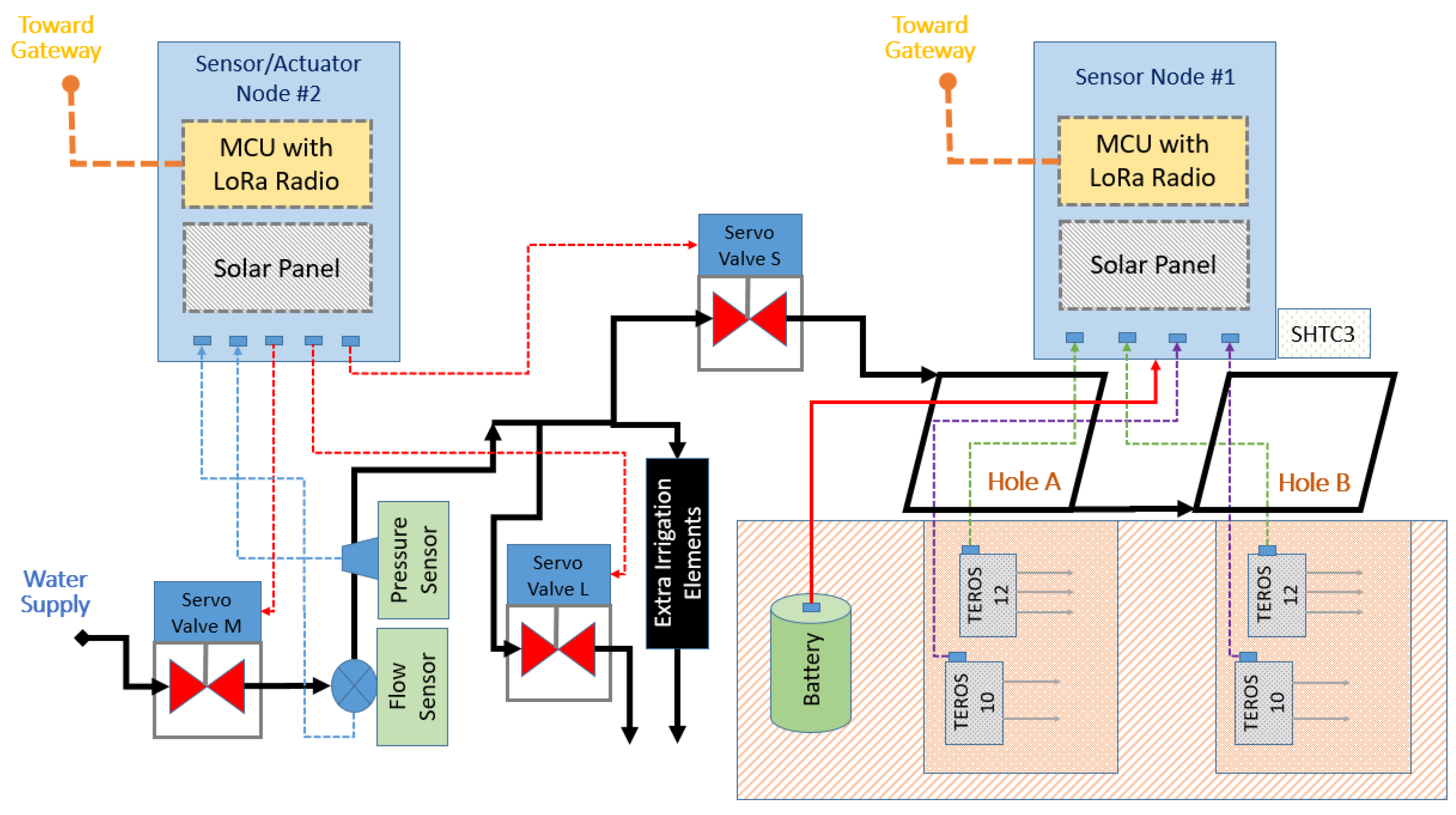
The proposed equipment deployment strategy in the agricultural field to support the irrigation scenario emulation and monitoring process is depicted in detail in Figure 1.
Figure 1.
Detailed deployment plan of the irrigation event emulation and monitoring equipment in the agricultural field.
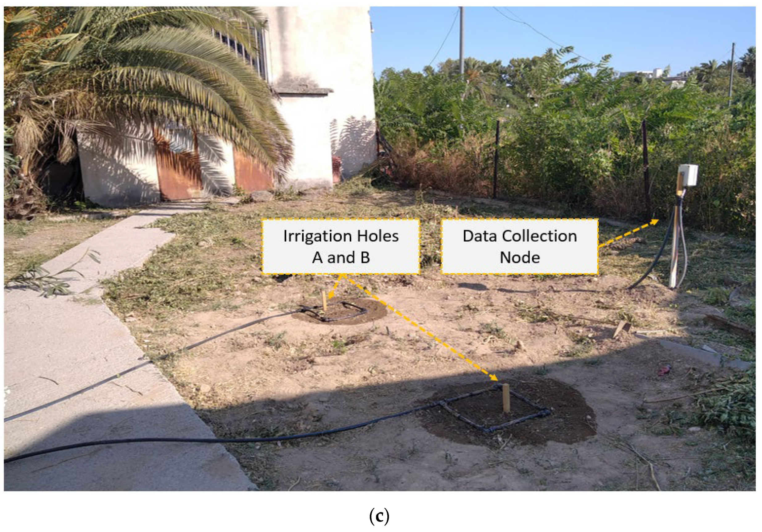
According to this description, two irrigation points (i.e., dugouts), namely A and B, were set up, each with a TEROS 12 and a TEROS 10 instrument placed at different depths, while a prototype water flow/pressure report and control system was developed. The locations of interest, A and B, were drip-irrigated via pipes forming two rectangles, each embracing areas A and B. The two pairs of TEROS 12 and TEROS 10 sensors were connected via cables with a specifically designed data aggregation and delivery node unit, placed nearby, according to the specifications described in our previous work [31], supported by a LoRa32u4 (DIYmall, Shenzhen, China) microcontroller unit (MCU). It should be mentioned that the bottom part of the box enclosure of the main node hosted an SHTC3 (made by Sensirion, Yokohama, Japan) digital air humidity and temperature sensor, providing complementary reference data against the below-ground measurements. The SHTC3 module has superior performance characteristics compared to its competitors, having ±2 RH air humidity and ±0.2 °C air temperature accuracy.
To transform irrigation decisions into actions and to emulate/identify irrigation anomalies (such as broken pipes, low water pressure, clogged emitters), in conjunction with the soil moisture data of points A and B, the water amount flowing into the pipe system had to be adjusted and thus a custom valve system had to be introduced. Furthermore, to accurately capture and study the behavior of the proposed experimental irrigation arrangement, we presupposed additional metering of the total water flow and the pressure inside the piping system. All these requirements justified the design and implementation of a second node, placed near the main water supply, in the agri-field. This second node followed the design and implementation principles of the node collecting the data from positions A and B.
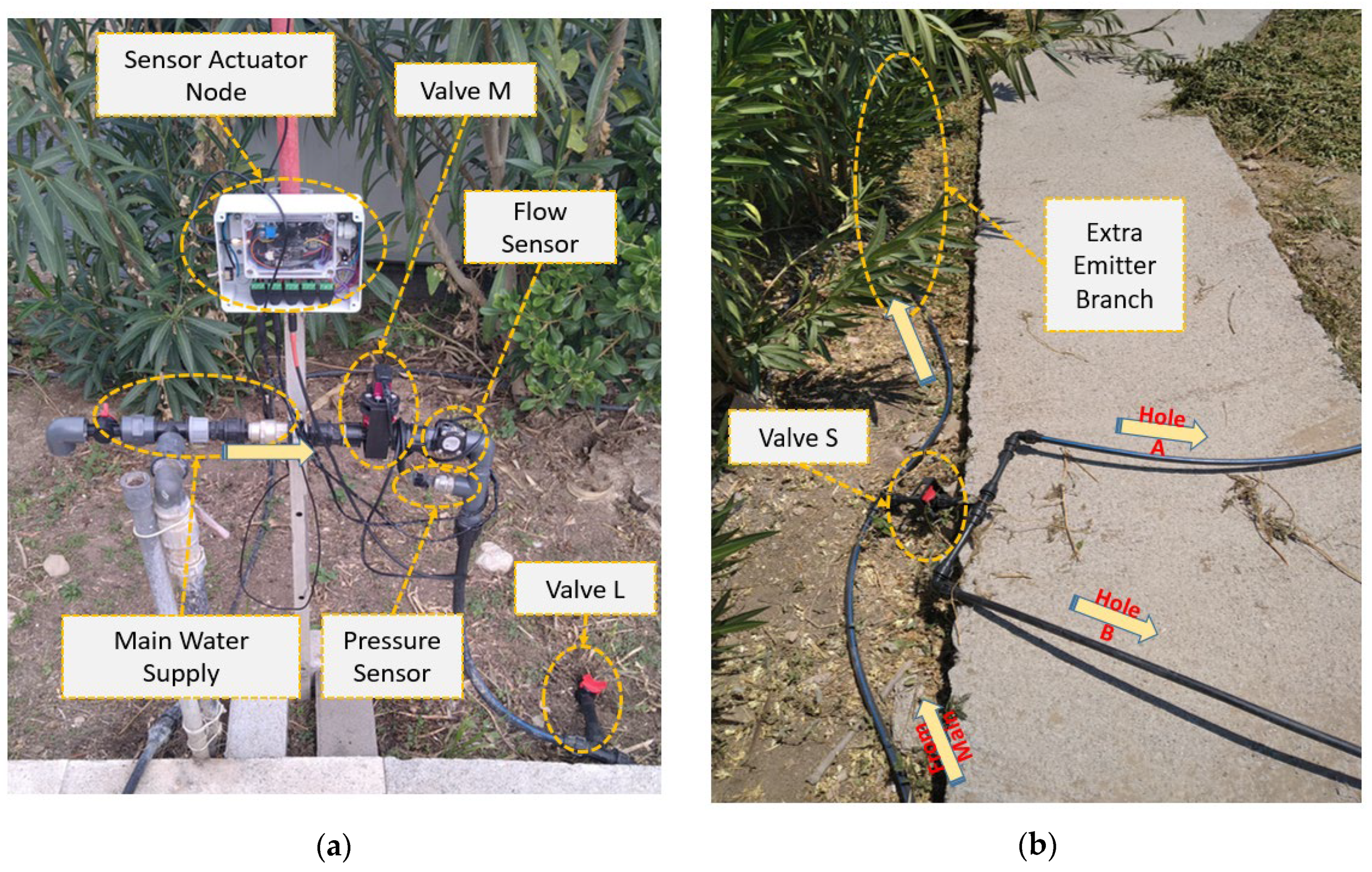
More specifically, provision was made for three automatic servo-assisted valves: one for regulating the main water supply (Valve M, in Figure 1), a second next to it for emulating pipe leak events (Valve L, in Figure 1), and a third one to emulate drip irrigation emitter stenosis events (Valve S, in Figure 1), placed right before points A and B. The latter servo-controlled stenosis valve (Valve S, in Figure 1) was utilized for isolating locations A and B from the rest of the drip irrigation system, in order to emulate the case where some of the emitters malfunction, providing less-than-necessary water to the plants. Indeed, in real systems, clogged drip irrigation emitters constitute a frequent problem (usually due to mineral deposits, algae, bacteria, or dirt) that may lead to uneven plant watering and to inadequate plant growth.
It should be noted that the entire pipe system had an extra branch with irrigation emitters, as shown in Figure 1, delivering water to a neighboring area, yet not close enough to points A and B, so as not to interfere with the moisture levels therein. This arrangement was necessary to create a total water flow that would be high enough to fall within the measuring range of the typical flow sensor (i.e., a YF-S201, ½-inch model, made by Haitronic, Hongkong, China) connected to the main water supply point (i.e., above 1 L/min). This sensor was generating pulses whose frequency was proportional to the amount of water passing through it. The liquid pressure sensor (i.e., a YD6080 model, made by YD WZYDDZ, Wenzhou, China) was installed in series with the flow sensor to monitor the pressure of the water supply to the irrigation pipes and generated analog voltage signal proportional to the pressure of water inside them.
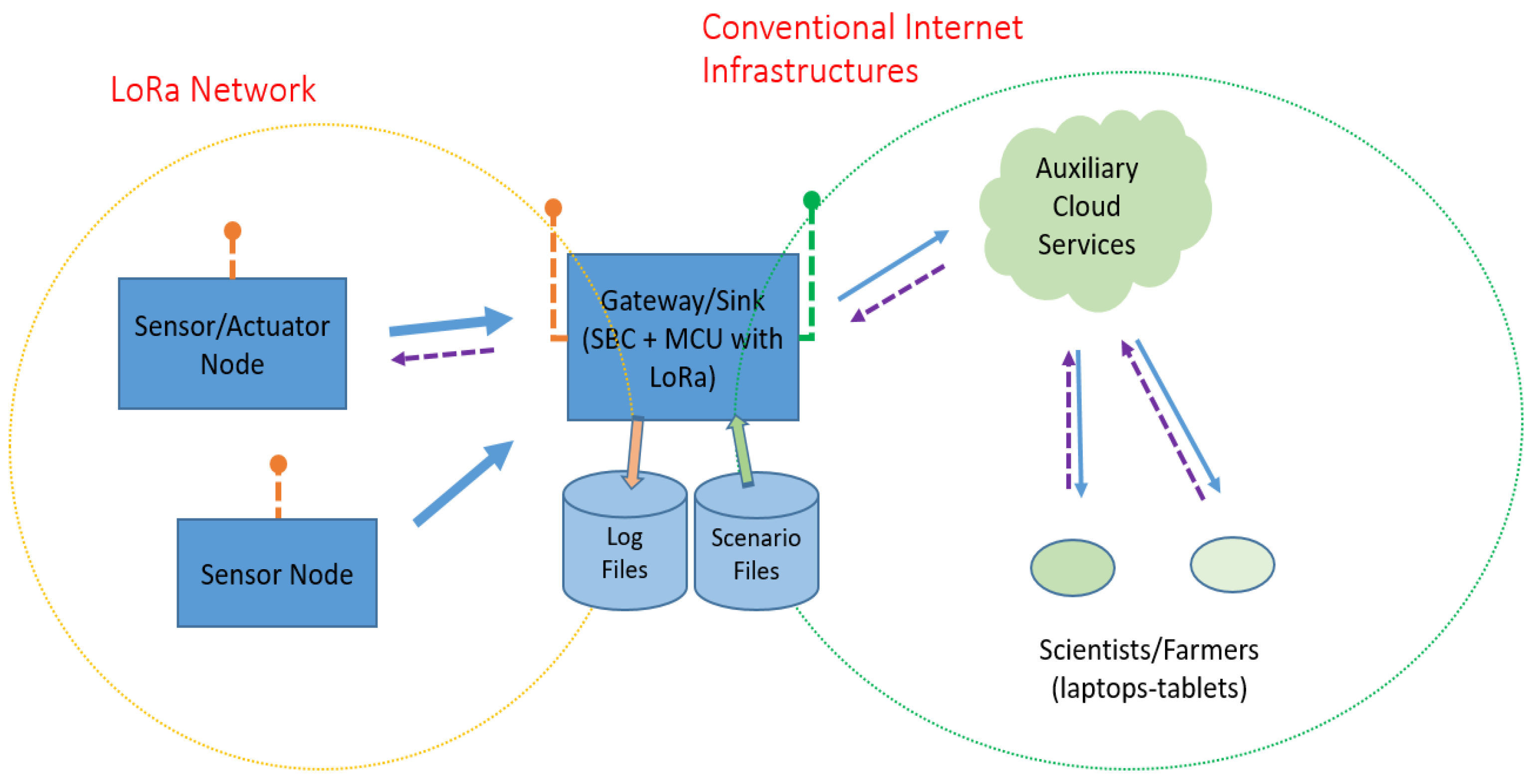
The two participating nodes sent data in real time, via LoRa, to a sink/gateway node implemented using a Raspberry Pi (RPi) single board computer (SBC), made by Raspberry Pi Foundation, Cambridge, UK, for further processing and storage, to make them widely available via a common network infrastructure, and, last but not least, for remotely scheduling the irrigation event emulation scenarios. The overall network infrastructure required to support the irrigation event emulation and monitoring process from the cloud site is depicted in Figure 2.
Figure 2.
The overall network infrastructure to support the irrigation event emulation and monitoring process. The solid-line arrows correspond to the irrigation data sensing flow, while the dashed-line arrows indicate irrigation action and monitoring (i.e., user-triggered) commands.
After briefly presenting the specifications of functions for a fluently working irrigation event emulation and monitoring platform, the following subsections provide analytic information on the steps required to integrate it.
2.2. The Key Measuring Components
One of the key measuring components is the TEROS 12 instrument. This device is a capacitance-based soil moisture sensor produced by Meter Group, Pullman, WA, USA. According to its manual [37], the TEROS12 sensor measures volumetric water in a range from 0 to 0.70 m3 m−3, its accuracy is reported to be ±3% in mineral soils that have solution electrical conductivity EC < 8 dS/m with standard factory calibration, and it can operate at temperatures ranging from −40 to 60 °C with a resolution of 0.1 °C and a measurement accuracy of ±1 °C. The sensor consists of three stainless steel needles 5.5 cm long, an epoxy body and a ferrite core. The operation frequency is 70 MHz, and it also measures soil temperature through a thermistor in the center needle. The measurements of TEROS 12 are provided via a digital interface supporting either the simpler serial (DDI) data format or the more complex SDI-12 data protocol. The device is compatible with 3.3 V logic, and it is also 5 V tolerant, while a voltage of 4 to 15 V DC should be supplied for it to function properly. The power consumption of TEROS 12 ranges from 3.0 mA to 16.0 mA, with a typical value close to 3.6 mA. The sensor output raw values are transformed to VWC (volumetric water content) and to apparent dielectric permittivity by the following calibration equations provided by the manufacturer:
θ (m3 m−3) = 3.879 × 10⁻⁴ × RAW − 0.6956
εa = (2.887 × 10⁻⁹ × RAW3 − 2.080 × 10⁻⁵ × RAW2 + 5.276 × 10⁻² × RAW − 43.39)2
The other key measuring component is the TEROS 10 capacitance-based instrument [38]. This sensor is the precedent model of TEROS 12 from the manufacturer Meter Group and estimates VWC indirectly by using an electromagnetic field to measure apparent dielectric permittivity. The two stainless steel needles of TEROS 10 are 5.5 and 5.1 cm long, and they effortlessly incorporate into any type of soil. The apparent dielectric permittivity (ea) of the surrounding medium is measured by the TEROS 10 sensor using an electromagnetic field. A 70 MHz oscillating wave is supplied by the sensor to the sensor needles, which charge in accordance with the material’s dielectric. The dielectric and VWC of the substrate are proportional to the charge time. Based on the substrate’s dielectric permittivity, the TEROS 10 microcontroller calculates the charge time and outputs a raw result. The raw values are then transformed to VWC by the following generic calibration equation provided by the manufacturer specific to mineral soils:
θ (cm3/cm3) = 4.824 × 10⁻¹⁰ × mV3 − 2.278 × 10⁻⁶ × mV2 + 3.898 × 10⁻³ × mV − 2.154
The raw values are also used to determine apparent dielectric permittivity using the following factory-calibrated equation:
ε = 1.054 × 10⁻¹ × e2.827 × 0.001 × mV
According to its manual [38], the TEROS 10 sensor measures volumetric water in a range from 0 to 0.64 m3 m−3, the accuracy is reported to be ±0.03 m3/m3 in mineral soils that have solution electrical conductivity EC < 8 dS/m, while it is ±0.05 m3/m3 in soilless media that have a solution EC < 8 dS/m with standard factory calibration, and its operating temperature range is from −40 to 60 °C. TEROS 10’s analog output signal has a voltage range of roughly 1000 to 2500 mV. This device has a nominal power consumption of about 12.0 mA and requires DC voltage between 3.0 V and 15.0 V to function correctly. The sensor is a low-cost device, easy to use, and compatible with the majority of data logging systems.
It should be noted that these are widely used instruments, and thus, apart from the equations provided by the manufacturer, several researchers [39,40,41] recommend improved calibration equations specific to the soil type or to other porous materials and for various salinity levels, for both sensors of the TEROS family. In this study, both soil-specific calibration equations and the manufacturer’s ones were applied for TEROS 10 and TEROS 12 sensors [39,41]. However, the soil moisture values reported are based on the manufacturer’s calibration equation, because the differences in moisture values obtained by both calibration equations were very small (±3%).
In a complementary manner, the meticulous measurement of water flow and pressure supplied to the irrigation system is critical for capturing and characterizing its behavior. The YD6080 non-corrosive liquid pressure sensor utilized exhibits a typical Full-Scale Output (FSO) accuracy of ±1.5%, which is a very satisfactory quantity. This sensing module is capable of measuring up to 1.2 MPa (or 12 bar) and thus suitable for the deployment of the aforementioned irrigation platform, which is expected to experience water pressure values close to 5–6 bar at maximum. According to its manufacturer, the YD6080 provides an analog output that varies from 10% to 90% of the supply voltage (Vcc) and is directly proportional to the measured pressure. Consequently, the 12 bar input is translated to 0.9∙Vcc volts to its output. This behavior can be easily modeled by the software of a low-end microcontroller. The YF-S201 flow sensor, is not a very accurate unit, with a typical uncertainty of 10% depending on various factors, like the temperature and the viscosity of the liquid passing through it, the expected flow range and its orientation, the diameter of the pipes it is connected to, and various manufacturing deviations. To improve its performance, the YF-S201 sensor was calibrated via the volumetric method, according to which the number of pulses and the corresponding time interval were counted via an Arduino microcontroller, in order for a certain water quantity (i.e., one liter) to pass via the piping including the sensor. In parallel, the flow was adjusted to match the average value characterizing the specific experimental deployment, i.e., close to 50 mL/s (or 3 L/min). Via this method, the coefficient expressing the number of milliliters passing through the pipe per pulse was more accurately determined, thus leading to an improved accuracy of ±3%. Both pressure and flow sensors, although rated as 5 V units, worked equally well with the 3.3 V supply voltage which was provided by the low-power microcontroller supporting the nodes. It is apparent that more accurate (and consequently costly) units should have been used, but, as irrigation irregularities are expressed relatively as a percentage of the normal/typical flow values, the significance of the specific sensor selection’s precision remains of limited importance.
2.3. Equipment Deployment Details
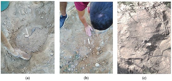
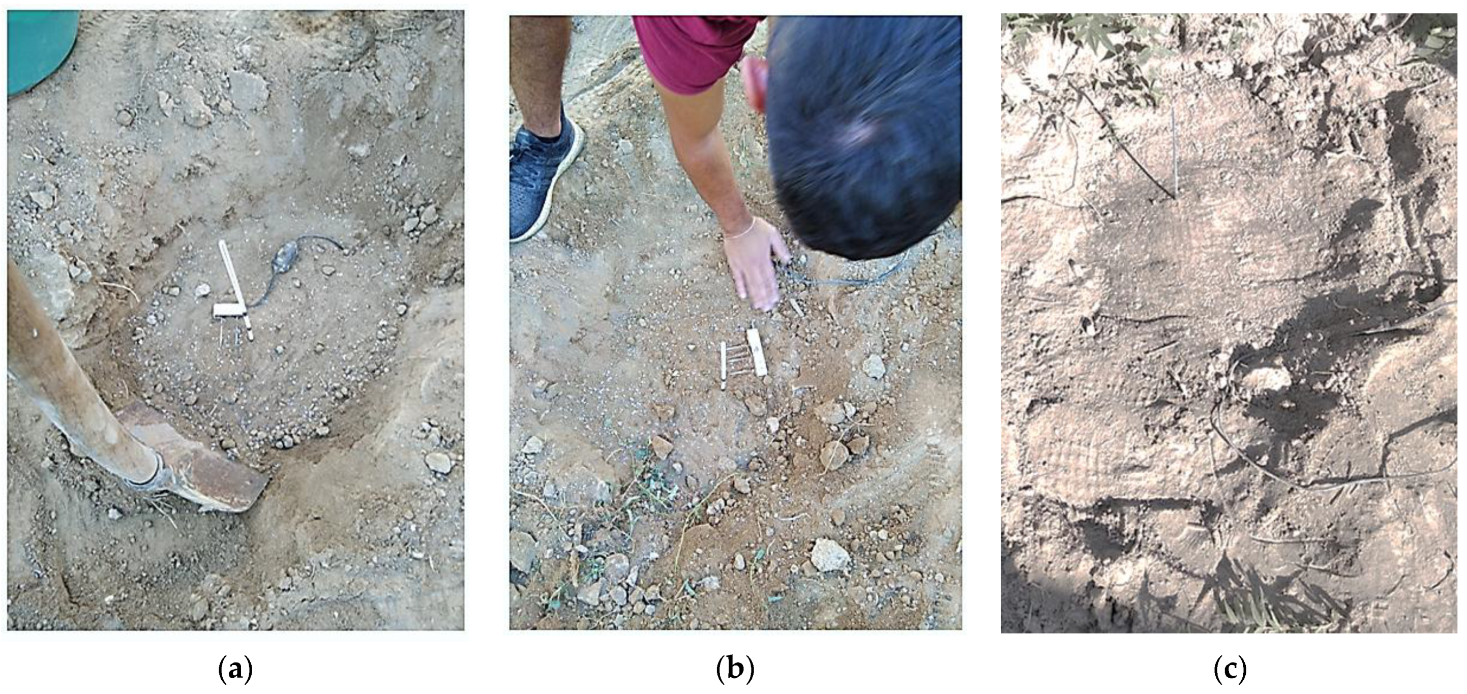
The irrigation emulation experiments took place at the campus of the university. Monitoring the environment was crucial to ensure that the procedure was operating as intended. Open-field experiments are of great interest as they simulate real environmental conditions. The experimental system was tested across all weather changes. Two small trenches were dug at a distance of two meters from each other, and a TEROS 12 unit was placed horizontally at a depth of 8 cm; meanwhile, a TEROS 10 unit was placed at a depth of 16 cm in each dugout/hole. The devices were covered meticulously by soil. Great emphasis was placed on the proper installation of all the sensors in order to avoid air gaps. Around the sensor–soil contact area, slight and careful compaction took place. The overall preparation stages are given in Figure 3a–c. The soil surrounding the places where the instruments were installed was nearly of the same type. In this way, two irrigation points, namely A and B, were created, allowing the periodic collection of real-time soil moisture data, in a manner that will become more apparent via the following description.
Figure 3.
Installing sensing equipment inside the irrigation holes: (a) placing a TEROS 10 instrument at 16 cm below ground level; (b) placing a TEROS 12 instrument at 8 cm below ground level; (c) filling the dugout completely with soil and compacting it.
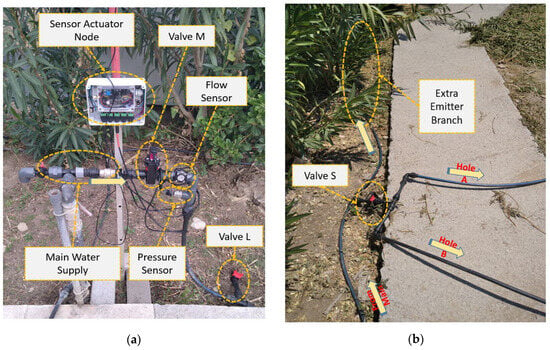
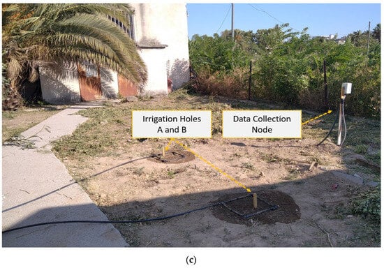
Figure 4a–c depict the actual deployment of the irrigation event emulation equipment in the agricultural field, close to holes A and B, hosting the soil sensors. In greater detail, Figure 4a depicts the node intercepting the total water flow and pressure and controlling the three irrigation valves (with its front protection cover intentionally open). Figure 4b illustrates the irrigation junction separating the irrigation emitters in different groups and the valve emulating emitter stenosis per hole, A and B. Figure 4c shows the irrigation pipes per hole, A and B, and the paired soil data harvesting sensor node.
Figure 4.
Actual deployment of the irrigation event emulation equipment in the agricultural field: (a) node intercepting the total water flow and pressure and controlling the three irrigation valves (with its front protection cover intentionally open); (b) irrigation junction separating the irrigation emitters in different groups and the valve emulating emitter stenosis per hole, A and B; (c) irrigation pipes per hole, A and B, and the corresponding soil monitoring equipment.
Most irrigation-specific parameters are collected at a frequency of 12 samples per hour (i.e., every 5 min). This adjustable interval is short enough to accurately capture the dynamic behavior of the irrigation process and adequately long so that the data collection nodes can function without requiring frequent battery replacement. In greater detail, the in situ sensor data collection unit could intercept the signals from two digital soil moisture instruments (i.e., the TEROS 12 units), via the DDI protocol method, and two analog soil moisture instruments (i.e., the TEROS 10 units), via the built-in ADC module. A dedicated bi-directional multiplexer was utilized for data collection and power cycling of the four instruments, in the following sequence: TEROS 12 A, TEROS 12 B, TEROS 10 A, and TEROS 10 B. All measurements were collected and transmitted via LoRa in less than one second, while after this activity period, the unit was automatically set to sleep mode for almost 5 min before waking up again (thus achieving the target sampling rate of 12 samples per hour). The whole system was powered by an 18,650 battery of 2500 mAh capacity, placed under the soil to avoid temperature extremes and improve longevity. An auxiliary 0.5 W solar panel was also included in the aforementioned unit, to practically eliminate the need for manual periodic battery charging. The main data collection and delivery system was hosted inside an IP65 box placed 1 m above the surface of the ground and equipped with a 5 dBm omnidirectional LoRa antenna for fluent data transmission. The node had the SHTC3 atmospheric humidity and temperature sensor, fixed inside a dedicated small 3D-printed protecting enclosure, in its bottom part.
The rectangular pipe formations embracing areas A and B had four drip irrigation emitters each. Each emitter was rated approximately 6 lt/h. The pipe system was dimensioned to have another 24 emitters for delivering water to the neighboring area described above, thus resulting in an easily measurable aggregate flow range. As already mentioned, a servo-controlled stenosis valve separated the emitters of holes A and B from the rest of the emitters. It is also worth noting that, in the area in which the experiments were performed, the water supply pressure exhibited strong pressure variation and a pressure limiting valve was installed to avoid values exceeding the 4 bar limit, thus alleviating the potentially damaging water hammering effect.
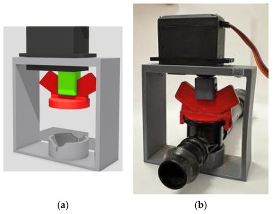
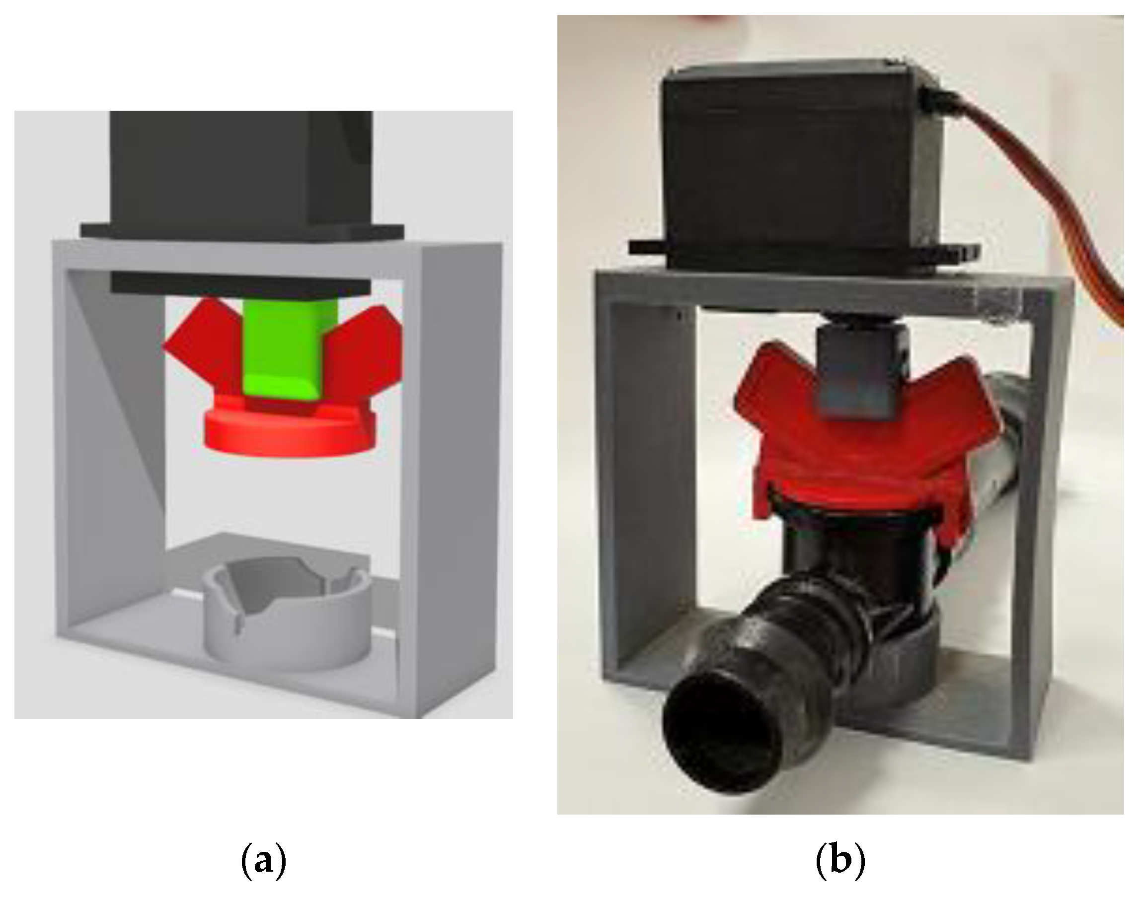
It is worth noting that, referring to the in situ installation, the automatic servo-assisted irrigation actuators utilized cheap fluid valves made of plastic that were modified to progressively open and close via dedicated angle servomotors. This adaptation of the servomotors required the 3D design and printing of custom parts, namely a plastic frame embracing the initial valve and hosting the servo (Figure 5a). Laboratory experiments, performed with brand-new valves, proved that a typical servo could produce enough torque to rotate the valve directly coupling the servomotor output to the valve handle (Figure 5b).
Figure 5.
The initial 3D-printed attachment to a typical plastic valve to convert it to a servo-assisted unit: (a) 3D design; (b) 3D-printed implementation with PLA and a direct link between the servo and the valve axes.
Consequently, the first 0–90-degree rotational movement range of the servomotor was translated to 0–90-degree movement of the actuation axis of the plastic valve. The prototype components were initially printed in polylactic acid (PLA), selected for its ease and its fast speed of printing. These initial arrangements had to be reconsidered, as will be explained in Section 3.2.
The second node controlling the valves and providing the aggregate flow and pressure data was hosted inside an IP65 box as well, exactly like the node capturing the soil moisture data, but it was equipped with stronger batteries and electronic circuits to efficiently drive the servomotors of the valves, one by one, whenever necessary. Consequently, this node included a step-up DC-DC voltage converter to generate 6 V from the (now two) 18,650 batteries, plus a microcontroller-activated electronic switch to provide power to the servomotors only when absolutely necessary, i.e., for altering the corresponding valve position. This node, apart from reporting flow and pressure data every 1 min, was able to accept valve open and close commands to a certain aperture level, utilizing a LoRa link with the Raspberry Pi-assisted sink/gateway central node.
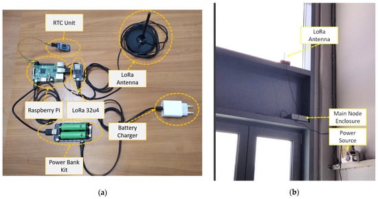
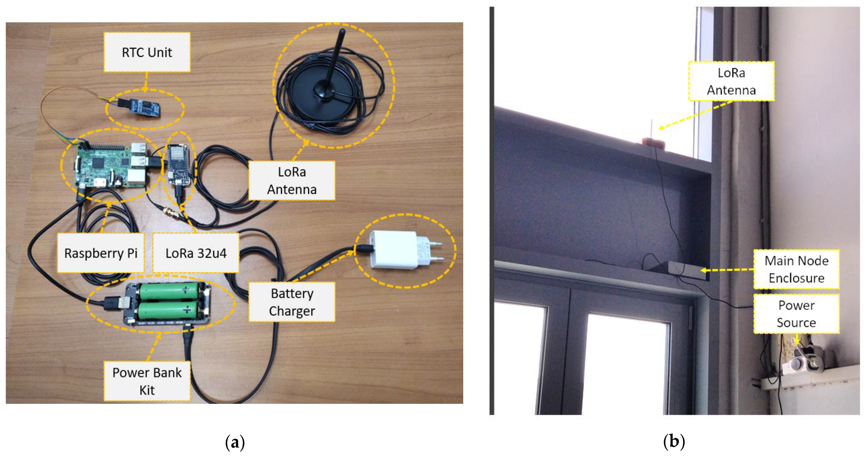
In turn, the data transmitted by the aforementioned nodes were received by a sink node placed approximately 200 m away from the location of irrigation points A and B, inside the university premises. Two farm buildings intervened between the source and the sink nodes. The sink/gateway node followed a simple architecture, equipped with a LoRa receiver module connected to a Raspberry Pi unit (via its USB and hardware serial connection). An omnidirectional LoRa antenna completed the sink/gateway equipment set. As for the sensor/actuator node, this antenna had 50 Ω output resistance, was vertically polarized, was suitable for the 868/915 MHz bands, and was accompanied by a 3 m coaxial cable, for flexible installation options. Further improvements toward operation tolerant to occasional power and cloud connectivity losses suggested that the gateway node be equipped with an Uninterruptible Power Supply (UPS) unit tailored for Raspberry Pi and a dedicated accurate hardware real-time clock (RTC) unit. Figure 6a illustrates details of the components comprising the gateway node, while Figure 6b depicts its final installation position inside the farm systems laboratory premises of our university.
Figure 6.
The gateway utilized by the proposed platform: (a) details of the components comprising the node; (b) final installation position inside the farm systems laboratory of our university.
2.4. Software Component and Interconnection Analysis
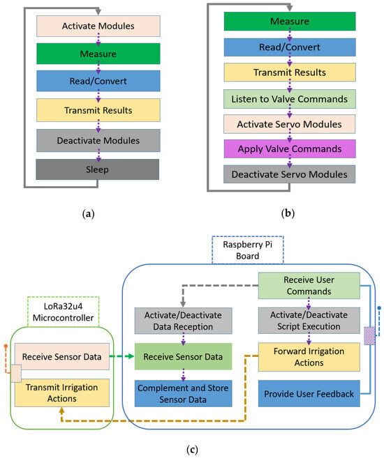
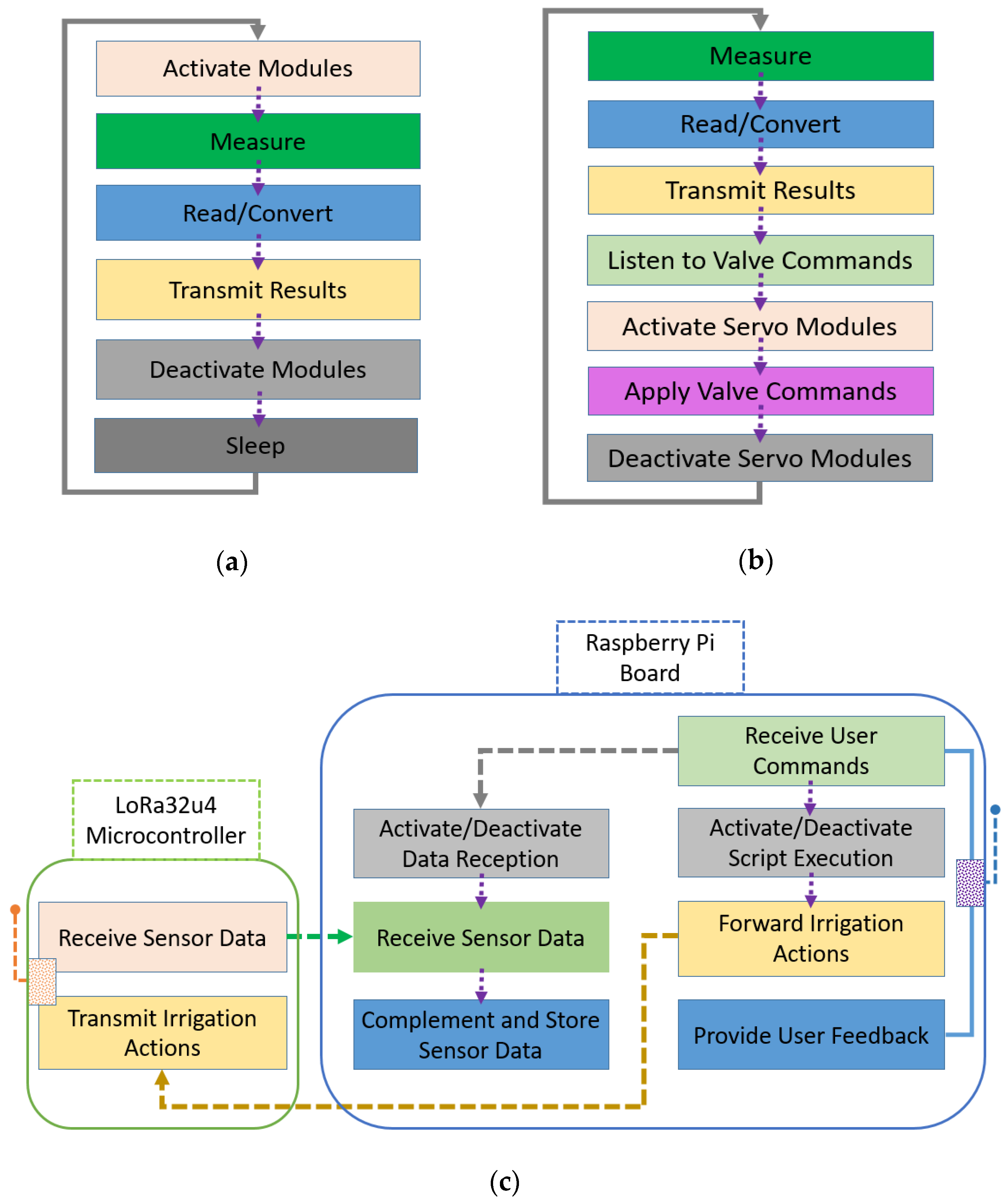
The software on sensing and sensing/actuating nodes was developed using the Arduino IDE environment (software version 1.8.16). There was provision for periodic data report actions and servo-assisted valve control. The elementary functions supported by the sensor (only) node and by the sensor/actuator node are depicted in Figure 7a and in Figure 7b, respectively. Apart from the soil moisture values, the soil temperature (with respect to the TEROS 12’s sensing capabilities), the node internal temperature and battery voltage, the air humidity and temperature at 1 m above ground, and, last but not least, the total water flow and pressure of the irrigation system were reported. The data provided by these two nodes to the sink/gateway contained, apart from a sensor node identifier, a modulo-256 serial number information stamp for interception of potential packet losses, and they were encrypted using the lightweight crypt and speck libraries, which are compatible with the Arduino programming environment.
Figure 7.
Overview of the basic functions implementing the system logic on: (a) the sensing-only node; (b) the sensing/acting node controlling the servo-assisted valves; (c) the sink/gateway node comprising a LoRa-assisted microcontroller and a Raspberry Pi single-board computer.
The sink/gateway node unit, connected via a conventional Wi-Fi Access Point to the university network, was responsible for additional processing and storage of incoming data, as well as for making them available worldwide via common Web and VPN (Virtual Private Network) services, as described in [31]. The aforementioned transparent VPN functionality was supported by the Remote.It [42] environment, thus allowing the utilization of a large set of common useful network (and Web) services (e.g., from a basic SSH console configuration environment to graphical solutions like the RealVNC one). Python (versions 2.7 and 3) and Linux scripts (Bash shell) were utilized for the software development on the sink/gateway unit. On packet data reception, sensor node-specific information was supplemented by the operating system timestamp, in Unix operating system time format (epoch), and by the corresponding received signal strength indicator (RSSI) values, as intercepted and calculated by the sink/gateway node. The nodes provided mainly unprocessed (raw) data requiring further processing (e.g., the application of manufacturer calibration equations) to generate information useful to scientists/farmers. The latter task was performed upon the Raspberry Pi via scripts implemented as explained in [31]. Furthermore, as the updated topology hosts acting elements as well, the central node played the additional role of intercepting irrigation commands and scenarios from the remote users, invoking their execution, and keeping locally the corresponding activity log files. The sensor/actuator node handling the valves was following the directions from the central node, interpreting them in the desired target aperture/closure actions (either partial or complete ones) for the three angle servomotors controlling them. The main functions supported by the sink/gateway node are depicted in Figure 7c.
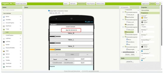
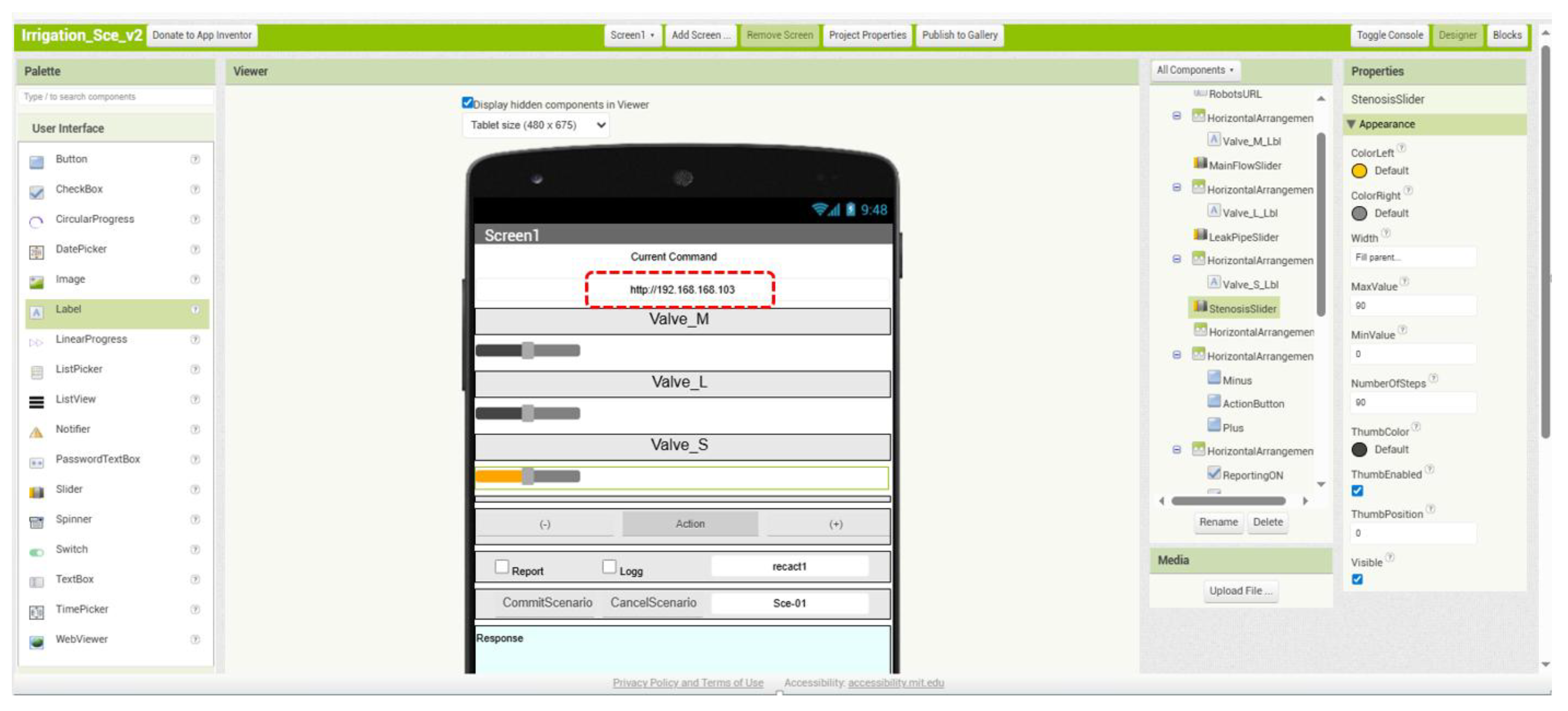
To complement this user-end functionality, a smartphone/tablet-specific application was written, using the MIT App Inventor environment [43]. MIT App Inventor is a block-based programming development platform that provides an easy environment for fast yet efficient application development. More specifically, there is provision for: (a) direct valve aperture (in degrees) following commands; (b) target flow (percentage) following commands incorporating an automatic regulation mechanism. The platform also includes a scenario editor smartphone application allowing for fast scenario script generation. This smartphone application communicated via TCP/IP sockets with the RPi unit of the sink/gateway node to schedule irrigation events and/or to invoke the storage of the corresponding data and, last but not least, to monitor in real time the status of the irrigation process. A characteristic instance of the visual block-based MIT App Inventor environment used to implement the user-end software is depicted in Figure 8.
Figure 8.
A characteristic instance of the visual block-based MIT App Inventor environment used to implement the user-end. During operation, for access via VPN, the uniform resource locator (URL) part (indicated by the red dashed rectangle) should be replaced by the URL provided by the Remote.It tool (e.g., by a string similar to proxy051.r3proxy.com:33501).
3. Results and Evaluation
In order to further communicate the potential of the proposed platform, integrating the hardware and software arrangements being described, characteristic results are presented and analyzed, from both an irrigation-specific point of view and technical point of view.
3.1. Irrigation-Specific Aspects
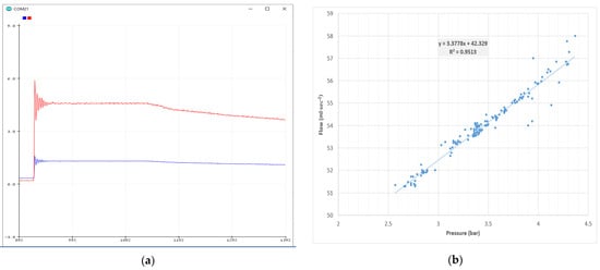
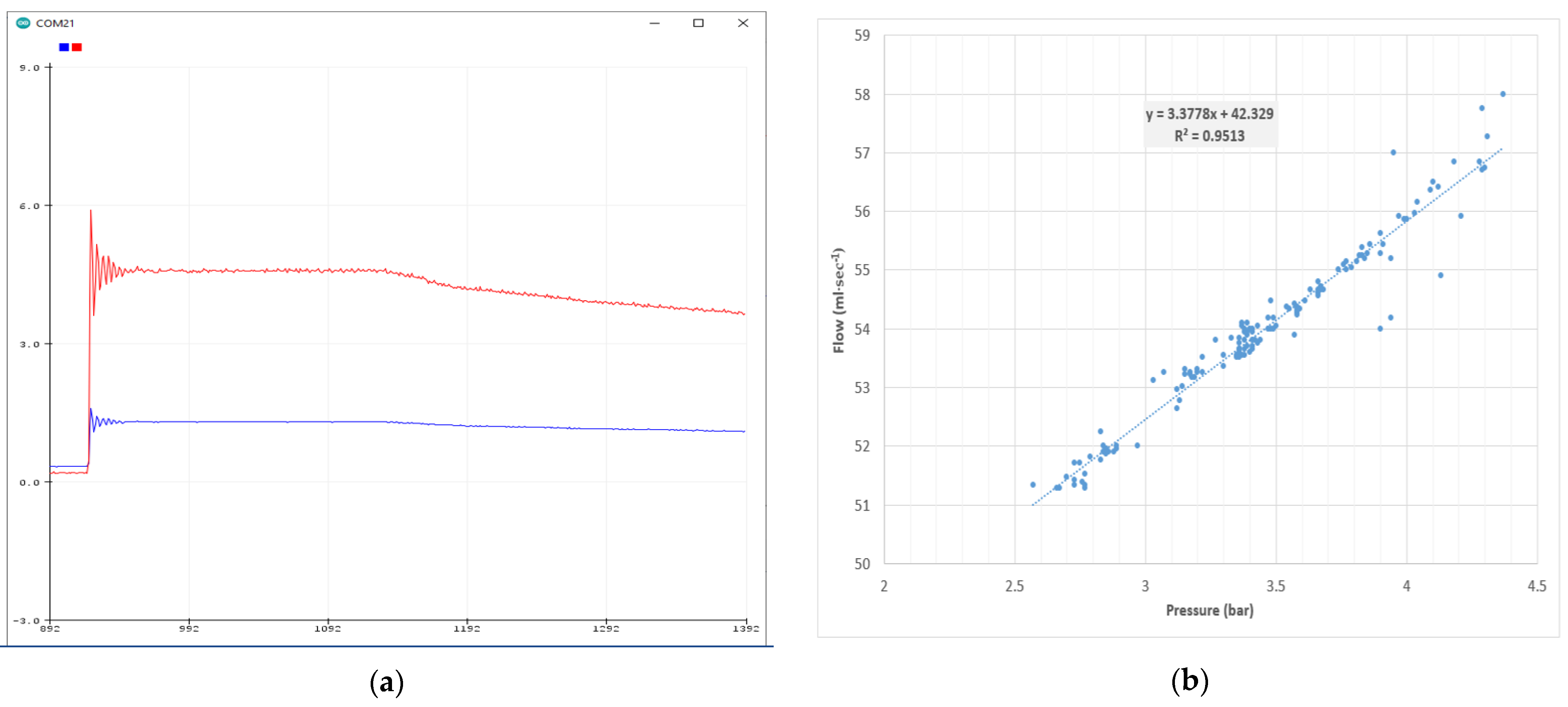
The utilization of a microcontroller harvesting data from liquid pressure and flow sensors allowed for real-time monitoring of several intrinsic irrigation process features. In this regard, Figure 9a illustrates the capture of a high-pressure shockwave following a sudden (manual) opening of the main supply valve, in the absence of a pressure regulator in the piping circuit. The inspection and the extraction of results were facilitated by the Serial Monitor and Serial Plotter (depicted herein) components of the Arduino IDE environment. The plotting interval of consecutive values was set to 5 ms. The pressure evolution (blue curve), although it has a steady-state-level value close to 4.5 bar, is exhibiting oscillations, peaking at 6 bar, that weaken over time. Going further, Figure 9b represents the water flow values inside the drip irrigation system as a function of the pressure inside the piping. This relationship can be described with a satisfactory matching using linear terms for the area of pressure values dominating the irrigation process, i.e., between 2.5 bar and 4.5 bar. This phenomenon might become more complicated over time due to the presence of mineral buildup on the emitters and/or dirt.
Figure 9.
The effects of real-time monitoring of flow and pressure inside the water pipes: (a) capturing the high-pressure shockwave following a sudden (manual) opening of the main supply valve (pressure—red curve; sensor voltage—blue curve); (b) aggregate flow measurement variation inside the drip irrigation system as a function of the incoming water pressure inside the piping.
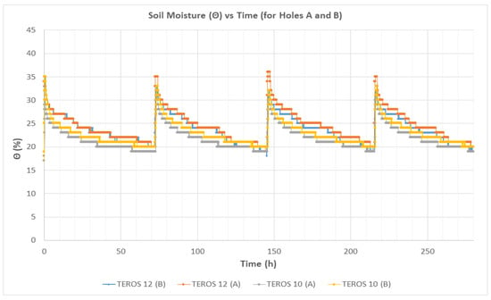
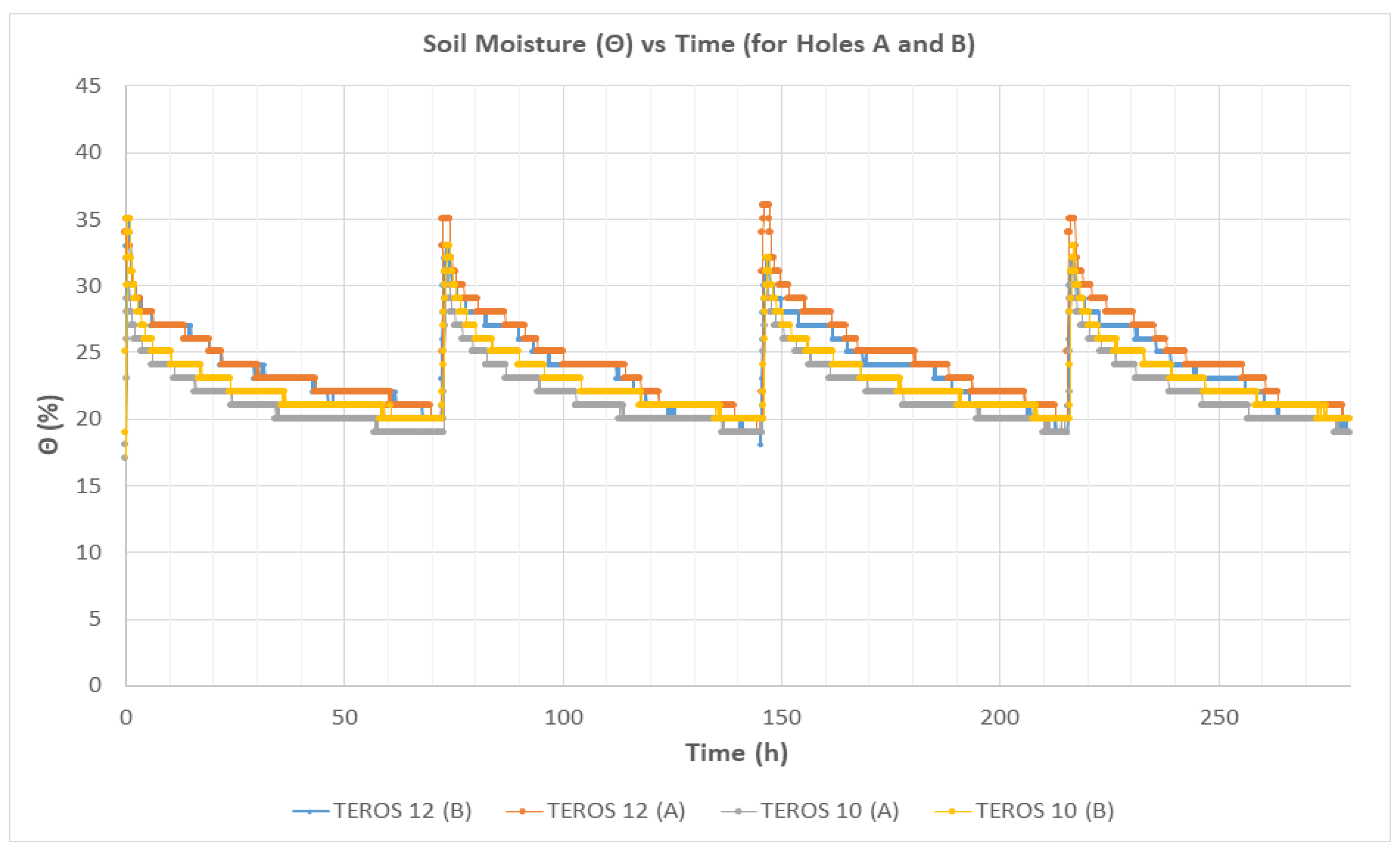
Figure 10 shows the time evolution (in hours) of soil moisture profiles during simultaneous irrigation events at two experimental installations (holes A and B) in a sandy loam soil. Measurements were obtained using TEROS 12 and TEROS 10 sensors installed at depths of 8 cm and 16 cm, respectively. The time series cover the period starting from 29 July to 11 August 2025 and include four irrigation events followed by drying periods between successive applications. Irrigation was started when soil moisture decreased to approximately 19%, which was defined as the lower irrigation threshold. For each irrigation event, 30 lt of water was applied. Irrigation was terminated when soil moisture approached near-saturation conditions, corresponding to θ values of approximately 35%. This resulted in sharp increases in soil moisture immediately after water application. After each irrigation event, soil moisture gradually decreased due to the combined effects of drainage, evaporation, and soil water redistribution. The repeated wetting–drying cycles showed consistent behavior throughout the monitoring period, indicating a stable irrigation management scenario pattern to be used for big data collection.
Figure 10.
Time evolution of simultaneous irrigation events at experimental installations (dugouts) A and B, based on the readings of TEROS 12 and TEROS 10 installed at depths of 8 and 16 cm.
The differences in soil moisture values between sensors installed at depths of 8 and 16 cm can be attributed to the progressive downward movement of the wetting front following irrigation. Applied water infiltrates first into the upper soil layers, resulting in a rapid increase in volumetric water content at 8 cm, whereas the deeper sensor responds as anticipated with a time delay. In addition, the upper soil layer is more strongly affected by evaporation, leading to faster drying rates compared with deeper layers. Differences may also be influenced by variations in soil compaction within the 0–16 cm soil profile, which affect infiltration, water retention and redistribution processes.
More precisely, paired t-tests on the averaged soil moisture values across the four irrigation events showed that moisture at 8 cm depth (TEROS 12) was significantly higher than at 16 cm depth (TEROS 10) in both holes (hole A: p = 4.0 × 10⁻⁵; hole B: p = 0.031). Furthermore, a difference between holes was observed at 16 cm depth (p = 0.0012), whereas no statistically significant difference was detected at 8 cm depth.
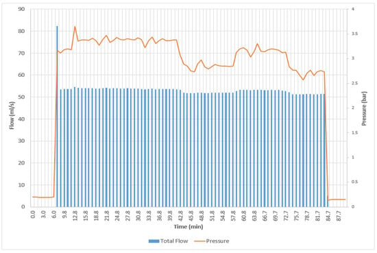
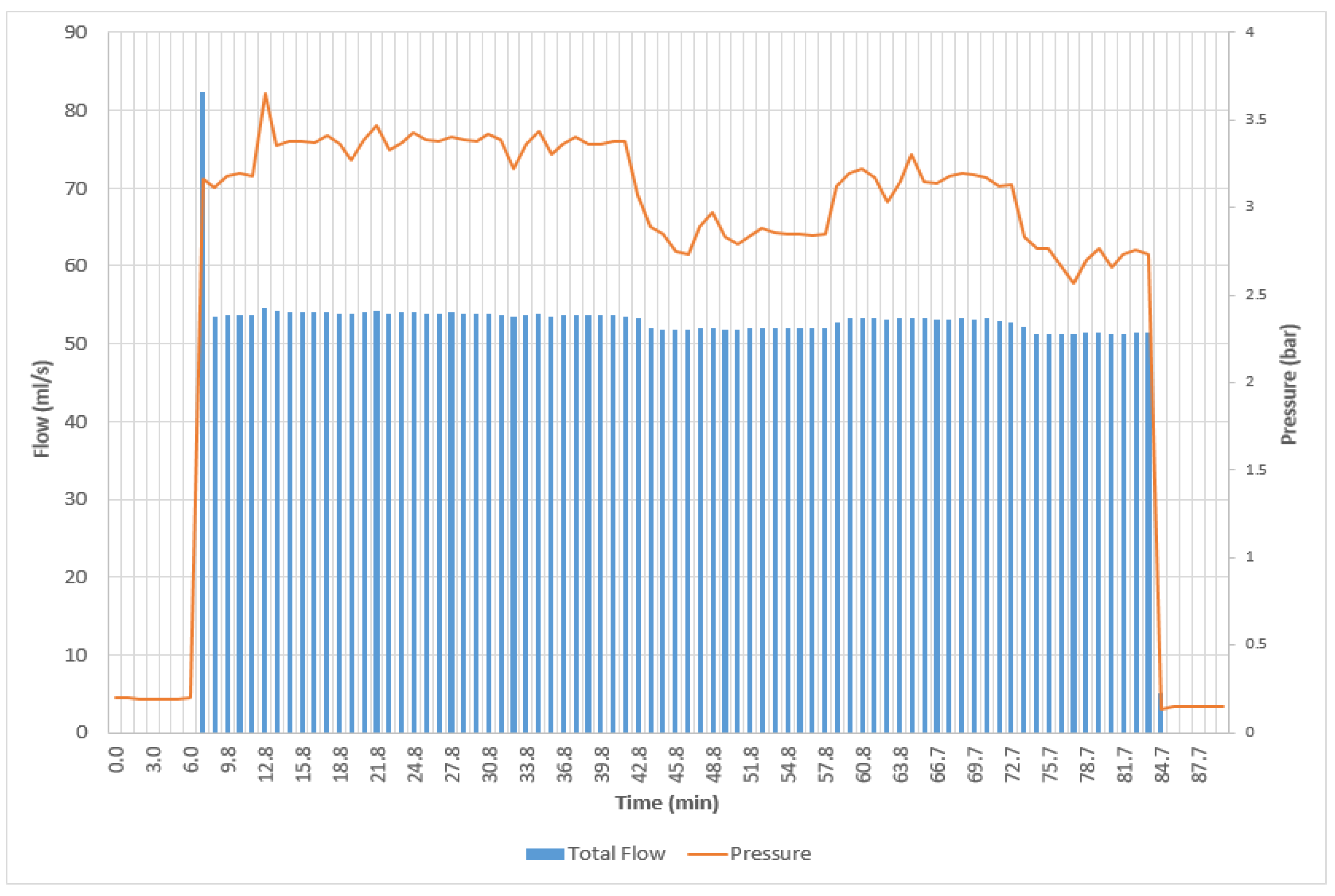
The irrigation platform allowed for the generation of events of different time durations, i.e., either lasting for optimal duration or being shorter/longer than this value. The water flow rate could be adjusted as well, for each of the three valves with key roles, namely M, L, and L, thus generating a large set of irrigation conditions to be gathered. Figure 11 illustrates the total water flow (i.e., passing through the whole system) recordings, in real time, during a specific irrigation event. The duration of this event was close to 75 min, and the flow was close to 53 mL/s for that period. The nearly 50% flow peak at the beginning of this event is attributed to the presence of preexisting air inside the piping system that was rapidly pushed out (via the emitters) by the incoming water following it. The water pressure was initially close to 0 bar, it raised and varied (slightly) around 3 bar during the irrigation event, and it returned to close to 0 bar after this event had finished.
Figure 11.
Time evolution of total flow and pressure quantities during an actual (over)irrigation event at experimental installations (dugouts) A and B, based on the readings of the second sensor/actuator node. A 4/32 amount of water flow was directed to the soil of each dugout.
It should be noted that for the drip irrigation emitter setup being followed, i.e., with four emitters per dugout (two dugouts in total) and also a branch with 24 additional emitters, these arrangements result in a 4/32 amount of total water to be directed to each dugout. Given that the total flow (with Valves M and S completely opened and Valve L closed) was between 53 and 54 mL/s during the majority of our experiments, according to the necessary calculations, this results in a flow value per emitter close to 6 lt/h, which is the factory default. Furthermore, for the aforementioned irrigation event, which is illustrated in Figure 10, the 30 lt water amount per hole is absolutely justified. Finally, with Valve S (i.e., for clogged emitters) completely closed, the total flow dropped to a level around 40 mL/s, which is also justified, as it expresses the 24/32 portion of the value with Valve S opened (i.e., the 53–54 mL/s level).
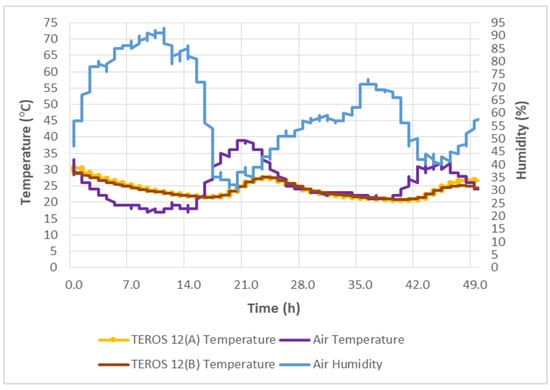
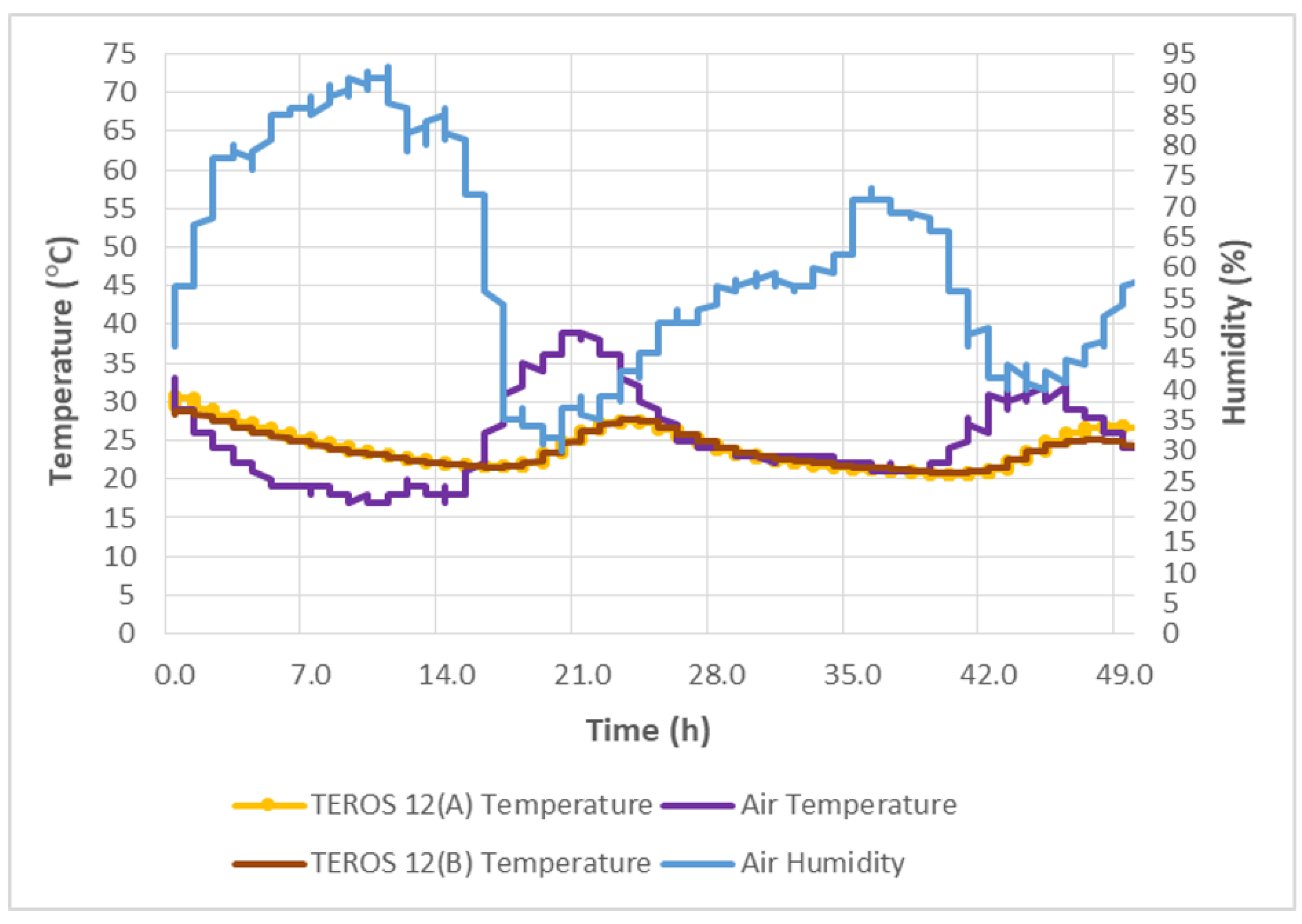
As already mentioned, the proposed agri-field equipment deployment strategy also intercepts and collects complementary (to soil moisture) data, like the air humidity and temperature close to neighboring holes A and B (via the SHTC3 sensor module), and the temperatures inside the soil at a depth of 8 cm (via the TEROS 12 thermistor). These data can contribute to more accurate irrigation decisions, acting as additional input for either conventional or machine learning-based irrigation models. This parameter variation during a two-day (48 h) period is depicted in Figure 12. It is interesting to note the complementarity between air humidity and temperature evolution over time, the less intense variation and the delayed response of temperatures below ground compared with those in open air, and, last but not least, the good match in terms of soil temperatures between dugouts A and B, indicating that both holes were prepared quite meticulously as they have TEROS instruments at the same depth.
Figure 12.
The air humidity and temperature variation close to neighboring holes A and B (provided by the SHTC3 sensor module) and the soil temperatures at 8 cm depth (provided by TEROS 12) at neighboring positions A and B.
3.2. Technical Efficiency Aspects
The experiences gained during the operation of the platform provided valuable feedback indicating the necessity of applying corrective actions.
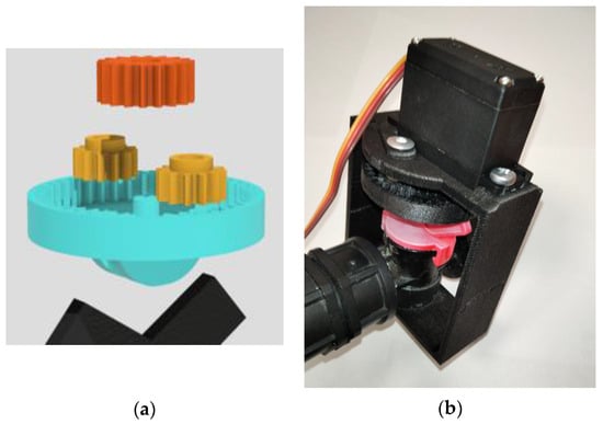
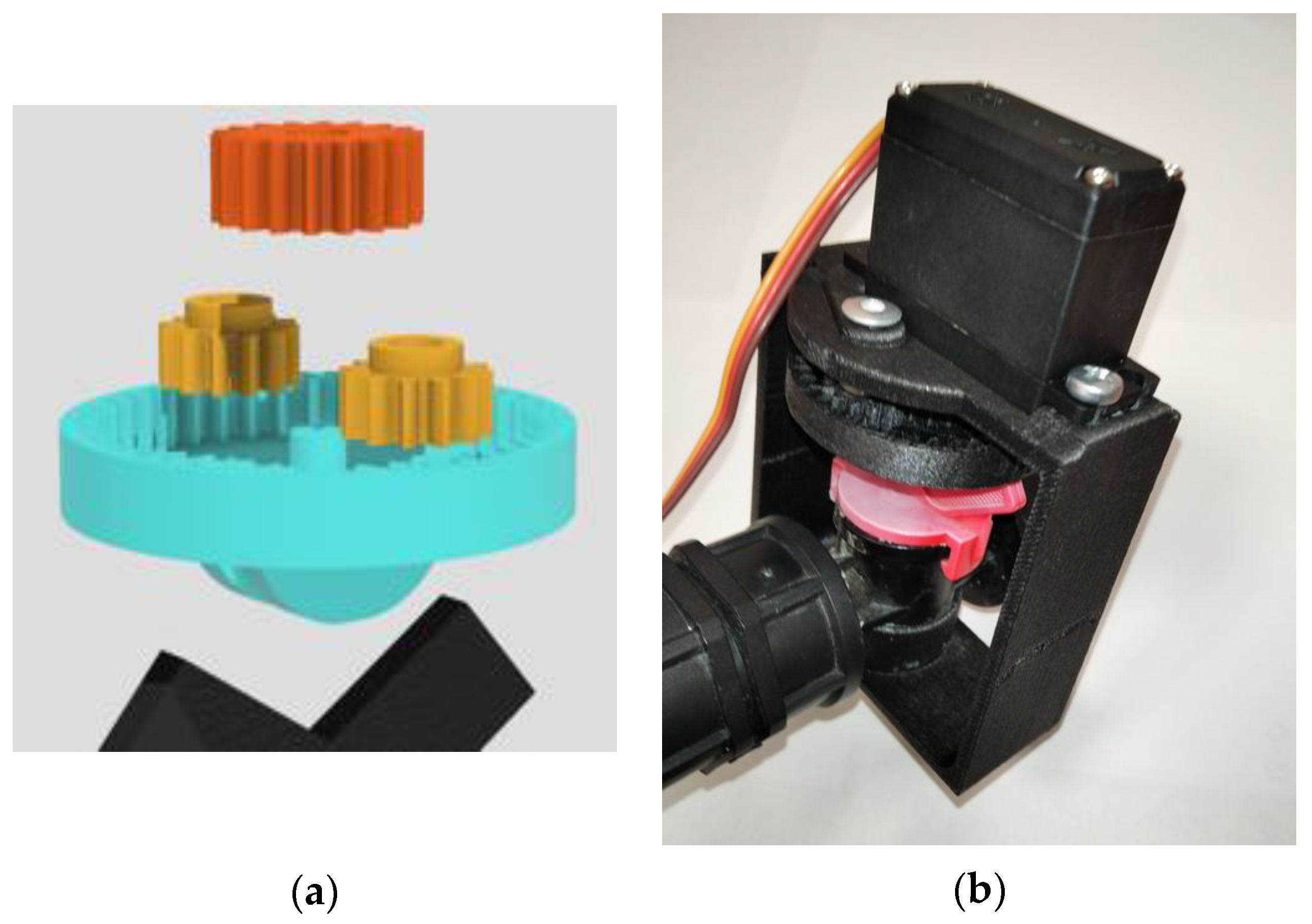
To be more specific, after the first two months in very hot and sunny outdoor weather conditions, the custom servo-assisted valves had to be modified. Indeed, although initial laboratory experiments proved that a typical servo could produce enough torque to rotate the valve directly coupling the servomotor output to the valve handle, long-term exposure of the plastic valve to extreme outdoor temperatures indicated that more torque was required to turn it freely (especially at its first opening change), and thus a custom planetary gear system should be added to fix this issue. This upgraded system (Figure 13a) included a sun gear, two planetary gears, and an internal ring gear hosting them, having a stand in the middle to hold the sun gear in place. In the final assembly, the two planetary gears were kept in place via a metallic rod fixed at the top of the main body’s structure (Figure 13b). These arrangements made the 0–180-degree typical rotational movement range of the servomotor translate to 0–80-degree movement of the actuation axis of the plastic valve, thus providing enough aperture for water supply to the irrigation system and more than doubling the peak torque applied to the valve axis. Furthermore, concerning the 3D filament selection, the extended exposure of the PLA components to direct sunlight led to thermal deformation due to the material’s low glass transition temperature. To address this, an identical CAD file was reprinted using acrylonitrile butadiene styrene (ABS), under identical slicing profiles and printer settings (Figure 13b). Although ABS presents a less environmentally friendly option, it provides enhanced thermal resistance and mechanical robustness, ensuring operational reliability under outdoor environmental conditions [44].
Figure 13.
3D-printed servo valve attachment improvements: (a) 3D design with planetary gears for improved torque output; (b) 3D-printed implementation with ABS for better durability.
The aforementioned ameliorations were easy to apply and maintained cost-effectiveness. Nevertheless, they were not the only ones necessary. Indeed, the timing of the periodic power cycling required for reading the values from the four instruments had to be improved by slightly increasing the delay while acquiring data from the TEROS 12 units of holes A and B, in order for the reading of the incoming data from each of them to be completed without losing the tailing values. Furthermore, interference was also recorded between the LoRa radios and the terrestrial corrective data of a neighboring GNSS-RTK system, utilized for providing guidance to a robotic vehicle on the university campus. The problem was solved by altering the frequency of the RTK system. Furthermore, the transmit power of the nodes was adjusted so as to allow for reception quality close to −100 dBm, thus leaving a −30 dBm sensitivity safety margin before loss of signal.
The consumption of the sensor node was meticulously adjusted and measured in our previous work (Loukatos et al., 2024 [31]) using a custom real-time measuring circuitry of very-fine time granularity (i.e., at 100 sps), based on the ADS1115 16-bit precision ADC module. Via this method, the amperage drain during sleep mode was close to 250 μA, while at idling, it was close to 8 mA (with the LoRa radio and the unnecessary modules disabled). The hosted soil instruments caused an additional amperage drain, via the multiplexer and the powering circuit of the hosting board, i.e., approximately between 8 mA and 12 mA, according to their type. The sensor and the node health status data transmission (nearly 60 B) every 5 min required approximately another 90 mA for a 100 ms period. The LoRa transmitter was set to moderate power settings (i.e., with the coding rate set to 4/5, the bandwidth set to 128 kHz, the spreading factor set to 7, and the transmit power set to 14 dBm). Values in mW can be easily calculated using the above current consumption data, given that the battery voltage was close to 4.1 V, during sensor node operation, with respect to the small solar panel attached to it.
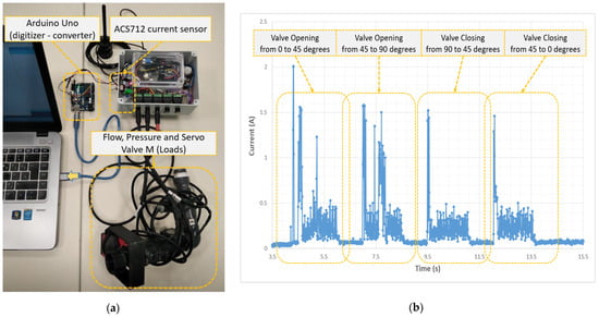
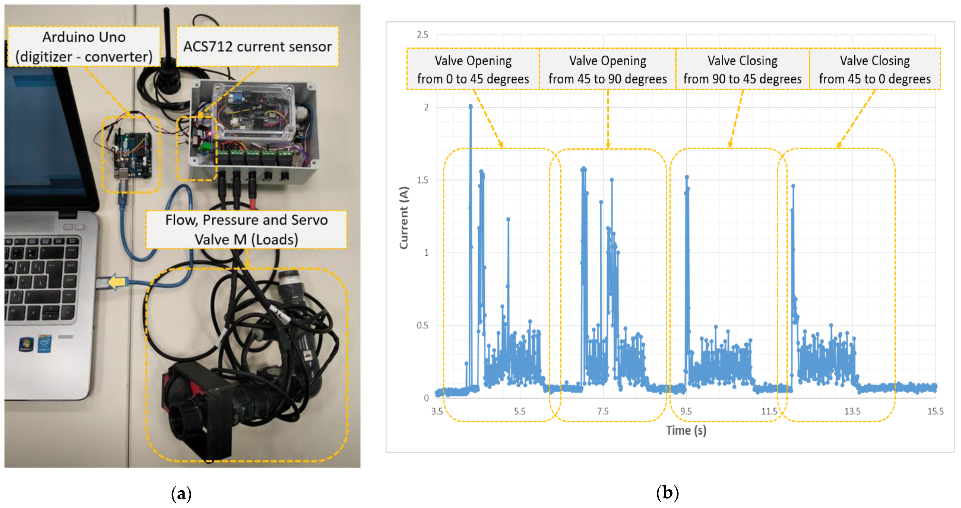
The amperage consumption of the sensor–actuator node controlling the valves and reporting the flow and pressure data is quite interesting to study herein, as this node exhibited a drastically changing amperage consumption profile due to the need for feeding of the servomotors moving the valves. For this reason, the amperage consumption measurements were extracted using an ACS712 Hall-based sensor unit, connected to an Arduino Uno microcontroller to handle the corresponding digitization and data conversion tasks (Figure 14a). This setup provided recordings varying from 10 mA (with the node idling without sensors or servos) to nearly 2 A (with the sensors connected and the servomotors rotating the corresponding plastic valves, one after the other). Such an amperage recording case is shown in Figure 14b, where consecutive average consumption values are plotted every 10 ms, for the sensor–actuator node. Further experimentation with 3D-printed housing suitable for metal valves instead of plastic ones showed smoother behavior with fewer current spikes that did not exceed the 1 A level. Finally, it should be mentioned that the sensor-actuator node, like the sensor node, also produced smaller periodic current spikes (approximately 90 mA in magnitude, for a few tens of milliseconds each), due to the periodic reporting of flow and pressure data to the sink/gateway node.
Figure 14.
3D-printed servo valve attachment improvements: (a) custom amperage measuring unit based on ACS712 Hall-based sensor; (b) sensor–actuator node amperage consumption (at 3.8 V) while progressively opening and closing main water supply valve (Valve M).
The sink/gateway node, as already mentioned, had a permanent power supply, and its amperage consumption was almost constant, i.e., close to the 250 mA level, exhibiting only sporadic additional raises by almost 90 mA for an approximately 40 ms period, whenever irrigation commands had to be passed to the sensor–actuator node.
4. Discussion and Future Perspectives
The work presented here provides many details on how a cost-effective but efficient irrigation event emulation and monitoring system can be designed and implemented, offering, in parallel, a very accurate way to identify the effect of even negligible changes in soil environment parameters, e.g., stepping near the irrigation points or the appearance of new plants therein. This further shifts the standards for accurate experiment setup preparation or for verification of the irrigation formulas for certain soil types.
In the proposed platform, we utilized TEROS 10 and TEROS 12 modules by the Meter company because they are widely used by the research community and have well-known performance characteristics, despite their non-negligible cost. Nevertheless, this does not limit the applicability of the prototype irrigation event emulation and monitoring methods being presented, provided that the corresponding manufacturer calibration equations are incorporated into participating firmware. In our previous work [31], we showcased the feasibility of utilizing similar node hardware and software arrangements to support a wider set of sensors, including analog and digital modules, like inexpensive capacitive soil moisture units, Decagon Devices 10HS and 5TE units, Delta-T Devices ML2 sensors, and, last but not least, TEROS 10 and TEROS 12 instruments.
Excluding the purchase cost of TEROS 10 and TEROS 12 instruments, which is close to EUR 250 and EUR 550 per unit, respectively, the rest of the equipment remains highly affordable. More specifically, the total cost of the discussed sensor (only) node suitable for up to two dugouts (i.e., typically four soil moisture sensors), comprising EUR 35 for the LoRa32u4 development board and its antenna, EUR 10 for the powering circuits, EUR 5 for the solar panel, EUR 10 for the 3.5 mm plugs, EUR 3 for the multiplexer/demultiplexer, EUR 5 for the SHTC3 module, EUR 5 for the Li-Ion battery and its socket, EUR 8 for a proper plastic enclosure box, and close to EUR 10 for the rest of the tinkering components, was around EUR 90. The sensor/actuator node, which is diversified from its pure sensing counterpart as it has flow (+EUR 5) and pressure (+EUR 15) units on it, as well as three servo-assisted valve units (+EUR 15 per unit) and a stronger powering subsystem (+EUR 10), costs close to EUR 160. The sink/gateway node required EUR 55 for Raspberry Pi Model 4, EUR 30 for the LoRa32u4 board, EUR 5 for the RTC module, EUR 5 for a plastic enclosure box, and EUR 30 for the power-supplying part including the batteries, resulting in a total cost for this node type close to EUR 125.
At this point, it is interesting to note that a large number of emulated irrigation events should be necessary for efficient neural network model training, e.g., for identifying irrigation emitter stenosis or over-irrigation incidents. With respect to the idiosyncrasies of the soil monitoring process, most irrigation-specific parameters are collected at a frequency of 12 samples per hour (i.e., every 5 min), and the main irrigation process typically lasts from 30 min to 90 min, while a 2–3-day time period is necessary before the next irrigation process is invoked for the same area. These characteristics signify that several days should pass in order for an adequate number of samples to be collected. This period can be reduced by increasing the number of dugouts participating in the experiment. The platform we are proposing is well-defined and modular and thus provisions for diversification of data recordings per sensor node (via a dedicated sensor node identifier field), while each node is responsible for up to two dugouts. These arrangements allow for flawless escalated platform deployment meeting big data collection requirements, at a cost level that is a multiple of the cost of the basic installation presented herein.
The discussed irrigation events should belong to different classes, but should not be identical, to avoid model overfitting to the data used for training. Thankfully, experiments being performed verify that nature creates enough variability itself that the soil composition at points A and B can never be identical, neither their compaction degree nor the depth at which the corresponding TEROS instruments have been placed. Nearby trees and buildings introduce additional diversification of values being recorded as well as temporal differences in the water supply pressure. This nature-derived variability can be augmented by allowing small changes per emulated event category, in factors like the aperture of the valves or the duration of the irrigation action, allowing the critical parameter (i.e., the angle or the duration) to conform to statistically defined uncertainties (i.e., to follow specific statistical distribution laws), as implemented for network traffic generation events in the past [45].
Despite the remarkable improvement in water usage that modern irrigation techniques (like drip irrigation) can achieve, performance can seriously degrade from a 90 to 95% water efficiency level, resulting in uneven water supply, under/over-pressure extremes, and/or leak problems [46,47]. We claim not that the platform we are proposing achieves a specific amount of irrigation water savings, but that it contributes to the preservation of/an increase in the benefits of modern irrigation practices, like drip irrigation. This goal is achieved as it provides infrastructure guidelines for emulating a large variety of irrigation events and for gathering the corresponding data, while its component selection potential can be used to support smart watering action monitoring, characterization and scheduling. The experiences gained contribute to the understanding of the need for the development of multilevel mechanisms (in terms of time) orchestrating the irrigation process, able to:
- Allow the execution of user-defined condition irrigation scenarios (i.e., corresponding to cases like normal operation, leak, blown valve, low water supply, emitter stenosis, over-irrigation);
- Schedule watering events of a specific/optimal duration according to the season and to environmental conditions and cultivation (based on a priori underlying model calculations);
- Perform watering events according to the feedback provided by the soil moisture instruments;
- Immediately (i.e., in a few minutes) intercept urgent situations (like blown emitters or valves), provide information about them and automatically handle them properly, i.e., by cutting the water supply;
- Identify and provide information about less intense problems (i.e., in locally clogged emitters or in small pipe system leaks), whenever they occur (i.e., in 30–100 min);
- Provide manual fluent manual overdrive options, as automatic systems can always fail.
It is apparent that several points require further investigation, such as standardizing the format of the data being recorded and of the irrigation scenarios to be followed, increasing the ease of defining and executing irrigation events via visual tools, and further facilitating the processes of collecting/characterizing the corresponding data and of training the neural network models. Long-term data collection in different seasons/environmental conditions will be necessary to efficiently train the system for identifying irrigation process quality and potential malfunctions, without excluding synergies with analytical hydrological formulas and methods for improved results.
5. Conclusions
The work presented here sheds light on methods in which soil moisture instruments can be combined with low-end microcontrollers, energy-efficient communication protocols, single-board computers, flow and pressure sensors, and purpose-built actuators to emulate and to monitor a diverse set of realistic user-defined (and potentially not optimal) irrigation event scenarios. The result was an ecosystem able to generate and to collect multimodal irrigation-sensitive data, whose physiology and performance were communicated via in situ experimental testing. A roadmap for an exploitation paradigm was also proposed, so that these data can be used for the early detection of water misuse cases and of potential irrigation failures, and for optimal precision irrigation actions, meeting the modern sustainable growth orientation.
Author Contributions
Conceptualization, D.L.; methodology, D.L., A.F., P.L. and G.K.; software, D.L.; prototyping, D.L.; validation, D.L., A.F., P.L. and G.K.; formal analysis, D.L., A.F., P.L., L.M. and G.K.; investigation, D.L.; data curation, D.L. and A.F.; writing—original draft preparation, D.L., A.F. and P.L.; writing—review and editing, D.L., P.L., L.M., G.K. and K.G.A.; visualization, D.L., A.F. and P.L.; supervision, K.G.A.; project administration, D.L. and G.K. All authors have read and agreed to the published version of the manuscript.
Funding
This research received no external funding.
Data Availability Statement
The data presented in this study are available upon request from the corresponding author.
Conflicts of Interest
The authors declare no conflicts of interest.
References
- FAO. The State of the World’s Land and Water Resources for Food and Agriculture: Managing Systems at Risk; FAO: Rome, Italy, 2018. [Google Scholar]
- Department of Economic and Social Affairs. World Population Prospects 2024: Summary of Results; Stylus Publishing, LLC: Sterling, VA, USA, 2024. [Google Scholar]
- Godfray, H.C.J. The debate over sustainable intensification. Food Secur. 2015, 7, 199–208. [Google Scholar] [CrossRef] [Scilit]
- Boretti, A.; Rosa, L. Reassessing the projections of the world water development report. NPJ Clean Water 2019, 2, 15. [Google Scholar] [CrossRef] [Scilit]
- De Fraiture, C.; Wichelns, D. Satisfying future water demands for agriculture. Agric. Water Manag. 2010, 97, 502–511. [Google Scholar] [CrossRef] [Scilit]
- Islam, S.M.F.; Karim, Z. World’s demand for food and water: The consequences of climate change. In Desalination-Challenges and Opportunities; IntechOpen: London, UK, 2019. [Google Scholar]
- McKenzie, F.C.; Williams, J. Sustainable food production: Constraints, challenges and choices by 2050. Food Secur. 2015, 7, 221–233. [Google Scholar] [CrossRef] [Scilit]
- Hubert, B.; Rosegrant, M.; Van Boekel, M.A.; Ortiz, R. The future of food: Scenarios for 2050. Crop Sci. 2010, 50, S-33–S-50. [Google Scholar] [CrossRef] [Scilit]
- Wichelns, D.; Drechsel, P.; Qadir, M. Wastewater: Economic asset in an urbanizing world. In Wastewater: Economic Asset in an Urbanizing World; Springer: Dordrecht, The Netherlands, 2015; pp. 3–14. [Google Scholar]
- Loucks, D.P. Managing water as a critical component of a changing world. Water Resour. Manag. 2017, 31, 2905–2916. [Google Scholar] [CrossRef] [Scilit]
- Alamanos, A. Water resources planning under climate and economic changes in Skiathos island, Aegean. AQUA—Water Infrastruct. Ecosyst. Soc. 2021, 70, 1085–1093. [Google Scholar] [CrossRef] [Scilit]
- Makanda, K.; Nzama, S.; Kanyerere, T. Assessing the role of water resources protection practice for sustainable water resources management: A review. Water 2022, 14, 3153. [Google Scholar] [CrossRef] [Scilit]
- Kosolapova, N.A.; Matveeva, L.G.; Nikitaeva, A.Y.; Molapisi, L. The rational use of water resources in the strategy of industry 4.0. Water Resour. Manag. 2021, 35, 3023–3041. [Google Scholar] [CrossRef] [Scilit]
- Kumar, P.; Choudhury, D. Innovative Technologies for Effective Water Resources Management. In Water Crises and Sustainable Management in the Global South; Springer: Singapore, 2024; pp. 555–594. [Google Scholar]
- Farooq, M.S.; Riaz, S.; Abid, A.; Umer, T.; Zikria, Y.B. Role of IoT Technology in Agriculture: A Systematic Literature Review. Electronics 2020, 9, 319. [Google Scholar] [CrossRef] [Scilit]
- Gaitan, N.C.; Batinas, B.I.; Ursu, C.; Crainiciuc, F.N. Integrating Artificial Intelligence into an Automated Irrigation System. Sensors 2025, 25, 1199. [Google Scholar] [CrossRef] [Scilit] [PubMed]
- Abdelmoneim, A.A.; Kimaita, H.N.; Al Kalaany, C.M.; Derardja, B.; Dragonetti, G.; Khadra, R. IoT sensing for advanced irrigation management: A systematic review of trends, challenges, and future prospects. Sensors 2025, 25, 2291. [Google Scholar] [CrossRef] [Scilit] [PubMed]
- Ali, A.; Hussain, T.; Zahid, A. Smart irrigation technologies and prospects for enhancing water use efficiency for sustainable agriculture. Agri. Eng. 2025, 7, 106. [Google Scholar] [CrossRef] [Scilit]
- Qian, M.; Qian, C.; Xu, G.; Tian, P.; Yu, W. Smart irrigation systems from cyber–physical perspective: State of art and future directions. Future Internet 2024, 16, 234. [Google Scholar] [CrossRef] [Scilit]
- Sinobas, L.R.; Rodríguez, M.G.; Lee, T.S. A review of subsurface drip irrigation and its management. In Water Quality, Soil and Managing Irrigation of Crops; IntechOpen: London, UK, 2012; pp. 171–194. [Google Scholar]
- Paris, P.; Di Matteo, G.; Tarchi, M.; Tosi, L.; Spaccino, L.; Lauteri, M. Precision subsurface drip irrigation increases yield while sustaining water-use efficiency in Mediterranean poplar bioenergy plantations. For. Ecol. Manag. 2018, 409, 749–756. [Google Scholar] [CrossRef] [Scilit]
- Bush, A.; Elamin, A.M.; Ali, A.B.; Hong, L. Effect of different operating pressures on the hydraulic performance of drip irrigation system in Khartoum State conditions. J. Environ. Agric. Sci. 2016, 6, 64–68. [Google Scholar]
- Rajak, P.; Ganguly, A.; Adhikary, S.; Bhattacharya, S. Internet of Things and smart sensors in agriculture: Scopes and challenges. J. Agric. Food Res. 2023, 14, 100776. [Google Scholar] [CrossRef] [Scilit]
- Millán, S.; Montesinos, C.; Campillo, C. Evaluation of different commercial sensors for the development of their automatic irrigation system. Sensors 2024, 24, 7468. [Google Scholar] [CrossRef] [Scilit]
- Pereira, G.P.; Chaari, M.Z.; Daroge, F. IoT-enabled smart drip irrigation system using ESP32. IoT 2023, 4, 221–243. [Google Scholar] [CrossRef] [Scilit]
- Correa-Quiroz, J.J.; Toribio-Barrueto, M.A.; Castro-Vargas, C. IoT system with ESP32 for smart drip irrigation and climate monitoring in greenhouses. Emerg. Sci. J. 2025, 9, 1133–1157. [Google Scholar] [CrossRef] [Scilit]
- Inayah, I.; Agustirandi, B.; Budiman, M.; Djamal, M.; Faizal, A. Experimental design: Implementation of IoT-based drip irrigation to enhance the productivity of Cilembu sweet potato (Ipomoea batatas) cultivation. Results Eng. 2025, 25, 103600. [Google Scholar] [CrossRef] [Scilit]
- Rajasekaran, C.; Gokul, L.; Gowsalya, D.; Manimaran, R. Lora based smart irrigation system. Int. J. Health Sci. 2022, 6, 5996–6010. [Google Scholar] [CrossRef] [Scilit]
- Pius Agbulu, G.; Joselin Retna Kumar, G. A LoRa-based internet of things smart irrigation control solution with hybrid classifier CNN-SVM. Wirel. Pers. Commun. 2024, 137, 523–539. [Google Scholar] [CrossRef] [Scilit]
- Ercan Oğuztürk, G.; Murat, C.; Yurtseven, M.; Oğuztürk, T. The Effects of AI-Supported Autonomous Irrigation Systems on Water Efficiency and Plant Quality: A Case Study of Geranium psilostemon Ledeb. Plants 2025, 14, 770. [Google Scholar] [CrossRef] [Scilit]
- Loukatos, D.; Fragkos, A.; Kargas, G.; Arvanitis, K.G. Implementation and Evaluation of a Low-Cost Measurement Platform over LoRa and Applicability for Soil Monitoring. Future Internet 2024, 16, 443. [Google Scholar] [CrossRef] [Scilit]
- Miller, T.; Mikiciuk, G.; Durlik, I.; Mikiciuk, M.; Łobodzińska, A.; Śnieg, M. The IoT and AI in Agriculture: The Time Is Now—A Systematic Review of Smart Sensing Technologies. Sensors 2025, 25, 3583. [Google Scholar] [CrossRef] [Scilit]
- Mao, Y.; Liu, S.; Nahar, J.; Liu, J.; Ding, F. Soil moisture regulation of agro-hydrological systems using zone model predictive control. Comput. Electron. Agric. 2018, 154, 239–247. [Google Scholar] [CrossRef] [Scilit]
- García-Mollá, M.; Medina, R.P.; Vega-Carrero, V.; Sanchis-Ibor, C. Economic efficiency of drip and flood irrigation. Comparative analysis at farm scale using DEA. Agric. Water Manag. 2025, 309, 109314. [Google Scholar] [CrossRef] [Scilit]
- Alla, A.; Berardi, M.; Saluzzi, L. State Dependent Riccati for dynamic boundary control to optimize irrigation in Richards’ equation framework. Math. Comput. Simul. 2025, 232, 261–275. [Google Scholar] [CrossRef] [Scilit]
- Amanatidis, P.; Lyratzis, E.; Angelopoulos, V.; Kouloumpris, E.; Skaperdas, E.; Bassiliades, N.; Vlahavas, I.; Maris, F.; Emmanouloudis, D.; Karampatzakis, D. Intelligent Water Management Through Edge-Enabled IoT, AI, and Big Data Technologies. IoT 2026, 7, 5. [Google Scholar] [CrossRef] [Scilit]
- METER Group. TEROS 12 Instrument Description. Available online: https://www.labcell.com/media/140632/teros12%20manual.pdf (accessed on 10 December 2025).
- METER Group. TEROS 10 Instrument Description. Available online: https://www.misure.net/sites/default/files/pdf/20788_TEROS10_Manual_Web.pdf (accessed on 10 December 2025).
- Fragkos, A.; Loukatos, D.; Kargas, G.; Arvanitis, K.G. Performance Evaluation of TEROS 10 Sensor in Diverse Substrates and Soils of Different Electrical Conductivity Using Low-Cost Microcontroller Settings. Land 2025, 14, 242. [Google Scholar] [CrossRef] [Scilit]
- Cominelli, S.; Rivera, L.D.; Brown, W.G.; Ochsner, T.E.; Patrignani, A. Calibration of TEROS 10 and TEROS 12 electromagnetic soil moisture sensors. Soil Sci. Soc. Am. J. 2024, 88, 2104–2122. [Google Scholar] [CrossRef] [Scilit]
- Fragkos, A.; Loukatos, D.; Kargas, G.; Arvanitis, K.G. Response of the TEROS 12 soil moisture sensor under different soils and variable electrical conductivity. Sensors 2024, 24, 2206. [Google Scholar] [CrossRef] [Scilit]
- Remote.It. Instant, Secure, and Code-Based Networking Solutions for Seamless Network Connectivity. Available online: https://www.remote.it/ (accessed on 10 December 2025).
- MIT App Inventor. The MIT App Inventor Programming Environment. Available online: http://appinventor.mit.edu/explore/ (accessed on 10 December 2025).
- Głowacki, M.; Mazurkiewicz, A.; Słomion, M.; Skórczewska, K. Resistance of 3D-Printed Components, Test Specimens and Products to Work under Environmental Conditions—Review. Materials 2022, 15, 6162. [Google Scholar] [CrossRef] [Scilit]
- Loukatos, D.; Sarakis, L.; Kontovasilis, K.; Skianis, C.; Kormentzas, G. Tools and Practices for Measurement-Based Network Performance Evaluation. In Proceedings of the 2007 IEEE 18th International Symposium on Personal, Indoor and Mobile Radio Communications, Athens, Greece, 3–7 September 2007; IEEE: New York, NY, USA, 2007; pp. 1–5. [Google Scholar] [CrossRef] [Scilit]
- Shi, K.; Lu, T.; Zheng, W.; Zhang, X.; Zhangzhong, L. A Review of the Category, Mechanism, and Controlling Methods of Chemical Clogging in Drip Irrigation System. Agriculture 2022, 12, 202. [Google Scholar] [CrossRef] [Scilit]
- Lakhiar, I.A.; Yan, H.; Zhang, C.; Wang, G.; He, B.; Hao, B.; Han, Y.; Wang, B.; Bao, R.; Syed, T.N.; et al. A Review of Precision Irrigation Water-Saving Technology under Changing Climate for Enhancing Water Use Efficiency, Crop Yield, and Environmental Footprints. Agriculture 2024, 14, 1141. [Google Scholar] [CrossRef] [Scilit]
Disclaimer/Publisher’s Note: The statements, opinions and data contained in all publications are solely those of the individual author(s) and contributor(s) and not of MDPI and/or the editor(s). MDPI and/or the editor(s) disclaim responsibility for any injury to people or property resulting from any ideas, methods, instructions or products referred to in the content. |
© 2026 by the authors. Licensee MDPI, Basel, Switzerland. This article is an open access article distributed under the terms and conditions of the Creative Commons Attribution (CC BY) license.