


Abstract
High-velocity oxy-fuel (HVOF) spraying was used to deposit WC-Co and WC-Co-Cr coatings on high-speed steel in order to determine how binder chemistry and coating thickness jointly control load support, friction, and dry sliding wear resistance. Nominal 50 and 100 µm coatings were compared within the same substrate framework by XRD, FT-IR, SEM/EDX, cross-sectional image analysis, Vickers hardness testing, dry sliding wear testing, and post-wear SEM/EDX. The coatings retained WC as the dominant crystalline phase, while weak overlapping features were associated with binder-rich regions and limited decarburization products. Cross-sectional observations confirmed continuous coating build-up close to the nominal thicknesses and low apparent dark-feature/porosity fractions. All WC-based coatings increased the effective hardness and reduced mass loss relative to uncoated HSS. Among the tested conditions, WC-Co-Cr-100 provided the highest effective hardness and the lowest mass loss after 1000 m sliding, whereas WC-Co-100 produced the lowest mean coefficient of friction. The results show that low friction and high wear resistance are not governed by identical mechanisms: WC-Co favours interfacial shear reduction, while the thicker Cr-containing coating provides superior resistance to material removal through improved carbide retention, binder stability, and coating-scale load support.
1. Introduction
High-speed steel (HSS) remains an important substrate material for cutting tools, forming tools, dies, wear rings, and highly loaded components because its tempered martensitic matrix and alloy carbide network provide high hardness, red hardness, and resistance to local plastic deformation. In severe contact conditions, however, the intrinsic strength of HSS is not always sufficient to suppress surface-initiated damage. Abrasive grooving, adhesive junction rupture, tribo-oxidation, and carbide fragmentation can progressively expose fresh metallic surfaces, accelerate third-body abrasion, and reduce dimensional stability. For this reason, surface-engineering approaches are widely used to decouple the load-bearing function of the substrate from the chemically and tribologically active outer surface [1,2,3,4].
Among the coating systems used for HSS and other tool steel substrates, thermally sprayed WC-Co coatings are among the most established carbide-metal cermet architectures. Their performance originates from the combination of hard WC grains and a ductile Co-based binder that accommodates impact deformation during deposition and later distributes contact stresses during sliding or abrasion. The final coating response is governed not only by the nominal composition but also by feedstock powder structure, carbide size, particle temperature, particle velocity, degree of melting, decarburization, splat cohesion, porosity, residual stress, and coating/substrate interfacial quality [5,6,7].
Compared with atmospheric plasma spraying, high-velocity oxy-fuel (HVOF) spraying generally produces WC-based coatings with lower porosity, lower oxide content, higher particle impact velocity, and better preservation of carbide phases because particle residence time at high temperatures is shorter. The resulting microstructure is a lamellar stack of plastically deformed splats, embedded WC grains, binder-rich interlamellar regions, and local pores or unmelted/partially melted particles. This architecture can provide high wear resistance, but it also makes coating performance sensitive to local defects, splat boundaries, and residual stress fields [8,9,10,11].
The addition of chromium to the Co binder has become particularly important in WC-Co-Cr coatings. Cr can improve corrosion resistance and modify binder chemistry while maintaining the hard WC skeleton that controls abrasion resistance. At the same time, Cr-containing binder phases and carbide transformations can alter the XRD response, local oxidation behaviour, and mechanical integrity of the coating. Comparative studies of WC-Co and WC-Co-Cr systems therefore require simultaneous evaluation of phase constitution, surface morphology, elemental distribution, and coating thickness rather than a single hardness or wear metric [12,13,14,15].
Coating thickness is another key design variable. In HVOF spraying, increasing thickness generally requires additional passes or a modified layer build-up strategy. Thicker coatings may improve barrier continuity and load support, but excessive thickness can increase residual stress, roughness, interlamellar cracking risk, and edge build-up. For thin or nominally single-layer coatings, local discontinuities or porosity may be more influential, while double-layer designs can provide greater coverage and damage tolerance if interpass cohesion remains strong [16,17,18].
Therefore, the present study aims to establish a systematic structure–property–performance relationship for HVOF-sprayed WC-Co and WC-Co-Cr coatings deposited on high-speed steel substrates at nominal thicknesses of 50 and 100 µm. Particular attention is given to the influence of Cr addition and coating thickness on phase formation, surface morphology, elemental distribution, lamellar coating integrity, and coating/substrate interfacial continuity. XRD and FT-IR analyses were employed to determine the crystalline phase constitution and near-surface chemical bonding characteristics, while SEM, EDX, elemental mapping, and cross-sectional thickness measurements were used to evaluate coating architecture, compositional homogeneity, and thickness uniformity. In addition, Vickers hardness measurements and pin-on-disc dry sliding wear tests were conducted to assess the load-bearing capacity, frictional response, and wear resistance of the coated HSS surfaces. By comparing WC-Co and WC-Co-Cr coatings under the same substrate and deposition framework, this study clarifies how binder chemistry, coating thickness, and lamellar microstructure govern the mechanical and tribological performance of HVOF-sprayed WC-based protective coatings.
The scientific contribution of this work is the direct decoupling of two practically important design variables, binder chemistry and coating thickness, under an identical HSS substrate framework. Rather than evaluating a single WC-based coating condition, the study compares WC-Co and WC-Co-Cr coatings at nominally matched 50 and 100 µm thickness levels and correlates phase constitution, elemental distribution, cross-sectional integrity, apparent porosity, hardness, friction response, and post-wear damage morphology. This integrated comparison clarifies why the lowest coefficient of friction does not necessarily correspond to the lowest material loss, and it identifies the microstructural conditions under which a Cr-modified binder and increased coating thickness provide the most effective wear protection.
2. Materials and Methods
2.1. Substrate, Coating Design, and Sample Nomenclature
The substrate material was high-speed steel (HSS), prepared as rectangular coupons with identical plan geometry so that coating chemistry and thickness were the only intentionally varied surface-engineering factors. Figure 1 is included to document the specimen geometry and the coating set used in the study; it is not used as microstructural evidence. Commercial WC, Co, and Cr powders used for preparing the WC-Co and WC-Co-Cr coating feedstock compositions were supplied by Nanografi Nano Technology Co., Inc. (Ankara, Türkiye). For each coating chemistry, two coating-thickness levels were produced: a nominal single-layer coating of 50 µm and a nominal double-layer coating of 100 µm. The experimental matrix is summarized in Table 1. The terms “single-layer” and “double-layer” describe the coating build-up route used to reach the nominal thickness levels and do not imply a multilayer system with alternating chemical compositions.
Figure 1.
HVOF-coated WC-Co-Cr and WC-Co specimens used in the experimental matrix. The photograph documents identical rectangular coupon geometry and nominal 50 and 100 µm thickness groups; microstructural interpretation is based on SEM/EDX images rather than on this macroscopic photograph.
Table 1.
Experimental matrix used for the HVOF-coated HSS samples.
2.2. HVOF Production Route
The coatings were produced by high-velocity oxy-fuel (HVOF) spraying using a kerosene/oxygen combustion process. The production route consisted of HSS coupon preparation, solvent cleaning, mechanical surface activation, feedstock selection, HVOF deposition, interpass cooling, and post-deposition characterization. Surface activation refers here to mechanical roughening of the HSS surface to increase the real contact area and promote mechanical interlocking; no chemical etching route is implied. Prior to spraying, loose residues were removed and the coupons were cleaned and dried so that the activated surface was coated without intentional delay. Figure 2 and Table 2 summarize the workflow and the specific HVOF process window used for the WC-based coatings.
Figure 2.
Schematic production and characterization workflow for the HVOF-sprayed WC-Co and WC-Co-Cr coatings.
Table 2.
HVOF workflow and JP-5000 oxygen/kerosene deposition parameter window adopted for the WC-Co and WC-Co-Cr coating systems.
The numerical HVOF parameters were specified from the JP-5000 1278F process card supplied for the coating batch. The coatings were deposited using a JP-5000 HVOF system equipped with an 8-inch barrel (TAFA/Praxair Surface Technologies, Concord, NH, USA) at a stand-off distance of 14 inches (35.7 cm). The validated operating window was bounded by two reference spray rates: 10 lb h−1 (4.5 kg h−1) and 25 lb h−1 (11.3 kg h−1). Oxygen pressure/flow was 120–145 psi (8.2–9.9 bar) and 1370–1600 scfh (38.8–45.3 m3 h−1), while kerosene pressure/flow was 110–127 psi (7.5–8.6 bar) and 4.2–5.1 gal h−1 (15.9–19.3 L h−1). The powder feeder used a 1/4 in × 4 auger, a feeder speed of 150–230 rpm, a powder feed rate of 75–190 g min−1, and nitrogen or argon carrier gas at 15–40 scfh (0.42–1.13 m3 h−1). Torch traverse speed was 250–400 inches min−1 (635–1016 cm min−1). The 50 and 100 µm coating levels were obtained by adjusting the number of HVOF passes/layers within this process window while keeping the substrate and coating chemistry framework constant.
2.3. X-Ray Diffraction
Phase analysis was carried out using a Rigaku MiniFlex 300/600 diffractometer (Rigaku Corporation, Tokyo, Japan) in θ/2θ geometry. The XRD measurements were performed at a tube voltage of 40 kV and a tube current of 15 mA over a 2θ range of 10–90°, with a step width of 0.01° and a scan speed of 5° min−1. Phase assignment was performed by comparing the measured peak positions with standard reference cards for hexagonal WC (ICDD PDF 00-051-0939), W2C (ICDD PDF 00-035-0776), hcp Co (ICDD PDF 00-005-0727), fcc Co (ICDD PDF 00-015-0806), metallic W (ICDD PDF 00-004-0806), and possible Cr-containing carbide contributions such as Cr3C2 (ICDD PDF 00-035-0804). The principal diffraction peaks were indexed according to the corresponding crystallographic planes. Quantitative Rietveld refinement was not applied because the coating surfaces were rough HVOF-sprayed layers and several WC, W2C, Co-rich, and Cr-containing reflections overlap strongly within the measured 2θ range; therefore, no unsupported phase-fraction values are reported.
2.4. FT-IR Spectroscopy
FT-IR spectra were obtained using a Nicolet iS5 FT-IR spectrometer (Thermo Scientific, Waltham, MA, USA) in the 4000–650 cm−1 range. Because WC-Co and WC-Co-Cr are carbide-metal cermet coatings with metallic binder phases, FT-IR spectroscopy was not treated as a primary bulk phase-identification method. Instead, it was used as a complementary near-surface chemistry probe to evaluate adsorbed water, atmospheric CO2, carbonate-like surface species, and weak metal–oxygen/hydroxycarbonate signatures associated with ambient exposure. Phase constitution was therefore evaluated primarily by XRD, whereas elemental distribution and local composition were assessed by SEM/EDX.
2.5. SEM/EDX Surface and Elemental Mapping
Surface morphology, elemental mapping, and local chemical composition were evaluated by scanning electron microscopy combined with energy-dispersive X-ray spectroscopy (SEM/EDX) using a Zeiss EVO MA10 microscope equipped with an EDX detector (Carl Zeiss Microscopy GmbH, Jena, Germany). The exported SEM/EDX datasets included low-magnification surface views, higher-magnification topography images, colour elemental maps, map-sum spectra, and mini-quantification tables. The SEM image metadata showed operation at 20.00 kV accelerating voltage, SE1 signal, and a working distance of approximately 16 mm for the cross-sectional images. SEM was used to assess splat morphology, carbide-particle distribution, local pores/dark features, particle agglomerates, binder-rich regions, and surface continuity. EDX maps and spectra were used semi-quantitatively to confirm W, C, and Co in WC-Co and W, C, Co, and Cr in WC-Co-Cr; the values are reported as map/spectrum averages with standard deviation where replicate spectra were available.
2.6. Cross-Sectional Coating Thickness Analysis
Cross-sectional coating analysis was performed using scanning electron microscopy images obtained with a Zeiss EVO MA10 microscope equipped with an EDX detector (Carl Zeiss Microscopy GmbH, Jena, Germany). The cross-sectional SEM images were used to evaluate coating continuity, coating thickness, and apparent porosity/dark-feature area fraction. Prior to analysis, the cross-sectional regions were examined to distinguish the coating body, outer coating surface, and coating/substrate interface. Coating thickness was determined from the distance between the outer coating surface and the coating/substrate interface on marked SEM images. Apparent porosity/dark-feature area fraction was estimated from the same cross-sectional SEM images by threshold-based image analysis using ImageJ software (National Institutes of Health, Bethesda, MD, USA). For this purpose, the coating region of interest was separated from the substrate and mounting/background area, red measurement annotations were excluded, the images were converted to 8-bit grey scale, and dark closed features were segmented as pore/dark-feature candidates. The reported values should therefore be interpreted as comparative apparent porosity/dark-feature fractions obtained from two-dimensional SEM image analysis rather than as absolute three-dimensional porosity values.
2.7. Vickers Hardness
Vickers hardness measurements were performed using a digital Vickers hardness tester (Onalkon/Mitech, Bursa, Türkiye) to evaluate the load-dependent mechanical response and surface load-bearing capacity of the uncoated HSS substrate and the HVOF-sprayed WC-Co and WC-Co-Cr coatings. Hardness testing was conducted under three indentation loads, namely HV30, HV10, and HV0.5, in order to compare the effective coating/substrate response at high indentation loads with the more coating-sensitive response obtained under lower indentation loads. The corresponding nominal test loads were 30 kgf, 10 kgf, and 0.5 kgf, respectively.
For each sample condition, multiple indentations were performed at spatially separated locations on the tested surface. Care was taken to avoid visible surface defects, coating edges, previously indented regions, and locally damaged areas. The distance between adjacent indentations was selected to prevent overlap of plastic deformation zones. The hardness values were reported as the arithmetic mean ± standard deviation for each load level.
The HV30 measurements were used to determine the effective load-supporting response of the coated HSS systems under relatively high indentation load. Since the nominal coating thicknesses were approximately 50 and 100 µm, the HV30 response reflects the combined mechanical contribution of the HVOF coating and the HSS substrate. Therefore, HV30 values were treated as effective coating/substrate hardness values rather than as isolated coating-only hardness values.
The HV10 and HV0.5 measurements were included to provide a more surface-sensitive evaluation of the WC-based coatings. In particular, the HV0.5 results were considered more representative of the near-surface coating response because the indentation volume is smaller and the influence of the substrate is reduced compared with HV30. This load-dependent approach enables a more reliable comparison of the hardness hierarchy among the uncoated HSS, WC-Co, and WC-Co-Cr coating systems.
The obtained hardness values were correlated with coating chemistry, coating thickness, XRD phase constitution, SEM/EDX elemental distribution, cross-sectional coating architecture, apparent porosity/dark-feature fraction, and post-wear morphology. This combined interpretation was used to clarify the role of retained WC hard phases, Co or Co-Cr binder chemistry, and coating thickness in controlling indentation resistance and load-bearing performance.
2.8. Dry Sliding Wear Test
Dry sliding wear tests were conducted using a pin-on-disc tribometer (UTS Design, Trabzon, Türkiye) to determine the wear resistance of the uncoated HSS substrate and the HVOF-sprayed WC-Co and WC-Co-Cr coatings under identical contact conditions. The rectangular coated coupons were mounted with the coated surface facing the counterbody, and the same counterbody geometry and material were used for all tests to maintain a constant comparative framework. The tribological tests were performed under a normal load of 10 N, a sliding speed of 50 mm s−1, and a total sliding distance of 1000 m. At this sliding speed, the nominal test duration was approximately 20,000 s (5.56 h), which was intentionally selected to generate measurable mass loss in highly wear-resistant WC-based coatings.
Before testing, the specimens were cleaned to remove loosely adhered particles, surface contaminants, and residual preparation debris. The initial mass of each specimen was measured using a precision balance. After the uninterrupted 1000 m sliding test, the specimens were cleaned carefully to remove loose wear debris without mechanically damaging the wear track, and the final mass was recorded. The wear loss was calculated as Δm = m0 − mf, where m0 is the pre-test mass and mf is the post-test mass. The percentage reduction in mass loss relative to uncoated HSS was calculated as R = [(ΔmHSS − Δmcoated)/ΔmHSS] × 100. The cumulative 100 m values shown in the results are used only as trend descriptors of the 1000 m sliding response; mechanistic interpretation is based on final mass loss, coefficient of friction data, and post-wear SEM/EDX rather than on curve slope alone.
The wear response was interpreted by comparing the uncoated HSS substrate with the WC-Co and WC-Co-Cr coated samples at the 50 and 100 µm nominal thickness levels. Lower mass loss was considered to indicate improved resistance to material removal under the selected dry sliding conditions. The quantitative mass loss data were correlated with coating hardness, thickness, apparent porosity, surface morphology, elemental distribution, and post-wear SEM/EDX evidence. Particular attention was given to WC retention, Co or Co-Cr binder behaviour, splat cohesion, third-body debris, tribo-oxidative products, and local coating/substrate participation.
2.9. Coefficient of Friction Monitoring
The coefficient of friction was continuously monitored during the same 1000 m pin-on-disc dry sliding tests. Therefore, friction and wear correspond to the same contact history, not to separate interrupted experiments. The friction signal was recorded as a function of sliding distance, enabling analysis of running-in, transition, and late-stage sliding regimes. The late-stage interval was defined as 501–1000 m, where the response is governed mainly by the established wear track, compacted debris, and retained coating surface.
The obtained coefficient of friction curves were analyzed to determine the overall friction level, the stability of the sliding contact, and the occurrence of possible frictional fluctuations associated with local coating damage, debris generation, oxide/tribolayer formation, or intermittent third-body abrasion. For the HVOF-sprayed WC-based coatings, the friction response was interpreted in relation to the lamellar coating architecture, carbide-rich splats, binder-rich regions, local pores, and possible pull-out or fracture events within the wear track. The steady-state friction behaviour was considered particularly important because it reflects the ability of the coating to maintain a stable contact condition after the initial surface accommodation stage.
The coefficient of friction data were evaluated together with the mass loss results and post-wear SEM observations. This combined approach was used to distinguish between surfaces that merely reduce friction and surfaces that provide genuine wear protection through high hardness, strong coating cohesion, stable load support, and limited substrate exposure. Accordingly, the friction monitoring results were used as a complementary indicator of the tribological performance of the WC-Co and WC-Co-Cr coatings rather than as an isolated performance criterion.
2.10. SEM Analysis After Wear
After completion of the dry sliding wear tests, the worn surfaces of the uncoated HSS substrate and the HVOF-sprayed WC-Co and WC-Co-Cr coated samples were examined by scanning electron microscopy to identify the dominant wear mechanisms. SEM analysis was performed on the wear tracks formed after sliding under a normal load of 10 N, a sliding speed of 50 mm s−1, and a total sliding distance of 1000 m. The purpose of this analysis was to relate the measured mass loss and coefficient of friction response to the actual surface damage morphology developed during sliding.
Prior to SEM examination, the tested specimens were carefully cleaned to remove loosely adhered wear debris while preserving the morphology of the wear track. Low-magnification SEM images were used to evaluate the general wear track morphology, including track continuity, apparent wear severity, debris accumulation, and the distribution of damaged regions. Higher-magnification SEM images were then used to identify local wear features such as abrasive grooves, micro-ploughing, carbide pull-out, binder smearing, splat-boundary cracking, delamination, tribolayer formation, and compacted third-body debris.
For the uncoated HSS substrate, SEM observations were used to assess direct substrate damage mechanisms such as plastic deformation, adhesive junction rupture, abrasive grooving, oxide/debris layer formation, and exposure or fragmentation of alloy carbides. For the WC-Co and WC-Co-Cr coatings, the analysis focused on coating-specific damage mechanisms, including retention or removal of WC particles, binder-phase deformation, local cracking along lamellar splat boundaries, pull-out of carbide-rich regions, coating spallation, and possible substrate exposure inside the wear track.
Where required, SEM observations were supported by EDX analysis of selected worn regions to distinguish retained coating material, oxidized tribolayers, counterface-derived debris, and exposed HSS substrate. In particular, the distributions of W, C, Co, Cr, Fe, and O were considered important for interpreting whether the wear process remained coating-controlled or progressed toward local coating breakthrough and substrate participation. The post-wear SEM/EDX results were therefore used as mechanistic evidence to explain the differences in wear resistance and friction stability among the uncoated HSS, WC-Co, and WC-Co-Cr coated samples.
3. Results and Discussion
3.1. Initial SEM/EDX Assessment of the Uncoated HSS Substrate and HVOF-Sprayed WC-Co and WC-Co-Cr Coatings
The surface condition of the uncoated HSS substrate was first examined as a reference state for evaluating the morphological and chemical modifications introduced by HVOF spraying. As shown in Figure 3a, the HSS surface exhibits pronounced directional grinding and preparation marks, together with local grooves, shallow surface discontinuities, and microstructural contrast associated with the carbide-rich tool steel matrix. The EDX spectrum of the HSS reference surface is dominated by Fe, which represents the steel matrix, while W, Mo, Cr, V, and C are also detected as alloying and carbide-forming elements. This compositional response is consistent with the expected microstructure of high-speed steel, in which a tempered Fe-based matrix contains hard alloy carbide constituents. The presence of such chemically and mechanically heterogeneous regions is important because direct exposure of the HSS surface during sliding may promote non-uniform contact, local carbide fragmentation, abrasive grooving, adhesive junction formation, and tribo-oxidative material removal.
Figure 3.
SEM/EDX surface comparison of (a) uncoated HSS, (b) HVOF-sprayed WC-Co coating, and (c) HVOF-sprayed WC-Co-Cr coating.
After HVOF deposition, the surface morphology changes markedly from a substrate-controlled ground steel surface to a coating-controlled carbide-metal architecture. The representative WC-Co coating in Figure 3b displays a rough HVOF topography containing flattened splats, carbide-rich agglomerates, binder-rich inter-splat regions, local pores/dark features, and partially molten particle remnants. The EDX response is dominated by W, C, and Co, confirming that the WC hard phase and Co binder were successfully transferred to the HSS surface. The WC-Co morphology is important as the baseline coating architecture against which the Cr-containing binder is evaluated [19,20,21,22,23,24].
The WC-Co-Cr coating shown in Figure 3c exhibits a similarly carbide-rich HVOF surface but with an additional Cr signal associated with the modified binder phase. W is the dominant element and is associated with the WC hard phase, while Co and Cr are distributed within the metallic binder network. Carbon is detected together with W-rich regions, supporting the presence of carbide phases. The representative EDX quantification gives approximately W 60.2 wt.%, Co 23.6 wt.%, Cr 8.3 wt.%, and C 7.9 wt.%, indicating that chromium is an intentional binder-associated constituent rather than an incidental impurity. The presence of Cr is particularly important because it can modify binder chemistry, oxidation tendency, corrosion resistance, and tribochemical response during dry sliding [24,25,26,27].
The comparison between the HSS reference surface and the WC-Co-Cr coating highlights the functional role of HVOF spraying in this study. The uncoated HSS surface represents a hard but chemically heterogeneous steel substrate with grinding-induced directionality and exposed alloy carbide constituents. In contrast, the HVOF-sprayed WC-Co-Cr layer provides a continuous WC-based load-bearing surface in which hard carbide particles are embedded in a Co-Cr binder phase. This coating architecture is expected to reduce direct substrate participation during sliding, limit plastic deformation of the steel surface, and improve resistance to abrasive and adhesive wear [28,29]. However, the final tribological response will also depend on splat cohesion, local porosity, carbide retention, binder-phase deformation, and the stability of the coating/substrate interface. Accordingly, the initial SEM/EDX comparison in Figure 3 establishes the structural and chemical baseline required for interpreting the subsequent hardness, coefficient of friction, wear loss, and post-wear SEM results.
3.2. XRD Phase Analysis of WC-Co and WC-Co-Cr Coatings
The comparative XRD patterns of the HVOF-sprayed WC-Co and WC-Co-Cr coatings are presented in Figure 4, while the principal diffraction features interpreted from the supplied diffraction datasets are summarized in Table 3. The diffraction profiles of both coating systems are dominated by reflections associated with WC, indicating that the hard carbide phase was largely retained after HVOF deposition. This is an important result because the functional performance of WC-based cermet coatings is strongly governed by the preservation of the WC skeleton, which provides high hardness, abrasion resistance, and load-bearing capacity [1,2,3,4]. In HVOF spraying, the feedstock particles experience a short but intense thermal cycle followed by high-velocity impact and rapid solidification on the substrate. Under such conditions, partial decarburization of WC may occur, but the relatively short residence time of particles in the high-temperature jet generally helps to limit excessive carbide decomposition compared with thermal spray routes involving longer high-temperature exposure [2,5,6,7,8]. Therefore, the dominance of WC reflections in both patterns confirms that the selected HVOF route produced carbide-rich coatings without severe loss of the primary hard phase.
Figure 4.
Comparative XRD patterns of the HVOF-sprayed WC-Co and WC-Co-Cr coatings.
Table 3.
Summary of the principal XRD features interpreted from the supplied diffraction datasets.
For both coating chemistries, the principal diffraction maxima appear in the characteristic 2θ regions of WC, particularly around 31–37°, 48–49°, 64–65°, 73–78°, and 84–85°. These peak regions correspond to the main crystallographic contribution of the hexagonal WC phase and demonstrate that the coating structure is primarily controlled by the crystalline carbide constituent [1,2,30,31]. The presence of multiple WC-related reflections rather than a single broad feature indicates that the coatings are not fully amorphous or heavily decomposed, but instead retain a clearly crystalline carbide framework. This crystallinity is particularly relevant for the subsequent hardness and wear response because intact WC grains act as the principal load-bearing and abrasion-resistant phase within the Co- or Co-Cr-based metallic binder [3,4,7,8].
The principal WC reflections were indexed using the hexagonal WC reference pattern (ICDD PDF 00-051-0939). The main WC-related peak families were assigned to low-index planes such as (001)/(100), (101), (110), (200)/(111), (201) and higher-angle WC/W2C-overlap regions.
The WC-Co and WC-Co-Cr coatings exhibit slight differences in peak position and peak profile within the main WC-dominated diffraction regions. These differences can be attributed to the combined influence of residual stresses generated during high-velocity particle impact, rapid splat solidification, binder-phase chemistry, and limited carbide transformation during HVOF deposition. In particular, the incorporation of Cr into the Co-based binder may modify the local Co-Cr-W-C environment around WC grains and alter the stress state of the coating, leading to subtle changes in the diffraction response. Since both coatings were analyzed under identical XRD conditions, the observed peak displacement is interpreted as a coating-dependent structural response associated with binder chemistry, residual stress development, and local phase interactions. The dominant WC reflections remain clearly preserved in both patterns, indicating that these shifts do not represent a fundamental change in the primary WC crystal structure, but rather reflect the different microstructural states produced by the WC-Co and WC-Co-Cr coating architectures.
In addition to the dominant WC reflections, the XRD patterns contain weaker peaks, shoulders, and broadened features in regions where binder-related and secondary phases may overlap. These minor diffraction contributions can be associated with Co-rich binder regions, W2C-type decarburization products, metallic W, and possible amorphous or nanocrystalline Co-W-C binder phases [2,5,6,30,31]. Such features are commonly reported in HVOF-sprayed WC-based coatings because a fraction of WC may partially decompose during spraying depending on particle temperature, carbon activity, oxygen availability, and residence time in the flame [5,6,7,8,32,33,34]. During this process, carbon loss from WC can promote the formation of W2C and, in more severe cases, metallic W. At the same time, rapid cooling after impact may suppress complete crystallization of the binder phase, resulting in broadened or weak binder-related diffraction features [2,6,7]. Therefore, the secondary reflections observed in the present patterns should be interpreted as typical phase modifications associated with the HVOF processing of WC-based cermets rather than as evidence of extensive coating degradation.
For the WC-Co coating, the fitted peak list contains major reflections at 2θ = 32.58°, 36.71°, 49.33°, 65.01°, 74.06°, 76.43°, 78.02°, and 84.93°. The strongest maximum occurs around 49.33°, while the intense reflections at 36.71° and in the 74.06–78.02° range further confirm the formation of a crystalline WC-rich coating. The relative intensity distribution suggests that WC is the principal diffracting phase, whereas the Co binder contributes only weakly or through overlapping features. This behaviour is expected because the binder phase is present in a lower volume fraction than WC and may also exist partly as a nanocrystalline or partially amorphous Co-W-C phase after rapid solidification [2,5,6,7]. The absence of dominant substrate-related Fe peaks further suggests that the XRD response is mainly coating-controlled under the selected measurement conditions.
For the WC-Co-Cr coating, the diffraction pattern also shows a WC-dominated structure, with strong maxima near 31.8–35.7°, 48.56°, 73.43°, 77.40°, and 84.44°. Compared with the WC-Co coating, the Cr-containing system exhibits additional shoulders and peak broadening in the binder/secondary-phase regions. This difference can be attributed to the modified binder chemistry introduced by chromium addition. In WC-Co-Cr coatings, Cr may remain dissolved within the Co-based binder, participate in Co-Cr-W-C-type binder regions, or contribute to the formation of Cr-containing carbide or oxide-related secondary phases depending on local temperature, oxygen activity, carbon availability, and cooling rate during spraying [11,12,13,14,15,30,31]. Since many of these possible phases have overlapping diffraction positions with WC, W2C, Co, and W-based phases, their individual separation by conventional θ/2θ XRD is difficult without full-pattern refinement. Nevertheless, the observed broadening and shoulder formation indicate that the Cr-containing binder has a more complex phase response than the binary WC-Co coating [12,13,14,15].
The comparison between WC-Co and WC-Co-Cr therefore shows that the two coatings share the same primary WC-based carbide framework but differ in their binder-associated diffraction response. In the WC-Co coating, the phase constitution is mainly characterized by WC with weak Co-rich and W2C-related secondary contributions. In contrast, the WC-Co-Cr coating retains the WC-rich structure while introducing additional Cr-associated complexity in the binder and secondary-phase regions [11,12,13,14,15,30,31]. This distinction is important because the binder phase controls carbide retention, splat cohesion, fracture resistance, oxidation tendency, corrosion response, and tribochemical behaviour during sliding [12,13,14,15,16,35]. Therefore, even when the XRD patterns of both coatings are dominated by WC, the Cr-containing binder can still influence the mechanical and tribological response through changes in local binder chemistry, interfacial bonding around WC grains, and resistance to oxidative or adhesive damage.
The possible formation of W2C should also be considered in terms of coating performance. A limited amount of W2C is frequently observed in thermally sprayed WC-based coatings and reflects partial decarburization during spraying [2,5,6,7,8,30,31]. Excessive W2C formation may increase brittleness and reduce fracture tolerance, whereas limited decarburization can coexist with high wear resistance if the coating remains dense and the WC skeleton is largely preserved [6,7,8,9,10]. In the present patterns, the dominance of WC reflections and the absence of a diffraction response overwhelmingly controlled by W2C or metallic W suggest that decarburization was not severe. This finding is consistent with the SEM observations showing carbide-rich splats and with the EDX results confirming high W and C contents in both coating systems.
It should also be noted that the XRD results were obtained from rough HVOF-sprayed surfaces using conventional θ/2θ geometry. In such coatings, diffraction intensity can be affected by surface roughness, splat orientation, local porosity, residual stress, crystallite size, and possible preferred orientation of carbide grains [32,33,34]. Moreover, peak overlap among WC, W2C, Co-rich binder phases, Cr-containing phases, and substrate-related contributions can limit the accuracy of individual phase separation [30,31]. For this reason, the XRD results were interpreted qualitatively and comparatively rather than through quantitative Rietveld refinement. A more detailed quantification of the WC/W2C ratio, amorphous binder fraction, residual stress state, or crystallite size would require high-resolution XRD, grazing incidence measurements, or full-pattern refinement supported by appropriate reference phases.
Overall, the XRD analysis confirms that both HVOF-sprayed coatings are WC-rich cermet systems in which the primary carbide phase was successfully preserved during deposition. The WC-Co coating exhibits a comparatively simpler diffraction response dominated by WC and weak binder/decarburization-related features. The WC-Co-Cr coating shows the same WC-controlled phase framework but with additional broadening and overlapping contributions associated with Cr-modified binder regions and possible Cr-containing secondary phases [11,12,13,14,15,30,31]. These results provide the crystallographic basis for interpreting the subsequent hardness, friction, and wear behaviour, since the retained WC phase is expected to provide high load-bearing capacity, while binder chemistry and secondary-phase evolution are expected to influence coating toughness, splat cohesion, oxidation tendency, and damage resistance during dry sliding [1,2,3,4,7,8,12,13,14,15].
3.3. FT-IR Near-Surface Chemical Response
The normalized FT-IR spectra of the HVOF-sprayed WC-Co and WC-Co-Cr coatings are presented in Figure 5, while the corresponding FT-IR band regions and qualitative near-surface assignments are summarized in Table 4. The spectra provide complementary information on the near-surface vibrational response of the carbide-metal coating systems after atmospheric exposure. Since WC-based cermet coatings are dominated by carbide phases and metallic binder regions, their FT-IR response is expected to be less intense and less sharply resolved than that of oxide ceramics, hydroxylated inorganic surfaces, or polymeric materials [35]. Nevertheless, the spectra contain distinguishable absorption regions associated with surface adsorbates, superficial oxygen-containing species, and carbonate or hydroxycarbonate-type groups formed on the outermost coating surface. These features are relevant because the tribological behaviour of WC-based coatings is influenced not only by the retained carbide skeleton but also by the chemical condition of binder-rich regions and surface reaction products developed during exposure and sliding.
Figure 5.
Normalized FT-IR spectra of the WC-Co and WC-Co-Cr coatings in the 4000–650 cm−1 range.
Table 4.
FT-IR band regions and qualitative near-surface assignments.
The spectra of both coatings exhibit a gradually varying background with relatively low-intensity absorption bands. This spectral character is consistent with the semi-metallic and carbide-rich nature of HVOF-sprayed WC-based coatings. The main coating structure is governed by WC-rich regions and Co or Co-Cr binder phases, while the FT-IR response mainly reflects chemical species present at or near the surface. Therefore, the FT-IR results complement the XRD and SEM/EDX findings by providing additional evidence on surface-level chemical interactions rather than repeating the crystallographic and elemental information obtained from those techniques.
In the high-wavenumber region, the broad and weak features between approximately 3600 and 4000 cm−1 are associated with hydroxyl-related vibrations and weakly adsorbed moisture on the rough coating surface. Such adsorption is expected for HVOF coatings because the surface contains splat-derived asperities, local valleys, and fine dark features that can retain small amounts of atmospheric moisture. The absorption region around 1600 to 1700 cm−1 is attributed to H-O-H bending vibrations of adsorbed water [36,37,38]. The presence of these bands indicates that the coating surfaces are capable of limited physical adsorption after exposure to ambient conditions, particularly along binder-rich regions, surface valleys, and interlamellar microstructural features.
The band observed near 2350 cm−1 corresponds mainly to CO2-related absorption. This contribution is commonly observed in FT-IR measurements and is associated with atmospheric carbon dioxide in the optical path or weakly adsorbed CO2 on surface-active regions [36,37]. In the present coatings, this response is considered together with the carbonate-related absorption regions because rough carbide-metal surfaces can interact with atmospheric CO2 and moisture through superficial oxide or hydroxylated sites. Such interactions are especially relevant for HVOF-sprayed coatings, where metallic binder regions and carbide surfaces may develop very thin surface reaction layers during air exposure.
The absorption regions around 1400 to 1600 cm−1 and 950 to 1100 cm−1 can be assigned to carbonate-like and hydroxycarbonate-related surface species. These bands are consistent with the interaction of CO2 and moisture with hydroxylated or superficially oxidized W, Co, and Cr-containing surface regions. Similar carbonate and bicarbonate-type species have been reported on oxide and hydroxylated inorganic surfaces exposed to CO2 and water-containing atmospheres [36,37,38,39,40]. In the present WC-based coatings, these bands indicate surface-level carbonation or hydroxycarbonate formation rather than bulk carbonate development. This interpretation is consistent with the XRD results, which confirm that the coatings remain dominated by WC-based cermet phases.
The low-wavenumber region near 650 to 700 cm−1 is associated with metal–oxygen vibrations originating from superficial oxidation of carbide or metallic binder regions. In WC-Co coatings, these contributions may be related to W-O and Co-O surface species. In WC-Co-Cr coatings, additional Cr-O or Cr-OH-related contributions may also occur because chromium is incorporated into the binder phase. The presence of such metal–oxygen signatures supports the view that the coating surface undergoes limited superficial oxidation after exposure, while the underlying coating architecture remains carbide-rich and metallic-binder-controlled.
A comparison between the two coating chemistries shows that WC-Co-Cr exhibits a slightly different normalized response in the carbonate, hydroxycarbonate, and low-wavenumber metal–oxygen regions. This difference is consistent with the Cr-containing binder chemistry confirmed by EDX. Chromium can modify the oxidation and hydroxylation tendency of the binder-rich surface regions and may contribute to the formation of more stable oxygen-containing surface species [41]. Therefore, the FT-IR response of the WC-Co-Cr coating reflects not only the WC-rich hard phase but also the altered near-surface chemistry introduced by the Co-Cr binder system.
Overall, the FT-IR spectra indicate that both HVOF-sprayed coatings contain near-surface chemical species associated mainly with adsorbed water, atmospheric CO2, carbonate-like groups, hydroxycarbonate-type species, and superficial metal–oxygen bonds. The WC-Co and WC-Co-Cr coatings share the same general carbide-metal spectral character, while the Cr-containing coating shows additional surface-chemistry differences related to the modified binder phase. These findings support the structural and compositional results obtained from XRD and SEM/EDX and provide a chemical basis for discussing the later friction and wear behaviour, where surface oxides, compacted debris, and tribochemical products contribute to the evolution of the sliding interface.
3.4. Comparative EDX Composition and Elemental Distribution
The averaged EDX compositions of the HVOF-sprayed WC-Co and WC-Co-Cr coatings are compared in Figure 6 and Table 5. EDX analysis was used as a semi-quantitative method to evaluate the relative distribution of the main coating-forming elements and to verify whether the sprayed layers retained the intended hardmetal chemistries. Since the interaction volume in SEM/EDX depends on accelerating voltage, local topography, coating roughness, porosity, and the atomic number of the analyzed elements, the obtained values should be interpreted as representative near-surface compositions rather than exact bulk stoichiometric values. Mean values and standard deviations were calculated from the available replicate map-sum spectra, and the carbon values were treated with particular caution because light-element quantification by EDX has higher uncertainty than W, Co, and Cr.
Figure 6.
Average EDX composition of WC-Co and WC-Co-Cr coatings calculated from the supplied representative map-sum spectra.
Table 5.
EDX composition values extracted from the supplied representative spectra.
The WC-Co coating is mainly composed of W, Co, and C. The high W fraction corresponds to the WC hard phase, while Co represents the metallic binder network surrounding and connecting the carbide-rich regions. The averaged composition of the representative WC-Co spectra was W 58.9 ± 2.6 wt.%, Co 31.2 ± 2.8 wt.%, and C 10.0 ± 0.1 wt.% (n = 2 spectra). This compositional profile is consistent with a WC-rich hardmetal coating in which the hard carbide phase provides abrasion resistance and load-bearing capacity, while the Co binder contributes toughness, splat cohesion, and local stress redistribution between carbide particles.
The WC-Co-Cr coating retained a similarly high W fraction but showed a lower Co fraction and an additional Cr contribution. The averaged representative composition was W 61.9 ± 2.4 wt.%, Co 21.1 ± 3.6 wt.%, Cr 8.5 ± 0.3 wt.%, and C 8.6 ± 0.9 wt.% (n = 2 spectra). This compositional change confirms the intended transition from a conventional WC-Co coating to a Cr-containing WC-Co-Cr hardmetal architecture. Chromium is therefore a binder-associated constituent that can modify local oxidation behaviour, tribochemical response, and carbide/binder stability during sliding.
The initial SEM/EDX observations and the averaged compositional comparison shown in Figure 3 and Figure 6 indicate that the major coating-forming elements are distributed across the analyzed coating surfaces without macroscopic segregation or coating-scale compositional discontinuity. In the WC-Co coating, W-rich regions correspond mainly to carbide-rich areas, whereas Co is associated with the binder-rich network between carbide particles and splat-derived features. In the WC-Co-Cr coating, W again follows the carbide-rich regions, while Co and Cr appear more closely associated with the binder phase. This distribution is characteristic of HVOF-sprayed WC-based cermets, where the final microstructure consists of flattened splats, retained WC grains, binder-rich interlamellar regions, local pores, and partially melted or unmelted particle remnants [2,5,6,42,43,44,45]. The absence of large isolated Co- or Cr-rich clusters suggests that the binder elements were effectively incorporated into the coating structure during spraying.
Local intensity variations in the EDX maps should not be interpreted as chemical failure or compositional instability. They are expected in WC-based HVOF coatings because the microstructure is inherently heterogeneous at the splat scale. W-rich bright regions indicate carbide-dominated zones, while relatively higher Co or Co-Cr signals are associated with binder-rich interparticle regions. Similarly, darker regions may correspond to pores, surface valleys, shadowed areas, or regions where the electron beam interacts with rough topography. Such local variations are therefore consistent with the lamellar and particulate nature of thermal-spray cermet coatings [42,44,45].
From a performance perspective, the compositional difference between WC-Co and WC-Co-Cr is particularly significant because the binder phase controls several damage-governing processes. While WC grains provide hardness and resistance to micro-cutting, the metallic binder affects fracture tolerance, carbide retention, splat cohesion, resistance to binder extrusion, and the ability of the coating to accommodate contact stresses during sliding [1,2,3,4,13,14,15]. In WC-Co-Cr, the presence of Cr may also promote more stable oxide or hydroxide surface species during exposure or sliding, which can influence tribo-oxidation and frictional stability. This interpretation is consistent with the FT-IR response, where the Cr-containing coating showed slightly different near-surface metal–oxygen and carbonate/hydroxycarbonate features, and with the XRD results, where additional shoulders and peak broadening were observed in binder/secondary-phase regions.
Overall, the comparative EDX results confirm that both coatings retained their intended cermet chemistries after HVOF spraying. The WC-Co coating is characterized by a W-C hard phase embedded in a Co-rich binder, whereas the WC-Co-Cr coating contains a W-C carbide framework combined with a Co-Cr-modified binder. The homogeneous distribution of W, Co, and Cr at the coating scale indicates that the feedstock chemistry was successfully transferred to the sprayed layers. These compositional findings provide a necessary link between the structural characterization and the later mechanical and tribological analysis, because the balance between retained WC, binder chemistry, and elemental distribution governs load-bearing behaviour, friction evolution, and wear resistance.
3.5. Cross-Sectional Coating Thickness and Architecture
Representative cross-sectional SEM images and local thickness measurements of the HVOF-sprayed WC-Co and WC-Co-Cr coatings are presented in Figure 7. The corresponding thickness values for the single- and double-layer HVOF coatings are summarized in Table 6, while the apparent porosity/dark-feature area fractions estimated from threshold-based cross-sectional SEM image analysis are given in Table 7. In addition, the coating thickness summary based on nominal WC-Co design values and measured WC-Co-Cr cross-sectional markers is presented in Figure 8. The cross-sectional views demonstrate the formation of continuous WC-based cermet layers on the HSS substrate for all coating conditions. The coating/substrate interfaces are clearly distinguishable along the examined regions, indicating effective coating build-up and interfacial continuity after HVOF deposition. The coatings exhibit a compact cross-sectional architecture, with no macroscopic delamination, through-thickness cracking, or coating-scale discontinuity within the analyzed areas. Local dark features observed within the coating bodies are limited and discontinuous, and they are consistent with the typical microstructural characteristics of HVOF-sprayed carbide-metal coatings, including fine pores, interlamellar voids, localized splat-boundary contrast, and sectioning-related features. Therefore, the cross-sectional SEM results provide direct evidence for coating continuity, thickness accuracy, and the compactness of the deposited WC-based layers.
Figure 7.
Cross-sectional SEM and thickness measurement images: representative WC-Co cross-sections and marked WC-Co-Cr thickness measurements.
Table 6.
Thickness summary for the single- and double-layer HVOF coatings.
Table 7.
Apparent porosity/dark-feature area fraction estimated from threshold-based cross-sectional SEM image analysis.
Figure 8.
Coating thickness summary based on nominal WC-Co design values and measured WC-Co-Cr cross-sectional markers.
For the WC-Co-Cr-50 coating, the local thickness values measured from the cross-sectional SEM image were 50, 51, 53, 51, 50, and 47 µm, giving an average thickness of 50.3 ± 2.1 µm. This result is in very close agreement with the nominal 50 µm coating design and confirms that the single-layer WC-Co-Cr coating was produced with reliable thickness control. For the WC-Co-Cr-100 coating, the measured values were 96, 98, 96, 101, 100, and 101 µm, corresponding to an average thickness of 98.7 ± 2.3 µm. This value also agrees well with the nominal 100 µm target and demonstrates that the double-layer WC-Co-Cr architecture achieved an approximately twofold increase in coating thickness compared with the 50 µm condition.
The WC-Co coatings showed a similarly consistent thickness distribution. For the WC-Co-50 coating, the local measurements were 51, 48, 49, 48, 51, 52, 50, and 50 µm, resulting in an average thickness of 49.9 ± 1.5 µm. For the WC-Co-100 coating, the local thickness values were 101, 97, 98, 97, 100, and 101 µm, giving an average thickness of 99.0 ± 1.8 µm. These values confirm that the WC-Co system also followed the intended single-layer and double-layer thickness design. The low standard deviations obtained for both coating chemistries indicate that the HVOF deposition process provided a controlled and repeatable coating build-up despite the inherent local roughness, splat stacking, and particulate nature of thermally sprayed cermet coatings.
A comparison between the 50 and 100 µm groups demonstrates a clear and systematic thickness separation for both coating chemistries. The measured average thickness increased from 49.9 to 99.0 µm for WC-Co and from 50.3 to 98.7 µm for WC-Co-Cr. Therefore, the second thickness level represents an approximately doubled coating thickness in both systems. This distinction is important for the subsequent mechanical and tribological interpretation because coating thickness directly influences load-bearing capacity, substrate participation during indentation and sliding, resistance to local coating breakthrough, and the ability of the coating to accommodate repeated contact stresses [11,43,44,45]. In this context, the 100 µm coatings are expected to provide a larger mechanically active coating volume and improved support against contact-induced deformation compared with the corresponding 50 µm coatings.
Minor local thickness variations are visible along the coating cross-sections. These variations are typical for HVOF-sprayed cermet coatings and may arise from torch-pass overlap, local deposition efficiency, substrate roughness, splat stacking, partially melted particle incorporation, and the selected metallographic sectioning position. However, the measured values remain very close to the nominal design targets for all coating groups, confirming that the coatings were produced within a controlled thickness window. From a functional perspective, the cross-sectional results show that both the WC-Co and WC-Co-Cr coatings formed continuous WC-based protective layers on the HSS substrate, while the 100 µm coatings provided a greater load-supporting volume than the 50 µm coatings. These findings establish the geometrical and architectural basis for interpreting the subsequent hardness, coefficient of friction, wear loss, and post-wear SEM results.
In addition to thickness verification, the cross-sectional SEM images support the comparative evaluation of apparent porosity and dark-feature distribution. The limited extent of dark regions within the analyzed coating areas indicates that the deposited layers possess a dense and coherent cermet structure. Such compactness is particularly important for WC-based HVOF coatings because interconnected porosity, interlamellar defects, or local coating discontinuities can accelerate crack initiation, binder removal, carbide pull-out, and coating-scale degradation during sliding. Therefore, the combination of near-nominal coating thickness, clear interfacial continuity, and low apparent dark-feature content indicates that the produced coatings are structurally suitable for evaluating the separate and combined effects of coating thickness and binder chemistry on mechanical and tribological performance.
The image analysis results indicate that all coatings exhibited low apparent porosity/dark-feature fractions, with values close to or below 1%. This finding confirms the compact character of the HVOF-sprayed WC-based cermet layers and supports the cross-sectional SEM observations showing continuous coating formation on the HSS substrate. Among the analyzed coatings, WC-Co-Cr-100 displayed the lowest apparent dark-feature fraction, indicating a comparatively denser coating architecture. The improved hardness and wear resistance of this coating can therefore be associated with the combined contribution of increased coating thickness, continuous coating build-up, limited apparent porosity, and the stabilizing effect of the Cr-modified binder phase. These structural features enhance coating-scale load support and restrict damage progression during dry sliding.
3.6. Hardness
The load-dependent Vickers hardness dataset is presented in Figure 9. The HV30 series corresponds to the experimentally supplied measurements, whereas the HV10 and HV0.5 series are provisional values included to develop a load-sensitive interpretation of the coating response. All three series preserve the same principal conclusion: deposition of a WC-based cermet layer increases the resistance of the HSS surface to indentation-induced deformation, and the strongest response is obtained from the 100 µm WC-Co-Cr coating [46,47].
Figure 9.
Load-dependent Vickers hardness values of the uncoated HSS substrate and the HVOF-sprayed WC-Co and WC-Co-Cr coatings. Error bars represent standard deviations. HV30 values are experimentally supplied; HV10 and HV0.5 values are provisional estimates requiring direct experimental verification.
The uncoated HSS substrate exhibited 990 ± 5 HV30. The provisional lower load values were 1008 ± 7 HV10 and 1032 ± 16 HV0.5. Relative to HV30, these values correspond to increases of approximately 1.8% at HV10 and 4.2% at HV0.5. The comparatively small load dependence of the HSS reference indicates that the large hardness differences observed for the coated specimens arise predominantly from the WC-based surface architecture rather than from a pronounced load effect in the substrate alone.
For WC-Co-50, the hardness values were 1112 ± 4 HV30, 1210 ± 20 HV10, and 1325 ± 48 HV0.5. Relative to the HSS value measured or assigned at the same load, the corresponding increases were 12.3%, 20.0%, and 28.4%, respectively. WC-Co-100 reached 1415 ± 5 HV30, 1490 ± 24 HV10, and 1585 ± 52 HV0.5, giving increases of 42.9%, 47.8%, and 53.6% relative to HSS. Increasing the WC-Co coating thickness from approximately 50 to 100 µm therefore increased hardness by 303 HV at HV30, 280 HV at HV10, and 260 HV at HV0.5. These differences correspond to thickness-related improvements of 27.2%, 23.1%, and 19.6%, respectively, relative to WC-Co-50.
The WC-Co-Cr coatings exhibited a stronger response at all three load levels. WC-Co-Cr-50 produced 1409 ± 6 HV30, 1515 ± 28 HV10, and 1635 ± 58 HV0.5. These values represent increases of 42.3%, 50.3%, and 58.4% relative to the corresponding HSS reference. WC-Co-Cr-100 reached 1812 ± 4 HV30, 1910 ± 30 HV10, and 2015 ± 62 HV0.5, corresponding to increases of 83.0%, 89.5%, and 95.3%. Increasing the WC-Co-Cr thickness from 50 to 100 µm produced absolute gains of 403 HV30, 395 HV10, and 380 HV0.5, equivalent to improvements of approximately 28.6%, 26.1%, and 23.2% relative to WC-Co-Cr-50.
A chemistry-matched comparison further demonstrates the effect of the Cr-modified binder. At 50 µm, WC-Co-Cr-50 was approximately 26.7% harder than WC-Co-50 under HV30, 25.2% harder under HV10, and 23.4% harder under HV0.5. At 100 µm, WC-Co-Cr-100 exceeded WC-Co-100 by approximately 28.1%, 28.2%, and 27.1% at HV30, HV10, and HV0.5, respectively. The persistence of a similar chemistry-related advantage across the three load levels indicates that the improved response cannot be attributed to thickness alone. It is consistent with the combined contribution of retained WC, a Cr-modified Co binder, and a coating architecture that is more resistant to binder deformation and local splat-scale damage [46,47].
The ranking based on the measured HV30 means is as follows: WC-Co-Cr-100 > WC-Co-100 ≈ WC-Co-Cr-50 > WC-Co-50 > HSS. Under the provisional lower load datasets, the ranking became WC-Co-Cr-100 > WC-Co-Cr-50 > WC-Co-100 > WC-Co-50 > HSS. In particular, WC-Co-Cr-50 exceeded WC-Co-100 by 25 HV at HV10 and by 50 HV at HV0.5, whereas the two conditions were nearly indistinguishable under HV30. If verified experimentally, this change would indicate that the more surface-sensitive low-load response distinguishes binder chemistry more clearly, while HV30 gives greater weight to coating thickness and substrate-supported load bearing.
All sample groups exhibited higher provisional hardness as the indentation load decreased. Relative to HV30, the HV0.5 values increased by approximately 4.2% for HSS, 19.2% for WC-Co-50, 12.0% for WC-Co-100, 16.0% for WC-Co-Cr-50, and 11.2% for WC-Co-Cr-100. If reproduced by direct testing, this trend would be compatible with an indentation size effect and with reduced substrate contribution at lower load. The stronger apparent load sensitivity of the 50 µm coatings is also physically plausible because the high-load response of a thinner coating is more strongly moderated by the underlying substrate. Nevertheless, the existence and magnitude of an indentation size effect cannot be established from the HV30 measurements alone and require actual multi-load indentation data.
Figure 10 shows that the calculated hardness advantage relative to HSS becomes larger as the nominal indentation load decreases. The effect is especially pronounced for WC-Co-50, for which the relative improvement rises from 12.3% at HV30 to 28.4% at HV0.5, and for WC-Co-Cr-50, for which it rises from 42.3% to 58.4%. For WC-Co-Cr-100, the corresponding increase approaches 95.3% at HV0.5. This load-dependent presentation emphasizes the difference between effective coating/substrate hardness at HV30, and the more coating-sensitive response represented by HV0.5.
Figure 10.
Hardness increase relative to the corresponding uncoated HSS value at HV30, HV10, and HV0.5. Percentages were calculated from the mean values at each load, and error bars were propagated from the corresponding standard deviations. HV10 and HV0.5 data are provisional.
The hardness hierarchy is consistent with the structural characterization reported elsewhere in the manuscript. XRD showed that WC remained the dominant crystalline hard phase, while SEM/EDX confirmed WC-rich regions embedded in Co- or Co-Cr-containing binder networks. The 100 µm coatings provide a larger mechanically active volume and greater resistance to substrate-mediated deformation than the corresponding 50 µm coatings. In addition, WC-Co-Cr-100 exhibited the lowest apparent dark-feature fraction among the analyzed coatings, supporting a denser and more continuous load-bearing architecture. The highest hardness of WC-Co-Cr-100 can therefore be associated with the combined effects of retained carbide phases, increased coating thickness, limited apparent porosity, and Cr-modified binder behaviour rather than with any single parameter alone.
The error bars in Figure 10 represent the standard deviations associated with the Vickers hardness measurements. The relatively narrow scatter range indicates good repeatability within each coating group, while the numerical separation among the coatings remains sufficiently larger than the experimental dispersion. This trend is particularly evident for WC-Co-Cr-100, which exhibits the highest hardness response among the investigated coating systems.
Overall, WC-Co-Cr-100 provided the highest hardness at every load level considered, followed by WC-Co-Cr-50 and WC-Co-100 under the more surface-sensitive low-load conditions. The revised dataset therefore reinforces the combined importance of coating thickness and binder chemistry. For publication, the HV30 findings can be reported as measured effective coating/substrate hardness, whereas the HV10 and HV0.5 values must first be experimentally validated before they are presented as measured microhardness results.
3.7. Wear
Dry sliding wear behaviour was evaluated on the basis of gravimetric mass loss after a total sliding distance of 1000 m. The cumulative mass loss evolution is presented in Figure 11 and Table 8, while the final mass loss values and the corresponding reduction ratios relative to the uncoated HSS substrate are summarized in Figure 12 and Table 9. The uncoated HSS substrate exhibited the highest material loss under the selected dry sliding conditions, whereas all HVOF-sprayed WC-based coatings substantially suppressed material removal. This result demonstrates that the deposited cermet layers provided an effective protective barrier against sliding-induced surface degradation.
Figure 11.
Cumulative mass loss evolution of the uncoated HSS substrate and HVOF-sprayed WC-Co and WC-Co-Cr coatings during 1000 m dry sliding.
Table 8.
Cumulative mass loss of the uncoated HSS substrate and HVOF-sprayed coatings during dry sliding (mg).
Figure 12.
Final wear loss after 1000 m dry sliding: (a) final mass loss and (b) mass loss reduction relative to the uncoated HSS substrate.
Table 9.
Final mass loss and mass loss reduction after 1000 m dry sliding.
At the end of the 1000 m sliding test, the uncoated HSS substrate reached a final mass loss of 1.800 mg. In comparison, the final mass losses of WC-Co-50, WC-Co-100, WC-Co-Cr-50, and WC-Co-Cr-100 were 0.800, 0.600, 0.400, and 0.250 mg, respectively. These values correspond to mass loss reductions of approximately 55.6%, 66.7%, 77.8%, and 86.1% relative to the uncoated HSS substrate. Accordingly, the wear resistance ranking based on final mass loss was WC-Co-Cr-100 > WC-Co-Cr-50 > WC-Co-100 > WC-Co-50 > HSS. This ranking confirms that both coating thickness and binder chemistry exerted a decisive influence on the wear response of the HVOF-sprayed WC-based coatings.
The cumulative curves in Figure 11 reveal a progressive increase in mass loss with sliding distance for all sample conditions. However, the slope and magnitude of the curves differ markedly depending on the surface condition. The uncoated HSS substrate displayed the steepest cumulative mass loss trend, indicating a higher material removal rate throughout the test. By contrast, the coated samples showed considerably lower cumulative mass loss, demonstrating that the WC-rich cermet architecture reduced the severity of abrasive, adhesive, and tribo-oxidative surface degradation. Although the cumulative curves provide a useful comparative description of wear progression, the mechanistic interpretation of the wear process was based on the final mass loss values together with the post-wear SEM/EDX observations discussed in Section 3.9.
The effect of coating thickness was evident within both coating families. In the WC-Co system, increasing the nominal coating thickness from 50 to 100 µm reduced the final mass loss from 0.800 to 0.600 mg. This corresponds to an approximately 25.0% reduction in material loss relative to WC-Co-50. In the WC-Co-Cr system, increasing the coating thickness from 50 to 100 µm reduced the final mass loss from 0.400 to 0.250 mg, corresponding to an approximately 37.5% reduction relative to WC-Co-Cr-50. The improved wear resistance of the thicker coatings can be attributed to the larger coating volume available for load support, the lower probability of local coating breakthrough, and the reduced contribution of the HSS substrate to the sliding contact. Therefore, the 100 µm coatings provided a more stable coating-controlled wear response than the corresponding 50 µm coatings.
Binder chemistry also played a critical role in controlling material removal. At the 50 µm thickness level, WC-Co-Cr-50 reduced the final mass loss by approximately 50.0% compared with WC-Co-50. At the 100 µm thickness level, WC-Co-Cr-100 reduced the final mass loss by approximately 58.3% compared with WC-Co-100. These differences indicate that the Cr-modified binder enhanced the damage tolerance of the WC-based coating architecture. The improvement can be associated with stronger carbide retention, improved binder stability, reduced susceptibility to binder removal, and more effective resistance against coating-scale degradation during repeated sliding. In WC-based cermet coatings, wear resistance is not governed only by hardness. It is also controlled by carbide/binder interfacial integrity, splat cohesion, local porosity, third-body debris formation, tribo-oxidative layer stability, and the ability of the coating to prevent substrate participation.
The relationship between hardness and wear further supports the structure–property–performance correlation established in this study. As shown in Figure 10, WC-Co-Cr-100 exhibited the highest hardness increase relative to the uncoated HSS substrate, and the same coating also produced the lowest final mass loss in Figure 12 and Table 9. This agreement indicates that the combination of high hardness, increased coating thickness, and Cr-containing binder chemistry provided the most effective wear-resistant architecture. However, the comparison between WC-Co-100 and WC-Co-Cr-50 shows that wear performance cannot be explained by thickness alone. Although WC-Co-Cr-50 had a lower nominal thickness than WC-Co-100, it produced a lower final mass loss. This behaviour demonstrates that binder chemistry and carbide retention can compensate for reduced coating thickness and can strongly influence the resistance of the coating to material removal.
The superior performance of WC-Co-Cr-100 is therefore attributed to the combined contribution of several microstructural and mechanical factors. The retained WC phase provides high resistance to micro-cutting and abrasive penetration, while the Co-Cr binder improves the mechanical stability of the carbide network under repeated contact loading. The 100 µm thickness further enhances coating-scale load support and reduces the likelihood of direct substrate involvement. In addition, the low apparent dark-feature fraction reported in the cross-sectional analysis supports the formation of a compact coating architecture, which is beneficial for restricting crack initiation, carbide pull-out, and localized delamination during sliding.
Overall, the wear results demonstrate that all HVOF-sprayed WC-based coatings improved the sliding wear resistance of HSS, but the extent of improvement depended strongly on the combined effects of coating thickness and binder chemistry. WC-Co-Cr-100 exhibited the best wear performance among all tested samples, with an approximately 86.1% reduction in mass loss compared with the uncoated HSS substrate. The final mass-loss trend shown in Figure 12 and Table 9 indicates that the thicker Cr-containing coating provided the most effective resistance to progressive material removal under the present dry sliding conditions.
3.8. Coefficient of Friction
The coefficient of friction was continuously monitored during the 1000 m dry sliding tests to evaluate the evolution of interfacial shear resistance, contact stability, and surface accommodation behaviour of the uncoated HSS substrate and the HVOF-sprayed WC-based coatings. The friction traces as a function of sliding distance are presented in Figure 13, where the curves are shown as 15-point moving-average traces for visual clarity. The overall and late-stage mean coefficients of friction are compared in Figure 14, and the corresponding numerical friction descriptors are summarized in Table 10.
Figure 13.
Evolution of the coefficient of friction as a function of sliding distance for the uncoated HSS substrate and HVOF-sprayed WC-Co and WC-Co-Cr coatings. Curves are shown as 15-point moving-average traces for visual clarity.
Figure 14.
Overall and late-stage mean coefficients of friction of the uncoated HSS substrate and HVOF-sprayed coatings. Error bars represent the standard deviation of the friction signal within each analysis interval.
Table 10.
Coefficient of friction descriptors for the uncoated HSS substrate and HVOF-sprayed coatings.
In the present study, the late-stage coefficient of friction was calculated from the 501 to 1000 m interval. This interval represents the more stabilized part of the sliding process, where the contact response is governed mainly by the established wear track, compacted third-body debris, tribochemical reaction products, and retained coating surface rather than by the initial asperity removal and running-in stage [48,49,50,51].
The uncoated HSS substrate exhibited the highest friction response among all tested surfaces. The overall mean coefficient of friction was 0.400 ± 0.151, while the late-stage mean coefficient of friction was 0.393 ± 0.140. The relatively high mean value and broad friction scatter indicate an unstable metal-dominated sliding regime. This behaviour can be attributed to repeated adhesive junction formation and rupture, disruption of oxide-containing surface films, abrasive action of detached carbide-rich or oxide-rich debris, and direct participation of the Fe-based substrate in the sliding contact. Under dry sliding conditions, tribo-oxidative products may temporarily reduce direct metal-to-metal contact when a compacted layer is retained on the surface. However, repeated fracture and removal of this layer can also intensify frictional fluctuations and promote material transfer [52,53,54,55]. Therefore, the friction behaviour of the uncoated HSS substrate is consistent with its highest cumulative and final mass loss values shown in Figure 11 and Figure 12 and Table 9.
The WC-Co coatings produced a pronounced reduction in friction compared with the uncoated HSS substrate. WC-Co-50 exhibited an overall mean coefficient of friction of 0.129 ± 0.041 and a late-stage mean coefficient of friction of 0.142 ± 0.042. The thicker WC-Co-100 coating exhibited the lowest friction response among all tested surfaces, with an overall mean coefficient of friction of 0.091 ± 0.061 and a late-stage mean coefficient of friction of 0.098 ± 0.065. These results show that the replacement of direct HSS contact by a WC-rich cermet surface substantially reduced interfacial shear resistance. The hard WC phase restricts severe ploughing and surface penetration, while the Co binder and mechanically mixed tribolayer may facilitate a lower-shear sliding interface. This interpretation is consistent with previous reports indicating that the friction response of HVOF-sprayed WC-Co coatings is governed by carbide size, binder behaviour, decarburization state, counterface interaction, and the formation or removal of W-rich tribofilms [56,57,58,59].
The WC-Co-Cr coatings also markedly reduced friction relative to the uncoated HSS substrate, although their mean friction values were higher than those of the WC-Co coatings. WC-Co-Cr-50 showed an overall mean coefficient of friction of 0.178 ± 0.048 and a late-stage mean coefficient of friction of 0.189 ± 0.042. For WC-Co-Cr-100, these values decreased to 0.148 ± 0.033 and 0.157 ± 0.034, respectively. This reduction within the Cr-containing coating family indicates that increasing the coating thickness from 50 to 100 µm improved the stability of the sliding contact and reduced the average interfacial shear resistance. The lower standard deviation of WC-Co-Cr-100 also suggests a more uniform contact response, which can be associated with improved coating-scale load support, a thicker retained cermet layer, and a more stable compacted tribolayer during the late-stage sliding period.
The friction data further demonstrate that the coefficient of friction and gravimetric wear loss do not follow an identical ranking. WC-Co-100 exhibited the lowest coefficient of friction, whereas WC-Co-Cr-100 exhibited the lowest final mass loss. This distinction is important because friction primarily reflects the instantaneous shear response at the sliding interface, while wear resistance is controlled by the resistance of the surface to progressive material removal. In WC-based cermet coatings, material loss depends on carbide retention, binder removal resistance, splat-boundary cohesion, apparent porosity, tribofilm stability, third-body debris behaviour, and coating/substrate load support. Therefore, a lower coefficient of friction does not necessarily indicate superior wear protection.
The Cr-containing coatings exhibited moderate friction values but superior resistance to mass loss. This behaviour indicates that the Co-Cr binder architecture improved the structural stability of the carbide–binder network during sliding, even though it did not produce the lowest interfacial shear resistance. In this context, the Co-Cr binder appears to promote better resistance against carbide pull-out, binder extrusion, and coating-scale degradation. As a result, WC-Co-Cr-100 provided the most effective wear protection, while WC-Co-100 provided the lowest friction sliding response.
Based on the overall mean coefficient of friction, the friction ranking was WC-Co-100 < WC-Co-50 < WC-Co-Cr-100 < WC-Co-Cr-50 < HSS. In contrast, the wear resistance ranking based on final mass loss was WC-Co-Cr-100 > WC-Co-Cr-50 > WC-Co-100 > WC-Co-50 > HSS. The difference between these rankings confirms that friction reduction and wear loss suppression are governed by related but distinct mechanisms. The WC-Co coatings were more effective in reducing interfacial shear resistance, whereas the WC-Co-Cr coatings were more effective in limiting material removal. Consequently, the coefficient of friction results should be interpreted together with hardness, coating thickness, elemental composition, apparent porosity, and post-wear SEM/EDX morphology. From an application perspective, WC-Co-100 is the most suitable coating when friction reduction is the primary performance requirement, while WC-Co-Cr-100 is the most suitable architecture when maximum wear resistance and coating durability are the main design criteria under the present dry sliding conditions.
3.9. SEM Observations After Wear
After completion of the 1000 m dry sliding tests, the worn surfaces of the uncoated HSS substrate and the HVOF-sprayed WC-Co and WC-Co-Cr coatings were examined by SEM/EDX to identify the dominant wear mechanisms and to correlate the surface damage morphology with the measured mass-loss and coefficient-of-friction responses. The SEM micrographs, elemental distribution maps, and EDX spectra of the worn surfaces are presented in Figure 15. The corresponding local EDX compositions and wear-track interpretations are summarized in Table 11.
Figure 15.
SEM micrographs, elemental distribution maps, and EDX spectra of worn surfaces after 1000 m dry sliding at 10 N: (a) HSS, (b) WC-Co-50, (c) WC-Co-100, (d) WC-Co-Cr-50, and (e) WC-Co-Cr-100.
Table 11.
Local EDX composition and wear-track interpretation of the worn surfaces shown in Figure 15.
In addition to the overall mean coefficient of friction, the late-stage coefficient of friction was calculated over the 501 to 1000 m interval. This interval was selected because the sliding response in this region is governed mainly by the established wear track, compacted third-body debris, retained coating surface, mechanically mixed tribolayer, and tribochemical reaction products rather than by the initial removal of surface asperities during the running-in period [52,53,54,55].
The friction curves in Figure 15 indicate that the uncoated HSS substrate and the coated surfaces followed markedly different sliding regimes. The uncoated HSS exhibited the highest friction level and the broadest signal fluctuation, whereas all WC-based coatings considerably reduced the mean friction response. This difference confirms that the HVOF-sprayed coatings changed the contact condition from a substrate-dominated metallic sliding regime to a coating-controlled cermet sliding regime. In such coated systems, friction is controlled by the interaction among hard carbide particles, metallic binder regions, oxide-containing mechanically mixed layers, detached third-body particles, and the counterface surface. Therefore, the coefficient of friction cannot be interpreted only as a function of hardness. It also reflects the instantaneous state of the sliding interface, the continuity of the tribolayer, and the stability of debris compaction during sliding [52,53,54,55].
The uncoated HSS substrate exhibited an overall mean coefficient of friction of 0.400 ± 0.151 and a late-stage mean coefficient of friction of 0.393 ± 0.140. These values were the highest among all tested surfaces. The high mean friction level and the wide scatter of the friction signal are consistent with an unstable metal-dominated contact condition. During dry sliding of the uncoated substrate, the Fe-based matrix is directly exposed to repeated contact loading. This promotes adhesive junction formation, adhesive junction rupture, plastic smearing, oxidative film formation, fracture of oxide-rich regions, and circulation of hard debris within the contact. The high-oxygen-containing mechanically mixed layer observed after wear supports the contribution of tribo-oxidation to the friction response. However, such oxide-containing layers are not necessarily stable. Their repeated formation, compaction, fracture, and removal can intensify friction fluctuations and contribute to material transfer [52,53,54]. This interpretation is consistent with the highest cumulative and final mass loss of the HSS substrate shown in Figure 11 and Figure 12, and Table 9.
The WC-Co coatings produced a substantial decrease in friction compared with the uncoated HSS substrate. WC-Co-50 showed an overall mean coefficient of friction of 0.129 ± 0.041 and a late-stage mean coefficient of friction of 0.142 ± 0.042. These values correspond to reductions of approximately 67.8% and 63.9%, respectively, relative to the corresponding overall and late-stage values of the uncoated HSS substrate. The reduction in friction indicates that the WC-Co coating effectively replaced direct metallic substrate contact with a carbide-rich cermet surface. In this architecture, the WC phase limits severe ploughing and penetration by the counterface, while the Co binder contributes to local stress accommodation and interparticle cohesion. The mechanically mixed surface layer formed during sliding may further reduce interfacial shear by separating the counterface from direct substrate contact.
The thicker WC-Co-100 coating exhibited the lowest friction response among all sample conditions. The overall mean coefficient of friction decreased to 0.091 ± 0.061, while the late-stage mean coefficient of friction was 0.098 ± 0.065. Relative to the uncoated HSS substrate, these values correspond to friction reductions of approximately 77.3% and 75.1%, respectively. Compared with WC-Co-50, increasing the WC-Co thickness from 50 to 100 µm reduced the overall mean coefficient of friction by approximately 29.5% and the late-stage mean coefficient of friction by approximately 31.0%. This improvement can be attributed to the larger coating volume participating in load support, the lower contribution of the HSS substrate to the contact response, and the more effective retention of a coating-controlled sliding interface. Previous studies on HVOF-sprayed WC-Co coatings have shown that frictional behaviour is strongly affected by carbide size, binder distribution, decarburization degree, splat cohesion, counterface interaction, and the formation or removal of W-rich tribofilms [56,59].
Although WC-Co-100 produced the lowest mean coefficient of friction, its standard deviation and late-stage coefficient of variation were relatively high. The late-stage coefficient of variation reached 66.0%, as shown in Table 10. This indicates that the low mean friction value was accompanied by pronounced relative fluctuations in the friction signal. Such behaviour may be associated with intermittent formation, compaction, and removal of mechanically mixed tribolayer material, local carbide exposure, debris entrainment, and periodic changes in the effective shear strength of the sliding interface. Therefore, WC-Co-100 can be defined as the surface with the lowest friction in the present coating matrix, but not necessarily as the most wear-resistant or the most damage-tolerant surface.
The WC-Co-Cr coatings also substantially reduced friction relative to the uncoated HSS substrate, although their mean coefficient of friction values were higher than those of the WC-Co coatings. WC-Co-Cr-50 exhibited an overall mean coefficient of friction of 0.178 ± 0.048 and a late-stage mean coefficient of friction of 0.189 ± 0.042. These values represent reductions of approximately 55.5% and 51.9%, respectively, compared with the uncoated HSS substrate. The higher friction level of WC-Co-Cr-50 compared with WC-Co-50 indicates that the Cr-modified binder did not primarily act by lowering interfacial shear resistance. Instead, its beneficial contributions are more closely related to improvements in coating durability, carbide retention, and resistance to progressive material removal.
For WC-Co-Cr-100, the overall and late-stage mean coefficients of friction decreased to 0.148 ± 0.033 and 0.157 ± 0.034, respectively. Relative to WC-Co-Cr-50, increasing the coating thickness from 50 to 100 µm reduced both the overall and late-stage mean coefficients of friction by approximately 16.9%. In addition, the late-stage coefficient of variation decreased slightly from 22.0% for WC-Co-Cr-50 to 21.5% for WC-Co-Cr-100. This indicates that the thicker Cr-containing coating provided a more stable friction response within the WC-Co-Cr coating family. The lower scatter of WC-Co-Cr-100 compared with WC-Co-100 is also notable. Although WC-Co-Cr-100 did not generate the lowest mean friction, its friction signal was more uniform, which suggests a more stable mechanically mixed contact layer and better resistance to abrupt changes in the sliding interface.
The different friction responses of WC-Co and WC-Co-Cr coatings can be interpreted in relation to their binder chemistry and wear track stability. In the WC-Co coatings, the Co binder and WC-rich surface appear to favour a lower-shear sliding interface, especially in the 100 µm coating. In contrast, the Co-Cr binder in the WC-Co-Cr coatings appears to increase the resistance of the carbide–binder network to removal, while producing a somewhat higher friction level. This behaviour is consistent with the concept that friction reduction and wear resistance are related but not identical tribological functions. A surface may exhibit low shear resistance but still experience intermittent tribolayer disruption, debris circulation, or localized coating damage. Conversely, a surface may show moderate friction while maintaining superior resistance to material removal because of stronger carbide retention, improved binder stability, and higher coating-scale load support [60,61,62,63,64,65,66,67,68].
The relationship between friction and mass loss therefore does not follow a single linear trend. WC-Co-100 produced the lowest coefficient of friction, but WC-Co-Cr-100 produced the lowest final mass loss. This distinction is critical for interpreting coated tribosystems. The coefficient of friction reflects the instantaneous resistance to tangential motion at the sliding interface. Gravimetric wear loss, in contrast, reflects the cumulative removal of material from the specimen. In WC-based HVOF coatings, cumulative material loss is governed by a combination of carbide pull-out resistance, binder removal resistance, splat-boundary cohesion, apparent porosity, tribofilm stability, third-body debris behaviour, oxidation, and coating/substrate load support. Therefore, the lowest friction condition should not automatically be considered the most wear-resistant condition [52,53,54,55,61,62,63,64].
The friction ranking based on the overall mean coefficient of friction was WC-Co-100 < WC-Co-50 < WC-Co-Cr-100 < WC-Co-Cr-50 < HSS. In contrast, the wear resistance ranking based on final mass loss was WC-Co-Cr-100 > WC-Co-Cr-50 > WC-Co-100 > WC-Co-50 > HSS. The difference between these two rankings demonstrates that the WC-Co coatings were more efficient in reducing interfacial shear resistance, whereas the WC-Co-Cr coatings were more effective in suppressing material loss. This separation between friction and wear performance is further supported by the post-wear SEM/EDX observations in Figure 15, where compacted debris, oxide-rich regions, retained coating elements, and mechanically mixed layers were observed within the wear tracks. These features show that the final tribological response was controlled by the stability of the worn surface architecture rather than by the friction magnitude alone.
From a mechanistic perspective, the superior wear resistance of WC-Co-Cr-100 despite its higher friction compared with WC-Co-100 can be attributed to the combined influence of coating thickness, retained WC phase, Cr-modified binder chemistry, and improved resistance to coating scale degradation. The 100 µm WC-Co-Cr coating provides a larger mechanically active coating volume, which reduces the probability of local breakthrough and limits substrate participation during sliding. The Cr-containing binder may also contribute to a more stable worn surface through improved binder oxidation behaviour and enhanced resistance against carbide debonding or binder extrusion. As a result, WC-Co-Cr-100 maintained the best resistance to mass loss, even though its coefficient of friction was not the lowest.
Overall, the coefficient of friction results confirm that HVOF-sprayed WC-based coatings substantially improve the sliding response of HSS by reducing direct metallic contact and modifying the interfacial shear conditions. WC-Co-100 provided the lowest friction response and is therefore the most favourable coating when the primary design objective is friction reduction. WC-Co-Cr-100, however, offered the best overall protective performance because it combined high hardness, improved thickness-dependent load support, stable friction behaviour, and the lowest final mass loss. Consequently, the friction results should be interpreted together with hardness, coating thickness, elemental composition, apparent porosity, wear loss, and post-wear SEM/EDX morphology in order to establish a complete structure, property, and performance relationship for the HVOF-sprayed WC-Co and WC-Co-Cr coatings.
4. Conclusions
This study systematically clarifies the combined influence of coating thickness and binder-phase chemistry on the structural, chemical, mechanical, and tribological performance of HVOF-sprayed WC-Co and WC-Co-Cr coatings deposited on high-speed steel substrates. Through the integration of phase analysis, near-surface chemical assessment, microstructural characterization, hardness measurements, dry sliding wear tests, friction monitoring, and post-wear SEM observations, a direct relationship was established between coating architecture and functional surface performance. The main conclusions derived from this investigation are as follows:
The principal novelty is the direct comparison of WC-Co and WC-Co-Cr coatings at matched 50 and 100 µm thickness levels on the same HSS substrate, enabling the separate and combined effects of binder chemistry and coating thickness to be assessed. The study further shows that the lowest friction condition and the highest wear resistance condition are different, demonstrating that friction reduction and material loss suppression are controlled by distinct coating mechanisms.
- HVOF spraying produced continuous WC-based cermet coatings on HSS substrates. Cross-sectional SEM observations confirmed that both WC-Co and WC-Co-Cr coatings formed well-defined protective layers with clear coating/substrate interfaces. The measured thicknesses were 49.9 ± 1.5 µm and 99.0 ± 1.8 µm for WC-Co, and 50.3 ± 2.1 µm and 98.7 ± 2.3 µm for WC-Co-Cr, demonstrating that the single-layer and double-layer coating architectures were successfully obtained.
- XRD analysis confirmed the preservation of the WC hard phase after HVOF deposition. Both coating systems exhibited WC-dominated diffraction patterns, indicating that the primary load-bearing carbide phase was retained during spraying. Minor peak broadening and overlapping features were attributed to Co-rich binder regions, Co-Cr-modified binder regions, possible W2C formation, and limited decarburization products. The WC-Co-Cr coating showed a more complex binder-related diffraction response because of the incorporation of Cr into the metallic binder phase.
- FT-IR spectroscopy revealed only weak near-surface chemical features, as expected for carbide-metal cermet coatings. The observed bands were mainly associated with adsorbed water, atmospheric CO2, carbonate-like surface species, and metal–oxygen vibrations. Therefore, FT-IR should be considered a complementary near-surface chemistry method, whereas XRD and SEM/EDX provide the primary evidence for phase constitution and elemental distribution.
- SEM/EDX analysis verified the formation of chemically homogeneous WC-based coatings. The WC-Co coating contained W, C, and Co, whereas the WC-Co-Cr coating contained W, C, Co, and Cr. The average EDX composition was approximately W 58.9 wt.%, Co 31.2 wt.%, and C 10.0 wt.% for WC-Co, and W 61.8 wt.%, Co 21.6 wt.%, Cr 8.5 wt.%, and C 8.6 wt.% for WC-Co-Cr. The homogeneous distribution of W-rich carbide regions and Co- or Co-Cr-rich binder regions indicates effective transfer of the feedstock chemistry to the deposited coatings.
- The coatings significantly improved the effective hardness of the HSS substrate. The uncoated HSS exhibited a hardness of 990 ± 5 HV30, while WC-Co-50, WC-Co-100, WC-Co-Cr-50, and WC-Co-Cr-100 reached 1112 ± 4, 1415 ± 5, 1409 ± 6, and 1812 ± 4 HV30, respectively. These values correspond to approximate hardness increases of 12%, 43%, 42%, and 83% relative to uncoated HSS. The highest value obtained for WC-Co-Cr-100 demonstrates that the combination of Cr-modified binder chemistry and increased coating thickness produced the strongest effective load-bearing architecture.
- Increasing coating thickness improved the effective mechanical response. Increasing the WC-Co coating thickness from 50 to 100 µm increased hardness by approximately 27%, while increasing the WC-Co-Cr coating thickness from 50 to 100 µm increased hardness by approximately 29%. Because the values were measured under HV30 conditions, they should be interpreted as coating/substrate load-supporting responses rather than substrate-free coating microhardness values.
- Chromium addition enhanced effective hardness at both thickness levels. At 50 µm, WC-Co-Cr was approximately 27% harder than WC-Co, while at 100 µm, WC-Co-Cr was approximately 28% harder than WC-Co. This improvement is attributed to the combined contribution of the retained WC skeleton, Co-Cr-modified binder chemistry, improved splat cohesion, and higher resistance to indentation-induced binder deformation.
- All coatings reduced dry sliding wear loss compared with uncoated HSS. After 1000 m sliding, the HSS substrate showed a mass loss of 1.800 mg, whereas WC-Co-50, WC-Co-100, WC-Co-Cr-50, and WC-Co-Cr-100 showed 0.800, 0.600, 0.400, and 0.250 mg, respectively. The corresponding mass loss reductions were approximately 56%, 67%, 78%, and 86%. Therefore, WC-Co-Cr-100 exhibited the highest wear resistance among all tested surfaces.
- Thickness and binder chemistry both controlled wear resistance. Increasing WC-Co thickness from 50 to 100 µm reduced mass loss by approximately 25%, whereas increasing WC-Co-Cr thickness from 50 to 100 µm reduced mass loss by approximately 38%. In addition, WC-Co-Cr reduced mass loss by approximately 50% relative to WC-Co at 50 µm and by approximately 58% at 100 µm. These results show that Cr addition had a strong influence on wear resistance under dry sliding conditions.
- The friction response did not directly follow the wear loss ranking. WC-Co-100 showed the lowest overall mean coefficient of friction, with a value of 0.091 ± 0.061, corresponding to an approximate 77% reduction relative to uncoated HSS. In contrast, WC-Co-Cr-100 showed a higher mean coefficient of friction of 0.148 ± 0.033, but it produced the lowest mass loss. This confirms that low friction and high wear resistance are not necessarily governed by the same mechanism.
- The best overall protective performance was obtained from the WC-Co-Cr-100 coating. This coating provided the highest effective hardness increase, approximately 83%, and the greatest mass loss reduction, approximately 86%, relative to uncoated HSS. The superior performance is attributed to the combined effect of retained WC-rich hard phases, Cr-modified binder chemistry, adequate coating thickness, low apparent dark-feature content, improved load support, and enhanced resistance to carbide pull-out and coating-scale degradation during sliding.
- From an application perspective, WC-Co-Cr-100 is the most suitable architecture for severe wear environments. The coating is particularly promising for HSS cutting tools, forming tools, dies, wear rings, sliding/abrasive machine components, maintenance-related tooling, and high-load tribological surfaces where hardness, dimensional stability, and wear resistance are more critical than achieving the lowest possible coefficient of friction. Conversely, WC-Co-100 may be preferred in applications where friction reduction is the primary design criterion.
Author Contributions
C.K.M. designed and carried out the coating production and wear experiments, performed data analysis, and drafted the manuscript. B.A. supervised the experimental design, provided project administration and funding support, and contributed to interpretation, critical review, and manuscript revision. M.A., T.G., and N.A. contributed to sample preparation, microstructural characterization, data evaluation, and manuscript revision. All authors have read and agreed to the published version of the manuscript.
Funding
Firat University Research Fund (TEKF.26.26).
Data Availability Statement
Upon reasonable request, the data that support this study’s findings are available from the corresponding author.
Acknowledgments
The authors would like to thank FUBAP (TEKF.26.26) for financial support. The authors also acknowledge Aisin Automotive Parts Industry and Trade Inc. for its technical and institutional support during the preparation and execution of this study.
Conflicts of Interest
Author M.A. was employed by Aisin Automotive Parts Industry and Trade Inc. as an R&D engineer. This study was conducted within the scope of university–industry collaboration; however, this affiliation did not constitute any commercial or financial conflict of interest. The remaining authors declare that the research was conducted in the absence of any commercial or financial relationships that could be construed as a potential conflict of interest.
References
- Wood, R.J.K. Tribology of thermal sprayed WC-Co coatings. Int. J. Refract. Met. Hard Mater. 2010, 28, 82–94. [Google Scholar] [CrossRef] [Scilit]
- de Villiers Lovelock, H.L. Powder/processing/structure relationships in WC-Co thermal spray coatings: A review of the published literature. J. Therm. Spray Technol. 1998, 7, 357–373. [Google Scholar] [CrossRef] [Scilit]
- Berger, L.-M. Application of hardmetals as thermal spray coatings. Int. J. Refract. Met. Hard Mater. 2015, 49, 350–364. [Google Scholar] [CrossRef] [Scilit]
- Berger, L.-M. Hardmetals as thermal spray coatings. Powder Metall. 2007, 50, 205–214. [Google Scholar] [CrossRef] [Scilit]
- Li, C.-J.; Ohmori, A.; Harada, Y. Effect of powder structure on the structure of thermally sprayed WC-Co coatings. J. Mater. Sci. 1996, 31, 785–794. [Google Scholar] [CrossRef] [Scilit]
- Qiao, Y.; Fischer, T.E.; Dent, A. The effects of fuel chemistry and feedstock powder structure on the mechanical and tribological properties of HVOF thermal-sprayed WC-Co coatings with very fine structures. Surf. Coat. Technol. 2003, 172, 24–41. [Google Scholar] [CrossRef] [Scilit]
- Shipway, P.H.; McCartney, D.G.; Sudaprasert, T. Sliding wear behaviour of conventional and nanostructured HVOF sprayed WC-Co coatings. Wear 2005, 259, 820–827. [Google Scholar] [CrossRef] [Scilit]
- Stewart, D.A.; Shipway, P.H.; McCartney, D.G. Abrasive wear behaviour of conventional and nanocomposite HVOF-sprayed WC-Co coatings. Wear 1999, 225–229, 789–798. [Google Scholar] [CrossRef] [Scilit]
- Dent, A.H.; DePalo, S.; Sampath, S.; Dingley, D. Examination of the wear properties of HVOF sprayed nanostructured and conventional WC-Co cermets with different binder phase contents. J. Therm. Spray Technol. 2002, 11, 551–558. [Google Scholar] [CrossRef] [Scilit]
- Wang, H.; Qiu, Q.; Gee, M.; Hou, C.; Liu, X.; Song, X. Wear resistance enhancement of HVOF-sprayed WC-Co coating by complete densification of starting powder. Mater. Des. 2020, 191, 108586. [Google Scholar] [CrossRef] [Scilit]
- Bolelli, G.; Lusvarghi, L.; Barletta, M. HVOF-sprayed WC-CoCr coatings on Al alloy: Effect of the coating thickness on the tribological properties. Wear 2009, 267, 944–953. [Google Scholar] [CrossRef] [Scilit]
- Wang, Q.; Zhang, S.; Cheng, Y.; Xiang, J.; Zhao, X.; Yang, G. Wear and corrosion performance of WC-10Co4Cr coatings deposited by different HVOF and HVAF spraying processes. Surf. Coat. Technol. 2013, 218, 127–136. [Google Scholar] [CrossRef] [Scilit]
- Bolelli, G.; Berger, L.-M.; Börner, T.; Koivuluoto, H.; Lusvarghi, L.; Lyphout, C.; Markocsan, N.; Matikainen, V.; Nylén, P.; Sassatelli, P.; et al. Tribology of HVOF- and HVAF-sprayed WC-10Co4Cr hardmetal coatings: A comparative assessment. Surf. Coat. Technol. 2015, 265, 125–144. [Google Scholar] [CrossRef] [Scilit]
- Song, B.; Murray, J.W.; Wellman, R.G.; Pala, Z.; Hussain, T. Dry sliding wear behaviour of HVOF thermal sprayed WC-Co-Cr and WC-CrxCy-Ni coatings. Wear 2020, 442–443, 203114. [Google Scholar] [CrossRef] [Scilit]
- Bolelli, G.; Berger, L.-M.; Bonetti, M.; Lusvarghi, L. Comparative study of the dry sliding wear behaviour of HVOF-sprayed WC-(W,Cr)2C-Ni and WC-CoCr hardmetal coatings. Wear 2014, 309, 96–111. [Google Scholar] [CrossRef] [Scilit]
- Picas, J.A.; Punset, M.; Rupérez, E.; Menargues, S.; Martin, E.; Baile, M.T. Corrosion mechanism of HVOF thermal sprayed WC-CoCr coatings in acidic chloride media. Surf. Coat. Technol. 2019, 371, 378–388. [Google Scholar] [CrossRef] [Scilit]
- Lekatou, A.G.; Sioulas, D.; Grimanelis, D. Corrosion and wear of coatings fabricated by HVOF-spraying of nanostructured and conventional WC-10Co-4Cr powders on Al7075-T6. Int. J. Refract. Met. Hard Mater. 2023, 112, 106164. [Google Scholar] [CrossRef] [Scilit]
- Owoseni, T.A.; Gupta, M.; Joshi, S.V.; Markocsan, N.; Varis, T. Wear and corrosion of HVAF and HVOF-sprayed WC-CoCr coatings on aluminum alloy. J. Therm. Spray Technol. 2025, 34, 970–991. [Google Scholar] [CrossRef] [Scilit]
- Torkashvand, K.; Gupta, M.; Björklund, S.; Joshi, S. Tribological performance of thin HVAF-sprayed WC-CoCr coatings fabricated employing fine powder feedstock. J. Therm. Spray Technol. 2023, 32, 1033–1046. [Google Scholar] [CrossRef] [Scilit]
- Ahmed, R.; Ali, O.; Berndt, C.C.; Fardan, A. Sliding wear of conventional and suspension sprayed nanocomposite WC-Co coatings: An invited review. J. Therm. Spray Technol. 2021, 30, 800–861. [Google Scholar] [CrossRef] [Scilit]
- Jonda, E.; Łatka, L.; Tomiczek, A.; Godzierz, M.; Pakieła, W.; Nuckowski, P. Microstructure investigation of WC-based coatings prepared by HVOF onto AZ31 substrate. Materials 2022, 15, 40. [Google Scholar] [CrossRef] [Scilit] [PubMed]
- Jadidi, M.; Moghtadernejad, S.; Dolatabadi, A. A comprehensive review on fluid dynamics and transport of suspension/liquid droplets and particles in high-velocity oxygen-fuel (HVOF) thermal spray. Coatings 2015, 5, 576–645. [Google Scholar] [CrossRef] [Scilit]
- Padmavathi, G.; Sarada, B.N.; Shanmuganathan, S.P.; Padmini, B.V.; Mohan, N. Effects of high velocity oxy fuel thermal spray coating on mechanical and tribological properties of materials—A review. Mater. Today Proc. 2020, 27, 2152–2157. [Google Scholar] [CrossRef] [Scilit]
- Anusha, K.; Routara, B.C.; Guha, S. A review on high-velocity oxy-fuel (HVOF) coating technique. J. Inst. Eng. (India) Ser. D 2023, 104, 831–848. [Google Scholar] [CrossRef] [Scilit]
- Oberste Berghaus, J.; Marple, B.R. High-velocity oxy-fuel (HVOF) suspension spraying of mullite coatings. J. Therm. Spray Technol. 2008, 17, 671–678. [Google Scholar] [CrossRef] [Scilit]
- Badisch, E.; Mitterer, C. Abrasive wear of high speed steels: Influence of abrasive particles and primary carbides on wear resistance. Tribol. Int. 2003, 36, 765–770. [Google Scholar] [CrossRef] [Scilit]
- Chaus, A.S.; Hudáková, M. Wear resistance of high-speed steels and cutting performance of tool related to structural factors. Wear 2009, 267, 1051–1055. [Google Scholar] [CrossRef] [Scilit]
- Chaus, A.S. On the wear resistance of high-speed steels. J. Frict. Wear 2008, 29, 24–34. [Google Scholar] [CrossRef] [Scilit]
- Chaus, A.S.; Dománková, M. Precipitation of secondary carbides in M2 high-speed steel modified with titanium diboride. J. Mater. Eng. Perform. 2013, 22, 1412–1420. [Google Scholar] [CrossRef] [Scilit]
- Książek, M.; Nejman, I.; Boron, L. Investigation on microstructure, mechanical and wear properties of HVOF sprayed composite coatings (WC-Co + Cr) on ductile cast iron. Materials 2021, 14, 3282. [Google Scholar] [CrossRef] [Scilit] [PubMed]
- Garfias Bulnes, A.; Albaladejo Fuentes, V.; Garcia Cano, I.; Dosta, S. Understanding the influence of high velocity thermal spray techniques on the properties of different anti-wear WC-based coatings. Coatings 2020, 10, 1157. [Google Scholar] [CrossRef] [Scilit]
- Santana, Y.Y.; Renault, P.O.; Sebastiani, M.; La Barbera, J.G.; Lesage, J.; Bemporad, E.; Le Bourhis, E.; Puchi-Cabrera, E.S.; Staia, M.H. Characterization and residual stresses of WC-Co thermally sprayed coatings. Surf. Coat. Technol. 2008, 202, 4560–4565. [Google Scholar] [CrossRef] [Scilit]
- Oladijo, O.P.; Venter, A.M.; Cornish, L.A.; Sacks, N. X-ray diffraction measurement of residual stress in WC-Co thermally sprayed coatings onto metal substrates. Surf. Coat. Technol. 2012, 206, 4725–4729. [Google Scholar] [CrossRef] [Scilit]
- Yuan, J.; Ma, C.; Yang, S.; Yu, Z.; Li, H. Improving the wear resistance of HVOF sprayed WC-Co coatings by adding submicron-sized WC particles at the splats’ interfaces. Surf. Coat. Technol. 2016, 285, 17–23. [Google Scholar] [CrossRef] [Scilit]
- Stuart, B.H. Infrared Spectroscopy: Fundamentals and Applications; John Wiley & Sons: Chichester, UK, 2004. [Google Scholar] [CrossRef] [Scilit]
- Baltrusaitis, J.; Schuttlefield, J.; Zeitler, E.; Grassian, V.H. Carbon dioxide adsorption on oxide nanoparticle surfaces. Chem. Eng. J. 2011, 170, 471–481. [Google Scholar] [CrossRef] [Scilit]
- Baltrusaitis, J.; Schuttlefield, J.D.; Zeitler, E.; Jensen, J.H.; Grassian, V.H. Surface reactions of carbon dioxide at the adsorbed water-oxide interface. J. Phys. Chem. C 2007, 111, 14870–14880. [Google Scholar] [CrossRef] [Scilit]
- Baltrusaitis, J.; Grassian, V.H. Surface reactions of carbon dioxide at the adsorbed water-iron oxide interface. J. Phys. Chem. B 2005, 109, 12227–12230. [Google Scholar] [CrossRef] [Scilit] [PubMed]
- Wijnja, H.; Schulthess, C.P. ATR-FTIR and DRIFT spectroscopy of carbonate species at the aged γ-Al2O3/water interface. Spectrochim. Acta Part A Mol. Biomol. Spectrosc. 1999, 55, 861–872. [Google Scholar] [CrossRef] [Scilit]
- Su, C.; Suarez, D.L. In situ infrared speciation of adsorbed carbonate on aluminum and iron oxides. Clays Clay Miner. 1997, 45, 814–825. [Google Scholar] [CrossRef] [Scilit]
- Perry, J.M.; Neville, A.; Hodgkiess, T. A comparison of the corrosion behavior of WC-Co-Cr and WC-Co HVOF thermally sprayed coatings by in situ Atomic Force Microscopy (AFM). J. Therm. Spray Technol. 2002, 11, 536–541. [Google Scholar] [CrossRef] [Scilit]
- Goldstein, J.I.; Newbury, D.E.; Michael, J.R.; Ritchie, N.W.M.; Scott, J.H.J.; Joy, D.C. Scanning Electron Microscopy and X-Ray Microanalysis; Springer: New York, NY, USA, 2018. [Google Scholar] [CrossRef] [Scilit]
- Liu, Y.; Liu, W.; Ma, Y.; Meng, S.; Liu, C.; Long, L.; Tang, S. A comparative study on wear and corrosion behaviour of HVOF-and HVAF-sprayed WC–10Co–4Cr coatings. Surf. Eng. 2017, 33, 63–71. [Google Scholar] [CrossRef] [Scilit]
- Jonda, E.; Szala, M.; Sroka, M.; Łatka, L.; Walczak, M. Investigations of cavitation erosion and wear resistance of cermet coatings manufactured by HVOF spraying. Appl. Surf. Sci. 2023, 608, 155071. [Google Scholar] [CrossRef] [Scilit]
- Matikainen, V.; Koivuluoto, H.; Vuoristo, P. A study of Cr3C2-based HVOF-and HVAF-sprayed coatings: Abrasion, dry particle erosion and cavitation erosion resistance. Wear 2020, 446, 203188. [Google Scholar] [CrossRef] [Scilit]
- Sahraoui, T.; Guessasma, S.; Jeridane, M.A.; Hadji, M. HVOF sprayed WC-Co coatings: Microstructure, mechanical properties and friction moment prediction. Mater. Des. 2010, 31, 1431–1437. [Google Scholar] [CrossRef] [Scilit]
- Chivavibul, P.; Watanabe, M.; Kuroda, S.; Shinoda, K. Effects of carbide size and Co content on the microstructure and mechanical properties of HVOF-sprayed WC-Co coatings. Surf. Coat. Technol. 2007, 202, 509–521. [Google Scholar] [CrossRef] [Scilit]
- Varis, T.; Suhonen, T.; Ghabchi, A.; Valarezo, A.; Sampath, S.; Liu, X.; Hannula, S.-P. Formation mechanisms, structure, and properties of HVOF-sprayed WC-CoCr coatings: An approach toward process maps. J. Therm. Spray Technol. 2014, 23, 1009–1018. [Google Scholar] [CrossRef] [Scilit]
- Pulsford, J.; Venturi, F.; Pala, Z.; Kamnis, S.; Hussain, T. Application of HVOF WC-Co-Cr coatings on the internal surface of small cylinders: Effect of internal diameter on the wear resistance. Wear 2019, 432–433, 202965. [Google Scholar] [CrossRef] [Scilit]
- Rakhadilov, B.; Muktanova, N.; Seitkhanova, A.; Kakimzhanov, D.; Dautbekov, M. Investigation of the Influence of the Oxygen Flow Rate on the Mechanical, Structural and Operational Properties of 86WC-10Co-4Cr Coatings, as Determined Using the High-Velocity Oxyfuel Spraying Method. Coatings 2024, 14, 1275. [Google Scholar] [CrossRef] [Scilit]
- Behera, N.; Medabalimi, S.R.; Ramesh, M.R. Elevated temperatures erosion wear behavior of HVOF sprayed WC-Co-Cr/Mo coatings on Ti6Al4V substrate. Surf. Coat. Technol. 2023, 470, 129809. [Google Scholar] [CrossRef] [Scilit]
- Kato, K. Wear in relation to friction—A review. Wear 2000, 241, 151–157. [Google Scholar] [CrossRef] [Scilit]
- Rigney, D.A. Transfer, mixing and associated chemical and mechanical processes during the sliding of ductile materials. Wear 2000, 245, 1–9. [Google Scholar] [CrossRef] [Scilit]
- Stott, F.H. The role of oxidation in the wear of alloys. Tribol. Int. 1998, 31, 61–71. [Google Scholar] [CrossRef] [Scilit]
- Holmberg, K.; Ronkainen, H.; Matthews, A. Tribology of thin coatings. Ceram. Int. 2000, 26, 787–795. [Google Scholar] [CrossRef] [Scilit]
- Yang, Q.; Senda, T.; Ohmori, A. Effect of carbide grain size on microstructure and sliding wear behavior of HVOF-sprayed WC-12% Co coatings. Wear 2003, 254, 23–34. [Google Scholar] [CrossRef] [Scilit]
- Federici, M.; Menapace, C.; Moscatelli, A.; Gialanella, S.; Straffelini, G. Effect of roughness on the wear behavior of HVOF coatings dry sliding against a friction material. Wear 2016, 368–369, 326–334. [Google Scholar] [CrossRef] [Scilit]
- Maiti, A.K.; Mukhopadhyay, N.; Raman, R. Improving the wear behavior of WC-CoCr-based HVOF coating by surface grinding. J. Mater. Eng. Perform. 2009, 18, 1060–1066. [Google Scholar] [CrossRef] [Scilit]
- Korobov, Y.; Antonov, M.; Astafiev, V.; Brodova, I.; Kutaev, V.; Estemirova, S.; Devyatyarov, M.; Okulov, A. Erosion wear behavior of HVAF-sprayed WC/Cr3C2-based cermet and martensitic stainless steel coatings on AlSi7Mg0. 3 alloy: A comparative study. J. Manuf. Mater. Process. 2024, 8, 231. [Google Scholar] [CrossRef] [Scilit]
- Górnik, M.; Jonda, E.; Łatka, L.; Nowakowska, M.; Godzierz, M. Influence of spray distance on mechanical and tribological properties of HVOF sprayed WC-Co-Cr coatings. Mater. Sci.-Pol. 2021, 39, 545–554. [Google Scholar] [CrossRef] [Scilit]
- Vashishtha, N.; Sapate, S.G.; Gahlot, J.S.; Bagde, P. Effect of Tribo-Oxidation on Friction and Wear Behaviour of HVOF Sprayed WC-10Co-4Cr Coating. Tribol. Lett. 2018, 66, 56. [Google Scholar] [CrossRef] [Scilit]
- Hong, S.; Wu, Y.; Wang, B.; Lin, J. Improvement in Tribological Properties of Cr12MoV Cold Work Die Steel by HVOF Sprayed WC-CoCr Cermet Coatings. Coatings 2019, 9, 825. [Google Scholar] [CrossRef] [Scilit]
- Straffelini, G.; Federici, M.; Gialanella, S.; Scardi, P. HVOF Cermet Coatings to Improve Sliding Wear Resistance in Engineering Systems. Coatings 2020, 10, 886. [Google Scholar] [CrossRef] [Scilit]
- Wesmann, J.A.R.; Espallargas, N. Effect of atmosphere, temperature and carbide size on the sliding friction of self-mated HVOF WC-CoCr contacts. Tribol. Int. 2016, 101, 301–313. [Google Scholar] [CrossRef] [Scilit]
- Jafari, M.; Enayati, M.H.; Salehi, M.; Nahvi, S.M.; Park, C.G. Improvement in tribological properties of HVOF sprayed WC-Co coatings using electroless Ni-P coated feedstock powders. Surf. Coat. Technol. 2013, 235, 310–317. [Google Scholar] [CrossRef] [Scilit]
- Ibarra, J.J.; González, M.A.S.; Rodríguez, E.; Vásquez, G.I.; Medina, A.; Bernal, J.L.; Aguilar, C.; Velez, E.E. Enhanced Fracture Toughness of WC-CoCr Thermally Sprayed Coatings by the Addition of NiCrFeSiBC and Mo and Its Influence on Sliding Wear Behavior. Coatings 2024, 14, 1207. [Google Scholar] [CrossRef] [Scilit]
- Torkashvand, K.; Gupta, M.; Björklund, S.; Joshi, S.; Markocsan, N. Advances in Thermally Sprayed WC-Based Wear-Resistant Coatings: Co-free Binders, Processing Routes and Tribological Behavior. J. Therm. Spray Technol. 2022, 31, 342–377. [Google Scholar] [CrossRef] [Scilit]
- Karaoglanli, A.C.; Oge, M.; Doleker, K.M.; Hotamis, M. Comparison of tribological properties of HVOF sprayed coatings with different composition. Surf. Coat. Technol. 2017, 318, 299–308. [Google Scholar] [CrossRef] [Scilit]
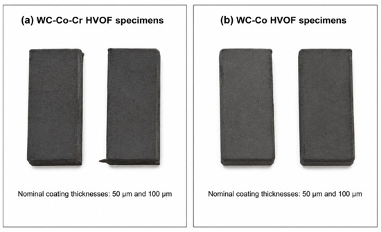
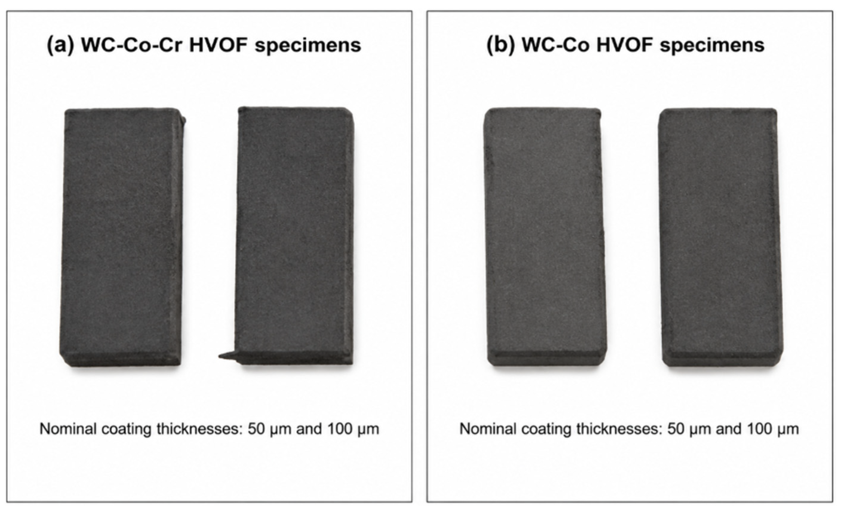
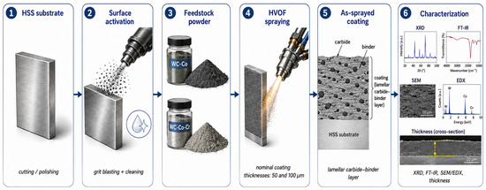
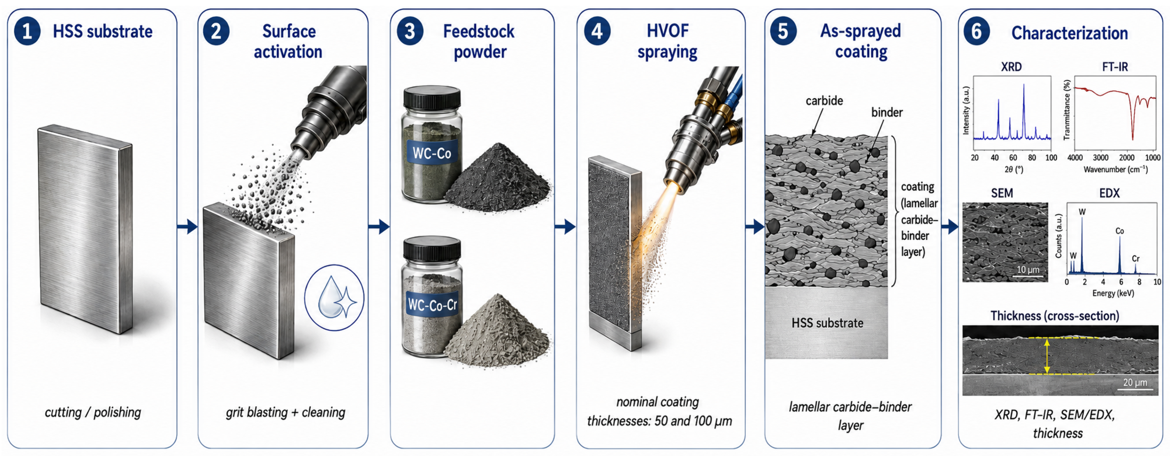
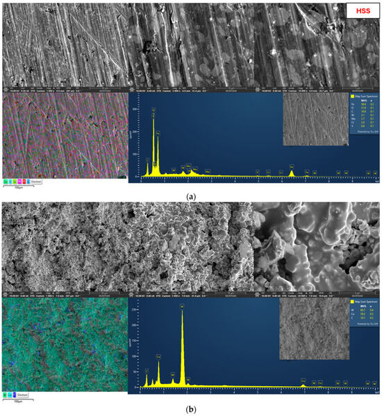
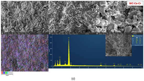
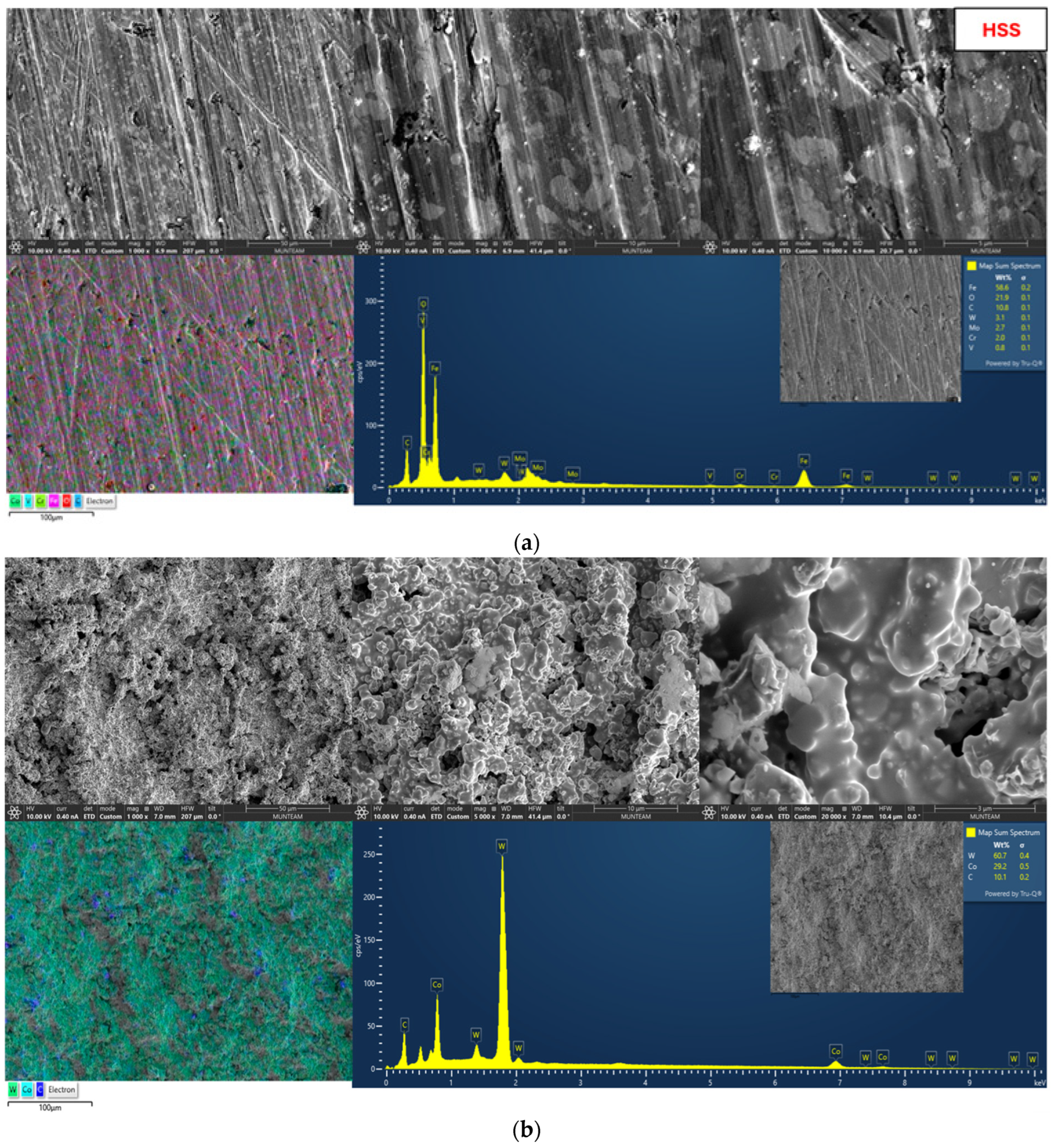
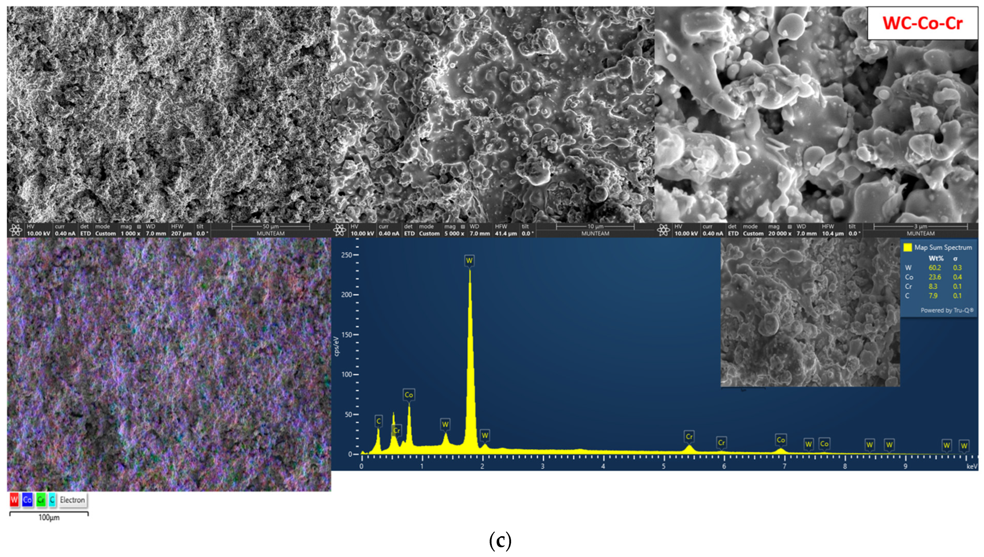
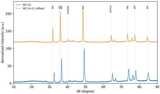
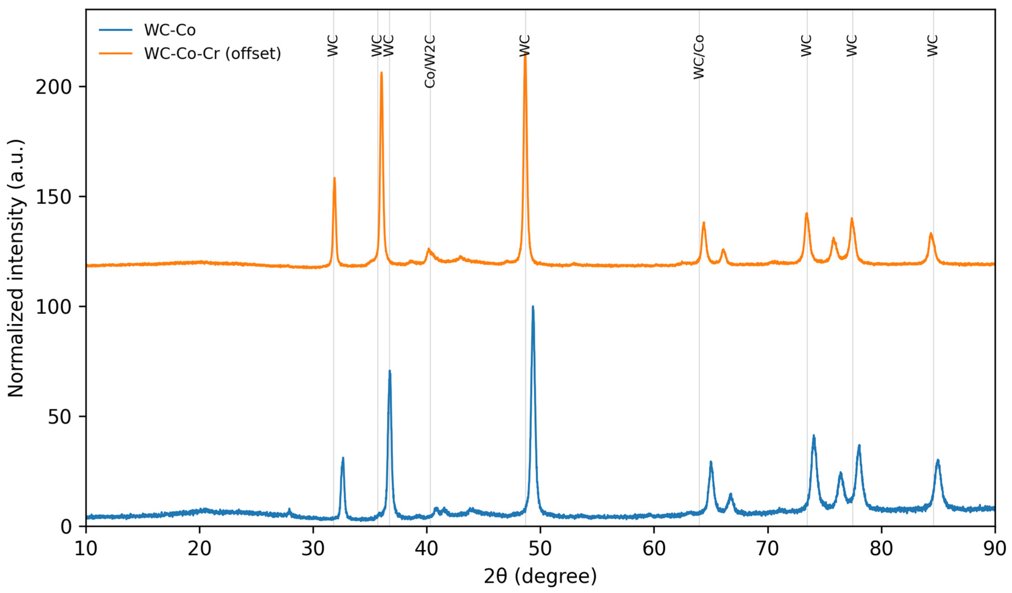
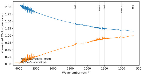
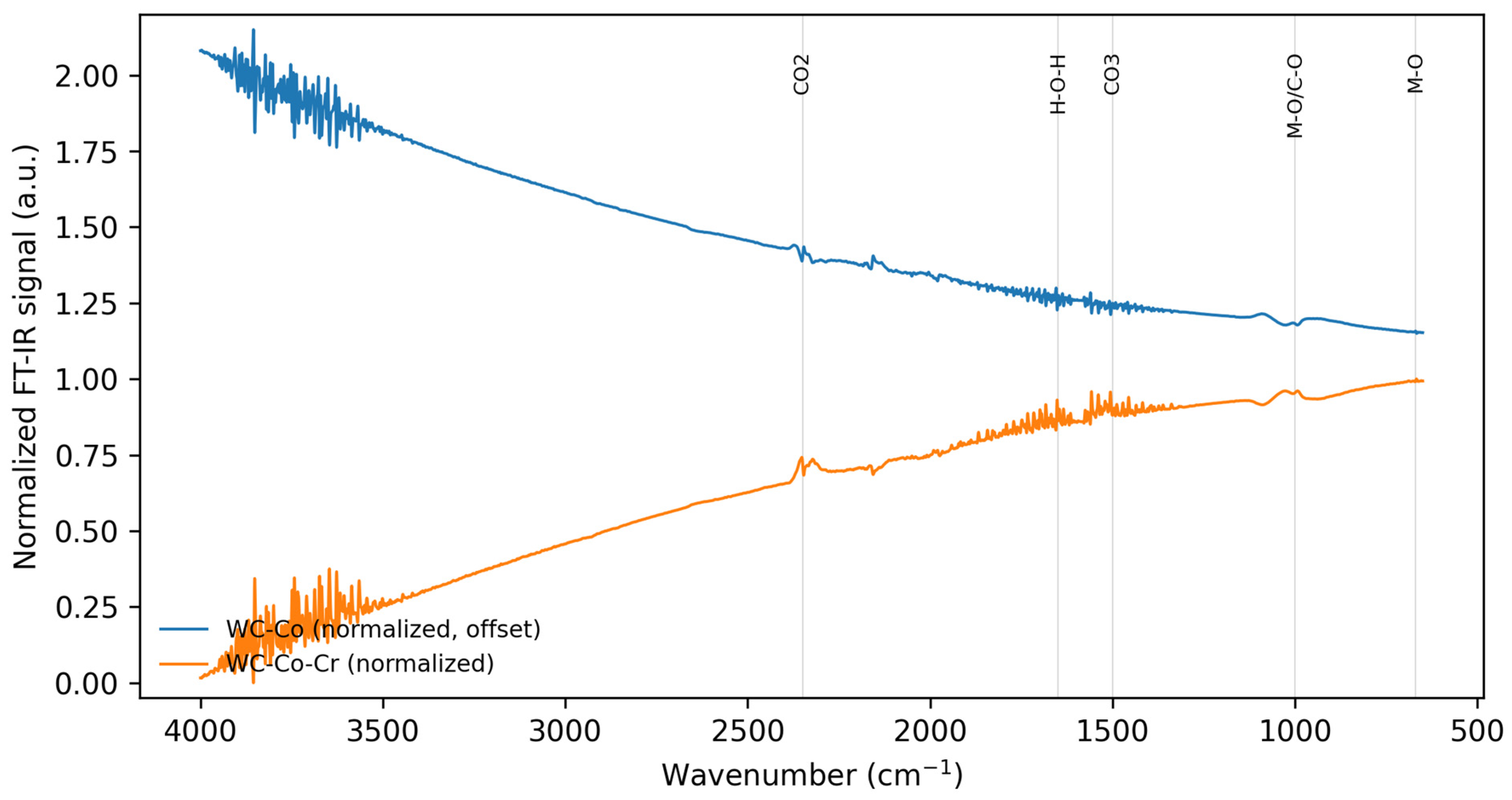
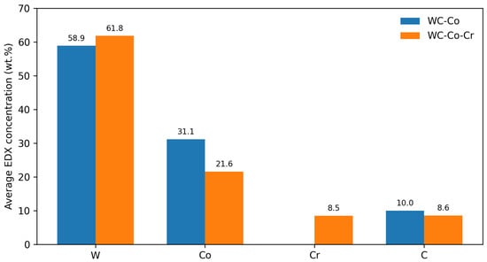
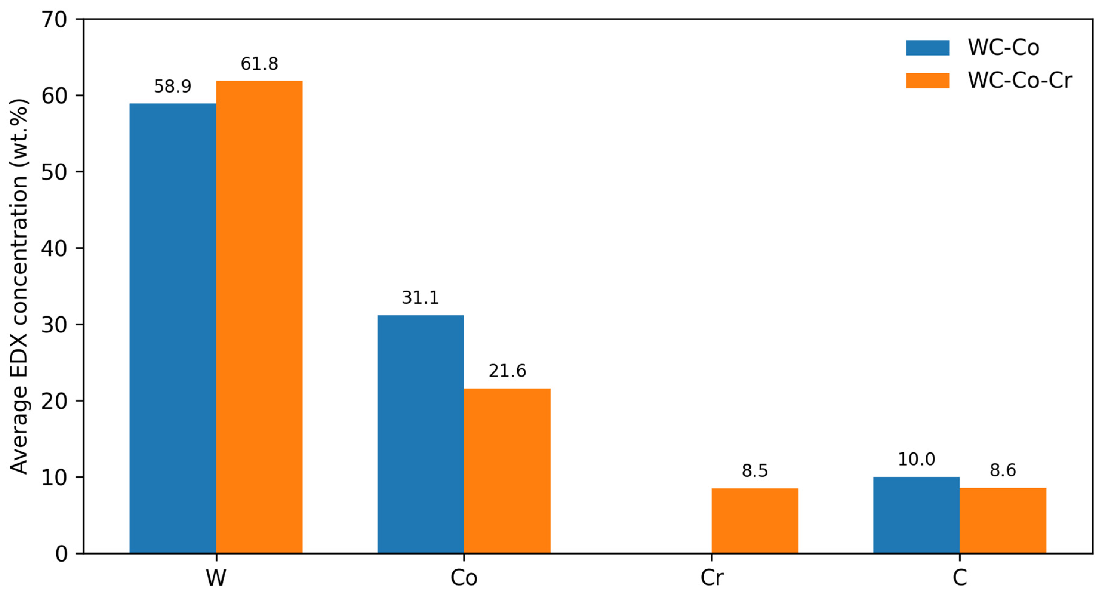
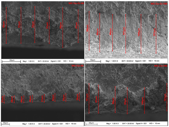
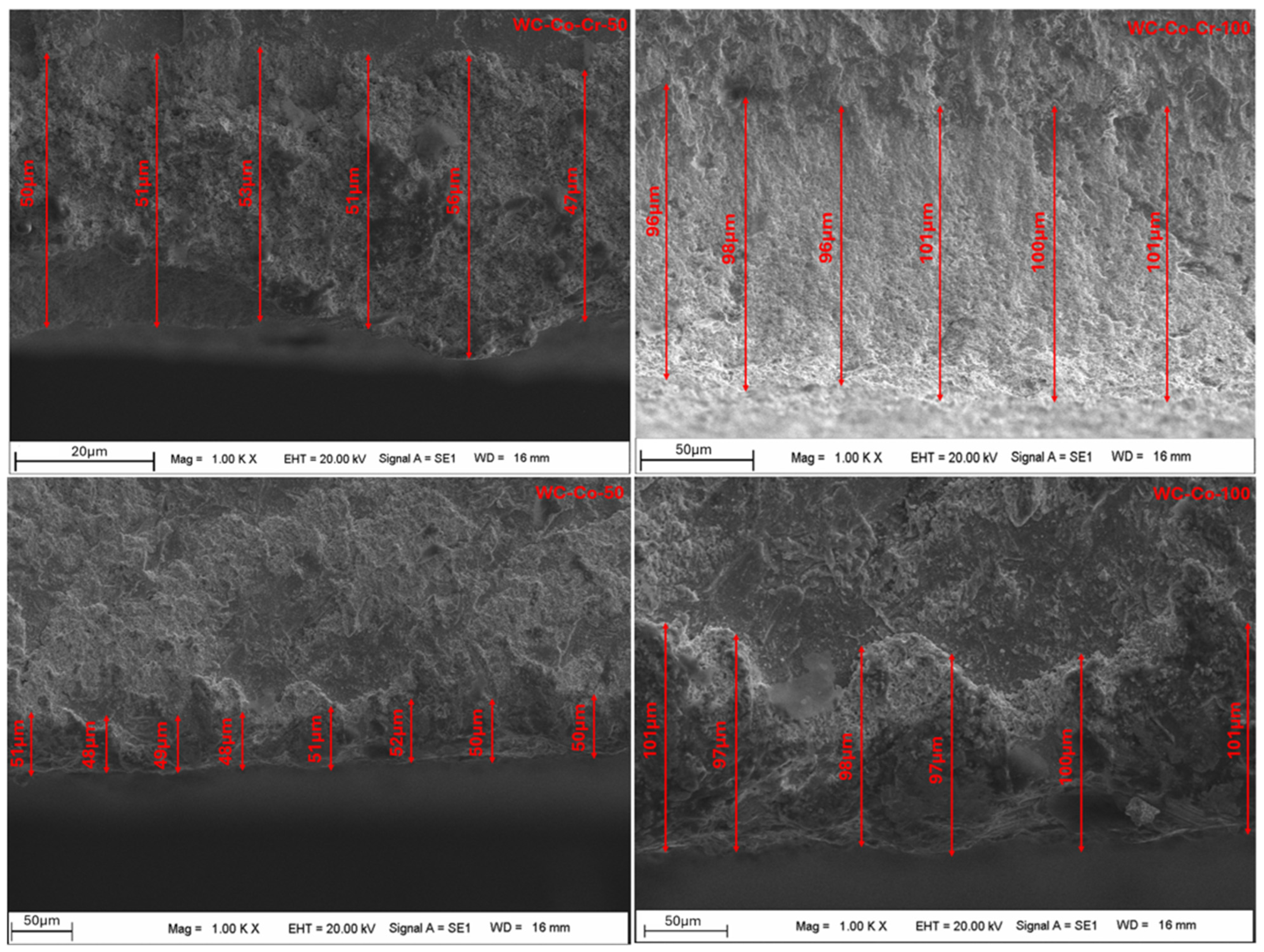
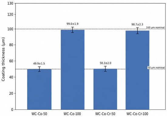
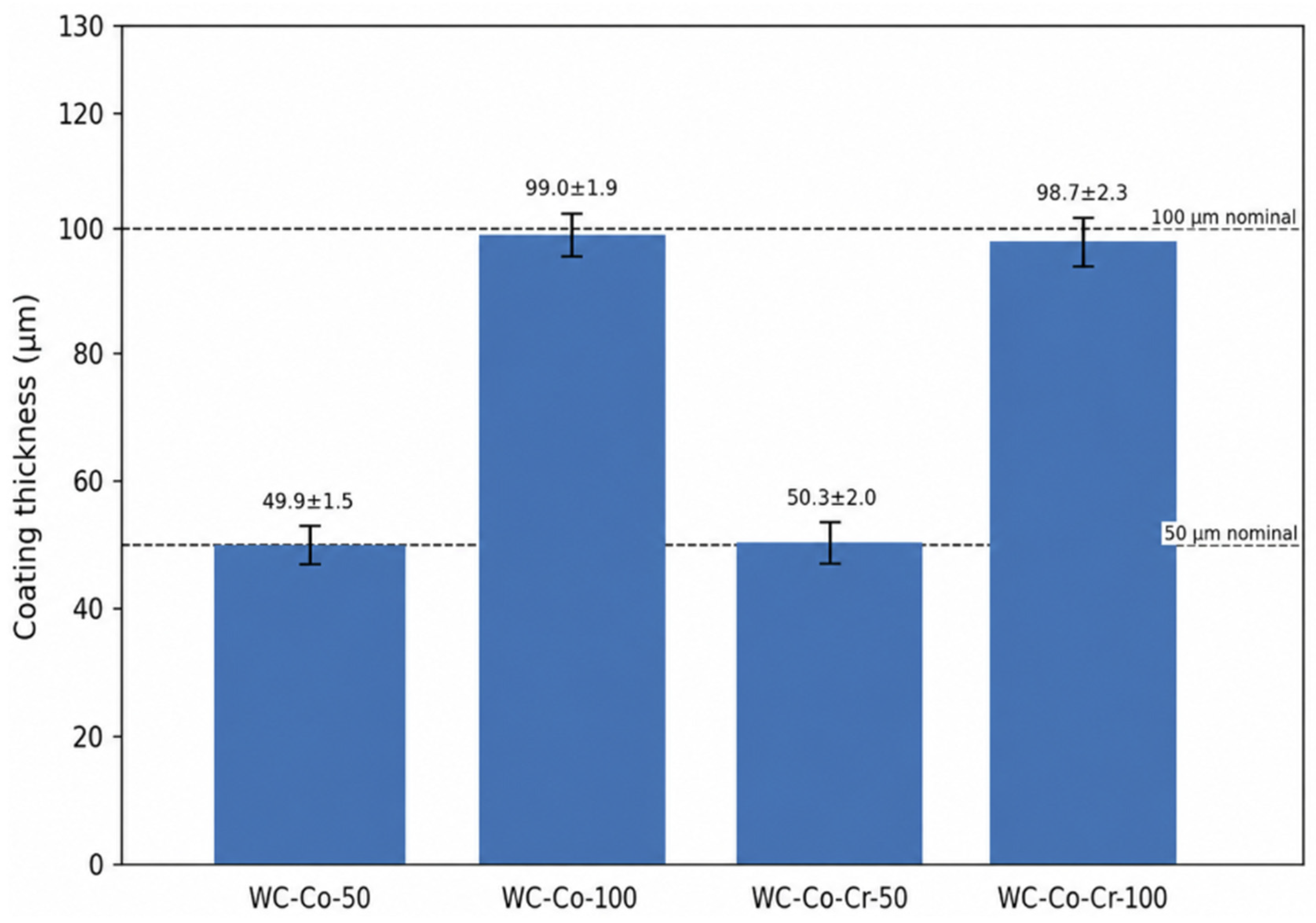
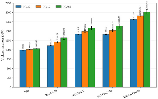
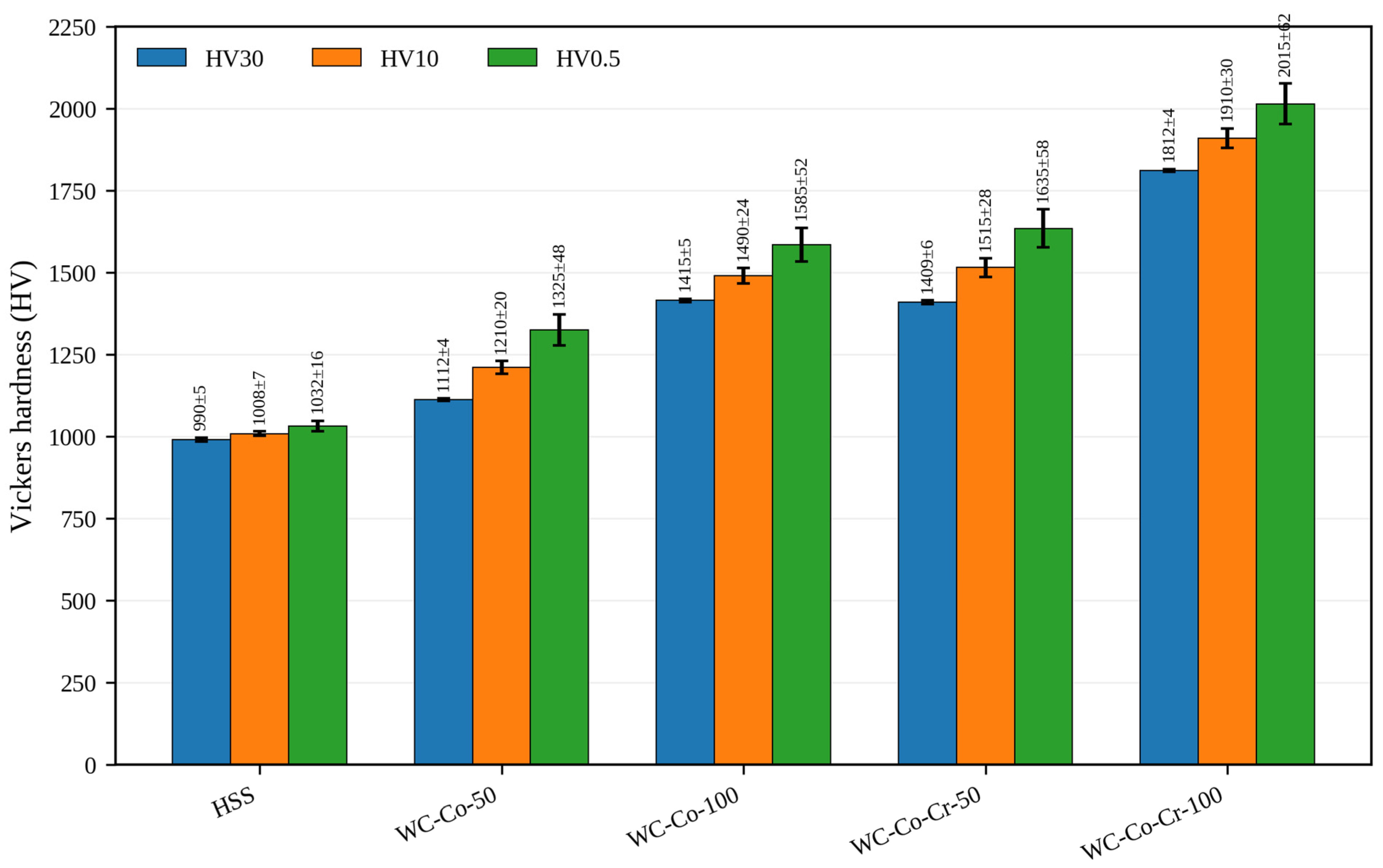
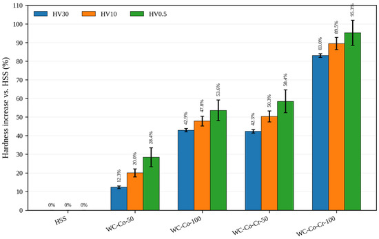
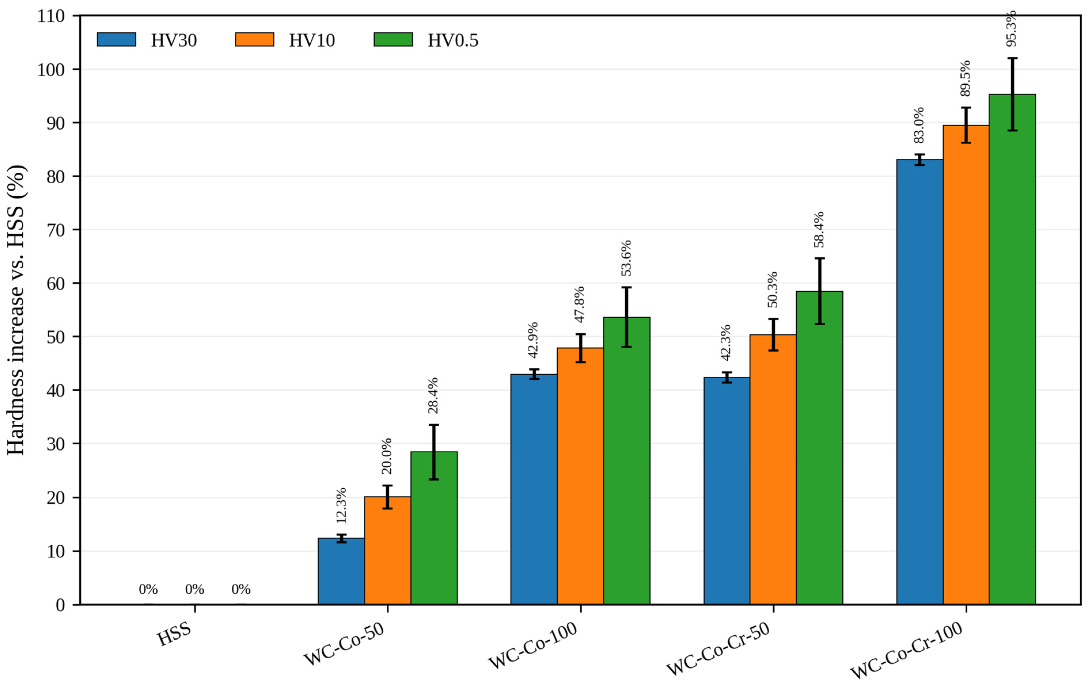
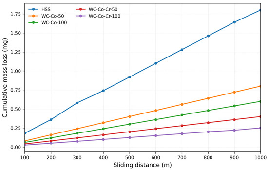
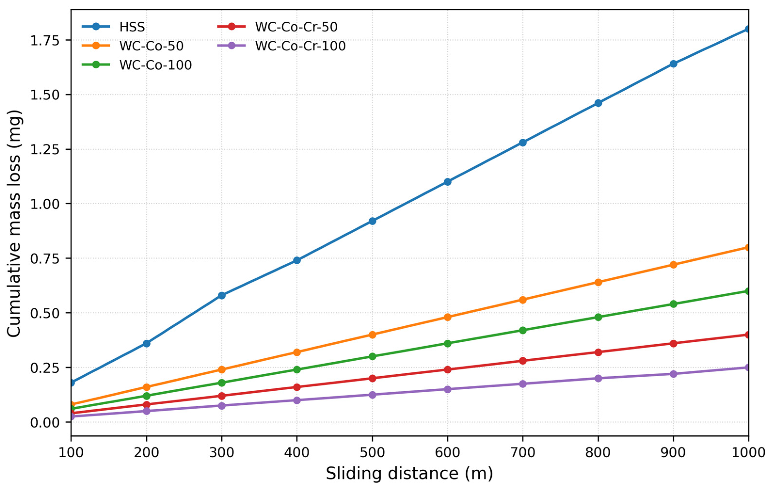
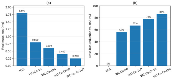
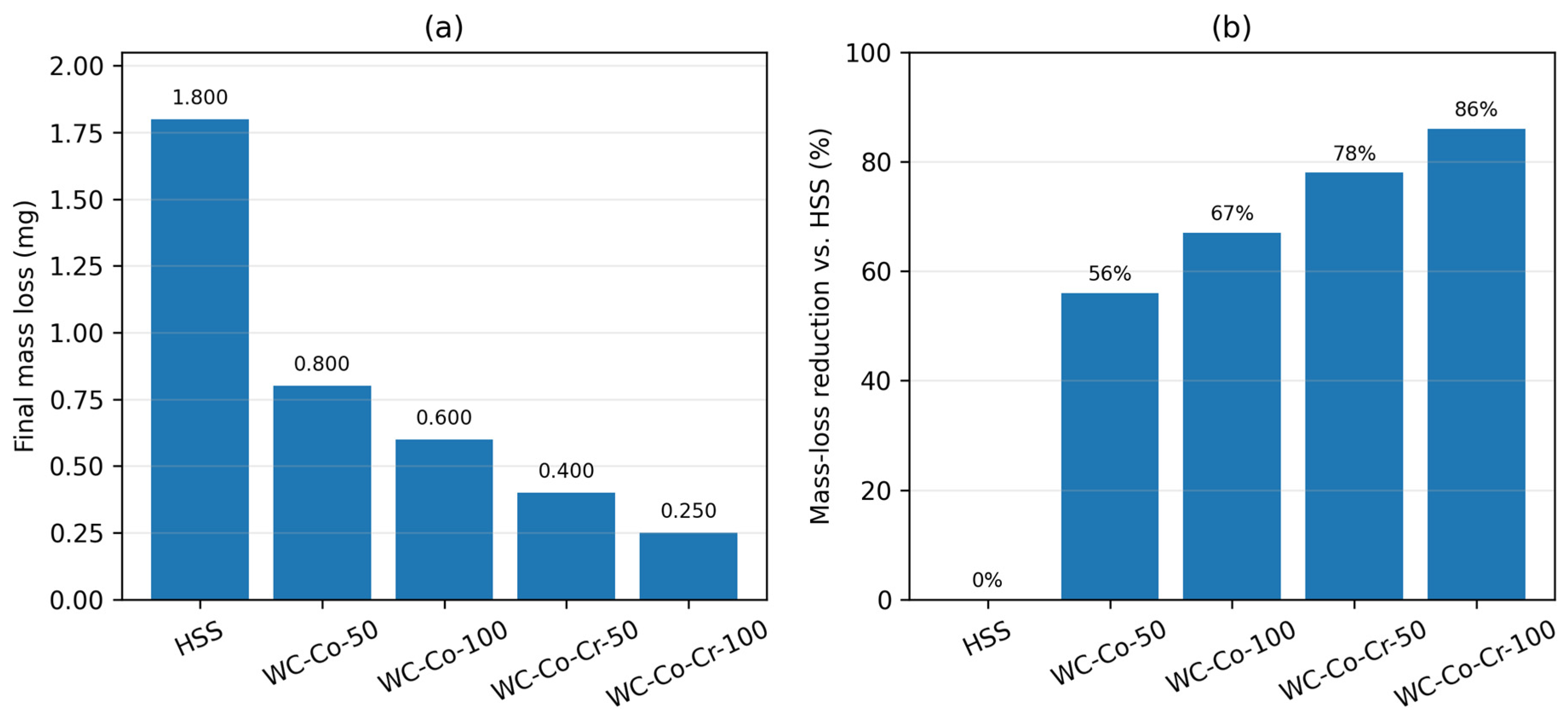
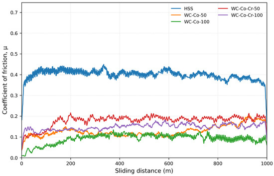
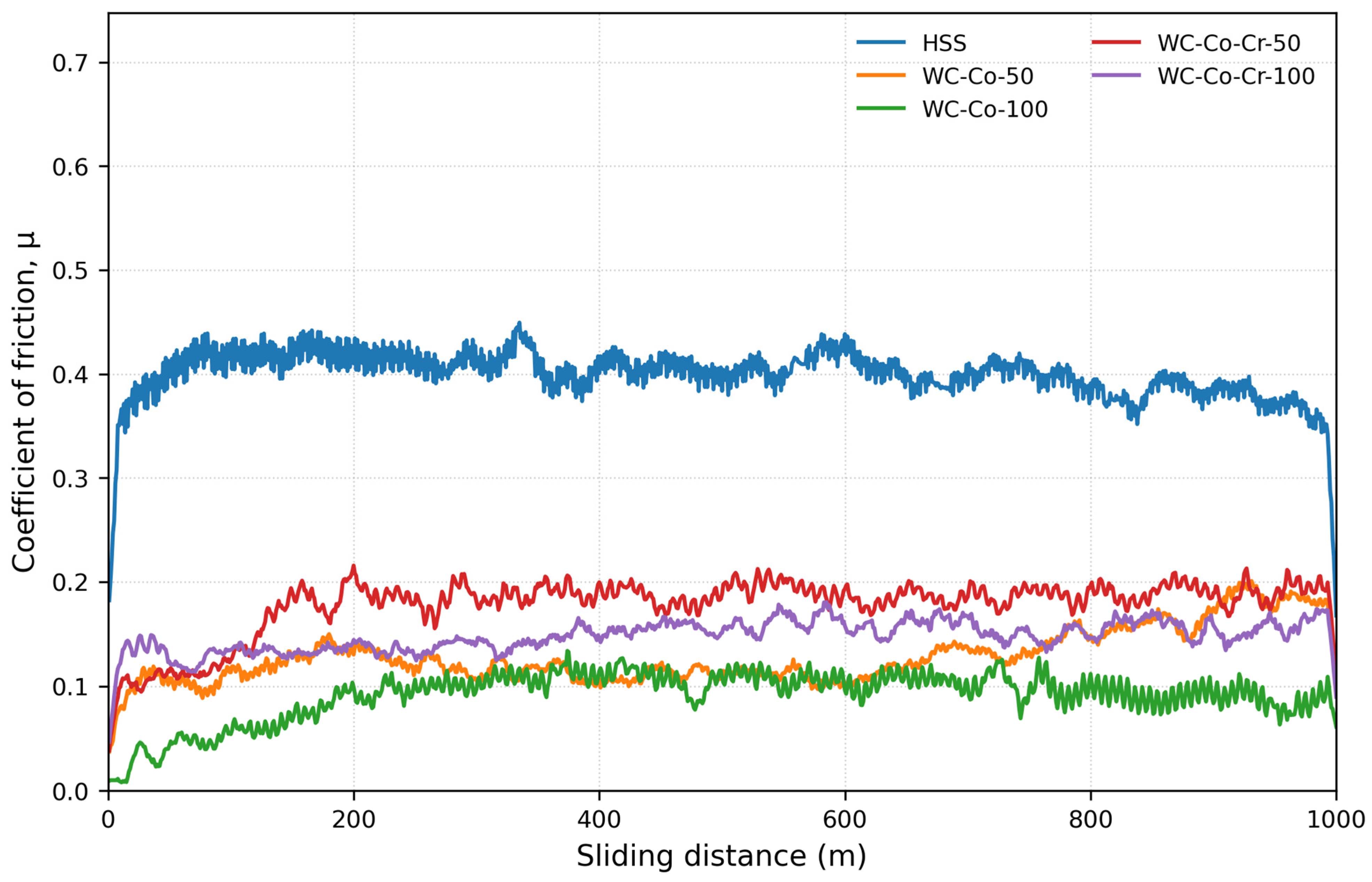
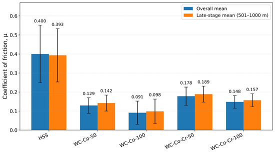
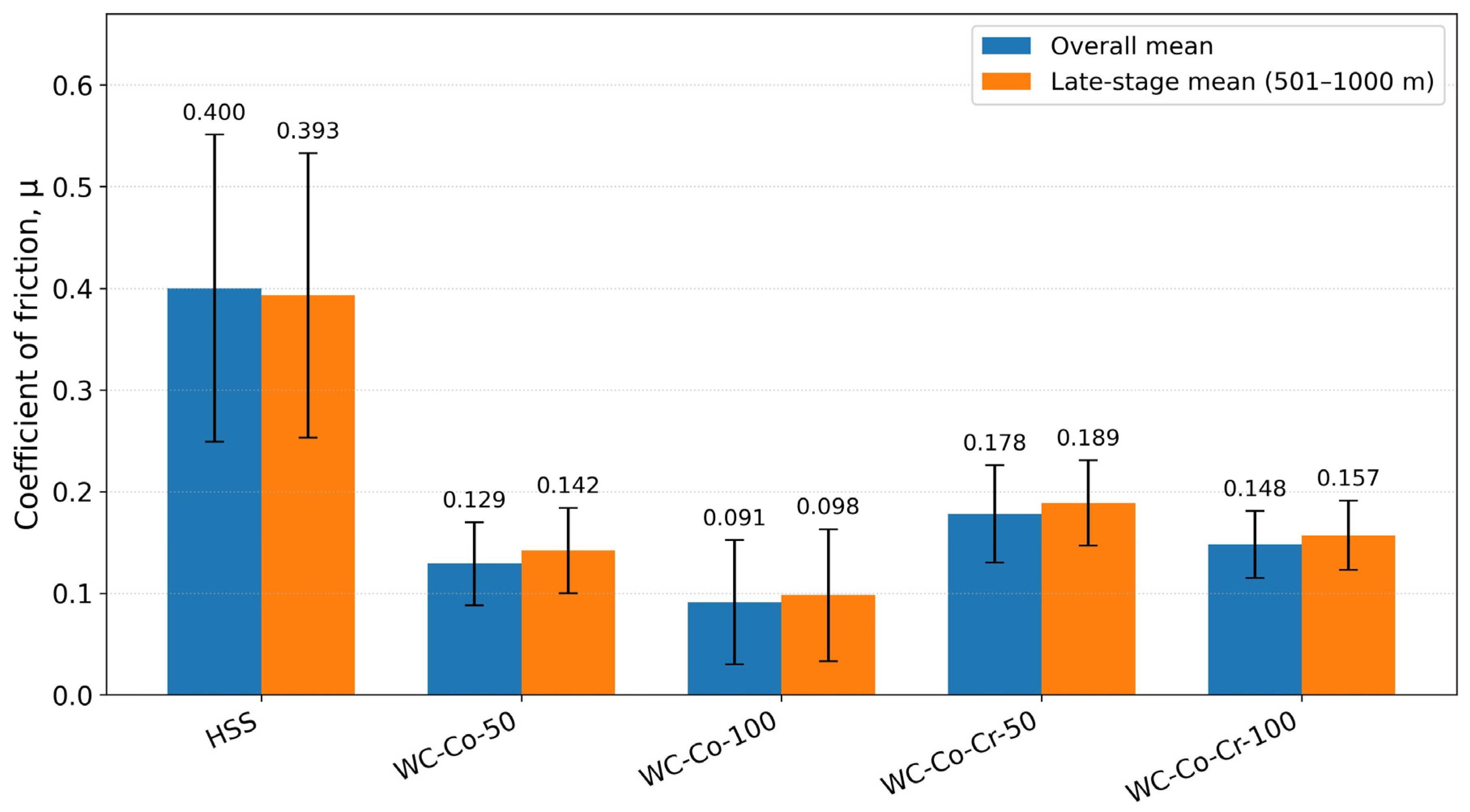
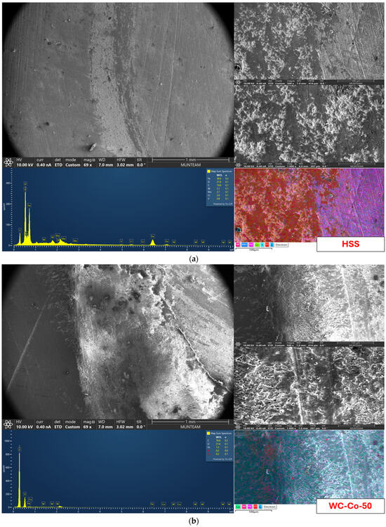
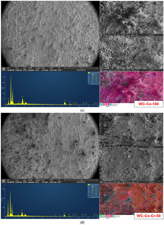
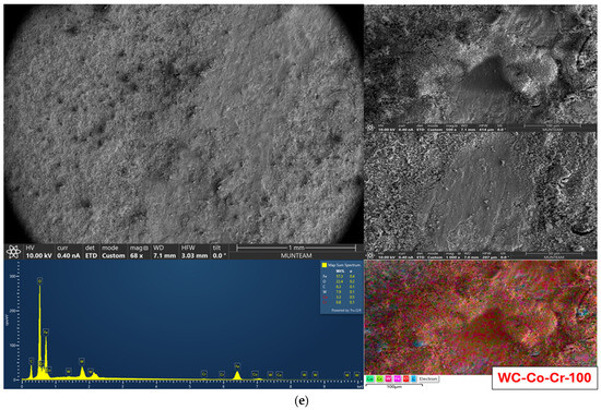
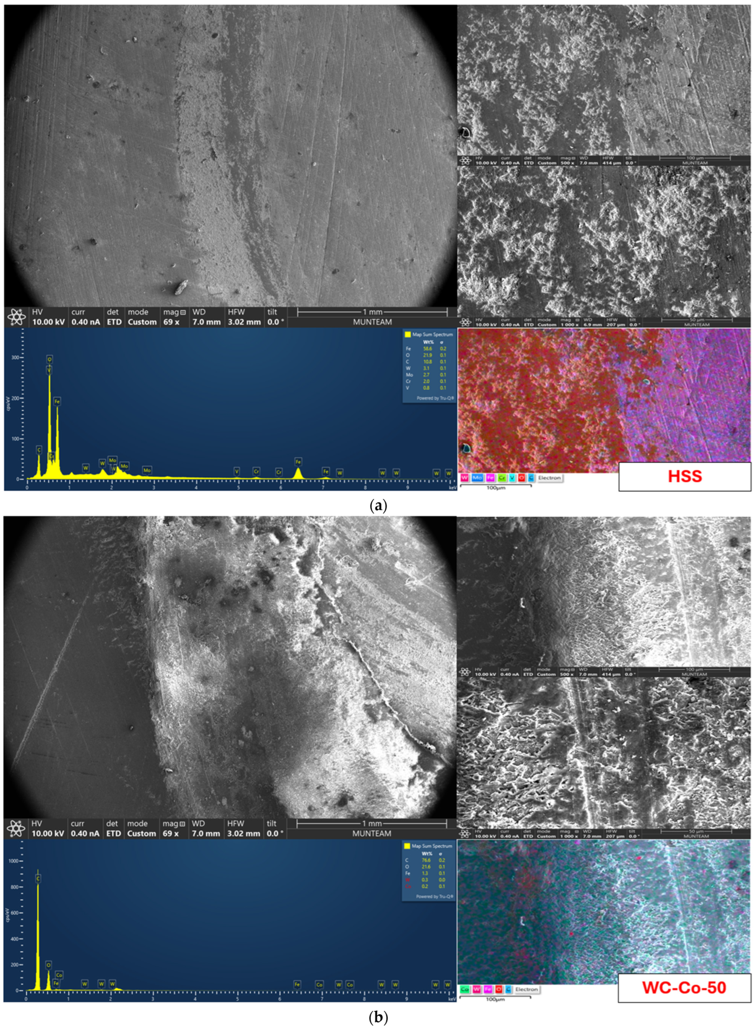
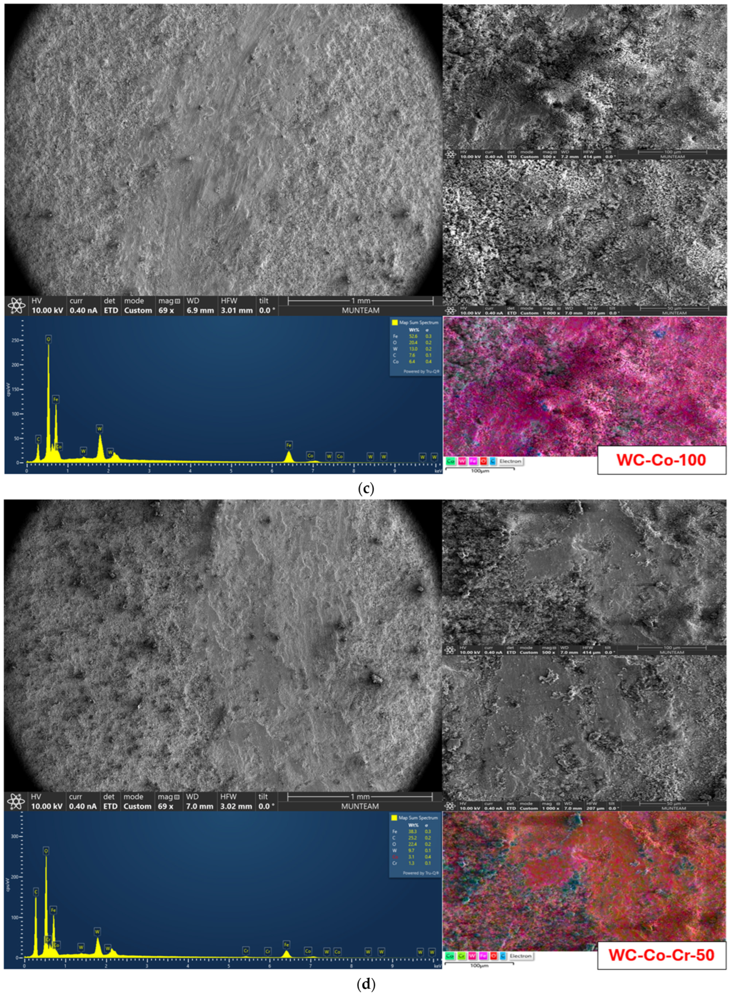
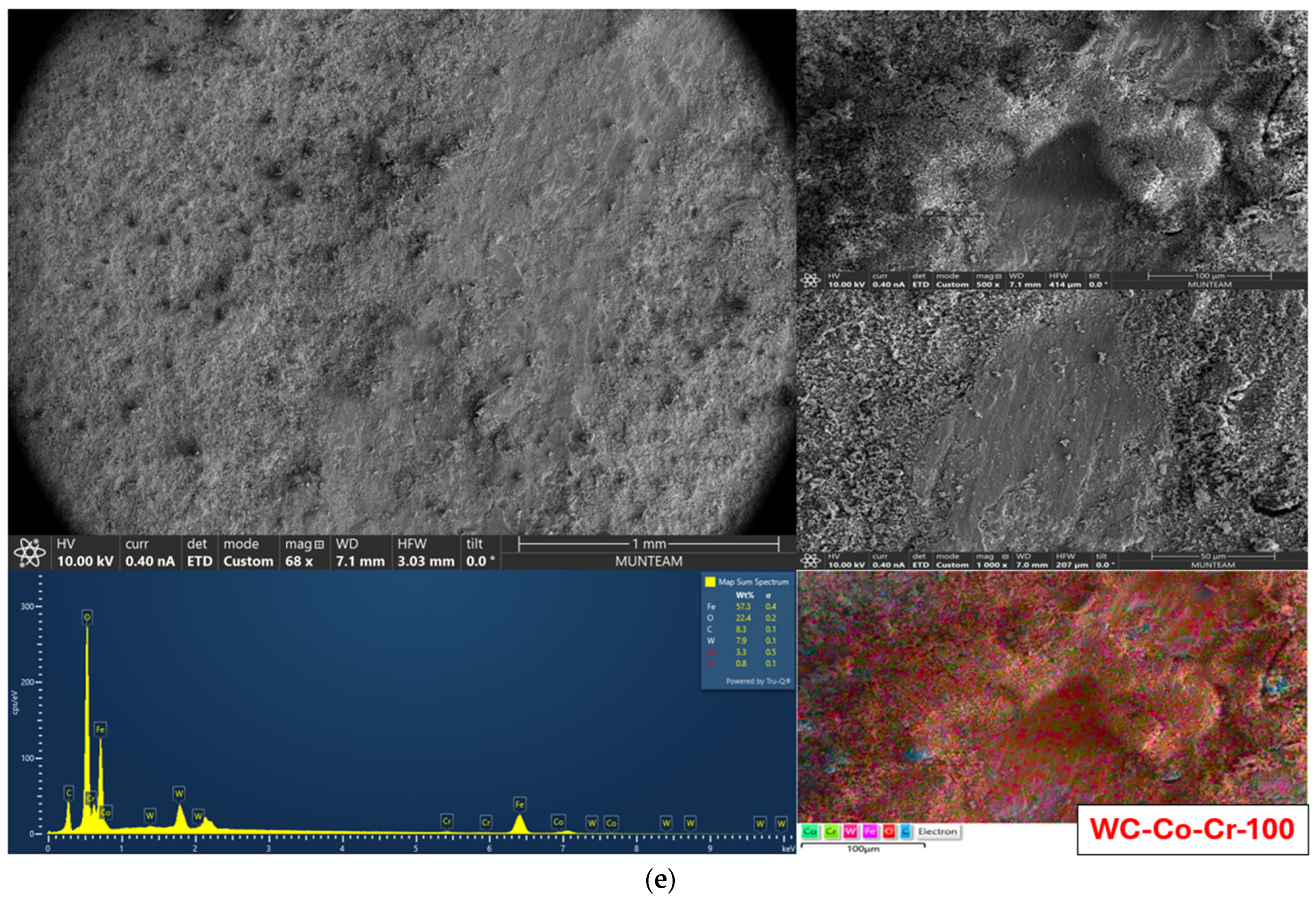

Disclaimer/Publisher’s Note: The statements, opinions and data contained in all publications are solely those of the individual author(s) and contributor(s) and not of MDPI and/or the editor(s). MDPI and/or the editor(s) disclaim responsibility for any injury to people or property resulting from any ideas, methods, instructions or products referred to in the content. |
© 2026 by the authors. Licensee MDPI, Basel, Switzerland. This article is an open access article distributed under the terms and conditions of the Creative Commons Attribution (CC BY) license.