


Abstract
A novel sodium-oxide-fluxed slag is applied in the aluminothermic reduction of manganese ore. The slag’s high Al2O3 solubility facilitates the recycling of Al2O3 through hydrometallurgical processes, where NaAlO2 serves as a water-leachable compound. Aluminothermic reduction is gaining renewed interest as an alternative processing route for the circular economy. In addition, CO2 emissions in aluminium production via the electrochemical Hall–Héroult process can be reduced if the process electricity is sourced from non-fossil fuels. The unique Na2O-fluxed MnO2 ore formulation includes a small quantity of carbon reductant to ensure rapid pre-reduction to MnO. This approach negates the need for a pre-roasting step. Feed mixture variations with different collector metal additions (Si, Cr, Cu) were made to improve alloy–slag separation efficiency. The collector metals may influence the chemistry of the slag. This work compares the phase chemistry of slags formed during aluminothermic reduction to equilibrium phase chemistries calculated for the Na2O-SiO2-Al2O3-MnO-CaO system. The slag phase morphology consists of distinct alumina-rich strands (1.5% to 2.1%) embedded within a Na2O-SiO2-Al2O3-MnO-CaO glass matrix. The alumina-rich strands appear molten, indicating that the processing temperatures were higher than their liquidus temperatures (1537 °C to 1655 °C), as high as 1921 °C and 2053 °C. These findings contribute to sustainable practices in the circular economy through the production of low-carbon ferro-manganese complex alloys.
Keywords:
aluminothermic; thermochemistry; alumina; sodium-oxide; manganese ore; ferroalloy; slag; circular economy 1. Introduction
Aluminothermic reduction in oxides is a well-established method of reducing oxides in the production of low-carbon ferroalloys, such as ferromanganese and ferrochromium [1,2]. This processing method is gaining renewed interest because aluminium as a reductant opens the possibility of a circular process with reduced CO2 emissions as proposed in recent studies [3,4,5,6,7,8]. Aluminium is produced electrochemically in the Hall–Héroult process, and if the electricity is generated from non-carbon energy sources, most of the CO2 formation in the process can be negated. Recent work has applied discarded smelter slag as the MnO source in aluminothermic reduction, since much MnO slag is stockpiled [4,5]. However, these slags are currently produced as by-products or discard products of carbothermic reduction processes, and the aluminothermic reduction process requires additional heat supplied via an electric furnace [3,4,5,6,7,8]. This method of aluminothermic reduction is the ASR (aluminothermic smelting reduction) method in which a slag layer is reacted in contact with a molten aluminium layer [9]. The reactants are contained in a furnace which is supplied with external heating, in addition to the exothermic heat from aluminothermic reactions. In contrast, the application of aluminothermic reduction, using ore as the starting material, can provide a simplified, single-step circular process that eliminates the need for an electric furnace. Aluminothermy via the SHS (self-propagating high-temperature synthesis) method [10,11] is used to produce low-carbon ferromanganese from pre-roasted MnO2-type ore [12]. Ore pre-roasting is required to convert MnO2 to Mn2O3 or Mn3O4, thereby decreasing the violent heat release during aluminothermic reduction of MnO2 [12]. The ore feed requirements are a minimum Mn content of 46% and a Mn/Fe ratio of 9, with P < 0.12%. CaF2 is added as a flux. The product alloy composition ranged from 70% to 84% Mn, 13% to 16% Fe, 1% to 10% Si, <0.03% Al, and <0.24% P, with an alloy yield of 58% to 64% [12]. Therefore, a significant quantity of material is lost to the gas phase, and possibly also to the slag phase. Encapsulation of the reactant aluminium was reported in the application of the SHS method to SiO2-MnO2-Fe-Al mixtures [13]. It is well documented that reactant particle size is critical to the achieved temperature and product metal yield in the SHS processing method [10]. Reaction of hematite–Al thermite mixtures easily result in temperatures of 2000 °C to 3000 °C [10]. Chemical equilibrium is unlikely under SHS process conditions because rapid heat release from the exothermic reactions provides a short reaction time and limits the time available for product diffusion to form homogenous molten phases [11]. Precise balancing of the required aluminium addition without excessive aluminium uptake in the product alloy is typically determined empirically [14,15,16,17,18].
The effective separation of the alloy from the slag determines the overall yield of the aluminothermic reduction process. Alumina has a high melting point (2053 °C). Therefore, a high-alumina slag can be problematic due to insufficient fluidity, which hinders alloy separation from the slag. Thus, the slag chemistry must be designed to flux most Al2O3 whilst aiming for a low slag volume. Circular processing of aluminium via alumina recovery requires suitable slag phase chemistry for subsequent hydrometallurgical recovery of Al2O3 [4,5,19]. Since CaO and Al2O3 form low liquidus compounds and CaO in the slag increases the activity of MnO in the slag to promote aluminothermic reduction of MnO, the aim slag of CaO-Al2O3 was applied [4,5]. The leaching of Al from CaO-Al2O3 slag has been demonstrated in a 10% Na2CO3 solution, reacted at 30–45 °C for 90 min, resulting in 90.5% Al leached [19]. Only a small quantity of the silicate phase was not leachable. The leaching process is diffusion-limited for both aqueous reactants and products in the leaching reaction, forming the aqueous NaAlO2 compound. Calcite precipitation onto the slag surface may interfere with the leaching process, but increased stirring and wet-grinding leaching techniques can mitigate this effect.
Another approach is to form a Na2O-Al2O3-based slag, since the NaAlO2 compound is readily leached by water at 60 °C, resulting in 80% Al leached in 60 min at 1:10 solid–liquid ratio [20]. Leachate carbonation was applied at 80 °C by bubbling 25 L/h CO2 gas through the solution at pH of 10.5–12.5 to recover 96.5% Al as α-Al(OH)3 (Bayerite) at 98.8% alumina grade. The Bayerite particles were sized at 90% + 44 μm, to form suitable feed for the Hall–Héroult process, following calcination to α-Al2O3 [20]. Therefore, it appears that pre-forming the water-soluble NaAlO2 compound negates the leaching-stage diffusion limitations found in Na2CO3-based leaching of CaO-Al2O3 slag. The thermochemistry of the reactor lining also drives flux selection. Sodium-oxide is highly corrosive to traditional refractory materials such as MgO and Al2O3. Therefore, using the Na2O fluxing option in the ASR process, in a furnace arrangement, would likely require speciality refractories such as SiC. Application of CaO as flux negates this problem since the CaO-Al2O3 is not highly corrosive. Theoretically, an Al2O3 refractory lining can be used if the slag is Al2O3 saturated at the attained slag temperature. Such an Al2O3-saturated slag chemistry in the Na2O-Al2O3-based slag is considered in this work. In addition, in the case of the SHS process option with shorter melt-refractory contact times rather than in the ASR furnace-based process, the use of graphite should be adequate [14,15].
The authors’ recent work illustrates the application of a sodium-oxide fluxed high-alumina slag in the one-step aluminothermic reduction of MnO2 ore. Different collector metals were applied to improve metal separation from the slag [16,17,18]. A small quantity of coal was added to pre-reduce the ore to MnO, thereby negating the need for a pre-roasting step. The bulk slag was previously considered for mass-balance purposes and to gauge whether the target slag was reached. Therefore, only in this study is the detailed slag phase chemistry reported and investigated. One way to estimate the attained process temperatures is to compare the phase chemistry of the product slag to the expected equilibrium phase chemistry from phase diagrams. Therefore, this work describes the design and characterisation of a suitable sodium-oxide-fluxed slag for the circular processing of aluminium as the primary reductant in manganese ore aluminothermy to form low-carbon ferro-manganese complex alloys. Thermochemical software (FactSage 7.3) is used to investigate the phase chemistry of slags produced by aluminothermic reduction of manganese ore. The thermochemical calculations are crucial since the Na2O-SiO2-Al2O3-MnO-CaO phase relations at the high temperatures of aluminothermic reduction are not experimentally available.
2. Materials and Methods
2.1. Materials
The reaction mixture consisted of manganese ore, coal, lime and sodium silicate as flux, and metal powders of aluminium and individual tested collector metals (silicon, chromium, copper). The chemically pure metal powders were sourced as follows: Al (99.7% Al, −1 mm) and Si (99.9% Si, −44 µm) provided by Sigma-Aldrich (Johannesburg, South Africa), Cr (99.0% Cr, −44 µm) and Cu (99.8% Cu, −200 µm) supplied by Alfa Aesar (Johannesburg, South Africa). The chemically pure sodium silicate is supplied by Sigma-Aldrich (Johannesburg, South Africa), and CaO is provided by Associated Chemical Enterprises (Johannesburg, South Africa). The manganese ore is a pyrolusite (MnO2)-based ore sourced from a small-scale ore body complex in South Africa, and the medium-volatile coal is also sourced from South Africa. The composition of the manganese ore and coal ash is shown in Table 1. The coal contains 22.5% volatile matter, 12% ash, 62.2% fixed carbon, and 3.3% moisture. The mixture, based on 100 g of ore, was placed in a graphite crucible and sealed with a graphite lid. The crucible dimensions were 50 mm inner diameter, 70 mm in height, and 7 mm in wall thickness. The lid was recessed by 7 mm to fit the crucible’s inner diameter. The reaction mixtures are summarised in Table 2.
Table 1.
Bulk chemical composition of manganese ore and coal ash (mass%).
Table 2.
Reaction mixtures (grams).
Collector metal selection is mainly based in the oxygen affinity of copper, silicon and chromium, relative to that of manganese. Similar to aluminothermic reduction, silicon is used to reduce MnO in silicothermic reduction, but additional heat is required to drive the process to completion [1]. Silicon is expected to assist in maintaining reducing conditions in the reaction mixture to improve alloy yield [16]. Chromium has a lower oxygen affinity than manganese, but can also lower the system partial oxygen pressure, similar to the effect of silicon [17]. Copper has low oxygen affinity, and its role as collector metal is due to adding coalescence sites for newly formed iron and manganese. The activity of manganese metal is lowered by copper, so that the aluminothermic reduction reaction is forced to the product side [18]. Silicon collector metal also lowers the solubility of carbon in the Fe-Mn alloy, so restricting carbon pick-up from the graphite crucible [16]. Lower carbon content ferro-manganese complex alloys are sold at higher prices than high-carbon alloys [1,2].
2.2. Methods
The reaction mixture was weighed and thoroughly mixed in a mixing container. The mixture was transferred into the graphite crucible, and the graphite lid was placed onto the crucible rim. The muffle furnace was pre-heated and soaked for 12 h at the set-point temperature of 1350 °C. The furnace temperature was controlled using a proportional-integral-derivative (PID) controller. The aluminothermic reaction consists of placing the graphite crucible and contents into the muffle furnace. From prior experimentation, it was noted that the crucible must be removed from the furnace 2 min after ignition, as indicated by a flash flame exiting the muffle furnace’s top panel joint gaps. Therefore, the reaction mixture was not entirely heated by the muffle furnace, but rather via the exothermic aluminium (aluminothermic) reactions. The ignition time was 6 min after the crucible was placed in the furnace. Following a total reaction time of 8 min, the crucible and its contents were removed from the furnace. The lid was then removed, and the fluid metal and slag were poured into a cast-iron mould. Upon cooling to room temperature, the poured contents were returned to the graphite crucible for manual separation of metal and slag, followed by subsequent mass measurements.
The large slag and alloy volumes were sectioned for chemical analysis of the slag phase using a scanning electron microscope (SEM). The cross-section faces were coated with gold for analysis by SEM using a Zeiss 540 Ultra FEG (field-emission gun) SEM (Zeiss, Oberkochen, Germany) with an energy-dispersive spectroscopy (EDS) probe, operated at 20 kV. FactSage 7.3 thermochemical software is used to calculate the equilibrium phase chemistry of the target and experimentally generated slag compositions [21]. Thermochemical calculations were made in the Equilib and Phase diagram modules of FactSage using database selections of FToxid, SGTE and FactPS. The adiabatic temperature of each feed mixture was calculated in the Equilib module by using the gas–slag–metal equilibrium simulation calculation as described in [21].
The area percentage of alumina-rich strands was measured by applying ImageJ software (version 1.54s) [22] to the SEM-EDS aluminium element map of each analysed area. Each image was adjusted for brightness to enhance the identification of alumina-rich strands. The image was then converted to 8-bit grayscale, the threshold set to identify the alumina-rich strands from the matrix phase. The image was processed into a binary outline and then analysed for particles larger than 200 pixels.
3. Results and Discussion
Aluminothermic reduction proceeds rapidly, releasing significant excess heat, making it difficult to predict the end-point chemistry of the product alloy and the slag. The slag samples from each feed mixture were analysed by SEM-EDS to facilitate interpretation of the achieved slag phase chemistry relative to the targeted slag phase chemistry. SEM-EDS areas of 0.25 × 0.78 mm were analysed as element maps, with some instances where smaller specific phase areas were examined. Aluminothermic reactions occur at significantly higher temperatures, reaching as high as 3000 °C, compared to the average temperatures in conventional alloy processing [10]. These high average temperatures should bring the process close to equilibrium, but the heat release time is short, so equilibrium is unlikely [10,11]. Despite non-equilibrium conditions prevailing, calculating equilibrium phase chemistries can yield valuable insights when compared with experimental measurements. This approach is followed in the next section, where FactSage 7.3 thermochemical software is used to calculate the expected slag phase chemistries [21]. These equilibrium values are then compared with the SEM-analysed values to interpret the experimental observations.
3.1. Target Slag
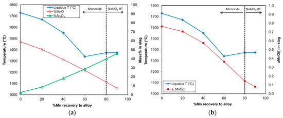
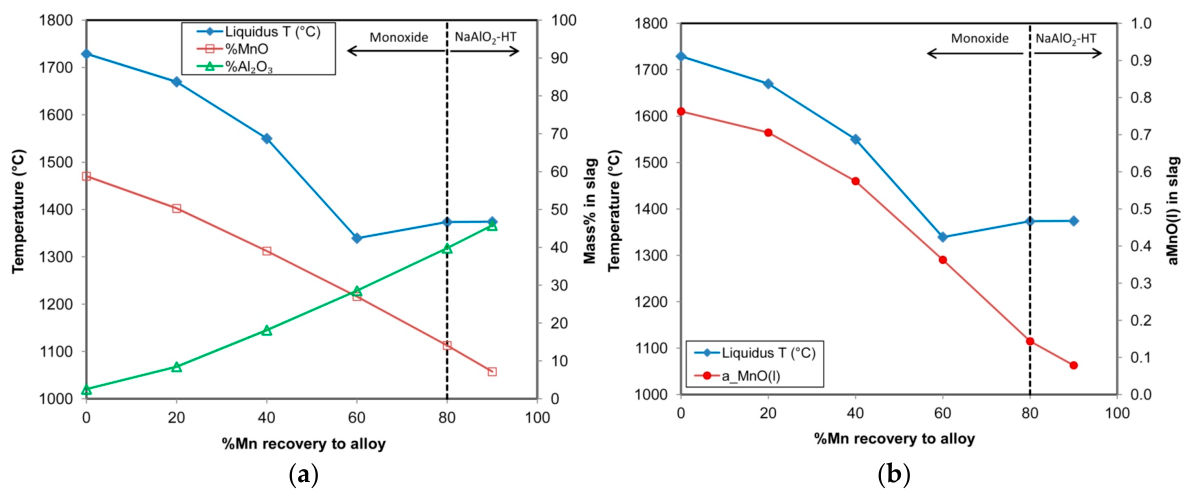
The target slag chemistry was designed to dissolve most of the alumina produced in the aluminothermic reduction of manganese and iron oxides in the manganese ore by adding sodium-oxide flux. Sodium-oxide addition is required to form the desired NaAlO2 compound for hydrometallurgical processing to recover aluminium. Sodium-oxide was added as Na2O.SiO2. The slag basicity of B2, defined as (%CaO)/(%SiO2), is targeted at 1.0 to facilitate high MnO activity if MnO dissolves into the glass phase. It is possible that the reduction in the MnO2 ore proceeds initially without much slag formation since the ore contains limited slag formation components, such as 5% SiO2 and 3% Al2O3. In this scenario, the MnO of high melting point (1842 °C) is at its maximum activity value of 1. However, considering the feed mixture as a single melt, the bulk slag liquidus temperature and the activity of MnO in the melt were calculated as a function of varying MnO content. The bulk slag’s decreasing MnO content, accompanied by an increase in the Al2O3 product from aluminothermic reduction via reaction (1), was calculated using a simple mass balance. The results are shown in Figure 1a,b. It is observed that the initial slag liquidus temperature is high at 1729 °C due to 59% MnO initially present in the bulk slag. As aluminium reduces MnO, the percentage of MnO decreases and that of Al2O3 increases, resulting in a decrease in the slag liquidus temperature to 1339 °C (at 60% Mn recovery to the alloy). This slag remains saturated in the monoxide phase, which primarily consists of MnO, with a small amount of CaO in solid solution. The transition from monoxide, the saturation phase, to NaAlO2 occurs in a slag containing 14% MnO and 40% Al2O3, with a liquidus temperature of 1400 °C. The activity of MnO as presented in Figure 1b continuously decreases with MnO reduction to the alloy for the assumption of a single melt feed mixture. The real manganese ore progression is likely more favourable in thermodynamic terms due to high MnO activity at local reduction sites at the start of the reduction reaction, followed by bulk slag formation with low MnO activity.
3(MnO) + 2(Al) = <Al2O3> + 3(Mn)
< > = solid; ( ) = liquid
Figure 1.
(a) Calculated slag composition and liquidus temperature vs. %Mn recovery to alloy; (b). Calculated MnO activity and liquidus temperature vs. %Mn recovery to alloy.
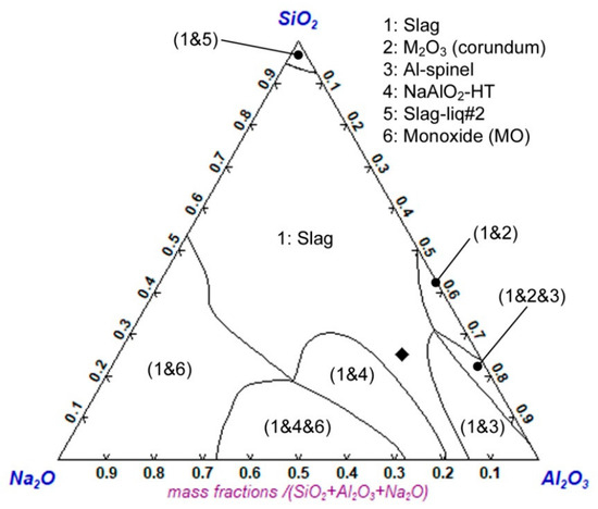
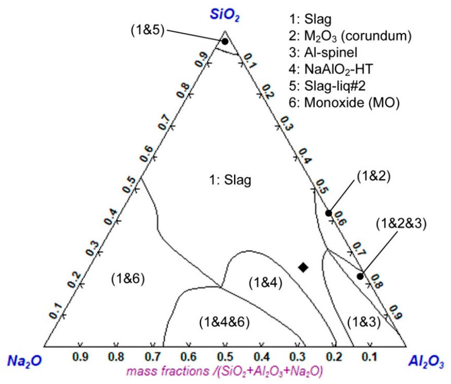
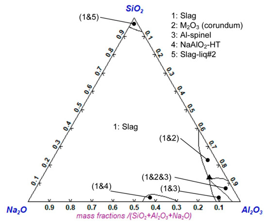
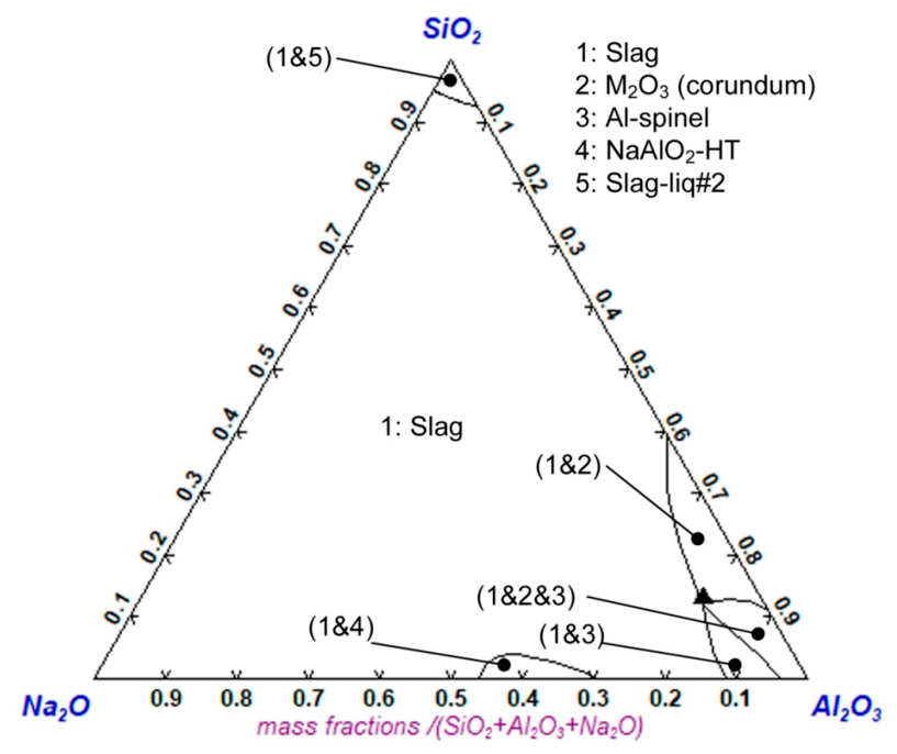
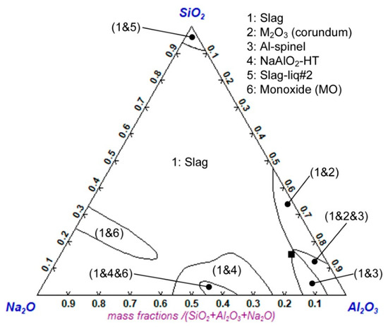
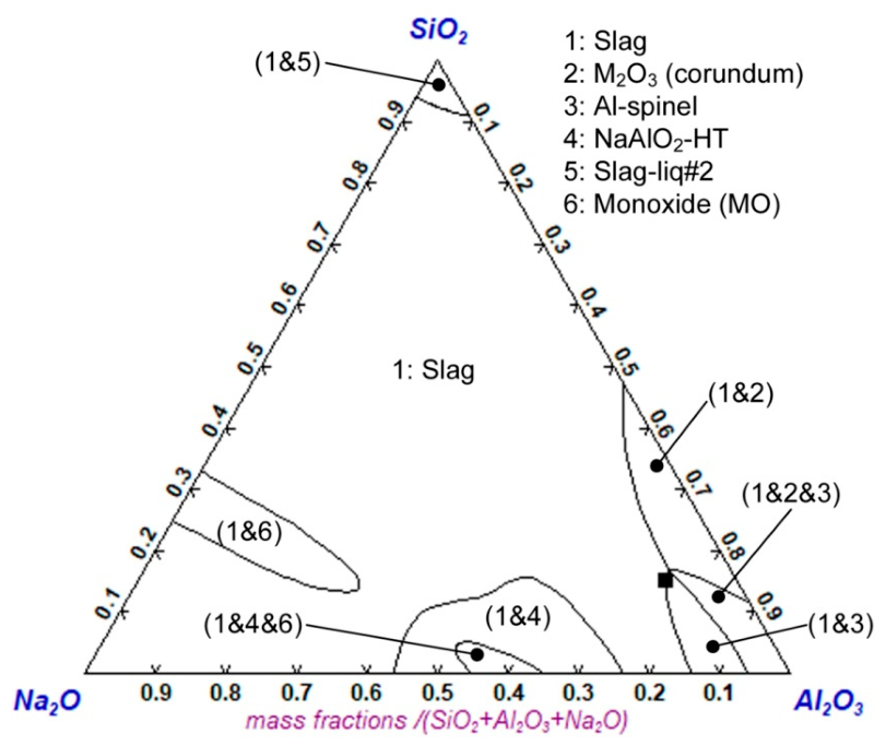
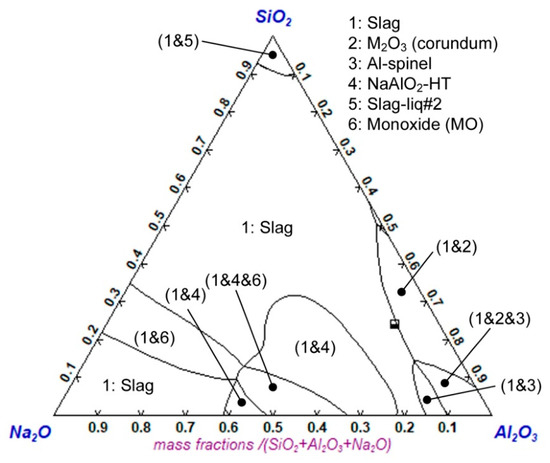
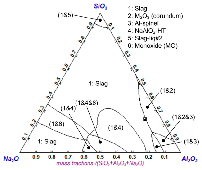
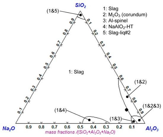
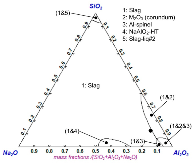
The target slag composition is 17% SiO2, 11% Na2O, 39% Al2O3, 17% CaO, and 14% MnO, at 80% manganese recovery to the alloy. The phase chemistry of this slag at 1450 °C is depicted in Figure 2. Due to the low alumina content in the ore and the minimal alumina added via the small coal addition, the feed mixture has low alumina content, below 5%. It is clear from Figure 2 that the selected slag can accommodate a large quantity of Al2O3 in the glass phase, even at moderate temperatures such as 1450 °C, and still remain fully liquid.
Figure 2.
Liquidus projection for target slag at 1450 °C (%CaO = 25; %MnO = 20); diamond = target composition.
In the following sections, the slag SEM-EDS results for slag samples A-D are compared to the equilibrium phase chemistry presented in the pseudo-ternary liquidus projection phase diagram for each slag at its slag liquidus temperature. The liquidus temperature of each slag composition was pre-calculated and then applied in the liquidus projection calculations. Due to variations in %CaO and %MnO among the slags, the projection of the composition point for each slag is shown individually.
3.2. Slag A
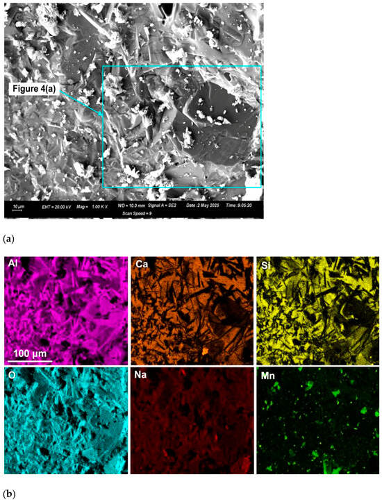
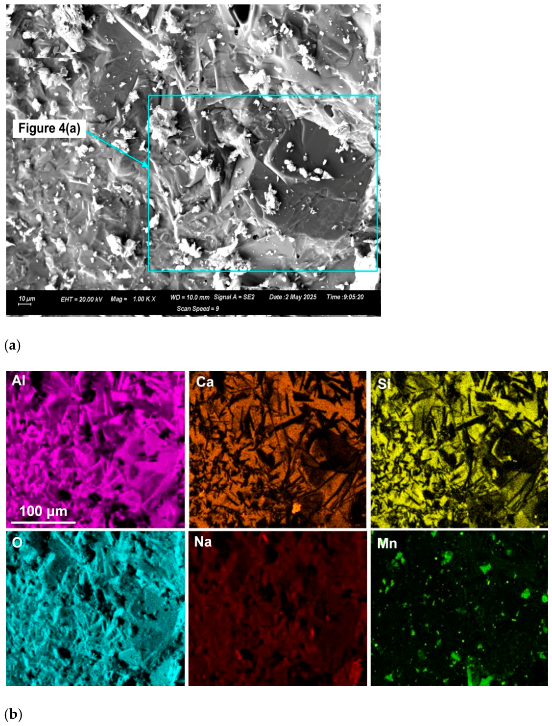
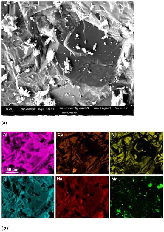
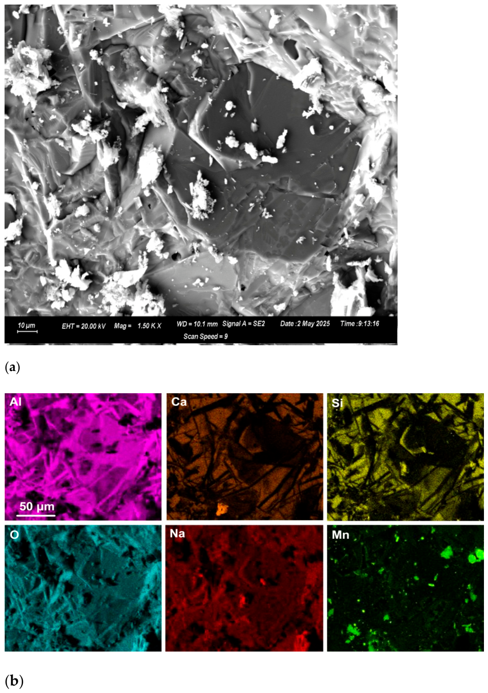
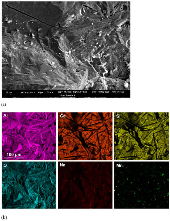
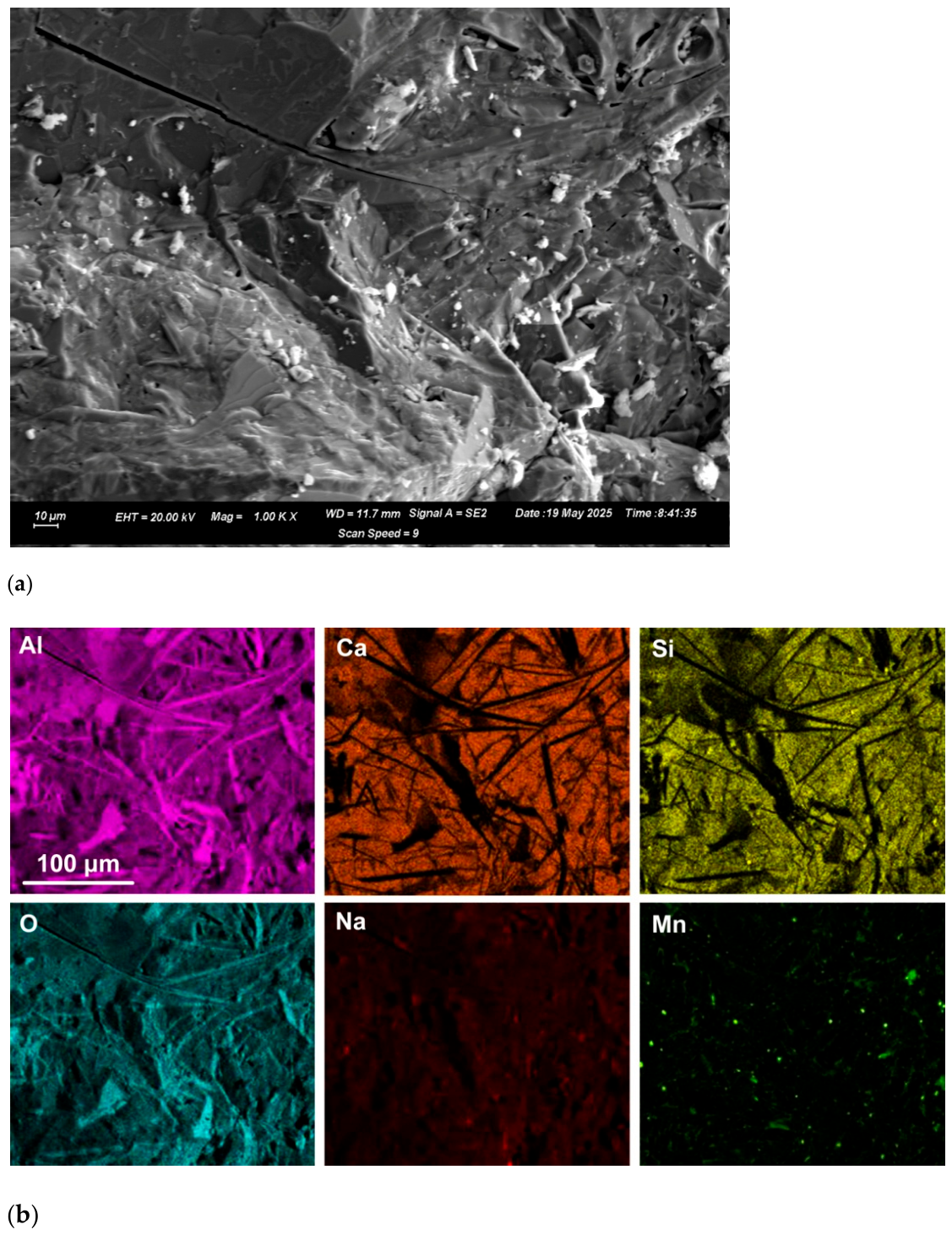
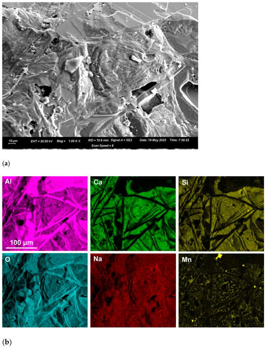
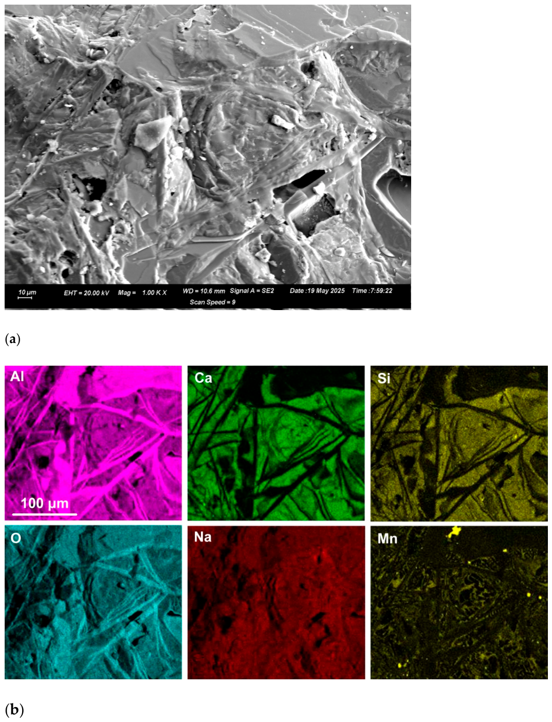
Table 3 and Figure 3 display the slag SEM-EDS results for sample A. The bulk slag chemistry is also shown in Table 3 as previously reported following correction for entrapped alloy [16]. It is observed that %MnO and %Al2O3 are higher than the targeted values, indicating inefficient Al reduction of MnO. All the iron oxide was reduced to metal, as no iron oxide was analysed in the slag phases. The EDS maps in Figure 3 and Figure 4 display distinct alumina-rich strands embedded within a glass matrix composed of SiO2, Na2O, Al2O3, CaO, and MnO. Surface particulates containing Mn and O indicate volatilisation and recondensation of some manganese. However, these particulates do not represent the MnO contained in the slag. The pseudo-ternary liquidus projection phase diagram for the average slag composition in Table 3 is shown in Figure 5, indicating a liquidus temperature of 1655 °C (marked as a triangle on the diagram). This point can be taken as confirmation that the reaction temperature in the mixture was at 1655 °C or higher. Although some Al2O3-rich phase areas can be seen in Figure 3 and Figure 4, the quantity of alumina in these phase areas does not change the average composition significantly, as shown in Table 3 for Area 5 analysis vs. the blocked Area 5 as indicated in Figure 3a and shown in Figure 4a,b at ×1500 magnification. The apparent high alumina phase area, which constitutes more than 50% of the field of view (FOV) in Figure 4, has a similar composition of 61% Al2O3 to that of the FOV in Figure 3, at 59% Al2O3. The alumina-rich phase areas in Figure 4 are not pure alumina. The alumina-rich strands contain some Na2O and MnO, but no Si and Ca. This composition trend also holds for the blocky, large alumina-rich area spanning 50% of the FOV in Figure 4. In comparison, the average composition point marked in Figure 5 indicates the primary solidification phase (PSP) as corundum (pure Al2O3). At the nearby (slag + M2O3 + spinel) phase boundary, the spinel composition is 91% MnAl2O4 and 9% Al2O3. The solid-phase compositions shown in Figure 3 deviate from the precise equilibrium compositions since there appears to be Na2O contained in the high Al2O3 solid-phase areas, whilst MnO contents are less clear.
Table 3.
Average EDS analysis of areas in Slag A (mass%).
Figure 3.
(a) SEM image (×1000) of Area 5 in Slag A. (b) EDS element map of Area 5 in Slag A.
Figure 5.
Slag A liquidus projection at 1655 °C (%CaO = 11; %MnO = 29); triangle = average composition.
3.3. Slag B
The phase features in the EDS maps of Figure 6 appear similar to those of Slag A in Figure 3 and Figure 4, with distinct alumina-rich strands embedded in the glass matrix. Slag B appears closer to the target slag composition, as displayed in Table 4. This may be expected since copper is not easily oxidised and is expected to increase the alloy volume, facilitating the coalescence of alloy droplets for efficient separation of slag and alloy. Slag B has a liquidus temperature of 1572 °C with Al-spinel as the PSP, as displayed in Figure 7. The Al-spinel equilibrium composition is 96% MnAl2O4 and 4% Al8O12.
Figure 6.
(a) SEM image (×1000) of Area 6 in Slag B. (b) EDS element map of Area 6 in Slag B.
Table 4.
Average EDS analysis of areas in Slag B (mass%).
Figure 7.
Slag B liquidus projection at 1572 °C (%CaO = 16; %MnO = 17); square = average composition.
3.4. Slag C
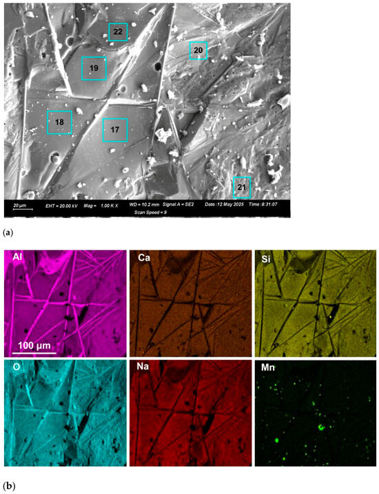
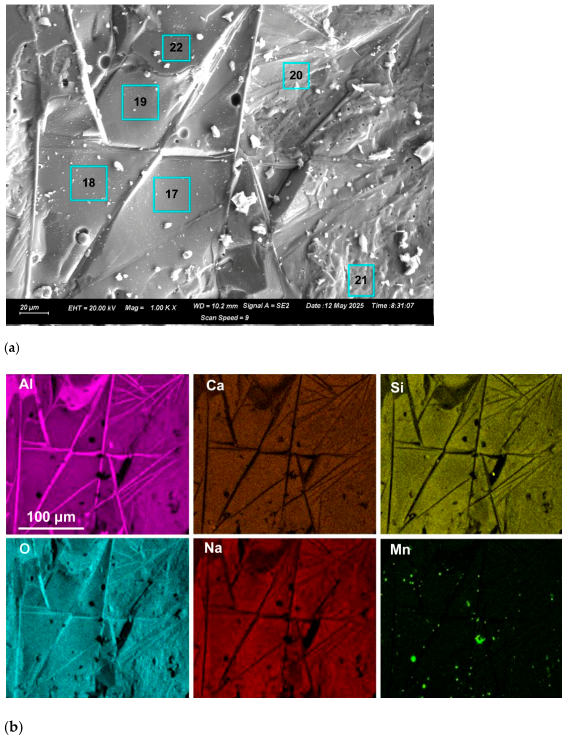
Since the Sample C feed mixture contains silicon metal, and Si can also serve as a reductant, SiO2 is formed and appears to be added to the slag, compared to the other slags. The B2 values are more acidic than expected, as shown in Table 5. To better gauge differences in phase composition, specific areas marked in Figure 8a were analysed. The analyses are shown in Table 6, with the liquidus temperature for each composition point (excluding the effect of BaO). It is observed that although the compositions of areas 17-21 do not differ significantly, the liquidus temperature shifts from 1465 °C to 1579 °C. The high alumina composition at 77% in area 22 has a liquidus temperature of 1921 °C. The EDS element maps in Figure 8b show a similar flow pattern for area 22 and the alumina-rich strands, which leads one to conclude that these strands were molten during formation in the aluminothermic reduction reactions at temperatures likely higher than 1921 °C. Figure 9 shows the pseudo-ternary diagram at the liquidus temperature of the average composition of Slag C, 1537 °C. Figure 9 shows the PSP as corundum (100% Al2O3). This is in agreement with the SEM-EDS observations, which show the alumina-rich strands in Figure 8b with no Na2O content, indicating pure Al2O3 strands. The melting point of pure alumina is 2053 °C, indicating that the reaction temperatures in sample C should have reached this temperature to melt the pure alumina strands. This effect is not seen in Slags A, B and D, in which the alumina-rich strands appear with Na2O contained. Although the area 22 analysis in Table 6 appears to be impure alumina, the EDS interaction volume below the surface may include some of the matrix phase, which could account for the alumina impurity.
Table 5.
Average EDS analysis of areas in Slag C (mass%).
Figure 8.
(a) SEM image (×1000) of Area 16 in Slag C. (b) EDS element map of Area 16 in Slag C.
Table 6.
Average EDS analysis of areas in Slag C, Area 16 (mass%).
Figure 9.
Slag C liquidus projection at 1537 °C (%CaO = 16; %MnO = 9); square = average composition.
3.5. Slag D
The EDS element maps in Figure 10b show larger high-alumina areas with rounded edges, similar to those in Figure 8b, indicating that these areas were molten at the reaction temperature. The alumina-rich strands in Figure 10b appear similar to those in Figure 8b, displaying fine strands that flow into the matrix phase, with some alumina-rich strands exhibiting diffuse endpoints. The curved pattern of alumina-rich strands in Figure 10b indicates flow patterns, confirming that the alumina-rich strands were molten at the reaction temperature. The average composition of Slag D from Table 7, has a liquidus temperature of 1647 °C, as shown in Figure 11. Slag D appears similar to Slag B in average composition, although chromium metal was added to the sample D feed mixture, and copper metal was added to the sample B mixture. The EDS analyses showed no general chromium uptake in the oxide phases, indicating that chromium remained in the metallic form. The alumina content in Slag D is higher at 59% compared to 55% in Slag B. Slag D has a significantly higher liquidus temperature than Slag B, due to its higher alumina content—1647 °C versus 1572 °C. The MnO levels are similar in both slags. However, this does not mean the same level of manganese alloy formation was attained in both samples.
Figure 10.
(a) SEM image (×1000) of Area 24 in Slag D. (b) EDS element map of Area 24 in Slag D.
Table 7.
Average EDS analysis of areas in Slag D (mass%).
Figure 11.
Liquidus projection for Slag D at 1647 °C (%CaO = 15; %MnO = 17); circle = average composition.
The comparative alloy performance from each feed mixture, based on mass-balance measurements, is shown in Table 8 [23]. It is seen that bulk alloy formation was highest in sample D at 30.6 g of alloy, followed by sample B at 28.6 g, then sample C at 19.2 g. Sample A cannot be compared on absolute mass basis since the 10 g of collector metal is absent in mixture A. Sample C, with added Si metal, performed worst in terms of alloy entrainment due to the viscous slag formed from increased network-forming SiO2 in the slag [16]. Sample B, with added copper collector metal performed best in terms of limiting alloy entrainment. The alloy yield percentage is highest in sample D, at 68%, most likely due to the oxygen partial pressure stabilisation effect of chromium [23]—unlike in the case of silicon collector metal, which participated in silicothermic reduction in MnO to add SiO2 to the slag, so increasing the slag viscosity and entrapping more alloy [15,16].
Table 8.
Alloy formation performance (units are grams, unless specified differently).
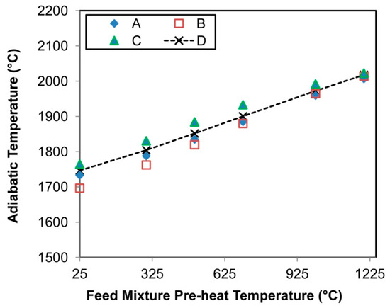
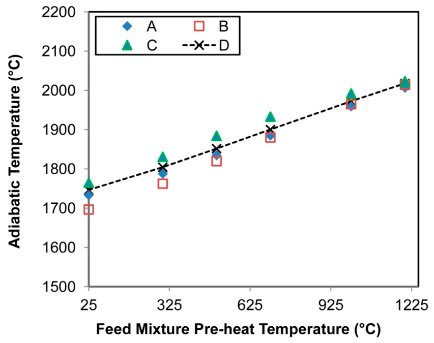
In addition to the above comparison of the slags’ phase chemistry to equilibrium slag thermochemistry, the likelihood of reaching reaction equilibrium should be investigated. It is well accepted that the SHS method does not lead to complete process equilibrium due to fast reaction rates and the formation of a reaction front, but that phase chemistries close to equilibrium are expected due to high reaction temperatures [10,11]. The calculation of a process temperature range is complicated by the fast reaction and the reaction front progression through the reacting mixture. The adiabatic temperature (AT) is usually calculated as the likely maximum temperature, yielding temperatures of 2000 °C to 3000 °C [10,23,24]. An experimentally determined guideline for SHS of refractory compounds (carbides, borides, nitrides, silicides) requires AT higher than 2227 °C [10]. The AT values for mixtures A to D are similar at 3290 °C to 3366 °C [23]. Figure 12 shows the adiabatic temperatures for the feed mixtures at different mixture pre-heating temperatures. It is seen that the AT values are similar, regardless of the feed mixture applied in this work. The effect of mixture pre-heating is large. The main uncertainty remains the temperature reached by the bulk products of slag and alloy and the best indicator from this work is the presence of molten pure alumina strands in mixture C, indicating that 2054 °C was reached within the slag mass.
Figure 12.
Adiabatic temperatures.
The results indicate that the target slag design must accommodate variability in alumina content, MnO content, and flux uptake (e.g., Na2O and CaO), while maintaining adequate fluidity in the aluminothermic process. The target slag and experimental slags’ solidus and liquidus temperatures are summarised in Table 9. The low solidus temperatures, despite the high alumina content, are crucial for providing adequate alloy–slag separation time. The phase chemistry and slag morphology appear similar in all four slags, as evidenced by the presence of molten alumina-rich strands within a Na2O-SiO2-Al2O3-MnO-CaO matrix phase. In Slags A, C, and D, the equilibrium calculations indicated that corundum was the primary solidification phase. Pure alumina strands were only seen in Slag C. The other slags (A, B, D) contained impure alumina strands containing some Na2O and MnO, but no Si and Ca. Therefore, the analysed phase chemistry does not precisely correspond to the equilibrium phase chemistry in the phase diagrams.
Table 9.
Slag liquidus and solidus temperatures (°C) and %alumina-rich strands in slags.
The percentage area of alumina-rich strands per slag was quantified using ImageJ software (version 1.54s) [22]. The average was taken from the area percentage measured for each SEM-EDS analysed area as listed in Table 3, Table 4, Table 5 and Table 7. The numbers in Table 9 are close to 1% to 2%, confirming the interpretation of the bulk chemistry of each slag being at the liquidus lines as shown in Figure 5, Figure 7, Figure 9 and Figure 11. The area percentage values are similar in volume percentage because of the high alumina content of the slag, resulting in slag density of 2.7-2.9 g/cm3. The volume percentage values were calculated from the bulk slag components’ molar volumes and the effective slag molar masses [25]. In comparison, the density of pure alumina at its melting point (2054 °C) is 3.01 g/cm3 [26].
Comparison of the phase field sizes in Figure 2, Figure 5, Figure 7, Figure 9 and Figure 11 shows that the (slag + NaAlO2) phase field expands with decreased %MnO in the slag. The maximum reduction in MnO from the feed mixture is essential in enhancing NaAlO2 formation. The NaAlO2 compound is targeted because it is highly soluble in water, but the dissolution of sodium-aluminosilicates in water was also reported [20]. Although the target slag was not attained as planned, the alloy yields are comparable to those reported in the literature [12]. The attained slags contain less Na2O and CaO than the target slag chemistry, likely due to the volatilisation of Na2O and the loss of CaO, since a finely powdered CaO input material was used. The loss of elements such as Na is due to Na2O volatilisation and can be limited by modulating the maximum process temperatures through feed sequencing and adding heat sink materials, for example, adding discard metal fines and Al2O3 to the feed mixture [10]. Volatiles should be captured by off-gas and dust collection systems, typically applied on industrial production facilities [2]. As highlighted previously, the slag composition can be adjusted after tapping from the aluminothermic reduction step, by adding Na2O to ensure NaAlO2 formation during slag solidification [16]. The water leachability of the slag when modified by different levels of Na2O additions, combined with differing slag cooling rates, should be investigated.
4. Conclusions
- A novel sodium-oxide fluxed slag is designed and applied in the aluminothermic reduction in MnO2-type ore. The slag’s high Al2O3 solubility facilitates the recycling of Al2O3 through hydrometallurgical processes, where NaAlO2 serves as a water-leachable compound.
- Thermochemical software is used to explain the slag phase chemistry in the Na2O-SiO2-Al2O3-MnO-CaO slag system. Slag liquidus temperatures of 1655 °C, 1572 °C, 1537 °C and 1647 °C were calculated. All the slags contained distinct alumina-rich strands embedded within a Na2O-SiO2-Al2O3-MnO-CaO glass matrix. The proportion of alumina-rich strands varies from 1.5% to 2.1%. The alumina-rich strands appear molten, indicating that the processing temperatures exceeded their liquidus temperatures, up to 1921 °C. Instances of pure alumina strands with a molten morphology indicate temperatures above 2053 °C, the melting point of Al2O3.
- Phase diagram calculations show expansion of the (slag + NaAlO2) phase field with decreased %MnO. Thus, maximum reduction in MnO from the feed mixture is essential in enhancing NaAlO2 formation.
- Even though the target slag composition was not attained, the slag composition can be adjusted after tapping from the aluminothermic reduction step, by adding Na2O to ensure NaAlO2 formation during slag solidification. Therefore, future work should include investigation of the modified slag’s water leachability, following different levels of Na2O addition and slag cooling rates.
Author Contributions
Conceptualization, F.D.B.; Methodology, T.C. and F.D.B.; Software, T.C.; Formal Analysis, T.C. and F.D.B.; Investigation, T.C. and F.D.B.; Data Curation, T.C.; Writing—Original Draft, T.C.; Writing—Review and Editing, T.C. and F.D.B. All authors have read and agreed to the published version of the manuscript.
Funding
This research was funded in part by the University of Pretoria.
Data Availability Statement
The original contributions presented in this study are included in the article. Further inquiries can be directed to the corresponding author.
Acknowledgments
Gratitude to Coenraad Snyman at the Laboratory for Microscopy and Microanalysis at the University of Pretoria for his advice and assistance on SEM work.
Conflicts of Interest
The authors declare no conflicts of interest. The funders had no role in the design of the study; in the collection, analyses, or interpretation of data; in the writing of the manuscript, or in the decision to publish the results.
Abbreviations
The following abbreviations are used in this manuscript:
| ASR | Aluminothermic smelting reduction |
| SHS | Self-propagating high-temperature synthesis |
| PSP | Primary solidification phase |
| PID | Proportional-integral-derivative |
| SEM | Scanning electron microscope |
| EDS | Energy dispersive spectroscopy |
| ICP-OES | Inductively coupled plasma optical emission spectroscopy |
| FOV | Field of view |
| SD | Standard Deviation |
References
- Habashi, F. (Ed.) Handbook of Extractive Metallurgy; Wiley-VCH: Weinheim, Germany, 1997; pp. 420–451. [Google Scholar]
- Gasik, M. Handbook of Ferroalloys; Butterworth-Heinemann: Oxford, England, 2013; pp. 495–499. [Google Scholar]
- Kumar, P.; Safarian, J. Sustainable production of ultra-low-carbon ferromanganese and calcium aluminate slag from pre-reduced manganese ore using aluminium. Can. Metall. Q. 2025, 1–22. [Google Scholar] [CrossRef] [Scilit]
- Kudyba, A.; Akhtar, S.; Johansen, I.; Safarian, J. Aluminothermic Reduction of Manganese Oxide from Selected MnO–Containing Slags. Materials 2021, 14, 356. [Google Scholar] [CrossRef] [Scilit] [PubMed]
- Kudyba, A.; Safarian, J. Manganese and Aluminium Recovery from Ferromanganese Slag and Al White Dross by a High Temperature Smelting–Reduction Process. Materials 2022, 15, 405. [Google Scholar] [CrossRef] [Scilit] [PubMed]
- Philipson, H.; Wallin, M.; Einarsrud, K.E.; Tranell, G. Kinetics of silicon production by aluminothermic reduction of silica using aluminum and aluminum dross as reductants. In Proceedings of the 16th International Ferro-Alloys Congress (INFACON XVI), Trondheim, Norway, 27–29 September 2021. [Google Scholar]
- Philipson, H.G.R.; Wallin, M.; Einarsrud, K.E. Aluminothermic Reduction Kinetics of Calcium Silicate Slag for Silicon Alloy Production. Metals 2024, 14, 604. [Google Scholar] [CrossRef] [Scilit]
- Tranell, G.; Safarian, J.; Wallin, M. SisAl—A New Process for Production of Silicon. In Silicon for the Chemical and Solar Industry XV; NTNU: Trondheim, Norway, 2020; pp. 129–139. ISBN 978-82-997357-9-7. [Google Scholar]
- Heo, J.H.; Park, J.H. Thermochemical analysis for the reduction behavior of FeO in EAF slag via Aluminothermic Smelting Reduction (ASR) process: Part 1. Effect of aluminum on Fe & Mn recovery. CALPHAD 2017, 58, 219–228. [Google Scholar] [CrossRef] [Scilit]
- Merzhanov, A.G. Problems of combustion in chemical technology and in metallurgy. Russ. Chem. Rev. 1976, 45, 409–420. [Google Scholar] [CrossRef] [Scilit]
- Mossino, P. Some aspects in self–propagating high–temperature synthesis. Ceram. Int. 2004, 30, 311–332. [Google Scholar] [CrossRef] [Scilit]
- Bhoi, B.; Murthy, B.V.R.; Datta, P.; Rajeev; Jouhari, A.K. Studies on Aluminothermic Reduction of Manganese ore for Ferro Manganese Making. Ferro Alloy Industries in the Liberalised Economy; Vatsh, A.K., Singh, S.D., Goswami, N.G., Ramachandrarao, P., Eds.; NML: Jainshedpur, India, 1997; pp. 66–70. [Google Scholar]
- Rafiei, M.; Ahmadnezhad, M.; Mostaan, H.; Saeidi, A. Reaction mechanism in SiO2–MnO2–Fe–Al system for producing ferrosiliconmanganese powder. Adv. Powder Technol. 2020, 31, 2613–2617. [Google Scholar] [CrossRef] [Scilit]
- Barsukova, N.V.; Popov, A.V.; Komarov, O.N. Evolution of structure and properties of iron–carbon alloys produced by aluminothermy at differentiation of fractional composition of charge materials. Metallurgist 2025, 68, 1743–1755. [Google Scholar] [CrossRef] [Scilit]
- Barsukova, N.V.; Komarov, O.N.; Zhilin, S.G.; Predein, V.V.; Popov, A.V.; Khudyakova, V.A. Control of Properties of Iron–Carbon Alloys Produced by Aluminothermy by Varying Technological Factors. Metallurgist 2023, 67, 1192–1207. [Google Scholar] [CrossRef] [Scilit]
- Coetsee, T.; De Bruin, F. Sodium Oxide–Fluxed Aluminothermic Reduction of Manganese Ore with Synergistic Effects of C and Si Reductants: SEM Study and Phase Stability Calculations. Reactions 2025, 6, 40. [Google Scholar] [CrossRef] [Scilit]
- Coetsee, T.; De Bruin, F. Sodium–Oxide Fluxed Aluminothermic Reduction of Manganese Ore for a Circular Economy: Cr Collector Metal Application. Sustain. Chem. 2025, 6, 30. [Google Scholar] [CrossRef] [Scilit]
- Coetsee, T.; De Bruin, F. Investigation of Copper as Collector Metal in Sodium-Oxide Fluxed Aluminothermic Reduction of Manganese Ore. Crystals 2026, 16, 50. [Google Scholar] [CrossRef] [Scilit]
- Azof, F.I.; Safarian, J. Leaching kinetics and mechanism of slag produced from smelting–reduction of bauxite for alumina recovery. Hydrometallurgy 2020, 195, 105388. [Google Scholar] [CrossRef] [Scilit]
- Pilla, G.; Hertel, T.; Pontikes, Y. Toward an integrated and sustainable Bauxite residue valorization, employing H2 reduction roasting, carbonation, and bio–carbon smelting. J. Sustain. Metall. 2025, 11, 1745–1765. [Google Scholar] [CrossRef] [Scilit]
- Bale, C.W.; Bélisle, E.; Chartrand, P.; Decterov, S.A.; Eriksson, G.; Gheribi, A.E.; Hack, K.; Jung, I.-H.; Kang, Y.-B.; Melançon, J.; et al. FactSage thermochemical software and databases, 2010–2016. Calphad 2016, 54, 35–53, Reprinted in Calphad 2016, 55, 1–19.. [Google Scholar] [CrossRef] [Scilit]
- Schneider, C.A.; Rasband, W.S.; Eliceiri, K.W. NIH Image to ImageJ: 25 years of image analysis. Nat. Methods 2012, 9, 671–675. [Google Scholar] [CrossRef] [Scilit] [PubMed]
- Coetsee, T.; De Bruin, F. Thermodynamic Assessment of Reactions in the Sodium-Oxide Fluxed Aluminothermic Reduction of Manganese Ore with Si, Cr, and Cu Collector Metals. Crystals 2026, 16, 120. [Google Scholar] [CrossRef] [Scilit]
- Sparis, D.; Lazou, A.; Balomenos, E.; Panias, D. Thermodynamics of Aluminothermic Processes for Ferrotitanium Alloy Production from Bauxite Residue and Ilmenite. Metals 2024, 14, 200. [Google Scholar] [CrossRef] [Scilit]
- Verein Deutscher Eisenhüttenleute (VDEh). Slag Atlas, 2nd ed.; Verlag Stahleisen GmbH: Düsseldorf, Germany, 1995; pp. 345–346. [Google Scholar]
- Turkdogan, E.T. Physicochemical Properties of Molten Slags and Glasses; The Metals Society: London, UK, 1983; p. 2. [Google Scholar]

Disclaimer/Publisher’s Note: The statements, opinions and data contained in all publications are solely those of the individual author(s) and contributor(s) and not of MDPI and/or the editor(s). MDPI and/or the editor(s) disclaim responsibility for any injury to people or property resulting from any ideas, methods, instructions or products referred to in the content. |
© 2026 by the authors. Licensee MDPI, Basel, Switzerland. This article is an open access article distributed under the terms and conditions of the Creative Commons Attribution (CC BY) license.