


Abstract
Air-floating transport provides a noncontact solution for handling large flexible sheets in precision manufacturing. However, variations in the spatial distribution of air-film support during transport can induce localized deformation, particularly when the sheet crosses gaps between adjacent support regions. This study investigates the deformation characteristics of thin flexible sheets during air-floating transport using a coupled model of the sheet and supporting air film. The evolution of sheet deformation is analyzed at representative transport positions. A relative displacement measure is introduced to quantify local edge sagging. The effects of guide gap, air supply conditions represented by the equivalent parameter Q, initial installation gap, and negative pressure are systematically examined. The results show that deformation is particularly pronounced near the sheet edges during transitions between support regions. Among the investigated parameters, guide gap has the strongest influence on edge sagging, while the effects of the equivalent supply parameter Q and negative pressure are relatively limited within the examined ranges. These findings provide guidance for configuring air-floating transport systems to reduce undesirable sheet deformation.
1. Introduction
Ultra-thin, large-area sheets are widely used in precision manufacturing fields such as display manufacturing, flexible electronics, semiconductor processing, and thin-film devices [1,2,3]. Owing to their low bending stiffness and high surface quality requirements, these sheets are highly susceptible to contact-induced damage, contamination, and out-of-plane deformation during handling and transport [4]. Air-floating systems, which support the sheets on a thin air film, provide an effective contactless handling solution that avoids mechanical contact and minimizes damage risk [5,6].
From a mechanical perspective, the deformation and dynamic behavior of flexible sheets in air-floating systems are governed by the coupled interaction between the air film and the deformable sheet. This air–sheet coupling directly affects flying height stability and transport reliability, particularly in precision manufacturing processes involving large-area flexible sheets. Accordingly, existing studies related to this problem can be broadly classified into three categories. The first group of studies employs coupled numerical and analytical models to investigate fluid–structure interaction (FSI). For example, FSI models based on the finite element method (FEM) have been developed for aerostatic thrust bearings [7], while finite difference discretization combined with Newton–Raphson iteration has been employed to investigate the static and dynamic characteristics of hybrid gas foil bearings [8]. Two-way transient FSI has also been applied to aerostatic guideway systems with cantilever-type sliders [9], and fully coupled models have been used to analyze pressure, deformation, and wear in high-speed airfoil thrust bearings [10]. Related studies have also developed analytical FSI models to investigate the vibration and stability of axially moving plates immersed in fluid [11]. These high-fidelity models can capture the detailed coupling between air-film pressure and structural deformation. However, when extended to the time-varying deformation prediction of large-area sheets under transport conditions, high-fidelity numerical approaches can incur substantial computational costs, making them less suitable for rapid computation [12,13].
The second group of studies focuses on simplified or efficient computational methods developed to reduce the computational cost of coupled and structural dynamic analyses. To improve the computational efficiency of modeling the interaction between the air film and the structure, enhanced transfer matrix methods [14], perturbation-based approaches for dynamic coefficient calculation [15], real-time coupled bearing–rotor dynamic models [16], and Galerkin-based reduced-order methods have been investigated [17]. Galerkin and semi-analytical methods have also been used for nonlinear and efficient dynamic analysis of plate structures [18,19]. These studies demonstrate that reduced-order and semi-analytical formulations can substantially improve the computational efficiency of structural dynamic simulations [20,21]. However, such methods are usually formulated for specific structural configurations, boundary conditions, or operating assumptions. Their applicability in predicting the position-dependent deformation of flexible sheets moving across discontinuous air-film supports requires further investigation.
The third group of studies is more closely related to air-floating support and transport in engineering applications. Representative studies have investigated the design of air-floating devices for display substrate transport [22], the influence of nozzle spacing on substrate deformation in orifice-restricted air-floating systems [23], and deformation control strategies based on air-film pressure feedback [24]. These studies provide valuable guidance for the design and control of practical air-floating systems. Coupled models have been developed to predict the responses of gas-bearing systems [25,26], while related studies have examined the effects of bearing configurations and operating conditions on air-film pressure distributions and coupled system responses [27,28]. In our previous work, a coupled dynamic model based on modal superposition was developed to predict the deformation response of large flexible sheets under air-film support [29]. However, during continuous transport across separated air-bearing regions, the spatial distribution of the supporting air film varies with the sheet position, leading to changes in the local support conditions. Such variations may induce localized sagging near the leading and trailing edges, while different regions of the sheet exhibit distinct deformation histories. Nevertheless, the spatially nonuniform deformation of flexible sheets under single-edge vacuum clamping during transport across discontinuous support regions comprising multiple porous air-bearing modules remains insufficiently characterized.
In this study, the deformation behavior of thin flexible sheets during transport across discontinuous air-film supports is investigated using a coupled model of the flexible sheet and supporting air film. Building upon the coupled modeling framework established in our previous work [29], the present study further considers changing sheet-module overlap under single-edge clamping and systematically investigates local edge sagging and parameter effects, distinguishing its focus from the gap-crossing analysis in Ref. [22]. Representative tracking points are introduced to characterize the deformation histories at different sheet locations, and a relative displacement measure is used to quantify local edge sagging. The effects of the guide gap, equivalent supply parameter Q, initial installation gap, and negative pressure are then examined. The results provide insights into the deformation characteristics of flexible sheets during transitions between air-bearing regions and offer guidance for the configuration and operation of air-floating transport systems.
2. Methodology and Model
2.1. Coupled Model of the Flexible Sheet and Air Film
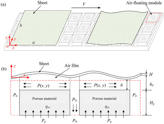
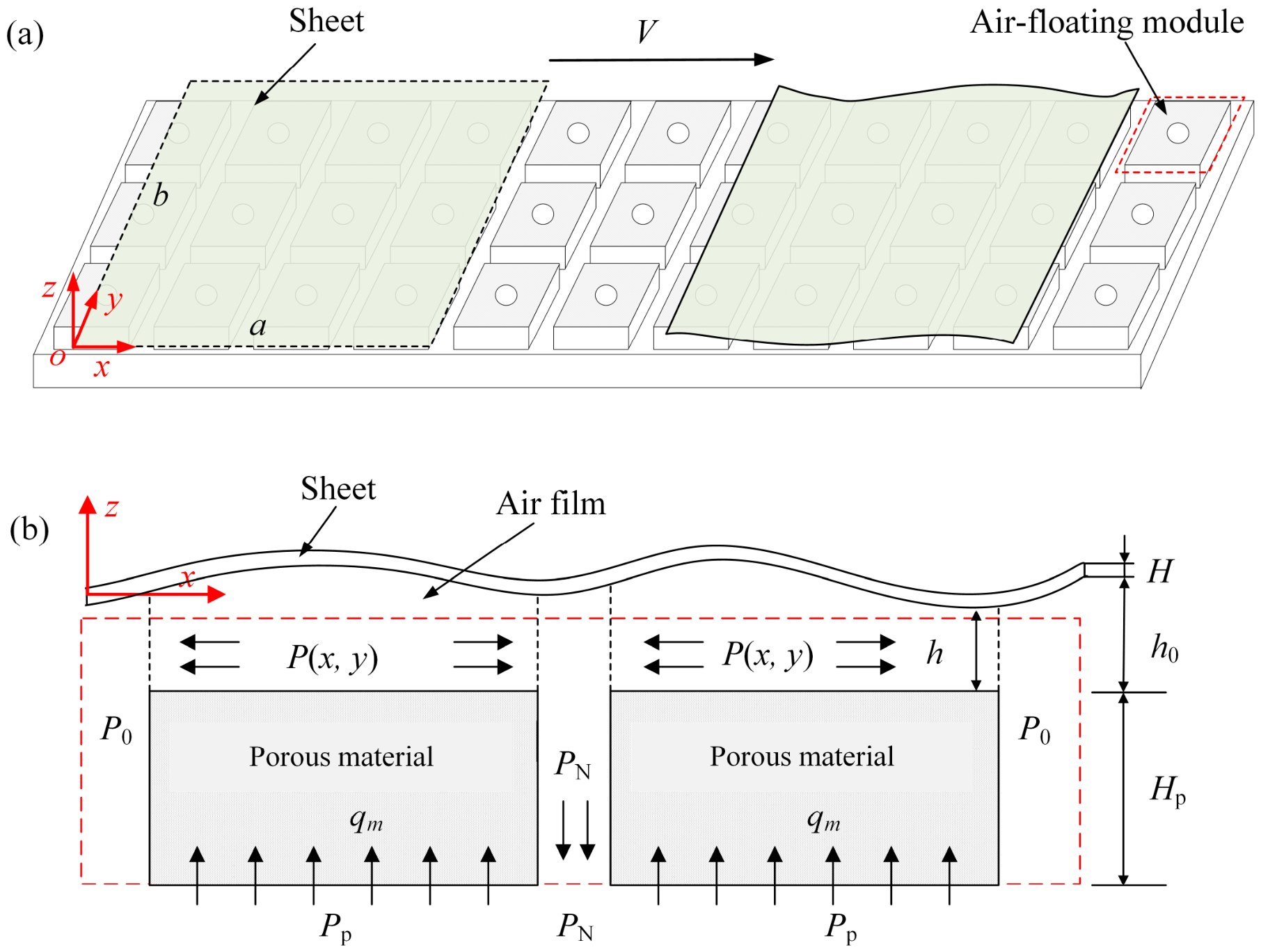
Figure 1a shows a flexible sheet supported by multiple air-floating modules arranged in arrays, which together form a high-precision air-floating platform for transporting large-area flexible sheets in industrial applications. Each module injects airflow to create a micron-scale air film beneath the sheet, generating a distributed pneumatic support force that maintains or regulates the flying height. To achieve accurate motion, one or both edges of the sheet are held by vacuum adsorption fixtures mounted on motorized stages, enabling controlled transport over the air-bearing surface. The remaining three edges are not mechanically constrained, so the sheet is modeled as a cantilever plate. The sheet is defined by length a, width b, thickness H, density ρs, Young’s modulus E, and Poisson’s ratio μ. As shown in Figure 1b, airflow enters the gap beneath the sheet through the throttling effect of a porous material of thickness Hp. Each module also includes a suction hole that generates negative pressure to fine-tune the flying height h and enhance sheet stability. h(x, y, t) denotes the instantaneous local gap height, which varies with position and time, while h0 denotes the prescribed initial installation gap between the module surface and the undeformed sheet. The out-of-plane deformation is defined as w = h − h0. The supply pressure at the porous material inlet is Pp, and the negative pressure is PN. The air-film pressure is P. The pressures Pp, PN, and P are expressed as gauge pressures, whereas P0 denotes the ambient absolute pressure.
Figure 1.
Schematic of the air-floating transport system: (a) Overall system configuration. (b) Local cross-sectional model and pressure boundary conditions of an air-floating module.
To model the dynamic behavior of the flexible sheet in the air-floating system, a Cartesian coordinate system (O, x, y, z) is established. The x- and y-axes define the mid-plane of the sheet, and the z-axis denotes the out-of-plane direction. The origin O is set at one corner point of the sheet. The transverse displacement of the sheet’s mid-plane along the z-direction is represented by w(x, y, t). The sheet is transported along the x-direction at a constant velocity V, driven by motorized stages. Based on the Kirchhoff thin plate assumption and the von Kármán strain–displacement relation [30], a reduced transverse model is adopted to describe the bending-dominated deformation of the sheet without explicitly solving the in-plane displacement field. The governing equation accounting for geometric nonlinearity can be written as follows:
D = EH3/[12(1 − μ2)] is the flexural rigidity of the sheet. w,x and w,y represent the first-order partial derivatives of w with respect to x and y. w,tt denotes the second-order derivative of w with respect to t, while w,xx, w,yy, and w,xy denote the second-order spatial derivatives.
To model the FSI in the air-floating system, the effect of the air film on the flexible sheet’s dynamics is analyzed under the following assumptions [29,31]:
- (1)
- The airflow through the porous material obeys Darcy’s law, governing flow behavior within the air-floating modules.
- (2)
- The narrow gap between the porous material and the flexible sheet supports the application of the Reynolds equation to describe the gap flow.
- (3)
- The suction hole maintains a constant negative pressure PN, while the edges of the porous material are exposed to ambient pressure.
- (4)
- The transport velocity of the flexible sheet is much lower than the airflow velocity, so the Couette flow contribution in the Reynolds equation is neglected.
- (5)
- The air-film pressure adjusts much faster than the sheet response. Therefore, the density variation and transient pressure storage term in the thin air film are neglected.
Based on these assumptions and mass conservation, the air-film pressure within an individual air-floating module is governed by the following simplified Reynolds equation, where the spatial gradients of the air film thickness are neglected under the assumption of small local gap variations:
where η is the air viscosity, and u0 represents the airflow velocity through the porous material. Based on Darcy’s law for one-dimensional isothermal compressible flow, u0 can be expressed as
where kp is the permeability coefficient of the porous material.
Because the thin flexible sheet has a low areal weight, the required gauge air-film pressure is relatively low under the considered operating conditions, satisfying P << Pp and P << P0. Substituting Equation (3) into Equation (2) yields the modified Reynolds equation:
In this air-floating system, Br denotes the suction hole region, where a negative pressure PN is applied, and Bc represents the boundary exposed to the ambient pressure P0. The grooves between adjacent air-floating modules and the gap between Areas I and II are treated as regions without effective air-film support, where the gauge pressure is set to zero. Equations (4) and (5) form a Poisson-type equation with Dirichlet boundary conditions, governing the pressure distribution of the air film. The air-film pressure distribution generated by an air-floating module with an arbitrary shape can then be expressed as
The functions f1(x, y) and f2(x, y) depend solely on the geometry of the air-floating module and the sheet-module overlap and are determined for prescribed overlap states by solving the following equations:
∇2 f1(x,y) = −1
∇2 f2(x,y) = 0
During transport, the spatial pressure functions are solved over the actual sheet-module overlap region, including cases where the suction region is partially covered, while uncovered regions provide no effective air-film support. Considering the deformation of the flexible sheet, an approximate solution for P can be obtained through a Taylor series expansion:
For simplification, the following dimensionless coordinates and parameters are introduced:
Substituting Equations (11) and (13) into Equation (1) yields the following dimensionless equation:
The dimensionless transverse displacement is approximated by the following modal expansion:
where I = MN, and the single index i corresponds to the modal pair (m, n).
The cantilever sheet is clamped along the y = 0 edge and free along the other edges. φ() and ψ() are the basic functions in the x- and y-directions. A convenient choice is
with
The dimensionless boundary conditions are
2.2. Computational Model and Operating Conditions
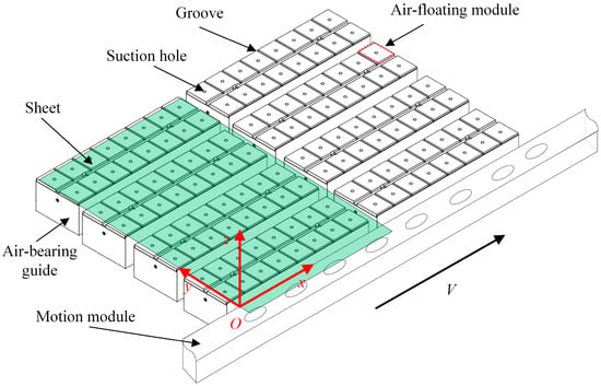
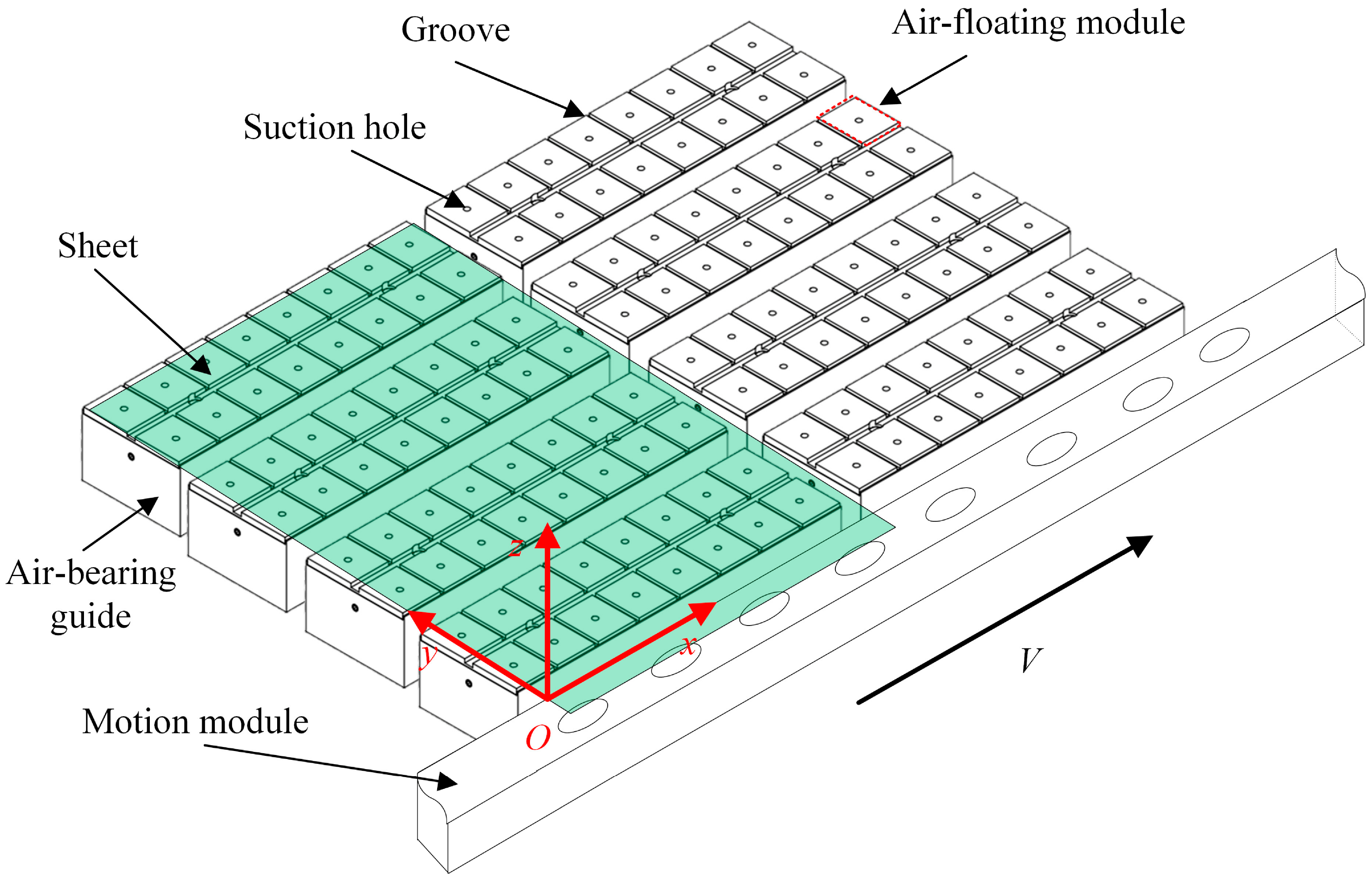
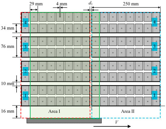
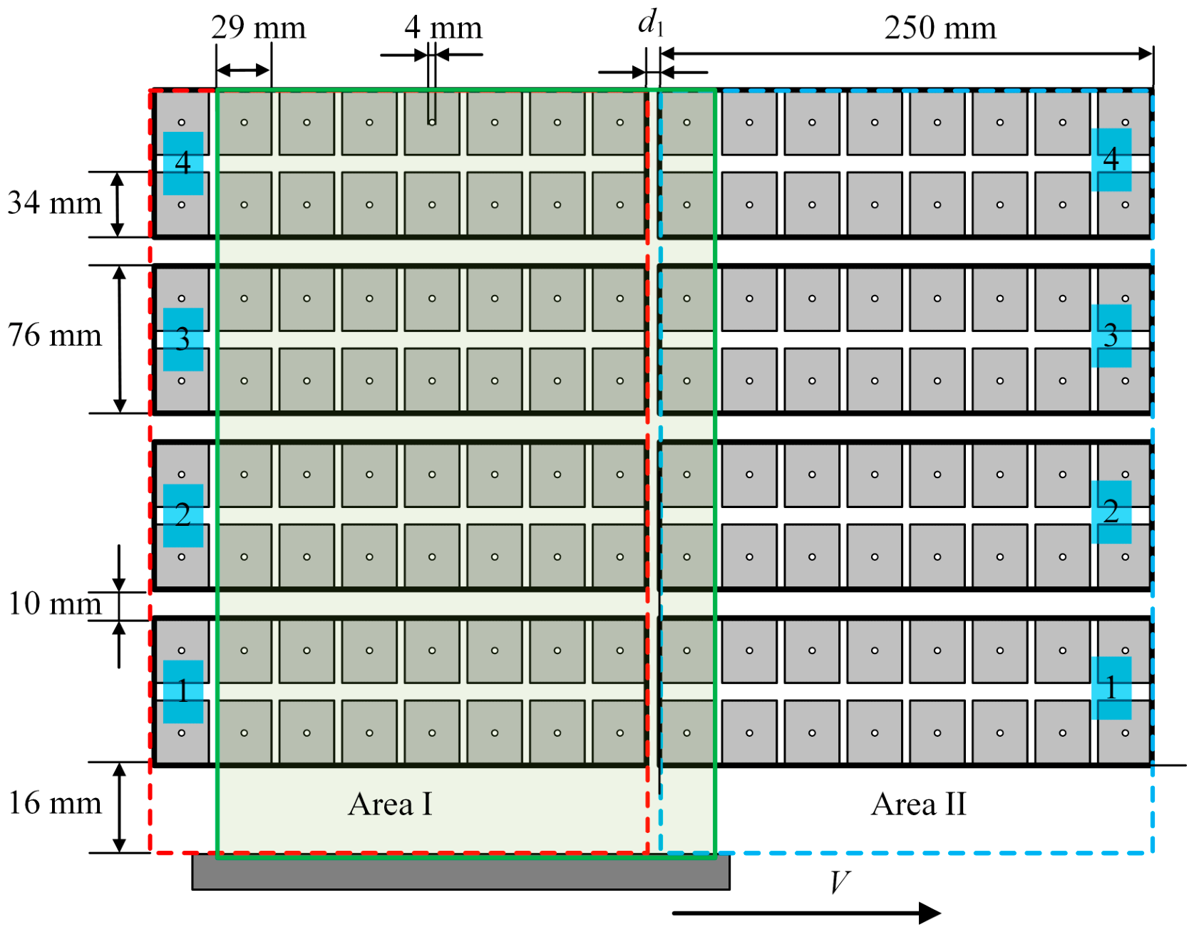
The air-floating platform consisted of independent air-bearing guides, each equipped with a dedicated pneumatic circuit. The initial installation gap h0 between the fixed edge of the sheet and each guide was measured on the platform. The structural configuration and geometric layout of the platform are shown in Figure 2. The air-floating transport system combines vacuum edge clamping with distributed air-film support to enable the controlled transport of flexible sheets. As illustrated in Figure 2, the sheet was transported along the guide direction by the motion module, while the distributed air-floating modules provided noncontact support beneath the sheet. As the sheet moves along the platform, its relative position with respect to the stationary air-floating modules changes continuously, resulting in position-dependent support conditions. Each guide consisted of 16 air-floating modules separated by grooves, which isolated adjacent modules and reduced interference between neighboring flow fields.
Figure 2.
Structural schematic of the air-floating platform.
The platform was divided into Area I and Area II, each containing four guides. Each module measured 34 mm × 29 mm and incorporated a suction hole with a diameter of 4 mm. Adjacent guides were separated by a spacing of 10 mm, forming discontinuous support regions across the sheet width. In addition, a 16 mm gap was reserved from the fixed edge of the sheet, and a gap d1 = 16 mm separated Areas I and II. As the sheet moved from Area I to Area II, the gap between the two areas caused a temporary reduction in the local air-film support, which could lead to localized sheet deformation. The geometric partition shown in Figure 3 was also adopted in the numerical model to define the spatial distribution of the air-film support and the relative position between the sheet and the platform during transport.
Figure 3.
Platform layout and dimensional parameters of the air-floating platform.
For the numerical simulations, the theoretical model with uniform h0, Q, and PN was extended to a guide-dependent form, with h0 measured and Q and PN identified for each guide. The identified parameters are summarized in Table 1. The first subscript denotes the area, and the second subscript denotes the guide number within that area.
Table 1.
Parameters for air-bearing guides.
A glass sheet used in the air-floating transport system was selected as the study object, and its geometric and material parameters are listed in Table 2. The sheet has a length of 250 mm, a width of 350 mm, and a thickness of 0.55 mm. In the numerical calculations, M = 5 and N = 5 beam functions were retained in the x- and y-directions, respectively, resulting in a total of 25 modes. The absolute ambient pressure and dynamic viscosity of air were set to P0 = 101,325 Pa and η = 1.81 × 10⁻⁵ Pa·s, respectively. At each prescribed transport position S, the quasistatic equilibrium is determined using the Galerkin method by setting the time derivatives in Equation (14) to zero.
Table 2.
Material and geometric parameters of the sheet.
3. Results and Discussion
3.1. Deformation Evolution During Transport
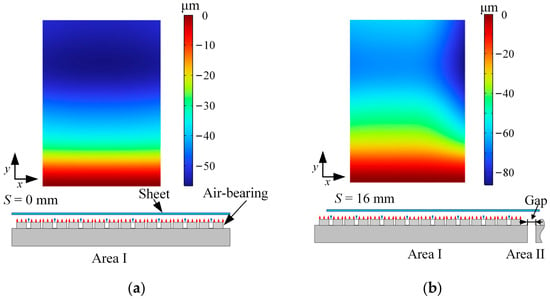
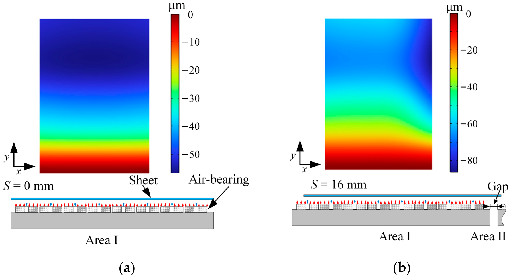
Figure 4 shows the deformation evolution of the sheet at representative transport positions during air-floating transport, where S denotes the transport distance of the sheet. At the initial position, the sheet is supported by the air-bearing guides in Area I, and a nonuniform deformation distribution is observed due to guide-dependent variations in pneumatic and installation parameters, as shown in Figure 4a. The downward deformation generally increases from the constrained edge toward the free edge, reflecting the influence of the boundary constraint on the deformation distribution. When the sheet moves into the gap between Area I and Area II, part of the sheet loses air-film support, resulting in increased sagging, particularly near the unsupported leading edge, as shown in Figure 4b. These results indicate that the deformation distribution is influenced by both the boundary constraints and the spatial variation in the supporting air film during transport.
Figure 4.
Evolution of sheet deformation at representative positions during air-floating transport: (a) S = 0 mm. (b) S = 16 mm.
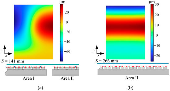
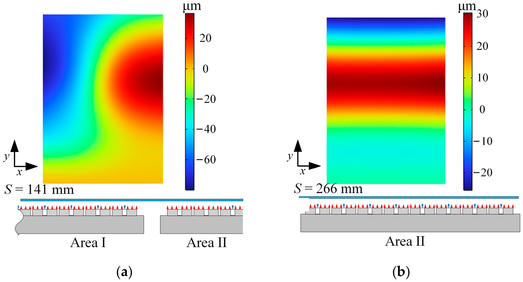
As the sheet continues to move forward, it spans both Area I and Area II, with portions of the sheet supported by the air-bearing guides on both sides. Accordingly, the deformation field evolves as the support configuration changes, as shown in Figure 5a. At this position, the sheet exhibits a highly nonuniform deformation distribution, with positive and negative out-of-plane displacements occurring in different regions. This indicates that the change in support configuration affects not only the deformation magnitude but also its spatial distribution. At the end position, the sheet is fully supported by the guides in Area II and returns to a fully supported state, as shown in Figure 5b. Compared with the intermediate position, the deformation exhibits a more regular distribution, with larger displacements concentrated in the central region of the sheet. It should be noted that the air-film stiffness increases significantly as the flying height decreases, making contact with the air-bearing surfaces less likely. In contrast, the absence of air-film support across the gap between adjacent support areas leads to more pronounced local sagging and a greater potential risk of contact near the support edges.
Figure 5.
Evolution of sheet deformation at representative positions during air-floating transport: (a) S = 141 mm. (b) S = 266 mm.
3.2. Local Edge Sagging Characteristics
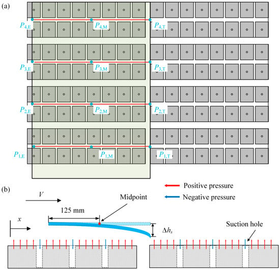
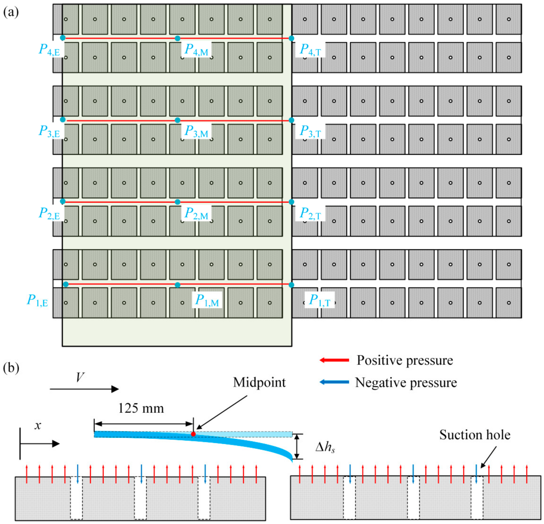
As shown in Figure 6a, twelve representative tracking points were selected to examine the deformation evolution of the flexible sheet. These twelve tracking points are arranged in four rows along the centerlines of the air-bearing guides at y = 54, 140, 226, 312 mm, with each row containing a leading edge (Pi,T), mid-span (Pi,M), and trailing-edge (Pi,E) point, allowing characterization of deformation both along the transport direction and across the sheet width. As illustrated in Figure 6b, when the sheet crosses the inter-area gap between Area I and Area II, the leading edge temporarily sags under gravity due to reduced local air-film support, while the mid-span region remains relatively supported. To quantify this edge sagging, the sagging height is defined as the relative out-of-plane displacement between the leading-edge and mid-span points in each row:
where w(Pi,T) and w(Pi,M) are the out-of-plane displacements of the leading-edge and mid-span points in the i-th row, with Pi,M located at x = 125 mm, so that Δhs,i quantifies the magnitude of local edge sagging across the inter-area gap. The sagging height is evaluated at S = d1.
Figure 6.
Tracking point arrangement and definition of edge sagging: (a) Locations of the twelve tracking points. (b) Definition of the sagging height Δhs as the sheet crosses the inter-area gap.
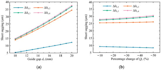
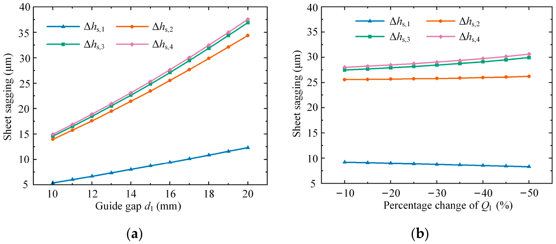
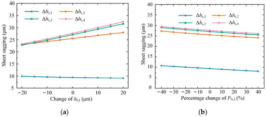
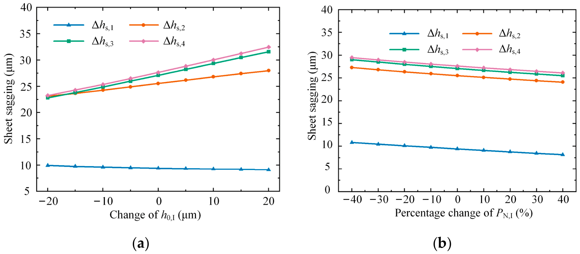
Figure 7 and Figure 8 show the effects of the guide gap d1, equivalent parameter QI, initial installation gap h0,I, and negative pressure PN,I on the sagging height Δhs. The reference values of QI, h0,I, and PN,I are given in Table 1, with a reference guide gap of d1 = 16 mm. The investigated ranges are 10–20 mm for d1, −10% to −50% for QI, −20 to 20 μm for h0,I, and −40% to 40% for PN,I, with the latter three expressed relative to their respective reference values. These ranges represent variations in support spacing, installation conditions, and air-supply operating conditions. For all cases, the sagging height near the fixed edge Δhs,1 remains much smaller than those near the free side (Δhs,2, Δhs,3, and Δhs,4), indicating that weakly constrained regions are more prone to edge sagging. As shown in Figure 7a, increasing d1 enlarges the unsupported region between adjacent air-bearing guides and weakens the local air-film support, leading to a rapid increase in Δhs. When d1 increases from 10 mm to 20 mm, the sagging heights in the three rows away from the fixed edge increase from approximately 15 μm to 34–38 μm, whereas Δhs,1 increases more moderately. This difference indicates that the influence of the guide gap becomes more pronounced in regions farther from the constrained boundary. Figure 7b shows that reducing QI slightly increases Δhs in the three rows away from the fixed edge, because insufficient positive pressure supply reduces the load-carrying capacity and stiffness of the air film. However, the corresponding changes in sagging height are relatively small, generally within a few micrometers over the investigated range, while Δhs,1 exhibits a slight decrease. Compared with the effect of guide gap, variations in QI have a more limited influence on edge sagging under the considered conditions. The reference values are listed in Table 1, and the investigated parameter ranges were selected based on practical experience in the design and operation of air-floating transport systems.
Figure 7.
Effects of key parameters on the sagging height Δhs: (a) Guide gap d1. (b) Variation in QI (decreasing from −10% to −50% from left to right).
Figure 8.
Effects of key parameters on the sagging height Δhs: (a) Variation in h0,I. (b) Variation in PN,I (−40%, 0%, and +40% correspond to −30, −50, and −70 Pa, respectively).
The sagging height exhibits a moderate sensitivity to h0,I, particularly near the free side, as shown in Figure 8a. As h0,I increases from −20 μm to 20 μm relative to its reference value, the sagging heights near the free side increase from approximately 23 μm to 28–33 μm, while Δhs,1 decreases slightly. This indicates that the influence of the initial installation gap is more pronounced in regions farther from the constrained boundary. A smaller h0,I slightly suppresses sagging near the free side by increasing air film stiffness, but it also reduces the safety clearance. Figure 8b shows that PN,I has a limited influence on Δhs within the examined range. As the percentage change of PN,I increases from −40% to 40%, the sagging heights decrease gradually at all four positions, with a reduction of approximately 3–4 μm in the regions away from the fixed edge. This indicates that negative pressure can regulate local edge sagging, although its effect is less pronounced than that of the guide gap. Within the investigated ranges, the changes in sagging height away from the fixed edge are approximately 19–23 μm for d1, 5–10 μm for h0,I, and only a few micrometers for QI and PN,I. Overall, d1 is the dominant factor affecting edge sagging, followed by h0,I, whereas QI and PN,I exert comparatively weaker influences within the examined parameter ranges.
4. Conclusions
This study investigated the deformation characteristics of thin flexible sheets during air-floating transport across discontinuous support regions using a coupled sheet and air film model. The main conclusions are summarized as follows:
- (1)
- The results indicate that variations in the spatial distribution of air-film support lead to nonuniform deformation during transport. Local edge sagging becomes particularly pronounced when the leading edge crosses the gap between adjacent support regions.
- (2)
- A relative displacement measure was introduced to characterize local edge sagging. Parametric results show that the spacing between adjacent air-bearing regions has the strongest influence on edge sagging within the investigated parameter ranges. The initial installation gap also affects the deformation response, whereas variations in air supply conditions represented by the equivalent parameter Q and negative pressure produce comparatively smaller changes.
- (3)
- These findings suggest that maintaining support continuity and controlling installation conditions are important for limiting undesirable deformation during air-floating transport. Further evaluation of minimum flying height is needed to establish practical operating limits that account for both deformation and contact clearance.
Author Contributions
D.K.: Writing—Original Draft, Conceptualization, Software, Methodology, Investigation, Formal Analysis, Data Curation. Y.F.: Validation, Data Curation. J.C.: Writing—Review & Editing, Supervision, Project Administration. All authors have read and agreed to the published version of the manuscript.
Funding
This work was supported by the CUI CAN Program of Guangdong Province (Grant No. CC/XM-202402ZJ0102) and the Advanced Materials—National Science and Technology Major Project (Grant 2025ZD0615500).
Institutional Review Board Statement
Not applicable.
Informed Consent Statement
Not applicable.
Data Availability Statement
The original contributions presented in this study are included in the article. Further inquiries can be directed to the corresponding author.
Conflicts of Interest
Author Yu Fu was employed by the company Wuhan National Innovation Technology Optoelectronics Equipment Co., Ltd. The remaining authors declare that the research was conducted in the absence of any commercial or financial relationships that could be construed as a potential conflict of interest.
Nomenclature
| a | Sheet length (m) |
| b | Sheet width (m) |
| H | Sheet thickness (m) |
| ρs | Sheet density (kg/m3) |
| E | Young’s modulus (Pa) |
| μ | Poisson’s ratio |
| D | Flexural rigidity (N·m) |
| h0 | Initial installation gap (m) |
| Hp | Porous material thickness (m) |
| w | Out-of-plane sheet deflection (m) |
| h | Local flying height (air film thickness) (m) |
| Pp | Supply pressure (Pa) |
| Q | Equivalent parameter (Pa·m) |
| PN | Negative pressure applied to the suction region (Pa) |
| P0 | Constant ambient pressure (Pa) |
| P | Air-film pressure distribution (Pa) |
| V | Sheet transport velocity (m/s) |
| η | Dynamic viscosity of air (Pa·s) |
| u0 | Darcy velocity through porous material (m/s) |
| kp | Permeability of the porous material (m2) |
| Dimensionless sheet deformation | |
| Dimensionless in-plane coordinates | |
| Dimensionless time | |
| ξ | Sheet aspect ratio, ξ = a/b |
| c1 | Auxiliary coefficient in the dimensionless governing equation, c1 = EH3/[12a2b2(1 − μ2)] |
| h0,I,j, h0,II,j | Initial installation gaps of the j-th guide in Areas I and II (m) |
| PN,I,j, PN,II,j | Negative pressures applied to the suction regions of the j-th guide in Areas I and II (Pa) |
| QI,j, QII,j | Equivalent flow parameter of the j-th guide in Areas I and II (Pa·m) |
| f1(x, y), f2(x, y) | Spatial pressure functions |
| φm | m-th free-free beam function in the x-direction |
| ψn | n-th clamped-free beam function in the y-direction |
| γm | m-th characteristic root of the free-free beam function |
| βn | n-th characteristic root of the clamped-free beam function |
| ϕi | i-th retained mode shape |
| τm | Coefficient of the m-th free-free beam function |
| σn | Coefficient of the n-th clamped-free beam function |
| qi, qmn | Modal coordinate in single- and double-index forms |
| M | Number of retained beam functions in the x-direction |
| N | Number of retained beam functions in the y-direction |
| I | Total number of retained modes, I = MN |
| (·),r, (·),rr | First- and second-order derivatives with respect to r = x, y, t |
| Δhs,i | Local edge sagging displacement in the i-th guide row (m) |
References
- Yue, X.; Chen, J.; Yang, H.; Li, X.; Xiong, J.; Yin, Z. Multinozzle Droplet Volume Distribution Control in Inkjet Printing Based on Multiagent Soft Actor–Critic Network. IEEE/ASME Trans. Mechatron. 2025, 30, 447–457. [Google Scholar] [CrossRef] [Scilit]
- Wang, Y.; Chen, J.; Yue, X.; Tang, W.; Yin, Z. A high-flexible multi-objective stochastic planning system based on nozzle-combined printing in display manufacturing. J. Manuf. Syst. 2024, 76, 627–643. [Google Scholar] [CrossRef] [Scilit]
- Xiong, J.; Chen, J.; Chen, W.; Yue, X.; Zhao, Z.; Yin, Z. Intelligent path planning algorithm system for printed display manufacturing using graph convolutional neural network and reinforcement learning. J. Manuf. Syst. 2025, 79, 73–85. [Google Scholar] [CrossRef] [Scilit]
- Breńkacz, Ł.; Witanowski, Ł.; Drosińska-Komor, M.; Szewczuk-Krypa, N. Research and applications of active bearings: A state-of-the-art review. Mech. Syst. Signal Process. 2021, 151, 107423. [Google Scholar] [CrossRef] [Scilit]
- Luo, X.; Han, B.; Chen, X.; Li, X.; Jiang, W. Multi-physics modeling of tunable aerostatic bearing with air gap shape compensation. Tribol. Int. 2021, 153, 106587. [Google Scholar] [CrossRef] [Scilit]
- Amano, K.; Yoshimoto, S.; Miyatake, M.; Hirayama, T. Basic investigation of noncontact transportation system for large TFT-LCD glass sheet used in CCD inspection section. Precis. Eng. 2011, 35, 58–64. [Google Scholar] [CrossRef] [Scilit]
- Gao, Q.; Qi, L.; Gao, S.; Lu, L.; Song, L.; Zhang, F. A FEM based modeling method for analyzing the static performance of aerostatic thrust bearings considering the fluid-structure interaction. Tribol. Int. 2021, 156, 106849. [Google Scholar] [CrossRef] [Scilit]
- Xu, F.; Dong, Z.; Zhang, H.; Xie, Z. Vibration characteristics control of hybrid radial gas foil bearing-rotor system: Simulation and experiment. Mech. Syst. Signal Process. 2023, 198, 110402. [Google Scholar] [CrossRef] [Scilit]
- Qi, L.; Liu, L.; Gao, Q.; Yao, Y.; Lu, L.; Gao, S. Investigation on the influence of structural rigidity on the stiffness of aerostatic guideway considering fluid-structure interaction. Tribol. Int. 2022, 173, 107658. [Google Scholar] [CrossRef] [Scilit]
- Eickhoff, M.; Theile, A.; Mayer, M.; Schweizer, B. Analysis of Air Foil Thrust Bearings with annular top foil including wear prediction, Part I: Modeling and simulation. Tribol. Int. 2023, 181, 108174. [Google Scholar] [CrossRef] [Scilit]
- Yang, T.; Zhou, K.; Li, Y.; Gong, D.; Zhou, J.; Wen, L. Dynamic modelling and vibration behavior of axially moving honeycomb sandwich plates immersed in fluid. Thin-Walled Struct. 2026, 218, 113967. [Google Scholar] [CrossRef] [Scilit]
- Qiu, S.; Ke, C.; Li, K.; Zhang, X.; Peng, N.; Liu, L. Nonlinear dynamic analysis of a novel tangentially supplied aerostatic bearing-rotor system: Theory and experiment. Mech. Syst. Signal Process. 2025, 224, 112221. [Google Scholar] [CrossRef] [Scilit]
- Zhang, J.; Han, D.; Song, M.; Xie, Z.; Rao, Z.; Zou, D. Theoretical and experimental investigation on the effect of supply pressure on the nonlinear behaviors of the aerostatic bearing-rotor system. Mech. Syst. Signal Process. 2021, 158, 107775. [Google Scholar] [CrossRef] [Scilit]
- Chen, P.; Ding, J.; Zhuang, H.; Chang, Y. A novel method for studying fluid-solid interaction problems of the rotor system in air bearings with manufacturing errors. Mech. Syst. Signal Process. 2023, 202, 110709. [Google Scholar] [CrossRef] [Scilit]
- Liu, Y.; Sun, X.; Sepahvand, K.K.; Marburg, S. Theoretical analysis on the static and dynamic performances of a squeeze film air journal bearing with three separate pads structure. Int. J. Mech. Sci. 2021, 200, 106442. [Google Scholar] [CrossRef] [Scilit]
- Ma, S.; Yin, Y.; Chao, B.; Yan, K.; Fang, B.; Hong, J. A real-time coupling model of bearing-rotor system based on semi-flexible body element. Int. J. Mech. Sci. 2023, 245, 108098. [Google Scholar] [CrossRef] [Scilit]
- Pourashraf, T.; Bonello, P. A new Galerkin Reduction approach for the analysis of a fully coupled foil air bearing rotor system with bilinear foil model. J. Sound Vib. 2023, 546, 117367. [Google Scholar] [CrossRef] [Scilit]
- Wang, C.-G.; Song, X.-Y.; Zhang, Y.-W.; Han, Q.-K.; Chen, L.-Q. Semi-analytical modeling and vibration analysis of thin-walled plate structures with arbitrary geometric profiles. Thin-Walled Struct. 2026, 221, 114420. [Google Scholar] [CrossRef] [Scilit]
- Hoang, V.N.V.; Thanh, P.T. Influences of arbitrary-distributed Kerr foundation on free vibration and nonlinear transient response of functionally graded plate in thermal environment. Thin-Walled Struct. 2023, 188, 110802. [Google Scholar] [CrossRef] [Scilit]
- Shi, J.; Cao, H.; Jin, X. Dynamics of 5-DOF aerostatic spindle with time-varying coefficients of air bearing. Mech. Syst. Signal Process. 2022, 172, 109005. [Google Scholar] [CrossRef] [Scilit]
- Sepehry, N.; Manesh, M.M.M.; Amindavar, H.; Zhu, W.; Nejad, F.B. A POD-based reduced-order framework for nonlinear structural health monitoring of thin-walled beams and plates. Thin-Walled Struct. 2026, 226, 114874. [Google Scholar] [CrossRef] [Scilit]
- Miyatake, M.; Akahori, H.; Yoshimoto, S. Deformation of large liquid crystal display glass sheets across a gap between noncontact transportation devices. Precis. Eng. 2016, 46, 360–368. [Google Scholar] [CrossRef] [Scilit]
- Huang, B.; Fu, T.; Xu, X.; Chen, M.; Zhou, Y.; Zhang, Y.; Liu, S. A theoretical design method for the nozzle pitch of air-flotation system to reduce large liquid crystal display glass substrate’s deformation. Sci. Rep. 2020, 10, 19909. [Google Scholar] [CrossRef] [Scilit] [PubMed]
- Yang, R.; Zhong, W.; Lin, Y.; Li, C.; Fang, J. Estimation of deformation for a glass sheet on a noncontact air conveyor with film pressure feedback. Meas. Sci. Technol. 2020, 31, 035301. [Google Scholar] [CrossRef] [Scilit]
- Baum, C.; Hetzler, H.; Schröders, S.; Leister, T.; Seemann, W. A computationally efficient nonlinear foil air bearing model for fully coupled, transient rotor dynamic investigations. Tribol. Int. 2021, 153, 106434. [Google Scholar] [CrossRef] [Scilit]
- Lyu, P.; Cao, Y.; Li, W.; Feng, K. Modeling and characteristic investigation of practical gas dynamic bearings with stacked perforated foils. Tribol. Int. 2023, 188, 108888. [Google Scholar] [CrossRef] [Scilit]
- Chen, G.; Ge, Y.; Lu, Q.; Zhang, W.; Wang, S. Air film pressure field characteristics of aerostatic thrust bearing with orifice blockage. Int. J. Adv. Manuf. Technol. 2023, 124, 4317–4328. [Google Scholar] [CrossRef] [Scilit]
- Mahner, M.; Bauer, M.; Schweizer, B. Numerical analyzes and experimental investigations on the fully-coupled thermo-elasto-gasdynamic behavior of air foil journal bearings. Mech. Syst. Signal Process. 2021, 149, 107221. [Google Scholar] [CrossRef] [Scilit]
- Kong, D.; Fu, Y.; Xie, M.; Tang, W.; Bai, K.; Chen, J.; Yin, Z. Dynamic response prediction of air-floating large-size sheet with mode superposition. Mech. Syst. Signal Process. 2025, 240, 113402. [Google Scholar] [CrossRef] [Scilit]
- Hakim, G.; Abramovich, H. Large Deflections of Thin-Walled Plates under Transverse Loading—Investigation of the Generated In-Plane Stresses. Materials 2022, 15, 1577. [Google Scholar] [CrossRef] [Scilit] [PubMed]
- Oiwa, N.; Masuda, M.; Hirayama, T.; Matsuoka, T.; Yabe, H. Deformation and flying height orbit of glass sheets on aerostatic porous bearing guides. Tribol. Int. 2012, 48, 2–7. [Google Scholar] [CrossRef] [Scilit]

Disclaimer/Publisher’s Note: The statements, opinions and data contained in all publications are solely those of the individual author(s) and contributor(s) and not of MDPI and/or the editor(s). MDPI and/or the editor(s) disclaim responsibility for any injury to people or property resulting from any ideas, methods, instructions or products referred to in the content. |
© 2026 by the authors. Licensee MDPI, Basel, Switzerland. This article is an open access article distributed under the terms and conditions of the Creative Commons Attribution (CC BY) license.