


Highlights
What are the main findings?
- CR-InSAR enables high-precision monitoring of vegetated highway slopes, achieving an RMSE of <0.3 mm against in situ sensors and capturing annual deformation rates of 0.1–0.4 mm/y.
- InSAR-constrained finite element strength reduction method shows that the current strength reduction factors are 0.11 and 0.12, which are far lower than the critical strength reduction factors of 1.28 and 1.22 for complete failure, which indicates that the cast-in-place and prefabricated frame beams demonstrated comparable support effectiveness.
What are the implications of the main findings?
- The integrated CR-InSAR and finite element framework provides a replicable method for quantitative stability assessment of vegetated slopes, overcoming the limitations of traditional inspections and InSAR in low-coherence areas.
- Field-validated equivalence of prefabricated and cast-in-place frame beams offers strong support for promoting low-carbon, efficient prefabricated technologies in mountainous highway construction.
Abstract
Highway slopes susceptible to landslides are typically reinforced by vegetation cover and the application of concrete frame beams, but vegetation cover may degrade the accuracy of InSAR deformation monitoring. We installed artificial corner reflectors (CRs) on the frame beams and assessed the stability of the vegetated slope using finite element simulation constrained by InSAR deformation data. A study was conducted on a typical landslide-risk slope within the K87 + 391.5–K87 + 565 section of the Guihuang highway, which is reinforced with cast-in-place and prefabricated concrete beams. Experimental results demonstrate that two adjacent corner reflectors (CRs) on the two types of frame beams of the slope can be successfully identified, with deformation rates ranging from 0.1 to 0.4 mm/y, and the root mean square error (RMSE) of discrepancies between CR-InSAR measurements and slope displacement monitoring sensors is less than 0.3 mm. Meanwhile, the current strength reduction factor values for slopes reinforced with cast-in-place and prefabricated concrete beams, as constrained by InSAR multi-dimensional deformation, are 0.11 and 0.12, respectively which are much lower than the critical strength reduction factors of 1.28 and 1.22 corresponding to full coalescence of plastic strain from the slope toe to the slope crest, which indicates that the cast-in-place and prefabricated frame beams exhibit comparable support performance.
1. Introduction
The topography of Guizhou province is dominated by plateaus and mountains, and highway slopes are prone to landslide disasters after heavy rainfall. Currently, the safety monitoring of highway slopes is predominantly conducted through manual inspections, with a limited quantity of monitoring sensors deployed on critical slopes, but these approaches are inadequate to comprehensively detect the latent hazards in slope safety. The interferometric synthetic aperture radar (InSAR), a technique capable of providing large-area and high-resolution deformation monitoring, offers a valuable approach to identifying landslide-risk slopes along highways [1,2].
InSAR-based landslide monitoring primarily utilizes the D-InSAR technique for displacement measurement pre- and post-landslides [3]. Utilizing the extensive application of SAR data, numerous researchers have proposed various multi-temporal InSAR techniques for landslide monitoring, such as PS-InSAR and SBAS-InSAR [4,5]. However, the penetration of short-wavelength SAR signals poses a limitation for InSAR landslide monitoring in regions with dense vegetation and complex topography. Strozzi et al. [6] applied L-band SAR interferometry data from JERS satellites to measure landslide displacement by penetrating vegetation. Nikolaeva et al. [7] employed L-band ALOS data to monitor the central Georgia landslide and to estimate the displacement field and volume of the landslide. The introduction of ALOS-2, LuTan-1, and other satellites has led to an increase in the availability of long-wavelength SAR data for landslide studies [8,9]. However, the spatial resolution and accuracy of long-wavelength InSAR for measuring deformation in vegetation are still insufficient for monitoring the deformation of highway slopes.
The deployment of artificial corner reflectors (CRs) has been demonstrated to generate stable echo signals in low-coherence vegetation areas [10], thereby improving the accuracy of InSAR deformation phase measurement. For InSAR landslide deformation monitoring, the CRs can serve as reference points for precise geographical positioning and as coherent targets for deformation monitoring. Quin and Loreaux [11] have verified that the deformation monitoring accuracy of the CRs can reach the sub-millimeter level, and many researchers used TerraSAR-X and Sentinel-1 data to analyze the effect of installing dihedral and trihedral reflectors on the Landslides, which can significantly improve the intensity and signal-to-clutter ratio, phase variance and positioning precision [12]. The CRs can also be applied in the sub-pixel offset time-series technique using SAR amplitudes [13]. Moreover, the integration of CR-InSAR and GPS displacement data for landslide monitoring can improve the accuracy of deformation along the slope to approximately 1~2 mm [14].
The strength reduction method based on finite element analysis is a prevalent approach for slope stability assessment [15]. This method incorporates the soil stress–strain relationship and facilitates the investigation of slope failure evolution processes [16,17,18]. A key challenge in applying the strength reduction FEM to slope stability assessment lies in determining slope failure from finite element calculation results. As demonstrated by Zheng and Zhao [19], the non-convergence of forces and displacements during finite element analysis indicates slope instability. This is based on the findings of Griffiths and Lane [16]. The generalized plastic strain or equivalent plastic strain along the slope from toe to crest is employed as an indicator of slope failure [20]. Advancements in computational technology have enabled numerous researchers to yield significant outcomes using the finite element strength reduction method. For instance, Yang et al. [21] employed finite element software to compute equivalent plastic deformation during slope instability, with a classic slope as a case study. Similarly, Wang and Tong [22] used the dynamic strength reduction method to identify the sliding surface of a slope, thereby enhancing the resolution of slope stability issues. Liu et al. [23] and Chiu et al. [24] integrated finite element analysis with rainfall data and seismic data, to offer critical insights into mountain slope stability and enhance the applicability of finite element analysis in slope stability assessment. Therefore, a framework that integrates CR-InSAR with finite element analysis enables the accurate assessment of vegetation-covered slope stability.
2. Methodology
2.1. Highway Risk Area Identification Based on Time-Series InSAR
The SBAS-InSAR technology utilizes coherence analysis and time series analysis to extract surface deformation information from multiple SAR images. Assuming that within a specified time interval, N + 1 Sentinel-1A satellite image acquisitions are collected, interferometric image pairs are then generated following the small baseline principle. From these N + 1 SAR images, a total of T interferograms are produced:
Within the periods of t1 and t2, n interferograms are generated. The azimuth coordinate of n is represented by x, and the range coordinate is represented by r. Then, the interferometric phase expression can be obtained through the formula:
where is the central wavelength of the radar, and and are the accumulated deformation amounts in the radar line of sight at a certain moment; while is the residual terrain phase, is the atmospheric delay phase, and is the noise error phase. And through the method of spatio-temporal filtering, the influences of and can be weakened. The final joint solution of multi-baseline small baseline subsets is derived using Singular Value Decomposition (SVD), and the least squares solution is acquired. Subsequently, the average deformation rate of the selected characteristic points over each time interval can be determined.
2.2. Vegetation-Covered Slope Monitoring Using CR-InSAR
The radar receiver mainly receives the echo signals emitted by the radar transmitter and returned by the ground interaction, which contain both amplitude information reflecting the strength of the electromagnetic wave and phase information related to the radar slant distance [25]. The information in each pixel consists of two components, the amplitude value and the phase value, and a complex number can represent these two components.
where i is the imaginary unit; a and b denote the real and imaginary parts of a complex number, respectively; is the amplitude representing the echo amplitude information, and is the phase.
To intuitively demonstrate the variations in radar echo intensity before and after the installation of corner reflectors, the linear values of radar echo intensity were converted into decibel values, as shown in Equation (4).
Acting as an artificial permanent scatterer, the differential interferometric deformation measurement equation of CR is formulated as follows:
where p denotes the number of CR points and m denotes the interferometric pair; represents the interferometric phase difference in the pth CR point; represents the integer ambiguity difference; represents the topography phase; is the deformation velocity of the CR point; represents the time baseline; relate to the flat Earth and orbital error phases; is the phase caused by the atmospheric delay; and is the residual phase and noise.
2.3. Finite Element Analysis Constrained by InSAR Multi-Dimensional Deformation
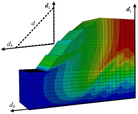
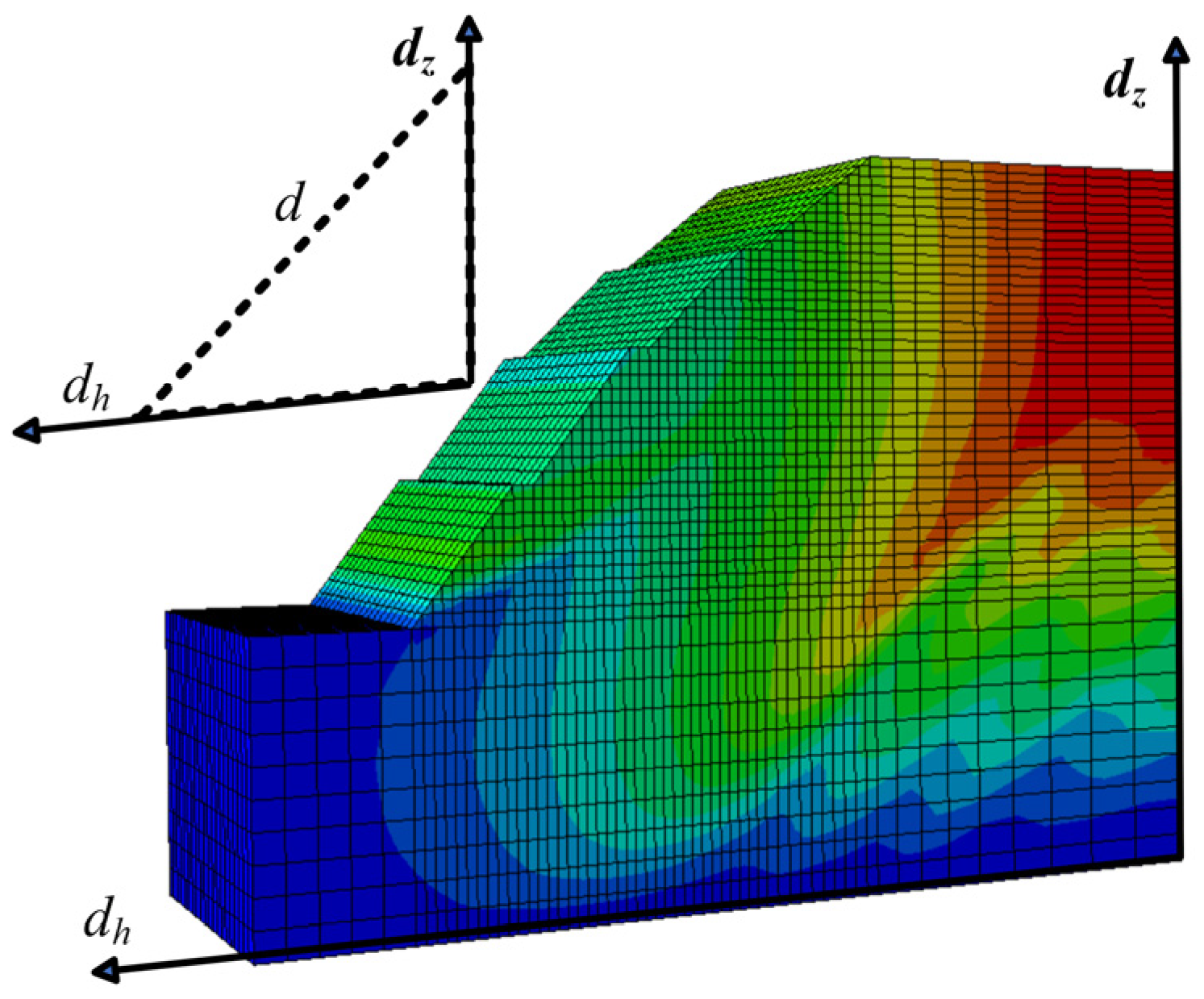
The slide-risk slopes will be subject to the force of gravity, which causes them to move in the direction of the largest topographic difference [26]. The finite element analysis model of the slope shows that the horizontal displacement along the slope is negligible. Therefore, the deformation along the slope can be decomposed into two components: the vertical component and the horizontal component perpendicular to the slope (see Figure 1), which can be directly imported into the finite element model for stability analysis.
Figure 1.
The InSAR deformation in the LOS direction is decomposed into vertical and horizontal components.
While the InSAR technique acquires the deformation in the LOS direction , it can be converted to and constrained by slope aspect:
where is the SAR incidence angle and is the angle between the heading and the horizontal direction perpendicular to the slope.
The essence of the strength reduction finite element method is to gradually reduce the shear strength parameters of slope rock and soil mass in ideal elastoplastic finite element calculation until the slope reaches a plastic failure state. Trial calculations are performed in finite element software with the strength reduction factor , and the calculation process is repeated by continuously adjusting until the slope is determined to reach the plastic failure state, and the corresponding value is defined as the critical strength reduction factor.
The strength reduction in the slope is defined as the shear strength indexes on the slip surface of the soil slope are reduced in the same proportion, and the reduced parameters are ; and . Where c is the cohesive force and φ is the angle of internal friction. Plastic penetration is selected as the criterion for slope instability in this study. In this method, the strength reduction factor is solved by iteratively increasing the reduction proportion until plastic penetration (complete failure) occurs in the slope; the corresponding to the critical instability state is defined as the critical strength reduction factor.
In finite element analysis, the overall deformation of the slope increases in conjunction with the increase in the reduction factor until the slope becomes unstable. The displacement parameter of the slope is not uniformly distributed; rather, it is a function of the node coordinates. If we assume that the slope model has a total of n nodes, then the total displacement mode D of the slope can be defined as follows [27]:
where is the horizontal displacement of the node, is the vertical displacement of the node, and n is the total number of slope nodes, which can be calculated by InSAR deformation model formula (6) and (7).
According to the cusp catastrophe theory [28], the relationship between the cusp catastrophe of the total displacement mode D and the strength reduction factor of the slope can be modeled by a fourth-degree polynomial:
where represents the coefficients. The horizontal and vertical displacements obtained by CR-InSAR are inserted to calculate the slope reduction factor at this instant. Then, the stability of the slope can be assessed by comparing the safety factor. The total displacement modulus D adopts the unweighted accumulation form of global nodes, which can objectively reflect the global evolution law of the overall slope deformation, avoid the artificial subjectivity of weighted indicators, and is a reasonable scalar parameter for characterizing the overall instability behavior of slopes in the cusp catastrophe theory. This fourth-order polynomial is the canonical mathematical form of cusp catastrophe theory. It is sufficiently flexible to capture the strong nonlinearity and abrupt transition characteristics of slope displacement with the strength reduction factor, which cannot be fully represented by simple linear or low-order polynomial functions. It is used to describe the nonlinear variation in the total slope displacement with the strength reduction factor, and can objectively identify the catastrophe point where the slope transitions from a stable state to a critical instability state.
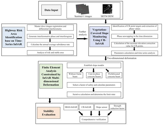
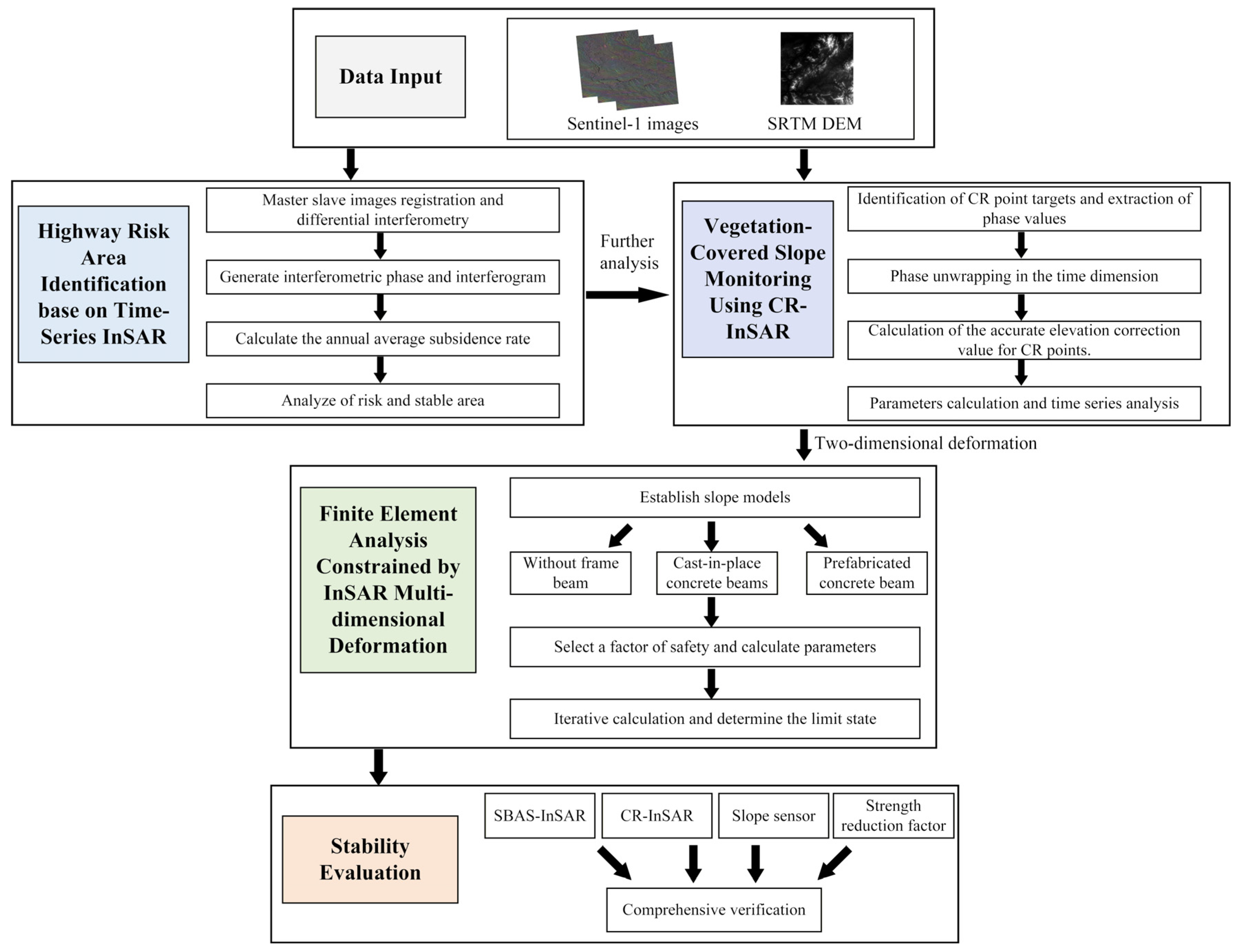
The flowchart of the proposed method in this paper is presented in Figure 2.
Figure 2.
The flowchart of the stability evaluation of vegetation-covered highway slopes using CR-InSAR and finite element simulation.
3. Results
3.1. Corner Reflector Recognition Experiment
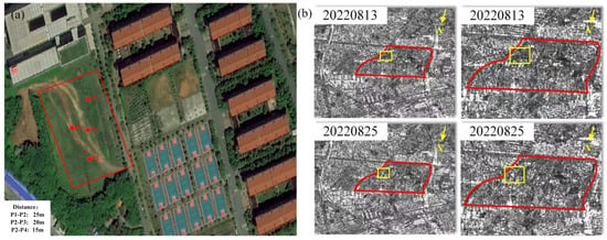
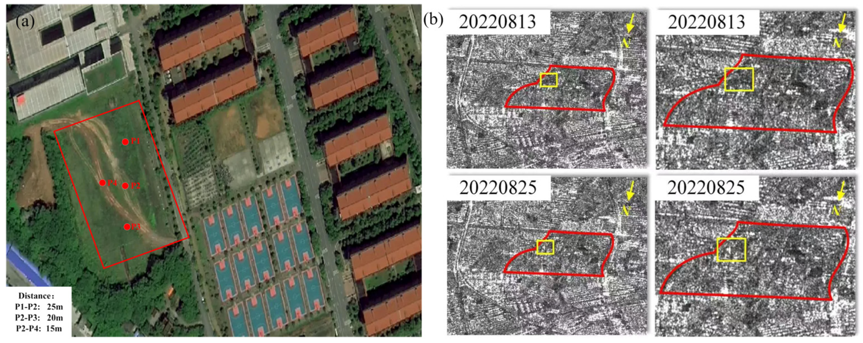
An experimental study was conducted at the Yuntang Campus of Changsha University of Science and Technology to ascertain the reasonable installation spacing of corner reflectors (CRs) on highway slopes. The experiment was performed with a multilook ratio of 1:1, with a pixel spacing of 2.32 m in range and 13.99 m in azimuth, and four CRs were arranged in the test field as illustrated in Figure 3. The experimental results show that all four CRs can be effectively recognized. Obvious mutual interference exists among P1, P2 and P3 at the azimuthal intervals of 15 m and 25 m, while P4 can be clearly distinguished from P2 at a range distance of 15 m. Therefore, it is determined that CRs on highway slopes should be arranged with an interval of more than 15 m in the range direction. This experimental conclusion provides a reliable basis for the layout of artificial CRs on the Guizhou–Huangping Expressway slope in the subsequent research.
Figure 3.
Identification of artificial reflectors in optical and SAR images. (a) Optical satellite image; (b) Sentinel-1 SLC SAR image. In subfigure (b), the red rectangle denotes the school area, and the yellow rectangle indicates the deployment range of corner reflectors.
3.2. Overview of the Experimental Area and Data
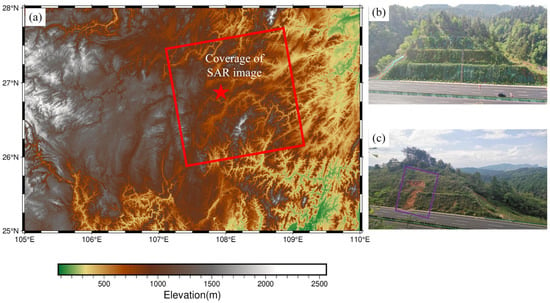
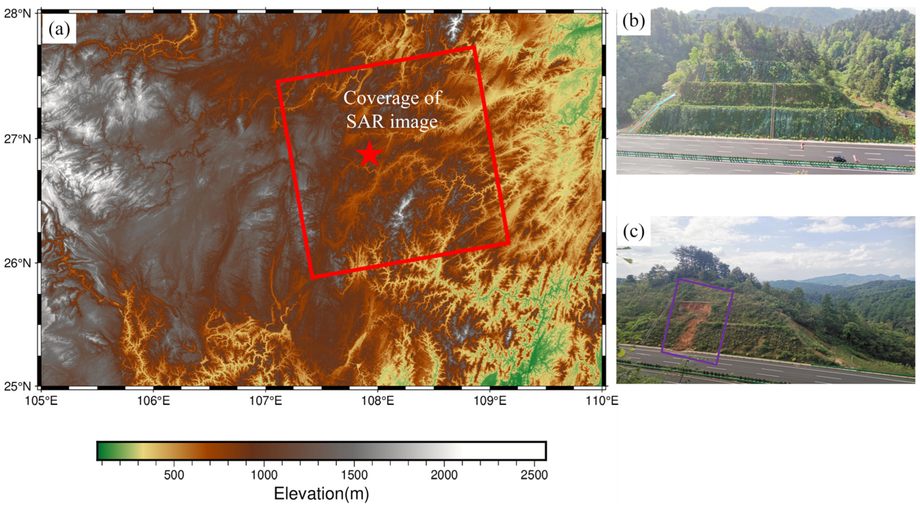
Guizhou Province is located in the southwestern region of China, with the geographical coordinates of 103°36′–109°35′E and 24°37′–29°13′N. The Guihuang highway has a total length of 120.6 km and passes through mountainous areas where landslides are frequent. Figure 4a depicts the coverage of the Sentinel-1A image as a red rectangle, while a red pentagram represents the study slopes of the Guihuang highway section K87 + 391.5–K87 + 565. As illustrated in Figure 4b, the height of the right side slope of the section is 35.8 m, and the support structure employs cast-in-place and prefabricated frame beams. As an artificially constructed slope designed in accordance with engineering drawings, its surface is regular and relatively flat with small undulations. The cast-in-place frame beams are supporting structures constructed completely on site. Formworks are erected and steel bars are arranged according to the slope design, and concrete is poured on site to form a rigid and integrated supporting system that fits the slope surface closely. The prefabricated frame beams are produced in factories in advance and then transported to the site for assembly and installation. Benefiting from the frame beam support, the slope exhibits insignificant deformation characteristics related to rainfall and freeze–thaw cycles. Figure 4c illustrates the lack of frame beam support on the left side slope of the section, which has experienced four significant instances of local sliding.
Figure 4.
Overview of topography and slopes in the study area. (a) Study slope (red pentagram) and SAR coverage (red rectangular); (b) The cast-in-place and prefabricated concrete frame beams supported the slope; (c) Landslides (purple rectangle) have occurred on an unsupported slope.
The study slope is located in a low mountainous, hilly area, where the surface vegetation is well-developed, predominantly shrubs and trees. The terrain is elevated to the east and depressed to the west, with an average ground elevation of 906.1–990.6 m and a relative elevation difference of approximately 84 m. Based on the stratum lithology as revealed by drilling, in conjunction with ground investigation and geotechnical testing, it can be concluded that the lithology of this road rift area can be divided into three engineering geological layers, in order from top to bottom:
- Red clay: The soil is brownish-yellow in color and exhibits relatively uniform quality, with a small amount of sand. The thickness of this layer varies from 0 to 11.8 m.
- Strongly weathered dolomite: the color is gray-yellow, the joints exhibit fissure development, the rock body is fractured to a significant extent, the rock quality is softer, the rock core is in the form of crushed blocks and medium and fine sand, and the thickness of the rock layer is approximately 6.1 to 6.6 m.
- Medium-weathering dolomite: The rock has a gray-white hue with slight joint development. The rock is more fractured and complex, with lumps, powder, and an acceptable sand core. This layer is situated beneath the strongly weathered dolomite layer. The red clay is distinguished by its weak expansion, high porosity ratio, high water content, high plasticity, and low compactness.
To ensure the regional applicability and reliability of the parameters for the studied slope, the principal physical and mechanical characteristics of the red clay were determined by combining laboratory geotechnical tests on in situ samples taken from the slope with a review of pertinent literature [29,30,31] and related engineering data, which are presented in Table 1. The above parameter acquisition method fully combines field test data and engineering experience, which ensures the rationality and reliability of the parameter values and meets the calculation requirements of slope strength reduction analysis.
Table 1.
Main indicators of physical and mechanical properties of red clay.
The prefabricated frame beam means that two joints are provided in the single girder between two adjacent anchor cables of the anchor cable frame beam, effectively dividing the conventional single girder into three sections. The first and last sections are crossbeams containing the anchor cables, while the center is a single beam. Instead of the traditional method of connecting the ends of the crossbeam in the field, this method uses a hinged structure to connect the ends of the crossbeam and the one-beam. This structure allows the prefabricated frame beams to adapt to certain deformations and release potential energy to avoid damage. The crossbeams and one-beams can be prefabricated using traditional materials or lightweight, high-strength, ecological, and environmentally friendly materials and assembled using mechanical lifting in on-site construction, thus reducing the number of personnel required on the slope and simplifying the construction process.
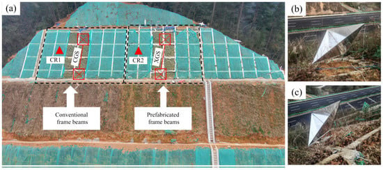
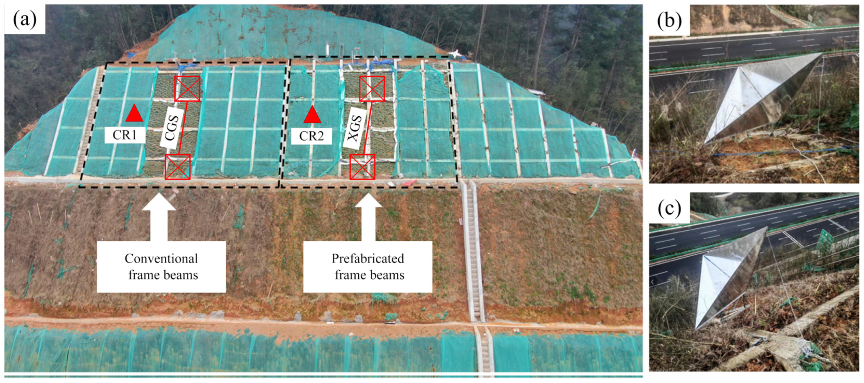
Furthermore, the assembly and laying of components can be conducted concurrently with the excavation process, thereby enabling the provision of slope support in a more timely manner and enhancing overall construction efficiency. Furthermore, the construction efficiency can be enhanced, the internal force distribution of the prefabricated frame beam structure is more optimal, and the support effect is comparable to that of the traditional anchor cable frame beam system. In the case of a high slope road graben with complex geological conditions and high potential hazards, it is impossible to ascertain the slope’s stability solely through theoretical analysis. In such instances, it is necessary to implement a dynamic monitoring system. Accordingly, various sensors are installed in the slope, including high-precision slope displacement gauges (cast-in-place frame beam and prefabricated frame beam are labeled CGS and XGS, respectively), and a strain gauge. All sensors used for field monitoring are professional geotechnical monitoring instruments and have been routinely calibrated before deployment. These sensors are buried in the slope to form an automatic detection system. Due to the limited geometric size of the highway slope, only two corner reflectors can be deployed. The orientation and installation angle of each CR are carefully designed according to the incident angle of the Sentinel-1 satellite corresponding to its coordinate position. The site plan of the corner reflector and some of the sensor arrangements are shown in Figure 5.
Figure 5.
Schematic diagram of the experimental slope and installation of corner reflectors and slope sensors. (a) Schematic layout of the experimental slope and sensors; (b) Installation of corner reflector CR1; (c) Installation of corner reflector CR2. In subfigure (a), triangles schematically mark the layout positions of corner reflectors, and rectangular boxes indicate the burial locations of slope sensors.
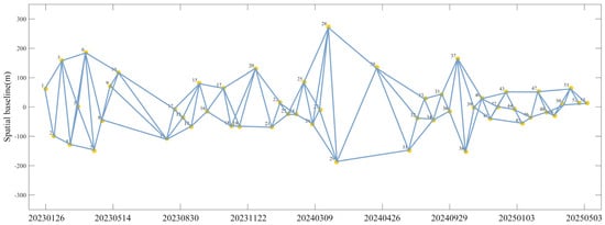
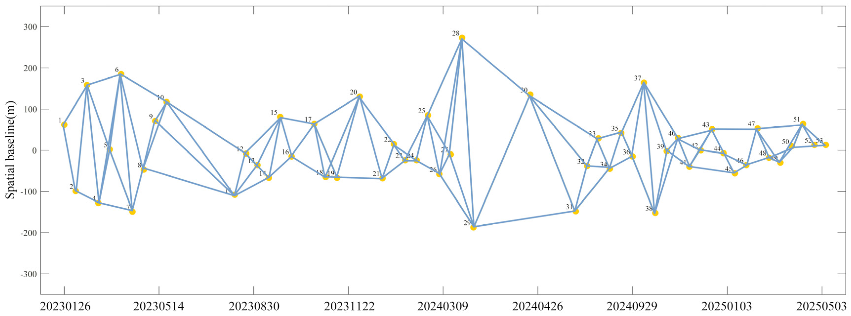
This study employed 54 Single Look Complex (SLC) images acquired by the European Space Agency’s (ESA) Sentinel-1A satellite, covering the target area from 26 January 2023 to 3 May 2025. The dataset features a C-band configuration with VV polarization, descending orbital geometry, and the incidence angle of 34° at the scene center. Detailed temporal and spatial baseline thresholds for SBAS-InSAR processing is systematically presented in Figure 6. To mitigate topographic phase contributions in interferogram generation, the Shuttle Radar Topography Mission (SRTM) Digital Elevation Model (DEM), accessible through NASA’s official data portal, was integrated as an external elevation reference.
Figure 6.
The spatiotemporal baseline distribution map for SBAS-InSAR.
3.3. InSAR Data Processing
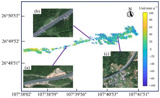
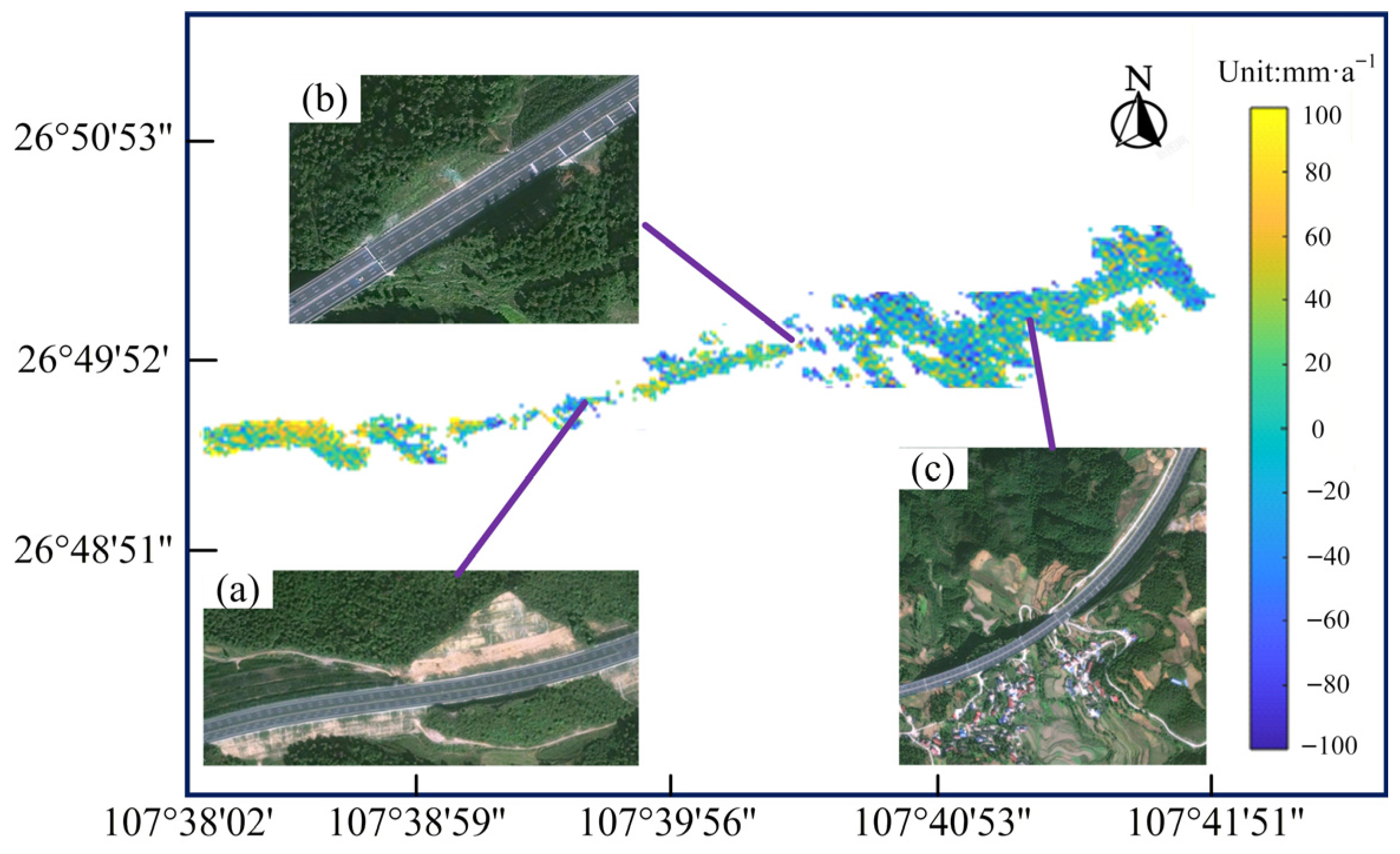
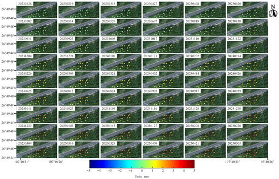
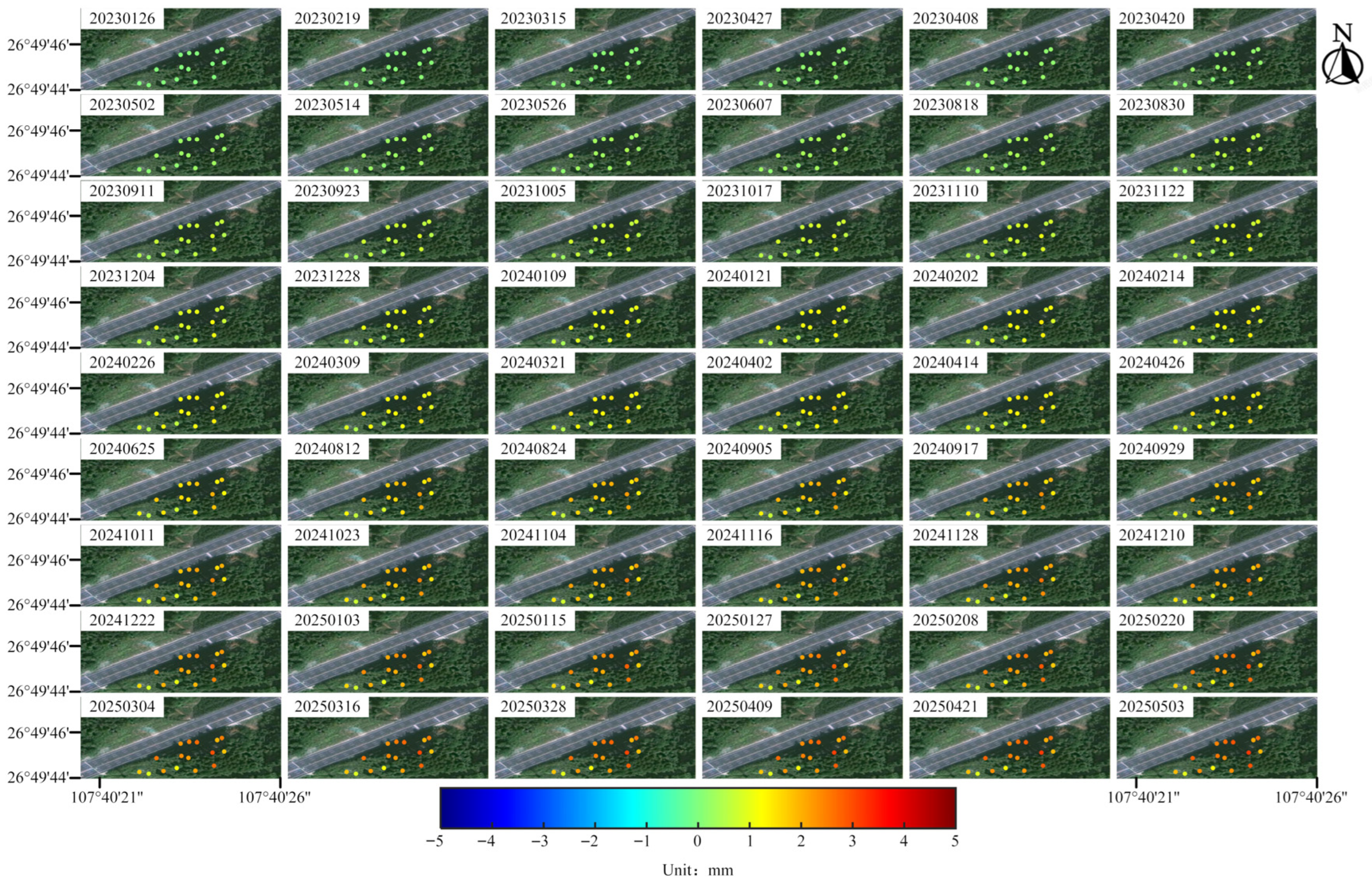
This investigation focuses on analyzing slope stability along the Guihuang highway through advanced InSAR techniques. The SBAS-InSAR methodology was first implemented to generate a regional deformation velocity map spanning the entire highway corridor. As illustrated in Figure 7a–c, distinct deformation patterns were identified across different geotechnical units: unreinforced pavement sections and adjacent natural slopes exhibited significant subsidence exceeding 40 mm·a−1, while off-highway structures demonstrated complex deformation signatures likely associated with differential settlement (Figure 7c). In stark contrast, the specifically engineered slope reinforced with composite frame beams (Figure 7b) showed remarkable stability, with deformation magnitudes constrained below 5 mm throughout the monitoring period, as evidenced by the time-series LOS displacement analysis in Figure 8.
Figure 7.
The InSAR deformation rate map of a section in the Guihuang highway. (a,c) represent slopes along the route; (b) indicates the study slope.
Figure 8.
Time-series InSAR deformation map of the slope within the K87 + 391.5–K87 + 565 section.
In this study, a specific slope along the Guihuang highway was reinforced with frame beams, leading to significantly reduced deformation compared to unreinforced sections of the highway. As previously detailed in the experimental methods, the SBAS-InSAR technique was applied for conventional deformation monitoring of the Guihuang highway. The overall deformation rate was estimated to be ±20–40 mm·a−1, with distinct deformation patterns observed across different slope segments; Figure 7a shows that the pavement and adjacent slopes without reinforcement exhibit settlement rates exceeding 40 mm/year; Figure 7c depicts substantial deformations in both road slopes and off-highway buildings. In contrast, the scientifically monitored slope in Figure 7b, which underwent frame beam reinforcement, demonstrates a markedly lower deformation rate.
While SBAS-InSAR proves effective for macroscopic deformation characterization across extensive areas, its performance becomes constrained in ecologically sensitive slopes with dense vegetation coverage. These constraints result in underestimated deformation rates and compromised spatial resolution in vegetated critical infrastructure zones.
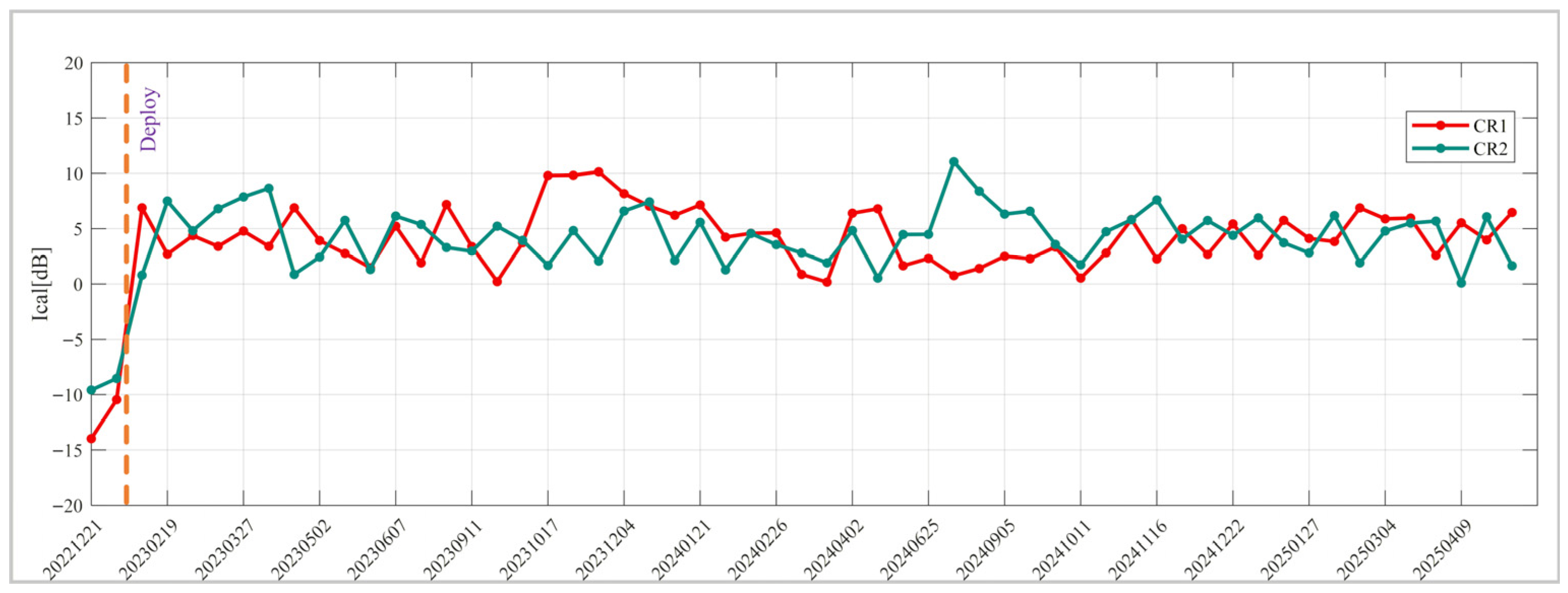
To address these limitations, a targeted Corner Reflector InSAR campaign was conducted on the frame beam-reinforced slope (Figure 7b). Artificial corner reflectors (CRs) were strategically deployed as permanent scatterers to achieve millimeter-level measurement precision. These CRs were installed in January 2023, and as shown in Figure 9, their deployment led to a significant enhancement in radar intensity—from approximately −10 dB to 7 dB—with subsequent stabilization of signal characteristics. To preserve the original image resolution, the multilook ratio for both range and azimuth directions was set to 1:1. Each CR point on the slope was extracted, and the line-of-sight deformation data were decomposed into vertical and horizontal components. The slope surface reinforced by frame beams is relatively flat with small curvature and weak local topographic fluctuations, so the influence of terrain factors on LOS deformation decomposition is negligible.
Figure 9.
Time series of radar intensity variations before and after the installation of CR1 and CR2.
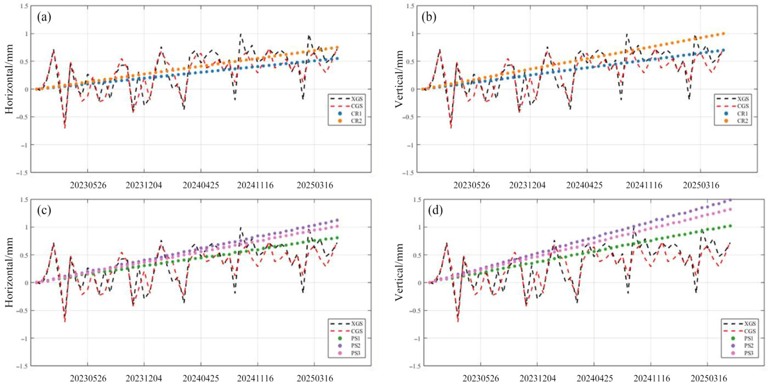
For comparison, we also selected several PS points on the slope and performed PS-InSAR processing. The results, as shown in Figure 10, are obviously inconsistent with the displacement records from on-site slope sensors, further indicating the inadequacy of conventional PS-InSAR in such vegetated slope areas.
Figure 10.
Comparison of displacements between InSAR results and slope sensor measurements (a) Horizontal displacement of CR; (b) Vertical displacement of CR; (c) Horizontal displacement of PS; (d) Vertical displacement of PS.
The correspondence between these decomposed displacements and the measurements from slope displacement sensors is illustrated in Figure 10, which also presents the time-series representation of deformation derived from this process. The layout scheme of CRs is designed and optimized according to the actual height, vegetation density of the studied slope and the radar incidence angle, which is well adaptable to the actual monitoring conditions of this project and similar slope engineering.
Figure 10 illustrates that the temporal deformation results for CR1 (cast-in-place frame beam) and CR2 (prefabricated frame beam) are approximately linear, indicating that both frame beams provide adequate slope support. The safety of the slope is reflected in its displacement, which is expected to change over time. Excavation of the slope disrupts the original stable condition, with mechanical vibrations capable of causing significant displacement changes. However, following the completion of excavation and the installation of slope protection measures, a period of dynamic adjustment occurs before the displacement stabilizes. The deformation of the CR point was verified using a wire displacement gauge on the side slope. The root mean square error (RMSE) of the horizontal and vertical displacements of the CR point on the cast-in-place frame beams was 0.27 and 0.24 mm, respectively. In contrast, the RMSE of the horizontal and vertical displacements of the CR point on the prefabricated frame beams was 0.23 and 0.26 mm, respectively. These results demonstrate better consistency. Over the years, no significant surface slips were observed, with the maximum surface displacement less than 1.5 mm, indicating a safe condition. The minimal difference in surface displacement between the two structures at the exact locations suggests comparable support effectiveness.
3.4. Finite Element Analysis
The finite element strength reduction method is a commonly used numerical technique for slope stability analysis. Its core principle is to gradually reduce the geotechnical mechanical parameters and iteratively calculate the slope displacement and plastic zone evolution until the model reaches a critical instability state, so as to determine the slope safety factor.
By the specified strength reduction factor conditions, the evolution of the plastic strain zone is depicted through a cloud diagram based on the pivotal physico-mechanical characteristics enumerated in Table 1. The slope is stable under the specified reduction factor without through or local yield damage. However, it can be unstable or damaged if the plastic strain increases excessively between adjacent iterative steps at specific nodes or if the generalized plastic strain reaches the yield limit. As evidenced by the results of the plastic strain display, the plastic strain zone has reached the top of the slope.
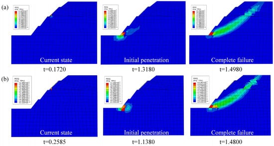
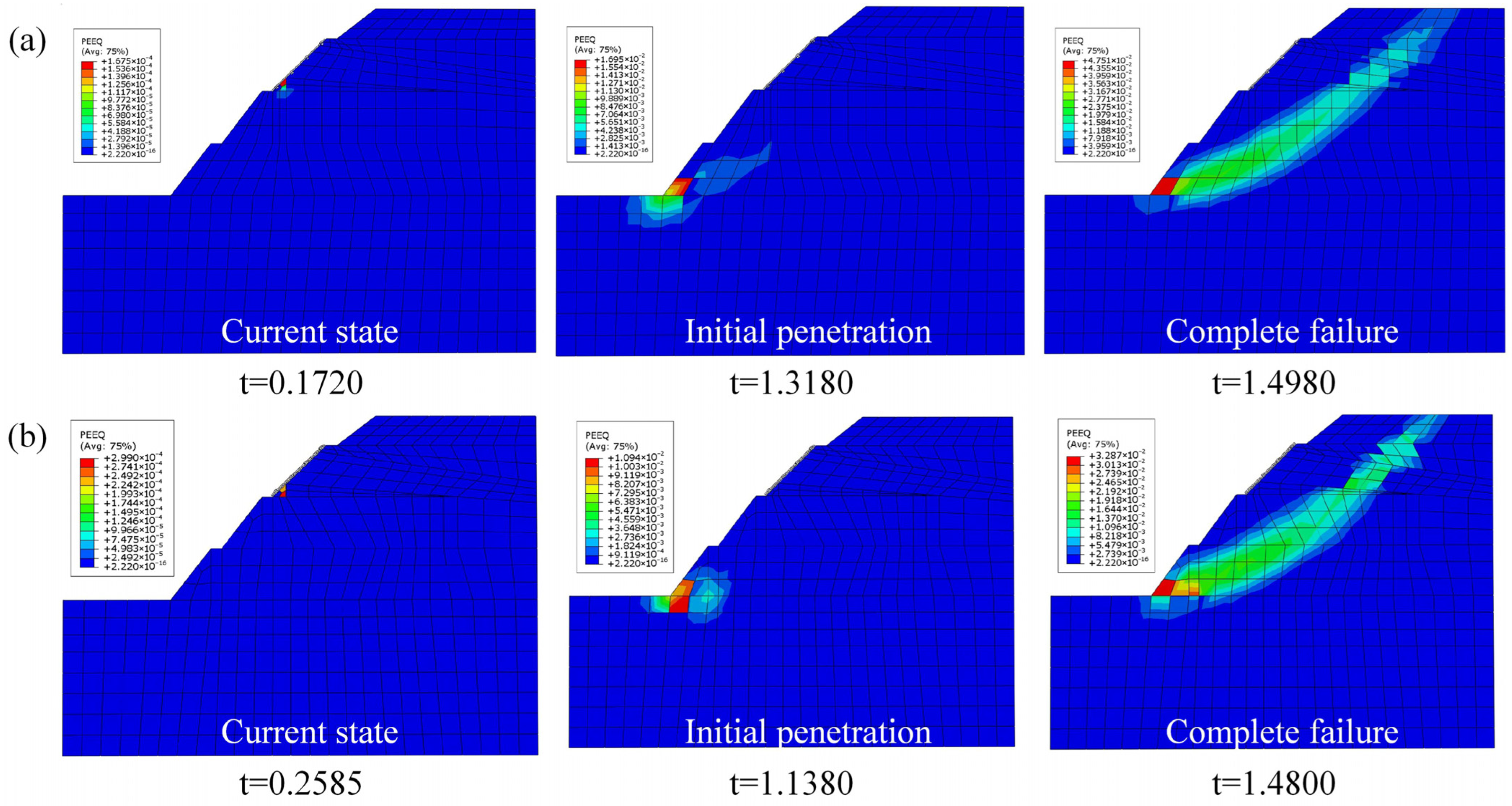
There is a discernible proclivity for the infinite development of the generalized plastic strain and displacement, accompanied by a pronounced abrupt transition, which signifies that the slope is in a critical damage state. The slope has reached a critical state of damage. Figure 11a depicts the equivalent plastic strain nephogram of the slope supported by the cast-in-place frame beam. The regions of plastic damage are indicated by values greater than 0. Here, t represents the normalized iteration ratio of the strength reduction factor (SRF) rather than actual time. The evolution of the plastic strain zone corresponds to the gradual increase in the strength reduction factor. At time point t = 1.318, the foot and upper part of the slope first exhibited plastic behavior, with the slope strength reduction factor increasing, leading to a gradual reduction in slope stability and extension of the plastic strain zone until t = 1.466, when the internal plastic strain zone of the slope reached a critical state.
Figure 11.
Nephogram of equivalent plastic strain zone. (a) cast-in-place concrete beams; (b) prefabricated concrete beams.
Additionally, the top of the frame beam in contact with the slope surface began to exhibit plastic behavior. This is attributed to the tensile forces exerted by the frame beam on the anchoring cable, which exerts pressure on the soil surface and results in the frame beam becoming detached from the soil. The soil on the slope’s surface is subjected to pressure, which results in yielding or damage. Figure 11b presents the equivalent plastic strain nephogram of the slope supported by the prefabricated frame beam. Additionally, at t = 1.318, the plastic strain zone emerges at the foot and upper part of the slope. Thereafter, the plastic strain zone gradually extends upward until t = 1.498, at which point it is critically penetrated. This is still accompanied by the top of the frame girder in contact with the slope surface of the soil, which is beginning to appear as a plastic zone.
A comparison of the above analyses reveals that the change rule of the plastic strain zone of the slope is identical in both the cast-in-place and the prefabricated concrete beams support scheme. In both cases, the plastic yield zone first appears at the foot and the upper part of the slope, and then the plastic strain zone of the slope gradually extends upward to complete penetration. Concurrently, the plastic strain zone appears on the contact surface between the frame beam and the slope.
To realize the combination of CR-InSAR monitoring data and strength reduction finite element analysis, the horizontal and vertical displacements monitored by CR are first interpolated onto the slope finite element mesh by spatial coordinate matching and point-by-node mapping. The interpolated displacement field is applied to the corresponding model nodes as initial displacement constraints in the strength reduction iterative process. During numerical iteration, convergence is judged by the displacement variation rate and unbalanced force ratio, and the displacement evolution at each strength reduction factor step is recorded in real time. The above numerical implementation ensures the rationality and traceability of the calculation process.
Furthermore, the displacements of CR were decomposed and inputted into the model at t = 0.1720 and t = 0.2585, respectively. These two moments correspond to the initial elastic deformation and early plastic development stages under the gradual strength reduction, which are completely consistent with the progressive iteration process of the strength reduction factor. These displacements did not reach the point of the beginning of penetration, thereby proving that the slope was in a very stable state after being supported by the cast-in-place or the prefabricated concrete beams.
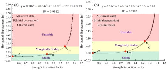
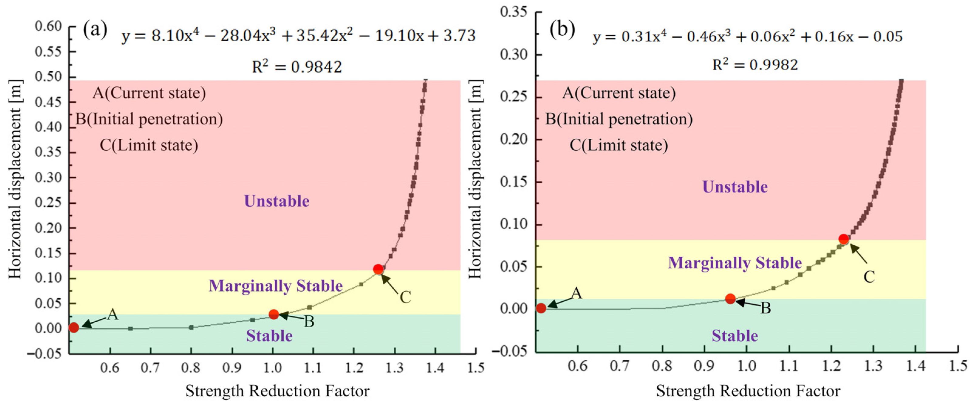
The coefficients are derived through the principle of least squares, and the fitted functional correlation coefficients are 0.9842 and 0.9982, respectively. The relationship curves between the horizontal displacements and the strength reduction factor after the cast-in-place and the prefabricated concrete beams supporting the slopes are presented in Figure 12. Figure 12 shows that when the strength reduction factor Ft reaches the point of most significant curvature in the figure (points C), the displacement begins to increase significantly. This indicates that the critical strength reduction factors of the slope supported by the cast-in-place and the prefabricated concrete beam are 1.28 and 1.22, respectively. The slight difference between these two critical strength reduction factors stems from their different structural systems. The cast-in-place frame beam is an integrated on-site pouring structure with better bonding and integrity with the slope soil. The prefabricated frame beam is a factory-produced and on-site assembled hinged structure with relatively lower overall stiffness. Both values are close and meet the requirements of relevant engineering slope stability codes.
Figure 12.
The relationship curve between horizontal displacement and strength reduction factor. (a) Cast-in-place concrete beams; (b) prefabricated concrete beams.
By substituting the horizontal displacements monitored by CR-InSAR into the fitted function, the current strength reduction factors (point A) of the slope are obtained as 0.11 and 0.12, which are much smaller than the values of 1.01 and 0.96 corresponding to initial penetration (point B). This result fully demonstrates that the slopes reinforced by the two types of frame beams are both in a stable state.
4. Discussion
This study takes the vegetation-covered highway slope in the mountainous areas of southwest China as the research object, obtains high-precision time-series deformation data of the slope sections supported by cast-in-place and prefabricated frame beams through CR-InSAR, and completes the slope stability evaluation combined with the strength reduction finite element method. The following systematic discussion is carried out around three aspects: the core value of the research results, the innovation and extensibility of the methodological system, and the research boundaries and prospects.
4.1. Academic and Engineering Value of the Core Research Findings
Through synchronous comparative monitoring of CR-InSAR and PS-InSAR, this study confirms that the slope deformation data obtained by CR-InSAR is in high agreement with the measured values of on-site wire displacement gauges, while the PS-InSAR results show obvious systematic deviations. The analysis shows that vegetation disturbance and atmospheric phase fluctuations induced by rainfall in southwest mountainous areas can easily lead to non-zero phase closure errors in PS-InSAR, which further causes accuracy loss in deformation inversion. In contrast, CR-InSAR relies on the stable high-amplitude scatterers of artificial corner reflectors, which can effectively avoid the impacts of vegetation decorrelation and phase closure errors. It has significant accuracy advantages and application reliability in the scenario of vegetation-covered mountain highway slopes, and can provide a direct reference for the selection of deformation monitoring technology in similar projects. Based on the high-precision CR-InSAR monitoring results, this study confirms that the time-series deformation laws of the slope sections supported by cast-in-place and prefabricated frame beams are highly consistent, and the deformation of both is within the millimeter-scale stable range throughout the whole monitoring period without abnormal instability characteristics, indicating that the reinforcement effects of the two support structures on the slope are basically equivalent. This conclusion has important practical guiding significance for the design and construction of highway slope support projects in mountainous areas: prefabricated frame beams can realize factory standardized prefabrication and on-site rapid assembly, eliminate the complex procedures of on-site formwork erection, steel bar binding, pouring and curing required by cast-in-place structures, greatly shorten the construction period and reduce labor and time costs, and can fully meet the safety requirements of slope support. More importantly, prefabricated frame beams can realize synchronized standardized deployment of corner reflectors during the slope construction phase, eliminating the need for road occupation and closure operations after highway opening to traffic, avoiding the safety risks and operational inconvenience of monitoring facility deployment during the operation period. It is more suitable for the core requirements of full-life cycle monitoring of highway slopes, and has favorable engineering promotion prospects.
4.2. Methodological System and Extensibility of the Coupled InSAR and Finite Element Analysis
At present, there is no unified standard for instability deformation threshold in the field of InSAR-based slope monitoring, and it is difficult to accurately and quantitatively determine the slope stability state only relying on measured deformation. Meanwhile, the traditional strength reduction finite element analysis mostly relies on the ideal geotechnical parameters obtained from laboratory tests, lacking constraints from field measured data, which easily leads to deviations between simulation results and the actual stress and deformation state of the slope. Aiming at this dual industry bottleneck, this study constructs a slope stability evaluation system with deep coupling of CR-InSAR measured deformation and finite element simulation: the LOS deformation obtained by CR-InSAR inversion is decomposed into two dimensions through slope aspect constraints, the horizontal displacement component highly correlated with the main controlling factor of slope instability is extracted, and fourth-order polynomial fitting is carried out between the horizontal displacement and the strength reduction factor to clarify the nonlinear evolution law of slope horizontal displacement with the change in the reduction factor. Meanwhile, the critical instability threshold of slope plastic coalescence is calibrated through finite element simulation, realizing accurate and quantitative determination of the slope stability state. This method not only corrects the parameter deviation of the finite element model through field measured deformation, improves the consistency between the simulation results and the engineering practice, but also fills the gap of the lack of quantitative instability criterion in InSAR monitoring through finite element simulation, forming a complete technical closed loop of “monitoring-simulation-determination”. It is not only applicable to the small-scale highway slope scenario in this study but also can be extended to the stability monitoring and safety evaluation of various artificial slopes such as railway, water conservancy and mine slopes.
4.3. Research Limitations, Scope of Applicability and Future Prospects
There are still some limitations and uncertainties in this study, which are objectively explained as follows: First, limited by the size of the slope in the study section, only 2 artificial corner reflectors are deployed. Although they are mainly set to compare the deformation differences in the two support structures, and the orientation and installation angle of the CRs are strictly designed to match the incident angle of the Sentinel-1A satellite to ensure the accuracy of the monitoring data, it is still impossible to fully characterize the spatial distribution characteristics of deformation across the whole slope surface. Second, limited by the installation time of CRs, the monitoring period of this study is about 2 years, which can only reflect the medium- and short-term deformation law and support effect of the slope, and there is still a certain limitation for the evaluation of the long-term service performance of the slope. Meanwhile, only Sentinel-1 satellite descending-only single-geometry observation data are available in the study area. Although the two-dimensional deformation decomposition is completed through slope aspect constraints to minimize the inversion deviation, there is still a certain degree of uncertainty. Third, the minor deformation fluctuations observed in summer may be affected by residual atmospheric errors and short-term heavy rainfall. In addition, the synchronous measured rainfall data are missing due to the damage of the on-site rain gauge by heavy rain, making it impossible to complete the accurate correlation analysis between deformation and rainfall. However, the rainfall-induced deformation characteristics of the slope under the protection of frame beam support are not significant, so this factor has a limited impact on the core conclusions of this study. Fourth, the finite element analysis in this study is based on widely accepted engineering assumptions such as the ideal elastoplastic Mohr-Coulomb strength criterion and homogeneity of stratum parameters, and reasonable simplification is made for the stratum structure and support structure details of the slope, which has a certain simplification deviation from the real geomechanical state of the slope. The technical system constructed in this study is mainly applicable to the medium- and short-term stability monitoring and support effect evaluation of small-scale artificial highway slopes with high vegetation coverage and complex terrain in karst mountainous areas of southwest China, and can also be extended to various artificial slope engineering projects with conditions for artificial corner reflector deployment. For natural slopes with ultra-large scale, extremely complex geological conditions and no conditions for stable high-amplitude scatterer deployment, the applicability of this method is limited. In the follow-up research, we will continue to carry out long-term slope monitoring relying on the permanently deployed corner reflectors to obtain longer time-series deformation data, and complete the comparative analysis of the long-term service performance of the two types of frame beams. Meanwhile, we will supplement multi-source environmental monitoring data and ascending-orbit satellite data, optimize the finite element numerical model, further improve the methodological system, and carry out multi-scale and multi-scenario application verification.
In summary, this study verifies the technical advantages of CR-InSAR in the monitoring of vegetation-covered mountain highway slopes, confirms the equivalent reinforcement effect and engineering adaptability of prefabricated frame beams and cast-in-place frame beams, and constructs a slope stability evaluation method constrained by measured deformation, which provides reliable technical support and engineering reference for the safety management and control and support structure selection of highway slopes in mountainous areas.
5. Conclusions
This study integrated the time-series InSAR and finite-element analysis method for stability assessment of vegetated highway slopes. A large-scale deformation monitoring based on the SBAS-InSAR was applied along the Guihuang highway to identify high-risk slopes. Subsequently, the CRs were installed on a slope (section K87 + 391.5–K87 + 565) to mitigate low interferometric coherence in densely vegetated regions. The CR deployment enhanced radar backscatter from −10 dB to 7 dB, accompanied by stabilized signal characteristics; additionally, the reinforced slope displayed LOS deformation less than 5 mm/y, with decomposed horizontal and vertical displacements no more than 1 mm, exhibiting strong consistency with slope monitoring sensors (RMSE less than 0.3 mm). Furthermore, the InSAR-constrained finite element strength reduction method shows that the current strength reduction factors are 0.11 and 0.12, which are far lower than the strength reduction factors of 1.28 and 1.22 for complete failure, which indicates that the cast-in-place and prefabricated frame beams demonstrated comparable support effectiveness.
This integrated workflow possesses clear automatic processing and batch analysis capabilities. The SBAS-InSAR technique allows batch large-scale deformation monitoring along the whole highway to automatically screen high-risk slopes. The CR-InSAR image processing, LOS deformation decomposition, and data import into the finite element model can be sequentially executed via script programming with little manual intervention, which enables efficient and batch stability evaluation. Such a technical characteristic provides strong support for the popularization and application of this method in mountainous highway engineering.
Author Contributions
Conceptualization, W.P., J.Z. (Jiachen Zhou) and J.Z. (Junhui Zhang); methodology, J.Z. (Junhui Zhang) and S.Z.; software, W.P. and J.Z. (Jiachen Zhou); validation, W.P., J.Z. (Jiachen Zhou) and J.Z. (Jun Zhu); formal analysis, X.X.; investigation, W.P.; resources, J.Z. (Junhui Zhang); data curation, W.P. and J.Z. (Jiachen Zhou); writing—original draft preparation, W.P.; writing—review and editing, W.P., J.Z. (Jun Zhu) and X.X.; supervision, W.P. and J.Z. (Junhui Zhang); funding acquisition, W.P., J.Z. (Junhui Zhang) and X.X. All authors have read and agreed to the published version of the manuscript.
Funding
This research was funded by the National Key R&D Program of China (Grant No. 2024YFB2605500), the National Natural Science Foundation of China (No. 42330717, and 42074033), and the Research and Innovation Projects for Postgraduates of Changsha University of Science and Technology (No. CLKYCX24009).
Data Availability Statement
The SRTM DEM is available from https://earthexplorer.usgs.gov/. The Sentinel-1A data is available from https://search.asf.alaska.edu/.
Acknowledgments
Many thanks to NASA and ESA for providing free datasets.
Conflicts of Interest
The authors declare no conflicts of interest.
References
- Tosti, F.; Gagliardi, V.; Ciampoli, L.B.; Benedetto, A.; Threader, S.; Alani, A.M. Integration of remote sensing and ground-based non-destructive methods in transport infrastructure monitoring: Advances, challenges and perspectives. In Proceedings of the 2021 IEEE Asia-Pacific Conference on Geoscience, Electronics and Remote Sensing Technology (AGERS), Jakarta Pusat, Indonesia, 29–30 September 2021; pp. 1–7. [Google Scholar]
- Zhu, L.J.; Xing, X.M.; Zhu, Y.K.; Peng, W.; Yuan, Z.H.; Xia, Q. An advanced time-series InSAR approach based on poisson curve for soft clay highway deformation monitoring. IEEE J. Sel. Top. Appl. Earth Obs. Remote Sens. 2021, 14, 7682–7698. [Google Scholar] [CrossRef] [Scilit]
- Fruneau, B.; Achache, J.; Delacourt, C. Observation and modelling of the Saint-Etienne-de-Tinée landslide using SAR interferometry. Tectonophysics 1996, 265, 181–190. [Google Scholar] [CrossRef] [Scilit]
- Ferretti, A.; Prati, C.; Rocca, F. Nonlinear subsidence rate estimation using permanent scatterers in differential SAR interferometry. IEEE Trans. Geosci. Remote Sens. 2002, 38, 2202–2212. [Google Scholar] [CrossRef] [Scilit]
- Berardino, P.; Fornaro, G.; Lanari, R.; Sansosti, E. A new algorithm for surface deformation monitoring based on small baseline differential SAR interferograms. IEEE Trans. Geosci. Remote Sens. 2003, 40, 2375–2383. [Google Scholar] [CrossRef] [Scilit]
- Strozzi, T.; Farina, P.; Corsini, A.; Ambrosi, C.; Thüring, M.; Zilger, J.; Wiesmann, A.; Wegmüller, U.; Werner, C. Survey and monitoring of landslide displacements by means of L-band satellite SAR interferometry. Landslides 2005, 2, 193–201. [Google Scholar] [CrossRef] [Scilit]
- Nikolaeva, E.; Walter, T.; Shirzaei, M.; Zschau, J. Landslide observation and volume estimation in central Georgia based on L-band InSAR. Nat. Hazards Earth Syst. Sci. 2014, 14, 675–688. [Google Scholar] [CrossRef] [Scilit]
- Xue, F.Y.; Lv, X.L.; Dou, F.J.; Yun, Y. A review of time-series interferometric SAR techniques: A tutorial for surface deformation analysis. IEEE Geosci. Remote Sens. Mag. 2020, 8, 22–42. [Google Scholar] [CrossRef] [Scilit]
- Li, T.; Tang, X.M.; Li, S.J.; Zhou, X.Q.; Zhang, X.; Xu, Y.Z. Classification of basic deformation products of L-band differential interfero-metric SAR satellite. Acta Geod. Cartogr. Sin. 2023, 52, 769. [Google Scholar]
- Xia, Z.G.; Motagh, M.; Li, T. Performance analysis of dihedral corner reflectors for slope movements: A case study from Aniangzhai landslide in China. IEEE Geosci. Remote Sens. Lett. 2022, 19, 4515605. [Google Scholar] [CrossRef] [Scilit]
- Quin, G.; Loreaux, P. Submillimeter accuracy of multipass corner reflector monitoring by PS technique. IEEE Trans. Geosci. Remote Sens. 2012, 51, 1775–1783. [Google Scholar] [CrossRef]
- Liu, H.; Zhou, B.C.; Miao, C.W.; Li, S.H.; Xu, L.; Zheng, K.; Li, G.S.; Yang, S.J.; Zhu, M.Y. Refinement analysis of real dihedral and trihedral CR-InSAR based on TerraSAR-X and Sentinel-1A images. IEEE J. Sel. Top. Appl. Earth Obs. Remote Sens. 2024, 17, 18739–18750. [Google Scholar] [CrossRef] [Scilit]
- Singleton, A.; Li, Z.; Hoey, T.; Muller, J.-P. Evaluating sub-pixel offset techniques as an alternative to D-InSAR for monitoring episodic landslide movements in vegetated terrain. Remote Sens. Environ. 2014, 147, 133–144. [Google Scholar] [CrossRef] [Scilit]
- Zhu, W.; Zhang, Q.; Ding, X.L.; Zhao, C.Y.; Yang, C.S.; Qu, F.F.; Qu, W. Landslide monitoring by combining of CR-InSAR and GPS techniques. Adv. Space Res. 2014, 53, 430–439. [Google Scholar] [CrossRef] [Scilit]
- Zienkiewicz, O.; Lyness, J.; Owen, D. Three-dimensional magnetic field determination using a scalar potential—A finite element solution. IEEE Trans. Magn. 1977, 13, 1649–1656. [Google Scholar] [CrossRef] [Scilit]
- Griffiths, D.; Lane, P. Slope stability analysis by finite elements. Geotechnique 1999, 49, 387–403. [Google Scholar] [CrossRef] [Scilit]
- Zhao, S.; Zheng, Y.; Shi, W.; Wang, J. Analysis on safety factor of slope by strength reduction FEM. Chin. J. Geotech. Eng. 2002, 24, 343–346. [Google Scholar] [CrossRef]
- Zhao, S.Y.; Zheng, Y.R.; Deng, W.D. Stability analysis on jointed rock slope by strength reduction FEM. Chin. J. Rock Mech. Eng. 2003, 22, 254–260. [Google Scholar] [CrossRef]
- Zheng, Y.R.; Zhao, S.Y. Application of strength reduction FEM in soil and rock slope. Chin. J. Rock Mech. Eng. 2004, 23, 3381–3388. [Google Scholar]
- Luan, M.T.; Wu, Y.J.; Nian, T.K. A criterion for evaluating slope stability based on development of plastic zone by shear strength reduction FEM. J. Disaster Prev. Mitig. Eng. 2003, 23, 1–8. [Google Scholar]
- Yang, C.; Wang, S.J.; Feng, T.G. Study on slope’s failure criterion based on the development of plastic zone. China Sci. Pap. 2016, 11, 1461–1464. [Google Scholar]
- Wang, S.Y.; Tong, X.D. Stability analysis of slopes based on dynamic strength reduction improved vector sum method. Chin. J. Geotech. Eng. 2023, 45, 1384–1392. [Google Scholar] [CrossRef]
- Liu, F.; Yang, Z.; Li, Q.L. The slope stability analysis based on the finite element numerical simulation. In Proceedings of the 2022 International Conference on Cloud Computing, Big Data and Internet of Things (3CBIT), Wuhan, China, 22–23 October 2022; pp. 11–14. [Google Scholar]
- Chiu, H.-W.; Hsu, C.-F.; Chen, S.-L. Analysis of Parameters of National Highway Slope Protection Project under Dynamic Behavior by Finite Element Method. In Proceedings of the 2023 IEEE 5th International Conference on Architecture, Construction, Environment and Hydraulics (ICACEH), Taichung, Taiwan, 1–3 December 2023; pp. 32–37. [Google Scholar]
- Zebker, H.A.; Rosen, P.A.; Goldstein, R.M.; Gabriel, A.; Werner, C.L. On the derivation of coseismic displacement fields using differential radar interferometry: The Landers earthquake. J. Geophys. Res. Solid Earth 1994, 99, 19617–19634. [Google Scholar] [CrossRef] [Scilit]
- Shi, G.L.; Chen, Q.; Liu, X.W.; Yang, Y.H.; Xu, Q.; Zhao, J.J. Deformation velocity field along aspect direction of an ancient landslide at Taoping village derived from ascending and descending Sentinel-1A data. J. Eng. Geol. 2022, 30, 1350–1361. [Google Scholar]
- Xu, J.Q.; Xu, L.Q.; Zhang, G.C. Study of Slope Instability Criterion Based on Total Displacement Mode Mutation. Water Resour. Power 2023, 41, 143–146+129. [Google Scholar] [CrossRef]
- Cui, X.; Zhang, L.J.; Zhai, Y.F.; Ma, T.X.; He, L. Research on dynamic instability mechanism of slopes based on plastic strain energy theory. Yangtze River 2020, 51, 180–183. [Google Scholar] [CrossRef]
- Sun, D.A.; Gao, Y.; Liu, W.J.; Wei, C.F.; Zhang, S. Soil-water characteristics and pore-size distribution of lateritic clay. Chin. J. Geotech. Eng. 2015, 37, 351–356. [Google Scholar]
- Mu, K.; Kong, L.W.; Zhang, X.W.; Yin, S. Experimental investigation on engineering behaviors of red clay under effect of wetting-drying cycles. Rock Soil Mech. 2016, 37, 2247–2253. [Google Scholar]
- Liang, C.Y.; Zhang, H.; Wang, T. Red clay/mudstone distribution, properties and loess–mudstone landslides in the Loess Plateau, China. Environ. Earth Sci. 2022, 81, 386. [Google Scholar] [CrossRef] [Scilit]

Disclaimer/Publisher’s Note: The statements, opinions and data contained in all publications are solely those of the individual author(s) and contributor(s) and not of MDPI and/or the editor(s). MDPI and/or the editor(s) disclaim responsibility for any injury to people or property resulting from any ideas, methods, instructions or products referred to in the content. |
© 2026 by the authors. Licensee MDPI, Basel, Switzerland. This article is an open access article distributed under the terms and conditions of the Creative Commons Attribution (CC BY) license.