


Abstract
Ethylene tetrafluoroethylene (ETFE) foil is an ultralightweight fluoropolymer membrane covering large-span structures, yet the environmental impacts of its recycling remain largely unquantified. This study assesses an experimental recycling pathway in which 2235 kg of post-consumer ETFE foil, recovered from the Chelsea and Westminster Hospital in London after 33 years, was cleaned, agglomerated, pelletised and extruded into foil with 100% recycled content. The life cycle assessment follows ISO 14040/14044, applies EN 15804+A2 and the cumulative energy demand, and adopts an end-of-life-to-gate boundary under the cut-off approach, with 1 kg of recycled foil as the functional unit. The calculated material yield, based on adopted process-loss values, is 93.7%. Producing 1 kg of recycled foil results in a fossil global warming potential of 3.33 kg CO2 eq. and a cumulative energy demand of 64.1 MJ, of which 80% is non-renewable. Pelletisation, agglomeration electricity, road transport from London to Bremen and foil extrusion account for 70% of the fossil global warming potential. Scenario analysis, dominated by the proxy datasets for pelletisation and extrusion, yields a GWP-fossil range of 2.63–5.17 kg CO2 eq. These values are lower than those published for the GWP of virgin ETFE foil (12.0–20.9 kg CO2 eq.), highlighting the promising environmental potential of closed-loop recycling, which a harmonised comparison would confirm.
1. Introduction
The buildings and construction sector accounts for approximately 37% of global carbon dioxide (CO2) emissions [1], while the built environment is responsible for approximately 50% of all materials extracted in the European Union [2]. In response, the European Commission’s Circular Economy Action Plan promotes resource efficiency and material circularity throughout the building life cycle [2]. Furthermore, the recast Energy Performance of Buildings Directive (EU) 2024/1275 requires the life cycle global warming potential (GWP) of new buildings to be calculated and disclosed. The requirement applies to buildings with a useful floor area exceeding 1000 m2 from 1 January 2028 and to all new buildings from 1 January 2030 [3].
Within this context, architectural membranes, including technical textiles and foils, offer opportunities to cover large spans with relatively low material consumption. Ethylene tetrafluoroethylene (ETFE) foil is one such lightweight fluoropolymer membrane with an area mass of less than 1 kg/m2 [4], used predominantly in pneumatically prestressed cushion systems for roofs and façades [5]. Despite its low area mass, ETFE has a substantial embodied energy, and previous assessments have identified raw material production and polymerisation as major contributors to its production-related energy demand [6,7]. Recovering and recycling ETFE foil at the end of its service life could therefore retain the polymer within the material cycle and potentially reduce the demand for virgin feedstock, provided that the recycled material meets the requirements of its intended application. The durability of ETFE foil is illustrated by the cushion roof of the Chelsea and Westminster Hospital in London, which was installed in 1990 and dismantled during refurbishment in 2023, after 33 years of service [8,9]. The foil reclaimed from this roof forms the basis of the present investigation.
Recent research has extended the application of life cycle assessment (LCA) to architectural membranes and lightweight building envelopes, with increasing attention to material efficiency, adaptability and circularity. Monticelli [10] examined the integration of LCA into membrane design, emphasising material optimisation and life cycle considerations. Lamnatou et al. [11] and Li et al. [12] investigated the environmental impacts of ETFE-based and textile-integrated photovoltaic façade systems and highlighted the influence of system configuration and electricity supply. Borschewski et al. [13] evaluated LCA results for adaptive multilayer membrane façades, focusing on environmental hotspots and parameter sensitivity. Bal and Yılmaz [14] compared the environmental impacts of ETFE pneumatic systems and PVC tensile façades with those of conventional envelope materials. In parallel, Eryuruk et al. [15] investigated the environmental implications of reusing temporary membrane structures and identified the influence of repeated use and transport. Monticelli et al. [16] examined end-of-life valorisation strategies for tensioned membrane structures, addressing circular economy principles, design for disassembly, and the reuse and recycling of PVC-coated polyester fabrics, PTFE-coated glass fabrics and ETFE foils. Collectively, these studies have advanced the environmental assessment of lightweight building envelopes and demonstrated the relevance of material selection, system configuration and circular design strategies. However, they predominantly concern complete building systems, façade configurations or structural reuse, rather than the individual operations required to recover and reprocess post-consumer architectural membrane materials.
The environmental impacts reported for architectural ETFE foil systems vary considerably across published Environmental Product Declarations (EPDs). For the production stage (A1–A3), six declarations report GWP or GWP-total values ranging from 36.8 to 207 kg CO2 eq. per m2. Their total primary energy use, calculated as the sum of renewable (PERT) and non-renewable (PENRT) primary energy resources, ranges from approximately 579 to 1222 MJ/m2 [4,17,18,19,20,21]. These declarations refer to the ETFE foil cushion system, which includes aluminium clamping profiles, sealing materials, valves and fabrication processes in addition to the foil. Among the aforementioned EPDs, a representative ETFE foil cushion mass of approximately 0.88 kg/m2 is reported, although this value varies depending on the number and thickness of foil layers and the specific system configuration. Consequently, the variations in reported environmental impacts are influenced by differences in product configuration, material composition, geographical and temporal representativeness, background datasets, life cycle impact assessment (LCIA) methods and modelling assumptions. Therefore, a meaningful comparison of these results would require methodological harmonisation, including consistent system boundaries, functional units, LCIA methods and modelling assumptions, together with the separation of the environmental impacts attributable to the ETFE foil from those associated with the complete system. Environmental data relating specifically to virgin ETFE foil are more limited. Table 1 summarises two manufacturer-specific LCAs, referred to as ETFE A and ETFE B, representing European and Japanese production, respectively [22,23]. ETFE A was published in 2017 and is based on production data from 2012, whereas ETFE B was published in 2017–2018 and is based on production data from 2014. Both assessments report cradle-to-gate environmental impacts for modules A1–A3 under the EN 15804 [24] framework, with CML-based [25] impact indicators, covering raw material production, transport, packaging and foil manufacturing. The reported results are expressed per declared unit of 1 kg of virgin ETFE foil to facilitate their presentation.
Table 1.
Comparison of selected environmental impact and resource-use indicators for the cradle-to-gate production stage (A1–A3) of virgin ETFE foils [22,23].
The two assessments report GWP values of 12.0 and 20.9 kg CO2 eq. per kg of virgin foil and a total primary energy use of approximately 231 and 312 MJ/kg, respectively. Although these results provide material-specific environmental information, their comparability is limited by differences in manufacturing conditions, geographical representativeness, background inventories and the transparency of the underlying modelling assumptions. Neither document reports an independent third-party verification. Furthermore, their EN 15804 [24] impact indicators differ from those adopted under EN 15804+A2 [26]. These results provide a reference for establishing a comparative assessment of the environmental burdens associated with virgin and post-consumer recycled ETFE foil production, while accounting for differences in system boundaries, methodological approaches and modelling assumptions.
The end-of-life management of fluoropolymers presents additional challenges. Améduri and Hori [27] reviewed recycling and treatment pathways for fluoropolymers, including mechanical reprocessing, chemical recycling and thermal treatment, together with the associated technical and environmental considerations. For architectural ETFE foil, the suitability of recovered material for subsequent applications depends on its composition, its contamination and the mechanical and optical properties required. The proposed restriction of per- and polyfluoroalkyl substances under the REACH Regulation, whose broad scope also encompasses fluoropolymers, further highlights the relevance of material management and circularity, and the need for environmental assessments of recovery pathways such as the one investigated in this study [28].
The existing literature reveals two principal research gaps. First, previous studies have primarily examined virgin ETFE production, standard cushion systems, end-of-life scenarios and the technical feasibility of recycling, whereas the environmental contributions of the individual operations involved in reprocessing post-consumer architectural ETFE foil into new foil have yet to be characterised in detail. Moreover, as ETFE-specific life cycle inventory datasets for pelletisation and foil extrusion are scarce, proxy processes are required, and their influence on the calculated environmental impacts needs to be evaluated systematically. Second, the available environmental data for virgin ETFE foil provide a useful reference for indicators such as global warming potential and fossil resource depletion; however, differences in background inventories, allocation assumptions and impact assessment methods limit their direct comparability with recycled foil production across all indicators.
The present study addresses these limitations through a case-specific LCA of an experimental industrial pathway for the mechanical recycling of post-consumer architectural ETFE foil. It forms part of a broader research project assessing the feasibility of reintroducing post-consumer recycled (PCR) ETFE foil into architectural systems for the façade retrofitting of tertiary buildings, through the characterisation of its mechanical and optical behaviour. The transparent foil recovered from the Chelsea and Westminster Hospital roof was processed into new ETFE foil containing 100% PCR material. The recovered printed foil followed a separate downcycling pathway and was excluded from the assessment. The present investigation follows ISO 14040 and ISO 14044 [29,30], applies the EN 15804+A2 impact assessment method [26] together with the cumulative energy demand (CED) [31], and adopts an end-of-life-to-gate system boundary under the cut-off approach. The assessment uses a mass-based functional unit of 1 kg of finished PCR ETFE foil at the factory gate. The study addresses three research questions:
RQ1: What are the environmental impacts of producing 1 kg of PCR ETFE foil through the investigated recycling pathway?
RQ2: Which processes and inventory parameters contribute most to these impacts, and how sensitive are the results to the available data and modelling assumptions?
RQ3: How do the results relate to the published environmental data for virgin ETFE foil, and which methodological conditions would be required for a quantitative comparison?
Building on the previously documented recycling workflow [8], the study develops a process-based life cycle inventory that distinguishes measured, company-specific, literature-derived, estimated and proxy data. It quantifies the contributions of the individual recycling operations, identifies the principal environmental hotspots and evaluates the influence of selected inventory assumptions through sensitivity and scenario analyses. The findings provide case-specific evidence of the environmental burdens associated with the recycling of post-consumer architectural ETFE foil and identify the data and methodological requirements for future comparative assessments. Section 2 describes the materials and methods, Section 3 presents and discusses the results, Section 4 summarises the conclusions and Section 5 sets out the limitations and directions for future research.
2. Materials and Methods
2.1. Industrial Case Study: Chelsea and Westminster Hospital ETFE Roof
The Chelsea and Westminster Hospital in London was the first building in the United Kingdom to incorporate an ETFE cushion roof, installed by Vector Foiltec GmbH, Bremen, Germany in 1990 over approximately 4200 m2 of atria and internal streets. The success of this project contributed to the wider adoption of ETFE cushion systems in urban buildings [5]. After 33 years in service, the roof was dismantled during refurbishment in 2023, yielding 2444 kg of reclaimed ETFE foil, of which 2235 kg was transparent and 209 kg was printed [8]. The printed foils were not included in the experimental process; instead, they followed the established recycling route of Vector Foiltec GmbH, in which reclaimed ETFE is downcycled into ETFE valves and flexible pipes [4]. The present study therefore focuses on the transparent fraction, which underwent an experimental cleaning process at Fietz® Polychromos GmbH, Burscheid, Germany (Fietz Polychromos), where it was subsequently agglomerated and pelletised, before being extruded into foil by NOWOFOL® Kunststoffprodukte GmbH & Co. KG, Siegsdorf, Germany (Nowofol), as illustrated in Figure 1. Although several recycled–virgin ETFE formulations were produced during the extrusion trials, the life cycle assessment deliberately models only foil manufactured from 100% post-consumer recycled ETFE, with no addition of virgin polymer. This choice was made to assess the environmental impacts of the recycling pathway in isolation: including a virgin fraction would have introduced the burdens of primary ETFE production and made the results dependent on an arbitrary blend ratio. The study thus presents a case-specific life cycle assessment of an experimental industrial pathway for the post-consumer recycling of architectural ETFE foils, in which 2235 kg of reclaimed transparent foil yielded 2094.98 kg of finished recycled foil.
Figure 1.
Schematic representation of the mechanical recycling pathways for post-consumer ETFE foils.
2.2. Goal and Scope Definition
2.2.1. Goal of the Study
The goal of this study is to assess the environmental impacts of the mechanical recycling of post-consumer ETFE foils recovered from the Chelsea and Westminster Hospital in London. Specifically, the assessment aims to quantify the environmental impacts and CED associated with converting reclaimed ETFE foil into PCR ETFE foil, and to identify the processes that contribute most to these impacts. The study is intended to support research and development in ETFE recycling, to inform manufacturers and designers of the environmental implications of post-consumer material recovery and to provide a basis for future life cycle assessments of recycled ETFE in architectural applications. The results refer to the production stage of PCR ETFE foil only; comparisons with virgin ETFE are indicative and are not intended as comparative assertions disclosed to the public within the meaning of ISO 14044. The LCA follows the principles and framework established in ISO 14040 and the requirements and guidelines specified in ISO 14044.
2.2.2. Functional Unit
The functional unit is defined as 1 kg of finished post-consumer recycled (PCR) ETFE foil, produced from reclaimed post-consumer ETFE foil through cleaning, agglomeration, pelletisation and extrusion, with a recycled content of 100% and no addition of virgin polymer. As the function of the foil within a building is not defined and the use stage is excluded from the system boundary, the functional unit is equivalent to a declared unit in the sense of EN 15804:2012+A2:2019 [26] and refers to the material output at the factory gate. The technical suitability of the PCR ETFE foil for architectural applications is not assessed in this study. All inventory data and results are expressed per functional unit.
2.2.3. System Boundary and Cut-Off Criteria
The present study adopts an end-of-life-to-gate system boundary to assess the environmental impacts of the recovery and mechanical recycling of post-consumer ETFE foil, as illustrated in Figure 2. The system boundary begins with the end of life of the original ETFE foil, namely its dismantling at the Chelsea and Westminster Hospital in London, United Kingdom, and ends with the production of PCR ETFE foil at the extrusion facility in Siegsdorf, Germany. In terms of the structure of EN 15804+A2, the system spans the end-of-life stage of the original foil (modules C1–C3: dismantling, transport and waste processing) and the product stage of the PCR ETFE foil (modules A1–A3). The investigated pathway comprises packaging of ETFE foil scrap on site, transport to the Vector Foiltec GmbH facility in Bremen, Germany, manual sorting, transport to the recycling facility, manual cutting and inspection, washing, drying, agglomeration, pelletisation, intermediate packaging and storage, transport to the extrusion facility and foil extrusion. The inputs considered for these stages include electricity, water, detergent, packaging materials and transport, together with the treatment of process wastewater, material losses and packaging waste. The assumptions and data sources adopted for the individual stages are described in Section 2.4. In accordance with the cut-off allocation approach described in Section 2.2.4, the production, installation and use of the original ETFE foil lie outside the system boundary, as do all subsequent life cycle stages of the PCR ETFE foil, from installation to end-of-life treatment. The assessment is limited to the ETFE foil itself; the supporting structure and other components of the original cushion roof are not considered. The 209 kg of printed foil recovered from the roof did not enter the investigated pathway and is therefore not included. The results thus represent the environmental impacts of producing PCR ETFE foil from post-consumer material, rather than those of its complete life cycle in an architectural application.
Figure 2.
System boundary for LCA modelling of post-consumer recycling of ETFE foils.
The cut-off criteria of EN 15804+A2 served as the reference for the inclusion of flows. Capital goods are included to the extent that they are represented in the ecoinvent background datasets [32,33], as the model was calculated with infrastructure processes included; this covers, for example, electricity generation and distribution, transport vehicles and road infrastructure, and the production facilities of the pelletising and extrusion datasets. The equipment used for washing, drying and agglomeration was not modelled, as these operations are represented by their energy and water inputs only and the share of the equipment’s production attributable to a single batch is expected to be small. Personnel-related activities, such as staff travel and administration, were excluded. Empty return trips of the transport vehicles are accounted for through the average load factors of the ecoinvent lorry transport datasets.
2.2.4. Allocation Approach
The cut-off allocation approach was applied using the Allocation, cut-off by classification, U system model of the ecoinvent database. Under this approach, the reclaimed ETFE foil enters the system free of the burdens of its original production, installation and use, while all burdens arising from its recovery and reprocessing are attributed to the PCR ETFE foil. The cut-off approach was selected because it reflects the polluter-pays principle underlying EN 15804 and corresponds to the system model of the background database. Alternative allocation approaches, which distribute burdens across successive life cycles, may lead to different results; this is discussed in Section 3.5.
The reusable timber crates used for storage and transport were allocated over an assumed number of ten use cycles, and a single-use scenario is considered in the sensitivity analysis. The biogenic carbon stored in the crates is reported separately as GWP-biogenic and is regarded as temporarily stored in the technosphere during reuse. The corrugated cardboard octabins used for pellet storage were retained at the extrusion facility for further use; no end-of-life treatment was therefore attributed to them, while their production was conservatively allocated in full to the functional unit. The PE packaging film, in contrast, is single-use and was assumed to be treated by municipal incineration after unpacking. Inventory data recorded for the processing of the 2235 kg of reclaimed foil were scaled to the functional unit on a mass basis, accounting for the material losses at each processing stage. This scaling procedure is distinct from the allocation of burdens between successive product life cycles.
2.3. Material Balance
The material balance of the recycling pathway is presented in Table 2 and illustrated in Figure 3. Of the net 2235 kg of transparent post-consumer ETFE foil that entered the pathway, 2094.98 kg of PCR ETFE foil was produced, corresponding to a calculated overall yield of 93.7%. This value follows from the adopted process-loss values and was not measured directly across all processing stages. No material losses were assumed during sorting, cutting, washing and drying. Losses of 2% were applied to agglomeration and pelletisation and of 2.4% to foil extrusion; the agglomeration loss is based on expert judgement documented in an internal report of Vector Foiltec GmbH [34] and the pelletisation loss on an estimate provided by the recycler, whereas the extrusion loss is assumed. Accordingly, 1.0668 kg of reclaimed foil is required per functional unit (FU). No virgin polymer is added at any stage, and the modelled PCR ETFE foil therefore has a recycled content of 100%. The process losses are treated as waste, as described in Section 2.4.
Table 2.
Material balance of the recycling pathway for the 2235 kg of reclaimed transparent ETFE foil and per functional unit.
Figure 3.
Material balance of the recycling pathway for 2235 kg of reclaimed ETFE foil; process losses are shown in grey.
2.4. Life Cycle Inventory (LCI)
The life cycle inventory of the recycling pathway is summarised in Table 3. All quantities are expressed per functional unit and are derived from the processing of 2235 kg of reclaimed ETFE foil, scaled to the functional unit as described in Section 2.3. Full ecoinvent dataset names and detailed calculations for each inventory item are provided in Table S1 of the Supplementary Materials. The data sources, modelling assumptions and data quality are described in the following subsections.
Table 3.
Life cycle inventory per functional unit.
2.4.1. Primary and Secondary Data Sources
The life cycle inventory was developed using primary data collected from the investigated ETFE recycling pathway, complemented by secondary data from the literature and background datasets from ecoinvent v3.11, applying the allocation, cut-off by classification system model [32,33]. The data type of each inventory item is indicated in Table 3, and the corresponding calculations are given in Table S1. Primary data comprise the quantities recorded for the investigated material: the mass of reclaimed foil (2235 kg), the quantity, dimensions and empty mass of the timber crates, the mass of PE packaging film, the quantity and mass of octabins, the working hours of the manual sorting, cutting and inspection, and the transport distances between London and Bremen and between Burscheid and Siegsdorf. Freight requirements and packaging inputs per functional unit were calculated from these values. Not all operational data were available. Owing to confidentiality, the recycling and extrusion facilities did not disclose their full process data, and the cleaning and agglomeration of the reclaimed foil were carried out as single-batch experimental trials in which energy and water consumption were not metered. The remaining inputs were therefore derived from secondary sources. Electricity and water demand for agglomeration were taken from an internal report of Vector Foiltec GmbH [34], which also provided the agglomeration loss based on expert judgement. The pelletisation loss was estimated by the recycler. Washing electricity and water demand were derived from published data on mechanical plastic recycling [35], and drying electricity from the manufacturer’s specifications for the drying oven [36]. Pelletisation and foil extrusion were represented by proxy datasets from ecoinvent. Where no data source was available, assumptions were made, as described in Section 2.4.2.
2.4.2. Inventory Modelling Assumptions and Proxy Dataset Selection
The inventory was modelled in SimaPro Craft Faculty 10.2.0.2 [37] under the Allocation, cut-off by classification, U system model. Since all operations following the on-site dismantling in London took place in Germany, German (DE) datasets were prioritised, followed by European (RER or Europe without Switzerland) and global (GLO) datasets where no German dataset was available. The assumptions adopted for the individual stages are summarised below:
Manual operations. Dismantling, sorting, cutting and inspection were carried out manually, without powered equipment. As the dismantling effort could not be quantified, only the packaging materials used to secure the foil on site were assigned to this stage. For sorting and for cutting and inspection, the lighting and space heating of the working areas were modelled, each based on the recorded working time of 80 h and an assumed area of 100 m2, with four 100 W LED luminaires and a specific heating load of 75 W/m2 for industrial buildings, modelled as direct electric heating. These inputs represent the energy demand of the working environment rather than that of the operations themselves.
Cleaning and agglomeration. A generic detergent concentration of 0.3% by mass of the washing water was assumed, and the wastewater volumes of washing and agglomeration were set equal to the respective water inputs. Drying was modelled assuming continuous operation of the oven at rated power for 2 h per load at 80 °C; the resulting electricity demand therefore represents an upper estimate.
Pelletisation and foil extrusion. Pelletisation was represented by the ecoinvent dataset for the pelletising of recycled polyethylene terephthalate (PET), from which the material input was removed in accordance with the cut-off approach. PET was selected as the closest available proxy, as its melting temperature of approximately 250 °C [38] is comparable to that of ETFE (approximately 260–265 °C) [39,40]. Comparable melting temperatures do not, however, establish equivalent energy demand, since melt viscosity, specific heat capacity and processing conditions differ between the two polymers. Foil extrusion was represented by the generic ecoinvent dataset for plastic film extrusion. Direct process emissions from pelletisation and foil extrusion were not measured and were not included in the inventory. The influence of these proxy assumptions on the results is examined in Section 2.6 and Section 3.4. A material loss of 2% was applied to pelletisation, based on an estimate provided by the recycler, and of 2.4% to foil extrusion, based on an assumption.
Transport, packaging and waste. Road transport was modelled using the ecoinvent dataset for a 7.5–16 t EURO 6 lorry, with the transported mass including the packaging. The treatment of packaging follows Section 2.2.4. Process wastewater was assigned to average municipal wastewater treatment, and the agglomeration loss to the generic ecoinvent dataset for mixed plastic waste, as no fluoropolymer-specific treatment dataset is available; emissions specific to fluoropolymer incineration, such as hydrogen fluoride, are therefore not represented.
2.4.3. Data Quality and Representativeness
The quality of the inventory data was evaluated with respect to temporal, geographical and technological representativeness, as well as uncertainty.
Temporal representativeness. The foreground data refer to the dismantling of the roof in 2023 and the subsequent processing of the reclaimed foil in 2025. The literature and equipment data used for cleaning both date from 2022, and the background data reflect the reference periods of the ecoinvent v3.11 datasets. The temporal representativeness is therefore considered adequate for the investigated pathway.
Geographical representativeness. All operations following dismantling took place in Germany, and German datasets were used for electricity and waste treatment. Transport and several material inputs are represented by European average datasets, which is considered appropriate given the cross-border transport between the United Kingdom and Germany and the absence of country-specific alternatives.
Technological representativeness. It varies considerably between inventory items and constitutes the main limitation of the inventory. The recorded masses and transport distances directly represent the investigated pathway. The energy and water demand of agglomeration are based on company-specific data for the same process type but were not metered for the investigated material. Washing and drying are represented by literature values for mechanical plastic recycling and by equipment specifications, respectively, rather than by measurements of the experimental cleaning procedure. The energy demand of the manual operations is approximated by that of the working environment. Pelletisation and foil extrusion show the lowest technological representativeness, as they are modelled using datasets for conventional thermoplastics; the same applies to the treatment of process losses, which does not account for emissions specific to fluoropolymers.
2.5. Life Cycle Impact Assessment (LCIA) Methodology
The impact assessment was performed using the EN 15804+A2 method (adapted, v1.03) in SimaPro [41], covering the core and additional environmental indicators of EN 15804+A2. Climate change is reported as GWP-total and disaggregated into its fossil, biogenic and land use change components. As specified in the standard, the results for the toxicity, land use, ionising radiation, abiotic depletion and water use indicators are associated with higher uncertainty and should be interpreted with caution. Cumulative energy demand (CED) was calculated additionally using the Cumulative Energy Demand method (v1.12) [31] to quantify primary energy demand by energy resource. EF 3.1 normalisation and weighting factors [42] were applied, as optional elements according to ISO 14044, solely to identify the relative significance of the impact categories.
2.6. Sensitivity and Uncertainty Assessment
A sensitivity analysis and a scenario-based uncertainty analysis were performed for the foreground inventory, which contains the inputs with the lowest data quality. As the impact results scale linearly with the inventory quantities, both analyses were carried out by varying these quantities and recalculating the contributions of the affected processes. The uncertainty of the ecoinvent background datasets was not considered. In the sensitivity analysis, each input was varied individually within the range given in Table 4, while all other inputs were kept at their baseline values. The ranges were defined according to the data type and source of each input. The changes in GWP-fossil, ODP, AP, EP-freshwater, ETP-fw, SQP, WDP, ADP-fossil and non-renewable CED were used to identify the most influential inputs. Two scenarios were assessed separately. In the first, the energy-related burdens of pelletisation and foil extrusion were increased by 50% and 100%, as the proxy datasets may underestimate the energy demand of processing ETFE. In the second, the timber crates were assumed to be used once and 20 times, compared with the baseline of ten use cycles. An uncertainty range for the principal indicators was derived from a lower-bound and an upper-bound scenario, in which all inputs in Table 4 were set simultaneously to the lower and upper limits of their ranges, respectively. Since all deviations are assumed to occur in the same direction, this range is not a statistical confidence interval.
Table 4.
Parameter ranges applied in the sensitivity and uncertainty analysis.
3. Results and Discussion
3.1. Environmental Impacts and Cumulative Energy Demand of PCR ETFE Foil
The life cycle impact assessment results and the cumulative energy demand of 1 kg of PCR ETFE foil are presented in Table 5, and the contributions of the individual life cycle stages to each indicator are shown in Figure 4. Across most indicators, pelletisation, transport and agglomeration are the main contributors, followed by foil extrusion, whereas cleaning contributes comparatively little. Exceptions to this pattern occur for land use and water use, which are dominated by the timber crates and foil extrusion, respectively.
Table 5.
Life cycle impact assessment results and cumulative energy demand per functional unit.
Figure 4.
Contribution of the life cycle stages to the environmental impact indicators of EN 15804:2012+A2:2019 per functional unit.
Climate change. The production of 1 kg of PCR ETFE foil results in a GWP-fossil of 3.33 kg CO2 eq. and a GWP-total of 3.26 kg CO2 eq. The difference arises mainly from the biogenic component (−0.09 kg CO2 eq.), which reflects the carbon stored in the reusable timber crates, while land use and land use change contribute 0.02 kg CO2 eq. Pelletisation is the largest contributor to GWP-fossil (30%), followed by transport (24%), agglomeration (17%) and foil extrusion (11%); sorting, cutting and inspection, packaging and cleaning together account for the remaining 19%.
Cumulative energy demand. The cumulative energy demand amounts to 64.1 MJ per functional unit, of which 51.5 MJ (80%) is non-renewable. Fossil resources represent the largest share (40.6 MJ; 63%), followed by nuclear energy (10.8 MJ; 17%), while renewable sources account for 12.6 MJ (20%). The contribution of the individual unit processes is shown in Figure 5. Pelletisation is the largest single contributor (17.9 MJ; 28%), followed by foil extrusion (9.5 MJ; 15%) and the electricity demand of agglomeration (9.4 MJ; 15%). Together, the electricity inputs for agglomeration, lighting and space heating, washing and drying account for 15.9 MJ (25%), and the three transport routes for 12.0 MJ (19%), of which the route from London to Bremen represents 7.0 MJ. The energy mix differs between processes. The electricity-based processes draw on fossil, nuclear and renewable sources in proportions that reflect the German electricity mix. Transport is almost entirely based on fossil energy (98%). The timber crates, in contrast, are the only process dominated by renewable energy: their demand of 4.3 MJ consists mainly of renewable biomass (3.9 MJ), which corresponds to 62% of the total renewable biomass demand. The non-renewable CED is of the same order as ADP-fossil (48.8 MJ); the difference between the two indicators results from their different characterisation approaches and resource coverage.
Figure 5.
Cumulative energy demand of 1 kg of PCR ETFE foil by energy carrier and life cycle stage.
Acidification, eutrophication and photochemical ozone formation. The acidification potential amounts to 7.87 × 10⁻³ mol H+ eq., with pelletisation (27%), transport (20%) and foil extrusion (20%) as the main contributors. Freshwater eutrophication (2.98 × 10⁻³ kg P eq) shows the strongest concentration on a single stage, with pelletisation accounting for 47%, followed by agglomeration (25%) and sorting, cutting and inspection (14%); all three contributions are associated with the consumption of German grid electricity. Marine eutrophication (2.47 × 10⁻³ kg N eq.) and terrestrial eutrophication (1.83 × 10⁻² mol N eq.) are distributed more evenly, with pelletisation, transport, agglomeration and foil extrusion as the principal contributors; for marine eutrophication, cleaning also contributes 9%, mainly through the treatment of process wastewater. Photochemical ozone formation (7.09 × 10⁻³ kg NMVOC eq.) is dominated by transport (36%), followed by pelletisation (19%), foil extrusion (14%) and packaging (13%).
Human toxicity, ecotoxicity and particulate matter. In accordance with EN 15804+A2, the results for the toxicity indicators, as well as for land use, ionising radiation, abiotic depletion and water use reported below, are subject to higher uncertainty and are therefore interpreted with caution. Human toxicity, cancer effects (5.68 × 10⁻¹⁰ CTUh), is the only indicator for which foil extrusion is the largest contributor (31%), followed by transport (22%) and pelletisation (18%). Human toxicity, non-cancer effects (2.09 × 10⁻⁸ CTUh), is dominated by transport (31%) and pelletisation (25%). Freshwater ecotoxicity (9.60 CTUe) is distributed across pelletisation (28%), agglomeration (20%) and transport (17%), with an additional contribution from water use and wastewater treatment. Particulate matter (8.83 × 10⁻⁸ disease incidence) shows the most pronounced dominance of a single stage, as transport accounts for 56% of the total.
Resource use and other indicators. The depletion of fossil resources (ADP-fossil; 48.8 MJ) follows the same pattern as GWP-fossil, with pelletisation (29%), transport (23%), agglomeration (16%) and foil extrusion (14%) as the main contributors. The depletion of minerals and metals (7.46 × 10⁻⁶ kg Sb eq.) and ozone depletion (4.65 × 10⁻⁸ kg CFC-11 eq.) are both led by transport (36% and 37%, respectively), followed by pelletisation. Ionising radiation (0.573 kBq U-235 eq) is driven by the electricity-intensive stages, namely pelletisation (36%), foil extrusion (26%) and agglomeration (19%), reflecting the nuclear share of the electricity supply. Land use (38.1 Pt) is the only indicator dominated by packaging (56%), which results almost entirely from the timber used for the reusable crates. Water use (1.03 m3 world eq deprived) is dominated by foil extrusion (79%), whereas the direct water consumption for washing and agglomeration contributes only marginally to this indicator.
3.2. Process Contributions and Environmental Hotspots
The contributions of the individual unit processes to each impact category are shown in Figure 6. Four processes account for the majority of the impacts across most indicators: pelletisation, the electricity demand of agglomeration, road transport from London to Bremen and foil extrusion. Together, they contribute 70% of GWP-fossil and between 55% and 90% of most other indicators.
Figure 6.
Contribution of the unit processes to each impact category per functional unit (%); negative values indicate net credits from biogenic carbon uptake.
Electricity-intensive processing. Pelletisation is the largest contributor to GWP-fossil (30%), freshwater eutrophication (47%) and ionising radiation (36%). Its impact results from the electricity demand of the pelletising process, which accounts for approximately 2 kWh per functional unit in the proxy dataset and for almost the entire burden of this process. The electricity demand of agglomeration is the second-largest contributor to GWP-fossil (15%) and freshwater eutrophication (25%). Including lighting and space heating, washing and drying, electricity consumption in the foreground system, together with pelletisation, accounts for more than half of GWP-fossil and for ~89% of freshwater eutrophication. The environmental profile of the recycling pathway is therefore largely determined by the amount and source of the electricity used for thermal processing. As all processing took place in Germany, these contributions reflect the composition of the German electricity mix, including its fossil and nuclear shares.
Transport. Road transport contributes 24% of GWP-fossil, of which the route from London to Bremen accounts for 14%. Transport is the dominant contributor to particulate matter (56%) and the largest contributor to ozone depletion (37%), photochemical ozone formation (36%) and the depletion of minerals and metals (36%). These contributions are determined not only by the transport distances but also by the transported mass: the reusable timber crates (2400 kg) accounted for approximately half of the gross mass of 4711 kg transported on the first two routes. The packaging tare therefore roughly doubled the freight requirement of these routes relative to that of the foil alone.
Foil extrusion. Foil extrusion contributes 11% of GWP-fossil but dominates water use (79%) and is the largest contributor to human toxicity, cancer effects (31%). These contributions originate from the background processes of the generic extrusion dataset rather than from data specific to the extrusion of ETFE, and they should therefore be interpreted with caution.
Packaging, cleaning and waste treatment. The timber crates contribute less than 1% of GWP-fossil owing to their allocation over ten use cycles, but they remain the dominant contributor to land use (54%). The PE packaging film and the octabins contribute 4% of GWP-fossil, and the incineration of the PE film a further 3%. Cleaning has a minor influence on most indicators, with washing and drying electricity together contributing 2% of GWP-fossil. However, the supply of detergent and water, together with wastewater treatment, accounts for 79% of GWP-luluc, 11% of freshwater ecotoxicity and 11% of marine eutrophication. The treatment of the agglomeration loss contributes less than 2% to all indicators.
The identified hotspots differ in their data basis. The contributions of transport and packaging are based on recorded masses and distances and therefore directly reflect the investigated pathway. The contributions of pelletisation and foil extrusion, in contrast, are derived from proxy datasets for conventional thermoplastics, and those of agglomeration from company-specific data not metered for the investigated material. As the largest contributors are thus associated with the inputs of lowest data quality, their influence on the results is examined in Section 3.4.
3.3. Normalisation and Weighting
The normalised and weighted results were used to examine the relative contributions of the environmental impact categories. Normalisation expresses the characterised results relative to a reference system, whereas weighting applies factors representing the relative importance assigned to individual impact categories. These results are therefore presented as Supplementary Information to support the interpretation of the characterised impacts, rather than as a basis for comparisons with other products.
Normalisation. Based on the EF 3.1 normalisation factors, which express environmental impacts relative to a global annual per capita reference, freshwater eutrophication shows the highest normalised result (1.86 × 10⁻³ PE), followed by fossil resource depletion (0.75 × 10⁻³ PE) and climate change (0.43 × 10⁻³ PE). The normalised results of the remaining impact categories are below 0.18 × 10⁻³ PE, with the lowest values for land use (0.05 × 10⁻³ PE); human toxicity, cancer effects (0.03 × 10⁻³ PE); and ozone depletion (<0.01 × 10⁻³ PE). The predominance of freshwater eutrophication in the normalised profile reflects the contribution of the electricity-related processes identified in Section 3.2. Nevertheless, the relative magnitude of the normalised results does not in itself establish the severity of the impacts, as their interpretation depends on the selected reference system.
Weighting. The application of the EF 3.1 weighting factors yields a weighted single score of 277.2 µPt per functional unit, as shown in Figure 7. Climate change represents the largest contribution (90.8 µPt; 33%), followed by fossil resource depletion (62.5 µPt; 23%) and freshwater eutrophication (51.9 µPt; 19%); together, these three categories account for 74% of the single score. Particulate matter contributes a further 5%, while mineral and metal resource depletion, acidification, photochemical ozone formation, water use and ionising radiation each account for approximately 3%. The remaining impact categories individually contribute less than 2%. Compared with the normalised results, weighting changes the relative ranking of the impact categories, with climate change exceeding freshwater eutrophication. This difference reflects the higher weighting factor assigned to climate change in the EF 3.1 set and illustrates the influence of weighting choices on the aggregated environmental profile.
Figure 7.
Weighted single score per functional unit by impact category, according to the EF 3.1 normalisation and weighting set.
As shown in Figure 8, pelletisation makes the largest contribution to the single score (86.8 µPt; 31%), followed by the electricity demand of agglomeration (45.1 µPt; 16%), foil extrusion (37.4 µPt; 13%) and road transport from London to Bremen (32.8 µPt; 12%). Together, these four processes account for 73% of the single score, consistent with the principal contributors identified in Section 3.2. The weighted contributions of pelletisation and agglomeration arise predominantly from climate change, fossil resource depletion and freshwater eutrophication, reflecting their electricity demand. Road transport contributes primarily through climate change, fossil resource depletion and particulate matter. In contrast, the timber crates show a small negative net contribution (−0.7 µPt), as the negative biogenic contribution to climate change associated with the selected timber dataset exceeds their combined contributions to the remaining impact categories. This result depends on the biogenic carbon accounting and the modelling assumptions adopted for the packaging and should not be interpreted as an environmental benefit of using timber crates.
Figure 8.
Weighted single score per functional unit by unit process, differentiated by impact category.
3.4. Sensitivity and Uncertainty Analysis
The results of the sensitivity analysis are presented in Figure 9. Among the parameters investigated, the energy-related burdens of the proxy datasets for pelletisation and foil extrusion have the greatest influence on all indicators. Within the assigned range of −20% to +100%, GWP-fossil changes by −8% to +41%, while ADP-fossil and non-renewable CED vary by −9% to +43%. Freshwater eutrophication changes by −11% to +54%, and water use shows the largest relative variation (−17% to +83%), reflecting the substantial contribution of foil extrusion to this indicator. The specific heating load of the working areas used for sorting, cutting and inspection is the second most influential parameter for most indicators, changing GWP-fossil by ±4% and freshwater eutrophication by ±7%. It is followed by the electricity demand of agglomeration, which changes the same indicators by ±3% and ±5%, respectively. For land use, timber density is the second most influential parameter (−9% to +13%), owing to its effect on the calculated timber volume of the crates. The remaining parameters, including transport distances, packaging masses, material losses and the inputs for washing and drying, change the results by less than ±2.5% for all indicators except land use.
Figure 9.
Sensitivity of selected indicators to the individual variation in the foreground inventory parameters within the ranges given in Table 4, expressed as change from the baseline (%).
The results of the two scenario groups are presented in Figure 10. In the first, the energy-related burdens of pelletisation and foil extrusion were increased by 50% and 100% relative to the baseline. These variations increase GWP-fossil by 21% and 41%, respectively, while the corresponding increases for the other indicators range from 11% and 22% for land use to 41% and 83% for water use. The second scenario group evaluates the reuse of the timber crates, considering a single use and 20 use cycles against the baseline of ten. In the single-use scenario, land use increases by 484%, whereas GWP-total decreases by 46%. The reduction in GWP-total results from the larger biogenic carbon credit attributed to the timber, while GWP-fossil increases by only 5%. This outcome reflects the biogenic carbon accounting applied within the system boundary and does not indicate an environmental advantage of single-use timber packaging. Increasing the number of use cycles from ten to 20 reduces land use by 27% and changes all other indicators by less than 3%. Packaging reuse assumptions therefore influence land use and GWP-total substantially, while their effect on the other indicators remains limited.
Figure 10.
Change in selected indicators from the baseline (%) under alternative scenarios: single use and 20 use cycles of the timber crates (baseline: 10), and a 50% and 100% increase in the energy-related burdens of pelletisation and foil extrusion.
The results of the lower-bound and upper-bound scenarios are presented in Figure 11. GWP-fossil ranges from 2.63 to 5.17 kg CO2 eq. per functional unit, compared with the baseline of 3.33 kg CO2 eq., corresponding to −21% and +55%. ADP-fossil ranges from 38.7 to 76.5 MJ, non-renewable CED from 40.9 to 80.6 MJ and freshwater eutrophication from 2.22 × 10⁻³ to 5.09 × 10⁻³ kg P eq. For most indicators, the ranges extend from approximately −20% to between +48% and +71% of the baseline, and for water use up to +90%. The asymmetry of the ranges results mainly from the unequal lower (−20%) and upper (+100%) limits assigned to the processing proxies. When these are excluded, the combined variation in the remaining foreground inputs is reduced to approximately ±12–14% for GWP-fossil, ADP-fossil, acidification and non-renewable CED.
Figure 11.
Baseline results of the principal indicators per functional unit and their uncertainty ranges, derived from the combined lower-bound and upper-bound scenarios of the foreground inventory parameters.
Within the investigated parameter ranges, the representation of pelletisation and foil extrusion therefore has the greatest influence on the results, whereas the remaining foreground assumptions have a comparatively limited effect. The reported ranges are derived from deterministic variations in the foreground inventory and should not be interpreted as statistical confidence intervals or as upper and lower limits of the environmental impacts. The uncertainty associated with the ecoinvent background datasets and the impact assessment models was not quantified. The analysis therefore identifies the influence of selected inventory assumptions rather than the complete uncertainty of the LCA results.
3.5. Discussion
Data basis and representativeness. The results are derived from inventory inputs of differing origin and data quality, which affects their interpretation. The transport and packaging inventories are based primarily on documented material quantities and route information, with one distance determined by route planning; their environmental impacts nevertheless depend on the selected background datasets and modelling assumptions. Together, these contributions account for approximately one third of GWP-fossil. In contrast, pelletisation and foil extrusion, which together account for 41% of GWP-fossil, are represented by proxy datasets for conventional thermoplastics. The energy and water demand of agglomeration is based on company-specific data that were not metered for the investigated material, and the inputs for washing and drying are derived from literature values and equipment specifications. The calculated impacts should therefore be regarded as model-based estimates for an experimental recycling pathway rather than as the measured environmental performance of an established industrial process. The sensitivity analysis supports this distinction: varying the proxy-based processing inputs alone changes GWP-fossil by up to +41%, whereas the combined variation in all other foreground inputs remains within approximately ±13%. Within the investigated parameter ranges, pelletisation, agglomeration, transport and foil extrusion remain the principal contributors, while the absolute values are sensitive to the selected modelling assumptions.
Comparison with published data for virgin ETFE foil. The two published datasets for virgin ETFE foil, as presented in Table 1, provide an indicative context for the magnitude of the calculated impacts. They report a GWP of 12.0 and 20.9 kg CO2 eq. and a fossil resource depletion of 209 and 293 MJ per kg of virgin foil, whereas the present assessment yields a GWP-total of 3.26 kg CO2 eq. and a fossil resource depletion of 48.8 MJ per kg of PCR ETFE foil. These values are, however, not directly comparable, as they were not derived under harmonised methodological conditions. The virgin foil assessments apply the earlier EN 15804 indicator set with CML-based characterisation, whereas the present study uses EN 15804+A2 with EF 3.1 characterisation factors; they are also based on older production data, different background databases and allocation procedures that could not be verified. Most importantly, the virgin foil includes the production of the fluoropolymer, whereas the reclaimed foil enters the investigated system without the burdens of its previous life cycle under the cut-off approach. Part of the difference therefore reflects the avoided production of virgin polymer, which is the intended effect of recycling; its magnitude, however, is difficult to quantify without appropriate background data, as it depends on these methodological differences and on the allocation approach applied. Considering the limited availability of ETFE foil production data, these two datasets nevertheless remain a valuable reference for placing the results in context, provided that the methodological differences described above are considered. In this context, the published data support three qualitative observations. First, they differ considerably between the two manufacturers: GWP differs by a factor of 1.7 and ozone depletion potential by two orders of magnitude. This variability, even for virgin foil of nominally the same material, underlines the influence of manufacturer-specific production conditions and modelling choices on the results for fluoropolymer products. Second, the virgin foil datasets report non-renewable primary energy used as material feedstock of 91.7 and 15.6 MJ, respectively. Mechanical recycling retains this embodied feedstock in the material cycle, as the polymer is reprocessed without repeating the production of monomers and polymerisation. Third, the upper scenario estimates for GWP-fossil (5.17 kg CO2 eq.), which is the climate indicator used in the scenario analysis, and fossil resource depletion (76.5 MJ) remain numerically below the corresponding values reported for virgin ETFE foil. This observation is consistent with the potential of the recycling pathway to reduce the environmental burdens of virgin fluoropolymer production; given the methodological differences described above, its magnitude can only be confirmed through a harmonised comparison.
Technological representativeness of the proxy datasets. The selection of proxy datasets is the main methodological limitation of the assessment. Although PET and ETFE have comparable melting temperatures, their processing requirements may differ because of differences in thermal properties and operating conditions. The energy demand represented by the PET-based proxy may therefore differ from that of ETFE pelletisation, and the generic dataset for plastic film extrusion may not represent the processing of fluoropolymer foil. The asymmetric range adopted in the sensitivity analysis reflects the possibility of a higher energy demand for ETFE, although the direction and magnitude of the actual difference remain unverified. Furthermore, the selected proxy datasets were not developed for fluoropolymer processing and may therefore not adequately represent material-specific emissions. In the absence of measured emission data, these emissions and their associated environmental impacts remain uncertain. Process-specific measurements of energy demand and emissions for ETFE pelletisation and extrusion, together with fluoropolymer-specific waste treatment data, are required to reduce this uncertainty.
Influence of the allocation approach. The study applies the cut-off principle through the Allocation, cut-off by classification system model of ecoinvent. Under this approach, the burdens of primary ETFE production are assigned to the original product system, whereas the investigated pathway accounts for the recovery and reprocessing of the reclaimed material. The ecoinvent Allocation, cut-off, EN15804 system model applies a different end-of-waste boundary from the model used in this study. Consequently, although the present assessment follows the cut-off principle, it does not employ the EN 15804-specific ecoinvent system model; the use of the EN 15804+A2 impact assessment method does not imply that this system model was applied. Alternative allocation approaches, such as the 50:50 approach [43] or the Circular Footprint Formula [44], distribute the burdens and benefits of recycling differently between successive product systems and consider the quality of the secondary material. Their application could therefore change the impacts attributed to the PCR ETFE foil. However, the direction and magnitude of such changes cannot be established without implementing the corresponding allocation procedures and obtaining harmonised data for primary ETFE production, which was not possible within the scope of this study. The results should therefore be interpreted as the burdens of the recycling pathway under the cut-off approach. Methodological choices in carbon accounting influence the results in a similar way: the decrease in GWP-total in the single-use crate scenario reflects a larger biogenic carbon credit within the model. It illustrates the dependence of GWP-total on biogenic carbon accounting and should not be interpreted as evidence of an environmental advantage of single-use packaging.
Functional equivalence and applicability. The functional unit refers to 1 kg of PCR ETFE foil at the factory gate, and the technical suitability of the recycled foil was not assessed. Its mechanical and optical properties, resistance to weathering and long-term performance in cushion systems may differ from those of virgin foil. Consequently, the environmental results do not establish functional equivalence between recycled and virgin ETFE foil, as their suitability for architectural applications requires separate verification of the relevant material and service-life performance. Moreover, the results apply to the specific conditions of the investigated pathway: a recycled content of 100%, processing in Germany with the corresponding electricity mix, the transport routes from London via Bremen and Burscheid to Siegsdorf, the assumed reuse of the timber crates and the experimental, single-batch scale of the cleaning and agglomeration operations. Alternative scenarios, such as processing at industrial scale, at other locations or with recycled–virgin blends, may lead to different results.
Opportunities for environmental improvement. The results identify electricity supply, thermal processing and transport as potential areas for improvement. Electricity-dependent operations, including pelletisation, account for more than half of GWP-fossil and for most of the freshwater eutrophication. Supplying these operations with lower-impact electricity grid could therefore reduce the associated burdens, although the resulting changes across the individual impact categories require dedicated assessment. Transport-related impacts could be reduced by shorter transport distances, for instance by processing reclaimed foil closer to the dismantling site, and by alternative packaging configurations, as the timber crates accounted for approximately half of the transported mass on the first two routes; the overall benefit of such measures depends, however, on the material requirements, reuse cycles and end-of-life treatment of the packaging. Finally, measuring energy demand and material losses during industrial-scale operation would improve both the reliability of future assessments and the identification of efficiency gains in agglomeration and pelletisation.
4. Conclusions
This research assessed the environmental impacts of the mechanical recycling of post-consumer ETFE foil recovered from the Chelsea and Westminster Hospital project in London, following an experimental industrial pathway comprising cleaning, agglomeration, pelletisation and foil extrusion. The assessment followed ISO 14040 and ISO 14044, applied the EN 15804+A2 impact assessment method together with the cumulative energy demand, and adopted an end-of-life-to-gate system boundary and a functional unit of 1 kg of finished ETFE foil containing 100% post-consumer recycled material. The main conclusions are as follows:
- Based on the material losses applied to agglomeration, pelletisation and extrusion, the 2235 kg of reclaimed transparent foil corresponds to a calculated output of 2094.98 kg of PCR ETFE foil and a calculated overall yield of 93.7%, based on the adopted process-loss values and not measured directly across all processing stages. Accordingly, 1.0668 kg of reclaimed foil is required per functional unit. The investigated pathway shows that transparent post-consumer ETFE foil can be reprocessed into foil at experimental scale without the addition of virgin polymer, although the technical suitability of the recycled foil for architectural applications was not assessed in this study.
- The production of 1 kg of PCR ETFE foil results in a GWP-fossil of 3.33 kg CO2 eq. and a GWP-total of 3.26 kg CO2 eq., a cumulative energy demand of 64.1 MJ, of which 80% is non-renewable, and a fossil resource depletion of 48.8 MJ. In the weighted single score of 277.2 µPt, climate change, fossil resource depletion and freshwater eutrophication together account for 74%.
- The impacts are dominated by electricity-intensive thermal processing and transport. At the unit-process level, pelletisation (30%), the electricity demand of agglomeration (15%), road transport from London to Bremen (14%) and foil extrusion (11%) together account for 70% of GWP-fossil. Electricity-dependent operations account for more than half of GWP-fossil and for most of the freshwater eutrophication, while transport dominates particulate matter (56%). The timber crates accounted for approximately half of the transported mass on the first two routes.
- The results are most sensitive to the representation of pelletisation and foil extrusion by proxy datasets. Varying their energy-related burdens between −20% and +100% changes GWP-fossil by −8% to +41%, whereas the combined variation in all other foreground inputs remains within approximately ±13%. The combined scenarios produce a GWP-fossil range of 2.63 to 5.17 kg CO2 eq. per functional unit, which reflects the investigated parameter variations rather than a statistical confidence interval. The assumed reuse of the timber crates mainly affects land use and, through biogenic carbon accounting, GWP-total, without indicating an environmental advantage of single-use packaging.
- The GWP-total (3.26 kg CO2 eq.), GWP-fossil (3.33 kg CO2 eq.) and fossil resource depletion (48.8 MJ) of the PCR ETFE foil are numerically lower than the values published for virgin ETFE foil (GWP of 12.0 and 20.9 kg CO2 eq.; fossil resource depletion of 209 and 293 MJ per kg), even at the upper limit of the scenario range. This is consistent with the potential of closed-loop recycling to reduce the environmental burdens of virgin fluoropolymer production. However, the studies differ in impact assessment methods, background data, allocation and system boundaries, so a like-for-like comparison is not possible. Confirming this finding requires a harmonised comparison based on consistent allocation rules, a common impact assessment method and demonstrated functional equivalence of recycled and virgin foil.
Overall, the study provides a quantitative, case-specific environmental assessment of post-consumer recycling of architectural ETFE foil, valid for the investigated pathway under the cut-off approach, the German electricity mix and the experimental scale of the operations. By identifying the processes that determine its environmental impacts, it indicates where process optimisation and data collection should focus to support the closed-loop recycling of ETFE foil in architecture.
5. Limitations and Future Research
The results of this study should be interpreted within the limitations of the available data and the modelling choices, which also indicate priorities for future research.
The most important limitation is the lack of process-specific data for pelletisation and foil extrusion. Both processes were therefore represented by proxy datasets, with pelletisation modelled using an adapted ecoinvent dataset for the pelletising of recycled PET. Together, these two processes account for more than 40% of GWP-fossil, and the sensitivity analysis identified their representation as the principal contributor to the upper range of the calculated environmental impacts. Direct process emissions from pelletisation and foil extrusion were not measured and were not included in the inventory. The material losses were based on company-specific data for agglomeration, an estimate provided by the recycler for pelletisation and an assumption for foil extrusion, so the overall yield of 93.7% is calculated rather than measured. Electricity demand for lighting and heating was derived from measured working time but an assumed floor area and specific loads. In addition, the inventory describes a single batch processed at experimental scale. Throughput, energy efficiency, material losses and logistics may differ considerably in continuous industrial operation. Future studies should therefore collect metered electricity data for each machine, record the mass at each processing stage, monitor potential process emissions and cover several batches, so that both the mean values and their variability can be established.
Several methodological choices also limit the results. Under the cut-off approach, the recycling pathway receives no credit for avoided virgin polymer production. The results therefore represent the environmental burdens attributed to the investigated recycling pathway under the cut-off approach, rather than its net environmental consequences relative to alternative waste management and virgin material production scenarios. The results further depend on the German electricity mix, the assumed reuse of the timber crates and the transport configuration, including the treatment of return trips. Uncertainty was explored only through deterministic one-at-a-time and combined scenario variations in foreground parameters. Neither background data uncertainty nor the probability distribution of the results was quantified. Once representative foreground distributions are available, future work could apply probabilistic methods and test alternative electricity mixes and logistics for other recycling locations.
The comparison with virgin ETFE foil was intended to indicate the magnitude of the potential benefit associated with avoiding the production of virgin foil through recycling. This comparison remains indicative, as the published values were calculated with different impact assessment methods, background databases, allocation rules and system boundaries, and the properties of the recycled foil have not yet been tested. Future research should therefore target a complete material characterisation of the recycled foil. This should comprise its mechanical properties, assessed in accordance with PD CEN/TS 19102 [45]; its opto-physical properties and behaviour under artificial lighting; its acoustic performance; and its thermal properties, together with its long-term durability. Such a characterisation would allow the functional equivalence of recycled and virgin foil to be verified. It would also provide the basis for a harmonised comparative assessment with a common method, a common data basis and a functional unit defined by performance.
Finally, the scope was limited to the transparent foil and to an end-of-life-to-gate boundary. The printed foil, which followed a downcycling route, the use stage of the recycled foil and the effects of repeated recycling loops on material properties were outside the system boundary. Future research could investigate experimental cleaning processes for the printed foil, including the removal of printing inks, and quantify their environmental impacts, so as to assess whether this fraction can also be returned to foil production. Future assessments should further compare mechanical recycling with alternative end-of-life pathways for architectural ETFE foil, accounting for the subsequent use of the recovered material and any substitution of primary production, to establish the conditions under which recycling offers an environmental advantage. Such evidence would strengthen the case for recycled ETFE foil as a lower-impact alternative for architectural applications.
Supplementary Materials
The following supporting information can be downloaded at https://www.mdpi.com/article/10.3390/su182111091/s1, Table S1: Detailed life cycle inventory per functional unit, including ecoinvent datasets and calculations.
Author Contributions
Conceptualization, K.S.; methodology, K.S. and C.M.; formal analysis, K.S.; investigation, K.S.; data curation, C.M.; writing—original draft preparation, K.S.; writing—review and editing, K.S., C.M. and M.Á.P.M.; visualisation, K.S.; supervision, C.M. and M.Á.P.M. All authors have read and agreed to the published version of the manuscript.
Funding
The research was funded by the European Union under the Horizon Europe—Marie Skłodowska-Curie Actions (MSCA) Grant Id. 101072598—Acoustic and Thermal Retrofit of Office Building Stock in EU.
Data Availability Statement
The original contributions presented in this study are included in the article. Further inquiries can be directed to the corresponding author.
Acknowledgments
The authors thank Andreas Freutsmiedl and Alexander Dill of Nowofol® Kunststoffprodukte GmbH & Co. KG for supporting this research by providing extruded post-consumer recycled ETFE foils, and Andreas Meuser of Fietz® Polychromos for his support with the experimental cleaning process, which he carried out. The authors also express their gratitude to Carl Maywald and Torsten Balster for their constant support and their instrumental role throughout this research. During the preparation of this manuscript/study, the authors used AI for the purposes of language editing, i.e., checking grammar and improving the clarity of the text. No part of the scientific work, including study design, data collection, analysis, or interpretation of data, was carried out using generative AI. The authors have reviewed and edited the output and take full responsibility for the content of this publication.
Conflicts of Interest
The authors declare no conflicts of interest.
References
- United Nations Environment Programme (UNEP). Global Status Report for Buildings and Construction 2025–2026: As Climate Risks Rise and Cities Grow, We Must Rethink How We Build to Create Better Lives for All; UNEP: Paris, France, 2026. [Google Scholar] [CrossRef] [Scilit]
- European Commission. A New Circular Economy Action Plan for a Cleaner and More Competitive Europe; COM(2020) 98 Final; European Commission: Brussels, Belgium, 2020; Available online: https://eur-lex.europa.eu/legal-content/EN/TXT/?uri=CELEX:52020DC0098 (accessed on 23 October 2026).
- Directive (EU) 2024/1275 of the European Parliament and of the Council of 24 April 2024 on the Energy Performance of Buildings (Recast). Off. J. Eur. Union 2024, L 2024/1275. Available online: https://eur-lex.europa.eu/eli/dir/2024/1275/oj (accessed on 23 October 2026).
- Vector Foiltec GmbH; NOWOFOL Kunststoffprodukte GmbH & Co. KG; Dyneon GmbH. Environmental Product Declaration: Texlon®-System; EPD-DVN-20210122-IBJ1-EN; Institut Bauen und Umwelt e.V.: Berlin, Germany, 2021. [Google Scholar]
- LeCuyer, A. ETFE: Technology and Design; Birkhäuser: Basel, Switzerland, 2008; ISBN 978-3-7643-8563-7. [Google Scholar]
- Monticelli, C.; Campioli, A.; Zanelli, A. Environmental Load of ETFE Cushions and Future Ways for Their Self-Sufficient Performances. In Proceedings of the International Association for Shell and Spatial Structures (IASS) Symposium 2009, Valencia, Spain, 28 September–2 October 2009; Available online: https://hdl.handle.net/11311/556085 (accessed on 26 October 2026).
- Lamnatou, C.; Moreno, A.; Chemisana, D.; Reitsma, F.; Clariá, F. Ethylene Tetrafluoroethylene (ETFE) Material: Critical Issues and Applications with Emphasis on Buildings. Renew. Sustain. Energy Rev. 2018, 82, 2186–2201. [Google Scholar] [CrossRef] [Scilit]
- Solanki, K.; Monticelli, C.; Padilla Marcos, M.Á. Post-Consumer Recycled (PCR) ETFE Foil: Recycling of the Chelsea and Westminster Hospital ETFE Roof. In Proceedings of the XII International Conference on Textile Composites and Inflatable Structures (Structural Membranes 2025), Munich, Germany, 8–10 October 2025; CIMNE: Barcelona, Spain, 2026. [Google Scholar] [CrossRef] [Scilit]
- Solanki, K.; Balster, T.; Maywald, C.; Monticelli, C.; Padilla Marcos, M.Á. Evaluation of the Wind Load History of Environmentally Exposed ETFE Foils. In Proceedings of the IASS 2024 Symposium—Redefining the Art of Structural Design, Zurich, Switzerland, 26–30 August 2024; Block, P., Boller, G., DeWolf, C., Pauli, J., Kaufmann, W., Eds.; International Association for Shell and Spatial Structures (IASS): Madrid, Spain, 2024; pp. 1–6. [Google Scholar]
- Monticelli, C. Integrating Life Cycle Analysis in the Design of Structural Membranes in Architecture. In Membranes for Structures: Fundamentals; de Llorens, J.I., Ed.; Woodhead Publishing: Cambridge, UK, 2025; pp. 467–489. [Google Scholar] [CrossRef] [Scilit]
- Lamnatou, C.; Moreno, A.; Chemisana, D.; Riverola, A.; Solans, A. Life-Cycle Assessment of Solar Façades—The Role of Ethylene Tetrafluoroethylene in Building-Integrated Applications. Sol. Energy 2024, 267, 112251. [Google Scholar] [CrossRef] [Scilit]
- Li, Q.; Monticelli, C.; Kutlu, A.; Zanelli, A. Environmental Performance Analysis of Textile Envelope Integrated Flexible Photovoltaic Using Life Cycle Assessment Approach. J. Build. Eng. 2024, 89, 109348. [Google Scholar] [CrossRef] [Scilit]
- Borschewski, D.; Prenzel, T.M.; Albrecht, S.; Leistner, P. Analysis and Visualisation of Large Scale Life Cycle Assessment Results: A Case Study on an Adaptive, Multilayer Membrane Façade. Sustainability 2024, 16, 4217. [Google Scholar] [CrossRef] [Scilit]
- Bal, Y.; Yılmaz, D.G. A New Perspective in Life Cycle Assessment Enhanced by Principal Component Analysis: A Comparative Case Study of Facade Materials for Sports and Event Building Envelope. Ain Shams Eng. J. 2026, 17, 104399. [Google Scholar] [CrossRef] [Scilit]
- Eryuruk, Z.; Mollaert, M.; Van Hemelrijck, D.; De Laet, L. The Life Cycle Assessment of Temporary Reusable Membrane Structures: Case Study Analysis. J. Build. Eng. 2024, 94, 109953. [Google Scholar] [CrossRef] [Scilit]
- Monticelli, C.; Mollaert, M.; Eryuruk, Z. Valorization of Tensioned Membrane Structures at the End of Life. In Membranes for Structures: Applications; de Llorens, J.I., Ed.; Woodhead Publishing: Cambridge, UK, 2025; pp. 661–697. [Google Scholar] [CrossRef] [Scilit]
- Vector Foiltec GmbH; NOWOFOL Kunststoffprodukte GmbH & Co. KG; Dyneon GmbH. Environmental Product Declaration: Texlon®-System; EPD-DVN-20140043-IBE1-EN; Institut Bauen und Umwelt e.V.: Berlin, Germany, 2014. [Google Scholar]
- Novum Membranes GmbH. Environmental Product Declaration: Novum AFP-System; EPD-NMG-20170152-IBC1-EN; Institut Bauen und Umwelt e.V.: Berlin, Germany, 2017. [Google Scholar]
- Vector Foiltec GmbH; Asahi Glass Co., Ltd. Environmental Product Declaration: Texlon®-System with Fluon® ETFE Film; EPD-VFA-20170121-IBE1-EN; Institut Bauen und Umwelt e.V.: Berlin, Germany, 2018. [Google Scholar]
- Taiyo Europe GmbH; AGC Inc. Environmental Product Declaration: TensoSky®-System with Fluon® ETFE Film; EPD-TAI-20190092-ICB1-EN; Institut Bauen und Umwelt e.V.: Berlin, Germany, 2019. [Google Scholar]
- PFEIFER Seil- und Hebetechnik GmbH. Environmental Product Declaration: ETFE-Membrane; EPD-PFE-20220207-IBC2-EN; Institut Bauen und Umwelt e.V.: Berlin, Germany, 2023. [Google Scholar]
- NOWOFOL Kunststoffprodukte GmbH & Co. KG. Sustainability Contribution Declaration: LEED v4—NOWOFLON® ET Film; NOWOFOL Kunststoffprodukte GmbH & Co. KG: Siegsdorf, Germany, 2017. [Google Scholar]
- Buitink Technology. Environmental Fact Sheet: ETFE Foil. Available online: https://www.buitink-technology.com/technology-center/downloads/etfe-foil (accessed on 10 September 2023).
- EN 15804:2012+A1:2013; Sustainability of Construction Works—Environmental Product Declarations—Core Rules for the Product Category of Construction Products. European Committee for Standardization (CEN): Brussels, Belgium, 2013.
- Guinée, J.B.; Gorrée, M.; Heijungs, R.; Huppes, G.; Kleijn, R.; de Koning, A.; van Oers, L.; Wegener Sleeswijk, A.; Suh, S.; Udo de Haes, H.A.; et al. Handbook on Life Cycle Assessment: Operational Guide to the ISO Standards; Eco-Efficiency in Industry and Science, Volume 7; Kluwer Academic Publishers: Dordrecht, The Netherlands, 2002. [Google Scholar]
- EN 15804:2012+A2:2019; Sustainability of Construction Works—Environmental Product Declarations—Core Rules for the Product Category of Construction Products. European Committee for Standardization (CEN): Brussels, Belgium, 2019.
- Améduri, B.; Hori, H. Recycling and the End of Life Assessment of Fluoropolymers: Recent Developments, Challenges and Future Trends. Chem. Soc. Rev. 2023, 52, 4208–4247. [Google Scholar] [CrossRef] [Scilit]
- European Chemicals Agency (ECHA). Per- and Polyfluoroalkyl Substances (PFAS). Available online: https://echa.europa.eu/hot-topics/perfluoroalkyl-chemicals-pfas (accessed on 23 October 2026).
- ISO 14040:2006; Environmental Management—Life Cycle Assessment—Principles and Framework. International Organization for Standardization (ISO): Geneva, Switzerland, 2006.
- ISO 14044:2006; Environmental Management—Life Cycle Assessment—Requirements and Guidelines. International Organization for Standardization (ISO): Geneva, Switzerland, 2006.
- Frischknecht, R.; Jungbluth, N.; Althaus, H.-J.; Doka, G.; Dones, R.; Hischier, R.; Hellweg, S.; Humbert, S.; Margni, M.; Nemecek, T.; et al. Implementation of Life Cycle Impact Assessment Methods: Data v2.0; ecoinvent Report No. 3; Swiss Centre for Life Cycle Inventories: Dübendorf, Switzerland, 2007. [Google Scholar]
- ecoinvent Association. ecoinvent Database, version 3.11; ecoinvent Association: Zürich, Switzerland, 2024; Available online: https://ecoinvent.org/ecoinvent-v3-11/ (accessed on 23 October 2026).
- Wernet, G.; Bauer, C.; Steubing, B.; Reinhard, J.; Moreno-Ruiz, E.; Weidema, B. The ecoinvent Database Version 3 (Part I): Overview and Methodology. Int. J. Life Cycle Assess. 2016, 21, 1218–1230. [Google Scholar] [CrossRef] [Scilit]
- Vector Foiltec GmbH. Background Report-Texlon® ETFE Construction Element; Internal Report (Unpublished); Vector Foiltec GmbH: Bremen, Germany, 2024. [Google Scholar]
- Martín-Lara, M.A.; Moreno, J.A.; Garcia-Garcia, G.; Arjandas, S.; Calero, M. Life Cycle Assessment of Mechanical Recycling of Post-Consumer Polyethylene Flexible Films Based on a Real Case in Spain. J. Clean. Prod. 2022, 365, 132625. [Google Scholar] [CrossRef] [Scilit]
- BINDER GmbH. Data Sheet: Model FD 260—Drying and Heating Chambers with Forced Convection; BINDER GmbH: Tuttlingen, Germany, 2022; Available online: https://www.binder-world.com/fileadmin/shop/1.d/files/9/e/9ecb883e_Data-Sheet-Model-FD-260-us.pdf (accessed on 23 October 2026).
- PRé Sustainability B.V. SimaPro Craft Faculty; Version 10.2.0.2; PRé Sustainability B.V.: Amersfoort, The Netherlands, 2025; Available online: https://simapro.com/ (accessed on 23 October 2026).
- Zhao, Z.; Wu, Y.; Wang, K.; Xia, Y.; Gao, H.; Luo, K.; Cao, Z.; Qi, J. Effect of the Trifunctional Chain Extender on Intrinsic Viscosity, Crystallization Behavior, and Mechanical Properties of Poly(Ethylene Terephthalate). ACS Omega 2020, 5, 19247–19254. [Google Scholar] [CrossRef] [Scilit]
- AGC Chemicals Europe. Fluon® ETFE Resins. Available online: https://agcce.com/products/fluon-etfe-resins/ (accessed on 23 October 2026).
- AGC Inc. Fluon® ETFE Film: High-Performance Fluoropolymer; Technical Brochure; AGC Inc.: Tokyo, Japan, 2024; Available online: https://agcce.com/wp-content/uploads/2024/10/FluonGradesMAY2024.pdf (accessed on 23 October 2026).
- SimaPro B.V. SimaPro Database Manual: Methods Library; Section 4.6; SimaPro B.V.: Amersfoort, The Netherlands, 2026; pp. 22–23. Available online: https://simapro.com/wp-content/uploads/2026/04/DatabaseManualMethods.pdf (accessed on 23 October 2026).
- European Commission, Joint Research Centre. Environmental Footprint (EF) Reference Package 3.1; European Commission: Luxembourg, 2022; Available online: https://eplca.jrc.ec.europa.eu/ (accessed on 23 October 2026).
- Allacker, K.; Mathieux, F.; Pennington, D.; Pant, R. The Search for an Appropriate End-of-Life Formula for the Purpose of the European Commission Environmental Footprint Initiative. Int. J. Life Cycle Assess. 2017, 22, 1441–1458. [Google Scholar] [CrossRef] [Scilit]
- Commission Recommendation (EU) 2021/2279 of 15 December 2021 on the Use of the Environmental Footprint Methods to Measure and Communicate the Life Cycle Environmental Performance of Products and Organisations. Off. J. Eur. Union 2021, L 471, 1–396. Available online: https://eur-lex.europa.eu/eli/reco/2021/2279/oj (accessed on 23 October 2026).
- PD CEN/TS 19102:2023; Design of Tensioned Membrane Structures. British Standards Institution (BSI): London, UK, 2024.
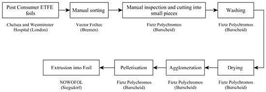
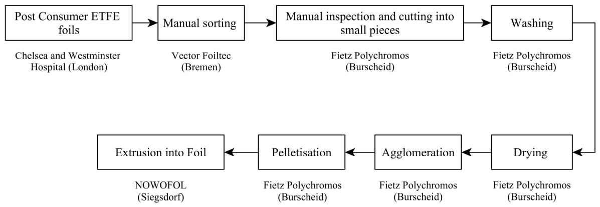
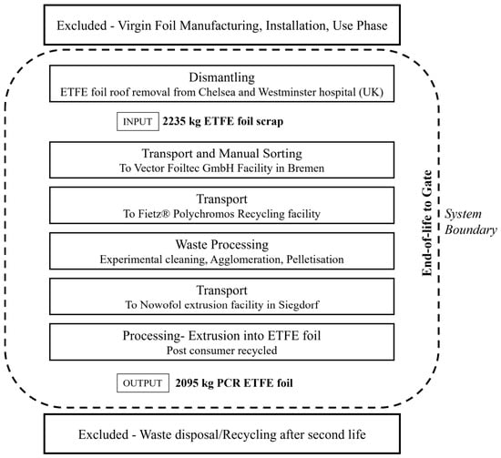
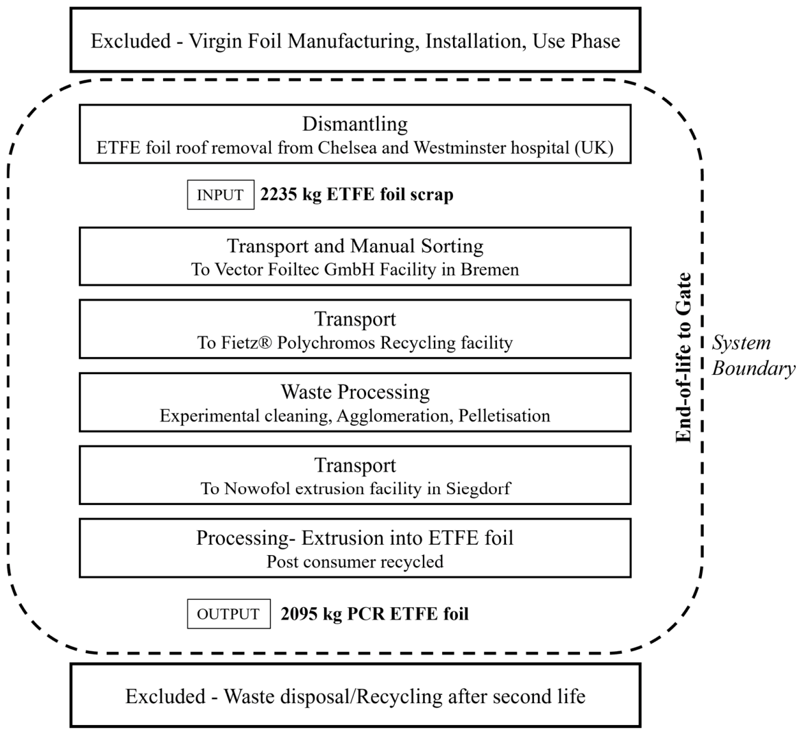
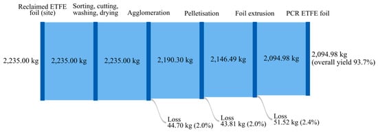
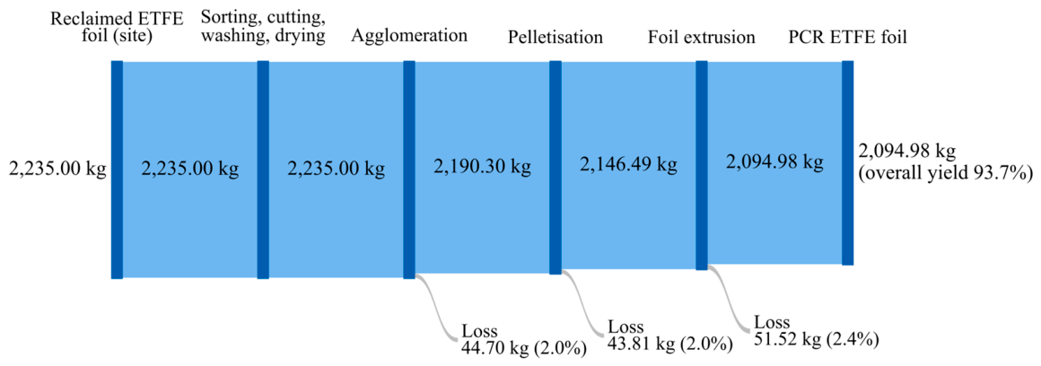
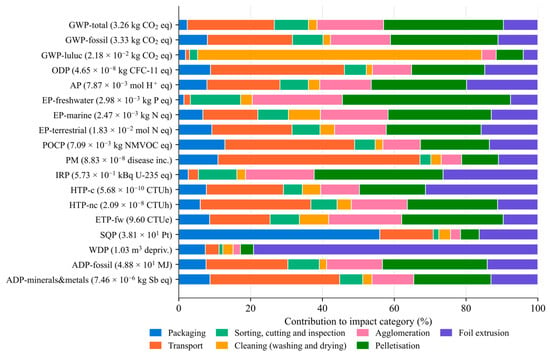
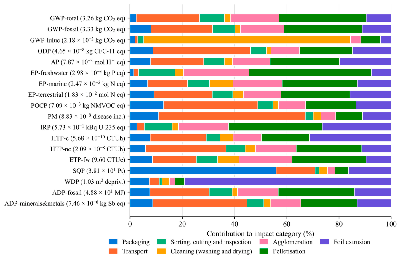
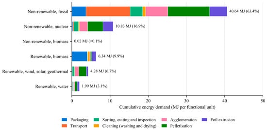
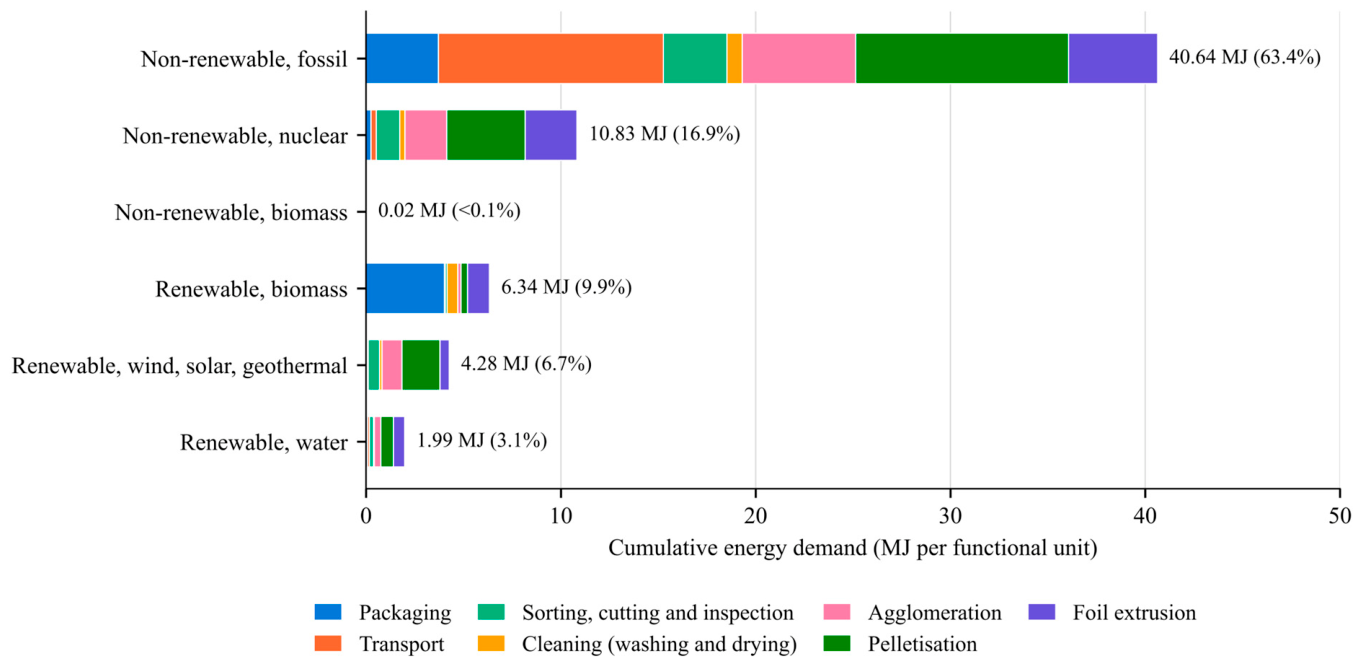
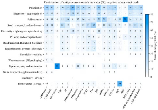
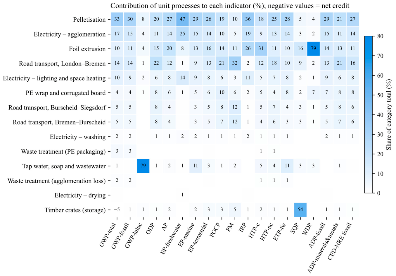
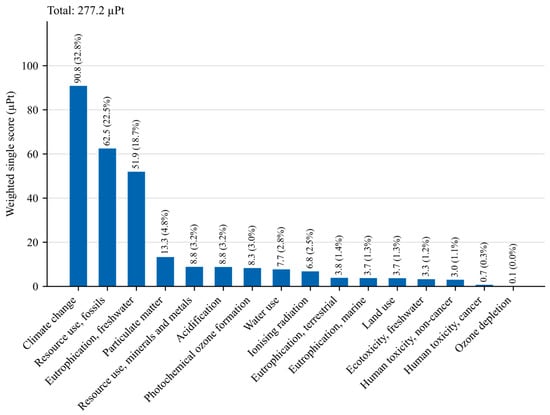
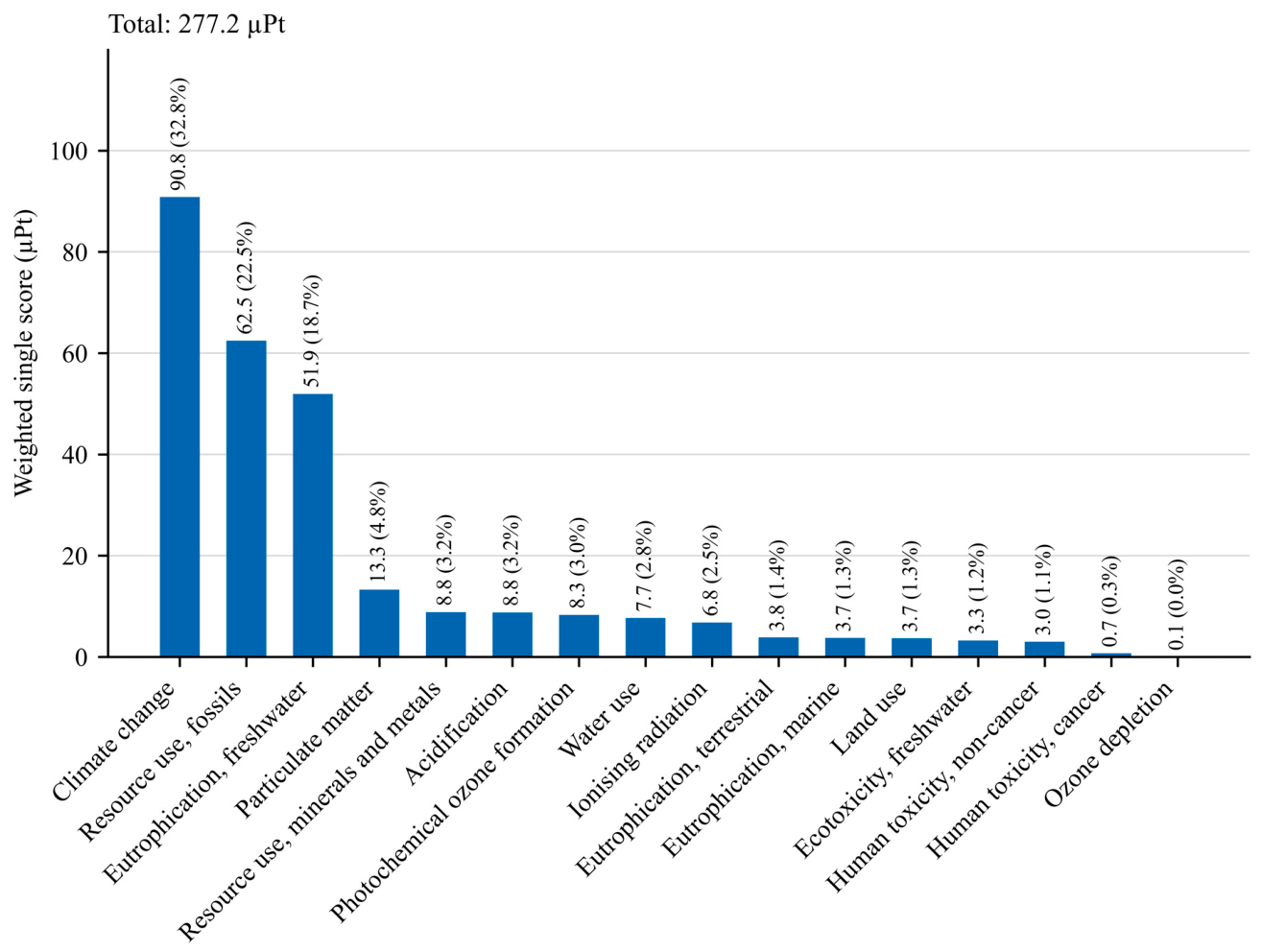
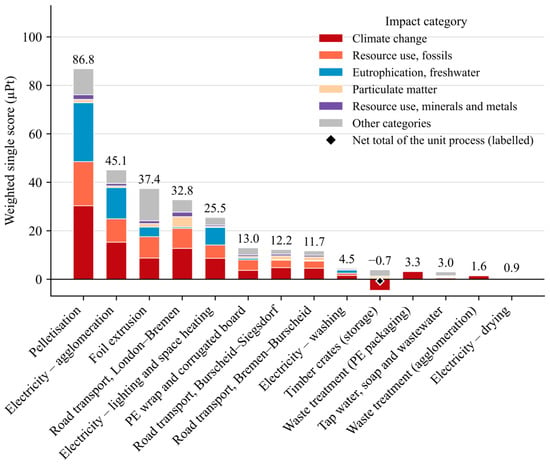
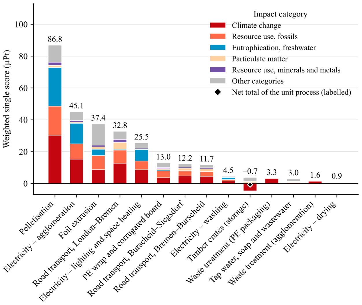
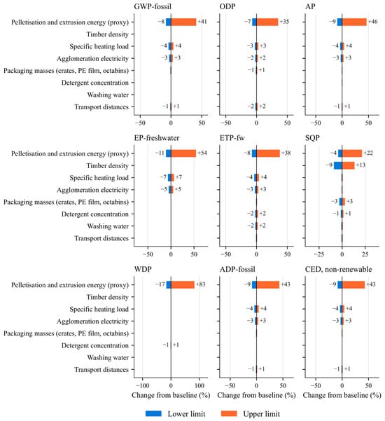
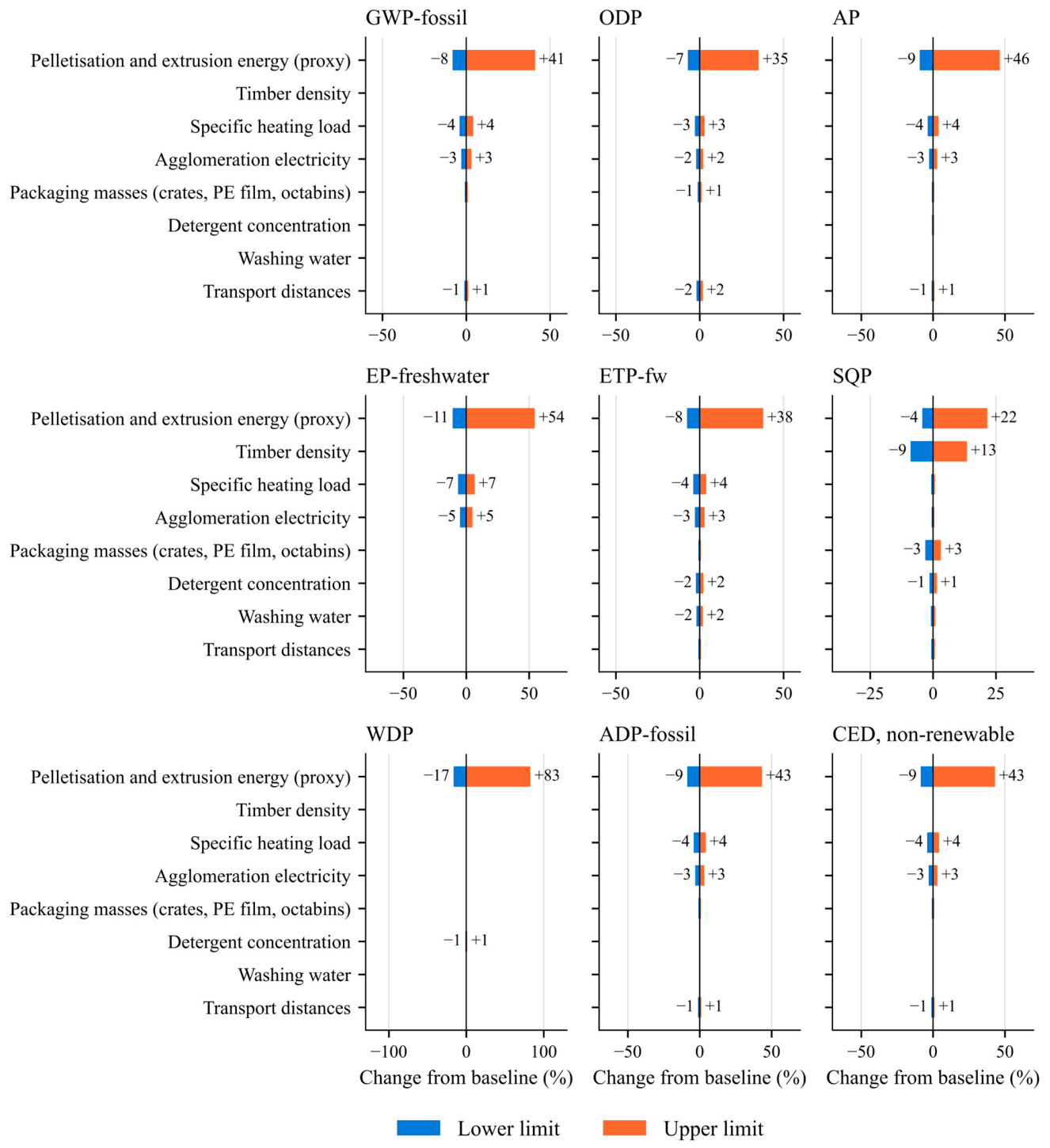
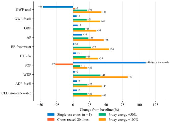
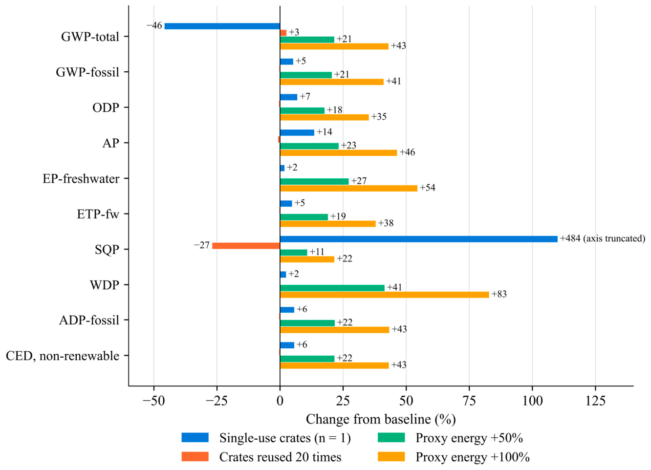
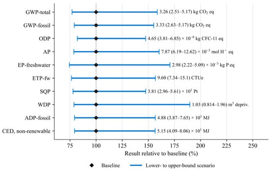
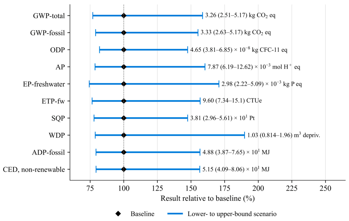

Disclaimer/Publisher’s Note: The statements, opinions and data contained in all publications are solely those of the individual author(s) and contributor(s) and not of MDPI and/or the editor(s). MDPI and/or the editor(s) disclaim responsibility for any injury to people or property resulting from any ideas, methods, instructions or products referred to in the content. |
© 2026 by the authors. Licensee MDPI, Basel, Switzerland. This article is an open access article distributed under the terms and conditions of the Creative Commons Attribution (CC BY) license.