


Abstract
Much of the existing Mediterranean building stock was constructed before the introduction of modern seismic and energy-performance standards and therefore requires sustainable rehabilitation addressing both structural vulnerability and poor energy efficiency. Moreover, the marked variability in seismic hazard and climatic conditions across the region calls for assessment methods capable of evaluating retrofit effectiveness under different environmental conditions. This study introduces a multi-site assessment framework for evaluating integrated seismic and energy retrofit solutions, including passive control systems—tuned mass damper, tuned mass damper inerter and base isolation—integrated with energy-oriented interventions, employed at roof or ground level, aimed at improving envelope performance or providing on-site renewable energy generation. The framework is applied to a representative three-story reinforced-concrete residential building with masonry infill walls and no thermal insulation, considering three Mediterranean sites with different seismic and climatic conditions. The structural response is simulated through a nonlinear finite element model employing lumped plasticity hinges for reinforced concrete members and infill walls. Dynamic building energy analyses are performed through simulations by means of the transfer function method, with hourly time steps and typical meteorological year. The structural and energy responses are synthesized through properly defined integrated performance indicators, which allow for comparative assessment of alternative retrofit strategies according to different design priorities. The results show that retrofit effectiveness is site-dependent. Base isolation provides the greatest structural improvement, whereas the performance of roof-level control systems varies with seismic hazard and spectral characteristics. From an energy perspective, cool roofs, green roofs and insulated ground-floor slabs modify heating and cooling demands by improving specific components of the building envelope but provide only moderate reductions in overall primary energy consumption. Conversely, photovoltaic roofs generate on-site renewable electricity and produce the best energy performance. The tuned mass damper inerter configuration combined with a photovoltaic roof achieves the most favorable integrated performance when equal importance is assigned to structural and energy objectives. The proposed framework supports the development of holistic, regionally adaptable strategies aimed at enhancing the safety, sustainability and efficiency of Mediterranean buildings.
1. Introduction
The sustainable rehabilitation of existing buildings is increasingly recognized as a strategic priority, driven by the combined pressures of urban resilience, resource efficiency, and seismic risk mitigation. As cities confront aging building stocks, rising environmental demands, and the need to ensure safety under multiple hazards, the upgrading of existing structures has evolved into a multidimensional challenge [1]. The Mediterranean region represents one of the few areas worldwide where significant seismic hazard coexists with rapidly increasing climate-related stresses. These countries are increasingly confronted with the challenge of rehabilitating a building stock largely constructed before the development of modern seismic and energy-efficiency standards.
A substantial portion of these buildings was designed primarily to withstand gravity loads, with limited consideration of horizontal seismic actions and with detailing that does not comply with current capacity-design principles. In particular, these buildings include unreinforced masonry infill walls, whose global and local response can be affected by their brittle failure mechanism [2]. The consequences of these deficiencies have been repeatedly demonstrated by recent earthquakes across the region, where even moderate events have caused severe structural damage, partial collapses, and prolonged service interruptions in residential and public buildings. In parallel, the Mediterranean building stock is predominantly energy-inefficient, characterized by inadequate thermal insulation, outdated heating and cooling systems, and envelope components poorly suited to increasingly frequent heatwaves and climatic extremes [3]. Given that the building sector is a major contributor to global greenhouse gas emissions, improving its performance is essential for meeting European decarbonization targets. This dual deficit in seismic safety and energy efficiency has therefore placed the integrated rehabilitation of existing buildings at the center of both technical research and policy agendas [4].
Among seismic retrofit solutions, passive control systems emerge as particularly promising for their reliability and possibility with respect to being integrated with other retrofits. Base isolation (BI) reduces seismic demand on the superstructure by introducing a flexible, energy-dissipating layer between the structure and its foundation [5]. Tuned mass dampers (TMDs) [6,7] have also gained significant attention due to their conceptual simplicity, adaptability, and suitability for roof-level installation—an advantageous feature for retrofit scenarios, as they can be incorporated externally or within existing roof volumes with minimal disruption to occupants. A conventional TMD consists of an auxiliary mass connected to the main structure through springs and dampers and tuned to a specific vibration mode to reduce structural response. However, achieving high effectiveness typically requires a relatively large mass ratio, which may be impractical in existing buildings due to the associated increase in gravitational loads and the potential need for additional strengthening. To address this limitation, non-conventional TMD configurations have been proposed, in which existing building masses—such as roof slabs or added rooftop structures—are converted into tuned masses through appropriate isolation and connection systems. More recently, the introduction of the inerter, a two-terminal device that generates a force proportional to the relative acceleration between its terminals, has expanded the possibilities for passive control. Through mechanical gearing or fluid mechanisms, inerters can achieve an apparent inertial mass several orders of magnitude larger than their physical mass. When combined with a TMD, the resulting tuned mass damper inerter (TMDI) [8,9,10,11] can deliver performance comparable to a nonconventional TMD while requiring significantly less added physical mass, making it particularly attractive for retrofit applications where additional weight is constrained. Beyond conventional discrete control devices, alternative resonance-based approaches exploiting metamaterial concepts have recently been proposed for vibration mitigation, including metamaterial-tailored structural members for vibration isolation [12,13], numerically and experimentally tested [14], and tunable quasi-zero-stiffness locally resonant systems [15]. These studies highlight the broader potential of tunable and multi-frequency resonant strategies.
Energy retrofit strategies in the Mediterranean region must account for marked climatic variability, ranging from hot–dry to colder and wetter conditions, which can substantially influence the effectiveness of individual retrofit measures [16,17]. Available solutions include passive envelope interventions, such as thermal insulation, high-performance windows, airtightness improvement, solar shading, and adaptive materials—as well as high-efficiency HVAC systems, heat-recovery ventilation, smart building controls, and on-site renewable energy generation [18]. Among these technologies, roof-level interventions are particularly relevant to the present study because they can improve the energy performance of the building envelope while also being integrated with the proposed structural-control systems. Cool roofs primarily limit summer overheating through high solar reflectance, although their effectiveness may be reduced by winter heating penalties. Green roofs provide additional insulation, shading and evapo-transpiration, while also contributing to urban heat-island mitigation; however, their performance remains strongly dependent on climate, construction characteristics and operating conditions [19]. Photovoltaic systems follow a different strategy by reducing net primary energy consumption through on-site renewable electricity generation and can also be combined with envelope insulation measures within broader energy-retrofit configurations [20]. These technologies represent promising options for the refurbishment of existing buildings in Mediterranean climates.
Although seismic and energy retrofit strategies have traditionally been developed as separate fields, their integration is increasingly recognized as necessary for the comprehensive rehabilitation of existing buildings. Addressing the two aspects independently may lead to incomplete or inefficient solutions: seismic retrofits that do not improve energy performance fail to meet climate and comfort requirements, while purely energy-oriented interventions may significantly upgrade the envelope and the systems of a building that remains structurally fragile. In such cases, investments in energy renovation may be partially or completely lost following a damaging earthquake, undermining both economic efficiency and public acceptance of large-scale renovation programs. This has motivated recent research on integrated retrofit strategies, where seismic and energy interventions are conceived and implemented together [21,22,23]. However, despite the growing interest in integrated retrofit solutions, limited research has addressed their performance across different Mediterranean contexts simultaneously accounting for both seismic hazard variability and climate-related energy demand. Moreover, comparative assessments of passive-control-based retrofit strategies within a unified seismic-energy framework remain scarce.
Motivated by these research gaps, this study proposes an innovative multi-site assessment framework for the evaluation of sustainable integrated seismic and energy retrofit solutions for existing Mediterranean buildings. The framework is conceived to simultaneously account for seismic hazard variability and climate-related energy demand within a unified methodology, enabling the assessment of retrofit effectiveness under different environmental conditions across the Mediterranean region. The proposed methodology combines structural and energy performance evaluated through nonlinear time-history analyses and dynamic building energy simulations within a unified evaluation procedure. The resulting performance indicators are combined to enable a comparative assessment of alternative retrofit strategies according to different structural and energy priorities. The framework thus considers structural resilience and energy efficiency as complementary dimensions of sustainable building rehabilitation.
To demonstrate its applicability, the framework is applied to a representative three-story reinforced-concrete (RC) residential building with masonry infill walls and no thermal insulation, reflecting a large portion of the Mediterranean building stock constructed before modern seismic and energy regulations. Four integrated retrofit solutions are investigated, combining passive seismic-control technologies, namely TMDs, TMDIs and BI, with energy-oriented interventions at roof or ground-floor level. The selected solutions represent case-specific configurations tailored to ensure functional compatibility between structural-control devices and associated energy interventions; however, they are not intended to exhaust the range of possible combinations, as alternative pairings could be defined and evaluated within the same framework proposed. The assessment is performed considering three Mediterranean sites characterized by different seismic hazards and climatic conditions. Through this multi-site application, the proposed framework enables the investigation of how geographical and environmental variability influences retrofit effectiveness and supports the identification of sustainable integrated retrofit solutions capable of simultaneously enhancing seismic resilience and energy performance.
2. Integrated Seismic and Energy Interventions: Conceptualization and Design Strategy
2.1. Conceptualization
The retrofit strategies developed in this study combine and integrate passive seismic-control technologies for structural refurbishment with energy-oriented interventions. The selected solutions are representative of different retrofit philosophies and intervention locations within the building system, allowing the framework to investigate their effectiveness under varying seismic and climatic conditions. The integrated strategies presented are organized into two principal categories, distinguished by the structural element through which the combined seismic and energy upgrade is achieved. The first category encompasses interventions based on TMD concepts, all of which are implemented at roof level and exploit the roof slab as the controller mass for passive control. The second category concerns the BI solution, where the intervention is instead applied at ground level and relies on the decoupling of the building from the foundation system. Despite their different locations within the structural system, all proposed strategies share a common design philosophy: the slab—whether positioned at the roof or at the ground floor—is reconfigured to deliver improved energy performance while being mechanically separated from the main structural frame through a flexible, high-damping interface composed of elastomeric isolators. This decoupling enables the slab to act simultaneously as an energy-efficient component and as a functional element of the seismic protection system.
The four retrofit interventions developed within this framework are presented in Table 1. For each solution, attention is given to both the structural configuration adopted to achieve the desired seismic response modification and the specific energy-efficiency measures integrated into the slab system. This dual perspective highlights how each intervention combines structural and thermal enhancements within a unified retrofit scheme. The selected pairings reflect physical compatibility between the seismic-control system and the corresponding energy intervention. Roof-based control strategies (TMD and TMDI) are naturally combined with roof-level energy measures, whereas base isolation is associated with interventions located at the ground-floor level. This approach allows each retrofit strategy to exploit the same building component for both seismic and energy purposes, maximizing functional integration and minimizing construction invasiveness.
Table 1.
Integrated seismic and energy interventions.
In intervention #I1, the existing roof is structurally disconnected from the substructure and transformed into a new energy-efficient roof system through the application of a cool-roof coating, which reduces solar absorptance and improves thermal performance. The separation between the roof and the supporting structure is achieved by introducing a dedicated disconnection layer, within which elastomeric seismic isolators are installed. This configuration enables the roof to oscillate relative to the substructure, effectively converting its original mass into the tuned mass of a non-conventional TMD system.
In this way, the intervention exploits the existing roof mass already present in the building, allowing it to serve simultaneously as a functional roof slab and as the seismic control element of the retrofit strategy. In intervention #I2, the existing roof is demolished and reconstructed to create a new energy-efficient roof system based on the green-roof technique. The rebuilt roof incorporates a mass that is similar, though not identical, to the original one, allowing it to function as an enhanced thermal component while simultaneously serving as the auxiliary mass of the seismic control system. The new roof slab is supported on a dedicated disconnection layer, within which elastomeric seismic isolators are installed. This configuration transforms the reconstructed roof into a large-mass TMD, characterized by a high mass-ratio between the roof mass and the substructure, thereby increasing the efficiency of energy transfer and supplemental damping. The isolators are positioned directly beneath the roof floor, enabling controlled relative motion and ensuring the proper activation of the tuned-mass mechanism. In intervention #I3, the existing building remains unaltered, and a new lightweight, energy-efficient roof system is constructed above the original roof. This added roof incorporates photovoltaic panels across its surface, contributing to a reduction in the building’s primary energy demand. A dedicated disconnection layer is introduced between the new roof and the existing structure, within which elastomeric seismic isolators are installed to allow controlled relative motion. From the roof level to the ground floor, an inerter device is positioned to enhance vibration control and system effectiveness. The combination of the lightweight isolated roof, the inerter, and the supporting substructure results in the formation of a TMDI system, providing an integrated solution for both seismic performance enhancement and energy upgrading. In intervention #I4, the retrofit focuses on the ground-floor slab, which is upgraded to a thermally enhanced, energy-efficient configuration. The slab is structurally disconnected from the foundation by introducing a dedicated separation layer at the base of the building. Within this layer, elastomeric seismic isolators are installed to accommodate seismic displacements and reduce the transmission of ground motion to the superstructure. Through this configuration, the intervention effectively implements a BI system, improving both the seismic performance and the thermal efficiency of the building without altering the overlying structural components. It should be noted that, for interventions #I1, #I2 and #I3, the auxiliary masses are determined by the physical characteristics of the corresponding energy-efficient roof configurations, resulting in different mass ratios for the control systems. Consequently, the comparison concerns the complete integrated retrofit solutions and should not be interpreted as an equal-mass comparison aimed at isolating the individual contribution of the TMD and TMDI control concepts, as may be done when comparing structural-control systems independently of their associated energy-retrofit configurations.
A synthesis of the four proposed interventions is presented in Table 1, while Figure 1 illustrates schematic representations of the interventions applied to a multi-degree-of-freedom (MDOF) frame-story model of the existing building. It is worth noting that the selected pairings reported in Table 1 are representative rather than exhaustive; however, they reflect the rationale assumed in terms of combining the interventions. Interventions #I1 and #I2 exploit the relatively large mass of the existing or reconstructed roof as the moving mass of a non-conventional TMD. In intervention #I3, the lightweight photovoltaic roof provides a considerably smaller physical mass, and the inerter is introduced to enhance its effective inertial contribution without increasing the mass added at roof level. For intervention #I4, both the thermal and seismic interventions are located at the ground-floor interface, preserving the dual use of the same building component. Other possible combinations of the structural and energy parts of the integrated interventions are mechanically feasible but are not investigated in the present study.
Figure 1.
Different types of integrated seismic and energy interventions.#I1: Non-conventional TMD+Cool roof, #I2: Large mass TMD+Green roof, #I3: TMDI+Photovoltaic roof, #I4: BI+Thermally enhanced ground floor.
2.2. Design Strategy
For all configurations examined, the design is carried out according to the procedure described in the following sections, where the seismic and energy design strategies are discussed independently.
2.2.1. Seismic Retrofit Strategy
The structural design of interventions #I1, #I2, and #I3 is based on the methodology summarized in [8], which introduces a generalized two-degree-of-freedom (2-DOF) model from the original N-DOF frame story structure equipped with a TMDI device connected at levels j and k. The design of the interventions is conducted adopting a planar model with reference to the weakest directional plane of the building. The model adopted is originally formulated for a TMDI device (adopted in intervention #I3), characterized by elastic stiffness kT, viscous damping cT, mass mT and inertance b, coupled with the primary structure. It remains fully applicable and extendable also to the TMD design (interventions #I1 and #I2), by setting the inertance term b = 0, in the further dissertation.
The generalized 2-DOF model reported in Figure 2 is obtained by projecting the N-DOF structural dynamics of the building into the first vibration uncontrolled mode. It is formally done by approximating the N-DOF structural displacement vector u(t) as u(t) = ϕuj(t), where ϕ represents the first modal shape, normalized for obtaining the j-floor element unitary, and uj(t) is the j-floor relative displacement. The primary structure parameters are obtained as mI = ϕTMϕ, cI = ϕTCϕ, kI = ϕTKϕ, and representing respectively primary structure mass, damping, stiffness, and natural frequency. The TMDI system in the generalized 2-DOF model is represented by mass mT, connected to the primary structure through the linear spring of stiffness kT, inertial term b(1−∆ϕ) and the dashpot of damping coefficient cT; connection to the ground with coefficient inertial term b∆ϕ; and finally, in regard to coefficient inertial parameter b∆ϕ(∆ϕ − 1), connecting the primary structure to the ground. The ∆ϕ parameter is considered as the modal shape difference between j and k floors ∆ϕ = (1 − ϕk), including for k the TMDI placement connected to the primary structure. In the reduced 2-DOF formulation, input ground acceleration is derived from N-DOF excitation according to , where τ represents the unit vector of size N. TMDI natural frequency is evaluated as In non-dimensional form, the TMDI design parameters are mass ratio μ, inertance ratio β, location parameter ∆ϕ, frequency ratio ν, and damping factor ξT, with the following formulations:
Figure 2.
Two-degree-of-freedom (2-DOF) equivalent model of the primary structure equipped with a TMDI device (taken from [8]).
The control system is designed following the procedure based on maximizing the energy-dissipation index, named EDI, defined as the ratio between the energy dissipated by the device and the total input energy, based on the primary structure natural frequency and damping ratio, ωI and ξI, respectively.
The analytical expression of the EDI index is:
where EDI and EDT represent the dissipated energy increment in the viscous component of the primary structure and of the control system, respectively. A comprehensive discussion of this formulation is available in [8].
For interventions #I1, #I2, and #I3, the control mass is assigned with the energy-efficient mass selected for the retrofit solution. The design stiffness and damping values are derived from the formulations shown below:
The non dimensional parameters reported in Equation (1) represent the design parameters for intervention #I3, with designed stiffness and damping evaluated from Equations (3) and (4).
For interventions #I1 and #I2, which realize the TMD system with natural frequency , the design procedure is equivalent to that described for the TMDI case, with the inerter term assumed null and the TMD placed at the roof level. As a result, the non-dimensional parameters in Equation (1) reduce to μ, ν and ξT, whereas the control system design stiffness and damping are evaluated with Equations (3) and (4) assuming b = 0.
The first-mode linear formulation is used herein as a preliminary design model for determining the TMD/TMDI parameters. The resulting devices are subsequently implemented and assessed within the complete nonlinear finite-element model of the building. Previous investigations comparing conventional linear-model-based TMDI designs with optimization procedures explicitly accounting for nonlinear hysteretic response of the primary structure showed that the former can retain appreciable vibration-control effectiveness, although nonlinear-response-based optimization may provide improved performance [24]. Accordingly, the reduced-order formulation adopted here provides an efficient initial tuning of the control system, while its performance in the presence of structural nonlinearity and record-to-record variability is evaluated through nonlinear time-history analyses. Nevertheless, the present record-to-record assessment does not constitute a formal detuning or parameter-sensitivity analysis, which would require systematic variations in the device frequency ratio, damping ratio and inertance ratio beyond the primary scopes of this study.
The #I4 seismic intervention is developed following the formulation proposed in [25], in which the isolated building is idealized as a single-degree-of-freedom system governed by relative displacement across the isolation interface. The isolation system is modeled by means of a bilinear hysteretic constitutive law, defined by initial stiffness K1, post-yield stiffness K2, and characteristic strength Q, as illustrated in Figure 3. The ratio between the post-yield and initial stiffness is expressed by parameter α = K2/K1.
Figure 3.
Fundamental parameters defining the hysteresis loop.
Starting from total mass of the building M, obtained considering also ground floor slab mass mb, the design procedure requires the preliminary definition of a set of target design parameters, namely isolation period TISO, effective damping ratio ξeff, post-yield stiffness ratio α, and design displacement demand D. These quantities are selected according to the desired isolation performance and constitute the input parameters of the design procedure.
The effective lateral stiffness of the isolation system is first determined from the target isolation period as:
Once the effective stiffness has been determined, the characteristic strength of the isolation system is obtained from the assumed effective damping ratio and design displacement as:
The post-yield and initial stiffnesses of the bilinear model are then calculated according to:
Finally, the equivalent viscous damping coefficient associated with the isolation system is evaluated as:
The resulting parameters completely define the equivalent bilinear model adopted for the numerical implementation of the isolation system.
The different constitutive representations adopted for the control devices in the four integrated interventions are consistent with the respective design formulations, well established in literature. The linear representation of the TMD/TMDI devices should therefore be regarded as an equivalent idealization within the adopted design framework; nonlinearities of their connecting elements, displacement limits and amplitude-dependent properties are not considered in the present study.
2.2.2. Energy Retrofit Strategy
The energy design of integrated interventions #I1, #I2 and #I3 follows the methodology proposed in [21], in which the energy-retrofit solution is selected according to the specific passive-control strategy adopted at roof level. In particular, cool roofs, green roofs, and photovoltaic roofs are integrated with the corresponding seismic-control systems in order to improve the thermal performance of the building envelope while simultaneously fulfilling the structural role required by the retrofit concept. More details about the design can be found in [21]. In all these interventions the technologies are extended to the entire available roof area: this assumption maximized the effect within the geometric constraints of the case-study building. The design of each intervention therefore preserves the dual functionality discussed in Section 2.1, where the retrofitted roof acts both as an energy-efficient envelope component and as part of the seismic-control system.
Intervention #I4 adopts a different design philosophy because the seismic retrofit is implemented through base isolation at ground level. Consequently, the energy intervention is applied to the ground-floor slab, where a thermal insulation layer is introduced to reduce heat transfer between the conditioned indoor spaces and the ground. For the design, a 12 cm expanded polystyrene insulation layer, characterized by a thermal conductivity of 0.034 W/(m·K), is placed between the structural slab and the subfloor. The choice constitutes a representative solution in agreement with the applicable thermal-performance requirements based on the Italian regulations [26].
While the adopted assumptions for designing the interventions enable a consistent comparison of the proposed integrated strategies, a broader sensitivity analysis would be required to assess the robustness of the ranking with respect to the energy-design variables.
2.3. Integrated Design Philosophy
Unlike conventional retrofit approaches, the seismic and energy components of the proposed interventions are not designed independently and subsequently combined. Instead, the energy-retrofit element itself becomes part of the seismic-control system. In roof-based interventions, the upgraded roof simultaneously acts as an energy-efficient envelope component and as the control mass of the TMD or TMDI device. Similarly, in the base-isolated configuration, the thermally enhanced ground-floor slab is integrated within the seismic-isolation system. This dual functionality represents the key concept underlying the proposed retrofit solutions and enables a more efficient use of construction resources while improving both seismic and energy performance.
3. Multi-Site Assessment Framework
A large part of the Mediterranean region is characterized by the coexistence of significant seismic hazard and increasing climate-related stresses, making existing buildings simultaneously vulnerable to earthquake-induced damage and poor thermal performance. These combined challenges require assessment methodologies capable of evaluating retrofit solutions from both structural and energy perspectives rather than considering the two aspects independently.
To address this need, a multi-site assessment framework considering both seismic and climate characterizations is proposed for evaluating different integrated seismic and energy retrofit solutions for Mediterranean buildings. The framework is conceived as a general methodology that combines seismic and energy assessments within a unified evaluation procedure while explicitly accounting for the geographical variability of seismic hazard and climatic conditions across the Mediterranean basin.
The proposed methodology is based on five sequential steps. First, a representative building archetype together with a portfolio of integrated retrofit solutions is defined. Second, representative Mediterranean sites are selected to capture different combinations of seismic hazard and climatic conditions. Third, the seismic hazard and climate characterization associated with each site is conducted, utilized as input into the structural and energy assessment procedures. Subsequently, the retrofit solutions are evaluated through dedicated structural and energy analyses. Finally, the obtained responses are synthesized through integrated performance indicators, allowing the comparative assessment of the alternative retrofit strategies and supporting the identification of the most suitable solution under different environmental conditions. The overall workflow of the proposed framework is illustrated in Figure 4, while the individual methodological steps are described in the following subsections.
Figure 4.
Multi-site assessment framework. #I1: Non-conventional TMD+Cool roof, #I2: Large mass TMD+Green roof, #I3: TMDI+Photovoltaic roof, #I4: BI+Thermally enhanced ground floor.
3.1. Building Archetype and Retrofit Solutions
Following the building typologies identified by the European Commission as priorities for integrated seismic and energy rehabilitation [4], the building archetype represents the existing Mediterranean reinforced-concrete residential stock constructed during the 1960s–1970s, characterized by gravity-load design, masonry infill walls and poor thermal performance. Four integrated retrofit strategies, described in Section 2, are considered within the framework. These combine passive seismic-control systems with compatible energy-oriented interventions, providing a representative portfolio for evaluating alternative sustainable rehabilitation solutions under different environmental conditions.
3.2. Multi-Site Selection
To investigate the influence of geographical variability on the effectiveness of integrated retrofit solutions, the framework adopts a multi-site approach based on three representative locations within the Mediterranean basin: Valencia (Spain), Catania (Italy) and Thessaloniki (Greece). These sites were selected to represent different combinations of climatic conditions and seismic hazard levels that characterize Mediterranean regions requiring integrated seismic and energy rehabilitation [4].
The selected locations encompass distinct Köppen climate classifications [27], reflecting different thermal demands and cooling requirements, together with different peak ground acceleration (PGA) levels and soil conditions [28,29], representative of the seismic variability across the Mediterranean region. This variability enables the framework to assess the robustness and possible transferability of integrated retrofit solutions under different environmental scenarios.
The geographical, climatic and seismic characteristics of the selected sites are summarized in Table 2.
Table 2.
Characteristics of the Mediterranean sites adopted in the multi-site assessment framework. 1 Soil type is reported according to the classification provided in [29]; 2 climate classification is based on the Köppen Map [27].
3.3. Seismic Hazard and Climate Characterization
The selected sites are characterized through seismic hazard and climatic conditions, which constitute the environmental input for the structural and energy assessments.
Concerning the seismic hazard, the reference seismic action is defined according to [29], considering a 10% probability of exceedance in 50 years, corresponding to a return period of 475 years herein associated with the Life Safety Limit State. Site-specific hazard parameters, including PGA and soil classification, are obtained from the European Facilities for Earthquake Hazard and Risk (EFEHR) platform [30]. The resulting hazard levels range from moderate seismicity in Valencia to high seismicity in Thessaloniki, providing a representative spectrum of seismic conditions across the Mediterranean basin. To represent the seismic input, seven real ground-motion records are selected for each site from the European Strong-Motion (ESM) database [31] through Rexel 2.1.10 software [32]. Record selection is performed to ensure compatibility with the target elastic response spectrum associated with each location. The selected records fall within magnitude and distance ranges representing the local seismic hazard. Although the Rexel selection window spans Mw = 0–6.5 and R = 0–100 km, the effective dataset includes only events with Mw ≥ 4. All selected records meet the adopted spectral-compatibility criteria, remaining within the bounds of 30% and 10% respectively over the period interval encompassing the three fundamental vibration modes of the structure.
All accelerograms are scaled using a uniform scale factor to match the spectral ordinate of the target spectrum at the fundamental period of the as-is building. The two horizontal components of each selected record are considered in separate analyses, applying the strongest component along the X-direction and the orthogonal component along the Y-direction. Figure 5 presents the selected spectrum-compatible records together with their mean spectra and the corresponding target spectra for the three sites considered.
Figure 5.
Set of seven natural spectrum-compatible acceleration response spectra with their mean value and target spectra with lower and upper bound, together with the first three natural periods of the AS-IS building. Left column, X-direction spectrum; right column, Y-direction spectrum. (a,b) Valencia, (c,d) Catania, (e,f) Thessaloniki.
Concerning the climatic conditions, the selected sites cover three distinct climate classes: BSh (Valencia), Csa (Catania) and Cfa (Thessaloniki), representative of different thermal regimes and cooling demands. This climatic variability enables the assessment of the effectiveness of the proposed energy-retrofit solutions under different environmental conditions.
3.4. Performance Evaluation Metrics and Assessment Criteria
For each retrofit configuration and each selected Mediterranean site, the structural response is assessed by means of nonlinear dynamic analyses, whereas the energy performance is evaluated through dynamic building energy simulations. The modeling approaches adopted for the structural and energy analyses are described in Section 5.1 and Section 5.2, respectively. The results obtained from these analyses are subsequently synthesized through a set of normalized performance indicators, enabling a consistent comparison of the proposed retrofit solutions under different seismic and climatic conditions. The final stage of the framework consists of the integrated evaluation of the proposed retrofit solutions through a set of structural and energy performance metrics. Two performance indicators are introduced, each one evaluated for the four integrated interventions and for each of the selected Mediterranean sites. In the following, indicator h = 1–4 corresponds to intervention I#h, as reported in Table 1, whereas indicator j = 1–3 corresponds to the selected site as reported in Table 2.
The structural performance indicator is based on the interstory drifts of the primary structure, as this response quantity is a key measure of seismic vulnerability. Let dn(h,j) be the drift vector for the h-th intervention in the j-th site, where component di(with i = 1–3) represents the peak drift at floor i under ground motion n. The drift-based structural index JS is defined as:
Index JS(h,j) expresses the mean norm of the drift vector over all ground motions for the h retrofitted configuration, normalized with respect to the corresponding value in the AS-IS condition at the j-site.
For the energy analysis, the overall energy balance of the building site is assessed through primary energy consumption (PEC), defined for the h-th intervention in the j-th site as:
where PECgas and PECel denote the primary energy consumption from gas and electricity, respectively (kWh hp); PEP is the primary energy production; Hnd and Cnd represent the net heating and cooling demand (kWh) respectively; RENPV is the renewable electric energy generated by the photovoltaic system (kWh); and PEel,f is the primary electric energy conversion factor. The remaining coefficients appearing in Equation (10) are constant parameters adopted as ηG = 0.92, COP = 2.5, PEel,f = 2.42, [21].
As an energy performance indicator, the ratio between PEC in the retrofit case normalized with respect to the same quantity evaluated in the AS-IS case (i.e., without intervention) is adopted. For the h-th intervention in the j-th site, energy index JE is therefore defined as:
Since both JS and JE are defined as ratios with respect to the corresponding AS-IS performance, a value equal to 1 indicates no change relative to the original building, a value lower than 1 indicates an improvement, and a value greater than 1 indicates a deterioration. Lower values correspond to better performance. Unlike JS, JE index as defined in Equation (11) may take negative values when renewable energy production exceeds consumption, which makes it inconsistent with JS when used in a combined optimization approach. Moreover, although both original indices are defined relative to the AS-IS configuration, their numerical ranges may differ considerably. To obtain dimensionless measures on a common scale for the subsequent weighted assessment, site-specific min–max normalized indices and are introduced as follows:
where JS,min(j) and JS,max(j) denote the minimum and maximum values of JS among the four retrofit alternatives for site j, and JE,min(j) and JE,max(j) are defined analogously for JE. For the structural index, the normalization is performed separately for each analysis direction. Accordingly, and range from 0 to 1, where 0 identifies the best-performing retrofit and 1 identifies the worst-performing retrofit within the set of alternatives considered for the same site. Unlike original indices JS and JE, the normalized indices do not provide a direct measure of improvement relative to the AS-IS configuration; they express the relative position of each intervention between the best and worst alternatives.
Once introduced the new normalization for JS*(h,j) and JE*(h,j), a bi-objective index is defined as the weighted sum of JS*(h,j) and JE*(h,j):
where w represents a weight coefficient varying in the range [0–1]. In this study a weight coefficient, w = 0.5, has been assumed considering equal weights for the structural and energy parts of the integrated interventions. The optimal integrated intervention is therefore selected by minimizing the index.
4. Case Study
The case-study building is a three-story RC frame structure constructed in the 1960s–1970s and originally designed for gravity loads only. The structural system consists of two-way moment-resisting frames in both the longitudinal (X) and transverse (Y) directions. Along the X-direction, four frame alignments (1, 2, 3, 4) are present, each with three spans of varying lengths. Along the Y-direction, three alignments (A, B, C) form two spans of equal length. Front views in X-Z and Y-Z planes are reported in Figure 6a,b, while Figure 6c illustrates the rectangular floor plan, which covers approximately 162.5 m2. Each story is 3 m high, with a total building height of 9 m.
Figure 6.
Case study building (a) front view (X-Z plane), (b) front view (X-Z plane), and (c) plan view. Numbers 1 to 4 indicate alignments along the X-direction, letters A to C indicate alignments along the Y-direction.
All columns have cross-sections of 40 × 35 cm. Perimeter beams and internal beams in the X-direction (projecting beams) measure 35 × 55 cm, whereas internal beams in the Y-direction (slab-depth beams) measure 55 × 20 cm. The floors consist of RC slabs with a 4 cm concrete topping over hollow clay blocks, resulting in a total slab depth of 20 cm. The exterior infill walls are constructed with brick masonry.
5. Modeling Framework and Analysis Procedures
A set of structural and energy models is developed to represent the building in its existing condition as well as after the implementation of four retrofit strategies. In total, five configurations are analyzed:
- the unretrofitted building (AS-IS);
- the building with intervention 1 (#I1);
- the building with intervention 2 (#I2);
- the building with intervention 3 (#I3);
- the building with intervention 4 (#I4).
The following subsections describe in detail the modeling approaches adopted for both the structural and energy analyses.
5.1. Structural Modeling
The structural analysis is carried out using three-dimensional finite element models (FEMs) developed in commercial software SAP2000 V.26 [33]. Concrete is modeled as class C12/15 with a unit weight of 25 kN/m3 and a Young’s modulus of E = 27 GPa. Gravitational loads consist of permanent and variable loads of 5.19 kN/m2 and 2 kN/m2, respectively, on each floor, and 5.39 kN/m2 and 0.5 kN/m2 at the roof. Further details regarding the constitutive laws, material parameters, and modeling procedures used to represent the structural elements can be found in [21]. All beams and column joints were modeled using end-length offsets, assigning a rigidity-zone factor of 0.5 to account for the finite stiffness of the beam–column joint regions. Nonlinearity is assigned to all primary components of the structural system. Beams and columns are modeled as linear-elastic members with flexural inelasticity concentrated at their ends, where plastic hinges of predefined length are introduced. These hinges are located within end-offset regions with a total length of 0.5, ensuring a consistent representation of joint-region deformability. Masonry infill walls were modeled through equivalent diagonal struts in both directions, capturing their predominant in-plane failure mechanism. Each strut follows a nonlinear force–displacement relationship, with plastic hinges governed by the Pivot hysteresis model positioned 0.45 m from one end to avoid coincident hinge formation. Strut geometry is defined according to typical European infill-wall dimensions and established modeling procedures, while the presence of openings is accounted for by applying a reduction factor to the effective strut width, evaluated according to [34] and based on the building elevations reported in [35]. In addition to their mechanical contribution, the self-weight of the infill panels is applied as a distributed line load of 15 kN/m along the perimeter beams, with local reductions introduced in correspondence with window openings following the approach in [35]. Figure 7 represents a sketch of the FEM model with the constitutive relationships of the structural members.
Figure 7.
Case study description through 3D geometry, section sizes and constitutive laws for structural and nonstructural elements.
For the retrofitted configurations, the building and the passive-control devices form a dynamically coupled system. Literature studies highlight the importance for coupled systems of retaining the degrees of freedom and interaction mechanisms that govern the response of the dynamically coupled subsystems, e.g., [36]. In this context, for interventions #I1, #I2, and #I3, total control mass mT, corresponding to the energy-efficient roof configuration associated with each intervention, is distributed among a set of auxiliary roof nodes according to their tributary areas. These auxiliary nodes are distinct from the structural nodes located at the tops of the columns and are constrained by a separate rigid diaphragm. The total distributed nodal masses sum to mT. The elastic and viscous properties of the TMD and TMDI systems are represented by Nc = 12 linear link elements in SAP2000, one for each column. Each link connects a structural node at the top of a column to the corresponding auxiliary roof node located along the same vertical line. The uncoupled horizontal shear degrees of freedom of each link are assigned equal stiffness and damping properties in the two principal directions. Since the links operate in parallel, the properties assigned to each link are kT,link = kT/Nc and cT,link = cT/Nc, where kT and cT are the total device properties obtained from Equations (3) and (4). For intervention #I3, the inerter is modeled as a separate isolated rigid frame element whose terminals are connected to the mass of control system mT and the ground, respectively. The prescribed inertance is reproduced through an equivalent rotational inertia I = bL2, where b is the inertance and L is the distance between the inerter terminals, following the procedure for modeling an ideal inerter element in finite element simulation programs furnished in [37]. For intervention #I4, ground floor slab mass mb is distributed among the ground-floor slab nodes according to their tributary areas. These nodes are constrained by a rigid diaphragm and are separated from the foundation nodes. Hysteretic isolator link elements are adopted in SAP2000 to model the seismic isolators: one link element is placed beneath each column, connecting the corresponding ground-floor node to a coincident foundation node. The horizontal response of each isolator is represented through uncoupled bilinear laws acting in the two principal directions. The properties assigned to each of the isolators are K1,link = K1/Nc, K2,link = K2/Nc, Q link = Q/Nc, and ceff,link = ceff/Nc. The bilinear representation is adopted because the effective stiffness and energy-dissipation capacity of the isolation system depend on its hysteretic force–displacement response, characterized by the initial stiffness, post-yield stiffness and characteristic strength according to the design procedure.
Nonlinear dynamic time-history analyses are carried out through direct integration, using initial conditions derived from the completed nonlinear static gravity analysis. A constant time step of 0.005 s is adopted, and numerical integration is performed using the Hilber–Hughes–Taylor α-method. Geometric nonlinearities are not considered. A 5% proportional viscous damping ratio is assigned to the primary structural system for its first two vibration modes, while the supplemental damping provided by the TMD/TMDI links and the isolation system is explicitly represented through their respective device properties.
Owing to the regular and plan-symmetric configuration of the building, two separate nonlinear analyses of the three-dimensional model are performed, applying the ground-motion component independently along the two principal horizontal directions: the strong X-direction and the weak Y-direction. This assumption is consistent with similar studies in the literature [38].
5.2. Energy Modeling
For the energy analysis, the building was modeled in the TRNSYS18 environment [39] using the TRNBUILD module. Within TRNSYS 18, the building was represented through the Type56 component, which simulates the thermal behavior of multi-zone buildings. The case-study building was divided into three thermal zones, corresponding to the ground, first, and second-floor apartments.
Each thermal zone was characterized by its opaque envelope components, glazing systems, occupancy schedules, heating and cooling system schedules and temperature setpoints, and air infiltration rates. Additional details regarding the building modeling approach are provided in [21].
A simulation timestep of 1 h was adopted, which was also used for the calculation of the building transfer functions. Domestic hot water production and lighting were excluded from the energy balance, as these loads are assumed to be independent of climatic conditions and therefore remain unchanged across the scenarios considered. Furthermore, the building models did not include mechanical ventilation.
The heating and cooling schedules were defined as follows. During the heating season, the indoor air temperature setpoint was fixed at 21 °C between 6:00 and 22:00 (16 h per day), in accordance with current Italian regulations, while a nighttime setback temperature of 16 °C was applied during the remaining hours. During the cooling season, a constant indoor temperature setpoint of 26 °C was maintained throughout the day, with no nighttime setback.
6. Results
The proposed assessment framework is applied to the case-study building considering the four integrated retrofit strategies and the three representative Mediterranean sites introduced in the previous sections. The results are presented following the workflow of the proposed methodology. First, the dynamic characteristics of the reference building and of the retrofitted configurations are discussed to define the design parameters of the seismic-control systems. Subsequently, the structural and energy performances of the proposed retrofit solutions are evaluated through nonlinear dynamic analyses and building energy simulations. Finally, the structural and energy indicators are combined within the integrated assessment framework to identify the most suitable retrofit strategy under different environmental conditions.
6.1. Modal Analysis
A preliminary modal analysis of the AS-IS structure is performed to characterize its dynamic properties and to derive the parameters required for designing the structural components of the integrated interventions. Two reference models are considered. Model #M0 corresponds to the complete AS-IS structure and is used to derive the design parameters for interventions #I1, #I3, and #I4. Model #M1, instead, represents the AS-IS structure without the roof and is used to determine the parameters relevant to intervention #I2.
Table 3 reports the first three vibration modes of the two reference models (#M0 and #M1) together with the retrofitted configurations, including the corresponding natural periods and modal participating mass ratios in the X- and Y-directions. Assembling the results from both analyses, for the AS-IS structure (model #M0), the first mode is predominantly translational in the Y-direction, with a period of 0.30 s and a participating mass ratio of 91%. The first eigenvector, normalized to unity at the roof level, is the first modal shape, ϕ = [0.43 0.81 1]T. For the AS-IS structure without the roof (model #M1), the first mode also corresponds to a translational motion in the Y-direction, with a shorter period of 0.26 s and a participating mass ratio of 92%. The corresponding normalized eigenvector is the first modal shape, ϕ = [0.50 0.80 1]T.
Table 3.
Periods and participating mass ratios of the first three modes for models #M0 and #M1, and models with interventions #I1, # I2, #I3, and #I4.
Based on the modal results of models #M0 and #M1, the dynamic parameters of the reduced-order model representing the primary structure—used for designing the interventions—are summarized in Table 4.
Table 4.
Reduced-order model parameters of reference models #M0 and #M1.
The modal properties of the retrofitted configurations, whose design details are reported in Section 6.2, are also reported in Table 3. The results of modal analysis confirm the expected dynamic effects of the proposed interventions: the TMD- and TMDI-based solutions moderately increase the fundamental period of the structure, whereas the base-isolated configuration exhibits the substantial period elongation typical of seismic isolation systems.
6.2. Interventions Design
The seismic-control systems are designed considering the dynamic properties of the reference structure in its weakest direction (Y-direction). The modal properties reported in Table 4 are therefore adopted as the reference parameters for the design of the integrated retrofit interventions, whereas the effectiveness of the resulting solutions is subsequently verified in both principal structural directions. To design the structural component of the integrated TMD-based interventions, the mass of the new energy-efficient roof was first estimated for each solution. The roof masses adopted for the integrated interventions are taken from a previous study presented in [21]: values of mT = 92, 80 and 7 are adopted for interventions #I1, #I2 and #I3, respectively. Using these values together with the equivalent modal mass of the reference structure reported in Table 4, mass ratio μ for each intervention was computed through Equation (1). For intervention #I3, inertance ratio β = 0.4 was assumed. The TMDI terminals connect the roof to the ground, i.e., spanning three floors. Such choice is considered reasonable for the specific three-story case-study building and is in accordance with previous studies [8,40] indicating that increasing the number of stories spanned by the device can improve its capacity to control higher vibration modes. It should be noted that, for higher-story buildings, the connection of the second terminal to the ground could be practically unfeasible and interstory or intermediate-floor configurations would be preferable. Based on the optimal design procedure, the nondimensional optimal design parameters are summarized in Table 5 for the first three interventions.
Table 5.
Dimensionless parameters for interventions #I1, #I2, and #I3.
In the #I4 strategy, building total mass is established from model M0 mass adding ground floor slab mb, resulting in M = 803 . Because of the relatively high lateral stiffness of the infilled structure, a target isolation period of TISO = 1.5 s is adopted to achieve a significant spectral shift and consequently reduce the seismic demand transmitted to the superstructure. A damping ratio of ξeff = 0.15 is assumed, whereas a preliminary reference displacement under the design ground motions is assumed at D = 0.125 m. Those parameters are reported in Table 6.
Table 6.
Parameters for intervention #I4.
For interventions #I1, #I2 and #I3, the dimensional parameters obtained through the optimal design procedure are summarized in Table 7. For intervention #I4, the designed total effective lateral stiffness is Keff = 14,071 kN/m, with isolator properties defined by bilinear behavior characterized by elastic stiffness K1, post-yield stiffness K2, characteristic strength Q and effective damping coefficient ceff reported in Table 7.
Table 7.
Seismic design parameters for retrofit interventions #I1, #I2, #I3 and #I4.
The design of the energy efficiency improvement intervention concerning the insulation of the ground floor (#I4) slab was carried out using traditional construction techniques. Specifically, a 12 cm layer of expanded polystyrene insulation was introduced between the load-distributing screed and the structural slab element. The energy performance assessment was conducted according to the standards already described in the previously cited literature, namely by means of hourly dynamic simulation using TRNSYS 18 software and transfer function methods.
This intervention reduces the thermal transmittance of the ground floor slab in contact with the ground and, consequently, is expected to contribute to a reduction in the net heating and cooling energy demand for the ground floor, as well as for the building as a whole. Naturally, the improvement in energy efficiency achieved by insulating a floor is generally lower, in terms of reducing the specific heating and cooling energy demand, than that obtained by insulating an equivalent area of roof, ceiling, or external wall.
6.3. Dynamic Time History Analysis
The seismic performance of the proposed retrofit strategies is evaluated through nonlinear dynamic time-history analyses carried out for the seven spectrum-compatible ground motions selected for each Mediterranean site. The key response quantities evaluated along the building height include relative displacements, absolute accelerations, interstory drifts, and shear forces.
Figure 8, Figure 9 and Figure 10 report the mean peak structural responses obtained from the seven records in terms of relative displacements, interstory drifts, absolute accelerations and shear forces along the building height, for the three sites considered in Valencia, Catania and Thessaloniki respectively. For interventions #I1, #I2 and #I3 the upper node corresponds to the TMD/TMDI mass, whereas for intervention #I4 the bottom node represents the base-isolation level. The retrofit systems are designed using the dynamic properties of the building in the weakest structural direction (Y-direction); nevertheless, their effectiveness is evaluated in both principal directions in order to assess the robustness of the proposed solutions. Since the three selected sites are characterized by different combinations of seismic intensity and local soil conditions, which strongly influence the structural response, the effectiveness of the retrofit interventions is discussed separately for Valencia, Catania and Thessaloniki.
Figure 8.
Mean values of peak responses evaluated for the set of seven accelerograms along floors in Valencia. Left column, responses with respect to the X-direction; right column, responses with respect to the Y-direction. (a,b) relative displacement, (c,d) interstory drift, (e,f) absolute acceleration, (g,h) shear force.
Figure 9.
Mean values of peak responses evaluated for the set of seven accelerograms along floors in Catania. Left column, responses with respect to the X-direction; right column, responses with respect to the Y-direction. (a,b) relative displacement, (c,d) interstory drift, (e,f) absolute acceleration, (g,h) shear force.
Figure 10.
Mean values of peak responses evaluated for the set of seven accelerograms along floors in Thessaloniki. Left column, responses with respect to the X-direction; right column, responses with respect to the Y-direction. (a,b) relative displacement, (c,d) interstory drift, (e,f) absolute acceleration, (g,h) shear force.
The structural response obtained for Valencia is shown in Figure 8. Although this site is characterized by a relatively low PGA, the presence of D-type soil significantly modifies the seismic input through amplification of the low-frequency components of ground motion [41]. As a consequence, the spectral peak shifts towards longer periods, increasing the likelihood of resonance for control systems such as TMDs and TMDIs. This behavior is reflected in the response of interventions #I1, #I2 and, to a lesser extent, #I3. The TMD-based solutions provide moderate reductions in terms of displacements, drifts, accelerations and shear forces, even if their effectiveness is response- and direction-dependent, with #I3 generally exhibiting the best performance among the roof-level control systems. However, a local increase in the acceleration response is observed in the X-direction for intervention #I3, which can be attributed to the interaction between the modified structural period and the amplified spectral content of the site. Conversely, intervention #I4 exhibits the typical response of a base-isolated structure. While large displacements develop at the isolation level, the superstructure undergoes an almost rigid-body motion, resulting in a substantial reduction in interstory drifts and shear forces. This confirms the effectiveness of base isolation under soil conditions characterized by strong low-frequency amplification.
Figure 9 presents the structural response obtained for the Catania site. Compared with Valencia, this location combines an intermediate seismic hazard with medium-stiff soil conditions (B-type). Under these conditions, all interventions overall reduce the seismic response with respect to the AS-IS configuration. Interventions #I1 and #I2 exhibit very similar response patterns, consistently with their comparable TMD properties. Intervention #I3 provides the best performance among the roof-based systems. This result reflects the combined effects of its mass, inertance and tuning parameters but should not be attributed exclusively to the inerter contribution, since the three integrated interventions are characterized by different auxiliary masses. Intervention #I4 provides the largest reduction in interstory drifts, as expected for a base-isolated structure. Although large displacements occur at the isolation interface, the seismic demand transmitted to the superstructure is significantly reduced, producing nearly uniform displacement profiles and very small relative deformations throughout the building. Overall, the Catania results demonstrate that all proposed retrofit solutions are effective under medium seismic hazard conditions, with the TMDI and BI systems providing the highest structural performance.
The results obtained for Thessaloniki are presented in Figure 10. This site is characterized by the highest seismic hazard among the three locations and by stiff (A-type) soil conditions. In this case, the seismic input contains a larger amount of high-frequency content, leading to a more significant contribution of the higher vibration modes. Under these conditions, the effectiveness of the roof-level vibration control systems decreases compared with the previous sites. The higher modal contribution produces less uniform response distributions along the building height and local acceleration peaks, particularly in the X-direction. This behavior is exacerbated for the TMD and TMDI solutions, whose increased fundamental periods move the controlled structure towards regions of higher spectral acceleration. Despite this more demanding seismic environment, intervention #I3 remains the most effective among the roof-based control strategies, consistently outperforming interventions #I1 and #I2. Intervention #I4 again exhibits the characteristic behavior of a base-isolated structure, concentrating the seismic displacement at the isolation level while maintaining very small drift demands in the superstructure. Overall, the Thessaloniki results highlight that the increasing seismic intensity together with the high-frequency content can lead in the case study building examined to a reduction in the effectiveness of the roof-level vibration control systems, whereas base isolation maintains stable performance owing to its ability to decouple the superstructure from ground motion.
It should be remarked that for intervention #I4, the largest mean peak isolation displacements obtained from the adopted ground motions are approximately 0.11 m for Valencia, 0.12 m for Catania, and 0.15 m for Thessaloniki. These results indicate that the preliminary reference displacement D adopted to calibrate the equivalent bilinear model of the isolators is consistent with the displacement demands obtained from the nonlinear analyses.
6.4. Energy Analysis
The energy performance of the proposed retrofit strategies is evaluated through annual heating demand Hnd, cooling demand Cnd and corresponding primary energy consumption PEC, whose values are summarized in Table 8. The results highlight the different contribution of each integrated intervention to building energy balance under the climatic conditions of the three Mediterranean locations.
Table 8.
Energetic output for the AS-IS building and the integrated interventions.
The roof-based passive solutions (#I1 and #I2) primarily affect the thermal loads of the building envelope. Both interventions significantly reduce annual cooling demand by limiting solar heat gains through the roof. This effect is particularly evident in the warmer climates of Valencia and Catania, where cooling requirements are more pronounced.
However, the reduction in solar gains is accompanied by an increase in heating demand during winter, since the roof admits less beneficial solar radiation. As a result, the overall reduction in primary energy consumption remains relatively limited. Among the two passive roof solutions, the green roof (#I2) generally provides larger reductions in cooling demand than the cool roof (#I1), although the associated increase in heating demand partially offsets this benefit, particularly in climates characterized by significant winter heating requirements. Intervention #I4, based on the thermal insulation of the ground-floor slab, exhibits a different behavior. As expected, the additional insulation considerably reduces the annual heating demand by limiting heat loss towards the ground. This improvement is accompanied by a moderate increase in cooling demand, since the thermal interaction with the ground is reduced during summer. Consequently, the overall reduction in primary energy consumption remains modest, suggesting that floor insulation alone cannot provide a comprehensive improvement of the energy performance of the building. A substantially different behavior is observed for intervention #I3, where the photovoltaic roof does not significantly modify building thermal demands, which remain essentially unchanged with respect to the AS-IS configuration. Nevertheless, the electricity generated by the photovoltaic system exceeds the annual energy demand for heating and cooling in all three locations, leading to negative values in terms of primary energy consumption. Consequently, intervention #I3 introduces an on-site renewable-energy contribution that, in primary-energy terms, exceeds the consumption associated with the heating and cooling uses considered in the present model. The intervention therefore produces a negative net primary-energy balance within the adopted system boundaries and provides the best energy performance among the investigated retrofit strategies, transforming the building from a net energy consumer to a net energy producer.
The influence of climatic conditions can also be observed from a comparison among the three sites. Valencia and Catania, characterized by higher cooling requirements, benefit more from roof-based passive solutions, whereas Thessaloniki remains predominantly heating dominated despite the reduction in cooling demand achieved by the roof interventions. Overall, the analyses demonstrate that, with the exception of the photovoltaic solution, the energy measures integrated into the proposed seismic retrofit strategies provide only moderate improvements in overall building energy performance. These results suggest that the proposed integrated interventions should not be interpreted as complete energy retrofit solutions. They represent energy-compatible seismic retrofit strategies that successfully combine structural upgrading with localized improvements in building thermal performance. However, a comprehensive energy rehabilitation would require additional interventions involving the remaining building envelope components and the Heating, Ventilation, and Air Conditioning (HVAC) systems, which regulate indoor temperature, air exchange, and overall thermal comfort.
6.5. Integrated Performance Assessment
Figure 11 summarizes the decision-making capability of the proposed assessment framework. The integrated performance of the retrofit strategies is evaluated through normalized performance index , obtained by combining the structural and energy indicators according to Equation (13). The corresponding structural and energy performance indices, evaluated from structural dynamic analyses and energy simulations, are reported in Table 9 and Table 10 for the X- and Y-directions, respectively. Weighting coefficient w varies between 0 and 1, allowing the relative importance assigned to structural and energy performance to be modified. In particular, w = 0 corresponds to a purely energy-oriented assessment, w = 1 represents an exclusively structural assessment, whereas w = 0.5 gives equal importance to the two objectives.
Figure 11.
Performance indicators for the retrofit strategies proposed. Left column, responses with respect to the X-direction; right column, responses with respect to the Y-direction, in which the colored marked points highlight at w = 0.5. (a,b) Valencia, (c,d) Catania, (e,f) Thessaloniki.
Table 9.
Performance indicators evaluated for the four integrated interventions evaluated in the X-direction ( evaluated for assumed weight coefficient w = 0.5).
Table 10.
Performance indicators evaluated for the four integrated interventions evaluated in the Y-direction ( evaluated for assumed weight coefficient w = 0.5).
In Valencia, when only the energy performance is considered (w = 0), intervention #I3 consistently provides the lowest value of the integrated index in both structural directions, owing to the photovoltaic roof that enables the building to operate as a net-energy producer. Conversely, when the optimization is driven exclusively by structural performance (w = 1), intervention #I4 becomes the preferred solution because of the superior effectiveness of the base-isolation system in reducing seismic demand. When equal importance is assigned to the structural and energy objectives (w = 0.5), intervention #I3 still represents the most effective compromise between the two performance domains, whereas #I4 remains competitive because of its outstanding structural performance despite its limited energy improvement. A similar trend is observed in Catania, Figure 11c,d: the energy-oriented assessment again identifies intervention #I3 as the optimal solution, while the structural assessment clearly favors #I4 in both directions. Compared with Valencia, the structural performance of the TMD-based solutions (#I1 and #I2) becomes more competitive, reflecting the favorable interaction between the control systems and the local seismic conditions. Under equal weighting (w = 0.5), intervention #I3 maintains the lowest integrated performance index, confirming the effectiveness of combining TMDI technology with photovoltaic energy production. The results obtained for Thessaloniki exhibit the same general behavior. Intervention #I3 remains the preferred solution when only energy performance is considered, whereas #I4 provides the lowest integrated index when structural performance becomes the governing objective. Compared with the other sites, the structural contribution of #I3 is less pronounced because of the higher seismic demand, while intervention #I2 becomes more competitive than #I1 as the weighting factor approaches w = 1.
Overall, Figure 11 highlights a consistent decision-making pattern across the three Mediterranean sites. Intervention #I3 systematically dominates the energy-oriented optimization because of its excellent energy performance, whereas intervention #I4 becomes the optimal solution whenever structural performance is prioritized. The relative ranking of interventions #I1 and #I2 is instead site-dependent, reflecting the influence of local seismic hazard and climatic conditions on the effectiveness of the retrofit solutions. These results demonstrate that the proposed framework is capable of identifying the most appropriate integrated retrofit strategy according to different design priorities while explicitly accounting for geographical variability across the Mediterranean region.
7. Conclusions
This study proposed a multi-site assessment framework for the evaluation of integrated seismic and energy retrofit strategies for existing Mediterranean reinforced-concrete buildings. The framework combined nonlinear seismic analyses and dynamic building energy simulations within a unified methodology, allowing alternative retrofit solutions to be compared under different seismic and climatic conditions. Unlike conventional approaches focused on a single location or a single performance objective, the proposed framework explicitly accounted for the influence of geographical variability, supporting sustainability-oriented decision making for the rehabilitation of the Mediterranean building stock. The framework was applied to a representative residential building through four integrated retrofit strategies combining passive seismic-control technologies with compatible energy-oriented interventions. The analyses highlighted that the effectiveness of the proposed strategies is influenced by local seismic and climatic conditions. Among the investigated sites, Catania represents the most favorable scenario, where all retrofit strategies provide significant structural improvements. Conversely, the higher seismic demand in Thessaloniki and the strong low-frequency soil amplification characterizing Valencia may reduce the effectiveness of roof-level vibration control systems. Under these more demanding conditions, the BI solution maintains the highest structural performance owing to its ability to decouple the superstructure from the ground motion and substantially reduce interstory drifts and seismic forces. Despite this, the feasibility of BI may always be constrained in dense urban environments, where adequate separation from adjacent buildings is not always available. Among the investigated roof-level configurations, intervention #I3 provided the most favorable structural performance. This result reflects the combined influence of its physical mass, inertance, damping and tuning parameters. The roof-to-ground-floor inerter configuration is adopted as a conceptual arrangement to illustrate the dynamic potential of the system; in practical applications, alternative layouts may be required depending on architectural and construction constraints.
From the energy perspective, the analyses showed that the proposed roof- and floor-based interventions produce different levels of improvement. The photovoltaic roof integrated with the TMDI system provides the largest reduction in primary energy consumption and enables the building to operate as a net-energy producer. By contrast, the cool roof, green roof and insulated ground-floor slab produce only moderate reductions in the overall energy demand. These results indicate that, although the proposed energy measures are fully compatible with the integrated retrofit philosophy and can be efficiently combined with passive seismic-control systems, they should not be regarded as complete energy retrofit solutions. Rather, they represent compatible interventions that can be complemented by additional envelope improvements and HVAC upgrading to achieve a comprehensive energy rehabilitation of the building.
Beyond the specific case study, the proposed framework provides a transferable methodology for comparing integrated retrofit strategies under different environmental and design conditions. Its application allows designers to quantify the influence of local seismic hazard and climatic characteristics on retrofit effectiveness and to identify the most appropriate intervention according to different structural and energy priorities. Future developments will extend the framework to additional building typologies and future climate scenarios, assess the sensitivity of the results to structural-control and energy-design parameters and pursue their simultaneous multi-objective optimization. The framework should also incorporate broader sustainability indicators, including construction feasibility, economic performance, embodied impacts and environmental life-cycle criteria, to provide a more comprehensive and robust assessment of alternative retrofit strategies.
Author Contributions
Conceptualization, M.B. and F.B.; methodology, M.B.; software, M.B., C.S. and F.B.; validation, M.B., C.S. and F.B.; formal analysis, C.S. and F.B.; investigation, C.S.; resources, M.B. and F.B.; data curation, C.S.; writing—original draft preparation, M.B. and C.S.; writing—review and editing, M.B., C.S. and F.B.; visualization, M.B., C.S. and F.B.; supervision, M.B.; project administration, M.B.; funding acquisition, M.B. All authors have read and agreed to the published version of the manuscript.
Funding
The research was funded by Universitas Mercatorum, Rome, Italy, under grant number 24-FIN/RIC (financial framework 2024).
Institutional Review Board Statement
Not applicable.
Informed Consent Statement
Not applicable.
Data Availability Statement
Data are available from the corresponding author upon request.
Conflicts of Interest
The authors declare no conflicts of interest.
References
- Passoni, C.; Caruso, M.; Felicioni, L.; Negro, P. The evolution of sustainable renovation of existing buildings: From integrated seismic and environmental retrofitting strategies to a life cycle thinking approach. Bull. Earthq. Eng. 2024, 22, 6327–6357. [Google Scholar] [CrossRef] [Scilit]
- Buonocunto, V.; Parisi, F.; Serino, G.; D’Ayala, D. Seismic vulnerability analysis of historic masonry buildings with multi-mode failure modelling. In Proceedings of the 18th World Conference on Earthquake Engineering (18WCEE), Milan, Italy, 30 June–5 July 2024. [Google Scholar]
- Bohne, R.A.; Huang, L.; Løhne, J. A global overview of residential building energy consumption in eight climate zones. Int. J. Sustain. Build. Technol. Urban Dev. 2016, 7, 38–51. [Google Scholar] [CrossRef] [Scilit]
- Romano, E.; Negro, P.; Santarsiero, G.; Masi, A.; Butenweg, C. Identification of European Buildings Most Needing Seismic and Energy Retrofit with a Focus on the Italian Context; Joint Research Centre, European Commission: Luxembourg, 2023. [Google Scholar]
- Kelly, J.M. Aseismic base isolation: Review and bibliography. Soil Dyn. Earthq. Eng. 1986, 5, 202–216. [Google Scholar] [CrossRef] [Scilit]
- Reggio, A.; De Angelis, M. Optimal energy-based seismic design of non-conventional tuned mass damper (TMD) implemented via inter-story isolation. Earthq. Eng. Struct. Dyn. 2015, 44, 1623–1642. [Google Scholar] [CrossRef] [Scilit]
- De Angelis, M.; Perno, S.; Reggio, A. Dynamic response and optimal design of structures with large mass ratio TMD. Earthq. Eng. Struct. Dyn. 2012, 41, 41–60. [Google Scholar] [CrossRef] [Scilit]
- Pietrosanti, D.; De Angelis, M.; Basili, M. A generalized 2-DOF model for optimal design of MDOF structures controlled by tuned mass damper inerter (TMDI). Int. J. Mech. Sci. 2020, 185, 105849. [Google Scholar] [CrossRef] [Scilit]
- Marian, L.; Giaralis, A. Optimal design of a novel tuned mass-damper-inerter (TMDI) passive vibration control configuration for stochastically support-excited structural systems. Probabilistic Eng. Mech. 2014, 38, 156–164. [Google Scholar] [CrossRef] [Scilit]
- Giaralis, A.; Taflanidis, A.A. Optimal tuned mass-damper-inerter (TMDI) design for seismically excited MDOF structures with model uncertainties based on reliability criteria. Struct. Control Health Monit. 2018, 25, e2082. [Google Scholar] [CrossRef] [Scilit]
- Brzeski, P.; Pavlovskaia, E.; Kapitaniak, T.; Perlikowski, P. The application of inerter in tuned mass absorber. Int. J. Non-Linear Mech. 2015, 70, 20–29. [Google Scholar] [CrossRef] [Scilit]
- Xiong, J.; Ren, F.; Li, S.; Tian, S.; Li, Y.; Mo, J. A study on low-frequency vibration mitigation by using the metamaterial-tailored composite concrete-filled steel tube column. Eng. Struct. 2024, 305, 117673. [Google Scholar] [CrossRef] [Scilit]
- Ding, H.; Huang, N.; Muhammad; Xu, C.; Tong, L. Negative Poisson’s ratio locally resonant seismic metamaterials vibration isolation barrier. Acta Mech. Sin. 2024, 40, 523370. [Google Scholar] [CrossRef] [Scilit]
- Ding, H.; Huang, N.; Xu, C.; Xu, Y.; Cao, Z.; Zeng, C.; Tong, L. A locally resonant metamaterial and its application in vibration isolation: Experimental and numerical investigations. Earthq. Eng. Struct. Dyn. 2024, 53, 4099–4113. [Google Scholar] [CrossRef] [Scilit]
- Ding, H.; Lin, C.; Xu, C.; Lim, C.W.; Liu, Z.; Yu, Y.; Tong, L. A quasi-zero stiffness locally resonant metamaterial with tunable low-frequency and wide bandgap. Eng. Struct. 2026, 361, 122891. [Google Scholar] [CrossRef] [Scilit]
- European Parliament; Council of the European Union. Directive (EU) 2024/1275 of the European Parliament and of the Council of 24 April 2024 on the energy performance of buildings (recast). Off. J. Eur. Union 2024. [Google Scholar]
- Lam, J.C.; Wan, K.K.W.; Tsang, C.L.; Yang, L. Building energy efficiency in different climates. Energy Convers. Manag. 2008, 49, 2354–2366. [Google Scholar] [CrossRef] [Scilit]
- Madushika, U.G.D.; Ramachandra, T.; Karunasena, G.; Udakara, P.A.D.S. Energy retrofitting technologies of buildings: A review-based assessment. Energies 2023, 16, 4924. [Google Scholar] [CrossRef] [Scilit]
- De Cristo, E.; Evangelisti, L.; Barbaro, L.; De Lieto Vollaro, R.; Asdrubali, F. A systematic review of green roofs’ thermal and energy performance in the Mediterranean region. Energies 2025, 18, 2517. [Google Scholar] [CrossRef] [Scilit]
- Shahee, A.; Abdoos, M.; Aslani, A.; Zahedi, R. Reducing the energy consumption of buildings by implementing insulation scenarios and using renewable energies. Energy Inform. 2024, 7, 18. [Google Scholar] [CrossRef] [Scilit]
- Basili, M.; Busato, F.; De Angelis, M. Integrated seismic and energetic rehabilitation of existing buildings based on the tuned mass damper concept. Results Eng. 2024, 24, 103552. [Google Scholar] [CrossRef] [Scilit]
- Ademovic, N.; Formisano, A.; Penazzato, L.; Oliveira, D.V. Seismic and energy integrated retrofit of buildings: A critical review. Front. Built Environ. 2022, 8, 963337. [Google Scholar] [CrossRef] [Scilit]
- Pohoryles, D.A.; Bournas, D.A.; Da Porto, F.; Caprino, A.; Santarsiero, G.; Triantafillou, T. Integrated seismic and energy retrofitting of existing buildings: A state-of-the-art review. J. Build. Eng. 2022, 61, 105274. [Google Scholar] [CrossRef] [Scilit]
- Abdeddaim, M.; Djerouni, S.; Basili, M. Assessment and performance of tuned mass damper inerter design based on genetic algorithm approach for nonlinear structures subjected to earthquake excitation. J. Vib. Eng. Technol. 2025, 13, 353. [Google Scholar] [CrossRef] [Scilit]
- Naeim, F.; Kelly, J.M. Design of Seismic Isolated Structures: From Theory to Practice; John Wiley & Sons: New York, NY, USA, 1999. [Google Scholar]
- Ministero dello Sviluppo Economico. Decreto Interministeriale 26 giugno 2015—Applicazione delle metodologie di calcolo delle prestazioni energetiche e definizione delle prescrizioni e dei requisiti minimi degli edifici. Gazz. Uff. Della Repubb. Ital. 2015. (In Italian) [Google Scholar]
- Köppen, W. Das Geographische System der Klimate; Gebrüder Borntraeger: Berlin, Germany, 1936. [Google Scholar]
- Ministero delle Infrastrutture e dei Trasporti. Decreto 17 gennaio 2018—Aggiornamento delle “Norme tecniche per le costruzioni”. Gazz. Uff. Della Repubb. Ital. 2018. (In Italian) [Google Scholar]
- EN 1998-1:2004; Eurocode 8: Design of Structures for Earthquake Resistance—Part 1: General Rules, Seismic Actions and Rules for Buildings. European Committee for Standardization: Brussels, Belgium, 2004.
- European Facilities for Earthquake Hazard and Risk. EFEHR Platform. Available online: http://hazard.efehr.org/en (accessed on 17 September 2026).
- European Strong-Motion Database. Available online: https://esm-db.eu (accessed on 17 September 2026).
- Iervolino, I.; Galasso, C.; Cosenza, E. REXEL: Computer aided record selection for code-based seismic structural analysis. Bull. Earthq. Eng. 2010, 8, 339–362. [Google Scholar] [CrossRef] [Scilit]
- Computers and Structures, Inc. SAP2000, Version 26; Computers and Structures, Inc.: Walnut Creek, CA, USA, 2024.
- Decanini, L.D.; Liberatore, L.; Mollaioli, F. The influence of openings on the seismic behaviour of infilled framed structures. In Proceedings of the 15th World Conference on Earthquake Engineering (15WCEE), Lisbon, Portugal, 24–28 September 2012. [Google Scholar]
- Basili, M.; Busato, F.; Parente, R. An exploratory study on vertical extension with inter-story isolation as a sustainable integrated seismic and energy retrofit strategy. Sustainability 2025, 17, 9713. [Google Scholar] [CrossRef] [Scilit]
- Luo, J.; Zhu, S.; Zhai, W. An advanced train–slab track spatially coupled dynamics model: Theoretical methodologies and numerical applications. J. Sound Vib. 2021, 501, 116059. [Google Scholar] [CrossRef] [Scilit]
- Patsialis, D.; Taflanidis, A.A.; Giaralis, A. Tuned-mass-damper-inerter optimal design and performance assessment for multi-storey hysteretic buildings under seismic excitation. Bull. Earthq. Eng. 2023, 21, 1541–1576. [Google Scholar] [CrossRef] [Scilit]
- Reggio, A.; Restuccia, L.; Martelli, L.; Ferro, G.A. Seismic performance of exoskeleton structures. Eng. Struct. 2019, 198, 109459. [Google Scholar] [CrossRef] [Scilit]
- Klein, S.A.; Beckman, W.A.; Mitchell, J.W.; Duffie, J.A.; Duffie, N.A.; Freeman, T.L. TRNSYS 18: A Transient System Simulation Program—Mathematical Reference; Solar Energy Laboratory, University of Wisconsin–Madison: Madison, WI, USA, 2018; Volume 4. [Google Scholar]
- Giaralis, A.; Petrini, F. Wind-induced vibration mitigation in tall buildings using the tuned mass-damper-inerter. J. Struct. Eng. 2017, 143, 04017127. [Google Scholar] [CrossRef] [Scilit]
- Chala, A.; Ray, R. Effects of local soil profiles on seismic site response analysis. Period. Polytech. Civ. Eng. 2024, 68, 403–410. [Google Scholar] [CrossRef] [Scilit]
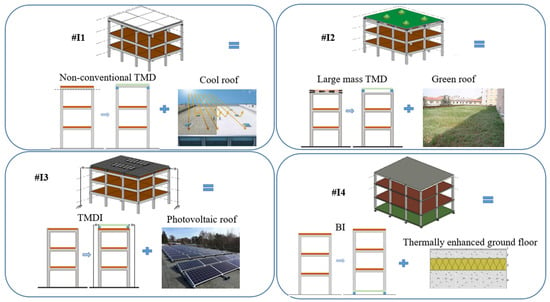
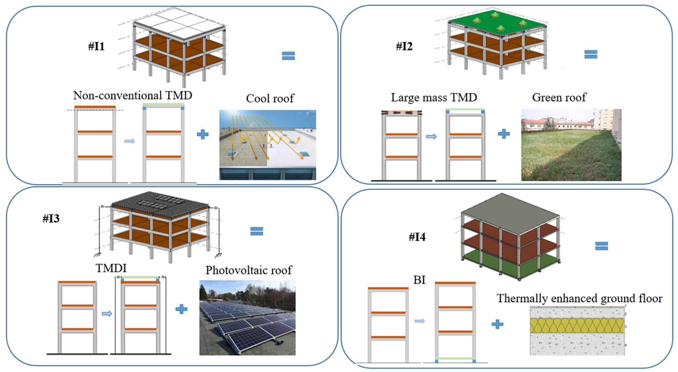
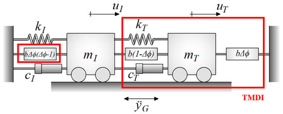
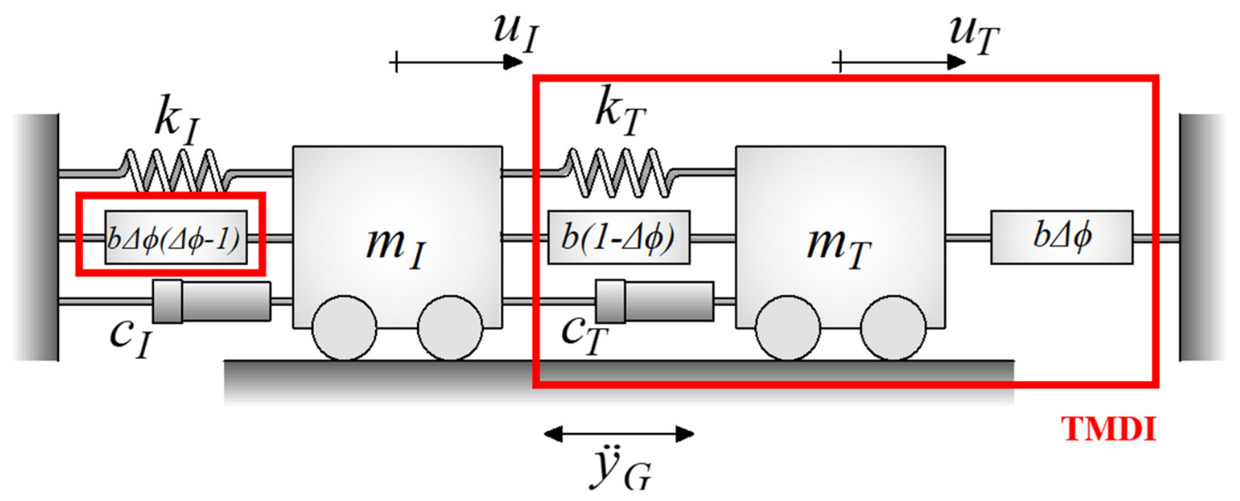
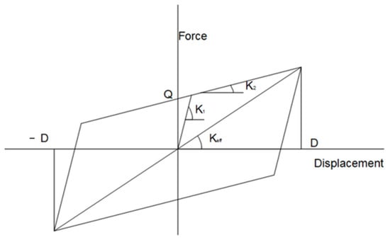
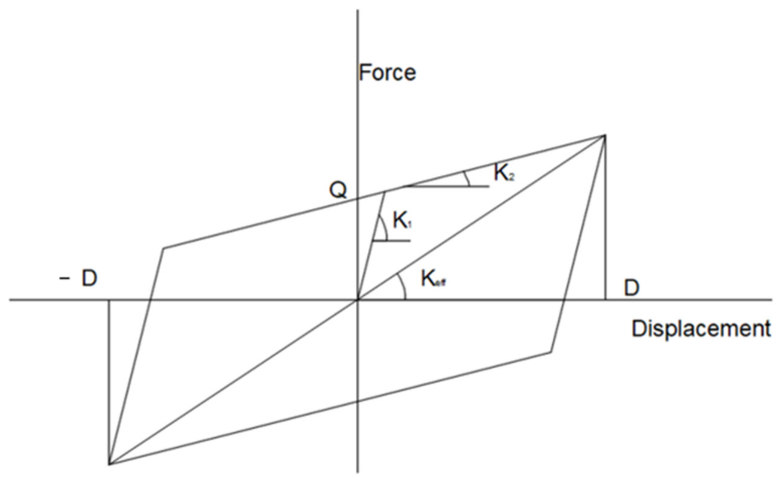
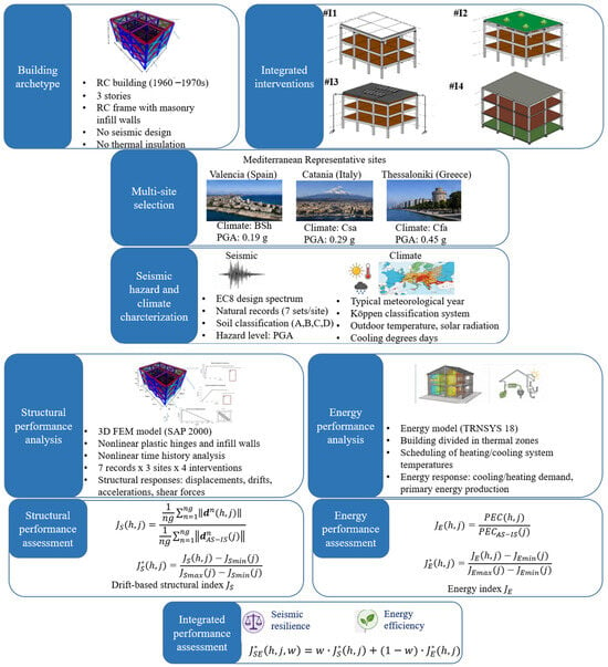
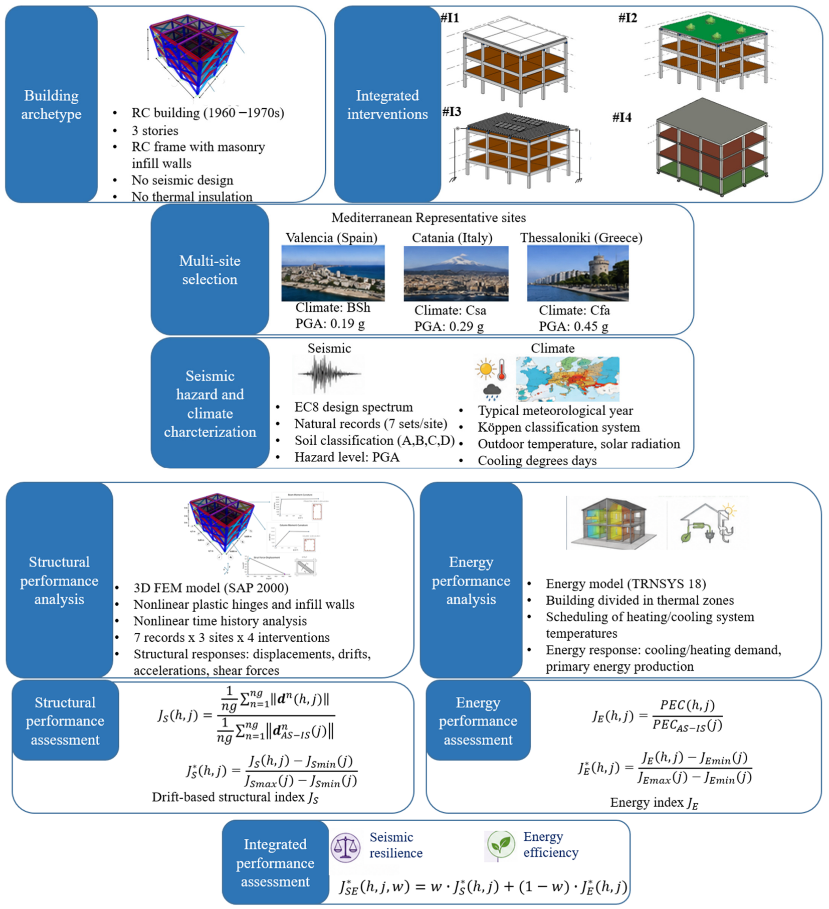
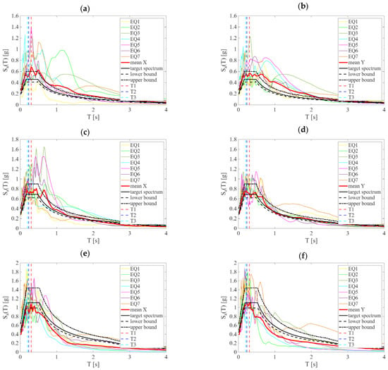
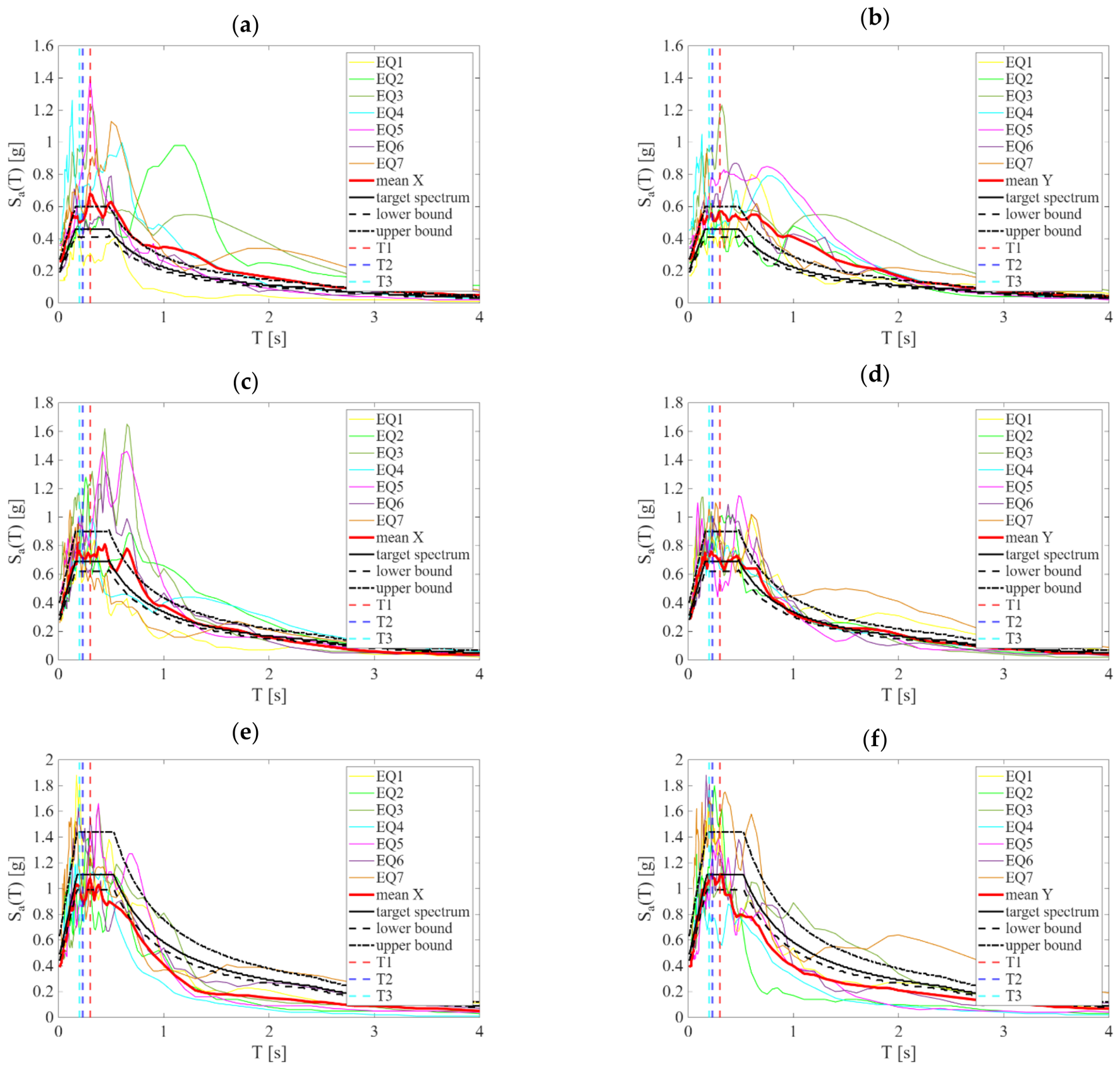
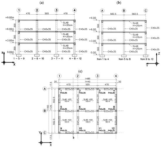
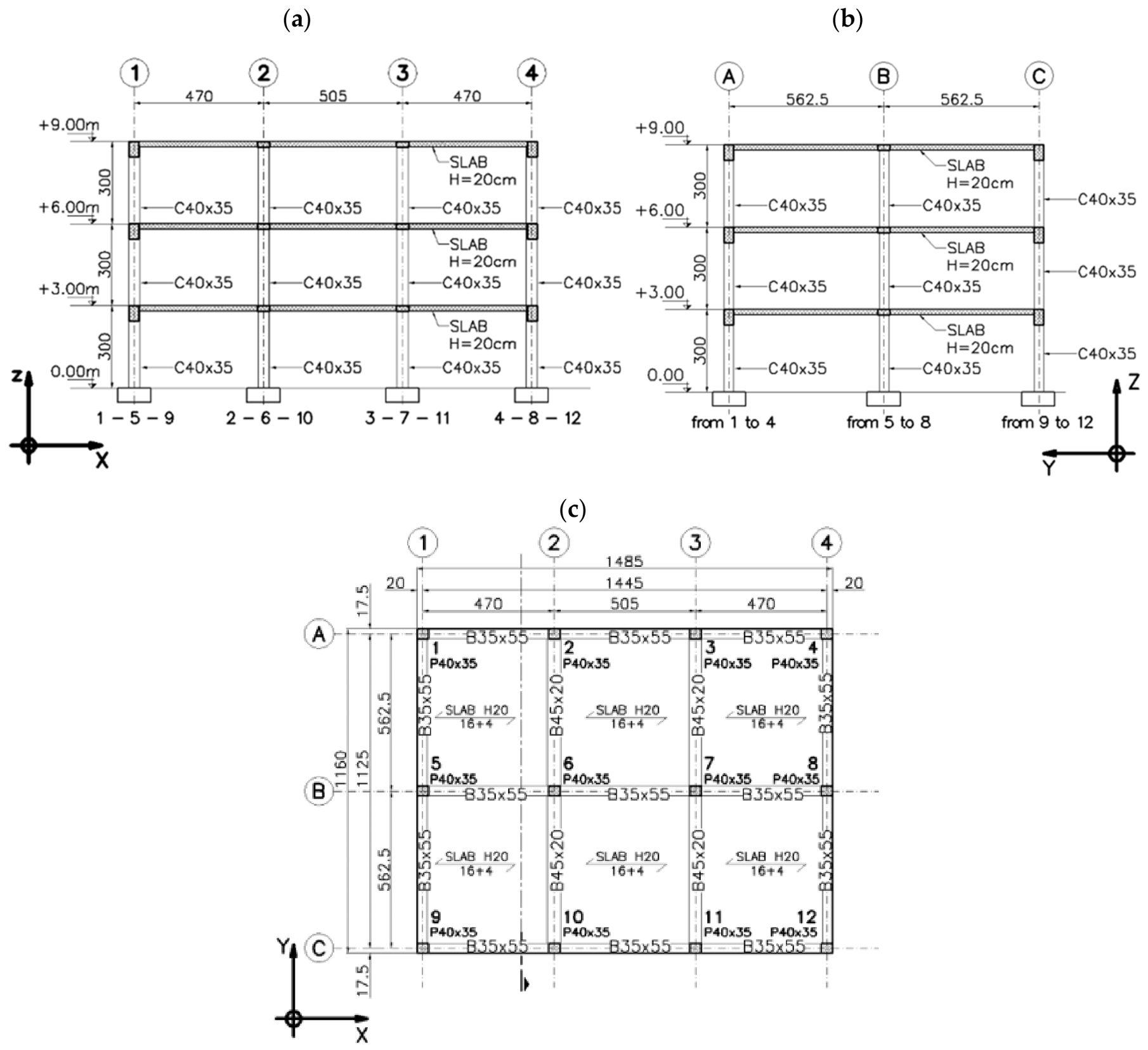
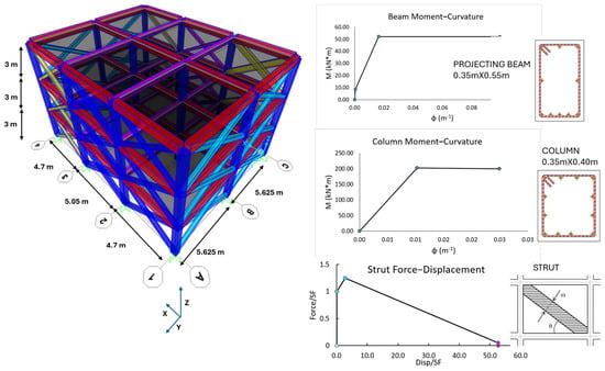
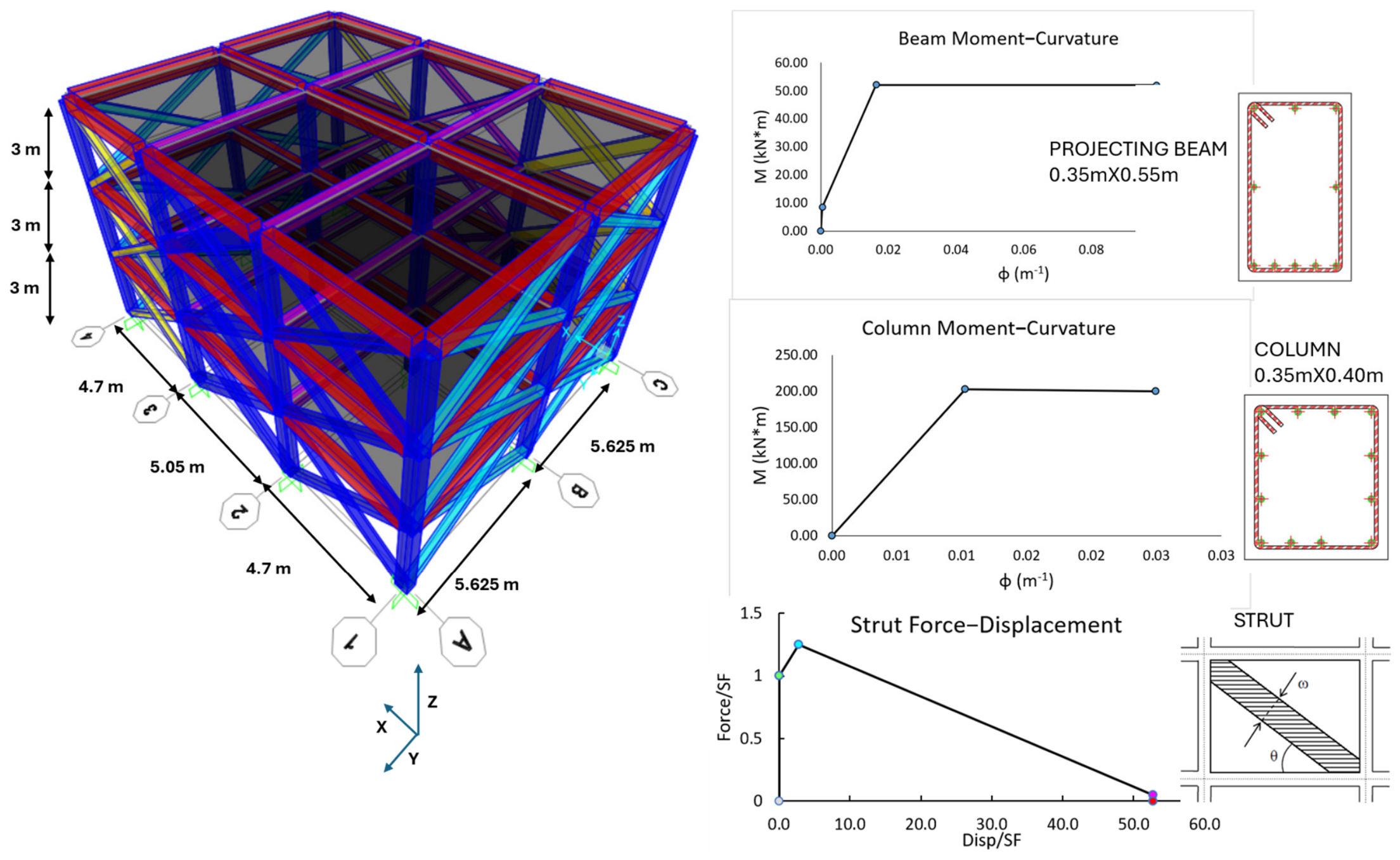
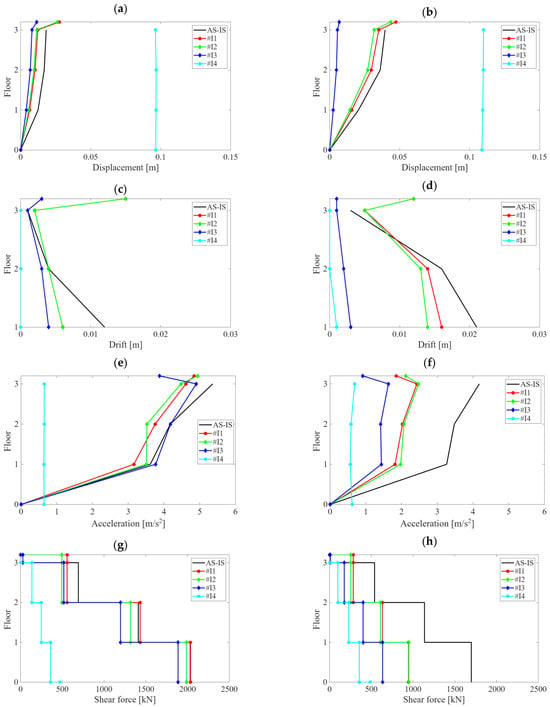
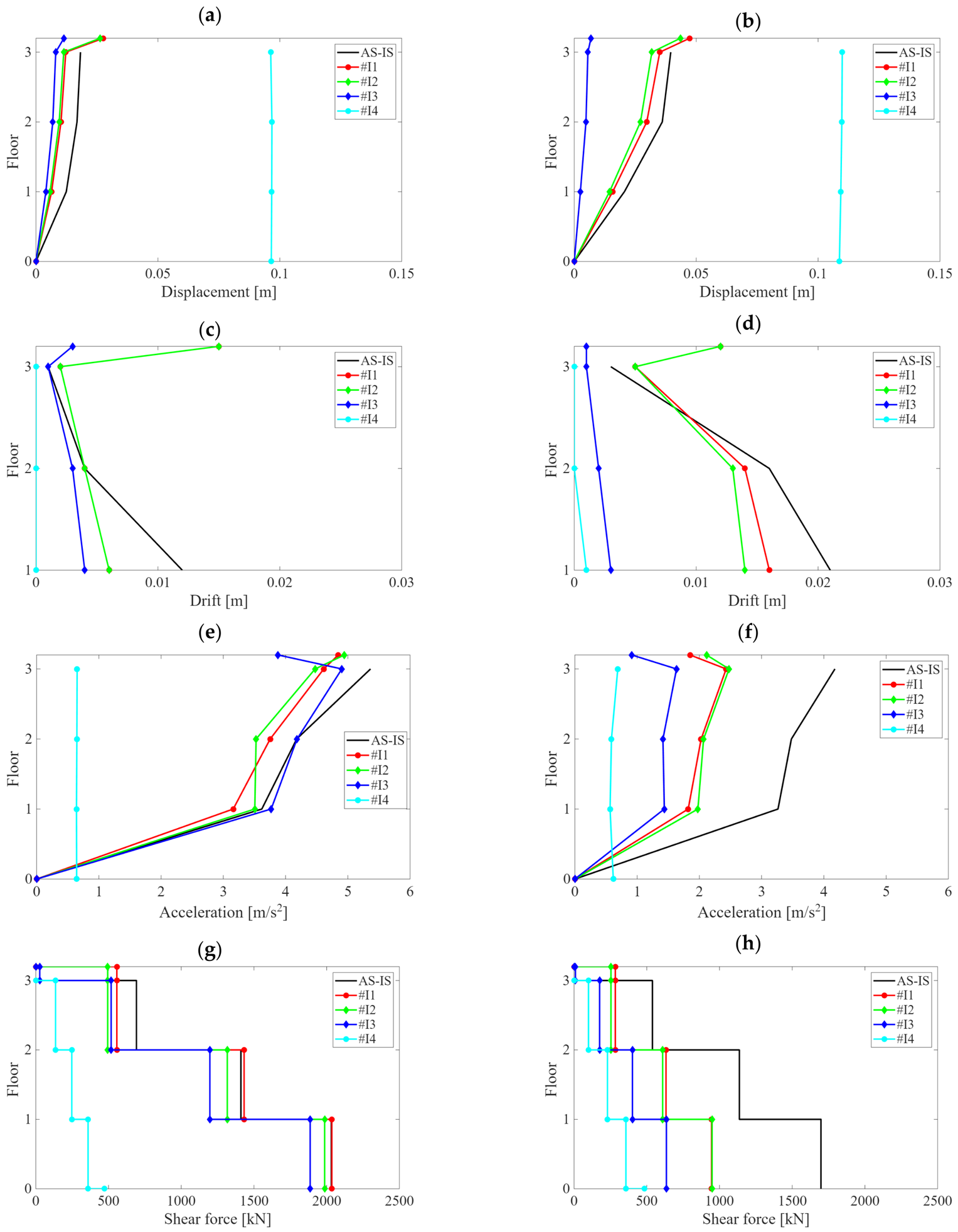
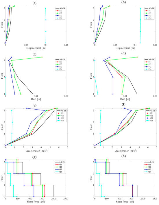
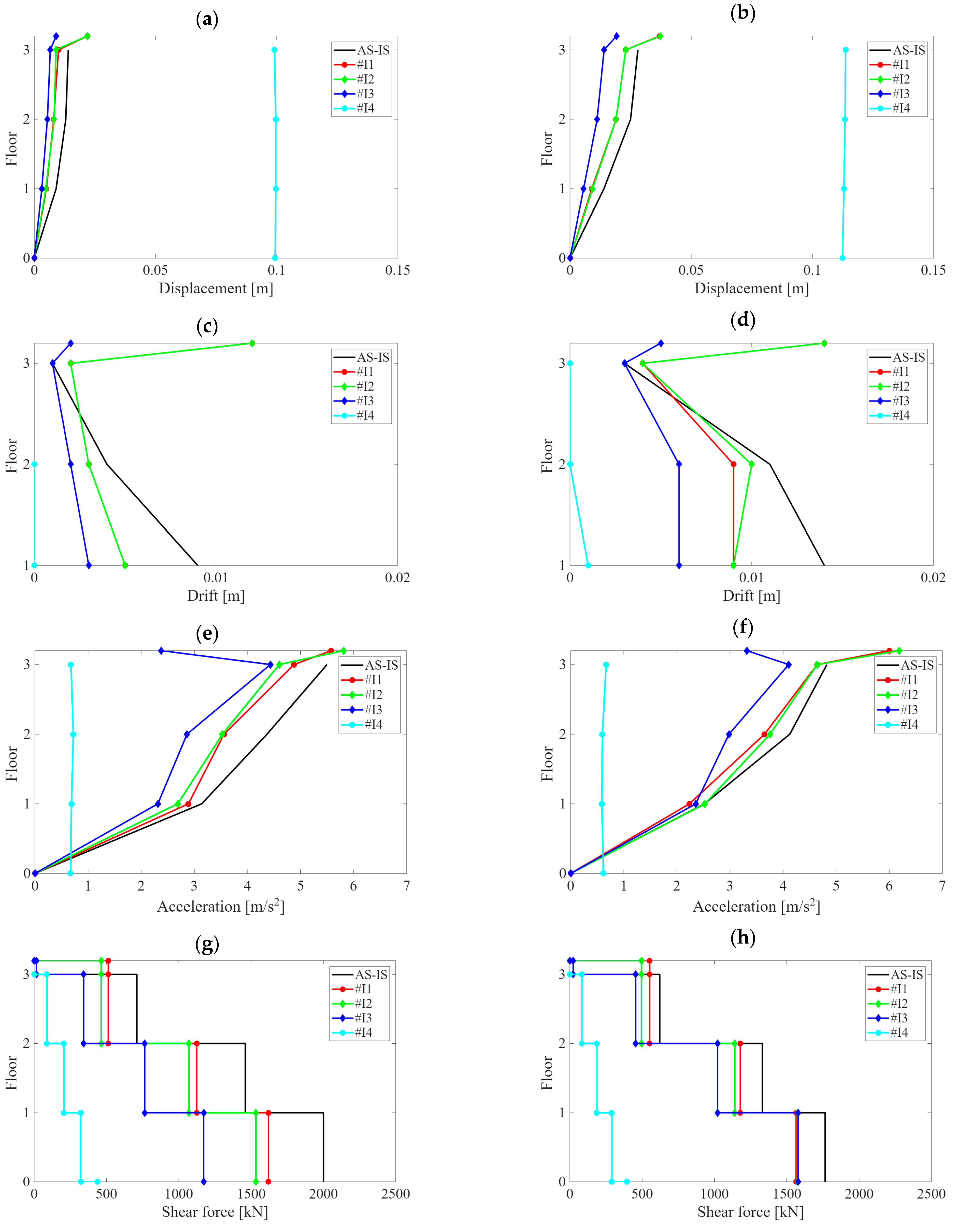
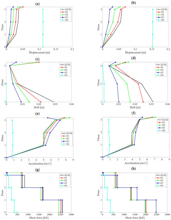
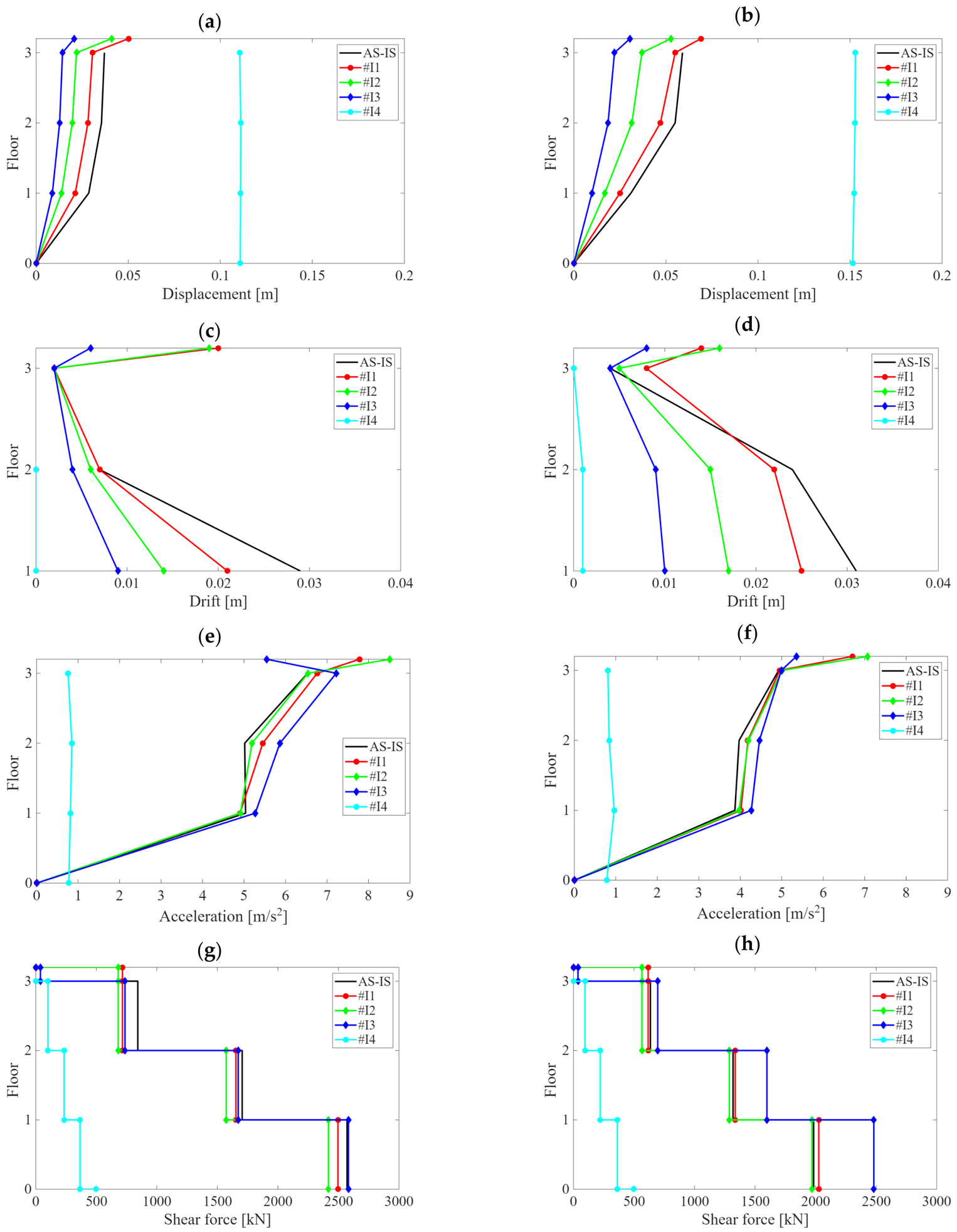
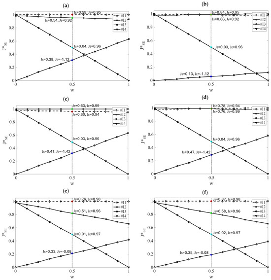
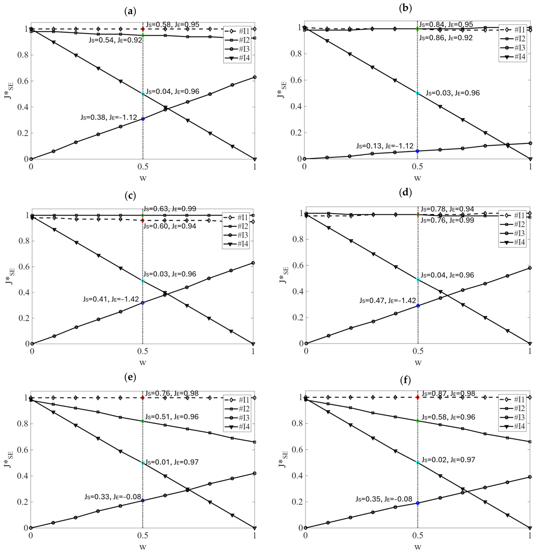

Disclaimer/Publisher’s Note: The statements, opinions and data contained in all publications are solely those of the individual author(s) and contributor(s) and not of MDPI and/or the editor(s). MDPI and/or the editor(s) disclaim responsibility for any injury to people or property resulting from any ideas, methods, instructions or products referred to in the content. |
© 2026 by the authors. Licensee MDPI, Basel, Switzerland. This article is an open access article distributed under the terms and conditions of the Creative Commons Attribution (CC BY) license.