


Abstract
Energy transition has established hydrogen and compressed natural gas (CNG) as key alternatives for reducing greenhouse gas emissions and promoting sustainable mobility in the transport sector. However, the safe deployment of this infrastructure is essential to ensure that decarbonisation strategies remain environmentally, socially and operationally sustainable. Filling stations handling flammable gases may release hydrogen or CNG into open environments where ventilation alone cannot always prevent unacceptable risk situations in populated and industrial areas. Although the current regulatory framework sets out essential design requirements, including safety distances, this article argues that risk management must go beyond minimum compliance, reconsidering the location of detectors, gas dispersion behaviour and the definition of hazard zones. The analysis takes into account the rapid dilution of these gases under open air ventilation conditions and supports a more risk-based approach to infrastructure planning. Since gas supply facilities operating at 25 MPa, the hazard zone from the vehicle receptacle is estimated at 3 m for hydrogen and 1.7 m for CNG. These findings contribute to a safer and more sustainable transport energy infrastructure.
1. Introduction
Under real-world driving conditions, pollutant emissions are significantly reduced in vehicles powered by natural gas [1], whether liquefied (LNG) [2] operating at low pressure [3] or high-pressure compressed natural gas (CNG) [4,5], demonstrating lower fuel consumption compared to petrol [6] and being non-existent in hydrogen vehicles. Although the use of natural gas as an alternative to diesel results in an increase in hydrocarbon emissions to the atmosphere due to unburned methane, this issue can be mitigated with proper engine tuning [7]; furthermore, the addition of hydrogen to natural gas improves fuel efficiency [8]. Consequently, the need to control environmental pollution linked to vehicle emissions [9], combined with the current transition towards more sustainable and cleaner energy sources, makes hydrogen and natural gas increasingly sought-after alternatives [10].
However, the infrastructure required to supply these alternative fuels presents a greater risk [11,12,13], and the importance of optimising service stations [9,14], managing their risks [15], and the potential for incorporating artificial intelligence to ensure their reliability, stability and safety [16,17,18,19] are the subject of ongoing development.
The probability of a catastrophic event such as a jet fire or flash fire and explosion scenarios at a petrol station—caused by a leak of methane [14], compressed natural gas (CNG) [5,11,20,21], and hydrogen [16,22,23,24]—demonstrates that the extent of the area at risk of fatalities associated with them is incompatible with their installation in urban or residential areas [5,15].
Consequently, the prevention of leaks in distribution lines [24,25], safety in transport [12] and at both CNG [4,21] and hydrogen [22,26,27] filling stations, as well as accident prevention and emergency management [22,23,28,29,30,31,32,33,34], have become a priority.
2. Materials and Methods
Refuelling areas, for both hydrogen and compressed natural gas, are always situated in sufficiently open locations that are considered outdoor environments [35]; in both cases, these gases are lighter than air and tend to rise to higher levels where ventilation is more effective. This situation allows the minimum effective air velocity for localised methane leaks to be set at 0.5 m/s at a height of less than 2.0 m above ground level and 1 m/s above that level. However, in the case of very light gases emitted at high pressures, such as hydrogen, buoyancy causes them to disperse, and an increase in effective ventilation velocity is considered safe [36,37]; in this case, effective dilution is considered to occur at an air velocity of 1.0 m/s even at heights below 2.0 m.
Connectors intended for refuelling land vehicles consist of a receptacle and a protective cap mounted on the vehicles, a nozzle and communication hardware [38,39]. The nozzles and sockets are designed and tested to prevent refuelled vehicles from being filled to working pressures or flow rates exceeding the design values, thereby minimising the possibility of incorrect assembly; they are also protected against displacement, distortion and deformation and constructed to maintain functional integrity under normal and reasonable handling conditions. In all performance, durability, ageing, strength, deformation, contamination, thermal cycling and user abuse tests, leaks are checked, with the permissible leakage rate for both hydrogen and CNG set at 20.0 cm3/h [38,39].
The design temperature for fuel distribution and supply systems ranges from −40 °C to 50 °C for hydrogen [40] and from −40 °C to 60 °C for CNG [41].
Vehicles that use hydrogen as fuel are classified according to the pressure at which it is stored in their storage system [42], the minimum pressure required in a vehicle’s containment system to allow refuelling is 0.5 MPa [40], with two additional pressures defined: the maximum filling pressure [38] and the maximum permissible pressure at the dispenser [35].
The maximum filling pressure during refuelling is defined by the following equation [35,38,43]:
where:
- MOP = maximum filling pressure during normal refuelling (Pa).
- NWP = nominal working pressure or stabilised pressure: the pressure in a vehicle’s compressed hydrogen storage system when the tank is full and the gas temperature is 15 °C. (Pa).
- HSL = operating pressure of the hydrogen dispenser (Pa).
The maximum permissible pressure at the dispenser [35] is obtained using the follo-wing equation:
where:
- PS = minimum nominal pressure of the dispenser component (Pa).
- HSL = hydrogen dispenser operating pressure (Pa).
The pressures on the supply of the various types of hydrogen-powered vehicles are (Table 1):
Table 1.
Nominal pressures of supply connectors [35,38,42].
The maximum hydrogen flow rate is 60.0 g/s, although 90.0 g/s can be achieved by using a suitable nozzle in conjunction with a specific filling protocol; flow rates of up to 120 g/s can even be achieved with H35HF high-flow nozzles [40].
The operating pressure at CNG connectors is 20.0 MPa (200 bar) and 25.0 MPa (250 bar) [39], with the maximum filling pressure being 1.3 times the nominal pressure [41].
The system interrupts the fuel supply after 5 s if it detects a drop in flow rate of 1% in the case of hydrogen [40] and 10.0% for CNG [41].
Furthermore, the decoupling device must, when separating under pressure, cut off the gas flow within a maximum of 1 s and allow downstream venting through an orifice with an equivalent diameter of 1.0 mm (+/−0.1 mm) [41].
The maximum permissible fuel losses, for both hydrogen and CNG, are 20.0 cm3/h (at 20 °C) [38,39], a value similar to the structural losses of appliances fuelled by piped gas, which are 5.6 × 10⁻⁹ kg/s [36,37]. In vehicle nozzles and receptacles, gas losses are attributable to undesirable events, whereas in the case of safety valves and vents, emissions to the atmosphere are to be expected during normal operation of the system [36,37]; these devices are never located in the vehicle refuelling area.
The amount of gas released into the atmosphere as a result of a leak is calculated using the following equation [36]:
where:
- wg = leak rate of the flammable substance (kg/s).
- cd = discharge coefficient (m2/h).
- S = opening section, the hole through which the gas escapes (m2).
- Z = compressibility factor of gases (dimensionless).
- = polytropic index: a coefficient defined in terms of the ratio = Cp/Cv.
- T = fluid temperature (°K).
- M = molecular weight (gr/mol).
- Pa = atmospheric pressure (Pa).
- P = absolute pressure of the containment system (Pa).
In the event of a containment system failure, the typical opening area for a connection or valve is between 0.025 mm2 and 0.1 mm2, whilst for pump nozzles it is considered to be 0.25 mm2 [36,37].
The characterisation of the hazard posed by the leak, based on the composition of the fuel [44,45], is carried out using the following equation [36]:
where:
- LRC = leak characterisation (m3/s).
- wg = leak rate of the flammable substance (kg/s).
- LII = lower explosive limit (vol./vol.).
- k = safety factor (dimensionless).
- ρg = gas density (kg/m3).
In the refuelling area, ventilation is considered adequate as it is an open air space [35]; however, its reliability is not guaranteed, as it depends on weather conditions. The air flow rate required to dilute the leaked gas is calculated using the following equation [36]:
where:
- Qmin = ventilation flow rate (m3/s).
- wg = leakage rate of the flammable substance (kg/s).
- LIEm = lower explosive limit (kg/m3).
- k = safety factor (dimensionless).
- k = 0.25 for connections, valves, nozzles and vehicle receptacles.
- k = 0.5 for safety valves and vents.
- ρg = gas density (kg/m3).
- T = ambient temperature (°K).
The relationship between the required ventilation flow rate and the available flow rate in the vicinity of the ventilation outlet determines the hazardous volume within which the concentration of gas in the air may ignite [36,37,46]:
where:
- Qmin = ventilation flow rate (m3/s).
- C = number of air changes (s−1).
Dispersion occurs rapidly enough in the open air that the atmosphere is considered homogeneous within a hypothetical cube with 15.0 m sides; assuming an effective air velocity of 0.5 m/s, the available ventilation rate is 0.003 s−1 [37,47].
It is assumed that the hazard zone generated by the emission at the connection between the nozzle and the vehicle’s receptacle is conical, with a radius that increases with the volume of the exhaust gases according to the following equation:
where:
- r = radius of the cone (m).
- h = height of the cone (m).
The time required for the flammability hazard to disappear once the emission of gas into the atmosphere has ceased is obtained using the following equation [35]:
where:
- Xo = initial gas concentration in the atmosphere (kg/m3).
- C = air change rate (s−1).
- LIEm = lower explosive limit (kg/m3).
- f = safety factor for imperfect dilution (dimensionless).
- k = safety factor (dimensionless).
- k = 0.25 for connections, valves, nozzles and vehicle receptacles.
- k = 0.5 for safety valves and vents.
Given the behaviour of the gases released into the atmosphere, it is assumed that the danger zone is conical in shape, with its apex located at the junction between the nozzle and the vehicle’s fuel tank [36,37].
The physical quantities that characterise the gases under study are shown in Table 2.
Table 2.
Physical properties [37].
3. Results
To avoid the use of statistical atmospheric values, which are only valid at specific locations, standardised air velocities are used to calculate hazard zones at risk of fire and explosion; these are conservative and ensure a high level of safety for any site [36,37].
Permissible fuel losses during the refuelling of hydrogen or CNG vehicles generate very small volumes of hazardous gas, meaning that the area is reclassified as safe provided there is adequate ventilation [36,37], 2.23 cm3 in the case of hydrogen and 0.25 cm3 for CNG. However, the area cannot be considered safe if reliance is placed solely on natural ventilation, given its unreliability [36], or if refuelling takes place at sites that do not meet open-space conditions [36].
These zones have been determined on the basis of supply flow rates of between 60 and 90 g/s for hydrogen and 54.0 g/s for CNG, as well as a maximum flow rate of 120.0 g/s and 200.0 g/s for the H35/70 and H35HF vehicles, respectively [40].
In addition to the gas leaks permitted by design, consideration must also be given to those that do not occur during normal operation and last only for short periods, as they are detected shortly after they begin [36].
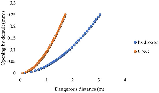
The risk areas resulting from a failure in the 250.0 bar refuelling units, for both hydrogen and CNG vehicles, are as follows [37] (Figure 1):
Figure 1.
Safety distance due to a gas leak whilst refuelling a vehicle at 250 bars.
At 250 bars, a leak in a connection or valve during hydrogen supply (0.025 mm2) creates a hazard zone of 0.9 m, whereas, in the case of CNG, this is reduced to 0.5 m. If the leak occurs at the nozzle or the vehicle’s receptacle (0.25 mm2), a hazard zone of 3.0 m will be created for hydrogen and 1.7 m for CNG. In all cases, these will be classified as Zone 2 [36,37,41].
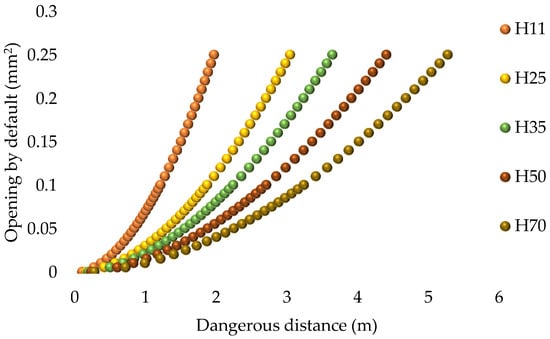
The design standards for refuelling stations do not specify different hazard distances for each type of vehicle; however, they are linked to the supply pressure (Figure 2):
Figure 2.
Safety distance due to a hydrogen leak whilst refuelling a vehicle.
The volume of the danger zone associated with the size of the leak increases in proportion to the supply pressure.
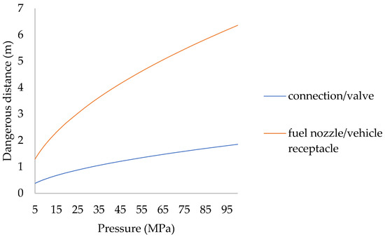
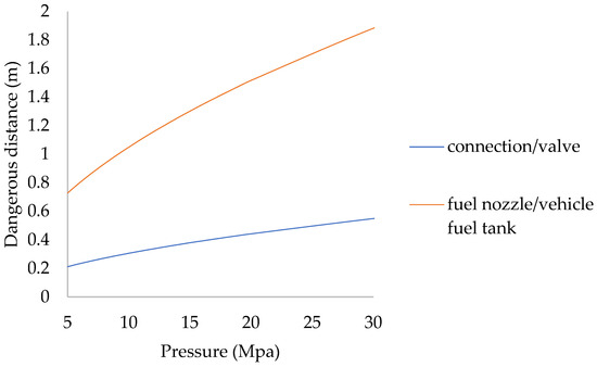
Distribution systems do not supply vehicles with a pressure lower than 0.5 MPa or higher than the nominal pressure of the nozzle [40]; distances, depending on the supply pressure, taking into account the typical values for unexpanded openings for connections, valves, fuel nozzles and vehicle sockets [36], are as follows (Figure 3 and Figure 4):
Figure 3.
Safety distance due to a hydrogen leak at a hydrogen refuelling station.
Figure 4.
Safety distance due to a natural gas leak at a CNG filling station.
The risk zone increases by 12.6% when the maximum filling pressure is taken into account, and by 18.46% when the maximum permissible pressure is considered, compared with the value obtained at supply pressure.
The safety distance increases by 15.0% when the maximum permissible pressure at the outlet is taken into account, compared with that obtained at the supply pressure.
The hazard zones to be taken into account in the components of gas supply units are as follows (Table 3 and Table 4):
Table 3.
Danger zones around components of H2 refuelling units.
Table 4.
Dangerous distances between components of CNG supply units.
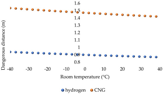
In the design of facilities for the supply of combustible gases, there is a very wide range of ambient temperatures, ranging from −40 °C to 50 °C [41] for hydrogen and from −40 °C to 65 °C for CNG [41]; their influence on safety distances is as follows (Figure 5):
Figure 5.
The effect of temperature on danger zones.
Both the emission rate and the hazard distance decrease as the ambient temperature rises; at −40 °C, they increase by 12.13% and 6.3%, whilst at 50 °C, they decrease by 4.7% and 2.6%, respectively.
The duration of the hazard zone after the emission of flammable gas into the atmosphere has ceased is shown in Table 5.
Table 5.
Duration of hazardous conditions following the cessation of the gas leak.
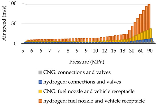
Hazard zones can be made safe by increasing ventilation, so that the dilution of gases is sufficiently high (Figure 6 and Figure 7):
Figure 6.
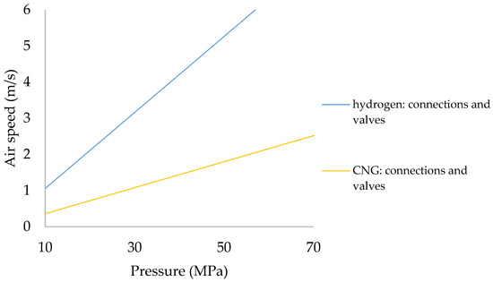
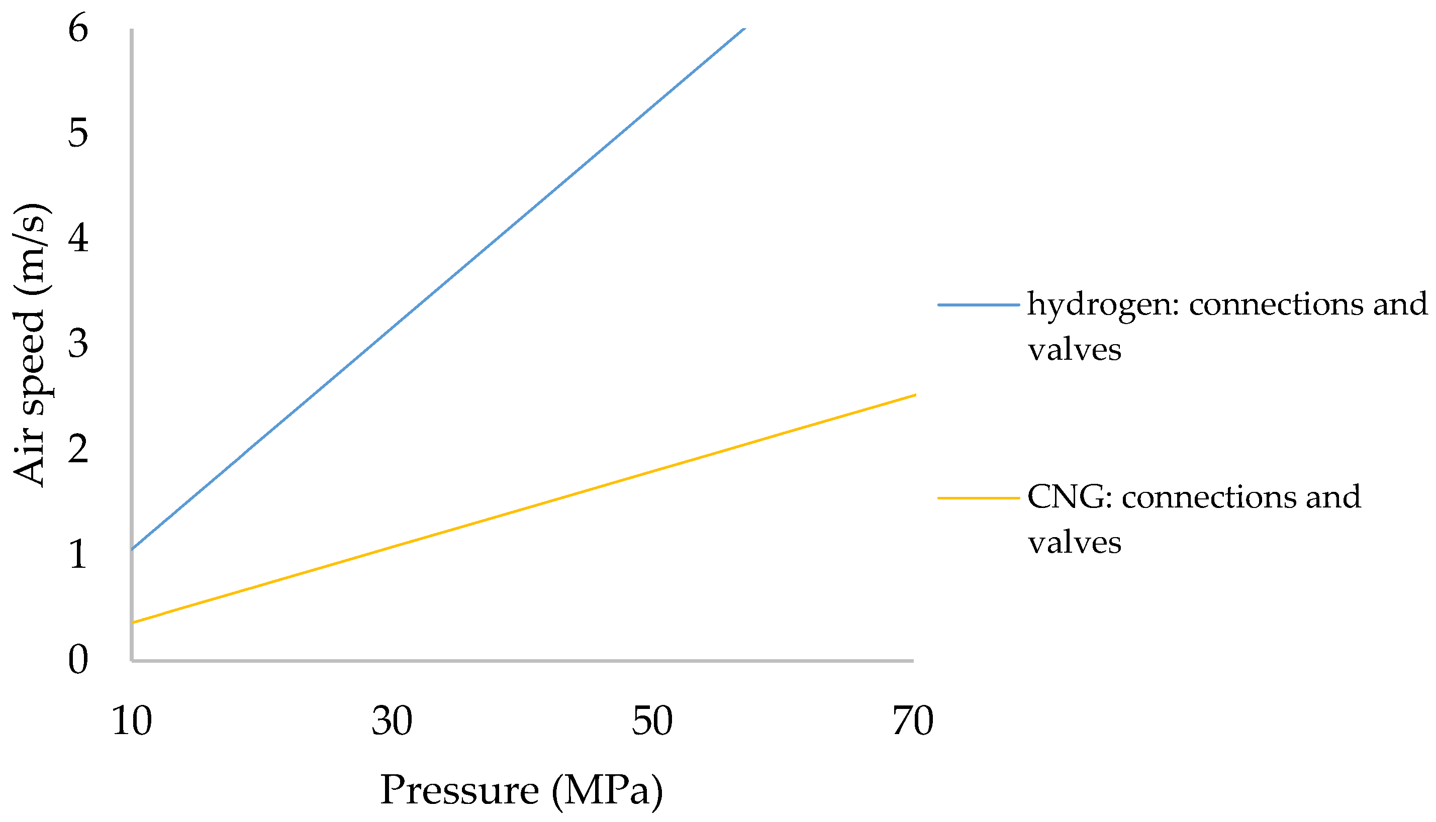
Air velocity to prevent the formation of hazard zones.
Figure 7.
Air velocity to prevent the formation of hazard zone: typical ventilation scenarios.
In a refuelling system for vehicles operating at a pressure of 25.0 MPa, a potential leak in a connection or valve will not result in the formation of a hazard zone provided that an effective air velocity of 2.6 m/s is maintained for hydrogen vehicles and 0.9 m/s for CNG vehicles. Should the failure occur at the fuel nozzle or vehicle receptacle, these values would be 26.4 m/s and 9.0 m/s, which are unattainable even with mechanical ventilation systems.
Given that the effective ventilation rate in open spaces is 1 m/s for hydrogen and 0.5 m/s for methane [36,37], refuelling any vehicle cannot be considered safe in the event of a fault in the refuelling system.
The air velocity required to avoid the imposition of restrictions on activities carried out in the vicinity of high-pressure gaseous fuel supply facilities is as follows (Table 6):
Table 6.
Air velocity required to prevent the formation of hazard zones.
In most cases, the presence of fuel nozzles and sockets for vehicles makes it impossible to decontaminate the surrounding area through ventilation alone.
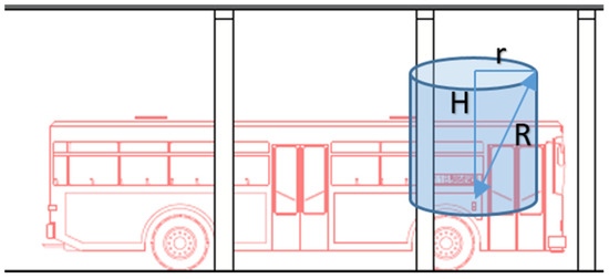
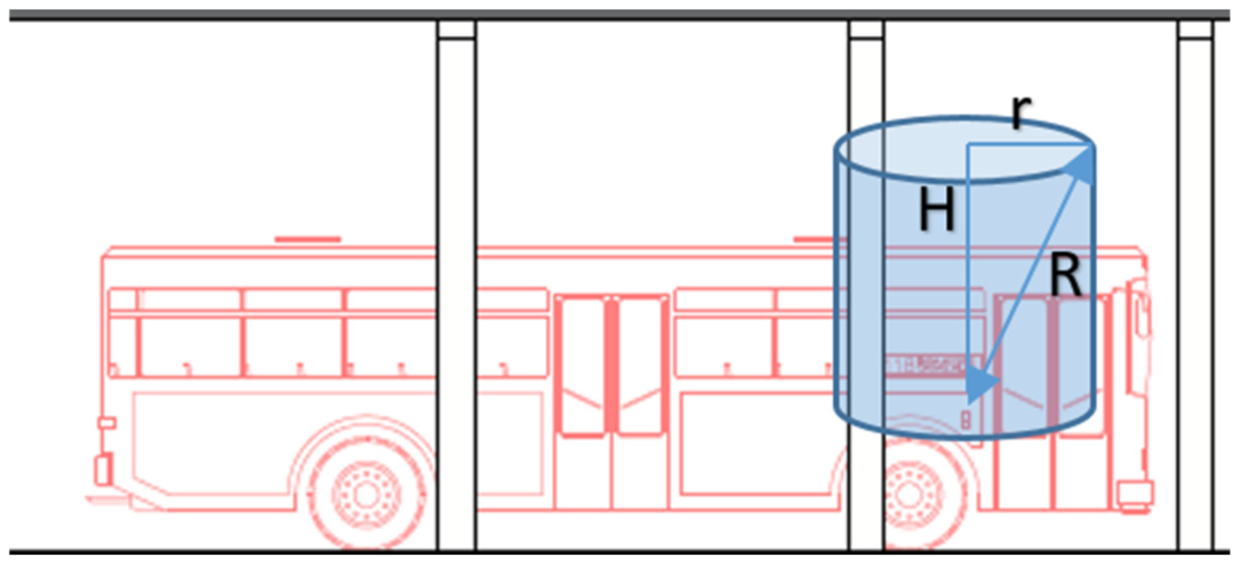
To decontaminate the supply area, such facilities incorporate detectors connected to the gas supply shut-off system; in the case of hydrogen, these are set to 10.0% of the lower flammability limit (LFL), and those for CNG to 30.0% [35,39,40,41]. Design standards prescribe the location of detectors at the top of structures, where gas accumulation is most likely to occur [35,39,40,41]; however, it is essential to adjust the design to account for dilution, as air velocity and the rate of leakage may disperse the gas before it accumulates at the top, which could delay its detection [48,49] (Figure 8).
Figure 8.
Maximum detection range of the sensors relative to the vehicle’s body.
As these are small, high-pressure leaks, they create high-speed jets of gas that dilute and disperse on their own, even without any apparent movement of the air [36].
The maximum distance at which the detectors must be positioned from the supply point, depending on the supply pressure, is shown in Table 7 and Table 8.
Table 7.
Location of H2 detectors.
Table 8.
Location of CNG detectors.
4. Discussion
At fuel stations, the most critical area is the vehicle refuelling zone, as it is accessed by both staff and the general public.
Although service stations have areas classified according to risk and explosion hazard [35,41,50], the standards governing their design, for both gaseous hydrogen and compressed natural gas (CNG), consider that, during the refuelling process, gas leaks are very small and do not give rise to hazard zones, not even during the process of disconnecting the nozzle from the vehicle’s receptacle [35,41]. With the exception of the Guide to The Application of European Standards for Vehicle Refuelling [50].
This disparity between regulatory criteria, coupled with the possibility that the determination of the areas defined by the regulations may be modified by the designer, allows for a classification of risk areas in the refuelling zone based on the probability of component failure and the mitigation measures implemented [35].
Consequently, a critical analysis of service station design standards is required with regard to areas at risk of fire and explosion, focusing in particular on refuelling points for both hydrogen and compressed natural gas (CNG) vehicles.
Furthermore, there are various empirical models which, by using the rate of fuel release into the atmosphere, make it possible to determine parameters such as the incident overpressure, momentum, thermal radiation and dose, which are necessary for assessing the consequences using probabilistic methodologies, whether the leak develops into a fire or an explosion, so that safe distances can also be established to prevent harm to both people and property.
The main limitation of the study lies in the variability of outdoor environmental conditions, which are key factors in determining the atmosphere’s dilution capacity. The results should be improved by applying atmospheric simulation and prediction models.
This paper is not intended to replace engineering design standards; rather, it presents a more conservative estimate in line with risk management.
5. Conclusions
The main innovation of this approach lies in the assumption that the presence of detectors on the ceiling does not, in itself, justify the declassification of the gaseous fuel supply area.
Only in CNG refuelling facilities operating at pressures of up to 25.0 MPa do valves and connections do not create hazard zones in open environments. Although permissible leaks at the dispenser nozzle or the vehicle’s receptacle during refuelling do not give rise to hazard zones, their foreseeable failure necessitates the presence of a detection and shut-off system, as gas emissions into the atmosphere cannot be mitigated by ventilation alone.
Methane leaks tend to return to non-flammable safety conditions at significantly shorter distances than hydrogen; at 25.0 MPa, a containment failure in a connection or valve during hydrogen supply creates a hazard zone of 0.9 m, whereas in the case of CNG this is reduced to 0.5 m. If the failure occurs at the vehicle’s nozzle or receptacle, a hazard zone of 3.0 m will be generated for hydrogen and 1.7 m for CNG.
The positioning of detectors is a key safety consideration for CNG and hydrogen refuelling stations. In addition to placing them in the upper parts of the facility, account must be taken of the rapid dilution of the gas due to ventilation in an open environment, which reduces the concentration of the leak before it reaches the sensor. In a gas supply facility operating at 25.0 MPa, the hydrogen detector must be located at a radial distance of less than 3.2 m from H 25 vehicles; however, for CNG, it must be situated less than 2.0 m from the vehicle’s fuel inlet.
Author Contributions
J.M.B.-Á.: conceptualization, writing—original draft, data curation, methodology, and software. Á.R.-B.: writing—original draft preparation, investigation, writing—review and editing, and project administration. B.M.V.-E.: visualisation, supervision, methodology, formal analysis, and resources. D.d.V.-M.: software, methodology, data curation, and resources. Á.R.-S.: visualisation, supervision, data curation, validation, and resources. All authors have read and agreed to the published version of the manuscript.
Funding
This research received no external funding.
Institutional Review Board Statement
Not applicable.
Informed Consent Statement
Not applicable.
Data Availability Statement
The original contributions presented in the study are included in the article; further inquiries can be directed to the corresponding author.
Conflicts of Interest
The authors declare no conflicts of interest.
Abbreviations
The following abbreviations are used in this manuscript:
| CNG | compressed natural gas |
| LFL | lower flammability limit |
| LNG | liquefied natural gas |
References
- Muhammad Ihsan Shahid, M.I.; Farhan, M.; Rao, A.; Salam, H.A.; Chen, T.; Li, X.; Ma, F. Performance, emissions and thermodynamic analysis of hydrogen-enriched compressed natural gas engine. Therm. Sci. Eng. Prog. 2025, 63, 103643. [Google Scholar] [CrossRef] [Scilit]
- Banaszkiewicz, T.; Chorowski, M.; Gizicki, W.; Jedrusyna, A.; Kielar, J.; Malecha, Z.; Piotrowska, A.; Polinski, J.; Rogala, Z.; Sier-powski, K.; et al. Liquefied Natural Gas in Mobile Applications—Oppor-tunities and Challenges. Energies 2020, 13, 5673. [Google Scholar] [CrossRef] [Scilit]
- IOS 16924:2026; Natural Gas Fuelling Stations—Liquefied Natural Gas (LNG) Stations for Fuelling Road Vehicles. International Organization for Standardization: Geneva, Switzerland, 2026.
- Merkisz, J.; Fuc, P.; Bajerlein, M.; Dobrzynski, M.; Rymaniak, L.; Ziólkowski, A. Reducing the negativeimpact of public transport on the environment by using CNG as a fuel/ograniczenie negatywnego wpl-ywu komunikacji miejskiej na srodowisko naturalne poprzez zastosowanie CNG jako paliwa. J. KONBiN 2012, 22, 147–158. [Google Scholar] [CrossRef] [Scilit]
- Abbasi Kharajou, B.; Ahmadi, H.; Rafiei, M. Quantitative risk estimation of CNG stationby using fuzzy bayesian networks and consequence modeling. Sci. Rep. 2024, 14, 4266. [Google Scholar] [CrossRef] [Scilit] [PubMed]
- Warguła, Ł.; Kukla, M.; Lijewski, P.; Dobrzyński, M.; Markiewicz, F. Impact of Compressed Natural Gas (CNG) Fuel Systems in Small Engine Wood Chippers on Exhaust Emissions and Fuel Consumption. Energies 2020, 13, 6709. [Google Scholar] [CrossRef] [Scilit]
- Lv, L.; Ge, Y.; Ji, Z.; Tan, J.; Wang, X.; Hao, L.; Wang, Z.; Zhang, M.; Wang, C.; Liu, H. Regulated emission characteristics of in-use LNG and diesel semi-trailer towing vehicles under real driving conditions using PE-MS. J. Environ. Sci. 2020, 88, 155–164. [Google Scholar] [CrossRef] [Scilit] [PubMed]
- Farhan, M.; Salam, H.A.; Shahid, M.I.; Tianhao Chen, T.; Xiao, Q.; Jiang, L.; Anas Rao, A.; Li, X.; Ma, F. Experimental and predictive advancements in hydrogen enriched compressed natural gas spark ignition engines: A critical review. Fuel 2026, 407, 137248. [Google Scholar] [CrossRef] [Scilit]
- Ding, Y.; Ji, Z.; Liu, P.; Wu, Z.; Li, G.; Cui, D.; Wu, Y.; Xu, S. Gas Station Recognition Method Based on Monitoring Data of Heavy-Duty Vehicles. Energies 2021, 14, 8011. [Google Scholar] [CrossRef] [Scilit]
- EU. Directive 2014/94/EU of the European Parliament and of the Council of 22 October 2014 on the Deployment of Alternative Fuels Infrastructure Text with EEA Relevance; EU: Strasbourg, France, 2014. [Google Scholar]
- Ali, Y.; Ahsan Younus, A.; Khan, A.U.; Alrefai, A.H. Compressed Natural Gas (CNG) as a fuel and the associated risks: A quantitative analysis in the scenario of a developing country. J. Saf. Sci. Resil. 2024, 5, 306–316. [Google Scholar] [CrossRef] [Scilit]
- Gholamizadeh, K.; Chia Rostami, C.; Zarei, E.; Yazdi, M.; Sarbast Moslem, S. Advancing hazardous materials transport safety: Systematic insights on risks, challenges, and research gaps. J. Saf. Sci. Resil. 2026, 7, 100226. [Google Scholar] [CrossRef] [Scilit]
- Pereira, R.; Monteiro, V.; Afonso, J.L.; Teixeira, J. Hydrogen Refueling Stations: A Review of the Technology Involvedfrom Key Energy Consumption Processes to Related Energy Management Strategies. Energies 2024, 17, 4906. [Google Scholar] [CrossRef] [Scilit]
- Kagiri, C.; Zhang, L.; Xia, X. Optimal energy cost management of a CNG fuelling station. IFAC-PapersOnLine 2017, 50, 94–97. [Google Scholar] [CrossRef] [Scilit]
- Aliabadi, M.M.; Gholamizadeh, K. Locating urban CNG stations using quantitative riskassessment: Using the Bayesian network. Saf. Reliab. 2021, 40, 48–64. [Google Scholar] [CrossRef] [Scilit]
- Zúñiga-Saiz, P.; Sánchez-Díaz, C. Design of a Hydrogen Refueling Station with hydrogen production by electrolysis, storage and dispensing for a bus fleet in the cityof Valencia. Int. J. Hydrogen Energy 2025, 104, 651–664. [Google Scholar] [CrossRef] [Scilit]
- Arsad, A.Z.; Hannan, M.A.; Ong, H.C.; Ker, P.J.; Wong, R.T.K.; Begum, R.A.; Jang, G.; Mahlia, I.T.M. Artificial intelligence in hydrogen energy transitions: A comprehensive survey and future directions. Renew. Sustain. Energy Rev. 2025, 224, 116121. [Google Scholar] [CrossRef] [Scilit]
- Dev, A.; Kumar, V.; Tummala, A.S.L.V. Charting the hydrogen fuel technology: Pathways and challenges. Discov. Appl. Sci. 2025, 7, 1336. [Google Scholar] [CrossRef] [Scilit]
- Hossain, M.A.; Islam, M.R.; Hossain, M.A.; Hossain, M.J. Control strategy review for hydrogen-renewable energy power system. J. Energy Storage 2023, 72, 108170. [Google Scholar] [CrossRef] [Scilit]
- Luo, Z.; Liu, L.; Su, B. Consequence analysis of CNG leakage at joint refueling and charging stations. Process Saf. Prog. 2023, 42, 637–648. [Google Scholar] [CrossRef] [Scilit]
- Li, W.; Shen, X.; Huang, Z. Study of Leakage and Explosion Hazard Characteristics of a Compressed Natural Gas at a Gas Station. J. Eng. Phys. Thermophys. 2024, 97, 387–396. [Google Scholar] [CrossRef] [Scilit]
- Wang, C.; Xing, A.; Chen, X.; Li, Q.; Qu, J.; Deng, J. Research progress on hydrogen leakage behavior and prevention-control technologies of infrastructure in hydrogen refueling stations. Int. J. Hydrogen Energy 2025, 196, 152607. [Google Scholar] [CrossRef] [Scilit]
- Liang, Z.; Yang, Y.; Wang, Y.; Zhang, M.; Zhuang, Y. Multidimensional quantitative modelling fusion analysis of safety risks in hydrogen refuelling stations: A case study of a station in Beijing. J. Loss Prev. Process Ind. 2026, 100, 105865. [Google Scholar] [CrossRef] [Scilit]
- Zhang, J.; Wang, L.; Shi, M.; Li, Z.; Liu, B. Analysis of risk evolution mechanisms for hydrogen leakage in HECS: A dynamic Bayesian network and scenario deduction approach. Int. J. Hydrogen Energy 2025, 163, 150804. [Google Scholar] [CrossRef] [Scilit]
- Butt, T.J.; Amjad, M.; Raza, S.F.; Riaz, F.; Ahmad, S.; Abdollahian, M. Gas Leakage Identification and Prevention byPressure Profiling for Sustainable Supply of Natural Gas. Sustainability 2023, 15, 13604. [Google Scholar] [CrossRef] [Scilit]
- Mielich, T.; Dobler, R.; Hollnagel, J.; Akca, O.; Müller-Kirchenbauer, J. Europe’s way from natural gas to green hydrogen: Modeling and simulation of the transforming European gas transport infrastructure. Int. J. Hydrogen Energy 2025, 135, 156–171. [Google Scholar] [CrossRef] [Scilit]
- Xie, Q.; Zhou, T.; Wang, C.; Zhu, X.; Ma, C.; Zhang, A. An integrated uncertainty analysis method for the risk assessment of hydrogen refueling stations. Reliab. Eng. Syst. Saf. 2024, 248, 110139. [Google Scholar] [CrossRef] [Scilit]
- Wang, X.; Gao, W. Hydrogen leakage risk assessment for hydrogen refueling stations. Int. J. Hydrogen Energy 2023, 48, 35795–35808. [Google Scholar] [CrossRef] [Scilit]
- Jordehi, A.R.; Mansouri, S.A.; Tostado-Véliz, M.; Safaraliev, M.; Hakimi, S.M.; Nasir, M. A tri-level stochastic model for operational planning of microgrids with hydrogen refuelling station-integrated energy hubs. Int. J. Hydrogen Energy 2024, 96, 1131–1145. [Google Scholar] [CrossRef] [Scilit]
- Hoseyni, S.M.; Mostafa, M.O.M.; Cordiner, J. Mitigating risks in hydrogen-powered transportation: A comprehensive risk assessment for hydrogen refuelling stations, vehicles, and garages. Int. J. Hydrogen Energy 2024, 91, 1025–1044. [Google Scholar] [CrossRef] [Scilit]
- Zhang, J.; Zhang, S.; Qiao, J.; Wei, J.; Wang, L.; Li, Z.; Zhuo, J. Safety resilience evaluation of hydrogen refueling stations based on improved TOPSIS approach. Int. J. Hydrogen Energy 2024, 66, 396–405. [Google Scholar] [CrossRef] [Scilit]
- Wang, L.; Zhang, J.; Wang, H.; You, Q.; Zhuo, J.; Zhang, S.; Qiao, J.; Wei, J. Hydrogen leakage risk assessment of HECS based on dynamic bayesian network. Int. J. Hydrogen Energy 2024, 78, 256–267. [Google Scholar] [CrossRef] [Scilit]
- Gao, X.; Chen, G.; Pu, W.; Xiong, C. A mechanistic framework for the leakage risk reduction of mobile hydrogen refueling stations based on inherent safety concepts. Int. J. Hydrogen Energy 2024, 83, 1370–1384. [Google Scholar] [CrossRef] [Scilit]
- Genovese, M.; Fragiacomo, P. Hydrogen refueling station: Overview of the technological status and research enhancement. J. Energy Storage 2023, 61, 106758. [Google Scholar] [CrossRef] [Scilit]
- IOS 19880-1:2020; Gaseous Hydrogen—Fuelling Stations Part 1: General Requirements. International Organization for Standardization: Geneva, Switzerland, 2020.
- EN IEC 60079-10-1:2022; Explosive Atmospheres—Part 10-1: Classification of Areas—Explosive Gas Atmospheres. European Committee for Standardization (CEN): Brussels, Belgium, 2022.
- UNE 20007IN; Application Guide of EN 60079-10: 2006. Electrical Apparatus for Explosive Gas Atmospheres. Classification of Hazardous Areas. European Committee for Standardization (CEN): Brussels, Belgium, 2000.
- IOS 17268-1:2025; Gaseous Hydrogen Land Vehicle Refuelling Connection Devices. Part 1: Flow Capacities up to and Including 120 g/s. International Organization for Standardization: Geneva, Switzerland, 2025.
- IOS 14469:2017; Road Vehicles—Compressed Natural Gas (CNG) Refuelling Connector. International Organization for Standardization: Geneva, Switzerland, 2017.
- EN 17127:2024; Outdoor Hydrogen Refuelling Points Dispensing Gaseous Hydrogen And Incorporating Filling Protocols. European Standard EN/HRS: Brussels, Belgium, 2024.
- IOS 16923:2026; Natural Gas Fuelling Stations—Compressed Natural Gas (CNG) Stations for Fuelling Vehicle. International Organization for Standardization: Geneva, Switzerland, 2026.
- UN 13-1 2023; Hydrogen and Fuel Cell Vehicles. United Nations Global Technical Regulation: Geneva, Switzerland, 2023.
- IOS 10286:2025; Gas Cylinders. International Organization for Standardization: Geneva, Switzerland, 2025.
- IOS 13686:2013; Natural Gas—Quality Designation. International Organization for Standardization: Geneva, Switzerland, 2013.
- IOS 15403-1:2006; Natural Gas—Natural Gas for Use as a Compressed Fuel for Vehicles Part 1: Designation of the Quality. International Organization for Standardization: Geneva, Switzerland, 2006.
- Ballesteros-Álvarez, J.M.; Romero-Barriuso, A.; Villena-Escribano, B.M.; Rodríguez-Sáiz, A.; González-Gaya, C. Investigating the effectiveness of a new indoor ventilation model in reducing the spread of disease: A case of sports centres amid the COVID-19 pandemic. Heliyon 2024, 10, e27877. [Google Scholar] [CrossRef] [Scilit] [PubMed]
- Romero-Barriuso, Á.; Ballesteros-Álvarez, J.M.; Villena-Escribano, B.M.; Rodríguez-Sáiz, Á.; González-Gaya, C. Occupancy and Air Quality Model for Outdoor Events: A Strategy for Preventing Disease Transmission at Mass Events. Buildings 2025, 15, 677. [Google Scholar] [CrossRef] [Scilit]
- IEC 60079-29-2; Gas Detectors—Selection, Installation, Use and Maintenance of Detectors for Flammable Gas and Oxygen. European Committee for Standardization (CEN): Geneva, Switzerland, 2015.
- IEC 60079-29-4; Gas Detectors—Performance Requirements of Open Path Detectors for Flammable Gases. European Committee for Standardization (CEN): Geneva, Switzerland, 2009.
- EN-CEN/TR 17452:2020; Natural Gas Fuelling Stations—Guidance for Implementation of European Standards on CNG and LNG Stations for Fuelling Vehicles. European Standard: Brussels, Belgium, 2020.

Disclaimer/Publisher’s Note: The statements, opinions and data contained in all publications are solely those of the individual author(s) and contributor(s) and not of MDPI and/or the editor(s). MDPI and/or the editor(s) disclaim responsibility for any injury to people or property resulting from any ideas, methods, instructions or products referred to in the content. |
© 2026 by the authors. Licensee MDPI, Basel, Switzerland. This article is an open access article distributed under the terms and conditions of the Creative Commons Attribution (CC BY) license.