


Abstract
Reusing cast-in-place (CIP) concrete elements could enhance the sustainability of the construction industry by enabling circularity, preserving embodied value, and reducing primary resource consumption, construction and demolition waste, and emissions from new concrete production. However, the implementation of such reuse is hindered by project-specific geometries, monolithic connections, and complex coordination requirements. Existing process representations address individual aspects of reuse, but an integrated process framework for coordinating assessment, dismantling, logistics, and reuse across multiple actors and projects is still lacking. To address this gap, this study develops a concept for a process-driven digital ecosystem supporting the circular reuse of CIP concrete elements within the Collaborative Research Centre 1683. Literature-based process representations are analysed, translated into Business Process Model and Notation (BPMN), and synthesised into domain-specific process models. The resulting models formalise the reuse chain, clarify actor responsibilities and information flows, and support the identification of technical, temporal, and spatial dependencies. Building on this formalisation, a conceptual digital ecosystem is derived that links information on reusable elements with process logic and reuse-related decision-making. The concept centres on a construction kit (CK) as a standardisation layer and an element data store (EDS) as the information basis for traceability, coordination, and matching. The results provide a structured foundation for digitally supported sustainability-oriented circular construction and for future ontology integration, process simulation, and decision-support applications.
1. Introduction
1.1. Motivation
The construction industry is one of the most resource-intensive sectors worldwide and a major contributor to environmental impacts due to material extraction, processing, and waste generation. It is responsible for a considerable share of global greenhouse gas (GHG) emissions [1] and, in many regions, accounts for more than one-third of total waste generation [2]; in Germany, this proportion exceeds 50% [3].
In the construction sector, concrete is the most widely used material worldwide [4] and therefore plays a central role in reducing the environmental footprint of the construction industry. In Germany alone, approximately 47 million m3 (around 110 million tonnes) of concrete are used annually in construction, while global cement production amounts to around 3.1 billion tonnes per year [5]. Thus, concrete, especially because of its key binding ingredient, cement, is responsible for approximately 7% of global GHG emissions according to the Cement Industry Net Zero Progress Report 2024/25 by the Global Cement and Concrete Association (GCCA) [6]. This highlights the need for a fundamental shift away from predominantly linear construction practices towards more sustainable, circular approaches.
To date, this transformation has primarily focused on recycling strategies. Zabek et al. [7] report that the use of recycled concrete as aggregate is already common practice in Germany. However, they demonstrate that this predominantly results in downcycling. Although recycled concrete can be used, for example, as road fill, the cement it contains cannot be recovered. Consequently, the energy- and emission-intensive production of new cement remains unavoidable. Reducing primary cement demand and limiting construction and demolition waste therefore present a key challenge for improving the sustainability of the construction sector. According to Rockström et al. [8], significant emission reductions can be realised through material choices, improved material efficiency, and increased use of secondary resources. This work focuses on the potential to expand the use of secondary resources. Against this background, the reuse of concrete elements emerges as a promising alternative to recycling, as it enables the preservation of existing cement. By maintaining the functional value of existing concrete beyond a single life cycle, reuse has the potential to significantly reduce raw material consumption and landfill demand. This approach aligns with the goals set out in the European Waste Framework Directive (WFD) and the German Resource Efficiency Programme (ProgRess III) [9,10].
In this context, the existing building stock can be understood as a substantial material reservoir. In Germany, there are approximately 51.6 million buildings, containing an estimated 10 billion tonnes of concrete [11]. In 2022, more than 12,000 residential buildings were demolished [12]. As outlined by Devènes et al. [13], a significant proportion of demolitions, particularly of reinforced-concrete buildings, is driven not by degradation but by socio-economic factors. This indicates considerable potential for the reuse of concrete elements. Leveraging this existing stock could enable the supply of materials associated with significantly lower greenhouse gas emissions than those arising from new concrete production. Nevertheless, despite this potential, the practical application of circular economy principles in construction remains limited and is still in its early stages [14].
One of the main reasons for this limited application is the high complexity associated with the practical implementation of concrete element reuse, particularly for cast-in-place (CIP) concrete elements. Devènes et al. [13] indicate that integrating recovered load-bearing elements affects both the deconstruction process of the source building and the design and construction processes of the target building. Coordinating dismantling, logistics, processing, storage, and reinstallation across multiple actors and locations entails strong technical, temporal, and spatial interdependencies that significantly complicate planning and decision-making. As a result, circular construction efforts have so far focused primarily on recycling rather than on the reuse of CIP concrete elements, leaving the substantial environmental benefits of reuse largely unrealised in practice.
1.2. Research Gap and Objective
The transition from linear to circular construction has proven to be challenging and has largely centred on recycling rather than reuse. Previous research has shown that while the reuse of entire building components offers significant potential to enhance material circularity in the construction sector, its implementation remains limited due to a complex interplay of economic, social, and regulatory barriers, with stakeholder perceptions strongly influenced by associated risks [15]. This underlines the need for standardised and formalised approaches. Initial research has explored the reuse of construction elements, particularly from steel structures [16,17,18], timber structures [18,19], and precast concrete structures [20,21]. These studies demonstrate that reuse is technically feasible and can achieve environmental benefits when elements are modular, standardised, and detachable.
Despite its widespread use, the reuse of CIP concrete elements remains largely unexplored. In 2024, approximately 36.8 million m3 of ready-mixed concrete was produced in Germany [22], highlighting the widespread use of CIP concrete construction. Unlike precast elements, CIP concrete elements are typically characterised by a high degree of geometric freedom and project-specific design rather than standardised modularity. Although this flexibility is advantageous during construction, it poses a major challenge for reuse, where compatibility, repeatability, and modularity are crucial. The lack of standardisation in terms of dimensions and load-bearing capacity makes it difficult to identify elements that can be assigned to new structures.
In addition, CIP concrete elements are usually connected monolithically, resulting in structural connections that are more difficult to detach than mechanical joints commonly used in steel, timber, or precast concrete construction. The dismantling of such elements therefore requires complex technical procedures and careful planning, further increasing organisational and logistical complexity. These characteristics fundamentally distinguish the reuse of CIP concrete elements from reuse approaches developed for other construction types, thereby limiting the direct transferability of existing reuse concepts and process models.
Consequently, there is a lack of frameworks that address the specific challenges associated with the reuse of CIP concrete elements, particularly regarding process coordination, logistics, and the matching of non-standardised elements across distributed source and target buildings.
The overarching aim of this study is to support the reuse of CIP concrete elements by developing a formal process framework for a process-driven digital ecosystem. Existing literature-based process representations are analysed and translated into Business Process Model and Notation (BPMN) [23], and are then adapted to the specific requirements of CIP concrete reuse. Based on the resulting models, technical, temporal, and spatial dependencies are identified and used to derive a conceptual digital ecosystem.
1.3. Scope and Research Contributions
Motivated by the need to overcome organisational and logistical barriers to the reuse of CIP concrete elements, this study aims to advance the implementation of circular economy principles in the construction sector by developing a formalised process understanding of CIP concrete reuse and, on this basis, deriving a concept for a process-oriented digital ecosystem. The scope of this work includes the analysis of existing process representations from the literature, their adaptation to the specific requirements of CIP concrete reuse, and the formalisation of the resulting reuse processes. Central to this work is the development of BPMN-based process models that capture the entire reuse chain, from the obsolescence statement of a source building to the reinstallation of reusable elements in a target building. Based on these models, technical, temporal, and spatial dependencies are specified and assigned to the main process activities. In this way, the study provides a conceptual and methodological foundation for formalising reuse processes and deriving a concept for a digital ecosystem.
The formal process representation provides the level of detail required to support future process simulations, for example, to analyse the effects of transport and storage capacity constraints, asynchronous execution of subprocesses, and resulting waiting times. At the same time, the holistic process view clarifies the necessary information flows and interactions between system components and actors, thereby indicating which data must be consistently captured, maintained, and made available within the digital ecosystem to support coordinated reuse.
Accordingly, this study focuses on conceptualisation and formal process modelling rather than technical implementation, physical execution, or comprehensive validation. The specification, development, and implementation of simulation models, as well as the detailed validation of the complete BPMN-based framework and the proposed digital coordination logic, are beyond the scope of this study and will be addressed in future work. In addition, prestressed or post-tensioned concrete elements are outside the scope of this study and require separate investigation. Regulatory approval procedures, warranties, and liability allocation are also not modelled in detail but are understood as external boundary conditions for practical implementation.
Specifically, this study makes four key research contributions:
- It synthesises and adapts existing process representations from the literature to derive a process logic specific to the reuse of CIP concrete elements.
- It develops BPMN-based process models that formalise the core process and the key subprocesses of CIP concrete element reuse.
- It represents actors, resources, information objects, and information flows within the BPMN models and derives the technical, temporal, and spatial dependencies of the main process activities.
- It derives a conceptual design for a digital ecosystem that supports the coordinated reuse of CIP concrete elements.
2. Related Work
2.1. Concrete Reuse and Dismantling
Concrete element reuse has been discussed as an alternative to recycling because it preserves the embodied value of existing elements [13,24]. Reuse studies based on life cycle assessment (LCA) further show that environmental benefits depend on service life, material quality, and processing requirements, reinforcing the need for process- and data-driven decision support [19]. Recent research indicates that the successful reuse of reinforced concrete elements with service lives comparable to those of new structures depends on performance-based probabilistic assessments of their condition, thereby underscoring the need for digitally supported, data-driven processes and formally defined requirements to guide service life prediction, repair strategies, and reuse decisions within a circular construction ecosystem [25].
An overview of requirements, challenges, and approaches for the selective demolition of buildings to enable the reuse of building materials is also provided by Bertino et al. [26]. Dismantling, transport, processing, storage, and reinstallation are identified as key processes.
Various dismantling methods for concrete structures are examined by Salama [27], with a focus on design-for-disassembly criteria for prefabricated components that enable the cyclical use of load-bearing structures. Initial approaches to the reuse of reinforced concrete elements are presented by Devènes et al. [13], including a methodology for assessing reusability based on classification, damage assessment, and material testing. The authors emphasise the need for a coupled consideration of the source and target buildings, noting that intermediate storage is often necessary.
2.2. Process Modelling in Circular Construction
The transition from a linear to a circular construction industry requires extensive digitalisation to overcome the challenges of demolition and reuse [28]. The digitalisation of the reuse process should encompass the entire process, from identifying existing buildings to systematically documenting components and planning their reuse, thereby providing all relevant information. Guerriero et al. [28] further set out the deconstruction process in seven steps and describe four central technologies for deconstruction: inventory, material inventory, waste separation, and marketplace technologies.
The integration of such technologies requires process models that represent not only individual activities but also actor responsibilities, decision points, and information exchanges. In this context, BPMN provides a suitable notation for formalising construction-related workflows. Beyond the standard definition of BPMN provided in ISO/IEC 19510 [23], recent construction-related studies show that BPMN can support process coordination and decision-making in complex environments. Häußler et al. [29] applied BPMN together with Building Information Modelling (BIM) and Decision Model and Notation (DMN) for code compliance checking in railway design, demonstrating its usefulness for integrating process logic with technical rules in construction engineering. Ye et al. [30] used BPMN-based workflow concepts for construction business process collaboration and automation, further showing its relevance for coordinating distributed project activities. Ali and Badinelli [31] used BPMN to integrate decisions regarding sustainability and construction into the Design-Bid-Build method, while Ding et al. [32] developed a process model-based tool for circular construction supply chain integration, highlighting the applicability of BPMN to construction logistics and supply chain coordination.
For the reuse of CIP concrete elements, comprehensive BPMN-based process models that integrate dismantling, transport, processing, reinstallation, and the associated information flows are still lacking.
2.3. Digital Ecosystems for Circular Construction
A digital ecosystem comprises diverse digital entities, such as hardware, software applications, platforms, and users, that interact in a coordinated manner [33,34]. Similar to biological ecosystems, such systems are characterised by self-organisation and the interdependence of their components, which interact and support each other [35]. Digital ecosystems require a multidisciplinary approach and sophisticated concepts to map increasingly complex and interdependent systems arising from the decentralised distribution of stakeholders, services, and data [36]. As noted by Kovacic et al. [37], the term “digital ecosystem” has not yet been widely adopted in the construction industry. However, they argue that the use of multi-user platforms to create a digital ecosystem is particularly advantageous for establishing a circular economy in the construction sector.
Further findings underline that the transition towards a circular construction sector and the systematic implementation of reuse strategies within a fully integrated circular ecosystem require coordinated action among stakeholders, including contractors, engineers, architects, and policymakers, supported by mandatory guidelines for reuse-oriented design and the use of digital technologies such as BIM and material passports [38]. Ontology-based reuse approaches formalise reuse-relevant information [16] but remain largely material-specific and do not address process coordination for the reuse of CIP concrete.
Moreover, digital building representations, such as BIM, are crucial for automated disassembly sequence planning and execution [39]. For the demolition phase specifically, the use of digital twins as part of platforms or ecosystems has been identified as a relevant paradigm for information management [40].
3. Research Design
3.1. Methodological Overview and Research Questions
Methodologically, the study follows a conceptual and model-based research design. It combines the criterion-based selection of process representations, their translation into BPMN, and the synthesis of domain-specific process models for CIP concrete element reuse. Building on these models, technical, temporal, and spatial dependencies are specified and used to derive a conceptual design of a domain-specific digital ecosystem. Since a physical reuse ecosystem for CIP concrete elements does not yet exist, the aim of the study is not to implement or experimentally validate such a system but to develop a formal process framework for a process-driven digital ecosystem that supports the reuse of CIP concrete elements. Consequently, it is not yet possible to validate the developed process models in detail within this study. However, selected assumptions underlying the top-level process logic are supported by related work in the Collaborative Research Centre (CRC) 1683 on full-element-scale demonstrators for the reuse of existing load-bearing reinforced concrete elements [41]. Based on this conceptual and model-based research design, the study is guided by the following research questions:
- Which core activities, actors, and information flows can be identified from existing process representations related to the reuse of building and concrete elements?
- Which technical, temporal, and spatial dependencies are relevant for coordinating the reuse of CIP concrete elements?
- How can the resulting process logic and dependency structure be used to derive a conceptual digital ecosystem for CIP concrete element reuse?
Figure 1 summarises the methodological approach. The approach uses existing process representations and related conceptual approaches from the literature as inputs, proceeds through six steps, and produces domain-specific BPMN models, a structured specification of dependencies, and a derived digital ecosystem concept as output.
Figure 1.
Methodological approach: from the literature-based process representations to BPMN models, dependency specifications, and a derived digital ecosystem concept.
Step 1 comprises the criterion-based selection of literature-based process representations suitable for BPMN translation. This step distinguishes between broader contextual literature and the narrower subset of studies included in the BPMN-based process synthesis.
Step 2 involves systematically analysing the selected literature with regard to the represented process logic, the subprocesses considered, the actors involved, and information flows. This provides the basis for answering the first research question.
In Step 3, the analysed process representations are translated into BPMN to enable a consistent comparison across studies. The translated process models are then categorised into overarching process phases and activity categories, resulting in a structured and comparative overview.
Step 4 involves synthesising and adapting the insights obtained from the analysed and translated literature models to the specific requirements of CIP concrete element reuse. On this basis, BPMN models are developed for the domain-specific core process and the relevant subprocesses. Actors, resources, and information objects are represented in the BPMN models using pools, swimlanes, data objects, and data stores.
In Step 5, the relevant subprocesses represented in the developed BPMN models are further specified by analysing the associated technical, temporal, and spatial dependencies. This step addresses the second research question.
Finally, in Step 6, the results from Steps 4 and 5 are used to derive a conceptual design for a digital ecosystem supporting the coordinated reuse of CIP concrete elements, thereby addressing the third research question.
3.2. Literature Search and Selection
The aim of the literature selection was not to conduct a systematic literature review or to quantify the complete research field. Instead, the objective was to identify literature-based process representations that provide a suitable modelling basis for BPMN translation and subsequent domain-specific synthesis. Therefore, a targeted, criterion-based selection of process representations was carried out. Candidate studies were identified from existing literature on circular construction, concrete element reuse, and digital reuse workflows. The selection focused on publications that include explicit process descriptions, diagrams, or workflows. Studies were included when they met the following criteria:
- They address the reuse of building elements or construction components, with direct relevance to concrete elements or transferable logic for load-bearing CIP concrete element reuse.
- They describe more than one isolated process step and cover a substantial part of an end-to-end reuse process, such as assessment, dismantling, transport, storage, processing, design, matching, or reinstallation.
- They provide sufficient procedural detail to identify activities, decision points, actors, information objects, or information flows for BPMN representation.
- They are situated in, or transferable to, the European construction context.
Studies were not selected as primary process representations if they focused exclusively on material testing [25], structural design and analysis [42], life cycle assessment [43,44], deconstruction systems [45], recycling, marketplace design [46], material passports [47], organisational and regulatory barriers [48], or economic aspects [49], unless they also described an explicit reuse process. Similarly, studies that only addressed design for future disassembly, new modular construction, or purely digital data models (e.g., [50,51,52]) were not used as primary process representations unless they contained transferable process logic for element reuse.
Additionally, broader review articles and secondary synthesis frameworks were considered as contextual literature, but were not used as primary process representations for BPMN translation. These included the study conducted by Repousis and Rausch [53], whose framework provides a valuable synthesis of engineering procedures for concrete element reuse. As this framework is itself derived from a systematic review of multiple sources, it served to contextualise the analysis and facilitate comparison among the selected process representations, but was not translated into a separate BPMN model.
Based on these criteria, seven process representations were selected for BPMN translation and comparative analysis. The selection was not intended to constitute a complete systematic review of the literature on reuse processes. Rather, the studies were selected as information-rich process representations that collectively cover the main process phases and abstraction levels required to derive a domain-specific process model for CIP concrete element reuse. The selected process representations are described in Section 3.4 and form the basis for the comparative analysis in Section 4.1.
3.3. BPMN Translation and Synthesis Procedure
Building on the construction-related BPMN applications outlined in Section 2.2, this study uses BPMN as the modelling language because several of its characteristics make it particularly suitable for representing reuse workflows. BPMN is an internationally standardised notation (ISO/IEC 19510), ensuring consistency, interoperability, and broad acceptance across academia and industry. It combines a formally defined structure with a visual notation that is accessible to both domain experts and software developers. This dual accessibility facilitates communication among stakeholders while maintaining the level of precision required for digital implementation, process automation, and process simulation. In this study, BPMN is used as a formal conceptual modelling language rather than as a directly executable workflow model.
To improve the readability and interpretation of the translated BPMN models, Figure 2 provides a legend of the BPMN elements used in this study. The subset shown represents the main process logic, actor responsibilities, decision points, information objects, and information exchanges relevant for CIP concrete element reuse.
Figure 2.
BPMN elements used in the literature-based translations and derived process models.
To ensure a consistent transformation of literature-derived process descriptions into BPMN models, the study applies a structured mapping procedure. This procedure represents explicitly described process activities as BPMN tasks or, where they include several internal steps, as collapsed subprocesses. It models decision points, alternative process paths, and conditional outcomes, such as reuse, recycling, disposal, or further assessment, as gateways. It represents stakeholders and organisational entities involved in the process using pools and lanes. Actors and responsibilities are assigned to pools and lanes only where the source literature provides sufficient information about the responsible stakeholder or actor. Information objects, such as reports, element records, assessment results, or database entries, are represented as data objects or data stores, while message flows represent information exchanges between actors.
The BPMN translations were developed based on the mapping rules described above and subsequently discussed within the author team. Ambiguous assignments, such as the distinction between tasks and subprocesses, the interpretation of decision points, or the allocation of responsibilities to pools and lanes, were checked against the source descriptions. Where uncertainties arose, they were resolved through discussion while maintaining a consistent level of abstraction across the analysed studies. The translations were not performed independently by two researchers.
The resulting literature-based BPMN models were then compared across the analysed studies to identify recurring activities, subprocesses, actors, decision points, and information flows. These recurring elements formed the basis for synthesising domain-specific BPMN models for CIP concrete element reuse. To keep the main process models readable, complex activities are represented as collapsed subprocesses at higher levels of abstraction. Their internal logic is either shown in separate subprocess models or described in the corresponding text sections.
3.4. Selected Literature on Process Models
The source material for this study consists of literature-based process representations that address the reuse of building elements in the construction sector. These process representations were selected according to the criteria described in Section 3.2 and translated into BPMN using the procedure outlined in Section 3.3. They explicitly describe reuse-related activities and process sequences and, in some cases, decision points or actor interactions. Therefore, they provide a suitable basis for comparative process analysis in the context of CIP concrete element reuse.
The reviewed process representations differ in terms of their scope, level of detail, and modelling approach. They also address different construction materials and reuse contexts, including precast and CIP concrete elements, generic construction materials, and steel and timber structures. Figure A1, Figure A2, Figure A3, Figure A4, Figure A5, Figure A6 and Figure A7 present the analysed literature-based process representations as BPMN models and serve as the material for the comparative analysis in Section 4.1. It is to be noted that the reviewed studies use different terms for conceptually similar roles, such as source building and donor building, target building and receiving building. For consistency and readability, this study adopts the terms source building and target building throughout the paper. The following descriptions briefly summarise the key characteristics of each formalised reuse process model.
Stenberg et al. [20] propose a circular and sequential reuse process for precast concrete elements. As shown in the BPMN representation (Figure A1), the process begins with an inventory and suitability test of the source building. This is followed by deconstruction and subsequent post-dismantling activities, including main and additional inspections, as well as temporary storage, reconditioning, and reuse of the elements. Transport activities occur between these process steps. The reuse loop is closed when the elements are reused, as the building constructed from them becomes a new source building for future reuse cycles.
Guerriero et al. [28] propose a process to implement a reuse strategy for buildings scheduled for deconstruction. Their approach is material-independent and focuses primarily on the digitalisation of the deconstruction process rather than on technical questions regarding the reuse of CIP concrete elements. Nevertheless, the authors outline a sequence of reuse-related activities, beginning with data collection, followed by the creation of a materials inventory, including visual inspection and, if necessary, hazard assessment, and the definition of a reuse strategy (see Figure A2). These activities take place prior to the deconstruction of the building. After deconstruction, the recovered materials or components can follow different pathways. They can be sold or purchased for direct reuse, temporarily stored, or reconditioned before being stored and then reused in new buildings.
Building on motivations similar to those of Guerriero et al. [28], Thakuri et al. [54] investigate how digital technologies can enable element reuse within circular value chains in construction and manufacturing sectors. They propose a generic process framework for component reuse in circular value chains. As shown in the BPMN representation (Figure A3), the process consists of circular design, use optimisation, and reverse logistics in the pre-dismantling phase, followed by the disassembly of a building and subsequent post-dismantling activities. These comprise inspection, re-preparation, and reassembly of the elements.
Küpfer et al. [21] develop a reuse process for reinforced concrete slabs sawn from CIP concrete structures and reused as load-bearing floor elements in new buildings. As shown in the BPMN representation (Figure A4), the process describes dismantling in greater detail. According to the authors, the dismantling subprocess consists of technically demanding operations such as shoring the structure, sawing the structure into pieces, lifting the cut elements, and storing them. This is followed by component preparation, construction of a new load-bearing floor system, and subsequent use and maintenance.
Mecka et al. [55] investigate the reuse of CIP concrete elements, proposing a structured process framework that distinguishes between two reuse scenarios: (i) direct reuse, in which elements for a new building are sourced from a single source building, and (ii) reuse via a storage-based system, in which elements originate from multiple source buildings, are temporarily stored, and are later assigned to a target building. Both scenarios are presented in the authors’ process representation. In the BPMN representation developed in this study, only the second reuse scenario is shown (see Figure A5), as it provides the more comprehensive and generalisable logic. This choice is also supported by the authors, who note that the first scenario requires intensive, iterative communication between actors, whereas the second scenario enables standardised procedures to be applied. As depicted in Figure A5, a central feature of the framework is its multi-stage investigation and classification approach. The process comprises an initial exposure of the load-bearing structure, first and second investigation stages prior to selective deconstruction, a preliminary classification of elements, and a third investigation stage after dismantling and transport. Investigation stage 1 mainly comprises a preliminary assessment based on existing documentation and visual inspection, while investigation stage 2 includes more detailed element-related assessment before dismantling, and investigation stage 3 verifies the condition and properties of elements after extraction. Based on these successive investigations, the elements are assigned to reuse classes that determine their subsequent pathway. Depending on the assigned class, the elements are either directed towards reuse, recycling, or disposal. For elements classified as reusable (classes 1–3), the process further includes exposure-class definition, ID assignment, and certification, including the corresponding update of the element database, as well as reconditioning, transport, and reinstallation. In addition to these element-related activities, the post-dismantling subprocess also includes the finalisation of the structural design of the new building.
Devènes et al. [13] discuss three alternative process sequences that integrate reuse into conventional planning workflows. They conclude that an early assessment of source buildings during the conceptual design phase provides the most effective integration of reuse-specific activities, whereas later assessments tend to result in costly design adaptations. Accordingly, this study only uses the approach that includes an early assessment of the source building and therefore presents it as a BPMN model in Figure A6. In the original representation, the selected sequence formally begins with the construction and use of the source building and only enters the reuse-specific process after the obsolescence statement. Since this study focuses exclusively on the reuse process itself, the activities prior to the obsolescence statement are not included in the derived BPMN representation. The BPMN model therefore starts with the reuse-specific activities following obsolescence. These include an obsolete structure audit and a reusability assessment of the source building, which are integrated before and during the conceptual design of the target building. According to the authors, the obsolete structure audit comprises the creation of a component inventory, including classification according to structural function and characteristics; a quantitative and qualitative assessment of the source building; an evaluation of component properties; and a damage assessment aimed at visually identifying damage to the components. All data collected during this process step are documented in a report, and additional component factsheets are created. The following reusability assessment then considers the suitability of the reclaimed components for the intended new use, taking into account the target building’s intended date of use, the results of the damage assessment, and any interventions planned for the component before reuse. Again, the results are documented in a report. Further investigation is then carried out during the preliminary design phase, followed by extraction, storage, component preparation, and reassembly in the target building.
The study carried out by Dietsch et al. [18] refers to the reuse of load-bearing elements and includes guidelines to support actors involved in reuse processes. The top-level process proposed in their work is material-independent and is therefore also relevant to the reuse of CIP concrete elements. As shown in the BPMN representation (Figure A7), the general sequence consists of an initial investigation, a detailed investigation, selective deconstruction, post-dismantling analysis of the physical and mechanical properties of the elements, reconditioning, and design of the target building. The initial investigation includes the review of existing documentation, visual inspection of the building, and the creation of an element inventory. The detailed investigation focuses on the marking, assessment, and documentation of reusable elements, based on both non-destructive and, if necessary, destructive investigations, while the post-dismantling analysis is recommended to verify physical and mechanical properties when the elements are fully accessible and to account for possible dismantling-related damage.
However, the more detailed sections of the guideline are specifically tailored to steel and timber construction. This applies in particular to the assessment of material properties, inspection procedures, reconditioning measures, and design-related requirements, all of which depend strongly on the structural behaviour, material characteristics, and connection types of the respective materials. Due to the fundamentally different behaviour of CIP concrete structures and the monolithic nature of their connections, these material-specific specifications cannot be transferred directly to the reuse context addressed in this study.
4. Results
4.1. Comparative Analysis of Literature-Based Process Models
Building on the BPMN translation and synthesis procedure described in Section 3.3, this section compares the resulting literature-based BPMN models. Table 1 and Table A1 provide a structured comparison of the BPMN-based literature models represented in Figure A1, Figure A2, Figure A3, Figure A4, Figure A5, Figure A6 and Figure A7 in the Appendix A. The comparison focuses on recurring process structures, differences in process logic, and gaps in the coverage of aspects relevant to the reuse of CIP concrete elements. Table A1 in Appendix B summarises the activities identified in the analysed studies, grouped by the phases of Pre-dismantling, Dismantling, and Post-dismantling. In addition, the activities are assigned to the activity categories Source building assessment, Element inspection before dismantling, Dismantling, Transportation, Storage, Element inspection after dismantling, Processing, Reinstallation, and Target building design.
Table 1.
Comparison of circular construction process activities across selected studies. Activities are marked with ✓ when explicitly represented in the process model; with (✓) when mentioned in the text but not modelled as a distinct process step; with ✗ when not reported.
Table 1 builds on this overview by presenting the extent to which the different activity categories are considered in a more generalised form. It indicates whether each activity category is explicitly represented in the process model, mentioned in the text without being modelled as a distinct process step, or not reported. This allows not only an assessment of whether an activity occurs, but also an evaluation of how explicitly it is represented across the reviewed studies.
4.1.1. Common Process Structure
Across all analysed studies, dismantling or deconstruction constitutes the central process step around which the remaining activities are organised. As shown in Table A1, the reviewed models generally distinguish activities carried out before, during, and after dismantling. Therefore, dismantling serves as the primary structuring event in the overall reuse process.
Taken together, the analysed process models reveal a stable core process that extends from building assessment activities through dismantling and post-dismantling activities, and culminates in the final reinstallation of recovered elements in a target building. As shown in Table 1, the following activities are either explicitly represented or mentioned in the text in all analysed studies:
- dismantling
- transportation
- storage
- processing
- reinstallation
Only two of these activities, dismantling and processing, are explicitly represented in the process models in all studies. Nevertheless, the less consistent representation of the other activities does not necessarily indicate their lower relevance but rather reflects differences in study scope, level of abstraction, and process focus.
4.1.2. Main Differences in Process Logic
Despite the shared core process described in Section 4.1.1, the reviewed models differ in terms of how individual tasks and activities are arranged, detailed, and linked to subsequent decisions.
A key difference is that the various studies propose different approaches to the assessment of potential source buildings and the inspection of individual elements. These differences concern both the timing of element inspection and the specific tasks considered within building assessment and element inspection before and after dismantling. In Table A1 and Table 1, the activities explicitly represented in the studies are assigned to the activity categories Building assessment, Element inspection before dismantling, and Element inspection after dismantling. The overview in Table 1 shows that only two studies explicitly distinguish these three categories as distinct process activities (Dietsch et al. [18], Mecka et al. [55]). Three additional studies include pre-dismantling activities but do not distinguish between building-level and element-level assessments (Devènes et al. [13], Stenberg et al. [20], Guerriero et al. [28]). Post-dismantling element inspection is considered by two further studies (Stenberg et al. [20], Thakuri et al. [54]).
A second difference concerns the integration of target-building-related planning and design activities. As shown in Table 1, such activities are explicitly represented in only three of the analysed studies. In Refs. [18,55], they are integrated into the post-dismantling sequence, whereas Devènes et al. [13] position them in parallel with source-side assessment and dismantling activities. This establishes a much closer coupling between source-side evaluation and target-side design.
A third difference lies in the implementation of branching, classification, and alternative pathways. As shown in Figure A1, Figure A2, Figure A3, Figure A4, Figure A5, Figure A6 and Figure A7, only Guerriero et al. [28], Mecka et al. [55] and Dietsch et al. [18] explicitly consider alternative pathways within the reuse process. Guerriero et al. [28] model different post-dismantling pathways, such as direct reuse, storage, or reconditioning, while Mecka et al. [55] use a multi-stage classification logic that distinguishes among reuse, recycling, and disposal pathways depending on the condition of the elements. Other studies assume that the elements considered fulfil the necessary requirements for reuse [21].
The studies also differ in their level of detail. While all analysed models include dismantling, deconstruction, or disassembly as a central activity, only Küpfer et al. [21] describe the dismantling process in greater technical detail, distinguishing operations such as shoring, cutting, and lifting. Similarly, some studies focus mainly on physical activities [18,20,21], whereas others also include planning-related or digital activities such as data collection, certification, or database updating [13,28,54,55].
In addition to these differences, the reviewed studies also vary in the terminology used for similar activities. Since this study focuses on comparing process logic rather than standardising terminology, these differences are not analysed separately but are harmonised using the common activity categories in Table 1 and Table A1.
4.1.3. Identified Gaps in Existing Process Models
Although the reviewed studies provide valuable process knowledge, none of the analysed models is detailed enough on its own to serve as a basis for subsequent development of the digital ecosystem. Additionally, not all details developed for the reuse of other construction materials can be directly transferred to CIP concrete elements. As outlined in Section 1.2, CIP concrete elements are characterised by varying geometries, non-standardised properties, and monolithic connections, which fundamentally distinguish them from precast systems and from reuse approaches developed for steel or timber structures. Therefore, several gaps can be identified that need to be addressed.
First, the dismantling process is often not specified in sufficient detail, given its importance for the recovery of CIP concrete elements. This is particularly relevant because the feasibility of reuse strongly depends on whether elements can be dismantled without excessive damage, geometric loss, or loss of structural integrity. Additionally, traceability-related activities such as ID assignment, certification, database updating, and (digital) inventory management are explicitly addressed only by [55] but become increasingly important when modular reuse is expanded to include multiple source and target buildings. Furthermore, the reviewed models do not explicitly represent responsibilities, interfaces, or the required communication and information flows among the actors involved. This is particularly relevant for the subsequent development of a process-supporting digital ecosystem, as such a concept depends on identifying where information is generated, exchanged, updated, and used for decision-making within the process. Lastly, logistics-related activities are often represented only implicitly or at a high level of abstraction [13,18,21,28,54]. This concerns both transportation and storage.
Overall, the comparative analysis shows that the literature does not provide a single comprehensive process model for CIP concrete reuse. However, it provides a robust basis for identifying recurring subprocesses, distinguishing alternative process logics, and deriving the domain-specific extensions required for the BPMN models developed in this study and for the subsequent conceptualisation of a process-supporting digital ecosystem.
These gaps form the basis for the modelling decisions presented in Section 4.2, where the derived BPMN models extend the literature-based process logic with actor assignments, data updates, status transitions, and logistics-related dependencies.
4.2. Derived BPMN-Based Formalisation of Cast-in-Place Concrete Element Reuse
Building on the results presented in Section 4.1, the derived BPMN models combine existing literature-based process structures and extend them to address the identified gaps. In particular, the models address the need for a more detailed representation of dismantling activities, explicit logistics and storage processes, traceability-related activities, actor responsibilities, interfaces, and information flows. In addition, they combine the different assessment and inspection approaches identified in the literature by structuring information gathering into preliminary and detailed pre-dismantling assessments, followed by post-dismantling element inspection. This differs from the analytical categorisation used in Section 4.1, where pre-dismantling activities were distinguished according to whether they relate to the source building or to individual elements. However, since building- and element-related information is often collected jointly before dismantling, a strict operational separation is not considered advantageous in the developed BPMN models.
The developed models are linked through two central information structures: a construction kit (CK) and an element data store (EDS). The EDS stores element-related information and status transitions throughout assessment, dismantling, inspection, storage, processing, matching, and reuse. It therefore provides the information basis for traceability, coordination, and decision-making. The CK provides a standardised classification and compatibility layer, thereby supporting preliminary suitability evaluation and the decoupling of source buildings from specific target buildings. Together, the CK and EDS form the information backbone of the process-oriented digital ecosystem, as they link process steps, actors, and reuse decisions through a shared classification framework and data basis.
Overall, the developed BPMN models formalise the reuse of CIP concrete elements as an end-to-end process that combines staged assessment, selective dismantling, post-dismantling inspection, storage-based supply, and demand-driven reuse. By explicitly modelling actors, information flows, data-store updates, and logistics-related dependencies, the models provide the process layer for the digital ecosystem and the basis for the dependency specification in Section 4.3. The detailed use of the CK within the top-level process and its role in compatibility-based matching are described in the following subsection.
4.2.1. Top-Level Process
Figure 3 presents the top-level process logic for a single reusable element. At this level, the overall process is structured into two main subprocesses: the recovery of a reusable element and its subsequent reuse in a target building. The recovery subprocess refers to the source-building side and comprises the pre-dismantling, dismantling, and post-dismantling phases. This phase structure is derived from the literature analysis, which showed that the identified activities can generally be assigned to those before, during, and after dismantling. The reuse subprocess represents the target-building side of the process and follows the recovery subprocess.
Figure 3.
Top-level process logic for a reusable element.
At the system level, however, the recovery and reuse of different elements do not have to be directly coupled to a specific source and target building. Instead, the CK and EDS introduced in Section 4.2 allow supply and demand to be decoupled. The EDS maintains a continuously updated record of concrete elements, including their properties and current status in the circular construction process. This allows target-building projects to access information on both existing and future component availability, enabling planners to develop target-building designs without depending on elements from a specific source building. The CK provides the compatibility reference used to relate these elements to target-building requirements.
In the context of CIP concrete element reuse, the CK is not understood as a rigid catalogue that excludes all elements deviating from predefined standard elements. Instead, it serves as a standardisation and classification framework for describing, comparing, and categorising non-standardised existing elements. In this study, CK compatibility is conceptualised in terms of parameters such as element type, geometry, structural function, load-bearing capacity, condition, admissible tolerances, and connection or processing zones. However, this study has not yet developed a definitive quantitative set of parameters, as this requires balancing two competing requirements. On the one hand, sufficient information is necessary to enable safe structural design and reliable reuse decisions. On the other hand, overly restrictive compatibility criteria would significantly reduce the number of existing elements that can be identified as compatible for reuse. Therefore, the CK is understood as a framework for developing and testing suitable compatibility criteria than as a fully specified standard catalogue. This allows the CK to take into account the project-specific geometries and structural properties that are characteristic of CIP concrete construction.
Furthermore, this study proposes that the CK-based suitability assessment logic should not be limited to exact matches between an existing element and a CK type. Instead, elements can be classified as direct matches, adaptable matches, or non-matches with regard to the CK. Direct matches fulfil the relevant compatibility criteria within defined tolerances. Adaptable matches deviate from one or more criteria, but may still be considered for reuse after additional measures such as design adaptation, processing, or additional structural verification. Non-matches fail to meet mandatory requirements, such as sufficient load-bearing capacity, acceptable condition, compatible geometry, or suitable connection conditions.
Once an initial stock of reusable elements has been established, further recovery and reuse processes can operate asynchronously. Additional source buildings can be assessed and dismantled to expand the stock, while target building projects can use stored or prospectively available elements for reuse. The following subsections describe the recovery phases and the reuse subprocess in more detail.
4.2.2. Pre-Dismantling Phase
Figure 4 illustrates the developed BPMN model for the pre-dismantling phase. This phase represents the first part of the recovery process and includes all activities that must be carried out before physical dismantling can begin. In accordance with the gaps identified in Section 4.1, the model explicitly represents actor responsibilities, information flows, and decision points. The process is therefore divided into two pools: (i) the source building owner (SBO) and (ii) the reuse general contractor (RGC). The SBO remains responsible for decisions concerning the source building, while the RGC coordinates and performs reuse-related activities.
Figure 4.
Pre-dismantling process.
The process starts with a conditional start event, reflecting the assumption that recovery is initiated only once a building has become obsolete. The SBO first prepares the building for assessment and possible dismantling or demolition. This includes preparatory activities that ensure access for the subsequent assessment activities.
The SBO then commissions a preliminary assessment of the building. The literature analysis showed that assessment and inspection activities are not represented consistently with regard to their timing, effort, and analytical objectives. This study follows the proposals of Mecka et al. [55] and Dietsch et al. [18], who both advocate a two-stage assessment. In the developed BPMN model, this logic is adopted by distinguishing between a preliminary assessment and a subsequent detailed assessment. The preliminary assessment aims to determine whether the building and its elements show sufficient potential for reuse to justify further investigation and selective dismantling. It is, therefore, primarily based on available building documentation, visual inspection, and non-destructive investigations. Furthermore, the CK introduced in Section 4.2.1 serves as the reference for the preliminary classification of identified elements and for assessing their potential relevance for future reuse demand.
More invasive and destructive investigations are explicitly excluded at this stage, although Devènes et al. [13] consider those at an early assessment stage. However, they also emphasise that these measures should be kept to a minimum, as they are costly and may reduce the reuse potential of the components. This study shifts destructive investigations to the second assessment stage. At this point, the preliminary assessment has already indicated sufficient reuse potential, and additional information is required for the subsequent planning of selective dismantling. The detailed assessment, therefore, aims to validate the potential determined in the first assessment stage and to generate the information required for safe, planned, and optimised dismantling and subsequent reuse. Both assessment activities are carried out by the RGC building assessment team and are represented as collapsed subprocesses. Their detailed formal descriptions are presented in Figure 5 and Figure 6. They are derived from the processes developed by Mecka et al. [55] and Dietsch et al. [18] and extended by explicitly modelling an element data store as the main information object.
Figure 5.
Preliminary source building assessment.
Figure 6.
Detailed source building assessment.
Both assessment activities include storing the collected data in the EDS and summarising the relevant information in a report. This report, together with a reuse statement, is sent to the SBO and provides the basis for the decision whether to continue the reuse process. If both assessment stages support continuation of the process, the SBO commissions planning for selective dismantling instead of conventional demolition.
The RGC receives the commission and begins the planning process, using the information stored in the EDS. Planning for selective dismantling is carried out by the RGC coordinator/planner and is also represented as a collapsed subprocess. It defines the dismantling sequence, required cuts and cutting methods, necessary machinery and personnel, as well as relevant handling and logistics constraints. It also coordinates reusable element extraction with the demolition, recycling, or disposal of non-reusable building parts. The resulting dismantling plan is added to the EDS and forms the basis for the subsequent dismantling phase. Once the planning of selective dismantling is completed, the status of elements scheduled for reuse-oriented extraction is updated to prospectively available.
4.2.3. Dismantling Phase
The dismantling phase builds on the selective dismantling logic described by Küpfer et al. [21], who distinguish technical operations such as shoring, cutting, lifting, and temporary storage of cut concrete elements. In the developed BPMN model, this technical sequence is extended by explicitly representing logistical dependencies and actor responsibilities.
The dismantling phase consists of two closely interdependent subprocesses: (i) element extraction and (ii) the removal of elements from temporary storage. Element extraction is carried out according to the information stored in the EDS regarding the selective dismantling and is repeated for each element that has been scheduled for reuse-oriented extraction in the EDS. After extraction, the elements are placed in a temporary storage area at the source building site.
Since this temporary storage area is assumed to have limited capacity, extracted elements cannot remain there until all reusable elements have been removed from the source building. Instead, elements must be transported to the final storage facility during the dismantling phase. To avoid unnecessary transport-related emissions, temporarily stored elements should be grouped into optimised transport batches. The removal subprocess is therefore triggered whenever the EDS indicates that sufficient elements with the status “temporary storage” are available to form a transport batch. In that subprocess, a crane is required to load the elements onto the truck. In the reference configuration shown in the BPMN model, only one crane is assumed to be available at the construction site. This assumption is used to make the resource dependency between element extraction and truck loading explicit. In real projects, the dismantling subprocess can be adapted to different crane configurations, including multiple cranes or separate lifting and loading equipment, and alternative dismantling strategies. However, the overall process logic of extraction, lifting, temporary storage, loading, and transportation remains unchanged.
Consequently, the shared crane creates a temporal dependency between element extraction and truck loading. In this way, the dismantling phase combines the technical extraction of individual elements with the logistical coordination of temporary storage capacity, batch formation, crane availability, and truck transport.
The detailed element extraction process is presented in Figure 7. It includes the preparation and structural securing of the element, the installation of crane attachment points, the installation of guide rails where necessary, the execution of preparatory cuts, the attachment of the element to the crane, the execution of final release cuts, and the lifting of the separated element to the temporary storage area. For the reference configuration represented in the BPMN model, in which a single crane is assumed, crane availability is modelled as a central temporal dependency. The element extraction model distinguishes between preparatory cuts and final release cuts. Preparatory cuts can be carried out after shoring and the creation of crane attachment points. For safety reasons, final release cuts are only performed after the element has been attached to the crane.
Figure 7.
Extraction of elements.
After the element has been placed in the temporary storage area, it is detached from the crane, and its status is updated to temporarily stored in the EDS. This update forms the basis for the second subprocess, which is shown in Figure 8. The coordinator/planner queries the EDS for elements with this status and creates optimised transport batches for truck transport. Once a suitable batch has been defined, a truck is ordered to the source building. The elements are then loaded with the crane, secured on the truck, and removed from the deconstruction site. After loading, the EDS is updated again, setting the corresponding element status to in transport.
Figure 8.
Removal of element(s) from temporary storage.
The process therefore makes explicit that selective dismantling is determined not only by the technical sequence of cutting and lifting but also by the coordination of shared resources and limited site capacities. In particular, crane availability, temporary storage capacity, truck loading capacity, and coordination among the building team, temporary storage team, crane driver, and truck driver influence the execution of the dismantling phase.
For CIP concrete elements, element extraction is often technically constrained by monolithic connections and reinforcement continuity. Cutting methods, temporary support, crane attachment points, and lifting concepts must therefore be defined on a project-specific basis. Risks such as loss of anchorage or load-transfer capacity, crack formation during extraction and lifting, and damage caused by transport are not represented through detailed engineering analyses in the BPMN model but are represented as technical dependencies that must be taken into account by the responsible actors and checked during post-dismantling inspection.
The post-dismantling phase does not include processing activities. Instead, reusable elements are stored as unprocessed basic elements and are only adapted later, once they have been assigned to a specific target-building application.
4.2.4. Post-Dismantling Phase
Figure 9 illustrates the developed BPMN model for the post-dismantling phase. This phase follows the removal of extracted elements from the temporary storage at the source building site and completes the recovery subprocess by transferring reusable elements to final storage.
Figure 9.
Post-dismantling process.
The process begins when a transport batch leaves the source building site for transport to an inspection facility operated by the RGC. At this facility, post-dismantling element inspection and testing are carried out, as represented or recommended by Stenberg et al. [20], Thakuri et al. [54], Mecka et al. [55] and Dietsch et al. [18]. Since this inspection takes place after extraction, it provides improved access to all surfaces and cut faces and enables the documentation of possible extraction-related damage. It serves to verify the condition and properties of the extracted elements and to classify them for further use. Although the elements arrive in batches, the inspection itself is modelled as an element-specific activity. The model, therefore, assumes that delivered elements are inspected sequentially. The inspection results and the assigned condition class are documented in the EDS.
Based on the post-dismantling inspection results, the condition of each element is assessed. Existing grading approaches for reinforced concrete elements, such as the class-based assessment proposed by Mecka et al. [55], illustrate how criteria such as reinforcement corrosion, concrete cover, crack width, concrete strength, chloride content, and contaminant loads can support condition-related decisions. However, this study does not adopt a specific grading system or threshold standard. A detailed condition assessment concept, including the assignment of elements to specific condition classes and the definition of condition-based acceptance thresholds, is therefore not developed in this study and remains a subject for further research. Moreover, inspector-dependent subjectivity and uncertainty due to hidden deterioration, such as internal corrosion or microcracking, cannot be fully eliminated in the proposed conceptual process. Such uncertainty should therefore be made explicit by documenting the assessment basis and results in the EDS and, where necessary, by assigning uncertain cases for further investigation or post-dismantling verification. In the BPMN model, the decision gateway therefore serves as a conceptual placeholder for assigning elements to condition-based classification levels. Elements that do not meet the minimum condition requirements are removed from the reuse process and their status is updated to disposed in the EDS. Elements classified as being in satisfactory condition are transported to a storage facility, where they are stored as unprocessed basic elements, and their status is updated to available in storage. The specific processing measures are only defined later in the reuse process, since they depend both on the documented condition and on the requirements of the target-building application.
4.2.5. Reuse Process
Figure 10 illustrates the developed BPMN model for the reuse process. In contrast to the preceding recovery phases, this subprocess is demand-driven and begins with the development of a preliminary target building design based on the CK introduced in Section 4.2.1. The CK, therefore, acts as the common reference between the design and the reusable elements stored or prospectively available in the EDS.
Figure 10.
Detailed reuse process.
Based on the preliminary design, the target building side sends a preliminary request to the RGC. The RGC checks the EDS for potentially matching elements, including elements already stored as well as elements with the status prospectively available. The resulting feedback is sent to the target building side, and the requested elements can be provisionally reserved. The design team of the target building owner (TBO) then uses this feedback as a basis for developing the final assembly design. This feedback loop builds on the logic described by Devènes et al. [13], who emphasise the close interaction between source-side assessment and target building design. However, instead of directly coupling a specific source building with a specific target building, the developed model follows the storage-based logic proposed by Mecka et al. [55], in which elements from multiple source buildings can be stored and later assigned to a target building. The CK and the EDS support this decoupling by enabling the target building design to be adapted based on stored and prospectively available elements. In this way, the assembly design can take actual and expected availability of reusable elements into account and thereby increase the share of reused elements.
After the assembly design has been developed, a final request is sent to the RGC. The RGC then checks the final availability of the elements, whether the required elements can be made available by the required date, and whether sufficient time remains for any necessary processing before delivery. Based on this check, the RGC offers the available matching elements. The design team of the TBO then evaluates which elements can be obtained from the RGC and places the corresponding order.
In this study, matching is understood as a staged filtering and reservation process. Target-building demand is first translated into CK-compatible demand parameters and compared with EDS records based on element availability, process status, CK compatibility, required processing, and delivery timing. Once an element is selected, its status in the EDS is updated from available or prospectively available to reserved and, after ordering, to ordered. Detailed ranking criteria and rules for competing target-building requests are not formalised in this study and remain a subject for future work.
The RGC initiates the processing of the ordered elements to adapt them to the target-building-specific requirements defined by the design team of the TBO. This step transforms stored basic elements into project-specific elements. In this study, processing is understood as an element-specific adaptation after assignment to a target-building application, rather than as a predefined set of technical operations. Possible measures may include dimensional trimming, local drilling for connection preparation, surface repair, treatment of cut faces, or adaptation of connection zones. Their feasibility and effects on mechanical performance depend on the element type, condition, reinforcement layout, and intended reuse scenario. The BPMN model therefore does not prescribe specific processing measures. Instead, processing is treated as a controlled engineering decision that must be defined and verified by the responsible actors before reinstallation. The resulting changes in element properties are documented in the EDS. Once processing is completed, the element status is updated to ready for delivery. The elements are subsequently transported to the target building and reinstalled. After reinstallation, the element status is updated to reused, which marks their transition into a new life cycle and completes the reuse process. The element can then remain in service in the target building and may enter another reuse cycle once the target building becomes obsolete.
If the reusable element store cannot fully meet the demand from the target building, missing elements may be supplied using conventional or precast elements. A similar logic can be found in Küpfer et al. [21], who consider reuse-based floor systems in which reused concrete slab elements may be complemented by newly produced steel girders. This supplementary procurement is not modelled as a separate process path in Figure 10, as the figure focuses on the reuse-specific process logic.
4.3. Dependency Specification
Prior research has found that spatial and temporal dependencies in the reuse of concrete elements present a major challenge to the effective reuse of CIP concrete elements [56]. Logistics- and storage-related constraints are therefore explicitly included in the dependency specification, since storage capacity, transport timing, crane access, sequencing, and handling requirements can determine whether reuse is technically and economically feasible. Table 2 and Table 3 summarise the main dependencies derived from the BPMN-based models developed in Section 4.2. The actors, resources, and information objects are already represented in the BPMN models through pools, swimlanes, data objects, and data stores and are therefore not listed in the tables. Instead, the tables focus on the dependencies that affect the execution and coordination of the main activities.
Table 2.
Technical, temporal, and spatial dependencies for recovering CIP concrete elements.
Table 3.
Technical, temporal, and spatial dependencies for reusing CIP concrete elements.
In this study, dependencies are understood as conditions that influence whether, when, and where a process task or activity can be performed. Technical dependencies refer to required information, element properties, methods, resources, or data-store updates. Temporal dependencies describe sequence constraints, triggering conditions, and scheduling relations between activities. Spatial dependencies describe location-specific constraints and movements between locations.
4.4. Digital Ecosystem for Cast-in-Place Concrete Reuse
The aim of the digital ecosystem is to digitally represent the process chain from the obsolescence statement of a source building through assessment, dismantling, transport, storage, processing, and final reinstallation in a target building. The technical, temporal, and spatial dependencies identified in Section 4.3 are, therefore, not only represented as process constraints, but also provide the basis for defining the required digital components, services, and information flows.
Figure 11 illustrates the conceptual structure of the derived digital ecosystem. The figure is not intended as a software architecture or implementation blueprint, but as a process-derived conceptual structure linking the main actors, the CK, the EDS, and supporting services. The ecosystem is understood as a technical system that connects the involved actors with digital information objects and services. At its centre is the element data store (EDS), which contains digital representations of reusable CIP concrete elements. These element records are instantiated according to the CK and store relevant information such as CK type, source building and element properties, condition, status, and location. In this way, the EDS functions as the continuously updated information basis throughout the reuse process.
Figure 11.
Concept for the digital ecosystem.
To clarify the role of the EDS, Table 4 summarises minimum information categories that should be required for each element record. These information categories build on existing audit documentation templates for reinforced concrete elements, such as the fact sheet template proposed by Devènes et al. [57], and are extended with process-specific information derived from the BPMN models. This information includes status transitions, location history, CK assignment, and compatibility information. The table specifies information categories rather than individual database fields. The categories listed in Table 4 should be understood as an initial process-derived information basis rather than as a complete database schema.
Table 4.
Initial information categories for EDS element records.
The physical elements are, therefore, continuously linked to their digital representations. At the end of the first reuse process, the stored information can be integrated into the overall models of the target building, ensuring that properties are retained throughout their entire life cycle and that the documented information enables the elements to be reused in subsequent cycles. The EDS is intended to be implemented using an ontology-based modular data structure, enabling efficient semantic linking, integration, and analysis of element-related information across the reuse process.
The CK provides the standardisation layer of the ecosystem, as described earlier in Section 4.2. The RGC is represented as the main operational actor within the ecosystem. Its internal teams create, update, and use information in the EDS during the recovery and reuse processes. The building inspection team creates and enriches element records during source building assessment. The dismantling, transport, inspection, storage, and processing teams update the status, location, condition, or properties of the elements as they move through the process chain. The coordinator/planner uses this information for dismantling planning, transport organisation, element allocation, and determining necessary processing measures.
Two supporting services are derived from the process logic. The assessment service supports data collection, assessment, and reporting during the pre-dismantling phase. It uses information from the CK and the EDS and supports the preparation of preliminary and detailed assessment reports, including reuse statements for the SBO. The matching service supports the reuse phase by querying element availability, checking compatibility, managing reservations, and supporting the allocation of reusable elements to meet target-building demand. Additional supporting services may be added to digitally support other identified tasks and activities, such as selective dismantling planning.
The SBO interacts with the system mainly through commissioning and decision-making. Based on the assessment reports and reuse statements, the SBO decides whether the reuse process should continue. The general contractor acting on behalf of the TBO interacts with the ecosystem from the demand side. It uses the CK as a design basis, requests and orders reusable elements, and receives elements delivered by the RGC for reinstallation in the target building.
Overall, the conceptual digital ecosystem translates the BPMN-based process formalisation into an information and service structure. It shows how the CK, EDS, assessment service, and matching service support the coordination of actors, process steps, and element data across the reuse chain. The ecosystem therefore provides the digital basis for managing reusable CIP concrete elements across multiple source and target buildings.
5. Discussion
5.1. Limitations and Future Research Needs
This study is conceptual and model-based. The BPMN models are derived from literature-based process representations and identified requirements. The top-level process logic has been implemented in a related case study conducted within CRC 1683 [41]. This case study investigated the modular reuse of existing load-bearing reinforced concrete elements at full-element-scale. However, this practical application does not validate the detailed BPMN logic or the proposed coordination of reuse processes through a CK- and EDS-based digital ecosystem.
The results are also limited by the scope of the literature-based process analysis. The derived models are based on the selected process representations analysed in this study and therefore reflect the current state of the reviewed literature. Other process models, practical workflows, or project-specific procedures may include additional activities, actors, or dependencies that are not captured here. Consequently, the proposed BPMN models should be understood as a structured synthesis and extension of the analysed literature rather than as a directly verified operational workflow. Future work should address the remaining validation needs through structured expert evaluation, scenario-based walkthroughs, pilot applications, and process simulation. In particular, simulation-based validation should use the process dependencies and empirical data collected within CRC 1683 to analyse the coordination of decoupled source- and target-building processes within a CK-based reuse ecosystem.
In addition, this study does not quantify the environmental impacts associated with extraction, handling, storage, transport or processing of reusable CIP concrete elements. However, these impacts are essential for determining whether reuse is environmentally beneficial in a specific case. The process formalisation developed in this study provides a basis for integrating such environmental assessment criteria in future work. Complementary work by the authors of this study has already shown how sustainability indicators and parameterised LCA can be linked to digital twins and process simulation to evaluate alternative reuse scenarios [56].
Another limitation is that regulatory approval procedures, warranties, liability allocation, and responsibility for defects are not explicitly formalised in the BPMN models. These aspects are understood as external boundary conditions for practical implementation and should be integrated into future extensions of the process models and the digital ecosystem.
A further limitation concerns the level of detail of the technical assessment and classification logic. The developed BPMN models distinguish between preliminary assessment, detailed assessment, and post-dismantling inspection, but the exact testing scopes, condition classes, and evaluation criteria are not fully defined in this study. This is particularly relevant because the required processing measures depend both on the element condition and on the target-building-specific requirements. Future research should therefore specify how condition information, structural verification, durability assessment, and processing decisions can be formalised for different element types. Future work should also translate the developed BPMN models into process simulation models to analyse logistical pathways from source buildings to target buildings. Relevant subprocesses, such as selective dismantling, transport, storage, processing, and reinstallation, would need to be represented as simulation submodels. Such simulation models would require further parametrisation, including process durations, costs, resource capacities, failure probabilities, and formal dependency rules. These parameters are not defined in the present study.
Additionally, the CK is introduced as a conceptual standardisation layer, but further development is required. Future work must define which element types and geometries should be included, as well as which additional properties, such as tolerances, load-bearing capacities, and connection principles, should be predefined in the CK. It is also necessary to determine which properties should remain element-specific and be derived from assessment, inspection or project-specific requirements. This includes determining how flexible deviations from these predefined types can be handled.
Finally, the digital ecosystem proposed in this study is not yet implemented as a functioning software system. Future work should therefore focus on translating the process models and dependency specification into data models, ontology structures, interfaces, and simulation components. In particular, the EDS must be further developed so that element records can be created, updated, queried, and linked to physical elements throughout multiple reuse cycles. Future work must also validate and refine the proposed EDS information categories, including whether additional categories are required, whether existing categories can be removed, and which specific data fields, attributes, and value ranges should be defined within each category as part of future ontology and data-model development. This would allow the process formalisation developed in this study to support simulation, decision-making, and practical coordination in future reuse projects.
5.2. The Importance of Process Formalisation for Cast-in-Place Concrete Reuse
The formalisation of the entire reuse process is particularly important because the proposed digital ecosystem is intended to be process-driven. All actions, data updates, and interactions among actors follow the defined process logic. The BPMN models therefore not only visualise the reuse chain but also provide the formal process layer of the digital ecosystem. By specifying activities, responsibilities, information flows, decision points, and status transitions, they define where element-related information is gathered, updated, and required for subsequent activities and decisions. This process layer also forms the basis for integrating the reuse workflow into the semantic structure of the digital ecosystem. Formalised process steps can be linked to digital element representations, material passports, and the EDS.
From a scientific perspective, the process formalisation therefore provides a formal basis for further ontology integration, process simulation, and requirements engineering, making it a necessary step towards machine-readable, traceable, and digitally supported reuse of CIP concrete elements. From a practical perspective, it helps to make the reuse process more transparent by clarifying responsibilities, required information, and interactions across the reuse chain.
5.3. Implications of the Construction Kit and the Element Data Store
The CK and the EDS together enable the decoupling of source and target buildings and thereby extend the modular reuse approach to a more scalable system level. This represents a key difference from several literature-based process models analysed in this study, which tend to assume a closer coupling between a specific source building and a specific target building. The proposed approach therefore supports a storage-based reuse logic and provides the information basis for scalable reuse beyond one-to-one relationships between source and target buildings.
5.4. Technical, Temporal, and Spatial Dependencies as Coordination Challenges
The dependency specification shows that the reuse of CIP concrete elements is shaped by technical, temporal, and spatial interdependencies. These dependencies are a key challenge for implementation because individual subprocesses and activities cannot be considered in isolation. For example, element extraction depends not only on cutting and lifting feasibility but also on crane availability, temporary storage capacity, and transport coordination. Similarly, reuse depends not only on element suitability but also on availability, processing time, and alignment with the target-building construction schedule.
The explicit identification of the dependencies provides the basis for later simulation and optimisation. It allows subprocesses to be analysed with regard to required resources, start and end conditions, transport routes, storage capacities, waiting times, and bottlenecks. This is essential for the digital ecosystem, as it is intended to support not only the storage of element data but also the coordination of timing, location, availability, and process constraints across the reuse chain.
6. Conclusions
This study developed a BPMN-based process formalisation for the reuse of CIP concrete elements and derived a conceptual digital ecosystem from it. The results show that reuse cannot be understood as a set of isolated activities but as an interdependent process chain linking assessment, selective dismantling, transport, storage, inspection, processing, and reinstallation. In particular, strong technical, temporal, and spatial dependencies were identified between element condition, dismantling feasibility, logistics, processing requirements, and supply and demand matching.
By combining literature-based process knowledge with a domain-specific extension, the developed models make responsibilities, decision points, information flows, and element status transitions explicit. The CK and the EDS were identified as key components for decoupling source and target buildings and enabling a storage-based reuse logic beyond one-to-one relationships between source and target buildings. In this way, the paper provides a formal process layer that supports traceability, coordination, and future digital implementation. From a practical perspective, the proposed process formalisation can support practitioners by clarifying responsibilities, information needs, element status transitions, and coordination requirements across the reuse chain.
The main contribution of this work is therefore a structured and process-oriented foundation for managing the reuse of CIP concrete elements. It indicates what information should be generated, updated, and exchanged at different stages of the reuse chain and proposes an initial information model that should be tested and refined through future ontology development, process simulation, and digital decision support. In addition, future work should build on and extend the existing demonstrator-based evidence for selected element-level process assumptions and should further specify the technical assessment, classification, construction kit, and software implementation requirements.
Author Contributions
Conceptualization: A.-L.S. and P.H.; Data curation: A.-L.S.; Formal analysis: A.-L.S.; Funding acquisition: P.H. and M.T.; Investigation: A.-L.S.; Methodology: A.-L.S. and P.H.; Project administration: P.H. and M.T.; Resources: A.-L.S.; Supervision: P.H. and M.T.; Validation: A.-L.S. and P.H.; Visualization: A.-L.S.; Writing—Original Draft: A.-L.S. and P.H.; Writing—Review and Editing: P.H. and M.T. All authors have read and agreed to the published version of the manuscript.
Funding
This research was funded as part of the Collaborative Research Center (CRC) 1683 funded by the Deutsche Forschungsgemeinschaft (DFG, German Research Foundation)—project number 523205694.
Institutional Review Board Statement
Not applicable.
Informed Consent Statement
Not applicable.
Data Availability Statement
The original contributions presented in this study are included in the article. Further inquiries can be directed to the corresponding authors.
Conflicts of Interest
The authors declare no conflicts of interest.
Abbreviations
The following abbreviations are used in this manuscript:
| CIP | cast-in-place |
| CK | construction kit |
| EDS | element data store |
| SBO | source building owner |
| TBO | target building owner |
| RGC | reuse general contractor |
| GC | general contractor |
Appendix A. BPMN Diagrams Formalised from the Analysed Literature
Figure A1.
Diagram formalised based on Stenberg et al. [20].
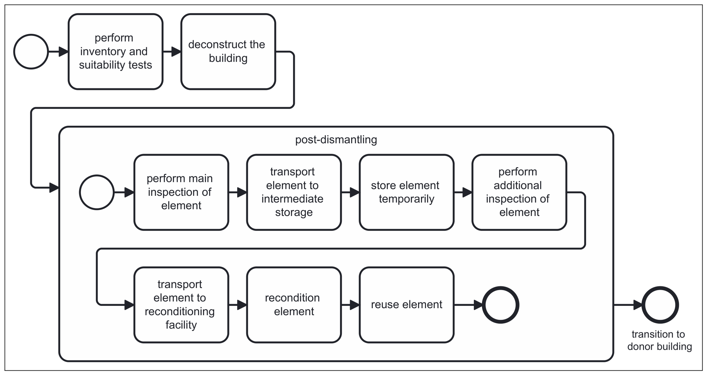
Figure A2.
Diagram formalised based on Guerriero et al. [28].
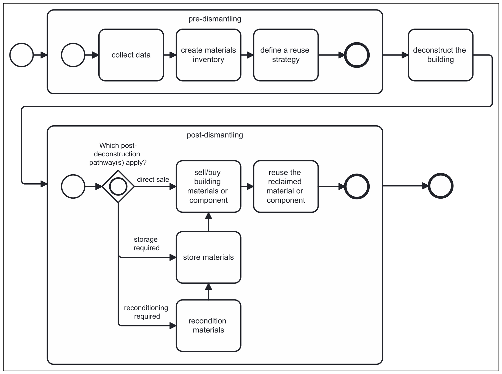
Figure A3.
Diagram formalised based on Thakuri et al. [54].
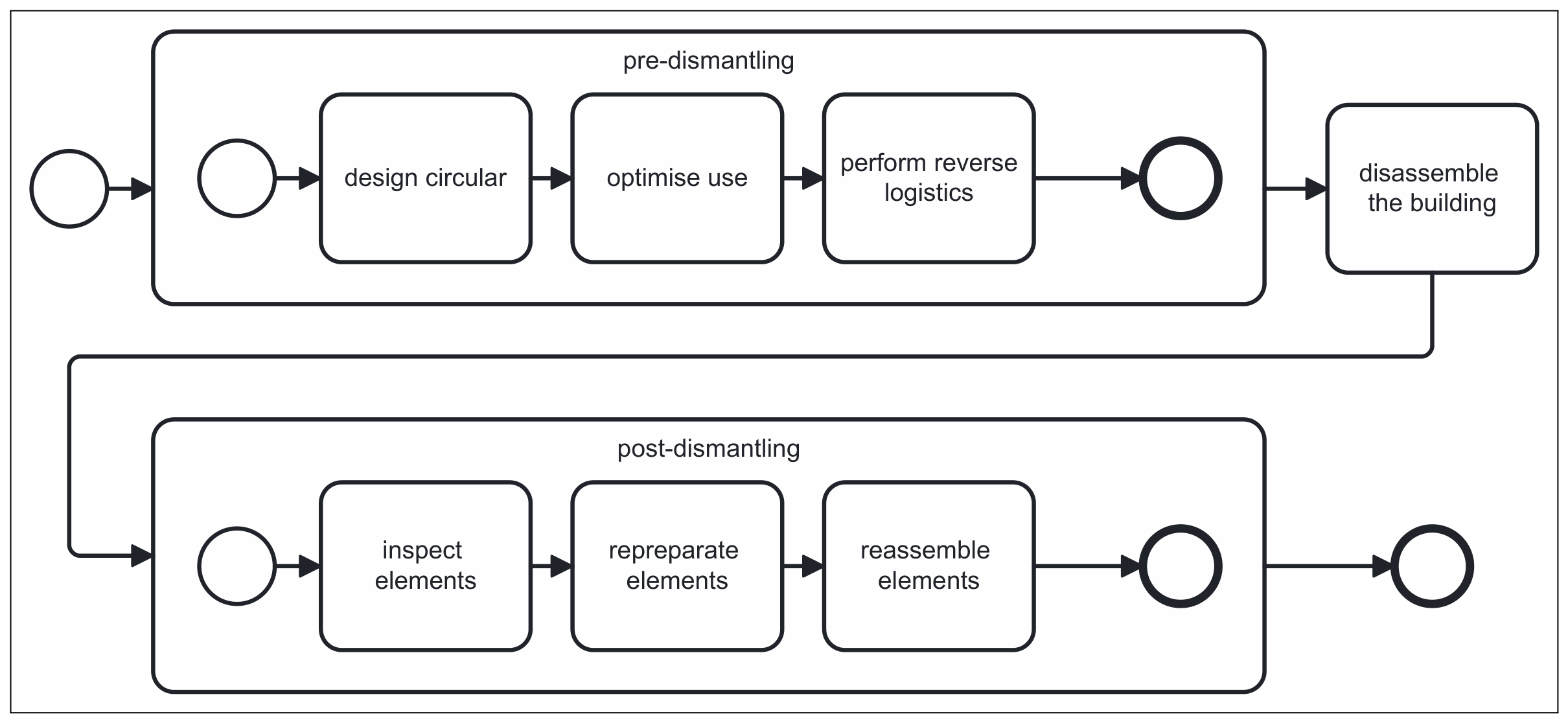
Figure A4.
Diagram formalised based on Küpfer et al. [21].
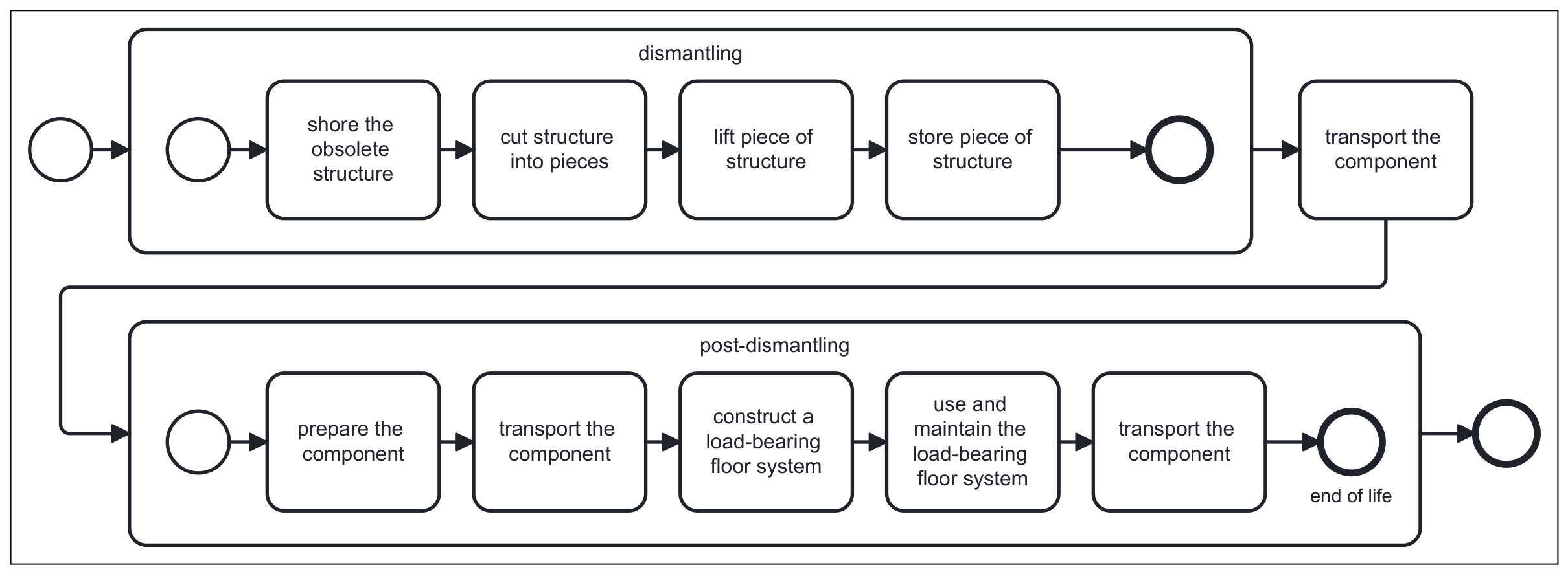
Figure A5.
Diagram formalised based on Mecka et al. [55].
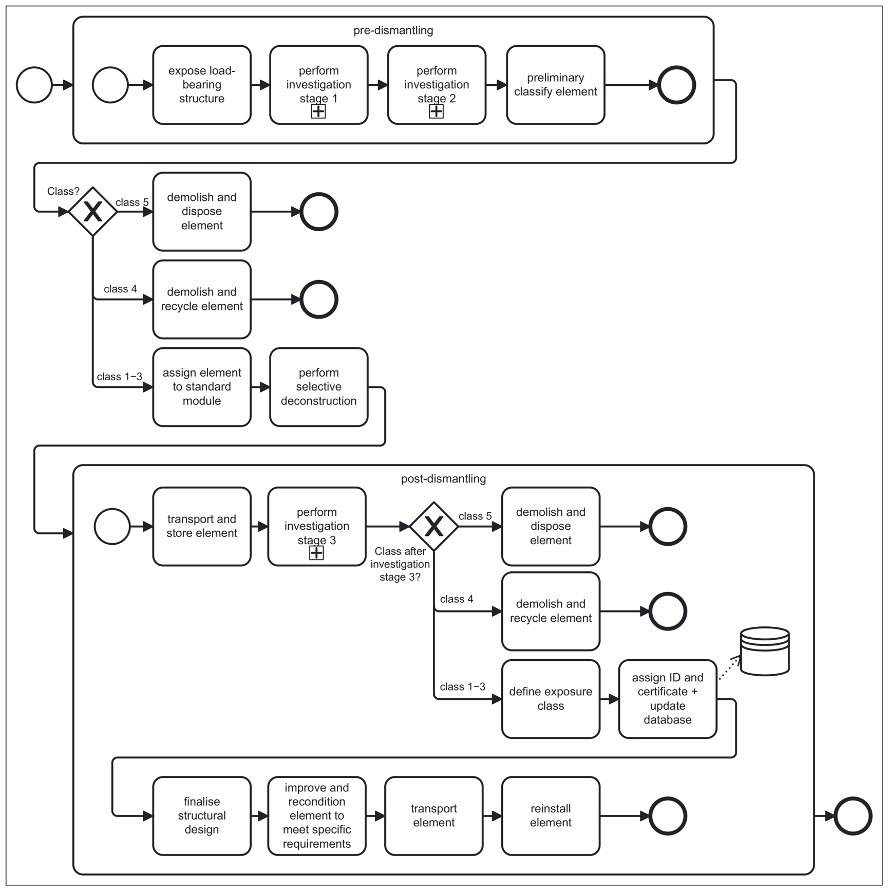
Figure A6.
Diagram formalised based on Devènes et al. [13].
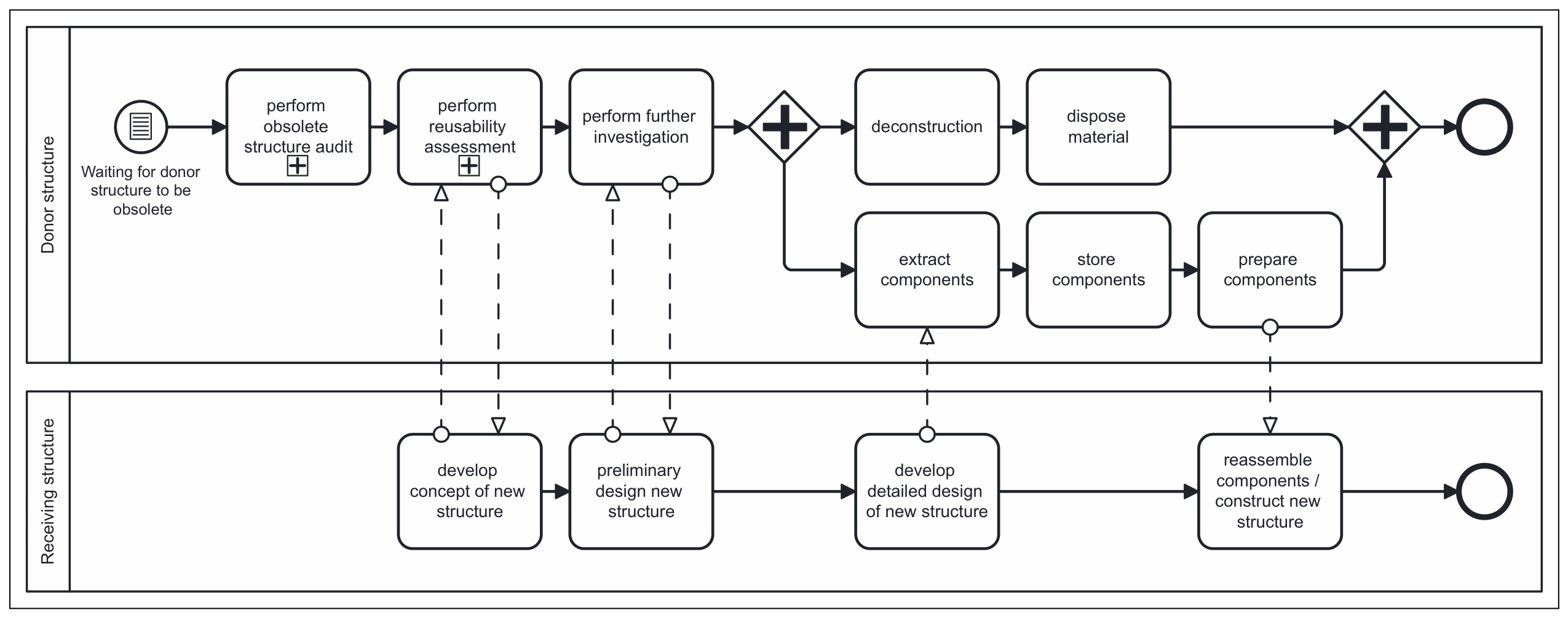
Figure A7.
Diagram formalised based on Dietsch et al. [18].
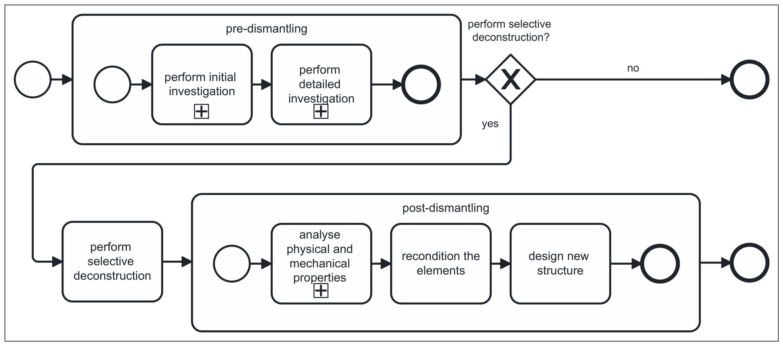
Appendix B. Activities for Concrete Element Reuse Identified in the Literature
Table A1.
Activities for concrete element reuse identified in the literature, grouped by process phase. Tasks are marked according to their assignment to activity categories (*1–*9): *1 Source building assessment; *2 Element inspection before dismantling *3 Dismantling; *4 Transportation; *5 Storage; *6 Element inspection after dismantling; *7 Processing; *8 Reinstallation; *9 Target building design.
References
- Li, C.; Pradhan, P.; Chen, G.; Kropp, J.P.; Schellnhuber, H.J. Carbon footprint of the construction sector is projected to double by 2050 globally. Commun. Earth Environ. 2025, 6, 831. [Google Scholar] [CrossRef] [Scilit] [PubMed]
- Moschen-Schimek, J.; Kasper, T.; Huber-Humer, M. Critical review of the recovery rates of construction and demolition waste in the European Union—An analysis of influencing factors in selected EU countries. Waste Manag. 2023, 167, 150–164. [Google Scholar] [CrossRef] [Scilit] [PubMed]
- German Federal Statistical Office (Destatis). Waste Generation in Germany Continued to Decline in 2023: −4.8% Compared to the Previous Year. Press Release No. 190. 2025. Available online: https://www.destatis.de/DE/Presse/Pressemitteilungen/2025/06/PD25_190_321.html (accessed on 13 April 2026). (In German)
- Gagg, C.R. Cement and concrete as an engineering material: An historic appraisal and case study analysis. Eng. Fail. Anal. 2014, 40, 114–140. [Google Scholar] [CrossRef] [Scilit]
- Association of German Engineers (VDI). Cement—How Far the Climate Killer Has Come on the Path to Becoming Environmentally Friendly. 2023. Available online: https://www.vdi.de/news/detail/zement-so-weit-ist-der-klimakiller-auf-dem-umweltfreundlichen-weg (accessed on 13 April 2026). (In German)
- Global Cement and Concrete Association (GCCA). Cement Industry Net Zero Progress Report 2024/25. 2025. Available online: https://gccassociation.org/cement-and-concrete-industry-net-zero-action-and-progress-report/ (accessed on 11 June 2026).
- Zabek, M.; Jegen, P.; Kreiss, L. Introducing a novel concept for an integrated demolition waste recycling center and the establishment of a stakeholder network: A case study from Germany. Sustainability 2024, 16, 3916. [Google Scholar] [CrossRef] [Scilit]
- Rockström, J.; Gaffney, O.; Rogelj, J.; Meinshausen, M.; Nakicenovic, N.; Schellnhuber, H.J. A roadmap for rapid decarbonization. Science 2017, 355, 1269–1271. [Google Scholar] [CrossRef] [Scilit] [PubMed]
- European Commission, Directorate-General for Environment. Waste Framework Directive. Available online: https://environment.ec.europa.eu/topics/waste-and-recycling/waste-framework-directive_en (accessed on 13 April 2026).
- German Federal Ministry for the Environment, Climate Action, Nature Conservation and Nuclear Safety. German Resource Efficiency Programme III: 2020–2023. Programme for the Sustainable Use and Protection of Natural Resources. 2020. Available online: https://www.bundesumweltministerium.de/fileadmin/Daten_BMU/Download_PDF/Ressourceneffizienz/progress_iii_programm_bf.pdf (accessed on 13 April 2026).
- Schinke, R.; Hennersdorf, J.; Gruhler, K.; Grießbach, U.; Schiller, G.; Leibniz Institute of Ecological Urban Regional Development. Material cadastre of buildings in Germany 2022 (matcad2022, adm2022). ioerDATA 2025. [Google Scholar] [CrossRef]
- German Federal Statistical Office (Destatis). Less Demolition: In 2022, Fewer Dwellings Were Removed from the Housing Stock than ever Before Since 1992, 2023. Press Release No. N050. 7 September 2023. Available online: https://www.destatis.de/DE/Presse/Pressemitteilungen/2023/09/PD23_N050_311.html (accessed on 13 April 2026). (In German)
- Devènes, J.; Bastien-Masse, M.; Fivet, C. Reusability assessment of reinforced concrete components prior to deconstruction from obsolete buildings. J. Build. Eng. 2024, 84, 108584. [Google Scholar] [CrossRef] [Scilit]
- Hossain, M.U.; Ng, S.T.; Antwi-Afari, P.; Amor, B. Circular economy and the construction industry: Existing trends, challenges and prospective framework for sustainable construction. Renew. Sustain. Energy Rev. 2020, 130, 109948. [Google Scholar] [CrossRef] [Scilit]
- Rakhshan, K.; Morel, J.C.; Alaka, H.; Charef, R. Components reuse in the building sector—A systematic review. Waste Manag. Res. 2020, 38, 347–370. [Google Scholar] [CrossRef] [Scilit] [PubMed]
- Schönfelder, L.; Byers, B.S.; Meliha, H.; De Wolf, C. A steel element reuse ontology for building audits in circular construction. Dev. Built Environ. 2025, 21, 100638. [Google Scholar] [CrossRef] [Scilit]
- Ruda, C.; Saadé, M.; Sorin, E.; Douthe, C.; Lecompte, F.; Baverel, O. A methodology for stock assessment and traceability at the component level: The case of structural steel reuse. J. Phys. Conf. Ser. 2025, 3140, 162013. [Google Scholar] [CrossRef] [Scilit]
- Dietsch, P.; Ummenhofer, T.; Frese, M.; Müller, M.; Winter, S.; Mensinger, M.; Ehrenlechner, C. Guideline for the Reuse of Load-Bearing Structural Components (Published in German as: Leitfaden zur Wiederverwendung Tragender Bauteile). 2025. Available online: https://mlw.baden-wuerttemberg.de/de/service/publikation/did/leitfaden-zur-wiederverwendung-tragender-bauteile-stahl-und-holzbau (accessed on 13 April 2026).
- Kręt-Grześkowiak, A.; Bruhn, S.; Jensen, A.A.V.; Birkved, M. Quantifying the environmental impact of structural timber across multiple future lifecycles. Discov. Appl. Sci. 2024, 6, 197. [Google Scholar] [CrossRef] [Scilit]
- Stenberg, E.; Vargas Hernández, J.; Huuhka, S. ReCreate: Deconstruction and reuse instead of demolition and waste. ARQ 2022, 112, 84–95. [Google Scholar] [CrossRef] [Scilit]
- Küpfer, C.; Bertola, N.; Fivet, C. Reuse of cut concrete slabs in new buildings for circular ultra-low-carbon floor designs. J. Clean. Prod. 2024, 448, 141566. [Google Scholar] [CrossRef] [Scilit]
- Association of Ready-Mixed Concrete Germany. Yearly Report 2025. 2025. Available online: https://www.transportbeton.org/fileadmin/media/Wir/Verband/PDF/Jahresbericht_BTB_2025_online.pdf (accessed on 13 April 2026). (In German)
- ISO/IEC 19510:2013; Information Technology: Object Management Group Business Process Model and Notation. ISO/IEC: Geneva, Switzerland, 2013.
- Suchorzewski, J.; Santandrea, F.; Malaga, K. Reusing of concrete building elements—Assessment and quality assurance for service-life. Mater. Today Proc. 2026, 121, 345–350. [Google Scholar] [CrossRef] [Scilit]
- Dervishaj, A.; Räsänen, A.; Gudmundsson, K.; Lahdensivu, J. From durability to circularity: Ensuring service life and enabling reuse of concrete in circular construction. Mater. Struct. 2026, 59, 28. [Google Scholar] [CrossRef] [Scilit]
- Bertino, G.; Kisser, J.; Zeilinger, J.; Langergraber, G.; Fischer, T.; Österreicher, D. Fundamentals of building deconstruction as a circular economy strategy for the reuse of construction materials. Appl. Sci. 2021, 11, 939. [Google Scholar] [CrossRef] [Scilit]
- Salama, W. Design of concrete buildings for disassembly: An explorative review. Int. J. Sustain. Built Environ. 2017, 6, 617–635. [Google Scholar] [CrossRef] [Scilit]
- Guerriero, A.; Durmisevic, E.; Boje, C.; Mack, N. Digitalising the deconstruction process. In Circular Economy for the Built Environment; Charef, R., Ed.; Routledge: London, UK, 2024; pp. 201–230. [Google Scholar] [CrossRef] [Scilit]
- Häußler, M.; Esser, S.; Borrmann, A. Code compliance checking of railway designs by integrating BIM, BPMN and DMN. Autom. Constr. 2021, 121, 103427. [Google Scholar] [CrossRef] [Scilit]
- Ye, X.; Zeng, N.; Tao, X.; Han, D.; König, M. Smart contract generation and visualization for construction business process collaboration and automation: Upgraded workflow engine. J. Comput. Civ. Eng. 2024, 38, 04024030. [Google Scholar] [CrossRef] [Scilit]
- Ali, A.K.; Badinelli, R. Novel integration of sustainable and construction decisions into the design bid build project delivery method using BPMN. Procedia Eng. 2016, 145, 164–171. [Google Scholar] [CrossRef] [Scilit]
- Ding, L.; Wang, T.; Gielingh, W.; Chan, P. Development of a process model-based tool for circular construction supply chain integration. In Proceedings of the 2024 European Conference on Computing in Construction; European Council on Computing in Construction (EC3): Sint-Niklaas, Belgium, 2024; pp. 790–797. [Google Scholar] [CrossRef] [Scilit]
- Boley, H.; Chang, E. Digital ecosystems: Principles and semantics. In Proceedings of the 2007 Inaugural IEEE-IES Digital EcoSystems and Technologies Conference; IEEE: Piscataway, NJ, USA, 2007; pp. 398–403. [Google Scholar] [CrossRef] [Scilit]
- Li, W.; Badr, Y.; Biennier, F. Digital ecosystems: Challenges and prospects. In Proceedings of the International Conference on Management of Emergent Digital EcoSystems (MEDES’11); Association for Computing Machinery (ACM): New York, NY, USA, 2011; pp. 117–122. [Google Scholar] [CrossRef] [Scilit]
- Briscoe, G.; De Wilde, P. Digital ecosystems: Evolving service-orientated architectures. In Proceedings of the 1st International Conference on Bio Inspired Models of Network, Information and Computing Systems; ACM: New York, NY, USA, 2006; pp. 17–22. [Google Scholar] [CrossRef] [Scilit]
- Briscoe, G.; Sadedin, S.; de Wilde, P. Digital ecosystems: Ecosystem-oriented architectures. Nat. Comput. 2011, 10, 1143–1194. [Google Scholar] [CrossRef] [Scilit]
- Kovacic, I.; Honic, M.; Sreckovic, M. Digital platform for circular economy in AEC industry. Eng. Proj. Organ. J. 2020, 9, 16. [Google Scholar] [CrossRef] [Scilit]
- Sakthibala, R.K.; Vasanthi, P.; Hariharasudhan, C.; Partheeban, P. A critical review on recycling and reuse of construction and demolition waste materials. Clean. Waste Syst. 2025, 12, 100375. [Google Scholar] [CrossRef] [Scilit]
- Ostapska, K.; Hingorani, R.; Tecław, W.; Kaufmann, F.; Gradeci, K.; Rüther, P. Automated robotic deconstruction sequence planning from scan-to-BIM data for reinforced concrete structure reuse. Autom. Constr. 2025, 180, 106548. [Google Scholar] [CrossRef] [Scilit]
- Boje, C.; Guerriero, A.; Kubicki, S.; Rezgui, Y. Towards a semantic construction digital twin: Directions for future research. Autom. Constr. 2020, 114, 103179. [Google Scholar] [CrossRef] [Scilit]
- Zielonka, H.; Sanio, D.; Kannenberg, F.; Al-Shboul, O.; Ringeloth, D.; Bogojevic, A.; Ahmed, R.S.; Dollendorf, M.; Abdelazziz, Y.; Roumia, N.; et al. Modular reuse of existing load-bearing structures: From concept to full-scale demonstration. Beton Stahlbetonbau 2026, 121. [Google Scholar] [CrossRef] [Scilit]
- Kromoser, B.; Gappmaier, P.; Ahmed, I.; Reichenbach, S. Circular economy in concrete construction through modular construction, automated design and production of structurally optimised reusable concrete building components. Case Stud. Constr. Mater. 2025, 23, e05139. [Google Scholar] [CrossRef] [Scilit]
- Zou, Y.; Ren, Z.; Wang, L.; Lei, Q.; Li, X.; Liang, T.; Chen, W. A BIM-based workflow for early-stage embodied carbon assessment using reusable assembly templates and rule-based mapping. Buildings 2026, 16, 710. [Google Scholar] [CrossRef] [Scilit]
- Dervishaj, A.; Malmqvist, T.; Silfwerbrand, J.; Gudmundsson, K. A digital workflow for assessing lifespan, carbonation, and embodied carbon of reusing concrete in buildings. J. Build. Eng. 2024, 96, 110536. [Google Scholar] [CrossRef] [Scilit]
- Heuer, C.; Jung, V.; Kamp, C.; Brell-Cokcan, S. Deconstruction system for the reuse of concrete building parts in circular automated construction. J. Build. Eng. 2025, 114, 113952. [Google Scholar] [CrossRef] [Scilit]
- Caldera, S.; Ryley, T.; Zatyko, N. Enablers and barriers for creating a marketplace for construction and demolition waste: A systematic literature review. Sustainability 2020, 12, 9931. [Google Scholar] [CrossRef] [Scilit]
- Qazi, Z.; Wuni, I.Y.; Akinkuowo, F. Material passports for circular economy in the construction industry: State-of-art-review. Int. J. Constr. Manag. 2026, 1–20. [Google Scholar] [CrossRef] [Scilit]
- Teuffel, P.; Schulz, M. ReCreate: Technical and organisational framework conditions for a circular concrete value chain. Bautechnik 2026, 103, 344–350. [Google Scholar] [CrossRef] [Scilit]
- Küpfer, C.; Bastien-Masse, M.; Devènes, J.; Fivet, C. Environmental and economic analysis of new construction techniques reusing existing concrete elements: Two case studies. IOP Conf. Ser. Earth Environ. Sci. 2022, 1078, 012013. [Google Scholar] [CrossRef] [Scilit]
- Eschenbach, M.B.; Wagner, A.K.; Ledderose, L.; Böhret, T.; Wohlfeld, D.; Gille-Sepehri, M.; Kuhn, C.; Kloft, H.; Tessmann, O. Matter as met: Towards a computational workflow for architectural design with reused concrete components. In Proceedings of the Towards Radical Regeneration; Springer International Publishing: Cham, Switzerland, 2023; pp. 442–455. [Google Scholar] [CrossRef] [Scilit]
- Harsunen, P.; Uotila, U.; Joensuu, T.; Saari, A. Deconstruction of a prefabricated concrete building designed for disassembly–cost comparison of deconstruction and demolition. Environ. Res. Infrastruct. Sustain. 2025, 5, 025005. [Google Scholar] [CrossRef] [Scilit]
- Munaro, M.R.; Tavares, S.F. Design for adaptability and disassembly: Guidelines for building deconstruction. Constr. Innov. 2023, 25, 665–687. [Google Scholar] [CrossRef] [Scilit]
- Repousis, N.; Rausch, C. Systematic review of engineering procedures to facilitate decision-making for concrete element reuse. J. Archit. Eng. 2025, 31, 03125004. [Google Scholar] [CrossRef] [Scilit]
- Thakuri, P.K.; Alkki, L.; Aarikka-Stenroos, L. Digital technologies enabling component reuse in circular value chains: Using digital twin, Internet of Things and robots in construction and manufacturing sectors. R&D Manag. 2025, 55, 1161–1216. [Google Scholar] [CrossRef] [Scilit]
- Mecka, R.; Geng, J.; Schubert, A.; Bos, F.P.; Nübel, K.; Fischer, O. A framework for the reuse of reinforced concrete elements. Beton Stahlbetonbau 2025, 120, 785–797. [Google Scholar] [CrossRef] [Scilit]
- Hagedorn, P.; Krautgartner, N.; Günther, F.; Kannenberg, F.; Schürmann, A.; Abdelazziz, Y.; Al-Shboul, O.; Curoșu, I.; Thewes, M.; Menges, A.; et al. Linking design, deconstruction and characterization: A digital ecosystem for sustainable reuse of cast-in-place concrete elements. Beton Stahlbetonbau 2026, 121. [Google Scholar] [CrossRef] [Scilit]
- Devènes, J.; Bastien-Masse, M.; Fivet, C. Factsheet template for reinforced concrete components—Obsolete structure audit. Zenodo 2023. [Google Scholar] [CrossRef]
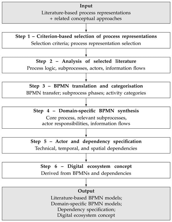
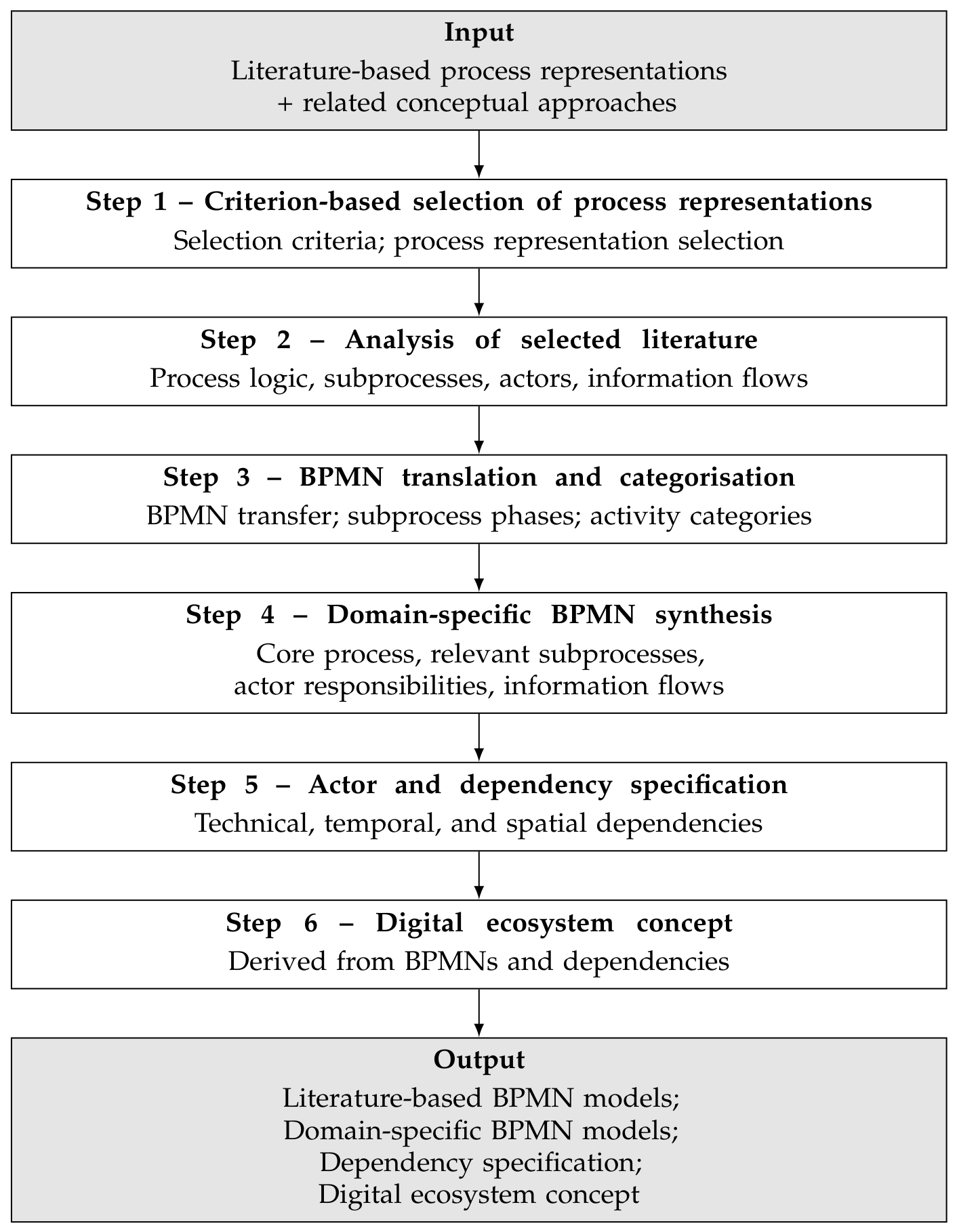
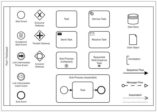
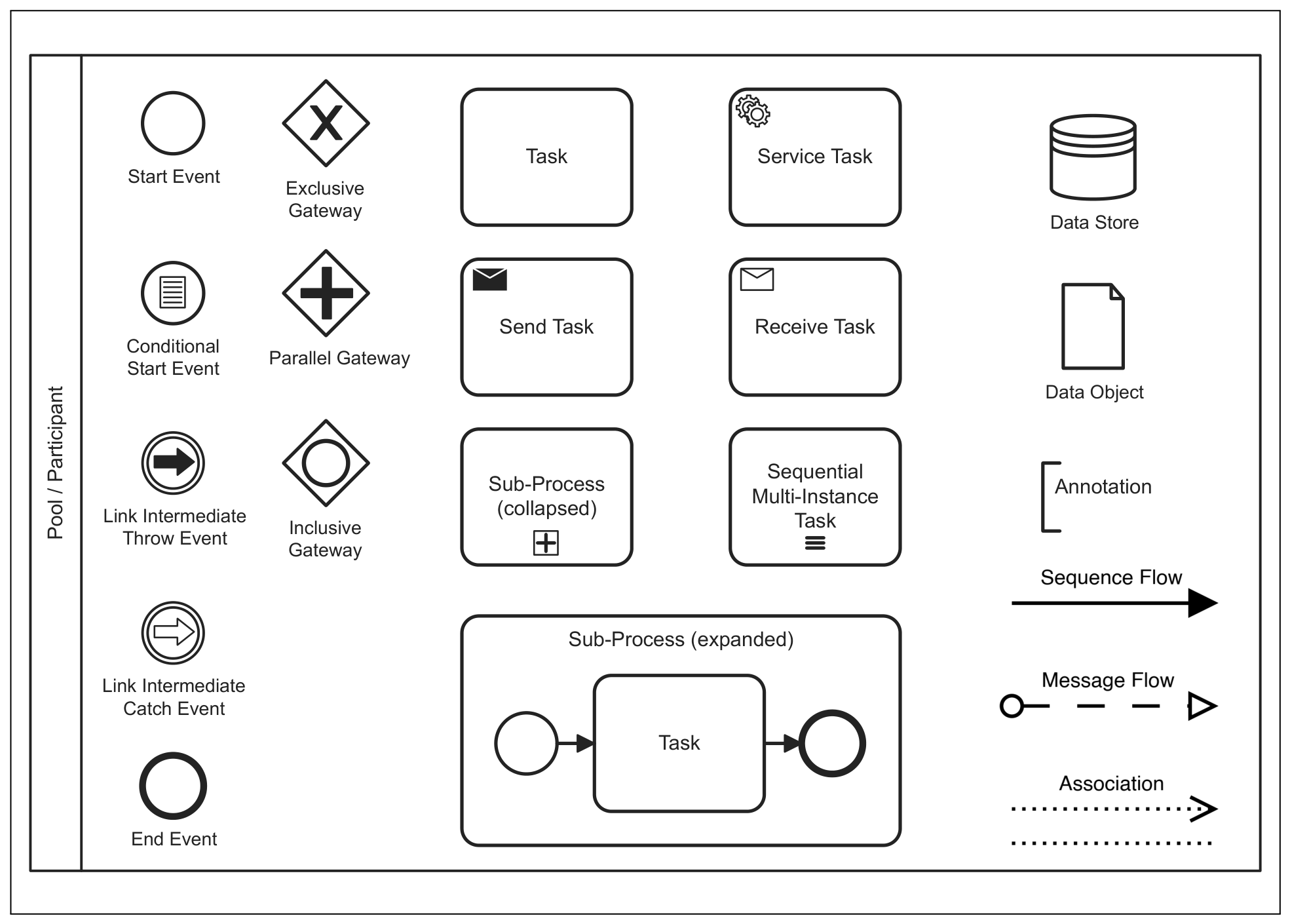
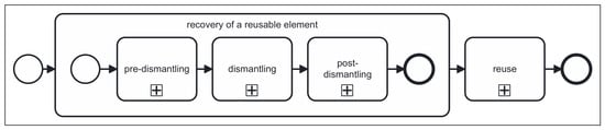
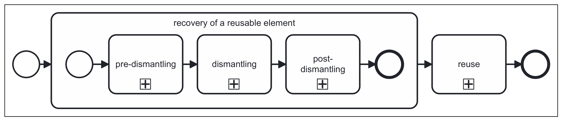
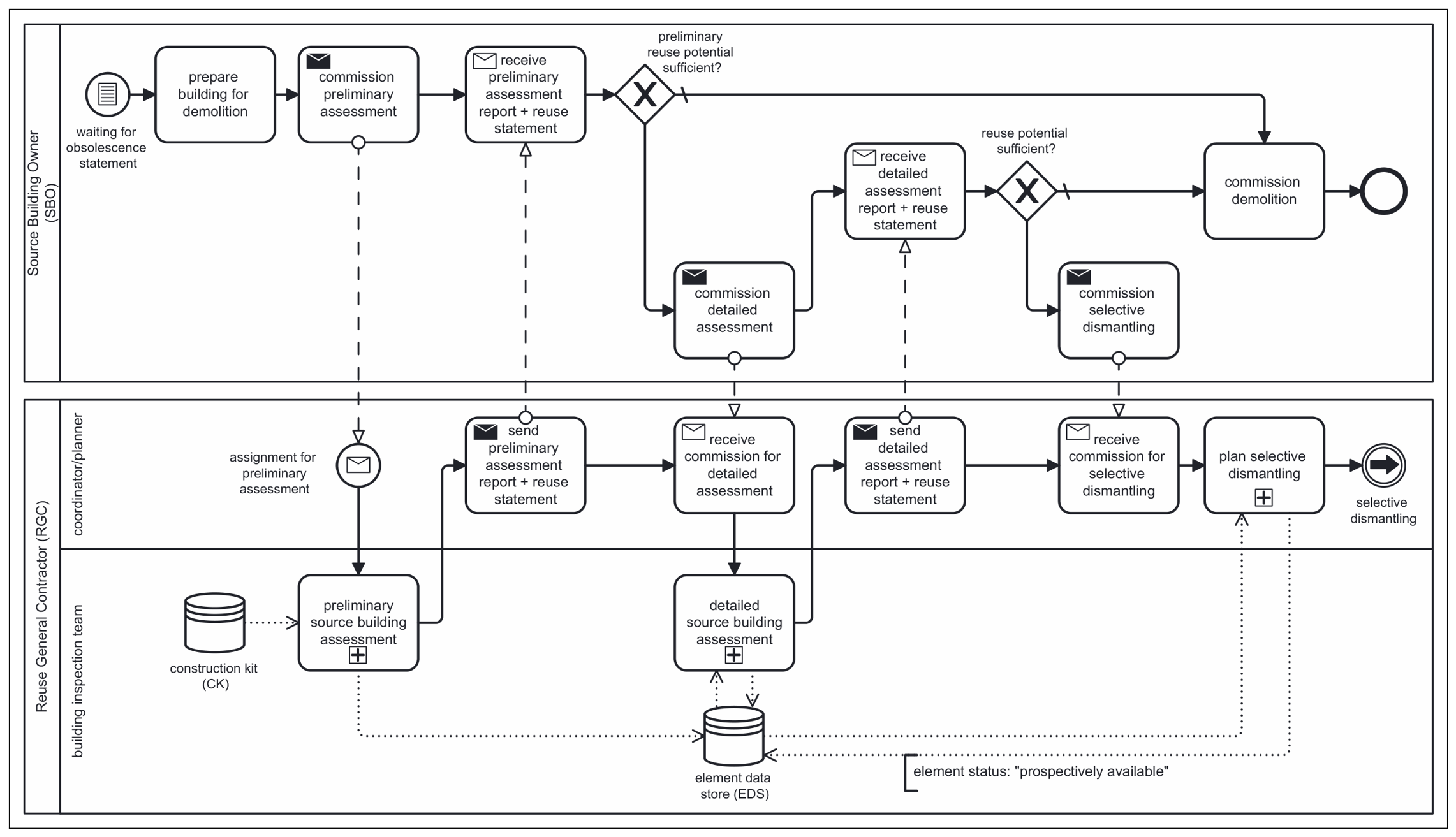
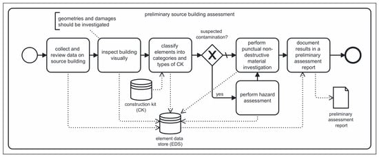
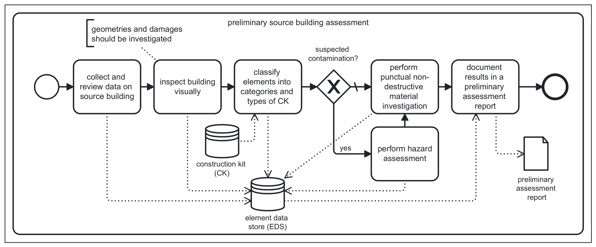
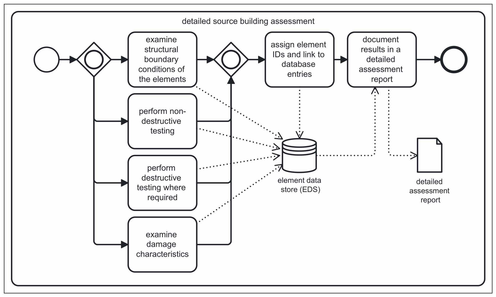
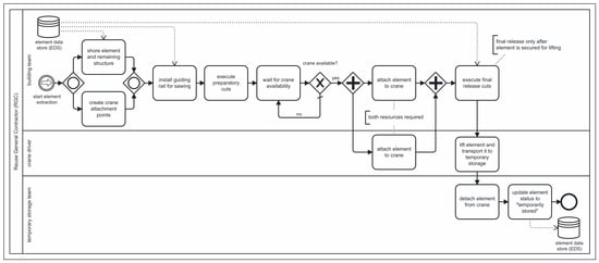
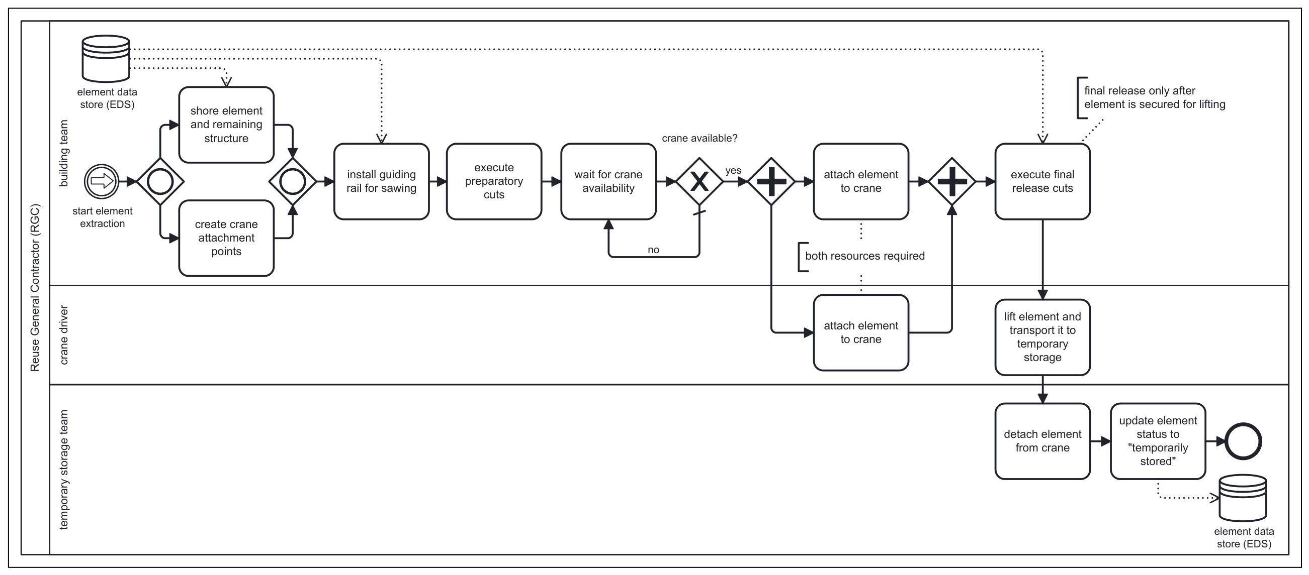
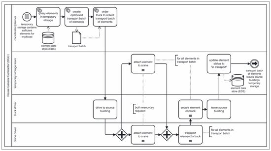
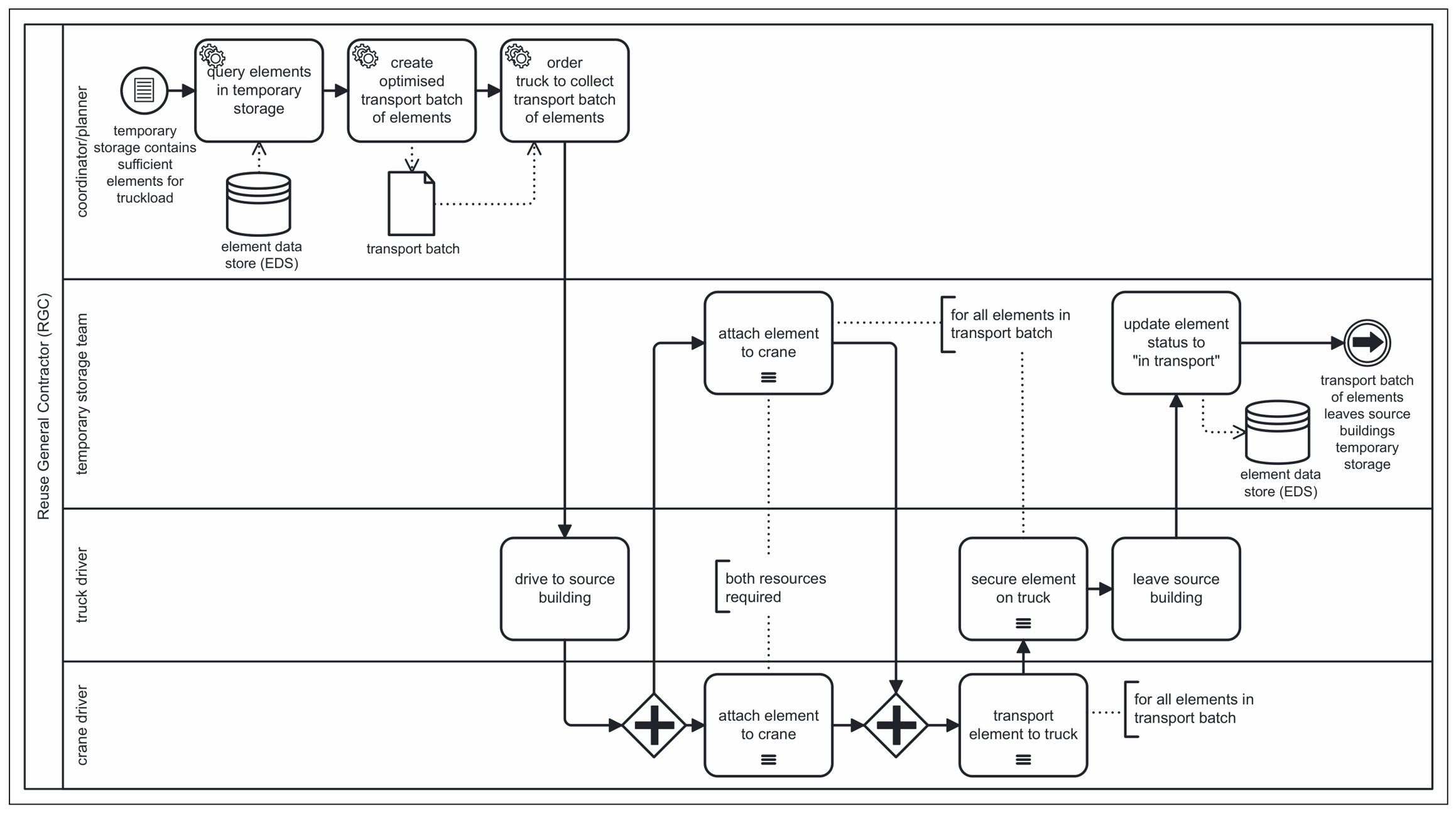
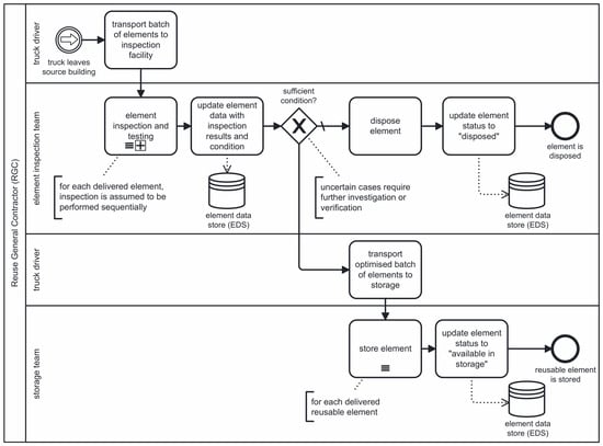
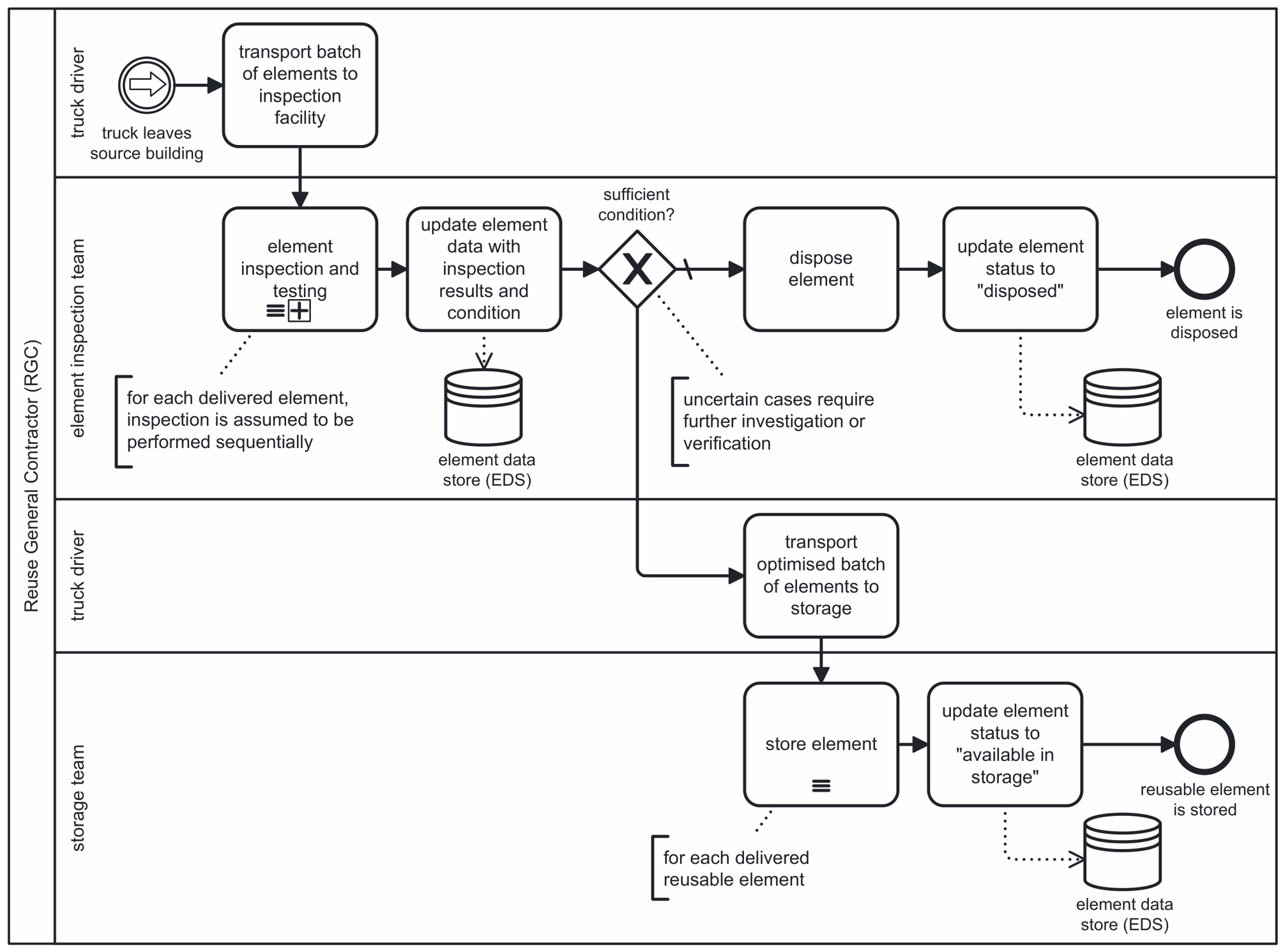
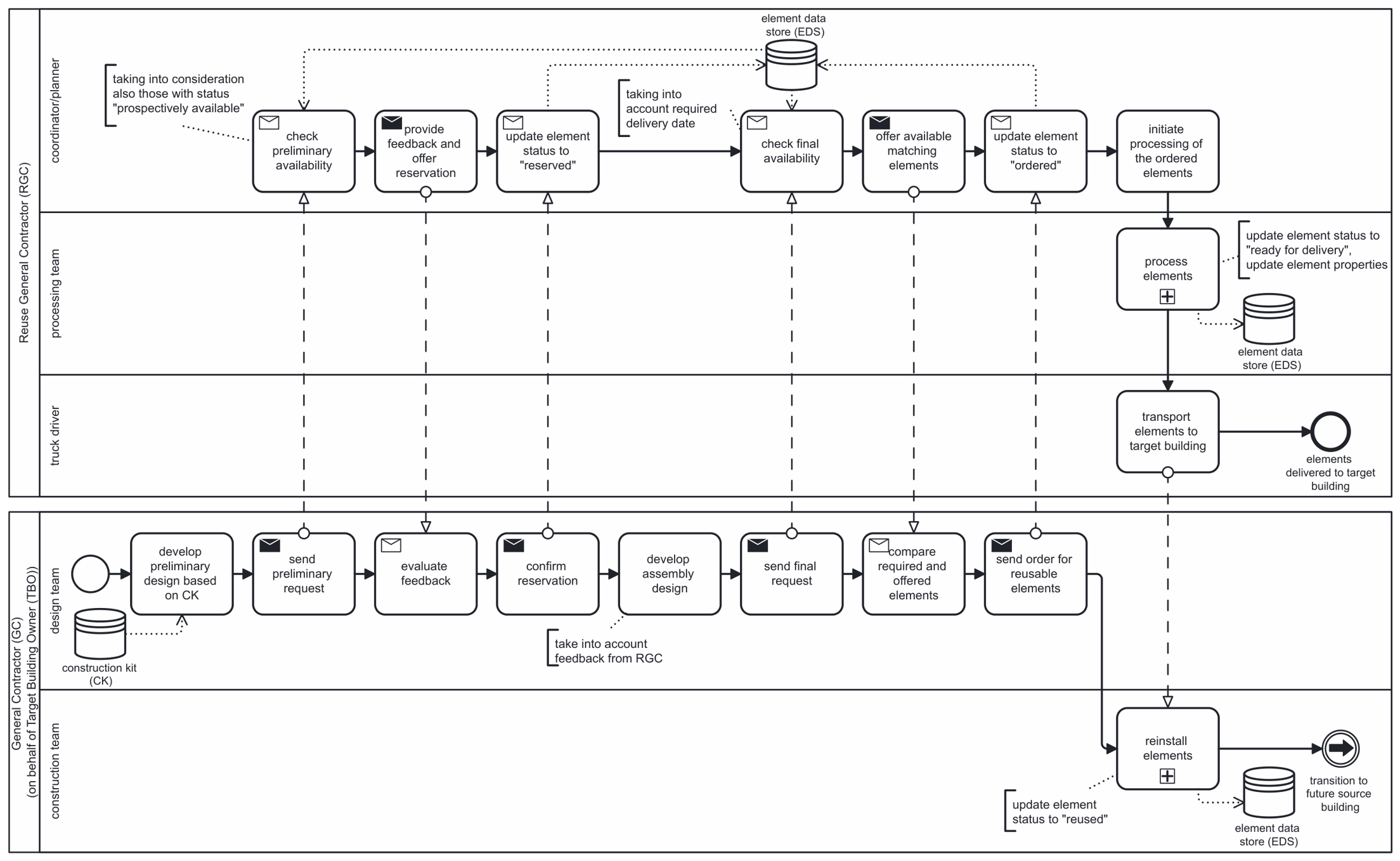
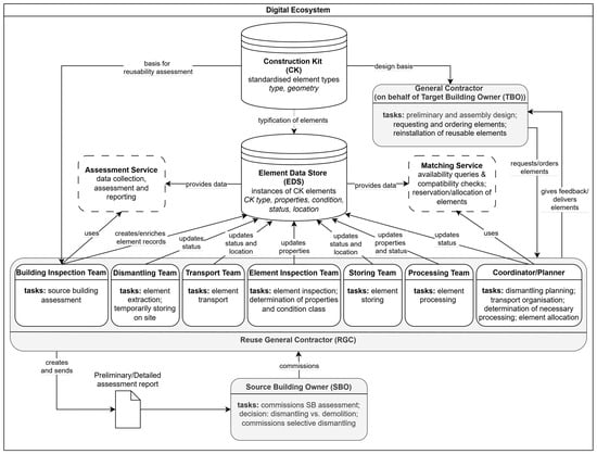
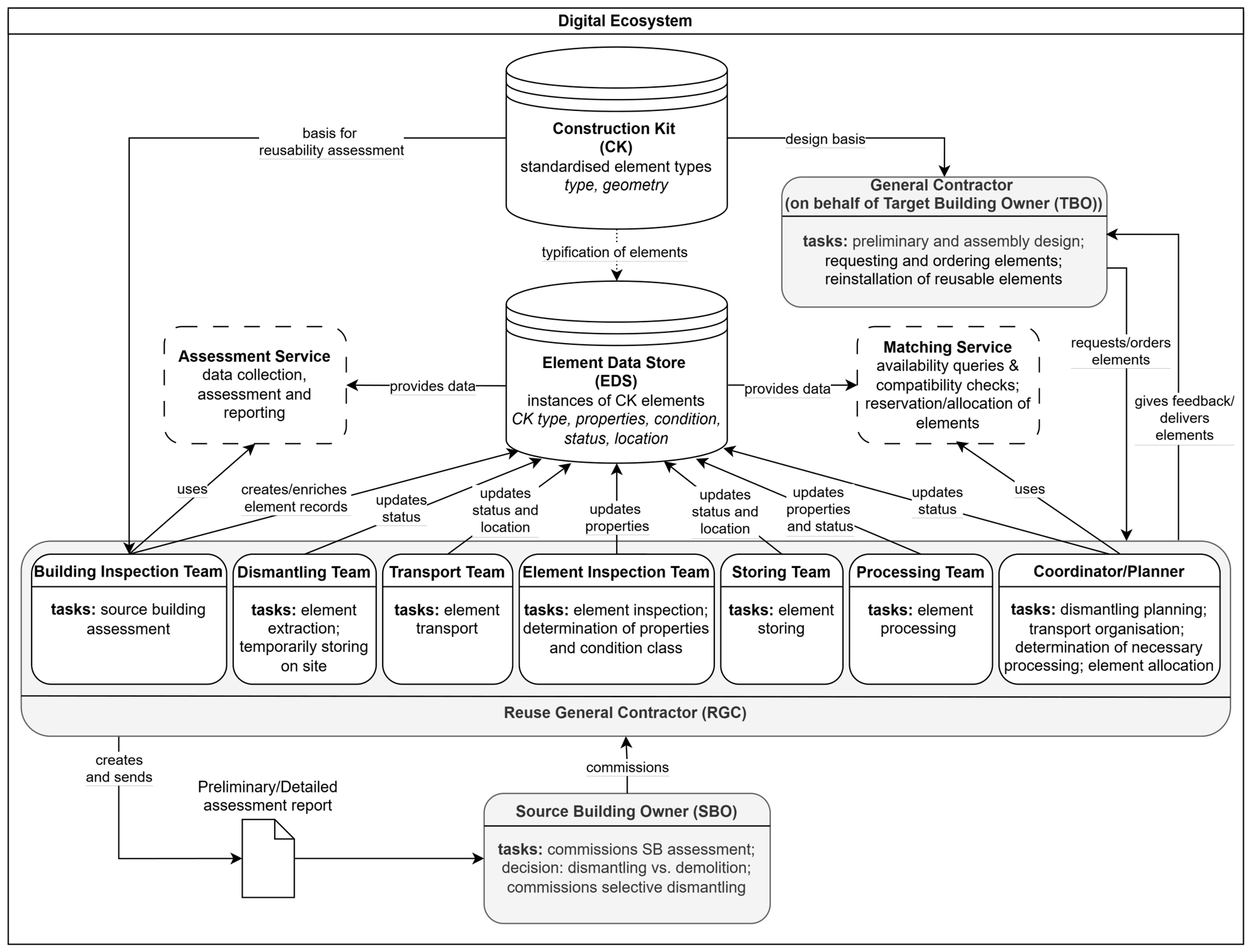

Disclaimer/Publisher’s Note: The statements, opinions and data contained in all publications are solely those of the individual author(s) and contributor(s) and not of MDPI and/or the editor(s). MDPI and/or the editor(s) disclaim responsibility for any injury to people or property resulting from any ideas, methods, instructions or products referred to in the content. |
© 2026 by the authors. Licensee MDPI, Basel, Switzerland. This article is an open access article distributed under the terms and conditions of the Creative Commons Attribution (CC BY) license.