1. Introduction
1.1. Background
Sustainable concrete infrastructure relies on the early identification of deterioration processes, allowing for their management with minimal material, energy, and economic expenditure. Non-destructive testing contributes to this objective by providing continuous and repeatable measurements that characterize chloride and sulfate-induced damage without disturbing the structural system. These techniques support rational maintenance planning by quantifying deterioration progression, allowing interventions that preserve existing structural elements rather than replace them. Reducing premature reconstruction, limiting intrusive inspection, and extending service life all contribute to lower emissions and reduced consumption of natural resources associated with concrete production and repair activities. By linking deterioration mechanisms with reliable diagnostic tools, this review emphasizes how NDT enables more durable and resource-efficient management of reinforced concrete exposed to aggressive environments.
Reinforced concrete is one of the most widely used construction materials globally [
1]. Due to this, protecting the structural integrity of reinforced concrete is crucial. Ion attacks, most commonly chloride and sulfate attacks, cause damage by weakening the steel reinforcement and degrading the concrete itself. This deterioration increases maintenance costs and reduces the service life of structures [
2]. Therefore, detecting ion attacks is an important step in ensuring the long-term performance of reinforced concrete and preventing premature failure. Several research models have been developed to predict the ingress of chloride and sulfate ions [
3,
4]. These models are useful for estimating the expected service life of concrete structures; however, they cannot replace direct methods for identifying locations of ion attack. A sound understanding of the mechanisms of chloride and sulfate ion attacks is necessary to assess the effectiveness of available testing methods for detecting deterioration in reinforced concrete.
The two types of ion attacks occur through different chemical processes. Chloride ion attacks result from reactions between chloride ions and the embedded steel reinforcement [
5]. This reaction causes corrosion of the steel, resulting in a reduction in its structural strength. Sulfate ion attacks occur when sulfate solutions react with the hydrated compounds in cement paste, forming ettringite, gypsum, and other expansive minerals [
6]. The formation of these compounds increases the concrete’s volume, leading to cracking and deformation within the structure [
7].
Both non-destructive testing (NDT) and destructive testing (DT) methods can be used to evaluate reinforced concrete for evidence of ion-induced deterioration. Comparative studies have shown that NDT is preferable for in situ evaluation because it causes little to no damage to the structure while providing data comparable to those obtained from DT results [
8,
9,
10,
11]. As a result, NDT is now the preferred approach for evaluating reinforced concrete. Common NDT methods for detecting ion attacks include electrical resistivity (ER), acoustic emission (AE), infrared thermography (IRT), and ground-penetrating radar (GPR). These techniques employ various physical principles to assess, either directly or indirectly, the presence of destructive ions within concrete and around the steel reinforcement.
1.2. Review Objectives
The objective of this study is to evaluate the current use of non-destructive testing (NDT) for assessing deterioration caused by chloride and sulfate ion attacks in reinforced concrete and to examine how these methods support the development of durable and sustainable concrete infrastructure. The review analyzes the mechanisms of ion ingress, the associated degradation processes, and the NDT techniques used to detect and characterize their effects. It also synthesizes findings from case studies and field applications to illustrate the practical value of NDT in monitoring deterioration while minimizing material consumption and intrusive investigation. Additionally, the limitations of existing methods and recent advancements that have enhanced diagnostic accuracy are examined. Through the analysis of current research, this review identifies the most effective applications of NDT, highlights existing knowledge gaps, and clarifies the role of NDT in supporting long-term performance, maintenance efficiency, and sustainability in reinforced concrete structures exposed to aggressive environments.
2. Ion Attack Mechanisms in Reinforced Concrete
2.1. The Challenge of Ion Penetration
Ion attacks in reinforced concrete occur through the penetration of ion-carrying substances into the pore structure of the concrete [
12,
13]. The ingress of chloride and sulfate ions, combined with the presence of oxygen, initiates chemical reactions that corrode the steel reinforcement and deteriorate the surrounding concrete. Corrosion of the embedded steel reduces shear-tensile strength, shear-compressive strength, and overall ductility [
14]. Similarly, sulfate-induced degradation weakens the concrete matrix through the formation of micro-cracks, gypsum, and ettringite, which cause harmful expansion and loss of structural integrity [
15].
2.2. Overview of Chloride Ion Attacks
Chloride-induced corrosion occurs when chloride ions penetrate reinforced concrete. This penetration can take place at joints, through cracks, or via the pore network of the concrete [
16]. In addition to these entry pathways, several mechanisms govern the transport of chloride ions within concrete. These include diffusion driven by concentration gradients, absorption through capillary action, migration under an electrical field, pressure-induced flow, and wicking, which occurs when water absorption and vapor diffusion act together [
17].
2.2.1. Diffusion Model
Diffusion is the most common transport mechanism observed in conventional concrete structures. It refers to the movement of ions from regions of higher concentration to regions of lower concentration. The diffusion of chloride ions within concrete is typically modeled using the error function solution of Fick’s Second Law [
18], expressed as follows:
where D = diffusion coefficient (m
2/s); t = time of exposure (s); C(x, t) = chloride concentration at depth x after time t (%/m
3); Cs = surface chloride concentration (%/m
3); and erf is the error function. The diffusion profile can be calculated using Equation (1) when the concrete is homogeneous, D and Cs remain constant over time, and the chlorides do not react with the cement matrix, or when the chloride-binding ratio is constant.
2.2.2. Electrochemical Process of Corrosion
The corrosion of steel reinforcement in concrete is an electrochemical process consisting of both anodic and cathodic reactions [
19,
20]. The following reactions occur during corrosion:
The anodic reaction represents the dissolution of the steel surface, where corrosion leads to a reduction in the thickness of the reinforcement, typically measured as mass loss per unit time. The average rate of steel loss due to corrosion is approximately 0.25 g/m
2 per day.
Table 1 summarizes the conditions required to initiate and sustain the corrosion process [
19].
2.3. Overview of Sulfate Ion Attacks
Sulfate-induced deterioration occurs when sulfate ions react with the cementitious compounds in concrete. The transport of sulfate ions into the concrete is influenced by electrochemical potential gradients. Reactions between the sulfate ions and the cement paste lead to the formation of ettringite, gypsum, and other secondary mineral phases [
21]. The visible effects of this degradation include expansion, cracking, and spalling, all of which contribute to the progressive weakening of the structure.
2.3.1. Transportation Process
In saturated environments without pressure gradients, sulfate ions are transported from external sources into the cement paste by electrochemical potential gradients, which involve both electrical and chemical potentials [
21,
22]. The transfer of ions occurs from regions of high concentration to regions of lower concentration. Electrical potential gradients arise from the different migration rates of charged solutes present in the system.
Additional transport mechanisms can also occur in saturated environments. In non-isothermal systems, temperature gradients promote ion flux through the Soret effect (thermal diffusion). Chemical activity can further influence solvent interactions, especially when the ionic strength of the pore solution is high.
In non-saturated environments, ion transport occurs mainly through liquid movement from external sources into the concrete’s pore network. Sulfate-rich solutions are absorbed by capillary action when in contact with the concrete surface. Fick’s Second Law can be used to model the diffusion of sulfate ions and is expressed as follows [
21]:
where C is the concentration of sulfate ions per unit volume of concrete, x is the distance from the surface, t is the time, Deff is the effective diffusion coefficient of sulfate ions in concrete, k is the reaction rate between sulfate ions and cement hydration products, and U
CA is the concentration of calcium aluminates, defined by Equation (6). C
0C3A represents the initial content of C
3A in the concrete, b is the initial content of gypsum, and ha is the degree of cement hydration as a function of time s, defined by Equation (7).
2.3.2. Chemical Process of Sulfate Attack
The main products of sulfate attack on concrete are gypsum, ettringite, and sodium sulfate salts [
23]. The following chemical equations represent the primary reactions that occur during sulfate-induced erosion:
Subscripts (s), (aq), and (l) denote the solid state, the ionic state in solution, and the liquid state, respectively. The formation of gypsum, ettringite, and sulfate salts leads to expansion and progressive deterioration of the concrete matrix. A clear understanding of these chemical attack mechanisms is essential for improving the monitoring and detection of sulfate-induced damage in concrete structures.
2.4. Strategies for Mitigation and Application Instances
Because of the harmful effects of ion attacks on reinforced concrete, various strategies have been developed to enhance the service life of concrete and mitigate the negative impacts of chloride and sulfate ingress. Additives and admixtures have been tested and applied to reduce the transport of these ions within the concrete matrix. Calcium stearate has been used to modify the hydrophilicity of concrete, which resulted in reduced water absorption and lower chloride diffusion [
24]. It was determined that the optimum calcium stearate content was 4%. The use of limestone powder has also been investigated to improve resistance against both chloride and sulfate ion attacks [
25]. The study demonstrated that replacing up to 24% of the cement with limestone powder enhanced chloride and sulfate resistance, although the overall compressive strength decreased slightly. Silica fume has been implemented as a permeability-control agent [
26]. Results showed that silica fume reduced sulfate ingress by decreasing the permeability of concrete.
Penetration-resistant coatings have also been explored as a means of reducing ion attacks. Rubber, polyurethane, and silane-based coatings were applied to the surface of concrete samples to reduce the ingress of ion-transporting water [
27]. These coatings were initially effective but became less efficient after multiple freeze–thaw cycles.
Although these approaches help reduce the impact of destructive ions, their performance can be limited by environmental conditions and material aging. Therefore, the detection and monitoring of chloride and sulfate ions within reinforced concrete remains essential for long-term durability assessment.
3. Non-Destructive Testing Methods
3.1. Introduction to NDT Techniques
Non-Destructive Testing (NDT) refers to the identification of damage, irregularities, or other defects on the surface or within the interior of a material without altering or destroying it [
28]. Because NDT does not harm the tested material, it enables evaluation in its in-service condition. This makes NDT an essential tool for preventive maintenance and structural health monitoring. Many NDT techniques are currently applied to assess the condition and performance of various cementitious materials.
NDT plays a crucial role in evaluating reinforced concrete structures. Its application enables continuous monitoring and early detection of potential problems that may not be visible through conventional testing methods. NDT techniques help assess possible defects, internal conditions, and the overall structural integrity of reinforced concrete. Due to these advantages, NDT has become an indispensable approach for evaluating and maintaining the safety and durability of concrete structures.
3.2. Testing Methods for Ion Detection
3.2.1. Electrical Resistivity
Electrical resistivity measures a material’s ability to resist the movement of ions when subjected to an electric field [
29,
30]. Electrical Resistivity Testing (ER) applies electrical pulses through the material to determine its resistance to electrical current flow. Electrical resistivity is considered an intrinsic property of the material, independent of its geometry. It is calculated as the ratio between the applied voltage (V) and the resulting current (I), as expressed in the following equation:
where R is the electrical resistance of the concrete, and k is a geometric factor that depends on the size and shape of the specimen as well as the spacing between the testing probes. Data obtained from ER testing provides insight into the internal pore structure of the concrete and its susceptibility to ion ingress. Reinforced concrete with higher electrical resistivity values typically shows greater resistance to ion penetration.
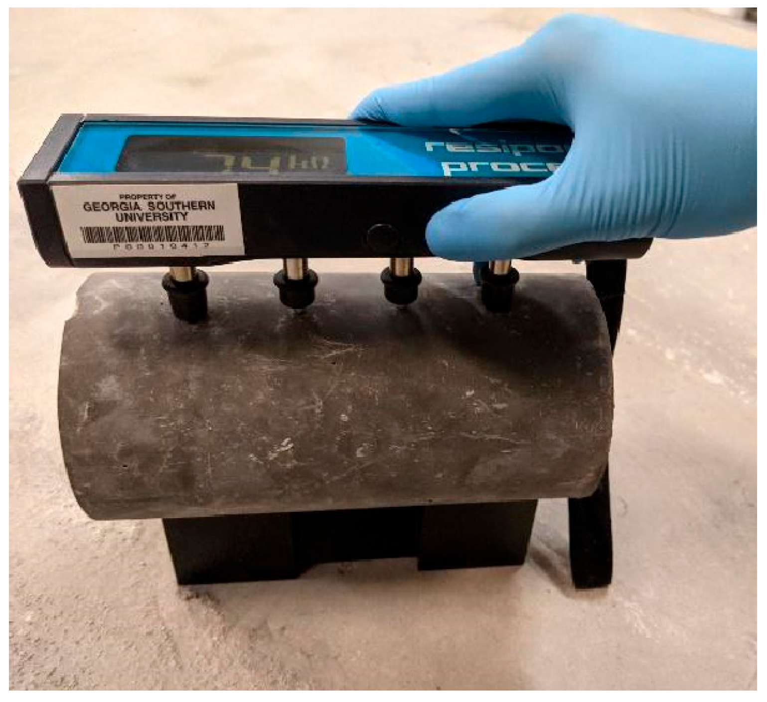
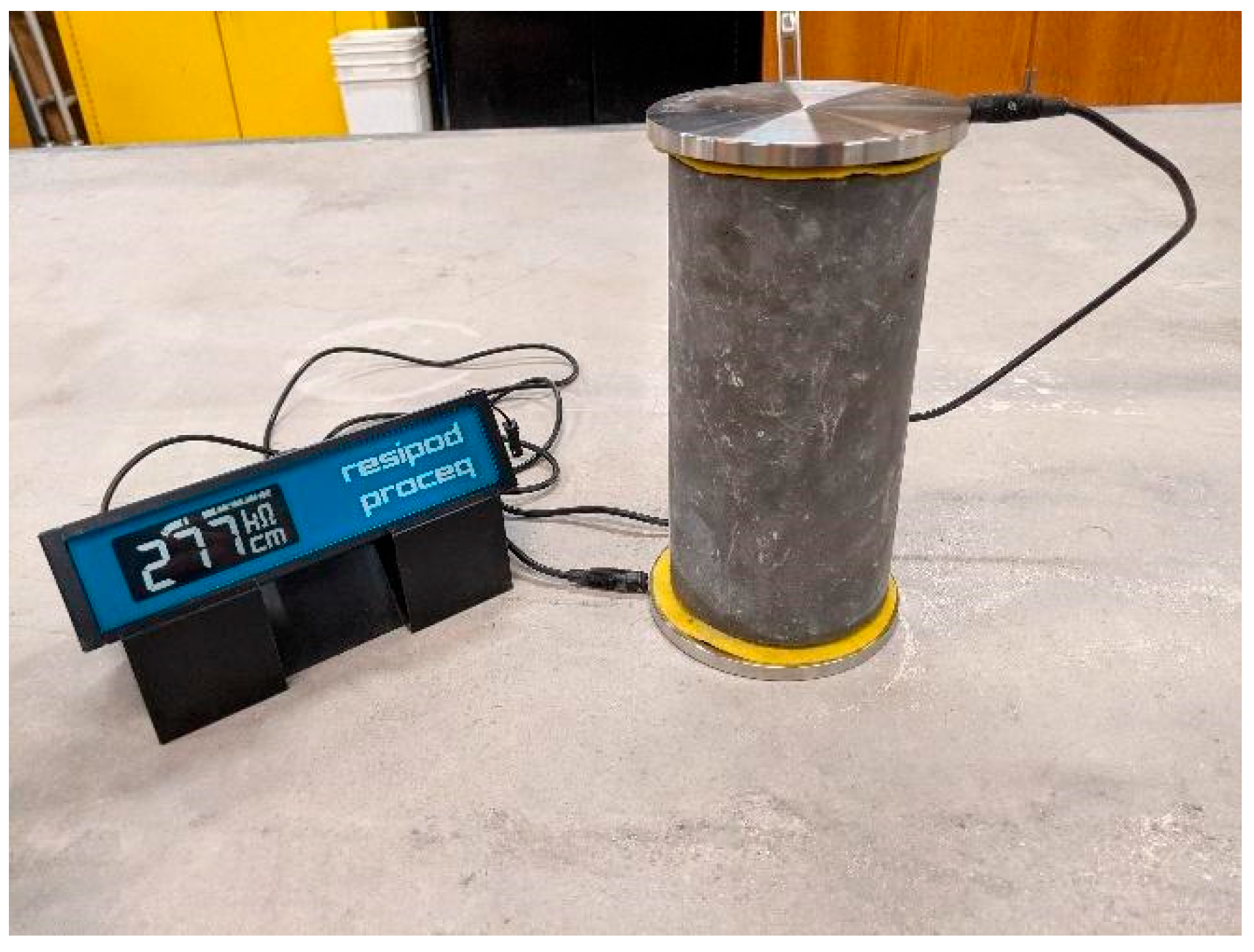
Bulk and surface resistivity testing, as shown in
Figure 1 and
Figure 2, respectively, are the two most common non-destructive methods used to measure the electrical resistivity of reinforced concrete [
31,
32]. In bulk resistivity testing, two electrodes are placed on opposite ends of the specimen, with moist sponges positioned between the electrodes and the sample to ensure electrical contact. The geometric factor (k) for this method can be calculated using the following equation:
where A is the cross-sectional area perpendicular to the direction of current flow, and L is the height of the specimen.
Surface resistivity testing involves placing an electrode disk over the reinforcing bar (rebar) to measure the electrical resistance of the concrete between the disk and the rebar. In this method, a cell constant is used to calculate resistivity, with the constant depending on both the rebar diameter and the concrete cover depth. The resistivity for this test can be determined using the following equation:
Although ER testing is effective for both laboratory and field applications, several limitations must be considered when using this method. The presence of embedded rebars can cause distortion in electrical readings. This effect can be minimized by positioning the electrodes perpendicular to the reinforcement within the concrete. Taking multiple measurements a few millimeters apart can also reduce the impact of electrical interference.
Cracking within the concrete can affect ER results because the method assumes the material is homogeneous, isotropic, and uncracked [
31]. Depending on the nature of the cracks, the electrical signal may be either insulated, resulting in lower readings, or conducted, resulting in higher readings.
Moisture and temperature also influence ER measurements. As the temperature increases, the electrical conductivity increases. Conversely, higher moisture content generally decreases resistivity. These factors should always be accounted for to ensure accurate, reliable, and repeatable results when performing ER testing.
3.2.2. Acoustic Emission
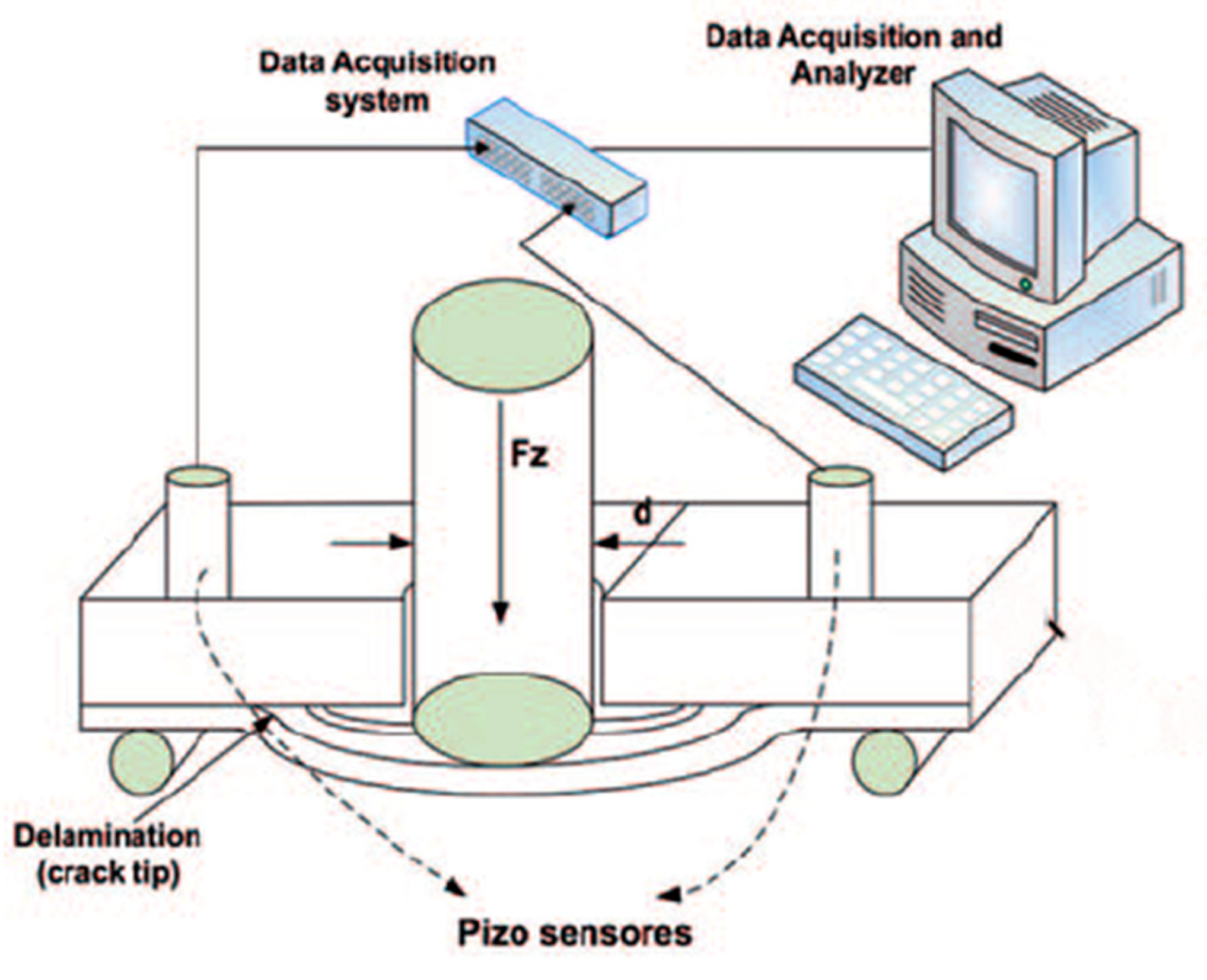
Acoustic Emission (AE) testing uses elastic ultrasonic waves that travel through a material to evaluate its internal structure [
33,
34]. AE employs an ultrasonic emitter and a set of sensors that convert acoustic signals into electrical outputs, enabling internal imaging and defect localization.
A parameter-based technique is commonly used to interpret AE data. This method analyzes hits or events and their signal amplitudes to map the internal condition of reinforced concrete. AE data can identify the presence of micro-cracks caused by ion attacks as well as other forms of corrosion and deterioration occurring within the concrete structure.
AE testing also uses rate process analysis to evaluate the behavior of concrete under compression. This approach considers the gradual accumulation of micro-cracks that eventually lead to specimen fracture [
35,
36,
37]. Because micro-crack formation is stochastic in nature, rate process theory is applied to numerically evaluate the number of AE events produced by incremental increases in stress, as expressed in the following equation:
where N is the total number of AE events and ƒ(V) is the probability function of AE activity at stress level V(%). A hyperbolic function ƒ (V) is assumed,
where a and b are empirical constants. ‘a’ is called the rate because it reflects AE activity at a given stress level [
36]. Substituting Equation (17) into Equation (18) gives a relationship between the total number of events N and the stress level:
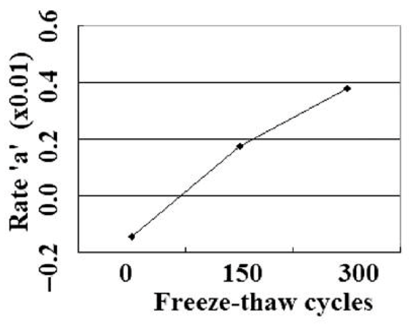
where C is the integration constant. The constant ‘a’ is a sensitive parameter to the damage degree and is closely related to the freeze–thaw cycle as shown in
Figure 3. ‘a’ represents a dimensionless intensity parameter describing the activity level of acoustic emission events per stress level increment according to the mathematical model in Equations (17)–(19).
Testing has shown that as chloride ion penetration increases, the signal strength of AE hits also increases, confirming that AE can be effectively used to detect chloride ingress. The ability of AE to capture micro-crack development enables more accurate analysis of the early stages of ion-induced deterioration in reinforced concrete.
AE is a valuable field testing method that excels at locating cracking within structures but also has certain limitations. The results of AE testing are material-dependent, varying according to the composition and properties of the structure. AE testing requires the application of external stresses to obtain accurate readings, which can restrict its use in some situations [
37]. Each AE event produces a unique and non-repeatable data signature, unlike many other NDT techniques. The amount of data collected is also limited by the number of sensors used during the testing period (
Figure 4). Increasing the number of sensors expands both the coverage area and the quantity of recorded data.
3.2.3. Infrared Thermography
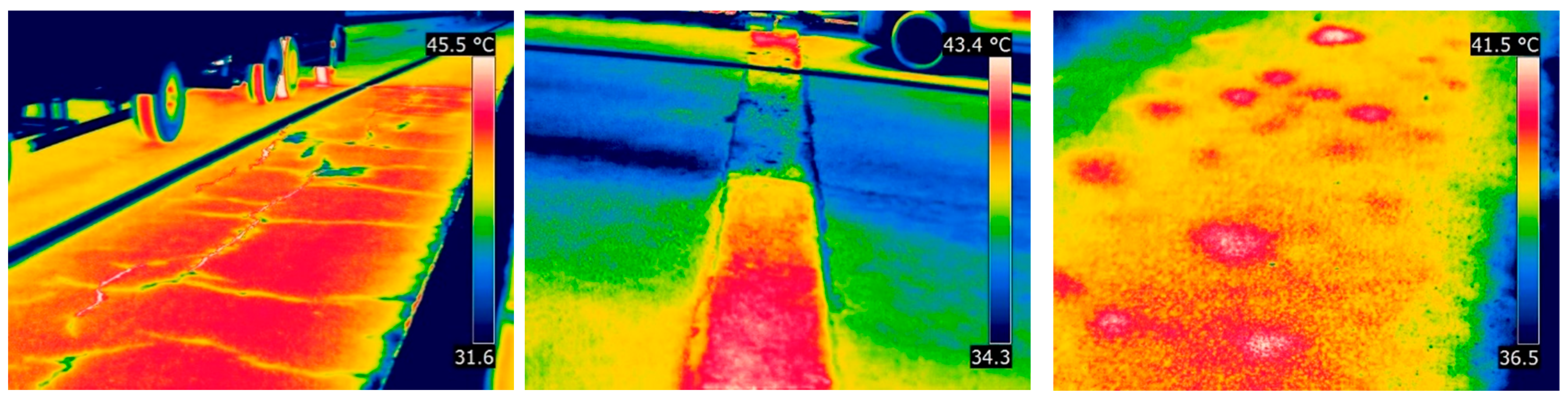
Infrared radiation is the energy emitted by a surface with a temperature above absolute zero. Infrared Thermography Testing (IRT) measures the infrared radiation emitted from an object and converts it into a visual image or thermal map [
38]. IRT relies on differences in heat absorption rates to detect damaged areas within concrete, typically to a depth of about 6 inches [
39]. Cracks, voids, and other forms of deterioration can be effectively identified using this method (
Figure 5).
Applying IRT to concrete is more challenging than to materials such as steel or other metals because concrete has low thermal conductivity. As a result, greater energy input is required to alter the temperature of concrete, making the process more resource-intensive. IRT performs best on concrete surfaces exposed to direct sunlight, which enhances temperature contrast and improves image clarity.
Active IRT can also be used to examine concrete. This method utilizes an artificial heat source to generate a thermal gradient within the material, enabling greater control over the surface temperature during testing [
40]. Although more controllable, active IRT requires additional energy and labor, making it a more resource-intensive approach.
IRT results are most reliable when used in combination with other NDT techniques. It is particularly effective for broadly identifying regions of concern within a concrete structure, after which complementary NDT methods can be employed to evaluate the affected areas in greater detail.
3.2.4. Ground Penetrating Radar
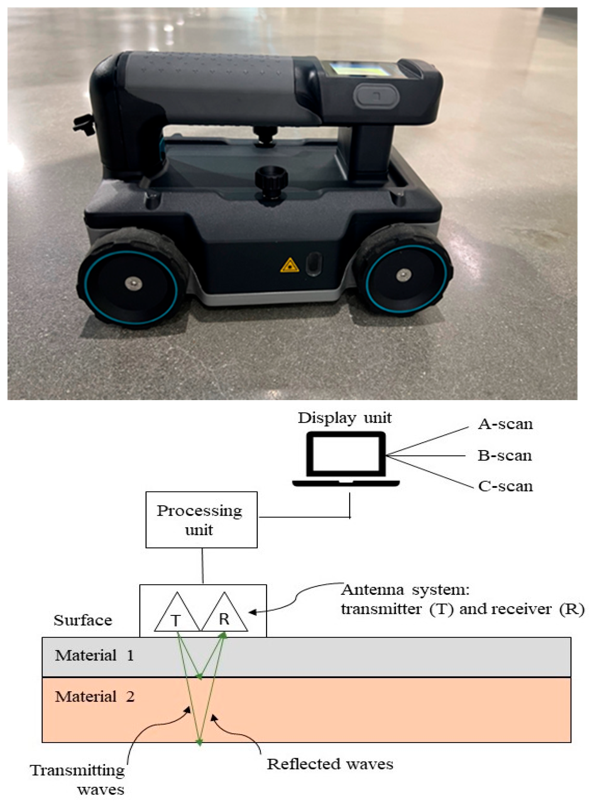
Ground Penetrating Radar (GPR) is a non-destructive testing method that uses the propagation of short electromagnetic pulses to detect inhomogeneities within a material [
41,
42]. The measurement system typically consists of three main components: a central computer and data storage unit, a control unit, and an antenna system.
GPR is used to determine the internal structure of reinforced concrete and to identify cracks, voids, and other inconsistencies (
Figure 6). The propagation velocity of the radar pulses and the intensity of their reflections depend on the dielectric properties of the material, which are defined by the complex permittivity (ε) of the medium:
where ε is the complex permittivity, ε′ is the real part of the complex permittivity, and ε″ is the imaginary part of the complex permittivity. A relation between the propagation velocity of the electromagnetic impulses and the permittivity can be approximated:
One limitation of GPR is that the control unit must remain in direct contact with the concrete surface to ensure accurate data collection. Because of this, GPR is best suited for testing large, flat areas of concrete such as slabs, bridge decks, and other level surfaces. The operating frequency typically ranges from 10 MHz to 2.6 GHz, where lower frequencies provide deeper penetration and higher frequencies allow for shallower, higher-resolution imaging [
44,
45,
46].
3.2.5. Ultrasonic Pulse Velocity
Ultrasonic Pulse Velocity (UPV) is a non-destructive testing method that uses the propagation of ultrasonic waves to evaluate the internal condition of cementitious materials. By measuring wave velocity, UPV can determine material properties, detect defects, and assess deterioration [
47]. UPV waves propagate in three forms: longitudinal (P) waves, shear (S) waves, and Rayleigh (R or surface) waves [
48]. P-waves and S-waves travel in a spherical pattern through the material, while R-waves move along its surface. UPV testing equipment typically consists of a transmitter, a receiver, and a data acquisition unit. The positioning of the transmitter and receiver depends on the geometry of the structure, and the collected data are influenced by their relative placement.
Two main transmission methods are used in UPV testing: direct (through-thickness) and indirect (surface) transmission. Direct transmission is the most common, as the pulse amplitude received is highest when the transmitter and receiver are placed on opposite sides and aligned directly with one another [
48]. In the indirect method, both the transmitter and receiver are placed on the same surface of the material [
49]. Assuming the concrete behaves elastically, the propagation velocity for direct transmission can be expressed as:
where V
p is the wave velocity, M is the constrained modulus, E is Young’s modulus, ρ is the density and υ is Poisson’s ratio [
47,
48,
49,
50].
UPV is widely used for the non-destructive evaluation of concrete, particularly for estimating compressive strength and identifying inconsistencies within its internal structure. The method can also detect areas of deterioration caused by ion attacks. Analysis of UPV wave travel times helps reveal cracking, voids, and other forms of internal deformation within concrete structures [
50].
To strengthen the theoretical foundation of Equation (22), it is important to recognize that this relationship between ultrasonic wave velocity, elastic modulus, density, and Poisson ratio has been widely established in the mechanics of elastic materials. Several studies have demonstrated that the equation is valid for cementitious systems provided that the concrete behaves as a continuous elastic medium and the heterogeneity effects are minimized during testing [
47,
48,
49]. Earlier work has shown that wave velocity is directly influenced by changes in stiffness caused by micro cracking, porosity variation, and ionic deterioration, which enables UPV to serve as a sensitive indicator of internal structural changes under both chloride and sulfate attack. Additional research confirms that deviations from ideal elastic behavior can alter the accuracy of Equation (22), especially in damaged or highly porous concrete, and therefore the interpretation of UPV results should always consider material condition, moisture level, and wave scattering effects reported in the literature. These studies collectively support the applicability of Equation (22) while also highlighting the need for careful evaluation of testing conditions when using UPV for durability assessment [
48,
49,
50].
4. Case Studies and Applications of NDT
4.1. Overview of Case Studies
NDT methods have been widely applied to examine reinforced concrete through various methodologies and techniques. The use of NDT enables ongoing evaluation of concrete structures that have been exposed to chloride and sulfate ion attacks. Numerous studies have investigated the effects of these ion attacks on reinforced concrete using different NDT approaches [
45,
46,
51,
52,
53,
54,
55,
56,
57,
58,
59,
60].
The following case studies illustrate the practical applications of NDT, showcasing real-world implementations for detecting and assessing ion-induced deterioration in reinforced concrete structures.
4.2. Utilizing NDT for the Examination of Ion Attacks
4.2.1. Electrical Resistivity Studies
Electrical Resistivity (ER) testing has been widely used to examine chloride-induced corrosion of steel reinforcement in concrete. A study investigated chloride ion penetration in marine environments using surface ER testing. Corroded concrete specimens from coastal regions were selected for evaluation. ER and chloride profile data were collected, compared, and analyzed to develop correlation models. The results showed that lower surface electrical resistivity values were associated with higher levels of chloride penetration [
51].
Another study applied ER imaging to monitor crack development in concrete beams. Concrete specimens with known artificial crack locations were prepared and equipped with electrodes to enable continuous monitoring. The collected data and imaging demonstrated that ER testing can effectively identify both the location and depth of cracking in concrete [
52].
These case studies highlight the successful application of ER testing for detecting and assessing ion-induced deterioration. When used to monitor chloride ions, ER testing enables the detection of chloride-related cracking and other inconsistencies. Overall, ER is a practical and reliable NDT technique for observing changes in reinforced concrete caused by ion penetration.
4.2.2. Acoustic Emission Studies
Acoustic Emission (AE) testing of ion penetration focuses on detecting chloride-induced cracking. One study examined corrosion mechanisms in reinforced concrete using AE. Beam specimens of 28-day cured concrete were subjected to cyclic wet–dry testing to simulate salt attack. Six sensors were placed along each concrete beam to collect AE data. After testing, the beams were cut in half to compare the collected AE data with the microstructure around the reinforcing bars. The results showed that AE analysis could identify both the onset of corrosion and the formation of cracks [
53].
Another study conducted an experimental evaluation of the distribution of corrosion damage in reinforced concrete. Concrete specimens containing centered rebar reinforcement were prepared, and twenty-five samples with varying salt concentrations were tested. The corrosion ratio of corroded steel mass to the original steel mass was theoretically calculated and compared with AE-derived data. The AE data were modeled mathematically, and the resulting analysis effectively demonstrated a reliable method for locating and quantifying corrosion across steel reinforcement [
54].
These case studies demonstrate the effective application of AE testing for assessing chloride-induced corrosion in reinforced concrete. The propagation of ultrasonic waves through concrete enables the identification of corrosion sites and the assessment of their severity. Both studies highlight AE testing as an ideal technique for examining corroded rebar and monitoring its degradation over time.
4.2.3. Infrared Thermography Studies
Infrared Thermography (IRT) is used to detect flaws and defects in concrete based on temperature variations within surrounding areas. One study tested several NDT methods to evaluate their effectiveness. Concrete slabs with thicknesses of 100 mm, 200 mm, and 300 mm were cast with known deformations, including honeycombing, delamination, and voids. IRT was applied to assess its capability in locating these defects. The study found that, due to low ambient temperature during testing, IRT was able to detect deformations only in the 100 mm slab. Thermographic data was processed using MATLAB software (version 3), and the analysis showed a 36.8% error in determining void areas [
55].
Another study evaluated the effectiveness of IRT for detecting delamination in reinforced concrete bridge decks. An unmanned aerial system equipped with an infrared thermal camera was used to inspect the bridge deck for delamination and other deformations. Captured images were analyzed using a delamination detection model to process and interpret the results. The data obtained from the model demonstrated that IRT has strong potential for assessing bridge decks for structural irregularities, though further refinement of the method was recommended [
56].
These case studies illustrate how IRT can be applied to evaluate concrete structures, highlighting both its strengths and limitations. IRT is most effective for identifying broad regions of concern associated with chloride and sulfate penetration. Unlike other NDT methods, IRT relies on image-based data that must be processed to extract useful information. When used in combination with other NDT techniques, IRT enhances the accuracy and reliability of ion penetration detection.
4.2.4. Ground Penetrating Radar Studies
Ground Penetrating Radar (GPR) uses radar waves to produce subsurface images and detect the internal structure of reinforced concrete. One study applied GPR to analyze the moisture and chloride content in concrete. Unreinforced slab samples were cast with high-permeability concrete to allow greater water absorption. One sample served as a control, six samples were prepared to evaluate the effects of moisture content, and twenty-four samples were used for chloride penetration testing. GPR signal acquisition was performed on the surface of the specimens. Analysis of the control sample informed the evaluation and modeling of the remaining samples. During testing, signal amplitude in moisture-rich specimens was strongly influenced by water content. Chloride-contaminated samples exhibited higher amplitude attenuation than the moisture-rich samples because chloride ions enhanced conduction within the electric field of the GPR antenna. Nonlinear models were developed to estimate both moisture content and chloride presence in concrete [
57].
Another study examined the influence of environmental factors on GPR measurements. Reinforced concrete samples containing both corroded and standard rebar were tested at various temperatures and moisture levels. The results showed a significant increase in GPR signal strength when assessing corroded rebar. Secondary testing confirmed that temperature affected signal quality, producing greater amplitude attenuation at higher temperatures [
45,
46,
58].
These case studies provide valuable insight into the effective application of GPR for evaluating concrete structures and detecting harmful ions. The use of both direct and indirect radar waves enables detailed subsurface imaging, offering greater resolution compared to many other NDT methods. The studies also emphasize the importance of accounting for environmental conditions such as temperature and humidity, as these factors influence GPR readings. Overall, GPR is an effective technique for assessing chloride-induced corrosion, sulfate-related voids, and moisture intrusion in reinforced concrete.
4.2.5. Ultrasonic Pulse Velocity Studies
Ultrasonic Pulse Velocity (UPV) testing has been applied to detect chloride ions in cement-based materials. One study evaluated UPV performance on NaCl-saturated cement paste specimens containing various mineral admixtures. Results showed that UPV could not directly detect fluid within the cement paste. However, a proportional relationship was observed between the amount of alumina and Friedel’s salt formed through chloride bonding and the amplitude average frequency of the UPV signal [
59].
Another study investigated the use of UPV to analyze alkali–silica reaction (ASR) damage in concrete under both laboratory and field conditions. The velocities of P-waves and S-waves were recorded over time for both reactive and non-reactive specimens. Data from both environments showed that P- and S-waves exhibited similar trends when evaluating reactive specimens, with a slight reduction in the expansion of the reactive concrete. Compressive strength was minimally affected by the ASR, with most deterioration occurring near the surface of the specimens [
60].
These case studies demonstrate the effective use of UPV testing for identifying ion penetration and related deterioration in concrete. Although direct measurement of moisture content is limited, UPV is well-suited for indirectly assessing chloride reactions by measuring salt formation associated with chloride-induced corrosion. Both studies confirm UPV’s capability for detecting internal deformations and estimating the compressive strength of concrete.
4.3. Comparison of Methods
Each of the previously discussed NDT methods offers distinct advantages and limitations for evaluating ion penetration in concrete, making each more suitable for specific applications (
Table 2). Understanding the strengths and weaknesses of these methods enables the optimal selection and application of them in assessing reinforced concrete deterioration.
ER testing is an effective technique for monitoring chloride-induced corrosion, providing valuable data for evaluating structural integrity. AE is well-suited for corrosion monitoring because of its ability to detect micro-cracking caused by chloride corrosion of reinforcement. IRT is most effective for identifying potential zones of ion penetration through temperature variations that result from moisture or ion movement. GPR excels at detecting voids and irregularities within concrete, making it particularly suitable for assessing unseen sulfate-related deterioration and larger chloride-induced cracking. UPV is best applied for detecting internal deterioration and estimating the compressive strength of concrete.
5. Advances and Innovations
Recent Development and Improvements
As technological advancements continue and research methodologies improve, the accuracy, precision, and effectiveness of non-destructive testing (NDT) also increase. Numerous refinements have been made in both the theoretical and practical applications of NDT [
43,
45,
46,
61,
62,
63]. As these methods become more reliable and widely accepted, their use has expanded, leading to improved structural health monitoring of concrete infrastructure. Recent research has demonstrated improved sensitivity of GPR to early corrosion initiation under chloride exposure, enhanced interpretation of frequency domain responses for assessing corrosivity, and automated field scale corrosion mapping techniques [
45,
46,
63]. These improvements provide earlier detection of deterioration mechanisms, which enables preventive maintenance strategies and reduces long term repair costs for aging infrastructure networks.
Many studies have explored enhancements to NDT techniques and their applications in field conditions [
43,
45,
46,
61,
62,
63,
64,
65]. A review of NDT improvements for structural health monitoring highlighted advancements in methodology and technology across multiple techniques [
61]. The Sweep Frequency Technique (SFT), for example, is a microwave-based method that uses two wideband horn antennas, a network analyzer, and a computer interface. Operating within a frequency range of 2 to 13 GHz, SFT collects reflected signal data to measure moisture and chloride content in concrete. In addition, GPR data analysis and interpretation have been improved through approaches such as neural networks, data preprocessing, frequency domain mapping, and automated rebar detection frameworks, all of which increase accuracy and reduce subjectivity in field evaluations [
45,
46,
63,
64]. These methodological refinements allow practitioners to use NDT tools more confidently in environments where traditional methods may be limited by access, traffic conditions, or surface constraints. The integration of drones equipped with IRT cameras, along with advancements in sensor performance, has further expanded the capabilities of remote structural evaluation by improving coverage and reducing the need for manual inspection.
Another advancement involves the application of Near-Infrared Spectroscopy (NIR) for analyzing water and chlorine content in cement paste. Using NIR spectroscopic techniques, moisture and chloride ion concentrations can be determined by interpreting absorption values [
62]. This method enables rapid, simultaneous inspection of multiple concrete components and enhances the potential for detecting both sulfate and chloride ions within concrete. The ability to characterize ionic transport processes quickly and accurately is increasingly important for assessing the long-term durability of reinforced concrete exposed to marine, deicing, or high moisture environments.
As testing methodologies and technologies continue to evolve, NDT will become increasingly efficient and reliable [
63,
64]. The integration of artificial intelligence, neural networks, and other advanced data interpretation tools will allow for more automated and accurate analysis. Recent developments in machine learning applied to multi modal NDT data, including convolution-based interpretation of GPR scans and ensemble-based prediction of concrete properties, demonstrate the growing capabilities of automated diagnostic systems [
64,
65]. These approaches support objective decision making and reduce dependence on technician experience, which can vary widely across field conditions. Continued innovation in NDT will support more precise localization, detection, and diagnosis of ion attacks in reinforced concrete structures [
65], ultimately contributing to safer and more resilient infrastructure systems.
6. Conclusions
This paper reviewed the applications of non-destructive testing methods for examining the effects of chloride and sulfate ion penetration in reinforced concrete. NDT techniques have proven to be valuable tools for detecting ion ingress, assessing the resulting corrosion of reinforcement, and identifying concrete deterioration before structural failure occurs. Because chloride and sulfate ions pose significant risks to structural durability, understanding and applying NDT methods is essential for extending service life and ensuring safety. The discussion and case studies presented in this review highlight the capabilities, limitations, and best-use scenarios of major NDT techniques. Electrical Resistivity provides valuable data for monitoring chloride-induced corrosion; Acoustic Emission enables early detection of micro-cracking caused by ion activity; Infrared Thermography allows surface-level mapping of temperature variations linked to ion transport; Ground Penetrating Radar effectively locates voids, cracks, and subsurface irregularities; and Ultrasonic Pulse Velocity assesses internal deterioration and compressive strength. These methods are proven to offer complementary insights into the condition of reinforced concrete structures.
One of the ongoing challenges for the continued advancement of NDT is the reliable interpretation of complex data. While progress has been made through enhanced signal processing, modeling, and sensor integration, data interpretation still limits accuracy in field conditions. Emerging technologies, such as artificial intelligence, neural networks, and machine learning models, are expected to play a crucial role in enhancing data analysis and predictive reliability. In summary, NDT remains an indispensable tool for structural assessment and maintenance. Its ability to identify penetration, track corrosion progression, and evaluate structural performance allows for early intervention and improved asset management. With continued development of analytical models, sensor technologies, and integrated testing systems, NDT will continue to advance as a precise and indispensable approach for diagnosing and mitigating chloride and sulfate ion attacks in reinforced concrete.