


Abstract
The paper represents the research results for the process of crude oil-contaminated soil neutralization with the use of a neutralizer obtained on the basis ofhumic substances. Using physical methods (gas and liquid chromatography, fluorimetry, atomic absorption spectrometry, IR spectrometry), the element and group compositionswere determined for the crude oil-contaminated soil, neutralizer, and neutralized soil. Optimal parameters were determined for the process of the crude oil-contaminated soil neutralization under laboratory conditions:weight ratios of the crude oil-contaminated soil, neutralizer and water, and the temperature and neutralization process duration. The technological scheme was developed for the neutralization of the crude oil-contaminated soil in field conditions. It was found that low-boiling point hydrocarbon fractions (C12–C17) disappear completely at neutralization, the content of high-boiling point hydrocarbon fractions (C20–C23) is essentially increased, and the content of oil components and metals, including the toxic ones, is decreased. The engineering characteristics for nine mixtures of the stabilized soil, containing the neutralized soil, were evaluated under laboratory conditions and the conditions were determined for their use in road construction (with regard to road category, characteristic pavement layer, minimal air temperature). An experimental road section was constructed with the use of the stabilized soil with neutralized soil (40%).
1. Introduction
Crude oil spill occurs on the earth’s surface at oil production, transportation, and storage. Soil contaminated with oil (crude oil-contaminated soil) is dangerous for human health, flora, and fauna. Therefore, one of the actual problems forthenormal functioning of biological and ecological systems in the regions with oil production is efficient remediation and utilization of crude oil-contaminated soil.
The most important genetic soil characteristics are disturbed at oil contamination: content and composition of humus, nitrogen, phosphorous, and other chemical elements vary; soil adsorption capacity is reduced, density is increased, aeration and water penetration are reduced, and plant available moisture content is decreased [1,2].
Natural self-purification of natural objects from oil contamination is a time-consuming process. Therefore, short-time efficient artificial methods are required for purification. At present, the following methods are known for remediation of crude oil-contaminated soil: biological [3,4,5,6,7,8], chemical [9,10,11,12,13,14,15,16,17], thermal [18], ultrasound [19], and mechanical [20,21]. The purpose of most of remediation methods mentioned above is to extract oil from crude oil-contaminated soil. As a rule, these methods are expensive.
This paper suggests a method fortheneutralization of crude oil-contaminated soil with the use of neutralizer produced on the basis of a sodium humate, and the possibility is shown for the use of the neutralized soil in road construction.
2. Materials and Methods
2.1. Crude Oil-Contaminated Soil
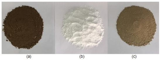
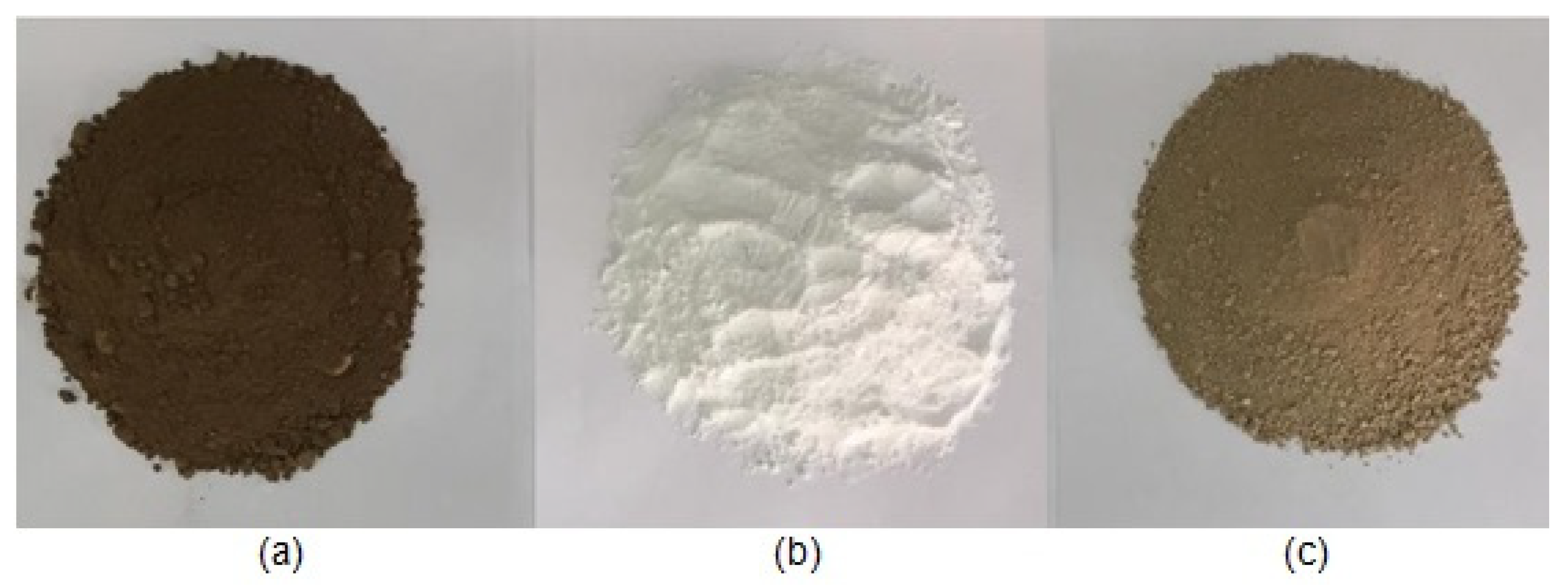
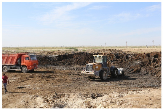
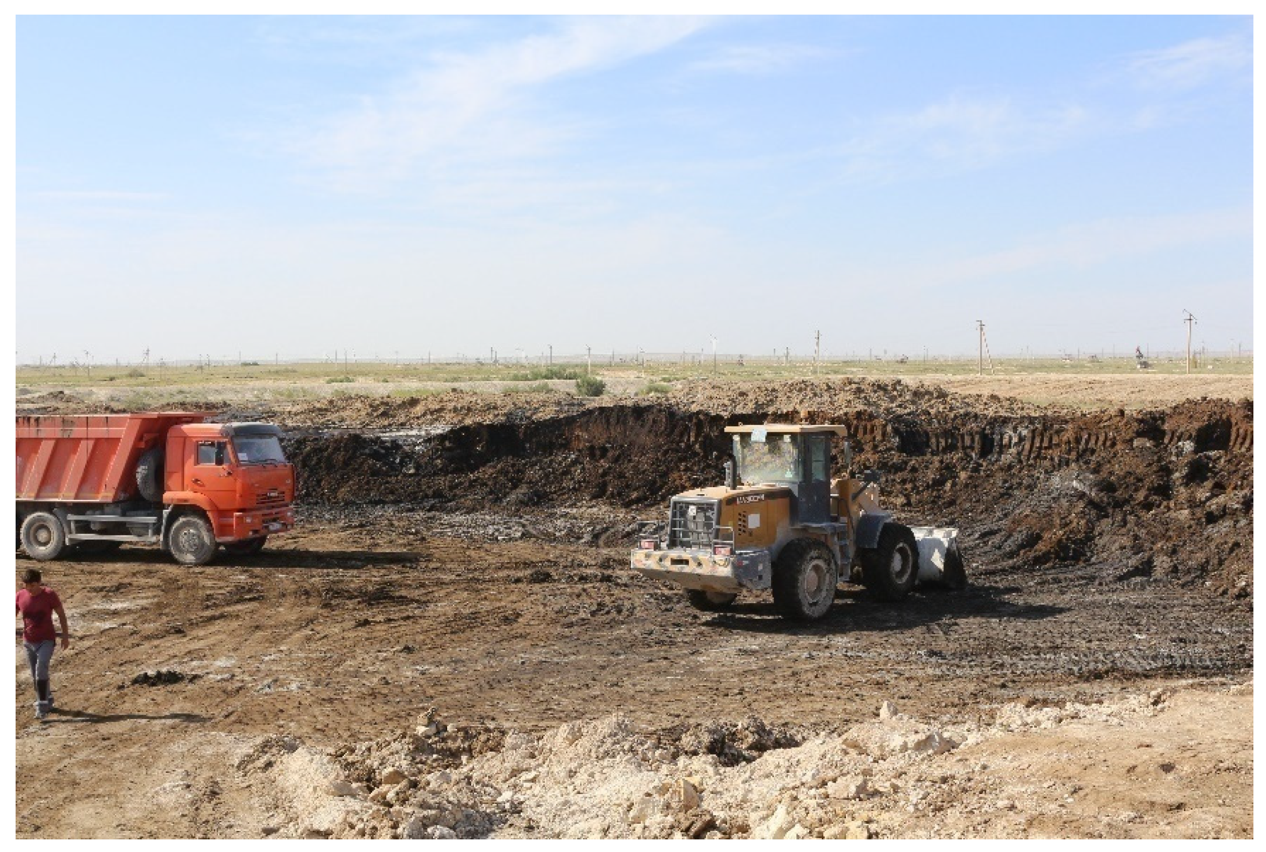
Crude oil-contaminated soil (Figure 1a) belonging to JSC (Joint-Stock Company) “Ozenmunaigas” (Mangistau region, Kazakhstan) was taken for further purification and improvement of the properties with the purpose of its use in a subbase of a highway. A storage facility for crude oil-contaminated soils is shown in Figure 2.
Figure 1.
(a) Crude oil-contaminated soil; (b) neutralizer; (c) neutralized soil.
Figure 2.
Storage facility for crude oil-contaminated soil.
2.2. Neutralizer
To purify the crude oil-contaminated soil from oil components, a neutralizer was used (Figure 1b), produced on the basis of humic substances which has the following composition (% by weight): humic acids—2.40; moisture—15.25; ash—12.35. The neutralizer was developed by the A.B.Bekturov Institute of Chemical Sciences (Kazakhstan).
2.3. Chemical Analysis Methods
Fractional composition of oil components in the crude oil-contaminated soil and the neutralized soil was determined by the methods of gas and liquid chromatography (chromatograph “Agilent 6890”, USA) and fluorimetry (“Fluorat-02”, Russia, Moscow, RF) [22,23]. N-hexane was used as an extractant. Accuracy for determination of fractional composition content is (1.5–2.0)·10−3 mg/mL.
Content of metals in the crude oil-contaminated soil and the neutralized soil was determined by the method of atomic absorption spectrometry [24,25] (spectrometer AA-240 “Varian Inc. Scientific Instruments”, Australia). Analysis of organic fraction of the crude oil-contaminated soil and the neutralized soil was performed on IR-spectrophotometer (FTIR) of the model Nicolet 5700 (company “Thermo Electron”, USA) within the range of wave numbers 4000–400 cm−1. The analyzed soil samples were prepared with KBr.
The quantitative content of metal oxides was determined by the spectral method (Spectrophotometer Lambda-35 “Perkin Elmer”, USA) [26].
2.4. Neutralization of Crude Oil-Contaminated Soil
Due to multicomponent (complexity) of the crude oil-contaminated soil composition, and polyfunctionality and nonstoichiometry of the neutralizer composition, it is difficult to represent the chemical mechanism of the process for neutralization of the crude oil-contaminated soil. However, we suppose that neutralization of the crude oil-contaminated soil on the basis of the humate provides oxidation of hydrocarbons in oil components and bonding of heavy metals into safe non-soluble complexes. Toxic cations of metals (Pb2+, Cr3+, V5+, As2+, and others) in the process of neutralization are bonded into humates and become inactive and less dangerous for the environment. Methane hydrocarbons (paraffins), complex alicyclic resins, and asphaltenes are formed.
2.4.1. Neutralization under Laboratory Conditions
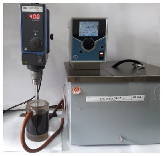
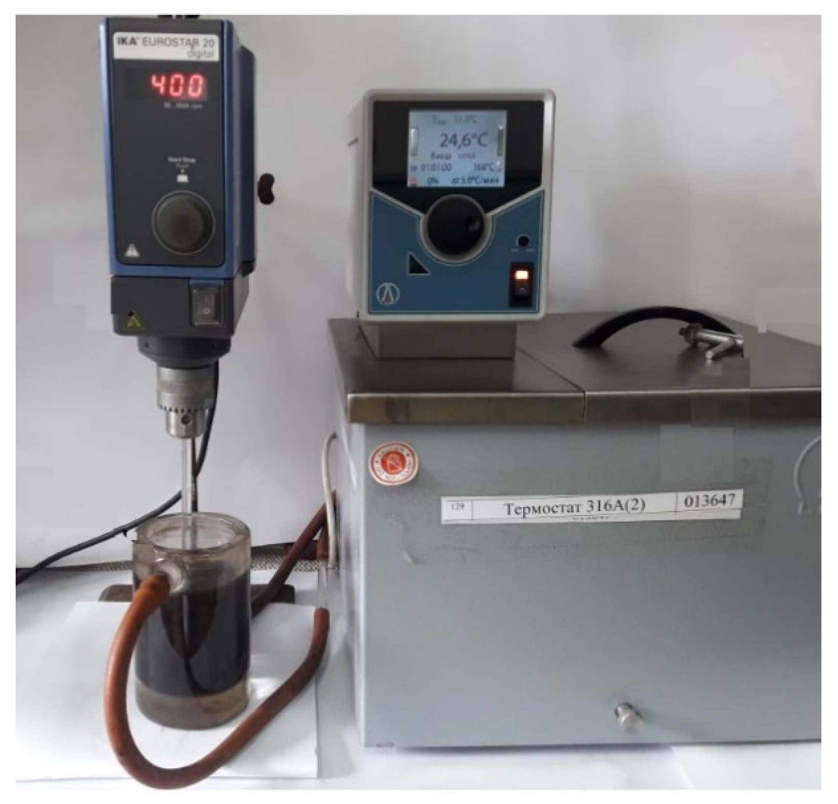
Neutralization of the crude oil-contaminated soil under laboratory conditions was performed by joint mixing (rate is 400 rotations per minute) of the crude oil-contaminated soil, the neutralizer, and water in specified ratios in a mechanical mixer with a thermostatical beaker of model “Eurostar 20 digital” (Figure 3). Ratios of weights for the neutralizer and water to the weight of the crude oil-contaminated soil in the tests varied from 0.05 to 1 and from 0.1 to 1, respectively. The temperature and process duration varied from 20 to 80 °C and from 5 to 60 min, respectively.
Figure 3.
Mechanical mixer.
The neutralized soil has a form, as in Figure 1c.
2.4.2. Neutralization under Production Conditions
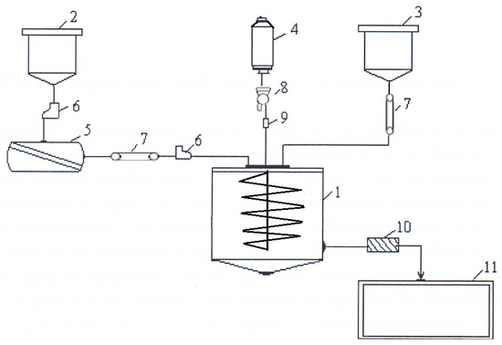
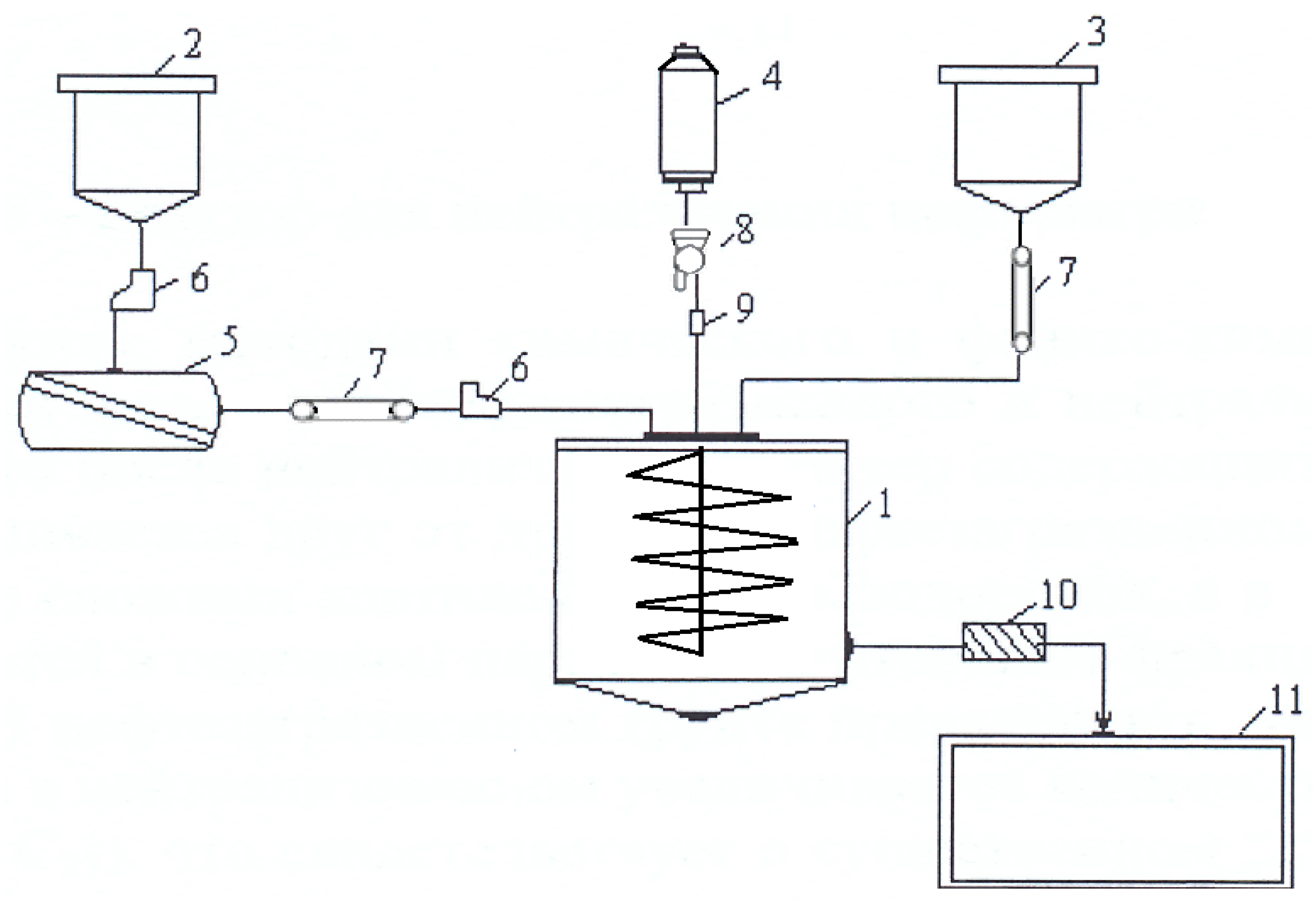
Neutralization process under the production conditions can be performed on standard equipment of chemical manufacturers according to the following technical scheme (Figure 4): the crude oil-contaminated soil from a tank (2) by a belt conveyor (6) is supplied into a crusher (5); the crushed (up to 0.5 mm) crude oil-contaminated soil by a belt dozer (7) and a belt conveyor (6) is supplied into a reactor (1); the neutralizer is supplied from the reactor (1) into a tank (3) by the belt dozer (7); water is also supplied into the reactor (1) from a tank (4) by a pump (8) and a dozer (9); the neutralized soil is supplied by a belt conveyor (10) into a tank (11).
Figure 4.
Technical scheme for the neutralization process of a crude oil-contaminated soil: 1—reactor; 2—tank for crude oil-contaminated soil; 3—tank for neutralizer; 4—tank for water; 5—crusher; 6—belt conveyer; 7—belt dozer; 8—pump; 9—dozer; 10—belt conveyor; 11—tank for neutralized soil.
2.5. Engineering Characteristics
2.5.1. Granulometric Composition
When determining granulometric compositions of the neutralized soil and stabilized soil mixes under the standard ST RK 1273-2004 [27], the specimens and the mixes were dried before in a drying oven at the temperature of 105 ± 5 °C up to constant weight. Then the specimens were sifted through a set of sieves. The sieves with dimensions 1.25, 0.63, 0.315, 0.16, 0.05 mm and 20, 10, 5, 2.5, 1.25, 0.63, 0.315, 0.16 mm were used for the neutralized soil and the stabilized soil mixes, respectively.
2.5.2. Content of Organic Substances
Content of organic substances in the neutralized soil was determined under standard ST RK 1280-2004 [28] by incineration of the soil sample (30 g) in a muffler at the temperature of 550 °C for 2 h up to constant weight. The soil sample was dried before in a drying oven at the temperature of 105 ± 5 °C up to constant weight and cooled up to room temperature in a desiccator.
2.5.3. Preparation of Stabilized Soil
To study the possibility for the use of the neutralized soil in the road construction, it was proposed that we consider different mix compositions of the stabilized soil containing crushed stone (5–20 mm), sand (0–5 mm), Portland cement (grade M 400), and water. Preparation of the stabilized soil mixes was performed under standard ST RK 1218-2003 [29] in the following way: the required quantity of crushed stone, sand, and Portland cement were added to the neutralized soil of the pre-determined weight; the mixture was carefully mixed in a mixer (rate 90 rotations per minute) for 3 min; then, after reaching of homogeneity of the dry mixture, water was added during mixing and the mixing of the wet mixture was in progress up to reaching its homogeneity; due to the fact that neutralized soil contains organic substances and this soil is a hydrophobic one, a humectant was introduced intothewater.
2.5.4. Sample Preparation
From prepared mixtures of the stabilized soil according to the standard ST RK 1218-2003 [29], cylindrical samples with dimensions d = h = 71.4 mm for compression test and samples in the form of a beam with dimensions 40 × 40 × 160 mm for bending test were made. The samples were compacted in appropriate molds under the stress of 20 MPa for 3 min. The prepared samples were in a wet environment for 28 days prior to testing.
2.5.5. Compression Strength
The strength of the stabilized soils at compression was determined according to ST RK 1218-2003 [29] by testing the cylindrical samples with dimensions d = h = 71.4 mm at the temperature of 20 °C. The sample was deformed during the test at a constant rate of 3 mm/min to failure.
Compression strength was calculated by the formula:
where P is load at which the sample had failed; F is an initial cross-sectional area of the sample.
2.5.6. Bending Strength
The strength of the stabilized soils at bending was determined according to ST RK 1218-2003 [29] by testing samples in the form of a beam with dimensions of 40x40x160 mm at the temperature of 20 °C. The tests were performed on the three-point bending scheme. The sample was deformed during the test at a constant rate of 3 mm/min to failure.
The bending strength is calculated by the formula:
where P is the load at which the sample had failed; b, h are width and height of the sample, respectively; l is a distance between supports.
2.5.7. Frost Resistance
Frost resistance of the stabilized soil in accordance with ST RK 973-2015 [30,31] was determined by the maximum number of freezing and thawing cycles, which it resists without significant (not more than 25%) reduction of compression strength.
Cyclic freezing and thawing were carried out in the following way: pre-water-saturated soil samples are placed in a freezer and held at the temperature of −18 ± 2 °C for 4 h; then the samples are placed in a water bath at the temperature of +18 ± 2 °C for 4 h. Further, the next freezing and thawing cycle is performed.
3. Results and Discussion
3.1. Group Composition of Crude Oil-Contaminated Soil
The results for determination of the chemical composition of the oil components contained in the crude oil-contaminated soil by gas and liquid chromatography and fluorimetry showed that the oil components in the crude oil-contaminated soil are in dissolved, emulsified, and solid states. Total hydrocarbon content in the crude oil-contaminated soil varies in a wide range (5–69%), depending on the sampling point. However, the fractional composition of the oil components is relatively uniform. As shown in Table 1, the main part of the oil components are represented by complex acetylene hydrocarbons (65–74%), the content of resins, paraffinic and naphthenic hydrocarbons varies from 20% to 33.5%, while the amount of light hydrocarbons is only 0.5% to 6.0%). Thus, it can be assumed that 70% of the oil components are complex acetylene hydrocarbons, and 30% of them are resins, medium molecular weight, and light hydrocarbons.
Table 1.
Total content of hydrocarbons and group composition of oil components in the crude oil-contaminated soil.
3.2. Neutralization of Crude Oil-Contaminated Soil
Table 2 shows the results of the multivariate process for neutralization of the crude oil-contaminated soil at different weight ratios of the crude oil-contaminated soil, the neutralizer, water, and at different temperatures. The neutralization process duration is 60 min.
Table 2.
Variation of neutralization degree of the crude oil-contaminated soil at different ratios of neutralizer and water (process duration is 60 min).
It can be seen from Table 2 that the neutralization process depends either on the neutralizer or on water content and temperature. The neutralizer content and temperature are the dominant ones. It is established that the greatest degree of neutralization (100%) is achievable, and it takes place at weight ratios of the crude oil-contaminated soil, the neutralizer, and water equal to 1:0.1:0.3.
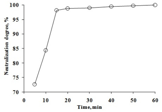
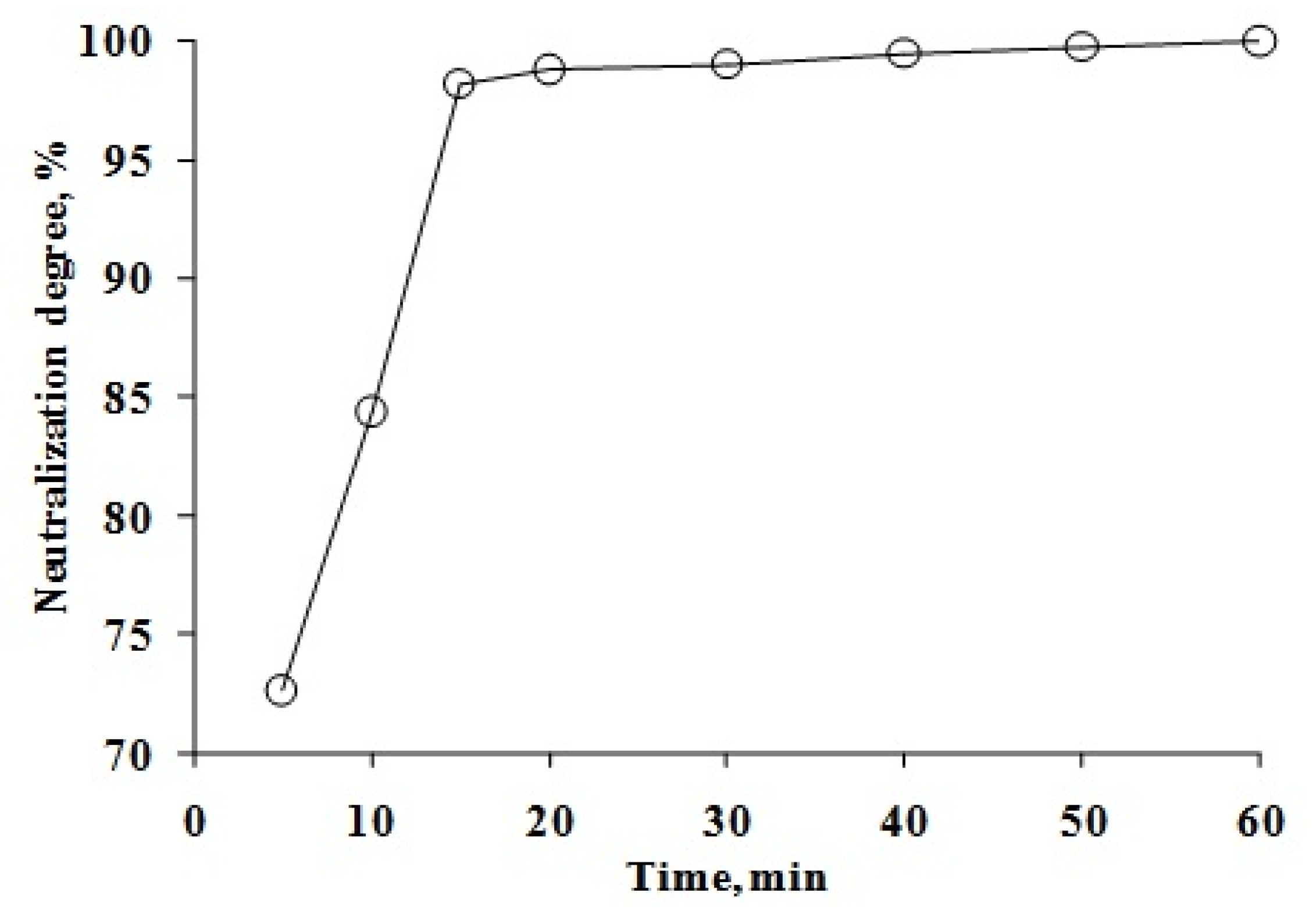
All treatments for neutralization of the crude oil-contaminated soil, the results of which are given in Table 2, had a duration of 60 min. Since the longer the duration of the neutralization process, the higher the costs, it is necessary to study the impact of treatment duration on the degree of neutralization of crude oil-contaminated soil. Figure 5 shows the neutralization degree asafunction of treatment duration. As can be seen, 15–20 min was sufficient to achieve the maximum possible degree (100%) of neutralization of the crude oil-contaminated soil.
Figure 5.
Dependence of neutralization degree for the crude oil-contaminated soil on the process duration.
3.3. Chemical Composition of Crude Oil-Contaminated Soil and Neutralized Soil
Comparative analysis of the fractional composition of oil components in the crude oil-contaminated soil and the neutralized soil has shown (see Table 3) that there are practically no low boiling point fractions (C12–C17) in the neutralized soil, but the content of high boiling point fractions (C18–C23) is significantly increased. This shows that neutralization of the crude oil-contaminated soil by the proposed method reduces its toxicity significantly.
Table 3.
Content of paraffins and alkanes in the crude oil-contaminated soil and the neutralized soil.
It should alsobenoted that the neutralization of the crude oil-contaminated soil involves an oxidation process whereby low-boiling-point acetylene hydrocarbons are converted to high-boiling-point hydrocarbons—paraffinic and naphthenic hydrocarbons, bitumen, and asphaltenes (Table 4).
Table 4.
Content of hydrocarbons in the crude oil-contaminated soil and the neutralized soil.
In the neutralization of the crude oil-contaminated soil, the total content of oil components and metals was decreased—the content of oil components was decreased by more than 260 times. The metal content was decreased from 2.4 times (Mo) to 20,000 times (V); the content of highly toxic metals (Pb, Cr, and As) was reduced by 6, 3, and 1500 times, respectively (Table 5).
Table 5.
Content of oil components and metals in the crude oil-contaminated soil and the neutralized soil.
Table 6 shows the chemical composition of solid particles for the crude oil-contaminated soil and the neutralized soil. The solid particles of the soil generally consist of silica oxide (SiO2—50.2%), calcium oxide (CaO—19.4%), and ferrum oxide (Fe2O3—15.2%), the total content of which is 84.8% (almost 85%). The rest of solid particles for soil (15.2%) is presented by magnesium oxide (MgO—4.8%), potassium oxide (K2O—4.1%), aluminum oxide (Al2O3—3.1%), sodium oxide (Na2O—2.1%), and phosphorus oxide (P2O5—1.1%). As can be seen from this table, the neutralization process does not practically change the chemical composition of the soil.
Table 6.
Content of oxides in the crude oil-contaminated soil and the neutralized soil.
3.4. IR-Spectra
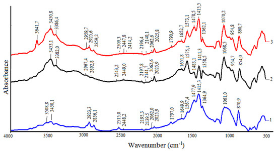
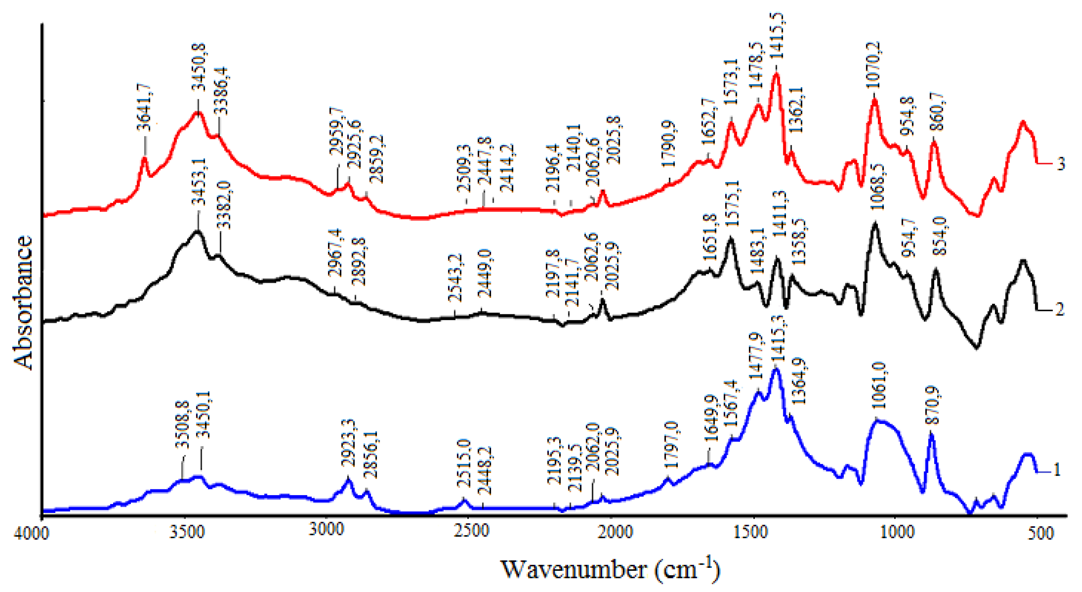
The interpretation of the IR-spectra of the investigated soils (Figure 6) was performed according to [32,33,34]. There were absorption peaks at 1364.9 cm−1, 1362.1 cm−1,and 1358.5 cm−1 in IR-spectra of the crude oil-contaminated soil, the neutralized soil, and the neutralizer, respectively, characterizing the symmetrical deformation vibration of C–H bond in methyl (CH3) groups. More intense absorption peaks were found at 1477.9 cm−1, 1478.5 cm−1,and 1483.1 cm−1,corresponding to the C–H bond deformation vibration in methylene (CH2) groups. Two groups of absorption peaks at 2856.1 cm−1, 2859.2 cm−1, 2892.8 cm−1, and 2923.3 cm−1, 2925.6 (2959.7) cm−1, 2967.4 cm−1 indicate valence vibrations of the C–H bond in methyl and methylene groups. A comparison of the corresponding absorption intensities showed that after the neutralization, the methyl and methylene group contents were reduced by an average of 30–40%.
Figure 6.
IR-spectra of samples: 1—crude oil-contaminated soil; 2—neutralizer; 3—neutralized soil.
It is known that the symmetrical deformation vibration of the C–H bond in methyl groups is shown at about 1375 cm−1, but in the composition of complex compounds, it moves towards low frequencies and has a higher intensity due to the neighborhood with the carbonyl group (C=O) [33]. Absorption peaks at 1797.2 cm−1 and 1790.9 cm−1 correspond to the valence vibration of the carbonyl group of a high-molecular hydrocarbons fragment. The neutralizer had no absorption peaks in this energy range. In addition, the absorption degree of the carbonyl group in the crude oil-contaminated soil is 29% higher than in the neutralized soil, which can give information onthereduction of asphaltenes content after neutralization.
Absorption peaks of 1415.3 cm−1, 1415.5 cm−1, and 1411.3 cm−1 on the spectra of the crude oil-contaminated soil, the neutralized soil, and the neutralizer indicate the presence of carbonate-anion . Content of the carbonate-anion is less in the neutralized soil by 33% than in the crude oil-contaminated soil. This can be explained by the decomposition of carbonates during the neutralization process:
MeCO3 + 2OH− ↔ Me(OH)2 + CO32−,
CO32− + 2 H+ → H2O + CO2↑.
The remainder of the anion is in the neutralized soil in the form of metal carbonates, mainly calcium carbonate, since the calcium content is substantially higher than that of sodium, potassium, and magnesium (Table 6):
Ca(OH)2 + CO2 → CaCO3 + H2O.
The presence of carboxylic acids (-COOH) having an internal hydrogen bond is confirmed by peaks at 1649.9 cm−1 (crude oil-contaminated soil), 1652.7 cm−1 (neutralized soil), and 1651.8 cm−1 (neutralizer). The availability of the carboxylic acid absorption band is due to the presence of humic additives in the reaction mixture. At the same time, their content is more by 47% and 29% in the neutralizer and the crude oil-contaminated soil, respectively, than in the neutralized soil.
The presence of acetylene compounds is confirmed by valence vibrations of C≡C bonds in monosubstituted alkynes and disubstituted alkynes, in which the substituents are different, by absorption peaks, respectively: 2139.5 cm−1 (crude oil-contaminated soil), 2140.1 cm−1 (neutralized soil), 2141.7 cm−1 (neutralizer),and 2195.3 cm−1 (crude oil-contaminated soil), 2196.4 cm−1 (neutralized soil), 2197.8 cm−1 (neutralizer). At the same time, it turned out that the number of bonds of C≡C in mono- and the disubstituted alkynes in the crude oil-contaminated soil and the neutralized soil is the same and almost three times less than in the neutralizer.
Absorption peaks at 2025.9 cm−1 and 2062.0 cm−1 (crude oil-contaminated soil), 2025.8 cm−1 and 2062.6 cm−1 (neutralized soil), and 2025.8 cm−1 and 2062.6 cm−1 (neutralizer) fall into the band of overtones (2222–2000 cm−1), characterizing the combination of antisymmetric deformation and torsional vibrations of groups. The content in the neutralizer is, on average, two times more than that of the crude oil-contaminated soil and the neutralized soil.
Peaks at 870.9 cm−1 (crude oil-contaminated soil), 860.7 cm−1 (neutralized soil), and 854.0 cm−1 (neutralizer) fall into the absorption band 900–675 cm−1,corresponding to out-of-plane deformation vibrations of C–H bonds in mono- and polynuclear aromatic compounds. The amount of this type of bond in the crude oil-contaminated soil is more than 50% higher than that of the neutralizer and the neutralized soil.
Thepresence of heterocyclic aromatic compounds is indicated by the presence of peaks at their band absorption spectra 1100–1000 cm−1 and 1580–1520 cm−1. The first of them, which characterizes deformation vibrations of the C–H bond in heterocyclic aromatic compounds, includes peaks at 1061.0 cm−1 (crude oil-contaminated soil), 1070.2 cm−1 (neutralized soil), and 1068.5 cm−1 (neutralizer). In the range of 1070.2 cm−1, which characterizes valence vibrations of bonds C=C, C=N in heterocyclic aromatic compounds, peaks occurred at 1567.4 cm−1 (crude oil-contaminated soil), 1573.1 cm−1 (neutralized soil), and 1575.1 cm−1 (neutralizer). After neutralization, the first kind of bond is reduced by 20%, and the second kind remains practically constant. This fact suggests that, in the neutralization process, the content of heterocyclic aromatic compounds with substituted nitrogen atoms is not changed, but heterocycles, the amount of heterocyclic compounds with substituted atoms of other elements (e.g., O, S, V, Ni, Ti), are decreased.
The presence of silicates was found in the neutralizer (954.7 cm−1) and the neutralized soil (954.8 cm−1). These peaks characterize vibrations in Si–O–Si bonds (970–940 cm−1).
The crude oil-contaminated soil contains unsaturated toxic hydrocarbons that react with the neutralizer. At the same time, the reaction of the current processes attheneutralization of the crude oil-contaminated soil can be described by the following equation:
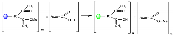 where
where  are hydrocarbons and heterocyclic compounds before neutralization;
  are hydrocarbons and heterocyclic compounds after neutralization.
are hydrocarbons and heterocyclic compounds before neutralization; are hydrocarbons and heterocyclic compounds after neutralization.Thus, when neutralizing the crude oil-contaminated soil, heavy oil fractions can be subjected to chemical degradation with the formation of low-toxic hydrocarbons.
3.5. Stabilized Soils
In order to study the possibility of the use of the neutralized soil in road construction, nine mixtures of stabilized soil were considered (Table 7). As can be seen, the first three mixtures contained 60% of crushed stone, 15% of sand, and 25% of neutralized soil. Their Portland cement content was 6%, 7%, and 8%, respectively. They also contained different amounts of humectant. The other six mixtures did not contain sand. In the second and third triple of mixes, the content of crushed stone and the neutralized soil was 50%, 50%, and 30%, 70%, respectively. The content of Portland cement was equal to 9%, 10%, and 11%.
Table 7.
Composition of the stabilized soil mixes.
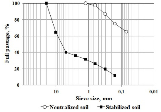
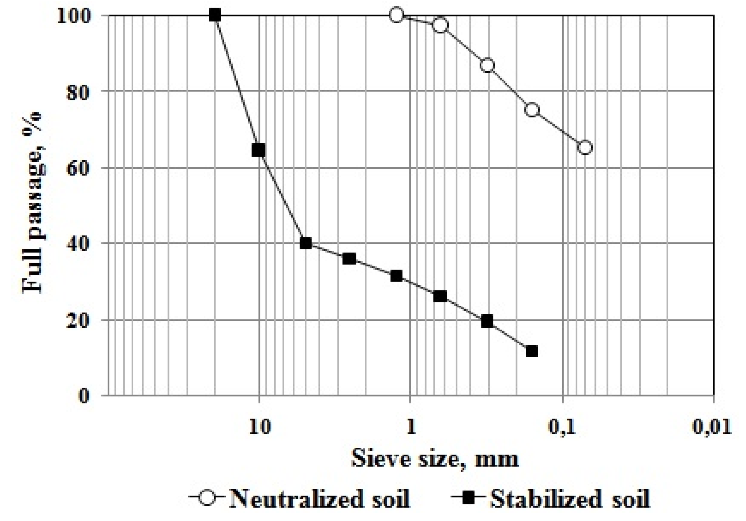
For visual reference, the granulometric curves of the neutralized soil and one of the stabilized soil mixes are represented in Figure 7.
Figure 7.
Granulometric curves for the neutralized soil and the stabilized soil.
Engineering characteristics of the stabilized soils are given in Table 8, from which it can be clearly seen that all strength indicators are increased with the increase of crushed stone and Portland cement content in the mixtures. As expected, compression strength is decreased in all cases as the number of freeze and thaw cycles is increased. The reduction in strength after 10, 15, and 25 cycles of freezing and thawing is, on average, 16%, 38%, and 53%, respectively.
Table 8.
Characteristics of the stabilized soil mixes.
According to the regulatory document [35], all public roads in the Republic of Kazakhstan are divided into five categories depending on traffic intensity (Table 9). The higher the road category, the stronger and more durable the materials used for their pavements. At the same time, for the roads of I–IV categories, the surface (first) layer of pavement is arranged from an asphalt concrete. As the multiyear design practice shows, the pavement of a IIIcategory road has two layers of asphalt concrete with a total thickness of 10 to 12 cm, and roads of I and IIcategories have three layers of asphalt concrete with a total thickness of 15 to 18 cm.
Table 9.
Categories of automobile roads.
Stabilized soils on roads of the I–IV category roads can be used as a base layer material and a subbase layer material, and on V category roads as a pavement material [36].
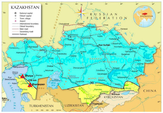
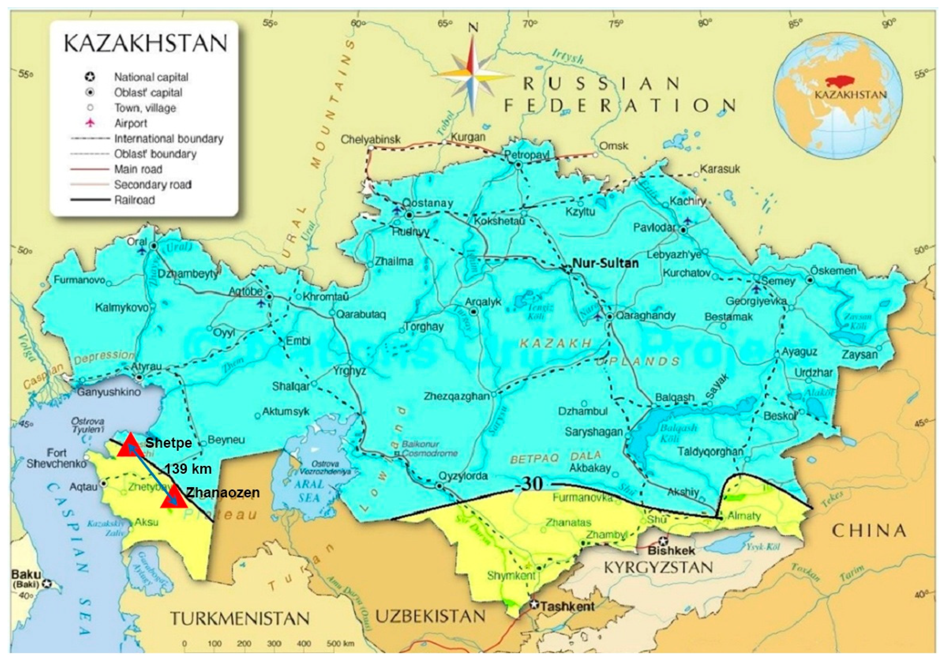
Table 10 shows the conditions for the use of the stabilized soils with the neutralized soil of different compositions. Figure 8 shows a map of the isoline of the minimal temperature of −30 °C on the territory of Kazakhstan. A joint analysis of these tables and the maps shows that the stabilized soil containing 70% of the neutralized soil and 9–10% of Portland cement cannot be used in road construction in Kazakhstan. The stabilized soils of all other compositions can be used as a material of the base layer for pavements. At the same time, only the stabilized soils of I-1 and I-2 (60% crushed stone, 15% sand, 25% neutralized soil, and 7–8% of Portland cement) can be used for roads of the III, IV, and V categories and all others can only be used for roads of the IV and V categories. According to climatic requirements, only mixtures of I-1 and I-3 are allowed to be used in the areas with minimum temperatures below −30 °C, and the remaining mixtures can only be used up to −30 °C.
Table 10.
Conditions for the use of the stabilized soils with the neutralized soil.
Figure 8.
Map of the minimum temperature of−30 °C on the territory of Kazakhstan.
3.6. Experimental Section
An important stage in the implementation of new materials and technologies into road construction is the construction of an experimental section. The possibility for the implementation of the proposed technologies and materials was checked during the construction of an experimental section.
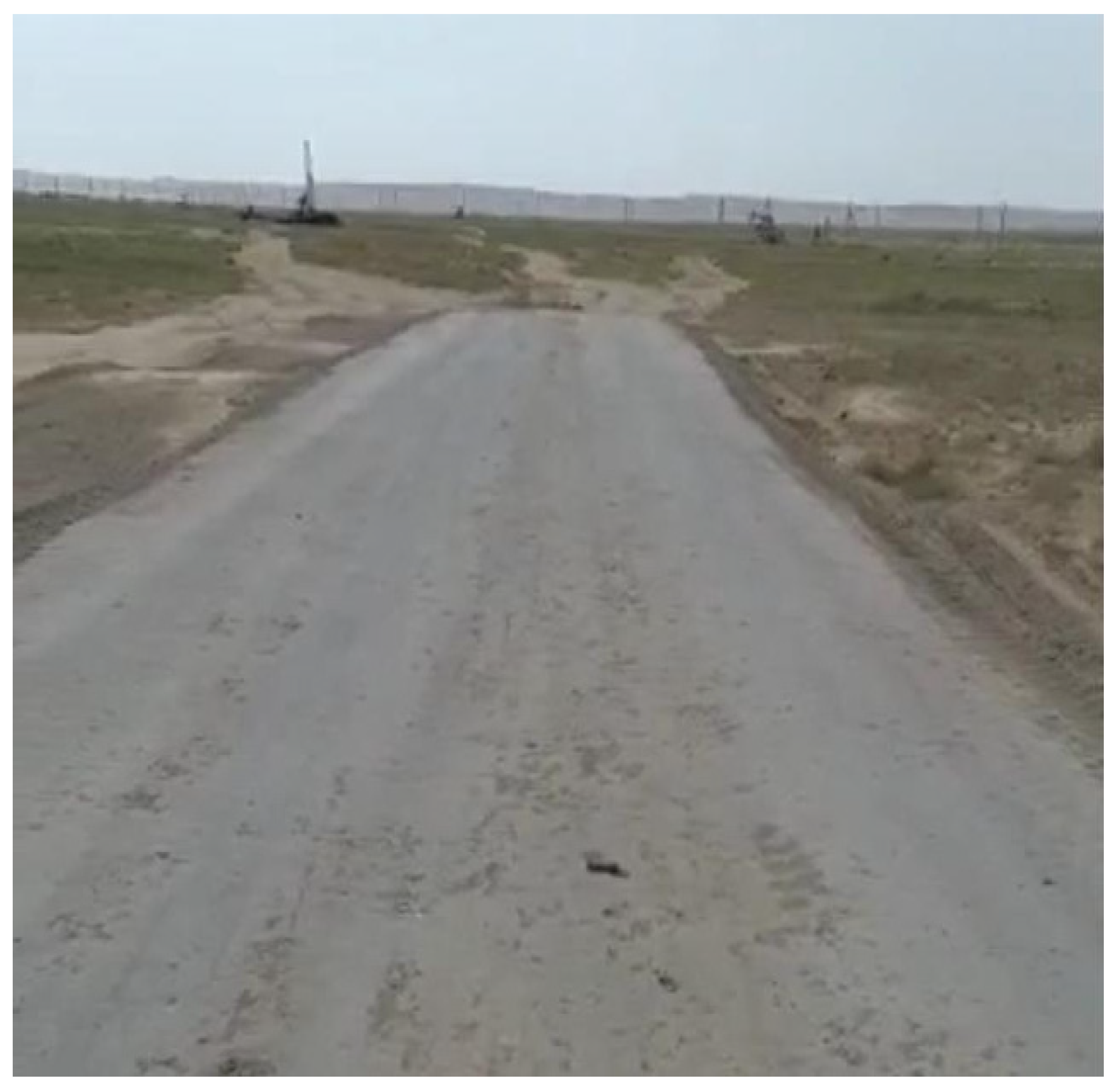
In November 2014, near the city of Zhanaozen (Mangistau region), an experimental road section was built using the stabilized soil with the neutralized soil. The test section had a length of 75 m and a pavement with a width of 3.5 m made from the stabilized soil. The stabilized soil had the following composition: crushed stone 5–20 mm fraction (50%), neutralized soil (40%), Portland cement of M 400 grade (10%), and water with humectant (12%).
Crushed stone was supplied from the “Shetpe” quarry and the neutralized soil from a storage site of the JSC “Ozenmunaigas”. The “Shetpe” quarry is located near Shetpe village, which is 139 km away from Zhanaozen city.
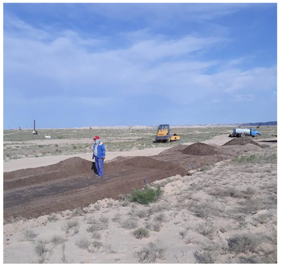
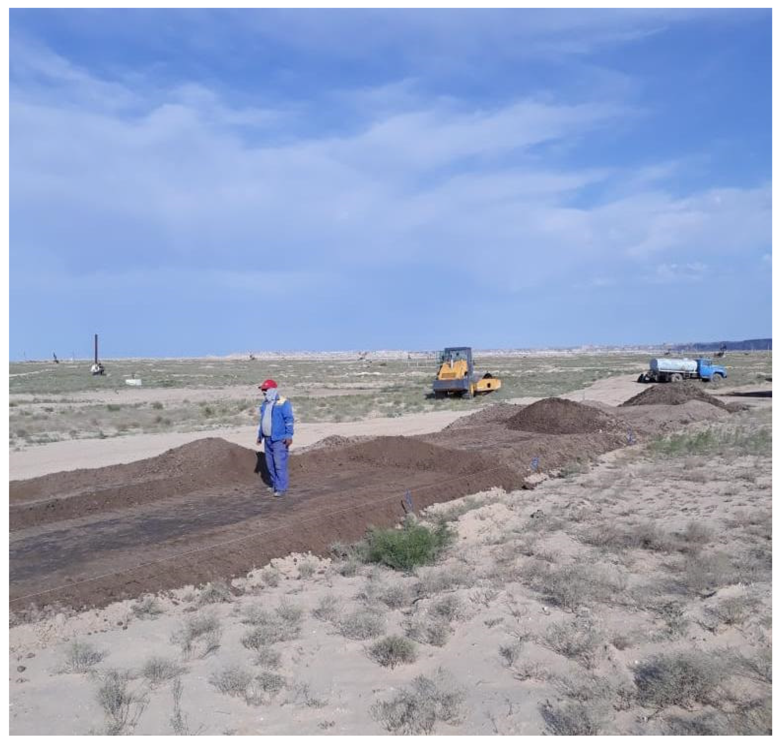
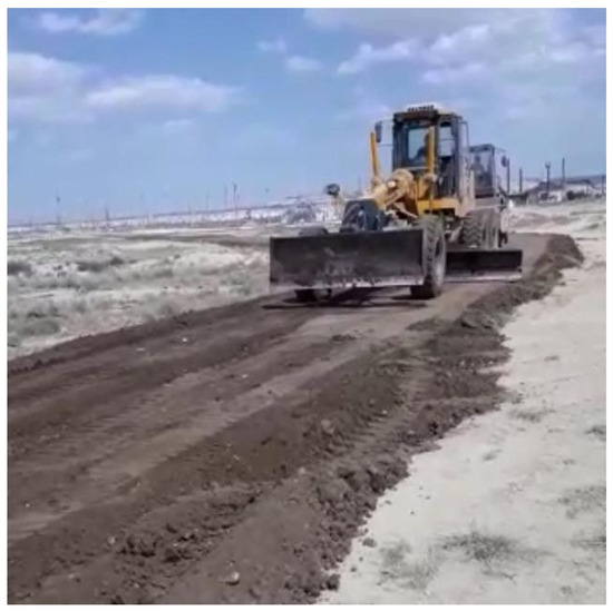
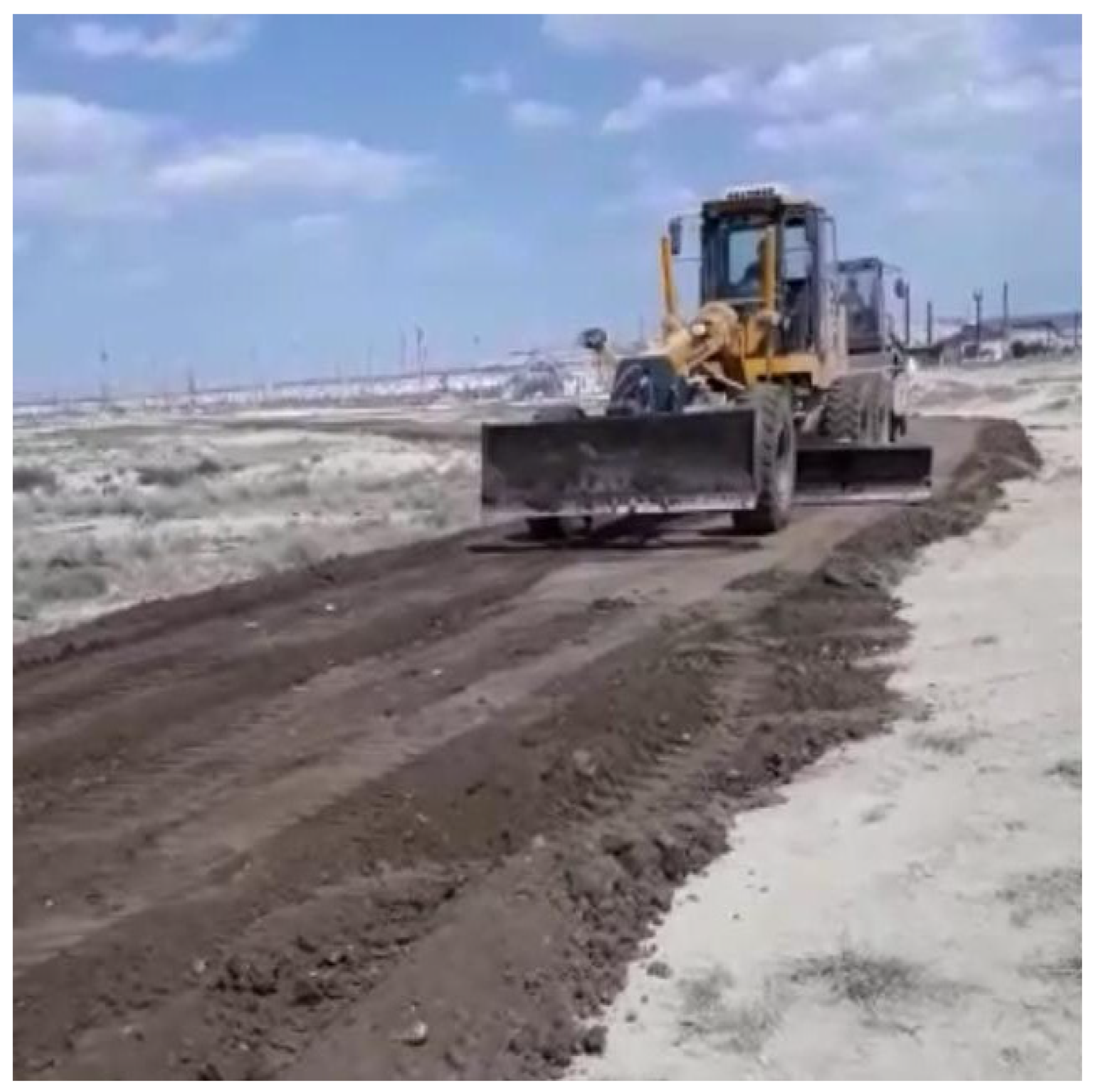
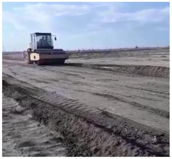
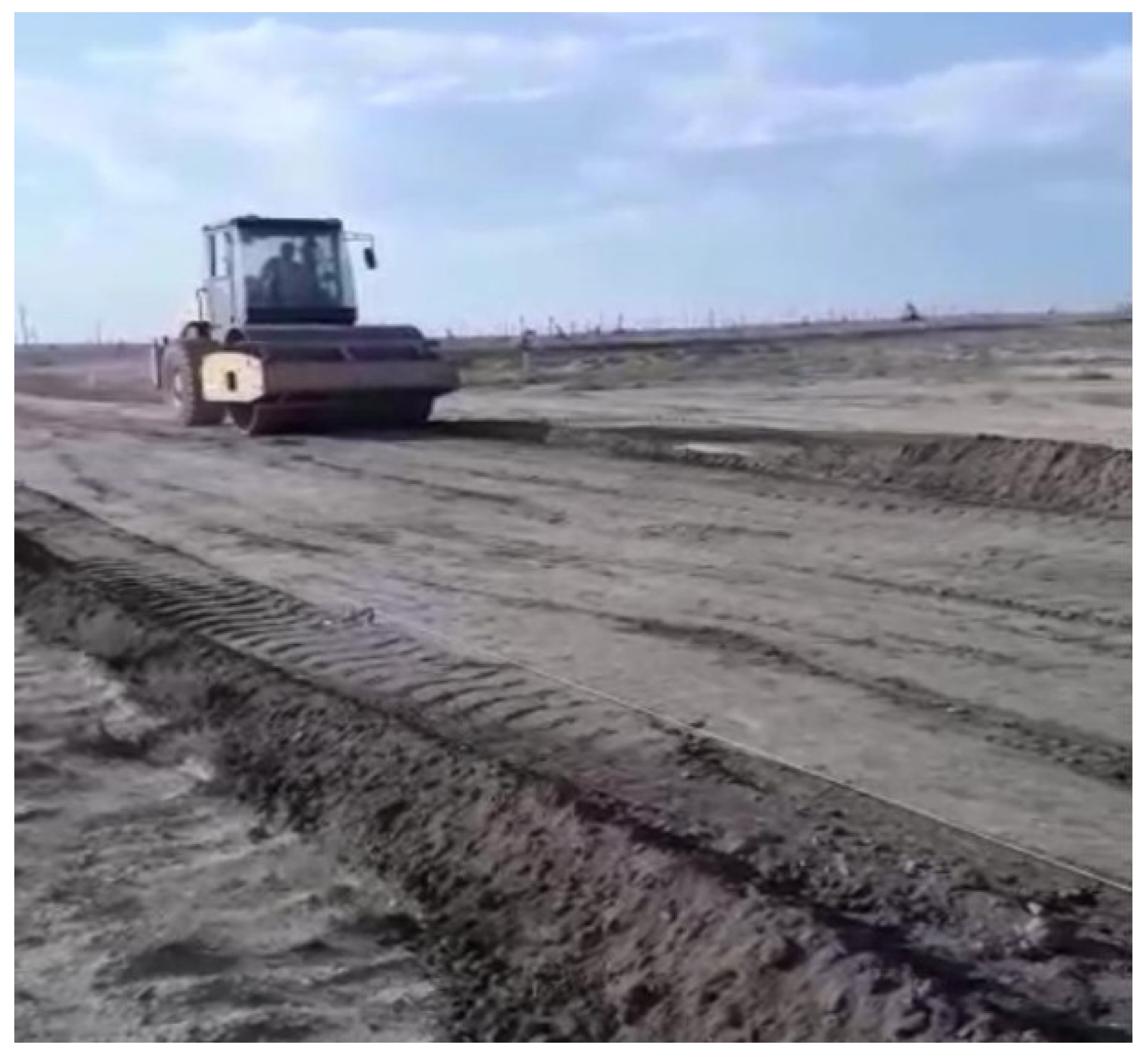
The technology for the construction of the pavement was implemented in the following sequence: the mixing of the crushed stone, the neutralized soil, and Portland cement was performed at the storage site; the mixture of crushed stone, neutralized soil and Portland cement was brought to the experimental section and distributed on the surface of the subgrade (Figure 9); water with humectant was distributed by a highway tank truck produced by the Kamsk automobile plant (tank volume was 16 m3); mixing of the mixture and water on the surface of the subgrade was performed by a grader (Figure 10); pavement material—graded mixture of the stabilized soil with the neutralized soil—was compacted by a smooth drum roller, produced by Rascat (Ural automobile plant, 3 tons; Figure 11).
Figure 9.
Mixture of crushed stone, neutralized soil, and Portland cement on the surface of subgrade.
Figure 10.
Leveling of the stabilized soil layer.
Figure 11.
Compaction of the stabilized soil layer.
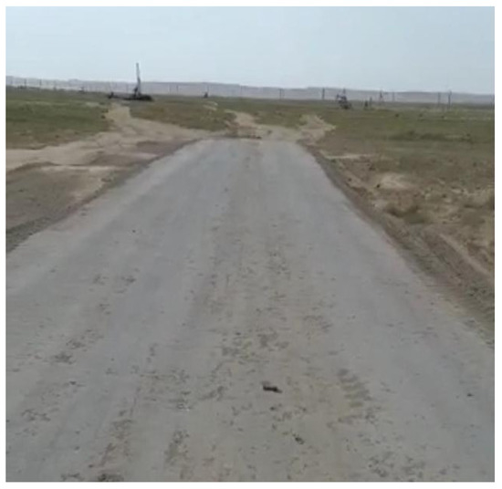
As a result of the subsequent implementation of the above technology, a 15-cm thick pavement was built (Figure 12).
Figure 12.
The completed pavement from the stabilized soil.
Successful implementation of the project in the experimental section showed the full possibility for the use of the neutralized soil in road construction. Meanwhile, conventional machinery and road equipment wereused for transportation, mixing, leveling, and compaction.
4. Conclusions
From this study the following conclusions can be drawn on the basis of the obtained results on the neutralization of the crude oil-contaminated soil and the test of the possibility for the use of the neutralized soil in road construction:
1. A method is proposed for neutralizing of crude oil-contaminated soil using a neutralizer based on humic substances. Schemes were developed for the neutralization of crude oil-contaminated soil in laboratory and production conditions. It is found that the maximal possible degree of neutralization (100%) is achievable at weight ratios of 1:0.1:0.3 for the crude oil-contaminated soil, neutralizer and water, and at the temperature of 80 °C and treatment duration of 15–20 min.
2. When neutralizing the crude oil-contaminated soil, the low-boiling-point hydrocarbon fractions (C12–C17) disappear completely, the high-boiling-point hydrocarbon fractions (C20–C23) essentially increase, andthe content of oil components and metals, including toxic ones, decrease.In other words, the neutralization process reduces the toxicitysignificantly.
3. Laboratory experiments evaluated the engineering characteristics for nine mixtures of stabilized soil with neutralized soil and determined the conditions for their use in road construction (road category, the characteristic layer of pavement, minimal air temperature).
4. An experimental road section was built using the stabilized soil with the neutralized soil (40%). The successful implementation of this project has shown the full possibility for the use of the neutralized soil in road construction.
Author Contributions
Y.E., U.D., G.N., A.S., and K.K. performed experimental research for neutralization of crude oil-contaminated soil; B.T., G.I., and N.Y. performed experimental research forthedetermination of engineering characteristics for stabilized soil mixes with neutralized soil. All of them took part in the writing of the paper.All authors have read and agreed to the published version of the manuscript.
Funding
Grant No. 1234-223 dated 5 May 2017 was received from JSC “Ozenmunaigas” in support of our research work.
Acknowledgments
Authors acknowledge that JSC “Ozenmunaigas” supplied crude oil-contaminated soil for the research and enabled us to construct the experimental road section.
Conflicts of Interest
The authors declare no conflict of interest.
References
- Valeyev, R. Environment Protection and Recording of Wastes at the Enterprises; OKO-Holding: Moscow, Russia, 2004. [Google Scholar]
- Mukhamediyanova, A.; Nigmatullin, R.; Telyashev, E. Investigation of possibility for the use of paraffin deposits as a raw material for paraffin-wax composition. Petrol. Process. Petrochem. 1994, 10, 21–22. [Google Scholar]
- Roy, A.; Baruah, R.; Borah, M.; Singh, A.; Boruah, H.; Saikia, N.; Deka, M.; Dutta, N.; Bora, T. Bioremediation potential of native hydrocarbon degrading bacterial strains in crude oil contaminated soil under microcosm study. Int. Biodeter. Biodegrad. 2014, 94, 79–89. [Google Scholar] [CrossRef] [Scilit]
- Shen, W.; Zhu, N.; Cui, J.; Wang, H.; Dang, Z.; Wu, P.; Luo, Y.; Shi, C. Ecotoxicity monitoring and bioindicator screening of oil-contaminated soil during bioremediation. Ecotoxicol. Environ. Saf. 2016, 124, 120–128. [Google Scholar] [CrossRef] [Scilit]
- Mrozik, A.; Piotrowska-Seget, Z.; Labuzek, S. Bacterial degradation and Bioremediation of Polycyclic Aromatic Hydrocarbons. Polish J. Environ. Stud. 2003, 1, 15–25. [Google Scholar]
- Li, X.; Li, P.; Lin, X.; Zhang, C.; Li, Q.; Gong, Z. Biodegradation of aged polycyclic aromatic hydrocarbons (PAHs) by microbial consortia in slurry and soil phases. J. Hazard. Mater. 2008, 150, 21–26. [Google Scholar] [CrossRef] [Scilit]
- Merkl, N.; Schultze-Kraft, R.; Infante, C. Phytoremediation in the topics-Influence of heavy crude oil on root morphological characteristics of graminoids. Environ. Pollut. 2005, 138, 86–91. [Google Scholar] [CrossRef] [Scilit]
- Moubasher, H.; Hegazy, A.; Moustafa, Y.; Kabiel, H.; Hamad, A. Phytoremediation of soils polluted with crude petroleum oil using Bassiascoparia and its associated rhizosphere microorganisms. Int. Biodeter. Biodegrad. 2015, 98, 113–120. [Google Scholar] [CrossRef] [Scilit]
- Usman, M.; Faure, P.; Hanna, K.; Abdelmoula, M.; Ruby, C. Application of magnetite catalyzed chemical oxidation (Fenton-like and persulfate) for the remediation of oil hydrocarbon contamination. Fuel 2012, 96, 270–276. [Google Scholar] [CrossRef] [Scilit]
- Li, X.; Du, Y.; Wu, G.; Li, Z.; Li, H.; Sui, H. Solvent extraction for heavy crude oil removal from contaminated soils. Chemosphere 2012, 88, 245–249. [Google Scholar] [CrossRef] [Scilit] [PubMed]
- Al-Marzouli, A.; Zekri, A.; Jobe, B.; Dowaider, A. Supercritical fluid extraction for elimination of optimum oil recovery conditions. J. Petrol. Sci. Eng. 2007, 55, 37–47. [Google Scholar] [CrossRef] [Scilit]
- Islam, M.; Jo, Y. Remediation of PAHs contaminated soil by extraction using subcritical water. J. Ind. Eng. Chem. 2012, 18, 1689–1693. [Google Scholar] [CrossRef] [Scilit]
- Wang, M.; Zhang, B.; Li, G.; Wu, T.; Sun, D. Efficient remediation of crude oil-contaminated soil using a solvent/surfactant system. RSC Adv. 2019, 9, 2402–2411. [Google Scholar] [CrossRef] [Scilit]
- Gescha, E.; Harjani, J.; Liang, C.; Ghoshouni, Z.; Andrea, T.; Brown, R.; Jessop, P. Switchable anioni surfactant for the remediation of oil-contaminated sand by soil washing. RSC Adv. 2014, 4, 4638–4645. [Google Scholar]
- Marchenko, L.; Belogolov, E.; Marchenko, A.; Bugaets, O.; Bokovikova, T. Feasibility study of sorption clearing the soil contamination liquidation. Sci. J. Kuban State Agrar. Univ. 2012, 84, 1–10. [Google Scholar]
- Merkotun, I.; Sokolova, Y.; Magomedov, R.; Filimonov, A.; Darjaniya, A. The use of sorbents of natural origin. Eng. Bul. Don. 2017, 4, 1–7. [Google Scholar]
- Taki, G.; Islam, M.; Park, S.-J.; Park, J.-H. Optimization of operating parameters to remove and recover crude oil from contaminated soil using subcritical water extraction process. Environ. Eng. Res. 2018, 23, 175–180. [Google Scholar] [CrossRef] [Scilit]
- Li, D.; Zhang, Y.; Quan, X.; Zhao, Y. Microwave thermal remediation of crude oil contaminated soil enhanced by carbon fiber. J. Environ. Sci. 2009, 21, 1290–1295. [Google Scholar] [CrossRef] [Scilit]
- Hu, G.; Li, J.; Thring, R.; Arocena, J. Ultrasonic oil recovery and salt removal from refinery tank bottom sludge. J. Environ. Sci. Health A 2014, 49, 1425–1435. [Google Scholar] [CrossRef] [Scilit] [PubMed]
- Kapustin, V.; Gureyev, A. Petroleum Processing Technology; Kolos: Moscow, Russia, 2008. [Google Scholar]
- Yagafarova, G.; Leontiyeva, S.; Safarov, A.; Yagafarov, I. Modern Methods for Oil Slime Processing; Khimiya: Moscow, Russia, 2010. [Google Scholar]
- PND F 16.1.38-02. Methods for Measurements of Part by Weight for Petrochemicals in Soil Probes by Capillary Gas-Liquid Chromatography; Federal State-Funded Institution: Moscow, Russia, 2002. [Google Scholar]
- PND F 16.1.21-98. Methods for Measurements of Part by Weight for Petrochemicals in Probes by Fluorimetry on a Liquid Analyzer “Fluorat02”, NPF “Lumex”; L23. Lumex Ltd.: Moscow, Russia, 1998. [Google Scholar]
- CV 5.18.19.01-2005. Methods for Measurements of Content for Elements in Solid Objects by Spectrometry with Inductively Coupled Plasma, NTF “Chromos”; Chromos: Moscow, Russia, 2005. [Google Scholar]
- PND F16.1:2.2:2.3:3.36-2002. Methods for Measurements of Gross for Cadmium, Cobalt, Marganese, Cuprum, Nickel, Chrome and Zinc in Soils, Bed Deposits, Sewage Sludges and Wastes by Flame Atomic-Adsorption spectrometry, FBU “FCAO”; Fox Chapel Area Online: Moscow, Russia, 2002. [Google Scholar]
- PND F 16.1.42-04. Methods for Measurements of Part by Weight for Metals and Metal Oxides in Powder Probes by X-ray-Fluorescent Analysis, LLC “NPO Spectron”; NPO Spectron LTD: Moscow, Russia, 2004. [Google Scholar]
- ST RK 1273-2004. Soils, Methods for Laboratory Determination of Grain (Granularmetric) Composition; Issuu: Astana, Kazakhstan, 2004. [Google Scholar]
- ST RK 1280-2004. Soils, Method for Determination of Organic Substances at Incineration; Issuu: Astana, Kazakhstan, 2004. [Google Scholar]
- ST RK 1218-2003. Materials on the Basis of Organic Binders for Road and Airfield Construction, Test Methods; Issuu: Astana, Kazakhstan, 2003. [Google Scholar]
- GOST 10060-2012. Concretes, Methods for Determination of Frost Resistance; Standardinform: Moscow, Russia, 2014. [Google Scholar]
- ST RK 973-2015. Stone Materials and Soils Treated with Inorganic Binders for Road and Airfield Construction; Specifications: Astana, Kazakhstan, 2015. [Google Scholar]
- Bellami, L. The Infrared Spectra of Complex Molecule; Springer: Berlin/Heidelberg, Germany, 1980. [Google Scholar]
- Silverstein, R.; Webstern, F.; Kiembe, D. Spectrometric Identification of Organic Compounds; John Wiley & Sons: New York, NY, USA, 2005. [Google Scholar]
- Orlov, L.; Grishina, L. Practical Course on Humus Chemistry; MSU: Moscow, Russia, 1981. [Google Scholar]
- CP RK 3.03-101-2013. Automobile roads, Astana, Kazakhstan, 2015. Available online: https://online.zakon.kz/document/?doc_id=38726150 (accessed on 1 March 2020).
- CP RK 3.03-104-2014. Designing of Flexible Pavements; umex Ltd.: Astana, Kazakhstan, 2015; Available online: https://igis.kz/images/snip/stroitelnye-normativy/sp-rk-3.03-104-2014-proektirovanie-dorozhnyx-odezhd-nezhestkogo-tipa.pdf (accessed on 1 March 2020).

© 2020 by the authors. Licensee MDPI, Basel, Switzerland. This article is an open access article distributed under the terms and conditions of the Creative Commons Attribution (CC BY) license (http://creativecommons.org/licenses/by/4.0/).