


Abstract
Conventional flux-reversal permanent magnet motors have problems such as excessive torque ripple and rich harmonic content in direct drive applications such as oil exploration, which restrict their application in high-precision scenarios. To address this issue, this paper presents a hybrid excitation topology that integrates double-armature windings, stator Halbach hybrid permanent magnet arrays, rotor-staggered unequal-tooth and rotor-hybrid permanent magnets. Two-dimensional finite element analysis was conducted using ANSYS Maxwell 2023 R1 to evaluate electromagnetic performance under rated steady-state conditions, rated power 300 kW, rated speed 83 rpm, rated voltage 660 V, rated phase current 307 A, and axial core length 200 mm. The simulation results show that the proposed topology has an average output torque of 34.5 kN·m at rated conditions compared with the traditional flux-to-reverse permanent magnet motor of the same size, and the torque ripple rate is reduced from 27.5% to 17.4%, a relative reduction of 36.8%. The results are based only on numerical simulation and have not been verified by physical prototype experiments. Dynamic control strategies, multi-load transient responses and experimental verification will be carried out in subsequent work.
1. Introduction
The permanent magnets and armature windings of the flux-reverse permanent magnet motor are both placed on the stator, and the rotor is composed of only stacked silicon steel sheets. Due to its simple and robust structure and no excitation loss, it has the advantages of high reliability and high power. It has the potential to be used in direct-drive low-speed high-torque applications such as oil pumping units in oil fields and mining machinery [1,2]. However, traditional FRPMM has significant torque quality flaws: measured torque ripple rates are typically as high as 25–35%, which is much higher than the 5–10% level of permanent magnet synchronous motors; cogging torque can reach 3% to 8% of the rated torque, resulting in low-speed crawling and positioning jitter; and the air gap magnetic field is rich in harmonics, causing vibration noise and additional iron loss. These problems severely restrict the application of FRPMM in high-precision, low-noise scenarios.
For torque ripple suppression in FRPMM, existing research mainly focuses on three dimensions: structural optimization, magnetic circuit design, and control strategy, but a multi-technology collaborative system solution has not yet been formed. In the dimension of structural optimization, Zheng et al. [3] proposed a double-armature winding structure that reduces torque ripple by approximately 15% through differential control, but did not optimize the rotor tooth profile, and the suppression of air gap harmonics was still insufficient; Zhang et al. [4] adopted a dual-rotor structure to enhance power density, but the manufacturing complexity was high and it was not optimized for cogging torque; the staggered unequal-tooth rotor structure effectively reduced the cogging torque by changing the air gap permeability distribution [5], but was not combined with winding optimization, resulting in poor controllability. In the magnetic circuit design dimension, Xu et al. [6,7] designed a hybrid magnetic circuit structure that significantly enhanced the anti-demagnetization ability, but did not quantitatively evaluate the improvement effect on torque ripple; Li et al. [8] used a double-sided permanent magnet layout to increase torque density, but did not introduce the Halbach array, and the air-gap magnetic field harmonics were still significant; The Halbach permanent magnet array improved the air gap waveform through the “single-sided magnetic field” effect [9], but had limited suppression effect on torque ripple when used alone. In the control strategy dimension, existing studies have mostly focused on current harmonic injection or vector control optimization, which can suppress torque ripple to some extent, but are limited by the motor body structure, with limited room for improvement.
Particularly notable is the initial exploration of the application of double-armature windings and Halbach arrays in FRPMM. Zheng [3] verified the boosting effect of double-armature windings on torque density, but did not involve rotor structure optimization; Zhang et al. [4] applied double-armatures to linear FRPMM, also without considering tooth profile modulation; Li et al. [7] analyzed the electromagnetic characteristics of the double-armature FRPMM, but with an equal-tooth rotor and a conventional permanent magnet layout. In the case of the Halbach array, Li et al. [10] applied it to a double permanent magnet vernier motor to improve the air gap waveform, but did not combine it with the double-armature structure and did not introduce the hybrid permanent magnets.
Notably, Zheng et al. [11] further integrated dual-armature windings with Halbach array magnets into a flux-reversal permanent magnet machine, and verified that the combination can improve torque density and suppress partial torque ripple through finite element analysis. However, this work adopted a uniform-tooth rotor structure with conventional single-type permanent magnets, and did not introduce rotor excitation or staggered unequal tooth topology; the harmonic cancellation mechanism under multi-structure coupling was not systematically revealed, and the quantitative decomposition of independent and synergistic effects of each structural feature was not involved.
Existing studies indicate that both double-armature windings and Halbach arrays have the potential to improve FRPMM performance. However, the composite integration of dual-armature windings, Halbach hybrid permanent magnet arrays, staggered unequal-tooth rotors, and rotor hybrid excitation, as well as the synergistic modulation mechanism among the four structures, have not been systematically reported. The independent contribution of each structural feature and the coupling gain under multi-physics interaction still lack quantitative analytical models and theoretical guidance.
Based on the above analysis, there are three common limitations in the existing studies: First, the studies only optimize for a single dimension in structure, magnetic circuit, or control, without considering the multi-physics coupling effect; Second, technologies such as double-armature windings with rotor tooth profiles, Halbach arrays with hybrid permanent magnets have not been organically integrated, and there is a lack of synergistic modulation mechanisms; Third, the independent contribution of each technology to torque ripple and the synergistic gain have not been quantified, and the design lacks theoretical guidance. More crucially, the following core technical problems remain unsolved: the harmonic phase matching conditions when the double-armature winding and the staggered unequal-tooth rotor work together are unknown, making it impossible to predict what tooth width ratio and winding configuration will achieve the optimal harmonic cancellation; The combined magnetic field modulation mechanism of the Halbach array and the hybrid permanent magnet (NdFeB + Alnico) is unclear, especially how the differences in magnetic properties of the two permanent magnets affect the stability of the air gap waveform when the temperature changes; There is a lack of an analytical model for the interaction between rotor excitation and stator permanent magnetic fields, making it difficult to achieve flexible control of “magnetization-demagnetization”. These gaps leave the existing design at the stage of empirical trial and error, unable to theoretically guide the co-optimization of multiple structural parameters.
These research gaps lead to a core scientific question: How can deep suppression of torque ripple be achieved through multi-structure co-modulation while maintaining the torque density advantage of FRPMM? The key to the problem lies in: (1) establishing a unified electromagnetic analytical model that takes into account double-armature windings, Halbach hybrid permanent magnets, rotor excitation, and staggered unequal teeth to reveal the coupling law of multi-source magnetic emf; (2) Clarify the modulation mechanism of the interlaced unequal teeth on the air gap permeability and the phase matching conditions with the harmonics of the double-armature winding, and theoretically predict the harmonic cancellation effect; (3) Quantify the independent contribution and synergistic gain of each structure to the torque ripple to provide a theoretical basis for the design. Solving this problem is expected to break through the performance bottleneck of existing single-dimensional optimizations and provide new approaches for high-performance design of FRPMM.
Based on this, this paper aims to explore a multi-structure-coordinated FRPMM topology that integrates double-armature windings, stator Halbach hybrid permanent magnet arrays, rotor staggered unequal teeth, and rotor hybrid permanent magnets to improve torque quality through coupling modulation of multi-source magnetic fields. The main work of this paper includes the following: (1) establishing a unified electromagnetic analytical model that takes into account the above four structures; (2) revealing the mechanism of multi-structure coordinated air-gap magnetic field modulation and torque-harmonic cancellation conditions; and (3) evaluating the torque ripple suppression effect of the topology at rated conditions (300 kW, 83 rpm) through two-dimensional finite element analysis and make a quantitative comparison with traditional FRPMM. It should be noted that this paper focuses on electromagnetic design and steady-state performance analysis, and dynamic control strategy, thermal behavior and experimental verification will be carried out in subsequent work.
2. Motor Topology and Working Principle
2.1. Overall Structure
The flux-reverse permanent magnet motor proposed in this paper uses a 24-slot/14-tooth pole-slot fit, which is an optimal solution based on the field modulation theory and torque performance analysis. The overall structure of the motor, as shown in Figure 1, is mainly composed of the stator, rotor and air gap. The stator is in the form of double-armature windings, with winding slots and non-winding slots arranged in sequence among 24 stator slots. Surface-mounted Halbach-array permanent magnets are installed at both ends of the stator slot openings, using a mixture of alnico and neodymium iron boron. The rotor features an interlaced unequal tooth structure consisting of seven fundamental enhancement teeth and seven harmonic suppression teeth, with one harmonic suppression tooth between every two fundamental enhancement teeth. The fundamental enhancement teeth and harmonic suppression teeth are arranged alternately to form the rotor slots, in which the armature windings are installed in one number. The parameters of the motor are shown in Table 1.
Figure 1.
A schematic diagram showing the cross-sectional structure of a flux-reversal permanent magnet motor, including the stator, rotor, armature winding, permanent magnet and air gap.
Table 1.
Simulated motor data of the proposed design.
2.2. Reverse-Flux Mechanism
The basic working principle of the motor in this study still follows the reverse-flux pattern. As shown in Figure 2a, the permanent magnets at the slots of the double-armature windings of the stator are magnetized in the same direction. As shown in Figure 2b, when the rotor rotates, the salient pole structure consisting of 7 fundamental enhancement teeth and 7 harmonic suppression teeth periodically changes the air gap permeability corresponding to the stator teeth beneath it. In the absence of excitation current, the magnetic fields generated by the permanent magnets on the stator and rotor produce time-varying magnetic linkages in the stator winding as the rotor rotates, that is, the flux-reverse effect. The mathematical model is [12], where is the fundamental magnetic flux linkage of the permanent magnet. The rotating magnetic potential formed by the sinusoidal current flowing through the stator winding, which varies with the position of the rotor, interacts with the combined magnetic field modulated by the permanent magnets and the rotor teeth to form a constant electromagnetic torque.
Figure 2.
A schematic diagram showing the magnetization mode and method of the cross-section of the flux-reversal motor structure, mainly highlighting the connection mode of the stator winding and the rotor winding. (a) Magnetization mode; (b) working principle diagram of the magnetization method.
2.3. Description of Each Structure and Function
2.3.1. Halbach Arrays Interact with Hybrid Permanent Magnets
The arrangement of Halbach type permanent magnets on both sides of the stator slot enables the magnetic field lines to be effectively directed to the air gap side, reducing the leakage magnetic flux along the stator tooth yoke, thereby increasing the effective magnetic flux density of the air gap and making the air gap magnetic field waveform closer to sine, which is conducive to reducing torque pulsation. Both the stator and rotor adopt a hybrid permanent magnet structure of alnico and neodymium iron boron, aiming to use the high residual magnetism of neodymium iron boron to provide the main magnetic field strength to ensure high torque, and the excellent temperature stability and anti-demagnetization ability of alnico to act as a magnetic anchor to stabilize the magnetic field when the motor temperature rises, improving high-temperature working performance and reliability.
In this design, the permanent magnets on both sides of each double stator winding slot opening are surface-attached and identical, while the permanent magnets under adjacent stator slot openings are different. As shown in Figure 3, the spatial harmonic content of the magnetic field in the alternating magnetic field distribution is enhanced compared with the conventional permanent magnet arrangement in the next row. NdFeB35 was mixed with Alnico9 in this paper. Measured parameters: NdFeB35 residual magnetism 1.2 T, coercive force 875 kA/m, temperature coefficient −0.11%/°C; Alnico9 residual magnetism 1.15 T, coercive force 95 kA/m, temperature coefficient −0.02%/°C. At a temperature rise of 60 °C, the magnetic density of pure NdFeB decreased by 6.6%, while that of the hybrid structure decreased by only 2.3%.
Figure 3.
A comparison diagram of two arrangements of hybrid permanent magnets is presented.
2.3.2. Synergy Between the Double-Armature Winding and the Rotor Winding
The stator double-armature windings can have a certain phase difference in space, and a current with a phase difference can be carried in time [13]. This design offers a variety of control possibilities. For example, a current with a specific phase difference can be fed in to generate the main torque with the torque winding and the compensating torque with the compensating winding to counteract the cogging torque or a specific harmonic torque, thereby achieving fine suppression of torque ripple [14].
The rotor armature winding upgrades the motor from a permanent magnet motor to a hybrid excitation motor. As shown in Figure 4b, direct current can be supplied to the rotor winding at low speed and high torque. Compared with Figure 4a, an auxiliary magnetic field in the same direction as the permanent magnet magnetic field can be generated to achieve “magnetic field enhancement”, thereby increasing the peak torque. When operating at high speed, a reverse direct current can be applied to generate a magnetic field opposite to that of the permanent magnet to achieve “demagnetization”, thereby expanding the constant power operating area. The ability to regulate the flexible magnetic field is difficult for traditional permanent magnet motors.
Figure 4.
A comparison diagram of the structure between the salient-pole rotor and the induction armature rotor, including the salient-pole rotor and the rotor winding. (a) Traditional salient pole structure and (b) induced armature structure.
2.3.3. The Function of Staggered Unequal Teeth and Empty Slots
The rotor adopts a structure of 7 fundamental enhancement teeth +7 harmonic suppression teeth. The fundamental enhancement teeth are responsible for increasing the torque output, and the harmonic suppression teeth are responsible for optimizing the harmonic spectrum of the air-gap magnetomotive force. The two work together to achieve comprehensive optimization of motor performance. As shown in Figure 5a, by designing the size ratio and distribution of the staggered unequal teeth, the amplitude of the working harmonics is enhanced compared to the same teeth in Figure 5b, thereby increasing the average torque; At the same time, the adverse harmonic components that cause torque ripple are suppressed, that is, the harmonic spectral characteristics of the air-gap magnetomotive force are improved.
Figure 5.
Comparison of rotor tooth profile difference structures: (a) schematic diagram of rotor staggered unequal teeth; (b) schematic diagram of rotor equal teeth. Note: The bottom slot spacing for (a) is 24 mm, and for (b) is 28 mm; all other unmarked dimensions remain unchanged.
In contrast, tangential permanent magnets (such as outward-flipped poles) may have advantages in specific operating conditions (such as reducing inductance), but their magnetic flux distribution is usually more uniform and prone to causing magnetic chain asymmetry, which can introduce stronger magnetic field harmonics. The Halbach array is chosen to maximize the utilization efficiency of magnetic flux, enhance the torque density, and achieve more efficient magnetic flux modulation through the orderly guidance of magnetic flux in combination with unequal teeth on the rotor, while maintaining a compact rotor structure.
The interlaced unequal tooth structure mainly functions as a “flux amplifier” in flux-reversal permanent magnet motors, designed to counteract the flux-weakening effect caused by the fundamental flux reversal of the permanent magnets. Specifically, the fundamental flux density generated by the permanent magnets in the air gap typically changes direction periodically with the rotor position (i.e., flux reversal), which leads to a reduction in the average value of the fundamental flux density in the air gap and limits the fundamental torque density of the motor [15]. Unequal teeth achieve spatial modulation of the fundamental flux density generated by the permanent magnets by altering the relative position or width of the rotor teeth, causing the air gap width to vary periodically with the rotor position (i.e., generating a modulation wave in the air gap magnetic conductance). This modulation mechanism utilizes the flux modulation principle to reshape the spatial distribution of the fundamental flux density of the permanent magnets and, through appropriate phase matching, to cancel or enhance the fundamental component, ultimately achieving an increase in the fundamental flux density and the fundamental torque [16]. This modulation effect mainly targets the permanent magnet excitation and amplifies the beneficial flux by optimizing the magnetic circuit structure while suppressing the adverse flux.
2.3.4. Empty Slots and Flux Modulation
The open slot is the most fundamental flux modulation element in the stator structure of permanent magnet motors, with its core function being to suppress the cogging torque caused by the armature current. The stator in this paper alternates between semi-closed slots and open slots: the large slots are open slots that accommodate the double-armature windings; the small slots are semi-closed slots with no windings. The open slot effectively reduces the harmonic flux density amplitude generated by the armature reaction by physically breaking the air gap flux. The semi-closed slot maintains a higher mechanical strength of the teeth while reducing the slot leakage flux. The alternating arrangement of the two slots creates periodic changes in magnetic permeability, which, together with the staggered unequal teeth of the rotor, enhance the modulation effect of the air-gap magnetic field. Specifically, when the armature current flows through the coils at the stator slot openings, the Ampere’s law dictates that the magnetic field it generates in the air gap is in the same direction as that of the permanent magnets, introducing additional harmonic flux components and causing significant spatial fluctuations in the air gap flux density. The open slot effectively reduces the amplitude of the harmonic flux density generated by the armature by physically interrupting the air gap flux, thereby significantly suppressing the torque ripple and back EMF waveform distortion caused by the cogging effect [17,18]. This modulation mechanism is achieved through the spatially non-uniform distribution of the air gap width and belongs to a negative feedback modulation of the armature excitation [19].
2.4. Summary of the Synergistic Mechanism
The four structures are not simply superimposed, but synergy is formed through electromagnetic coupling. Specifically, the double-armature windings provide a controllable harmonic current source whose phase and amplitude can be adjusted independently. The Halbach array optimizes the fundamental magnetic field waveform generated by the permanent magnet, reducing the inherent harmonic content. The staggered unequal teeth provide a spatially modulated period related to the rotor position, causing the air gap permeability to change periodically. Hybrid permanent magnets ensure magnetic field stability over a wide temperature range. Four through air-gap magnetoconductor coupling: double-armature harmonic currents interact with interleaved unequal tooth modulated magnetoconductors to produce additional harmonics of specific order. The fundamental optimization of the Halbach array reduces the number of harmonics that need to be cancelled. The temperature stability of the hybrid permanent magnet ensures that the synergistic effect is maintained throughout the entire operating temperature range. Ultimately, by designing a matching relationship between the phase difference of the double-armature and the offset angle of the unequal teeth, specific order harmonics are counterbalanced. The mathematical description of this synergistic mechanism will be derived in detail in Section 3.
3. Mathematical Model
3.1. Stator Double-Armature Winding Magnetomotive Force
The spatial magnetomotive force distribution of a single set of concentrated windings follows the cosine law. When higher harmonics are ignored, the static magnetomotive force expression is
In Equation (1), is the static magnetomotive force of the stator torque winding, is the number of turns of the stator torque winding, is the current of the stator torque winding, is the number of pole pairs of the stator torque winding, and is the spatial angle.
When a sinusoidal alternating current is fed through the windings, introducing the time-phase term, the dynamic magnetomotive force of a single set of windings becomes
In Equation (2), is the amplitude of the current in the stator torque winding, is the electric angular velocity of the current in the stator torque winding, and is the time.
The stator is a double-armature winding, and the two sets of windings are powered independently. The total magnetomotive force is the superposition of the magnetomotive forces of the two sets of windings, resulting in the formula
In Equation (3), is the number of turns of the stator compensating winding, is the current of the stator compensating winding, is the number of pole pairs of the stator compensating winding, is the current of the stator torque winding and the electric angular velocity.
3.2. Stator Halbach Hybrid Permanent Magnet Magnetomotive Force
Halbach array hybrid permanent magnets (alternating AlNiCo and NdFeB) are surfacing on both sides of the large slot openings of the stator. The magnetomotive force generated by a single surface-mounted permanent magnet is cosine distributed along the circumferential space of the stator as
In Equation (4), is the amplitude of the magnetic emf of a single permanent magnet, and is the number of pole pairs of the permanent magnet.
The materials of the adjacent large slot openings of the permanent magnets alternate, the magnetic emf directions of the two permanent magnets are opposite, the phase difference is ; therefore, the magnetic emf of the neodymium iron boron permanent magnet is
In Equation (5), is the magnetomotive force of the neodymium iron boron permanent magnet.
Two permanent magnets are alternately and uniformly arranged along the circumference of the stator and superimposed to obtain the total magnetic emf of the stator Halbach hybrid permanent magnet, which is
In Equation (6), is the total magnetic potential of the stator Halbach hybrid permanent magnet, and is the magnetic potential of the alnico permanent magnet.
3.3. Rotor Interleaved Unequal-Tooth Air Gap Permeability
The design principle of the rotor staggered unequal tooth structure is based on the magnetic reluctance modulation effect. When the rotor rotates, the staggered unequal teeth alternately pass through the stator teeth, causing the air gap magnetic reluctance to change periodically, essentially introducing a new periodicity into the air gap magnetic permeability [20,21,22].
Based on the fundamental principles of the magnetic circuit, it is derived that the air gap permeability is inversely proportional to the air-gap length. The rotor staggered unequal tooth structure causes the air gap length to change periodically with the rotor space angle . The expression is
In Equation (7), is the average air gap length, is the fluctuation amplitude of the air gap length, = 14 is the total number of teeth of the rotor (7 fundamental enhancement teeth +7 harmonic suppression teeth).
Air gap permeability ( for vacuum permeability), substitute the air gap length expression and perform Fourier series expansion on it, preserving the fundamental and lower harmonics.
In Equation (8), is the air gap permeability, is the average permeability, and , is the amplitudes of each harmonic permeability.
The periodic expression of the air gap permeability is given as
3.4. Comprehensive Derivation of Multi-Topologically Coupled Magnetoemf
The previous sections respectively describe the independent mechanisms of action of double-armature windings, Halbach hybrid permanent magnets, rotor windings, and staggered unequal teeth. This section establishes the joint expression of the four-source magnetomotive force and reveals its coupling modulation law.
3.4.1. Four-Source Joint Expression
The stator side synthetic magnetomotive force is formed by the superposition of the double-armature winding magnetomotive force and the Halbach hybrid permanent magnet magnetomotive force. Combining Equations (3) and (6), considering the spatial phase relationship, the total magnetomotive force on the stator side is
where
It is the combined amplitude of the NTH harmonic on the stator side, is the equivalent phase angle, and ω = 2πf is the electrical angular frequency.
The rotor-side synthetic magnetomotive force is generated by the rotor winding and the mixed permanent magnets built into the rotor. Let the mechanical angular velocity of the rotor be Ω, then the rotor position angle , the total magnetic emf on the rotor side is
Here, is the combined amplitude of the NTH harmonic on the rotor side, and is the initial phase angle. For synchronous operation .
The total synthetic magnetomotive force in the air gap is the vector sum of the stator side and the rotor side:
When unfolded, we get
Using the cosine superposition formula, the effective amplitude of the NTH harmonic is
Here, is the spatial phase difference of the NTH harmonic between the stator and rotor.
3.4.2. Phase Matching and Harmonic Cancellation Conditions
Torque ripple is mainly caused by the interaction between the harmonics of the stator and rotor magnetic potentials and the harmonics of the air gap magnetic conductance. Substituting the magnetic permeability expansion shown in Equation 9 into the Ohm law of the magnetic circuit , the NTH harmonic component of the air gap magnetic flux density is
where Zr = 14 is the number of rotor teeth and is the MTH harmonic amplitude of magnetic permeability. The first term in the formula is the direct action term, and the last two terms are the magnetic permeability modulation terms.
Torque ripple suppression requires the dominant harmonic components to cancel each other out. For 5th and 7th torque harmonics, the phase matching condition is .
This condition is achieved by designing the width ratio and relative position of the staggered unequal teeth so that the 5th and 7th harmonic magnetic fields of the stator and rotor are out of phase, thereby weakening each other in the air gap.
3.5. Air Gap Synthetic Magnetic Density
The air gap synthetic magnetic density is determined by both the total magnetic potential and the air gap magnetic permeability, following Ohm’s law of magnetic circuits. The core relationship is that the air gap synthetic flux density is equal to the product of the total magnetic potential and the air gap permeability:
Expand the permeability to the 7th harmonic (the higher harmonics contribute less than 2% to the torque ripple and are ignored):
The amplitudes of each harmonic’s magnetic permeability are
In the formula , is the fundamental enhancement tooth width, is the harmonic suppression tooth width, is the average air gap length, and is the MTH harmonic modulation amplitude. The relative amplitudes of each magnetic permeability harmonic are shown in Table 2.
Table 2.
The relative amplitudes of each magnetic permeability harmonic.
As shown in Table 2, the amplitudes of the 3rd and above harmonics decay rapidly, and the 7th harmonic is only 2.6% of the fundamental, verifying the rationality of retaining it to the 7th.
The complete expression of the air gap flux density is
where (m = 0 is the direct term, m ≠ 0 is the modulation term). Frequency and phase are determined by rotational speed and initial alignment.
The dominant torque harmonics satisfy the magnetic field modulation conditions: and ,
where p = 7 is the number of pole pairs. For the topology of this paper, the working harmonics are n = 1, m = 0 (fundamental torque), and the main pulsation sources are n = 5, m = 1 and n = 7, m = 1, suppressed by phase-matching conditions.
3.6. Winding Flux Linkage and Counter Electromotive Force
According to the definition of flux linkage, a winding flux linkage is the product of the air gap flux density passing through the effective area of the winding and the number of turns of the winding , that is , its flux is .
Here, is the micro-area element.
The effective length of the motor is , the air gap radius is , the number of turns of the winding along the spatial distribution function is , the air gap flux density is , the integral range covers the entire circumference of the stator (), substituting to obtain the stator winding flux linkage expression:
Therefore, the expression of the back electromotive force is . The derivation process of the rotor winding flux linkage is consistent with that of the back electromotive force, and only the stator-related parameters need to be replaced with rotor parameters [23,24].
3.7. Total Electromagnetic Torque
The flux-reverse permanent magnet motor is a double excitation, double-armature structure, and the total electromagnetic torque is the superposition of permanent magnet torque, reluctance torque, and double winding interaction torque, which is
In Equation (22), is the total electromagnetic torque of the motor, is the permanent magnet torque, is the reluctance torque, is the alternating torque of the stator and rotor windings.
The permanent magnet torque is produced by the interaction of the stator and rotor permanent magnets with the corresponding armature winding currents respectively, and the expression is
In Equation (23), is the stator permanent magnet flux link, is the angle between the stator winding current and the stator permanent magnet flux link, is the rotor permanent magnet flux link, is the angle between the rotor winding current and the rotor permanent magnet flux link.
The reluctance torque is produced by the difference in inductance between the straight shaft and the alternating shaft of the motor, and is expressed as
In Equation (24), is the direct shaft inductance of the motor, is the alternating shaft inductance of the motor, is the direct shaft component of the stator current, is the alternating shaft component of the stator current.
There is mutual inductance between the two armature windings of the stator and rotor, and the mutual inductance interacts with the current of the two sets of windings to produce alternating torque, which is expressed as
In Equation (25), is the mutual inductance between the stator and rotor windings.
The total electromagnetic torque equation is obtained by superimposing the three parts of torque, which is
4. Simulation Analysis and Verification
4.1. Finite Element Model Establishment
The two-dimensional transient electromagnetic field solver of ANSYS Maxwell 2023 R1 is adopted for simulation. The detailed modeling and solution settings are described as follows.
4.1.1. Geometric Model and Material Parameters
The motor adopts a 24-slot/14-tooth pole-slot fit, and the main dimensional parameters are consistent with Table 1.
Stator and rotor cores: DW315-10 non-oriented electrical steel. The nonlinear B-H curve and loss parameters are imported from the official Ansys material library: saturation magnetic density 1.95 T, lamination coefficient 0.95. Iron loss is calculated by the Bertotti formula, with hysteresis coefficient kh = 185 W/m3, eddy current coefficient kc = 0.65 W/m3, excess loss coefficient ke = 0.02 W/m3.
Permanent magnets: NdFeB35 and AlNiCo9. Temperature-dependent properties are set: NdFeB35 has remanence 1.2 T, coercivity 875 kA/m, remanence temperature coefficient −0.11%/°C at 20 °C; AlNiCo9 has remanence 1.15 T, coercivity 95 kA/m, remanence temperature coefficient −0.02%/°C at 20 °C.
4.1.2. Mesh Settings and Independence Verification
Triangular adaptive mesh is adopted for the whole solution domain, with local refinement in key regions. Air gap region: four-layer mapped mesh, characteristic element size 0.3 mm, to accurately capture air gap magnetic density variation; permanent magnet region: characteristic element size 1 mm, refined at magnet corners; stator and rotor core: characteristic element size 3 mm, locally refined at tooth tips.
Mesh independence is verified with average torque as the evaluation index. When the total number of elements increases from 38,000 to 72,000, the relative deviation of average torque is less than 0.5%. The final model adopts a scheme with about 65,000 elements, balancing accuracy and computational efficiency.
4.1.3. Boundary Conditions and Solution Settings
Boundary condition: The outer stator boundary is set as Dirichlet boundary (vector magnetic potential A = 0). No periodic symmetry is used, and the full cross-section model is simulated to avoid boundary errors caused by the unequal tooth structure.
Time step: 0.1 ms, corresponding to a rotor angular increment of about 0.5 electrical degrees at 83 rpm rated speed.
Simulation duration: 3 complete electrical periods after the torque reaches steady state, and data from the last stable period is used for performance calculation.
Convergence criterion: The relative error of magnetic potential between adjacent iterations is less than 0.1%.
4.1.4. Excitation Settings
Stator double-armature windings: Symmetrical three-phase sinusoidal current with 120° phase difference, rated RMS phase current 307 A. The two sets of windings have a 180° electrical phase difference to match the flux reversal effect, with 1:1 current distribution and equal turns.
Rotor excitation winding: DC current of 15 A, with direction consistent with the magnetization direction of rotor permanent magnets under rated flux-enhancement condition.
4.1.5. Performance Calculation Method
Average torque: Arithmetic mean of the steady-state torque waveform over one electrical period.
Torque ripple amplitude: Difference between maximum and minimum torque values over one steady-state period.
Torque ripple rate: The calculation procedure is strictly unified for both the proposed motor and the reference motor to ensure comparability and traceability. The instantaneous torque waveform is extracted after the simulation enters a fully steady state, excluding the start-up transient segment. The data of one complete electrical period are taken, with a total of 120 uniform sampling points corresponding to a time step of 0.1 ms. The arithmetic mean of all sampling points in the period as the average torque Tavg is calculated. The maximum value Tmax and minimum value Tmin of the torque waveform in the same period is extracted. The torque ripple rate is calculated by the formula .
Iron loss: Calculated by the built-in iron loss model of Maxwell, including hysteresis loss, eddy current loss and excess loss.
Efficiency: , where copper loss Pcu is calculated by I2R considering winding resistance at operating temperature.
4.2. No-Load Characteristic Analysis
4.2.1. Magnetic Field Lines and Magnetic Density Distribution
The position of the permanent magnets in the motor and the direction of the magnetic field can be seen in Figure 6. On both sides of each large slot on the stator side are attached Helbeck array permanent magnets, and the adjacent slots are respectively alnico permanent magnets and neodymium iron boron permanent magnets, with alternating magnetic field polarities. The magnetic field lines start from the N pole of the permanent magnet on one side of the stator, pass through the air gap into the rotor, pass through the rotor core composed of seven fundamental wave strengthening teeth and seven harmonic suppression teeth, and finally return through the air gap to the S pole of the permanent magnet on the other side of the stator, forming a complete closed loop. This path validates the mechanism of flux reversal: as the rotor rotates, the direction of the flux in the cross-linked stator windings will periodically reverse. The six alternating permanent magnets embedded in the fundamental reinforcing teeth of the rotor further modulate the magnetic field, as shown in Figure 6, the resulting local auxiliary magnetic circuit.
Figure 6.
Diagram showing the distribution of magnetic field lines in the cross-sectional structure of the motor.
The magnetic density cloud diagram shown in Figure 7 was obtained based on the two-dimensional finite element analysis of Ansys Electronics Desktop 2023 R1, showing the spatial distribution of magnetic flux density of the motor under rated speed 83 rpm and rated load conditions, with simulation time t = 0 ms and rotor position 102.86°. Under this condition, the stator double-armature windings are fed with a rated current (phase current RMS 307 A), and the rotor windings are fed with direct current excitation current to enhance the magnetic field. The magnetic density cloud diagram quantitatively presents the spatial distribution of magnetic flux amplitudes: the high magnetic density areas are represented from yellowish green to yellowish orange, up to 3.085 T, mainly concentrated on the surface of the permanent magnets at the tips and slots of the stator teeth, corresponding to the areas with dense magnetic field lines, indicating that the permanent magnetic field is highly concentrated here.
Figure 7.
Diagram showing the magnetic flux density cloud distribution of the cross-sectional structure of the motor.
It should be noted that the extreme value of 3.085 T occurs on the surface of the permanent magnet at the interface between the magnet and the air gap/stator tooth tip, rather than inside the permanent magnet bulk or the silicon steel core. This local peak is caused by the flux concentration effect of the Halbach array, which gathers magnetic flux toward the air gap side, and it belongs to surface leakage flux aggregation rather than the working flux density inside the permanent magnet material. Under rated operating conditions, the actual magnetic flux density inside the NdFeB35 bulk ranges from 0.8 T to 1.1 T, and that inside AlNiCo9 ranges from 0.7 T to 1.0 T, both within the normal working range of the corresponding materials.
To evaluate the demagnetization risk, the operating points of the permanent magnets are further checked based on the official material demagnetization curves. At room temperature (20 °C), both types of permanent magnets operate in the linear segment of the demagnetization curve, and the minimum operating point is far above the knee point, with no risk of irreversible demagnetization. Under the extreme high-temperature condition of 150 °C, the minimum operating point of NdFeB35 still remains above the knee point of the demagnetization curve, satisfying the safety criterion of less than 5% irreversible demagnetization rate. The flux concentration effect on the magnet surface is the designed target to improve air gap flux density, and it does not introduce additional demagnetization risk, since demagnetization is dominated by the reverse magnetic field from armature reaction rather than the self-concentrated surface flux density of the magnet itself
The actual core magnetic density of the stator tip is approximately 1.6–1.8 T. Most areas of the stator yoke and rotor core show medium-to-low magnetic density (dark blue, below 1.0 T), far below the saturation magnetic density of DW315-10 silicon steel sheets, about 1.95 T, indicating that there is no local saturation in the magnetic circuit and the material utilization is appropriate. Notably, the tooth magnetic density corresponding to the large slots with windings, about 1.5–1.8 t, is significantly higher than that of the small slots without windings, about 0.8–1.2 t, which directly reflects the enhanced effect of increasing the size of the double winding slots on the concentrated flux. Overall, the combination of the stator and rotor slots with the hybrid permanent magnets effectively achieves magnetic field modulation, laying the foundation for generating smooth electromagnetic torque.
4.2.2. Air Gap Flux Density
As shown in Figure 8, the air gap flux density distribution curve shows a smooth sinusoidal waveform, which is in line with the magnetic field theory of permanent magnet synchronous motors. The total harmonic distortion (THD) of the air gap flux density waveform is 8.7%, with the 3rd harmonic amplitude of 0.062 T, the 5th harmonic of 0.041 T, and the 7th harmonic of 0.028 T, verifying good sinusoidal characteristics. The peak occurs at the polarity surface of the permanent magnet, and the zero point is at the neutral surface, verifying the principle of flux conservation (the areas of the positive and negative half cycles are equal, and there is no overall flux leakage). Based on this ideal curve, we can evaluate the integrity of the motor’s magnetic circuit and the smoothness of commutation. If the actual operating waveform has sharp peaks or troughs, it indicates that the cogging effect has not been completely suppressed, and the current smooth distribution provides an effective error reference for manufacturing and assembly. To compensate for the reduced magnetic permeability caused by the wide air gap, the motor is designed to increase the magnetization intensity of the magnetic circuit to counteract the negative impact of the air gap. The rotor and stator cores are constructed using high-permeability silicon steel sheets DW315-10 to maximize the “concentration” of magnetic flux. High-energy-product permanent magnets (a mixture of NdFeB35 and Alnico9) are used, and despite the wide air gap, the magnetic field strength generated by the permanent magnets themselves is very large. The flux guidance effect of the Halbach array is utilized to “compress” the flux to the air gap side, preventing flux leakage to the back iron side, thereby increasing the flux density on the air gap side. Moreover, under conditions of low air gap flux density, the motor compensates for the insufficient magnetic field strength by increasing the stator current to generate sufficient electromagnetic torque. A high pole pair number design is adopted, which, although increasing the motor’s polarity, also distributes the magnetic flux demand per pole. Through the combined effect of these physical mechanisms, the motor can maintain the closure of the magnetic field and the generation of electromagnetic torque even under design parameters with a large air gap width and low flux density, thus achieving stable operation.
Figure 8.
Air gap flux density distribution curve.
4.2.3. Induced Electromotive Force
As shown in Figure 9, the waveforms of the back electromotive force of the double-armature winding measured at the rated speed of 83 r/min under no-load conditions are presented. The two sets of windings present the same amplitude, with a peak of approximately 185 V and a voltage constant Ke = 1.578 V/rpm, but with opposite phases and 180° electrical angle offset, which directly verifies the principle of flux inversion. Due to the alternating polarity arrangement of the permanent magnets in the adjacent stator slots, the effective flux links in the two sets of windings change in opposite directions as the rotor rotates, thereby inducing reverse electromotive force. The result shows that the magnetic circuit is symmetrical, the air gap is relatively uniform, and the magnetic field distribution is balanced in both positive and negative directions.
Figure 9.
Waveform of induced electromotive force in the positive and negative windings of the stator under double-rotor excitation.
As seen from Figure 10, to achieve the ideal three-phase balance, the amplitudes of the three curves are exactly equal, and the phases are strictly 120° different from each other. According to Faraday’s law of electromagnetic induction, the back electromotive force of the winding is the negative derivative of the flux linkage with respect to time.
Figure 10.
Schematic diagram of the back electromotive force waveform of the flux-reversal motor.
4.3. Load Performance Analysis
Armature Current
Under load conditions, as shown in Figure 11, the current waveform applied to the stator double-armature windings experiences a transient response of approximately 80 ms at the moment of sudden load increase, during which the current rises from zero and suppresses the DC bias and attenuates the oscillation. Then the current quickly enters A steady state, presenting as a balanced and symmetrical sinusoidal waveform with equal three-phase amplitudes and a peak of about 434 A, corresponding to the rated design value of 307 A phase current. The slight deviation of about 1% in simulation is caused by the numerical error of the transient solver, which is within the acceptable range of engineering accuracy. It should be noted that the transient process shown is the natural electromagnetic response of the motor under step current excitation, without closed-loop controller or inverter model. This paper focuses on steady-state electromagnetic performance under rated conditions, and detailed closed-loop dynamic control strategies will be carried out in subsequent work.
Figure 11.
Current waveform diagram under the load of double-armature windings, including phases A, B, and C.
4.4. Model Validation
The analytical predictions of key parameters under rated working conditions and the comparison with the finite element results are shown in Table 3.
Table 3.
The analytical predictions of key parameters under rated working conditions and the comparison with the finite element results.
The fundamental quantity error is less than 5%, and the harmonic quantity error is approximately 9%, meeting the engineering prediction accuracy requirements. The sources of error include the analytical model ignoring core saturation, two-dimensional field-effect approximation, and truncation of harmonics above the 7th order.
4.5. Multi-Condition Performance Analysis
4.5.1. Load Variations
Performance variations under each load condition are shown in Table 4.
Table 4.
Performance variations under each load condition.
4.5.2. Speed Variation
Changes in performance at each rotational speed are shown in Table 5.
Table 5.
Changes in performance at each rotational speed.
The 150 rpm operating point falls into the flux-weakening region, where the output torque decreases proportionally with the increase in rotational speed.
4.6. Quantitative Comparison with Conventional Motors
4.6.1. Reference Motor Specifications
The conventional flux-reversal permanent magnet motor is selected as the reference for performance comparison. To ensure the fairness and traceability of the comparison, the reference motor adopts exactly the same stator outer diameter, rotor inner diameter, axial core length, core material grade and total permanent magnet volume as the proposed motor. The specific configuration of the reference motor is single-armature concentrated winding, equal-tooth rotor with 25.5° uniformly distributed pitch, surface-mounted radially magnetized NdFeB35, no Halbach array, no hybrid permanent magnet, and no rotor winding. The full parameter comparison between the reference motor and the proposed motor is listed in Table 6.
Table 6.
Full parameter comparison of the reference and proposed motors.
The torque ripple rate is uniformly calculated by based on the steady-state torque waveform of one electrical period for both motors. Figure 12. shows torque waveform diagram of a traditional flux-reversal motor.
Figure 12.
Torque waveform diagram of a traditional flux-reversal motor.
4.6.2. Comparison of Torque Waveforms
The traditional motor has a pulsation rate of 27.5% and an amplitude of 9.49 kN·m.
Figure 13 shows the output torque transient response waveform of the motor under rated load conditions. As shown in Figure 13, the output torque experiences a start-up transient within an initial approximately 7 ms, rising rapidly from 0 to the rated steady-state value. In the steady-state phase, the average output torque is 34.5 kN·m, showing obvious periodic pulsation, with a torque pulsation amplitude of approximately 6.0 kN·m and a torque pulsation rate of approximately 17.4%. The waveform validates the dynamic torque response characteristics of the motor under rated conditions. It should be noted that the transient process shown is the natural electromagnetic response of the motor under step current excitation, without closed-loop controller or inverter model. This paper focuses on steady-state electromagnetic performance under rated conditions, and detailed closed-loop dynamic control strategies will be carried out in subsequent work. Table 7 shows comparison performance of traditional flux-reverse motor and the proposed motor.
Figure 13.
Torque waveform diagram of the flux-reversal motor in this design.
Table 7.
Comparison performance table of traditional flux-reverse motor and the proposed motor.
4.7. Parameter Sensitivity Analysis: Tooth Width Ratio Effect
To investigate the influence of rotor tooth geometry on torque performance, the total tooth width is fixed, and the width ratio of fundamental enhancement teeth to harmonic suppression teeth is adjusted. The tooth width ratio is defined as , where is the width of the fundamental enhancement tooth and is the width of the harmonic suppression tooth. The quantitative performance results under different α values are listed in Table 8.
Table 8.
Effect of tooth width ratio on motor performance.
The results show that the optimal comprehensive performance is achieved at α = 1.0, i.e., the equal-width staggered design. It should be clarified that the “staggered unequal tooth” topology is defined from the perspective of spatial arrangement and functional differentiation: the two types of teeth are circumferentially staggered with different permeability modulation phases, and undertake the functions of fundamental torque enhancement and harmonic suppression respectively. The tooth width ratio α is an adjustable geometric parameter. When α = 1.0, the two types of teeth have equal width but still maintain staggered spatial arrangement and functional differentiation, which is a special case of the staggered unequal tooth topology. When α deviates from 1.0, the uneven tooth width will introduce additional high-order harmonic components. For example, when α > 1.0, the 7th harmonic flux density increases significantly, which, in turn, increases the torque ripple. Therefore, the equal-width staggered scheme achieves the optimal balance between torque output and ripple suppression.
4.8. Quantification of Each Structure’s Independent Contribution and Synergistic Gains of Each Structure
This section establishes a simplified quantitative assessment framework. The framework compares the benchmark case, four single-structure cases and the full-structure case to quantify the overall synergistic gain beyond the linear superposition of individual independent effects, which ensures logical consistency of the calculation. It should be clarified that this work does not implement a complete full factorial design, since intermediate combination cases required for identifying second-order and higher-order interaction effects are not included. The overall synergistic gain reported here reflects the total non-additive improvement of the full-structure configuration relative to the linear sum of individual effects, rather than a detailed decomposition of each order of interaction. A complete full factorial analysis with all combination cases will be carried out in future work to resolve the detailed interaction mechanisms between structural pairs.
4.8.1. Assessment Framework and Definition of Indicators
Four key structural features are selected as the research objects, where the “−1” state represents the conventional configuration (the structure is absent) and the “+1” state represents the proposed improved configuration (the structure is present). The four structures are as follows:
S1: Double-armature winding;
S2: Stator Halbach hybrid permanent magnet array;
S3: Rotor staggered unequal tooth structure;
S4: Rotor hybrid permanent magnet with excitation winding.
The conventional FRPMM (Case 0, all structures at “−1” state) is taken as the benchmark, consistent with the reference motor in Section 4.6. Four single-structure cases are constructed, each with only one structure at “+1” state and the rest at “−1” state, to measure the pure independent effect of each structure. The full-structure case (Case F, all structures at “+1” state) corresponds to the proposed motor topology.
All cases adopt the same rated phase current and total permanent magnet volume. Through magnetic circuit parameter matching, the average output torque remains basically unchanged, and the optimization is mainly reflected in torque ripple suppression and performance improvement, which ensures the fairness of performance comparison.
Two core indicators are defined.
Independent main effect (ΔMi): The performance change of the single-structure case relative to the benchmark, reflecting the performance improvement brought by the i-th structure acting alone.
Overall synergistic gain (Gsyn): The difference between the actual total performance change of the full-structure model and the sum of the independent main effects of all structures, calculated as where ΔPtotal = Case F − Case 0 is the total performance change of the full-structure model relative to the benchmark. A synergistic gain in the direction of performance optimization indicates that electromagnetic coupling between multiple structures produces additional improvement beyond linear superposition of individual effects.
Regarding the anti-demagnetization temperature indicator, it is defined as the maximum ambient temperature at which the irreversible demagnetization rate of the permanent magnet is less than 5% under rated load. The value is calculated based on the temperature-dependent demagnetization curves of permanent magnet materials combined with magnetic circuit operating point analysis. For the conventional motor with single NdFeB35, the permanent magnet operating point drops to the knee of the demagnetization curve at 120 °C, reaching the 5% irreversible demagnetization criterion. For the proposed motor with hybrid permanent magnets, AlNiCo9 with a lower temperature coefficient acts as a “magnetic anchor”, stabilizing the magnetic circuit operating point at high temperatures, and the critical temperature for 5% irreversible demagnetization is increased to 150 °C. This result is a theoretical calculation based on material parameters and magnetic circuit analysis, and detailed multi-physics coupled simulation of temperature field and electromagnetic demagnetization, as well as experimental verification, will be carried out in the prototype development stage.
4.8.2. Simulation Results of All Assessment Cases
All cases are solved using the ANSYS Maxwell 2023 R1 2D transient solver under rated operating conditions (300 kW, 83 rpm, 660 V). Key performance parameters are listed in Table 9.
Table 9.
Performance parameters of all assessment cases under rated conditions.
4.8.3. Decomposition of Independent Effects and Synergistic Gains
Based on the data in Table 9, the independent main effect of each structure is calculated, as shown in Table 10.
Table 10.
Independent main effects of each structural feature.
The total performance change of the full-structure model relative to the benchmark, the overall synergistic gain, and the proportion of synergistic gain in the total improvement are summarized in Table 11.
Table 11.
Decomposition of total improvement and synergistic gains.
The calculation results satisfy strict mathematical consistency: the sum of independent main effects plus the synergistic gain equals the actual total performance change.
4.8.4. Physical Mechanism of Synergistic Effects
The non-zero synergistic gains originate from the electromagnetic coupling between multiple structures, and the physical mechanisms can be explained from three aspects.
Synergy between double-armature winding and Halbach array (S1 × S2): The Halbach array optimizes the air gap magnetic field waveform, making the spatial distribution of the permanent magnet field closer to sinusoidal and reducing the inherent harmonic content. This provides a more ideal magnetic field basis for the harmonic compensation of the double-armature winding, so that the compensation current can more accurately target the remaining harmonic components. The marginal torque ripple reduction of adding Halbach array on the basis of double-armature winding is greater than the independent effect of Halbach array alone, which constitutes the main source of synergistic gain for back-EMF waveform optimization.
Synergy of double-armature, Halbach array and staggered unequal teeth (S1 × S2 × S3): The staggered unequal tooth structure modulates the spatial distribution of air gap permeability, forming a phase matching relationship with the harmonic magnetic potential of the double-armature winding and the optimized magnetic field of Halbach array. The permeability modulation period of unequal teeth couples with the harmonic period of the armature winding, generating harmonic cancellation effects at specific rotor positions and further suppressing torque ripple beyond the linear superposition of individual structures.
Full-structure thermal–magnetic synergistic effect: The hybrid permanent magnets on both stator and rotor improve the temperature stability of the magnetic field through the “magnetic anchor” effect. At high operating temperatures, the AlNiCo component with a low temperature coefficient stabilizes the magnetic field waveform symmetry of the Halbach array, which indirectly maintains the harmonic compensation accuracy of the double-armature winding and the permeability modulation effect of the unequal teeth. This coupling ensures that the torque quality improvement is maintained over a wide temperature range, resulting in additional synergistic gains in anti-demagnetization capability and comprehensive efficiency.
Future work will further carry out full factorial design with all combination cases to decompose second-order and higher-order interaction effects, and reveal the coupling mechanism between structures more precisely.
5. Future Prospects, Feasibility Optimization and Limitations
Although the structure shows obvious inhibitory effects in the simulation stage, it still faces many challenges in actual engineering.
5.1. Engineering Implementation Challenges
First, the complex unequal-pitch interlaced teeth and double-sided permanent magnet layout pose considerable difficulties for the manufacturing process. After the stator adopts the double-armature winding structure, the tooth width at the large slot openings is significantly reduced, and some stator tooth widths may be only 3 to 5 mm, approaching the minimum blanking width limit of DW315-10 silicon steel sheets. This ultra-thin tooth structure is prone to deformation and warping during lamination production, affecting the core lamination coefficient, and may face the risk of electromagnetic stress concentration when rotating at high speed. It is recommended to consider using laser cutting or electrical discharge machining instead of traditional blanking in actual manufacturing, to partially replace the ultra-thin tooth area with segmented core structure or soft magnetic composite material, and to appropriately optimize the slot shape design to increase the minimum tooth width to more than 4 mm. In addition, assembly errors and pole calibration issues may also offset some of the theoretical advantages. Future research will focus on developing high-precision manufacturing processes and exploring the feasibility of reducing production costs.
Secondly, the adoption of double-armature windings inevitably increases the complexity of the drive system. Compared with the single-inverter system of conventional motors, the dual three-phase inverter scheme increases the number of power semiconductor devices and adds corresponding drive circuits, current sensors and PWM channels. Based on the cost composition of industrial motor drive systems, the overall hardware cost is estimated to increase by 30% to 40% [24]. The control algorithm must take into account the electromagnetic coupling between the two sets of stator windings and between the stator and rotor windings, requiring decoupling compensation and coordinated current control strategies. The increase in the number of current sensors, gate drivers, and pulse width modulation channels also raises the difficulty of implementing the controller. However, these additional costs are partially offset by the increase in torque density and the reduction in torque ripple, where system-level performance improvements are of significant value in high-precision applications such as oilfield extraction equipment that require smooth operation. Subsequent work will explore integrated drive topologies and model predictive control strategies to reduce these complexity costs.
Thirdly, the topology exhibits the best electromagnetic characteristics within a specific speed range, but its heat dissipation and mechanical strength under broadband or extremely high-speed operating conditions have not been rigorously verified. Subsequent work will need to incorporate multi-condition heat dissipation analysis and high-speed mechanical reliability tests.
5.2. Limitations of the Current Study
Simulation dimension approximation: All electromagnetic simulations are based on a two-dimensional transient model, which ignores the end effect of windings, axial magnetic flux leakage, and three-dimensional edge effects of permanent magnets. There is a certain deviation between the two-dimensional simulation results and the actual three-dimensional physical prototype, especially for the calculation of copper loss and end leakage inductance.
Anti-demagnetization performance evaluation: The reported anti-demagnetization temperature is a theoretical calculation value based on the temperature-dependent demagnetization curves of permanent magnet materials and magnetic circuit operating point analysis. No temperature sweep simulation, multi-physics thermal–electromagnetic-coupled demagnetization analysis, or irreversible demagnetization experimental test has been carried out. The actual anti-demagnetization capability under real operating conditions may be different from the theoretical value. The current demagnetization check is based on two-dimensional finite element magnetic circuit analysis, and three-dimensional demagnetization distribution simulation and high-temperature demagnetization experimental verification will be carried out in the prototype test stage.
Scope of dynamic performance analysis: The transient current and torque waveforms presented in the manuscript describe the natural electromagnetic response under open-loop step current excitation, without establishing an inverter model, closed-loop controller, or defined load transient test conditions. This paper focuses on steady-state electromagnetic performance, and systematic dynamic control performance is not within the scope of the current study.
Depth of synergistic effect analysis: The current factorial design only quantifies the overall synergistic gain of the four structures, and does not decompose second-order and higher-order interaction effects between every two or more structures. The coupling mechanism between individual structural pairs still needs to be further resolved through full factorial experiments.
Lack of multi-physics and long-term reliability evaluation: The following practical factors have not been fully quantitatively evaluated and may significantly affect the actual performance of the motor: manufacturing tolerances and assembly accuracy of unequal teeth; variability of magnetic material parameters; thermal behavior under double-winding copper loss superposition; long-term magnetic degradation law of hybrid permanent magnets under thermal cycling and armature reaction; and the fault tolerance mechanism of multi-inverter systems.
Absence of prototype verification: All conclusions and performance indicators in this paper are obtained from two-dimensional finite element numerical simulations, and have not been verified by physical prototype experiments. The actual engineering performance remains to be confirmed by subsequent prototype tests.
5.3. Feasibility Assessment and Optimization Prospects
Regarding feasibility, the current preliminary judgment is based entirely on electromagnetic field theory derivation and finite element simulation results, and has not been independently verified by experimental prototypes. The analytical model suggests that the combination of unequal-pitch interlaced teeth and double-sided permanent magnets can produce a significant magnetic flux cancellation effect, fundamentally weakening the harmonic excitation source. The finite element simulation results are highly consistent with the theoretical derivations, and the data of a 36.8% reduction in torque ripple validates the validity of the design concept. In addition, double-armature windings and Halbach arrays have precedents in existing motor designs, providing a technical reference for the manufacture of this structure. However, it must be emphasized that the above feasibility study is limited to the electromagnetic performance aspect. The actual engineering feasibility, including manufacturing feasibility, thermal management effectiveness, long-term operational reliability, and life cycle cost, all await experimental verification. Overall, the topology shows high research value in terms of theoretical completeness, simulation verification and technical inheritance, providing a potential path for further prototype verification and industrialization exploration rather than an established engineering solution.
By optimizing the width ratio, relative position and phase difference between the fundamental enhancement teeth and the harmonic suppression teeth, the air gap permeability modulation waveform will be closer to the ideal sine wave. The optimization of the fundamental enhancement teeth can further amplify the fundamental flux density generated by the permanent magnet, thereby significantly increasing the peak torque and rated torque density. At the same time, by precisely designing the shape and position of the harmonic suppression teeth, specific higher harmonics that may be introduced by the non-uniform teeth themselves can be offset, further reducing torque ripple and lowering noise and vibration levels.
Subsequent work will focus on the following aspects: sensitivity analysis of key parameters and global optimization of the whole machine; integrated drive topology and model predictive control strategy; multi-physics thermal–electromagnetic–mechanical-coupled analysis and high-speed mechanical reliability assessment; and experimental prototype fabrication and full-performance test verification.
6. Conclusions
This paper presents a multi-structure cooperative FRPMM topology integrating double-armature windings, stator Halbach hybrid permanent magnet array, rotor staggered unequal teeth and rotor hybrid permanent magnets. The core theoretical contribution lies in the establishment of an electromagnetic analytical model that takes into account the unified effects of the four structures, revealing the phase matching conditions between double-armature harmonics and staggered unequal-tooth magnetic permeability modulation, as well as the compound magnetic field modulation mechanism of Halbach array and hybrid permanent magnets, providing a theoretical framework for the multi-parameter cooperative optimization of FRPMM.
The quantitative performance indicators are summarized as follows. Compared with the traditional FRPMM, the proposed topology achieves an average output torque of 34.5 kN·m under rated conditions; the torque ripple amplitude is reduced from 9.49 kN·m to 6.0 kN·m, and the torque ripple rate is reduced from 27.5% to 17.4%, a relative reduction of 36.8%; the total harmonic distortion rate of the back electromotive force is reduced from 12.8% to 8.3%; the efficiency rises from 91.2% to 92.5%. The anti-demagnetization temperature, theoretically estimated based on material demagnetization curves and magnetic circuit operating point analysis, is increased from 120 °C to 150 °C with the hybrid permanent magnet design. The improvements result from multi-structural synergies: double-armature windings provide controllable harmonic compensation degrees of freedom, staggered unequal teeth achieve periodic spatial modulation of air gap permeability, Halbach array optimizes the air gap magnetic field waveform, hybrid permanent magnets enhance thermal stability, and rotor excitation windings expand magnetic field regulation capability.
Engineering limitations include the following: the ultra-thin teeth of the stator are close to the limit of the blanking process, and there is a high risk of laminated deformation; the dual inverter system increases hardware costs by approximately 30% to 40%, and the control algorithm requires decoupling compensation; the superimposition of copper losses in the double windings increases the demand for heat dissipation; and manufacturing tolerances, differences in material temperature coefficients, and long-term magnetic performance degradation have not been evaluated. Furthermore, all conclusions are based only on two-dimensional finite element numerical simulations and have not been verified through physical prototype experiments.
The subsequent work will focus on the following: sensitivity analysis of key parameters and global optimization; integrated drive topology and model predictive control strategy; multi-physics thermal analysis and high-speed mechanical reliability assessment; and experimental prototype fabrication and performance verification. This study provides a theoretical reference and numerical basis for the multi-structure co-design of FRPMM, and its practical engineering application value awaits experimental verification and confirmation.
Author Contributions
Conceptualization, J.H., R.W. and Y.Y.; methodology, J.H.; software, J.H.; validation, J.H.; formal analysis, J.H.; investigation, J.H.; resources, J.H.; data curation, J.H.; writing—original draft preparation, J.H.; writing—review and editing, J.H.; visualization, J.H.; supervision, Y.Y. and R.W.; project administration, Y.Y. and R.W.; funding acquisition, Y.Y. All authors have read and agreed to the published version of the manuscript.
Funding
This work was supported by the Suzhou Key Core Technology Research and Development Project(SNGD202308), and Major Project of Basic Science (Natural Science) Research in Higher Education Institutions in Jiangsu Province (24KJA460009), and Jiangsu Robotics and Intelligent Equipment Engineering Research Center (SuFa Gai Gao Ji Fa [2023] 1026), and in part by Qing Lan Project.
Data Availability Statement
The original contributions presented in this study are included in the article. Further inquiries can be directed to the corresponding author.
Conflicts of Interest
The authors declare no conflicts of interest.
References
- Yan, Y.; Geng, C.; Chen, H.; Gao, Y.; Qu, R.; Shi, T. Improved magnetic flux linkage calculation model for flux-reversal permanent magnet machines based on air-gap filtering effect and stator slotting effect. Proc. Chin. Soc. Electr. Eng. 2025, 45, 8202–8212. [Google Scholar] [CrossRef]
- Chen, M. Research on Linear Machines of New Dual-Armature Winding Flux-Reversal Motors. Master’s Thesis, Southeast University, Nanjing, China, 2022. [Google Scholar]
- Zheng, Y. Electromagnetic Analysis and Topology Study of a New Dual-Armature Flux-Reversal Machine. Ph.D. Dissertation, Zhejiang University, Hangzhou, China, 2021. [Google Scholar]
- Zhang, H.; Liu, M. Research on new dual-armature winding flux-reversal linear machines. Electr. Mach. Control 2021, 41, 456–465. [Google Scholar]
- Xu, L.; Zhu, X.; Liu, L.; Zhang, C.; Liu, H.; Quan, L.; Chen, W. Stator-excited hybrid magnetic circuit design and experimental study of linear-rotary permanent magnet machines. Proc. Chin. Soc. Electr. Eng. 2023, 43, 7683–7694. [Google Scholar]
- Zheng, P.; Zhao, J.; Liu, R.; Tong, C.; Wu, Q. Magnetic Characteristics Investigation of an Axial-Axial Flux Compound-Structure PMSM Used for HEVs. IEEE Trans. Mag. 2010, 46, 2191–2194. [Google Scholar] [CrossRef] [Scilit]
- Liu, H.; Wang, X.; Chen, H.; Bao, J.; Yan, H.; Wang, G.; Gorbounov, Y. Design and Analysis of Modular Transverse Flux Dual-Rotor Switched Reluctance Motor. ACES J. 2025, 40, 863–871. [Google Scholar]
- Li, Y.; Yang, H.; Lin, H.; Liu, W.; Zhao, X. Torque generation mechanism and performance evaluation of a dual-sided PM machine with stator U-shaped magnets. IEEE Trans. Ind. Appl. 2022, 58, 250–260. [Google Scholar] [CrossRef] [Scilit]
- Zhang, C.; Liu, X. Comparative study of electromagnetic performance of double-tooth variable flux memory machine. J. Phys. Conf. Ser. 2020, 1549, 052050. [Google Scholar] [CrossRef] [Scilit]
- Li, H.; Zhu, Z.Q. Influence of adjacent teeth magnet polarities on performance of flux reversal permanent magnet machine. IEEE Trans. Ind. Appl. 2019, 55, 354–365. [Google Scholar] [CrossRef] [Scilit]
- Zheng, L.; Wu, J.; Zhu, Y.; Fang, Y.; Qiu, L. Analysis of dual-armature flux reversal permanent magnet machines with Halbach array magnets. IEEE Trans. Energy Convers. 2021, 36, 3044–3052. [Google Scholar] [CrossRef] [Scilit]
- Vegireddy, G.; Sampathirao, S. Rare-earth-free Al-Ni-Co hybrid PMa-SyRM for an air-conditioner compressor. IET Electr. Power Appl. 2024, 18, 656–667. [Google Scholar] [CrossRef] [Scilit]
- Li, Y.; Jing, L. Analysis and optimization of a novel dual PM Vernier machine with Halbach array. J. Electr. Eng. Technol. 2023, 18, 4159–4167. [Google Scholar] [CrossRef] [Scilit]
- Liu, D.; Wang, H.; Yu, S. High-temperature superconducting dual-stator brushless excited synchronous generator design and analysis. J. Supercond. Nov. Magn. 2025, 33, 1234–1245. [Google Scholar]
- Zhang, Z.; Yu, S.; Feng, Z. Torque ripple suppression in dual-rotor synchronous machines with dual-pole logarithmic coupling. J. Electr. Eng. 2025, 27, 300–310. [Google Scholar]
- Cheng, M.; Wen, H.H.; Hua, W.; Zhang, G. Unified theory of air-gap magnetic field modulation in electrical machines and its typical applications. Proc. Chin. Soc. Electr. Eng. 2021, 41, 8261–8282. [Google Scholar] [CrossRef]
- Zhu, D.M.; Wang, Z.G. Cogging torque suppression method for transverse flux permanent magnet motors by continuous unequal tooth pitch. Proc. Chin. Soc. Electr. Eng. 2024, 44, 2741–2749. [Google Scholar]
- Hao, L.; Lin, M.Y.; Xu, T.; Zhang, W.; Li, N. Cogging torque suppression of axial-flux flux-switching permanent magnet machines. Trans. China Electrotech. Soc. 2015, 30, 105–112. [Google Scholar]
- Liu, Z.Q.; Chen, T.Y.; Chen, L.G.; Zhang, R.; Liu, J. Cogging torque suppression effect of staggered unequal tooth structure in permanent magnet synchronous motors. Electr. Mach. Control 2019, 23, 38–45. [Google Scholar]
- Zhang, R.; Zhou, Y.; Wang, Z.Q.; Chen, L. Influence analysis of open-slot design on cogging torque suppression in permanent magnet motors. Trans. China Electrotech. Soc. 2022, 37, 112–119. [Google Scholar]
- Li, M.; Zhang, L.; Chen, K. Analysis of Air-gap Permeance and Flux Linkage in Segmental Stator Permanent Magnet Synchronous Machines. Electr. Mach. Control 2020, 24, 31–38. [Google Scholar]
- Wang, X.; Li, Q.; Zhou, J. Harmonic analysis and suppression in permanent magnet synchronous machines with interleaved unequal teeth. Electr. Mater. 2021, 38, 89–95. [Google Scholar]
- Gao, H.; Zhao, N.; Xu, J. Derivation and simulation analysis of back-EMF in permanent magnet synchronous machines. Electr. Mach. Control 2019, 23, 45–52. [Google Scholar]
- Bose, B.K. Power Electronics and Motor Drives: Advances and Trends; Academic Press: Cambridge, MA, USA, 2020. [Google Scholar]
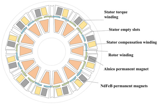
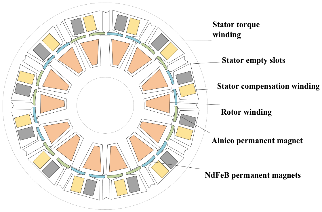
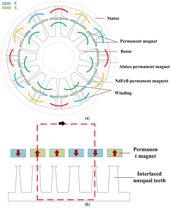
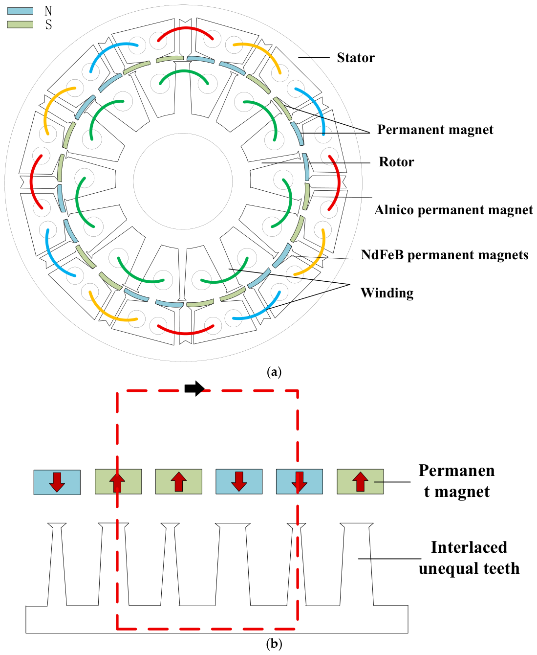
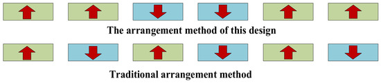
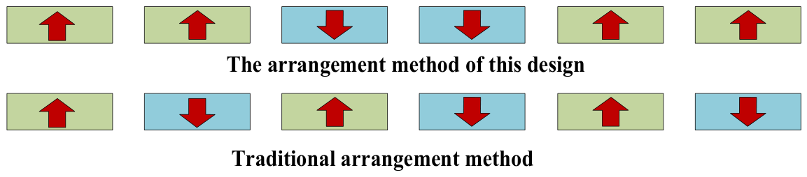
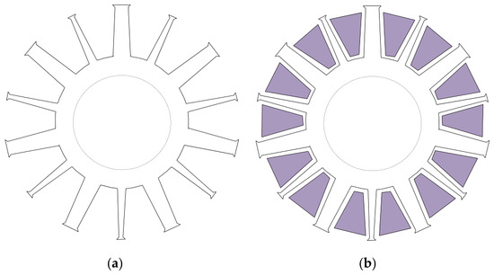
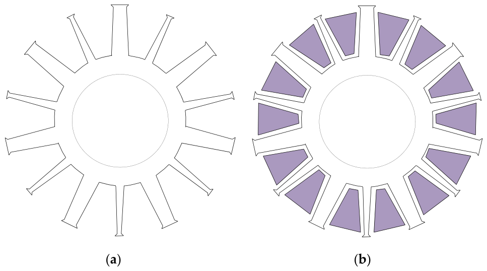
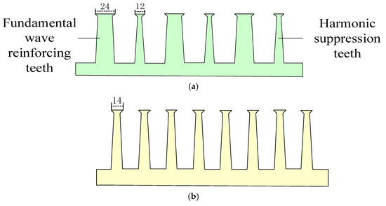
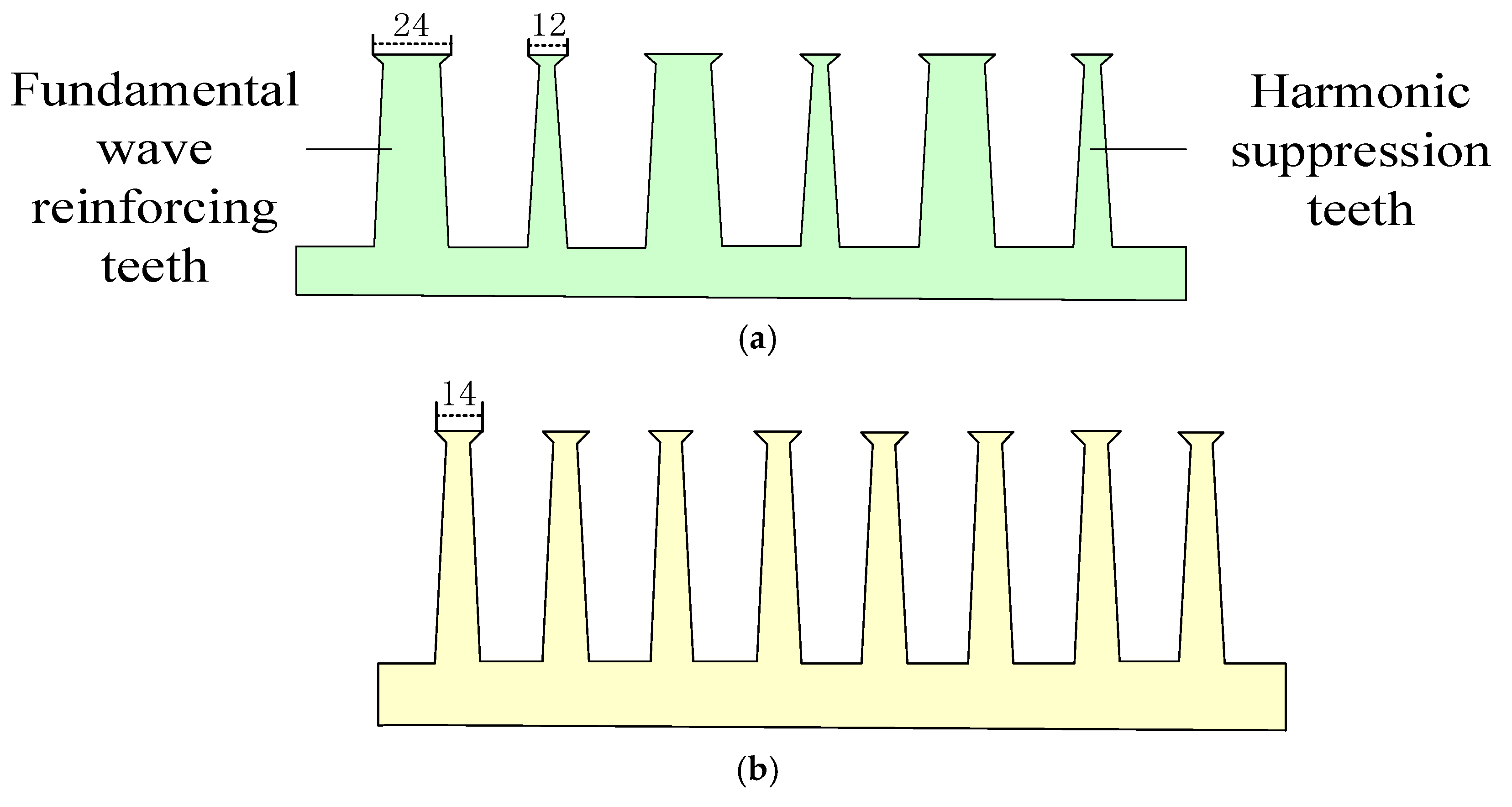
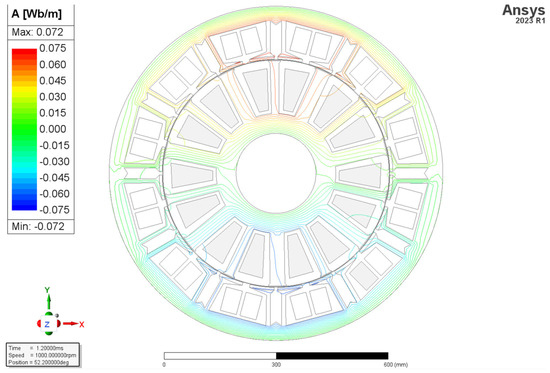
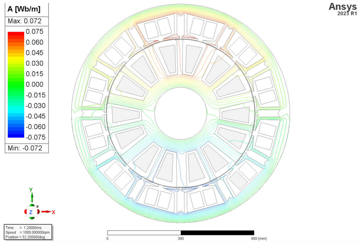
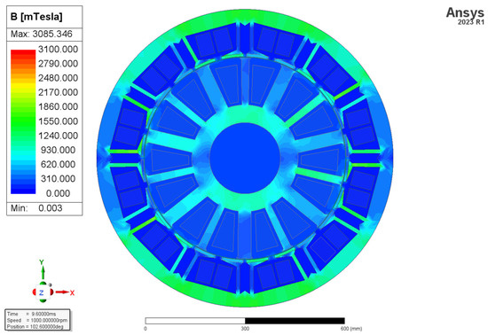
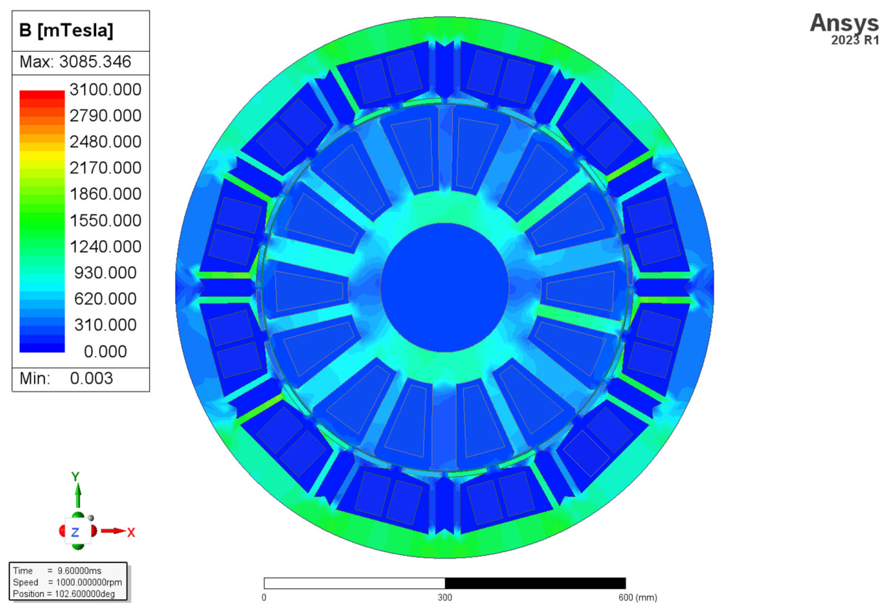
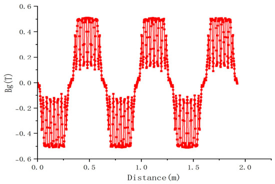
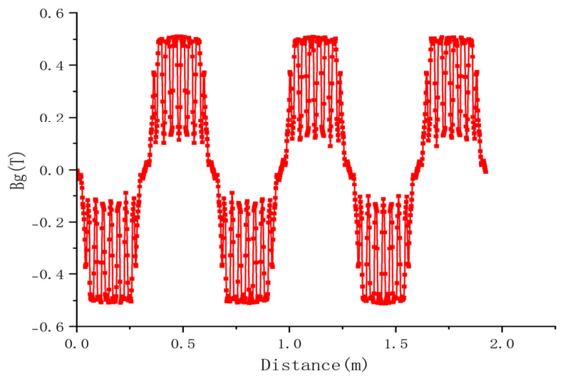
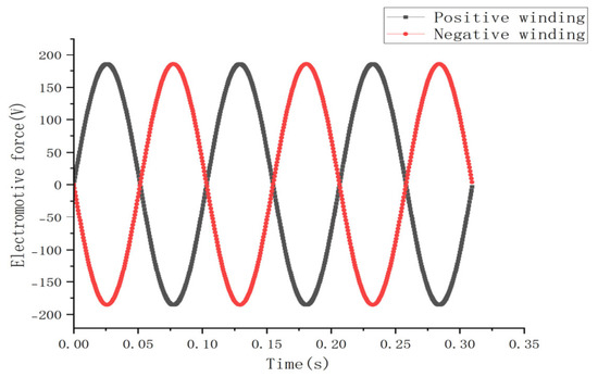
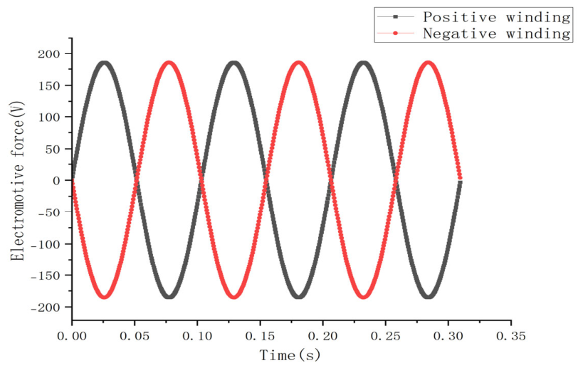
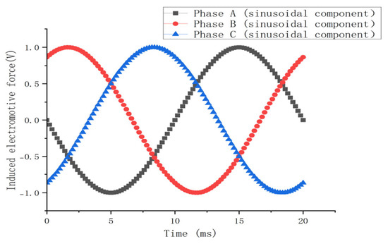
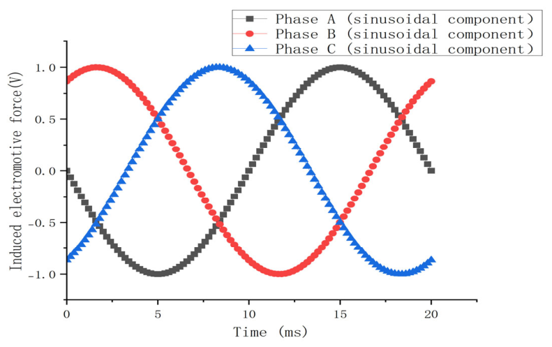
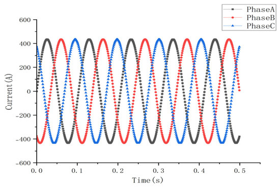
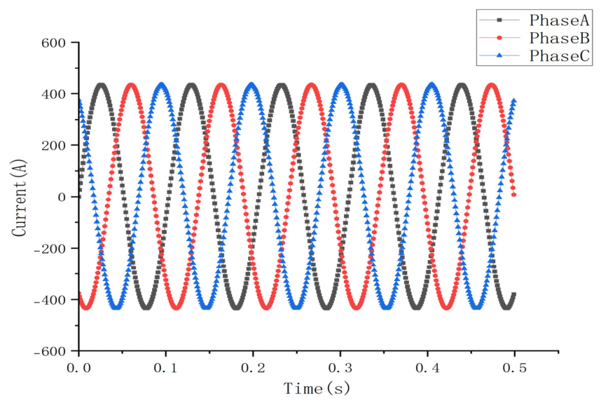
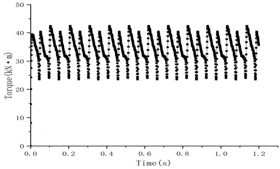
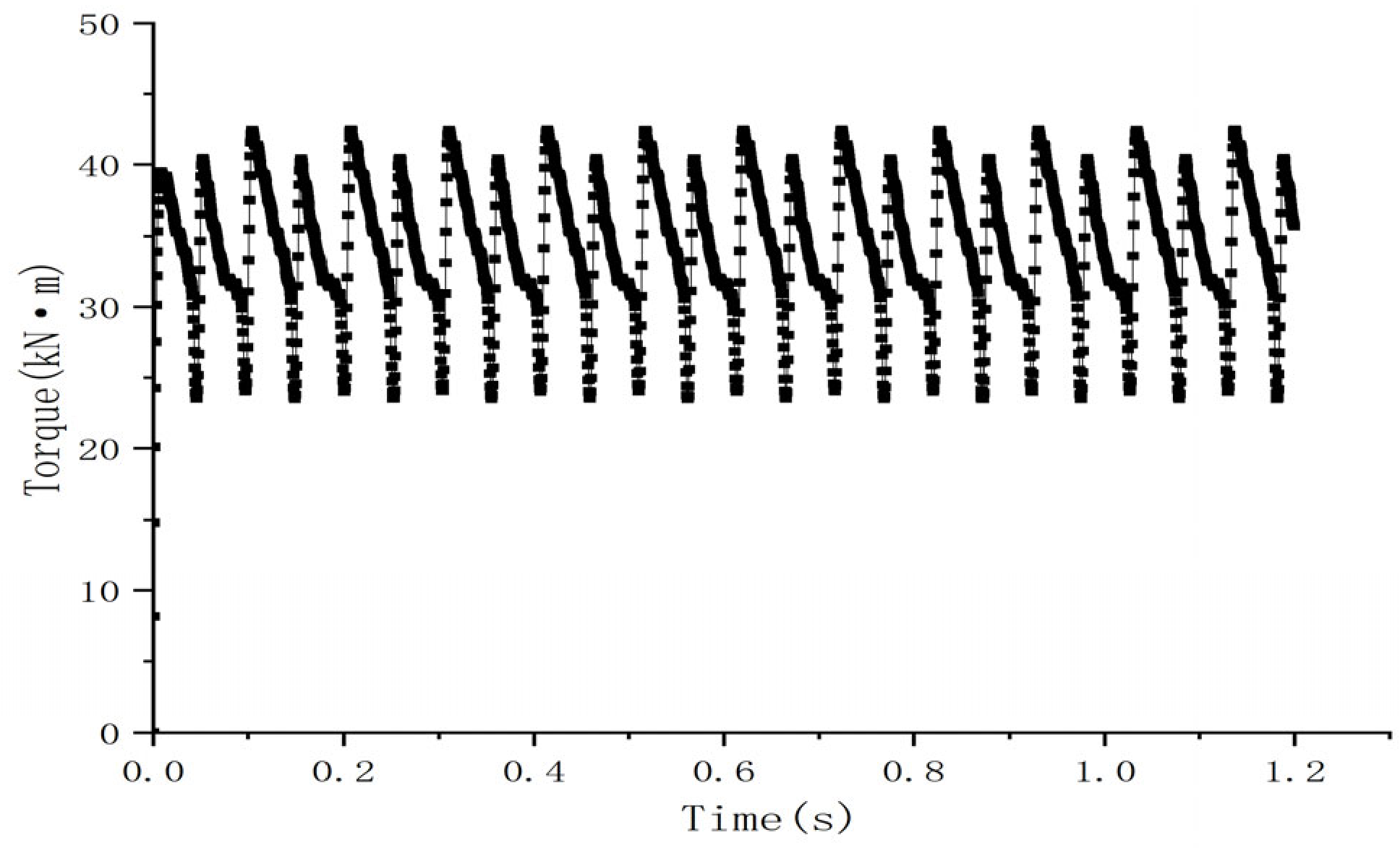
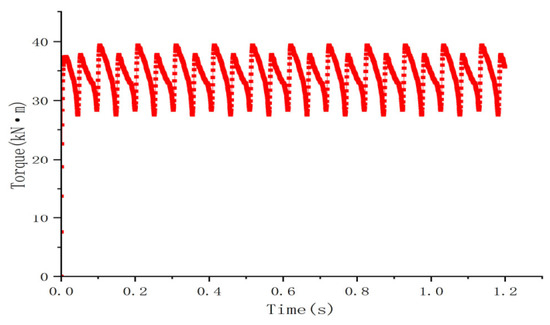
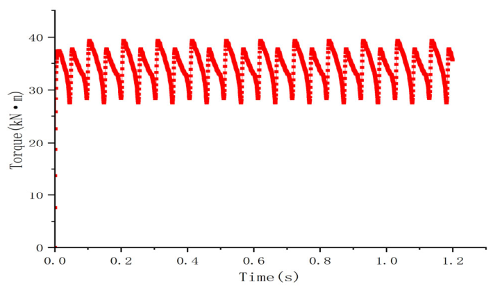

Disclaimer/Publisher’s Note: The statements, opinions and data contained in all publications are solely those of the individual author(s) and contributor(s) and not of MDPI and/or the editor(s). MDPI and/or the editor(s) disclaim responsibility for any injury to people or property resulting from any ideas, methods, instructions or products referred to in the content. |
© 2026 by the authors. Published by MDPI on behalf of the World Electric Vehicle Association. Licensee MDPI, Basel, Switzerland. This article is an open access article distributed under the terms and conditions of the Creative Commons Attribution (CC BY) license.