


Abstract
An integrated Model-Opti-Scale (MOPS) computer system for the modeling, optimization, and scaling-up of plastic extrusion has been built. This enabled simulations of single-screw extrusion with conventional, gravitational feeding of the extruder and single-screw extrusion with metered feeding. This system enables predictions of the behavior of these processes using material, geometry, and operating data and contains numerous original and unique models and algorithmic solutions. The system co-operates with specially developed optimization and scaling procedures based on Genetic Algorithms, allowing process optimization/scaling-up. A unique, holistic approach to modeling flood-fed/starve-fed processes, with a possibility of transfer between these feed methods, is presented. The problem of optimizing the operating/geometry parameters of single-screw extrusion for maximizing process efficiency and minimizing specific energy use has been solved. Optimization has been achieved in a unique way, allowing the coupling of both methods of feeding. It has also been observed that an optimal solution may be obtained upon flood feeding or starve feeding, depending on the assumed weights of the optimization criteria. This optimized process was scaled up to increase process efficiency by enlarging the extruder diameter while keeping the length/diameter ratio constant. Scaling-up has been achieved using criteria comprising single parameters, including specific energy consumption, material temperature, and the plasticization rate, as well as criteria comprising functional parameters, such as temperature distribution and the material plasticization profile.
1. Introduction
Extrusion is, next to injection molding, the most important plastics processing technique. It is also the most common mass-production technique used to produce various types of profiles, as well as pipes, films, etc. It is also applied in compounding processes.
Extrusion can be carried out in single-screw or twin-screw systems, co-rotating or counter-rotating. These can be flood-fed (with gravitational feeding) or starve-fed (with metered feeding), i.e., with material dosing. Dosing is typically used in twin-screw extruders.
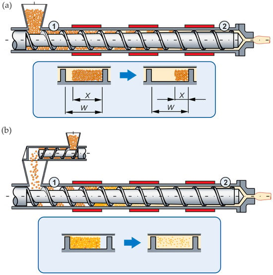
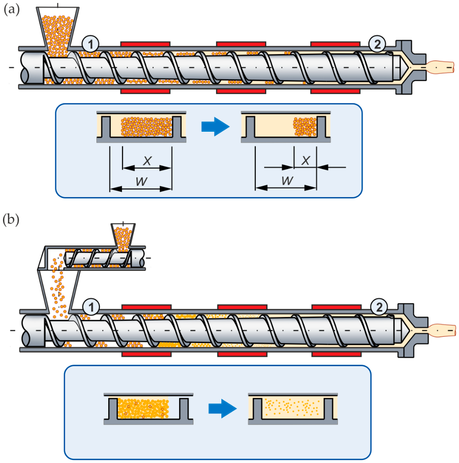
In gravitational feeding, the screw draws in as much plastic as it can handle and is thus fully filled. In dosed feeding, the plastic is fed into the machine via a feeder, and the screw is not fully filled with plastic (Figure 1).
Figure 1.
Plasticization in single-screw extrusion: (a) flood feeding, (b) starve feeding, (1) solid transport region, and (2) melt transport region. X—solid bed width; W—channel width.
The first extruders were ram machines. Screw machines appeared in the 1860s. The literature on extrusion is very extensive, and many books and chapters have been written on this topic, e.g., [1,2,3,4,5,6,7,8,9,10,11,12,13,14,15,16,17,18,19,20,21,22,23,24,25]. What is interesting is that groundbreaking work in extrusion occurred in the last century, e.g., [2,3,5,7,9,10], and at the beginning of this century, e.g., [14,15,18,21,22,23].
The design of plastics processing is currently supported by process simulations. These enable prediction of the process behavior by using material, geometry, and operating data. For example, extrusion can be described by its flow rate, temperature, pressure distribution, energy use, mixing efficiency, etc. This means that output process data can be predicted when using input data.
The first description of material transport in screw machines (screw pump), both isothermal and Newtonian, was given by Finlayson and Rowell [26] for viscous oils. This was reconsidered by Carley’s group [27], who developed the first model of plastics flow in an extruder. Later, many researchers improved these basic models by developing 3D, non-Newtonian, and non-isothermal ones in an actual screw geometry, considering mechanical/thermal coupling, e.g., [28,29,30].
Solid transport in an extruder was considered first by Mol and Darnell [31]. The solid pellets were assumed to be compacted into a solid bed, which moves due to friction on the barrel (cylinder) and screw. Later, other researchers extended this approach, e.g., [32,33]; however, the basic analysis remained unchanged. Some investigations, e.g., [34], showed that basic assumptions are no longer valid since relative movement of pellets takes place in the extruder. Thus, the discrete element method (DEM) was taken into account. This research concept is beneficial in that each pellet and its interaction with others can be modeled individually. However, higher computing time is an important drawback.
Basic 3D DEM simulations of compacting pellets in single-screw machines were carried out by Thompson and Moysey [35,36]. Research by Schöppner et al. [37] has been performed, considering axial pressure development in the feed region of single-screw machines. The DEM concept has also been applied to model solids transport in twin-screw machines [38]. However, so far, this method has not been applied to extrusion global modeling since it is very time-consuming. First, tests of material plasticization in an extruder were performed by Maddock and Street [39,40]. An analysis of a material removed from a screw allowed recognition of the plasticization process. It was observed that a melt film appears on the solid surface, which is scraped off and accumulates at the active screw flight (Figure 1a). Plasticization progresses; the solid decreases by heat conduction from the cylinder and viscous dissipation in the molten plastic.
Tadmor et al. [41,42] developed the first plasticization model for single-screw extrusion and formulated the first global model of the process, called EXTRUD [43]. Others extended the work of Tadmor, e.g., [44,45,46], but the basic analysis remained unchanged. Next, several computer models of single-screw extrusion have been built, e.g., NEXTRUCAD by Vlachopoulos and Agur [47], PASS by Rakos and Sebastian [48], REX by Potente et al. [49], and SSEM by Wilczyński [50], who extended the first basic models of neat polymer extrusion with conventional screws to advanced models of extrusion with non-conventional screws [51,52], and extrusion of polymer blends [53] as well as polymer composites [54,55,56]. Valuable models were also developed by Nomura et al. [57], Karnis and Zavadsky [58], and Lafleur et al. [59].
Twin-screw processing is much less researched than single-screw processing. Co-rotating twin-screw processing was first studied by White’s group. Based on melt and plasticization studies [60,61,62,63], they built the first model, called AKRO-CO-TWIN [62]. Independent studies were performed by the Potente group [64,65], who developed the SIGMA program [66], and by the Vergnes group, who developed the LUDOVIC program [67]. A counter-rotating twin-screw process was also first studied by White’s group. Based on the melt and plasticization studies [68,69,70,71], they built the first model, called AKRO-COUNTER-TWIN [72]. This was continued by Wilczyński’s group, who developed the TSEM (Twin-Screw Extrusion Model) program [73,74,75,76,77].
Although the flood-fed process was extensively investigated, little information was presented on the starve-fed process [78]. Wilczyński et al. [79], based on experiments, first proposed the plasticization model for this process [80]. According to this model, two phases of plasticization were distinguished: plasticization by conduction in the partially filled region of the screw, and plasticization by energy dissipation in the fully filled region, where the pellets are dispersed in molten material (Figure 1b). Based on this, the first and only currently available model of the process was built [81,82]. This was later extended to non-conventional screws [52,83] and extrusion of polymer blends [84,85], as well as polymer composites [86,87,88,89].
It is worth noting that the starve-fed process has some benefits over the flood-fed process, e.g., [22,78,90,91,92,93]. Generally, starvation improves plasticization and mixing actions, reduces power/energy consumption, and results in a small reduction in extrusion output.
One issue with plastics extrusion modeling was discussed in fundamental monographs, e.g., by White and Potente [14], Rauwendaal [22], and the Agassant group. [23], and in review articles, e.g., by Ariffin et al. [94], Teixeira et al. [95], Malik et al. [96], and Wilczyński et al. [97,98].
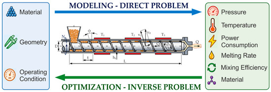
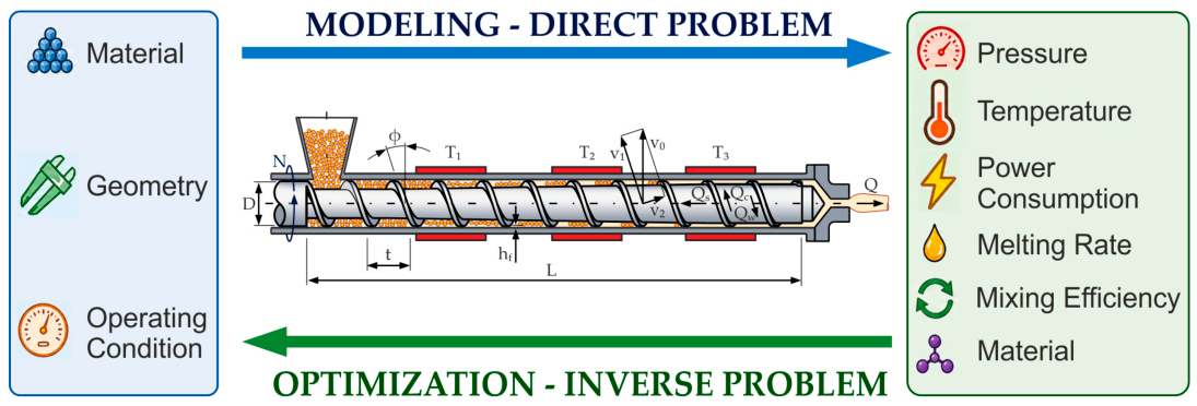
Computer modeling is useful in process design; however, it does not allow solving an inverse problem of defining the process input variables to obtain optimal output variables. Thus, this does not enable optimization of the process in terms of specific optimization criteria. Modeling (simulations) is a direct issue, while optimization is an inverse issue (Figure 2).
Figure 2.
Direct (modeling/simulations) and inverse issues (optimization) regarding plastics extrusion: L, D, t, φ, h—geometry data; N—screw speed; Q—throughput; T—temperature data; V—screw circumferential velocity.
There are two concepts for solving the optimization issue: experiments or simulations. Experiments come first; the optimum was simply the best of what had been attempted. However, it was time-consuming, expensive, and there was no guarantee of finding a global optimum.
Underwood [99] and Verbraak and Meijer [100] were the first to use DOEs (Design of Experiments) to optimize the extrusion process. The optima were found by searching the extremes on the response surface relating to the input/output variables. The main drawback of this was the number of experiments needed.
Therefore, using simulations seemed to be more effective. First, optimization via simulation was performed by Tadmor and Klein [5], Maddock and Smith [101], and Helmy and Parnaby [102]. Potente et al. developed a more sophisticated strategy for screw optimization by means of DOEs (Design of Experiments), using the extrusion model REX [49,103]. Lafleur and Thibodeau used their own extrusion model [59,104]. Statistical procedures were also applied by the authors using SSEM (Single-Screw Extrusion Model) software [51]. The main disadvantages of using statistics were the number of simulations needed and the danger of finding local optima rather than a global one.
Artificial Intelligence (AI), e.g., Genetic Algorithms (GA), Neural Networks (NN), and Fuzzy Systems (FS), can also be used to optimize the extrusion process. Basic investigations with Genetic Algorithms were conducted by Covas and Gaspar-Cunha, who were the first to elaborate the optimization algorithms for the single-screw [105,106] and co-rotating twin-screw processes [107,108]. The authors proposed optimization by using Neural Networks and Genetic Algorithms for the single-screw process, both flood-fed and starve-fed [109], as well as for the counter-rotating twin-screw process [110]. However, an issue of optimizing the extrusion process has been recently summarized by Nastaj and Wilczyński [111].
Genetic Algorithms, compared to other optimization techniques, differ in the following manner:
- -
- Optimization variables are used in coded form;
- -
- Seeking a solution starts from some populations; therefore, becoming stuck in a local extremum is less likely;
- -
- A new search area is based on previous experiences;
- -
- Selections are probabilistic;
- -
- The objective function is needed, not its derivatives.
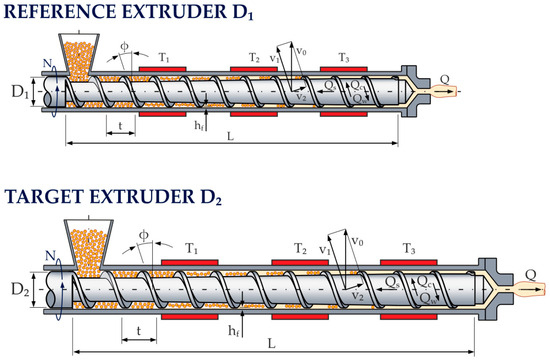
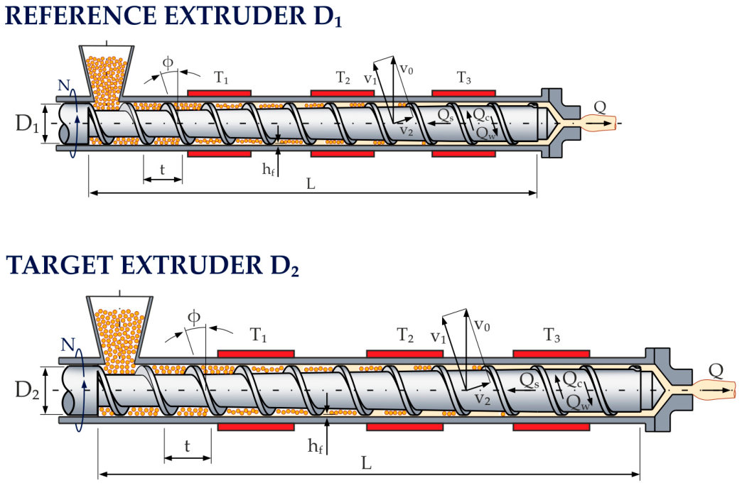
Another concept of designing in plastics extrusion is what is known as scaling-up, i.e., increasing the scale of the process by using specific criteria, such as increasing process efficiency while keeping the scaling variables as close (similar) to the reference process as possible. Thus, this consists of minimizing the differences between the variables of the reference/target processes. This concept results from the theory of similarity in fluid mechanics. The scaling-up concept for plastics extrusion is shown in Figure 3.
Figure 3.
Scaling-up in plastics extrusion: D1—reference screw; D2—target screw.
McKelvey and Carley [112] were the first to carry out the scaling of extrusion. They developed scaling-up rules for screws in which the channel depth/width were enlarged in proportion to the screw-to-diameter ratio at a constant screw speed. Other scaling-up concepts were later developed [113,114,115,116,117,118,119,120,121], among which Pearson [115] was the first to perform a full analysis of the process, considering solid conveying, material plasticization, and melt conveying. He achieved acceptable scaling-up when the numbers of Brinkman, Graetz, and Nahme were kept constant.
Covas and Cunha [122] concluded that more effective scaling-up concepts are necessary and should be based on the model of the process that enables the simultaneous application of several scaling-up criteria, as well as the selection of single parameters (e.g., plasticization rate) or functions (e.g., plasticization progress along the screw) as scaling-up criteria.
They proposed considering extrusion scaling as a multi-objective optimization issue, where the goal is to define the geometry/operation data of the target extruder in such a way that the performance data of both extruders are as close (similar) as possible.
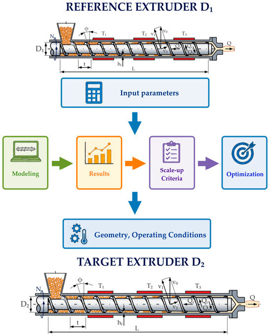
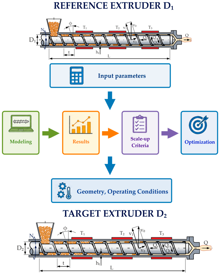
The goal of scaling is to minimize the differences between selected process variables of the target/reference extruders. This concept involves process modeling/simulations, defining the scaling criteria, and multi-objective optimization. The scaling criteria are computed for the target process and compared with the criteria of the reference one, and each computation is evaluated. Searching for a good solution is repeated until a satisfactory minimization of the differences is obtained. This concept is presented in Figure 4.
Figure 4.
The optimization concept of the scaling-up of plastics extrusion process: D1—reference screw; D2—target screw.
Using this multi-objective optimization concept [105,106,107,108], Covas and Cunha [122] were the first to perform comprehensive scaling-up of the conventional flood-fed single-screw process in terms of screw geometry and operating data. This concept was later applied to various scaling-up issues of the single-screw and co-rotating twin-screw processes [123,124,125,126,127]. Recently, the authors developed scaling-up algorithms for the starve-fed single-screw [128] and counter-rotating twin-screw processes [129]. The state-of-the-art in this area has been recently presented in the review article [111].
It can be concluded that using process simulations seems to be a fundamental and most effective concept for both optimizing and scaling up plastics extrusion.
As evidenced by the presented literature review, modeling, optimization, and scaling are subjects of research and scientific debate. However, a system that would enable an integrated design of the extrusion process by using these design techniques is lacking. There is also a lack of a system that would enable smooth transitions between different extrusion techniques, such as extrusion with material dosing and extrusion without material dosing. This paper presents such a system that, based on a holistic approach to design, addresses these issues. In this paper, using this system, the design of single-screw extrusion based on process modeling, optimization, and scaling up has been performed.
2. Model-Opti-Scale System
The Model-Opti-Scale (MOPS) system is composed of three closely related and co-operating subsystems: GSEM (Global Screw Extrusion Model) for simulation of the single- screw process, GASEO (Genetic Algorithms Screw Extrusion Optimization) for process optimization, and GASES (Genetic Algorithms Screw Extrusion Scaling) for process scaling. The system enables the design of the extrusion process based on process modeling, optimization, and scaling, in dosed and non-dosed feeding conditions (starve-fed/flood-fed), with the possibility of transfer between these feed methods.
2.1. Process Modeling
Process modeling was carried out by the GSEM (Global Screw Extrusion Model) program, which has been designed to simulate the single-screw process, both flood-fed and starve-fed. This enables simulations of the process with the use of conventional/non-conventional screws and dies of various geometries. The program simulates the extruder/die system, enabling prediction of the flow rate (when flood-fed), screw filling (when metered-fed), temperature and pressure profiles over the extruder/die length, plasticization of material, and energy use, etc. The simulation data include material characteristics, screw/die geometry, and operating conditions.
The global model of the extrusion process consists of elementary screw models and a die model. The polymer mass flow rate is constant in screw/die increments, and the process parameters may be assumed locally constant in these increments. This modeling approach is called lumped parameter modeling, which is accurate enough for engineering practice and applications. The parameters of the extrusion process, e.g., flow rate, temperature, power, pressure, screw filling, at the onset of the current screw increment are equal to the parameters at the exit of the former increment, i.e.,
where fi_in (z) is the input data (temperature, pressure, or solid material content) at the onset of the increment; fi−1_out (z) is the output data at the exit of the (i − 1) increment; z is the coordinate along the screw/die axis; and Δz is the screw/die increment.
fi−1_out (z) = fi_in (z)
fi−1_out (z + Δz) = fi_in (z + Δz)
Summarizing, the model consists of elementary models, depending on the material being processed (pure polymers, polymer blends, WPC):
- -
- Model of the solid conveying section;
- -
- Model of the melting section;
- -
- Model of the screw melt conveying section using the three-dimensional, non-Newtonian flow characteristics;
- -
- Model of the die-flow section using the three-dimensional, non-Newtonian flow characteristics.
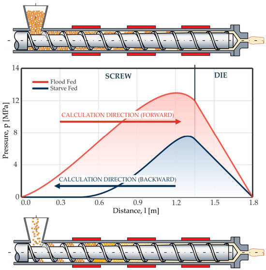
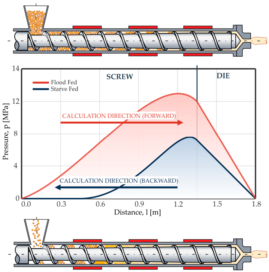
Extrusion modeling requires a computation algorithm that is appropriate to the type of extruder feeding. In the GSEM program, when flood-feeding, the forward algorithm is used. The material flow rate is not known here, and the results from the extruder/die operation have to be calculated in multiple iterative computations. When metered-feeding, the backward algorithm is used. The flow rate is known here, and it is equal to the flow rate of the material supplied by the dosing instrument (Figure 5).
Figure 5.
Forward algorithm for flood-fed process vs. backward algorithm for metered-fed process.
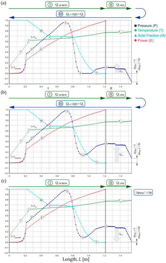
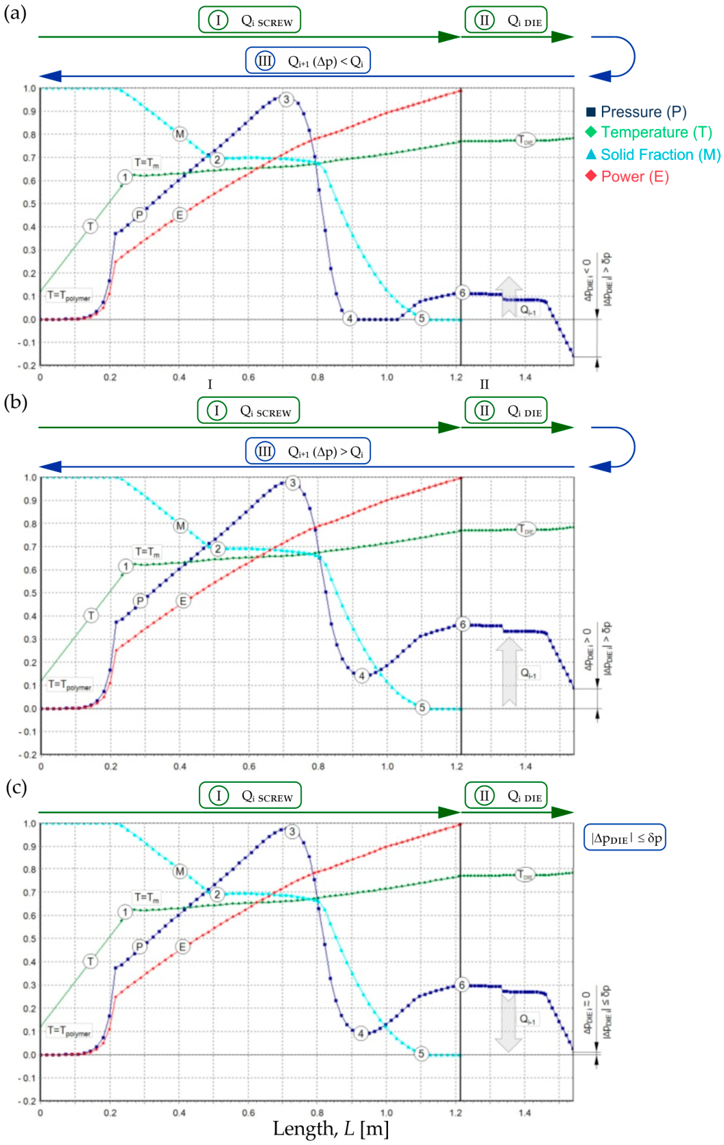
The course of simulation of the flood-fed extrusion is presented in Figure 6. The modeling progresses from the hopper to the die (forward algorithm), and the process operating point is sought, which determines the process output and die pressure. Calculations start with a presumed flow rate, and then solid transport, material plasticization, and melt transport are simulated. The pressure at the die outlet is compared to atmospheric pressure, and the calculation is correct when both pressures are equal. Otherwise, the flow rate is varied, and the calculation is repeated until convergence is obtained.
Figure 6.
Course of simulation of the flood-fed process: (a) Δpdie < 0; (b) Δpdie > 0; (c) ׀Δpdie׀ < δp. 1—origin of material plasticization; 2—origin of compression (transition) region; 3—pressure maximum; 4—finished pressure drop; 5—finished material plasticization; 6—pressure at screw outlet (die inlet); Q—flow rate; Qi+1—next flow rate value; P—pressure; ΔpDIE—pressure at die outlet; δp—pressure calculation accuracy; T—temperature; Tm—melting point; TDIE—melt temperature (die region); M—solid fraction (plasticization), E—power.
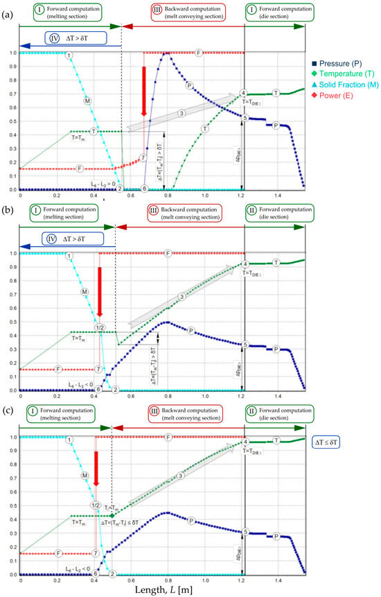
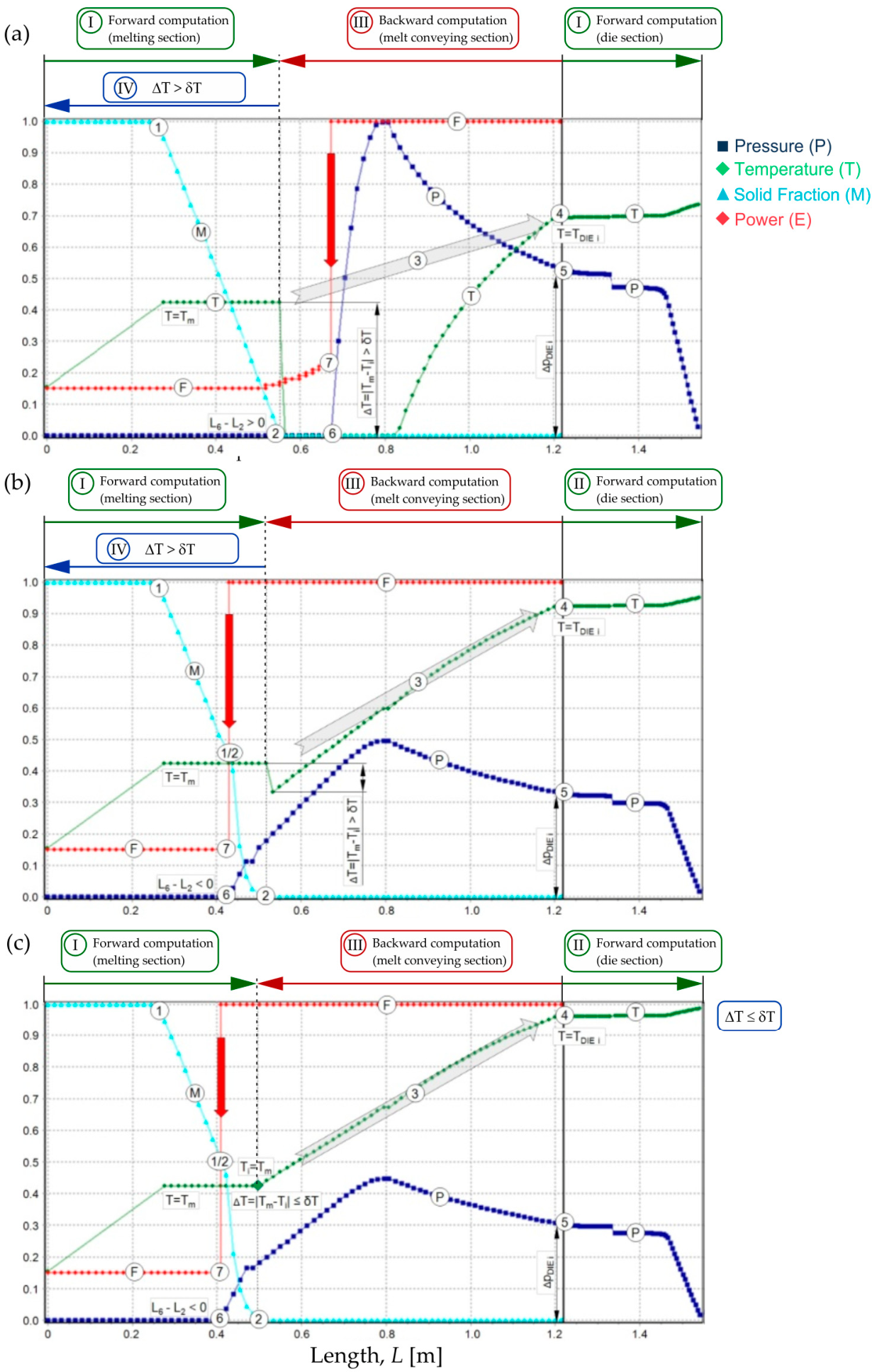
The course of simulation of the starve-fed process is presented in Figure 7. In this case, the backward algorithm of computation is used. The flow rate is equal to the feeding rate, and the die pressure is calculated first for a presumed melt temperature. The pressure gradient over the screw length is calculated (as well as the temperature) with the use of screw-pumping characteristics. When the pressure diminishes to zero, the starvation origins and the screw filling (filling factor) are calculated. The temperature at the plasticization end is compared to the melting point, and the calculation is correct when both temperatures are equal. Otherwise, the melt temperature is varied, and calculations are repeated until convergence is obtained.
Figure 7.
Course of simulation of the starve-fed extrusion: (a) 1-phase plasticization mechanism, lack of calculation convergence; (b) 2-phase plasticization mechanism, lack of calculation convergence; (c) calculation convergence. I—forward calculations (melting region); II—forward calculations (die region); III—backward calculations (melt conveying region); IV—next iteration; M—solid fraction (plasticization); F—filling (fill factor); T—temperature; P—pressure; 1—origin of material plasticization; 2—finished material plasticization; 3—transfer of calculations to the die; 4—origin of melt temperature calculations; 5—origin of die pressure calculations; 6—zero pressure location; 7—origin of filling calculations (partially filled region starts); ΔPDIEi—die pressure; TDIEi—presumed melt temperature; Tm—melting point; i—number of iterations; ΔT = |Tm − Ti|, convergency testing; δT—temperature computation accuracy.
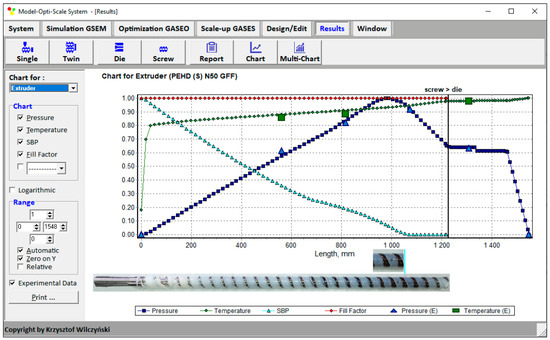
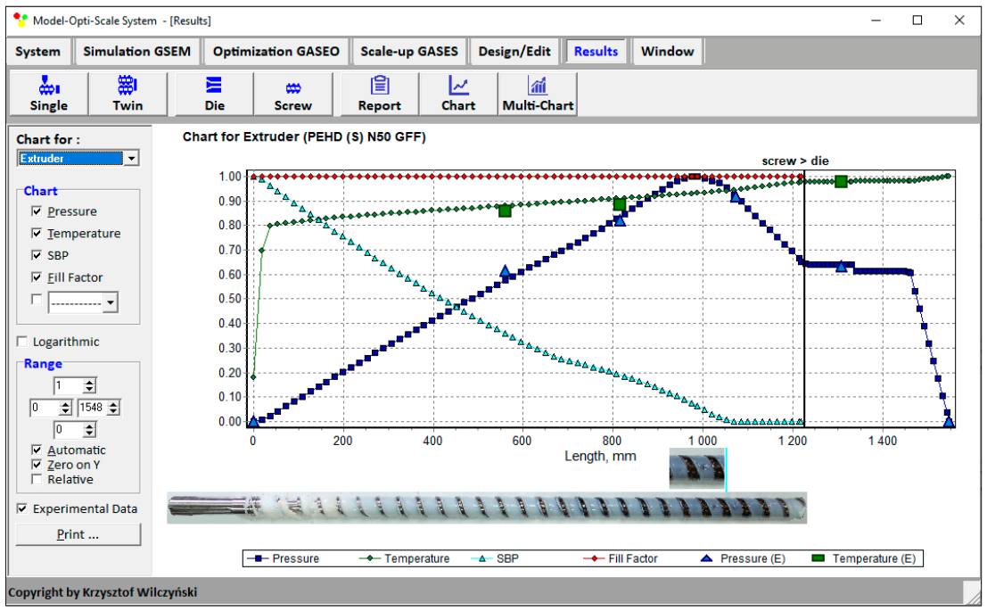
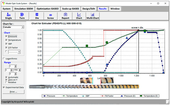
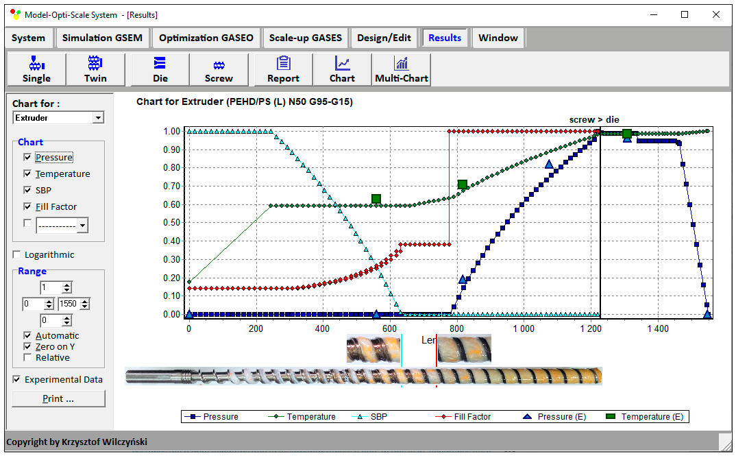
The simulation examples are shown in Figure 8 and Figure 9. The process characteristics include pressure/temperature distributions, as well as material plasticization progress (solid bed profile, SBP). In addition, for starve-fed extrusion (Figure 9), a screw filling profile is presented (when starvation begins, the pressure diminishes to zero). Two phases of plasticization are seen, as well as the partially filled and fully filled regions.
Figure 8.
Extrusion process characteristics: simulations and experimental data for flood-fed extrusion: SBP—solid bed profile (material plasticization); E—experiment.
Figure 9.
Extrusion process characteristics: simulations and experimental data for starve-fed extrusion: SBP—solid bed profile (material plasticization); E—experiment.
These simulations (by the GSEM model) were experimentally validated in the authors’ previous studies, and the simulation–experiment comparisons shown in Figure 8 and Figure 9 provide an illustrative confirmation of its predictive capability. In contrast, the optimization and scale-up results presented in the following sections constitute computational demonstrations of the corresponding MOPS modules.
2.2. Process Optimization
Process optimization was carried out by the GASEO (Genetic Algorithm Screw Extrusion Optimization) program. The source of data for optimization is the simulations carried out by the GSEM (Global Screw Extrusion Model) program.
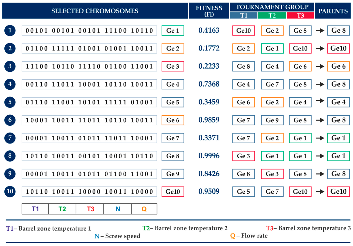
The GASEO optimization program, in co-operation with the GSEM simulation program, enables extrusion process optimization with any number of variables and various optimization criteria, e.g., process output or energy use. The accuracy of searching the response surface is defined by the number of divisions of the variable range, which results from the binary representation of variables. In the GASEO program, the binary chromosome length is adjustable, with a maximum length of 255 bits. This allows the range of each variable to be divided into 2255 values. A tournament selection method is used for parent selection because of its simplicity, robustness, and lower sensitivity to scaling the objective function. In this method, a group of randomly selected genotypes participates in a tournament, and the genotype characterized by the highest objective function value is selected as a parent. The procedure is repeated until the required number of parents is obtained. A scheme of the tournament selection method is presented in Figure 10. For example, in a tournament composed of genotypes Ge2, Ge10, and Ge8 (first line), the Ge8 genotype is selected because it generates the highest objective function value. Similarly, in another tournament consisting of Ge2, Ge1, and Ge10 (second line), the Ge10 genotype becomes the parent genotype due to its superior fitness value. In this way, genotypes with higher objective function values have a greater probability of being selected for reproduction while preserving population diversity.
Figure 10.
Selection of initial population and evaluation of chromosome adaptation.
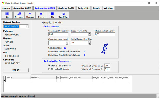
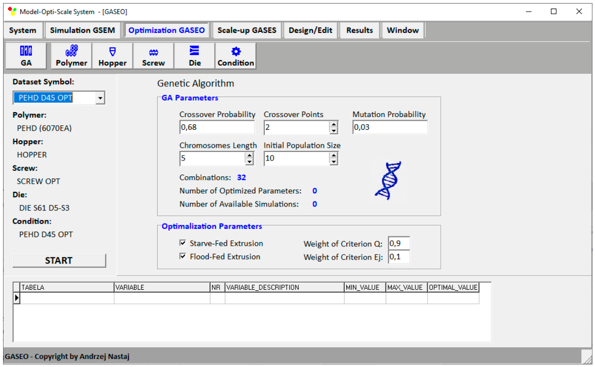
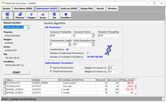
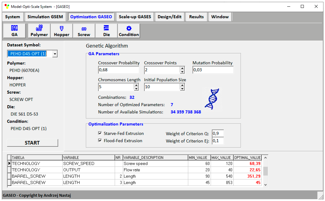
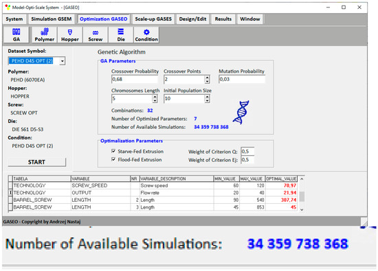
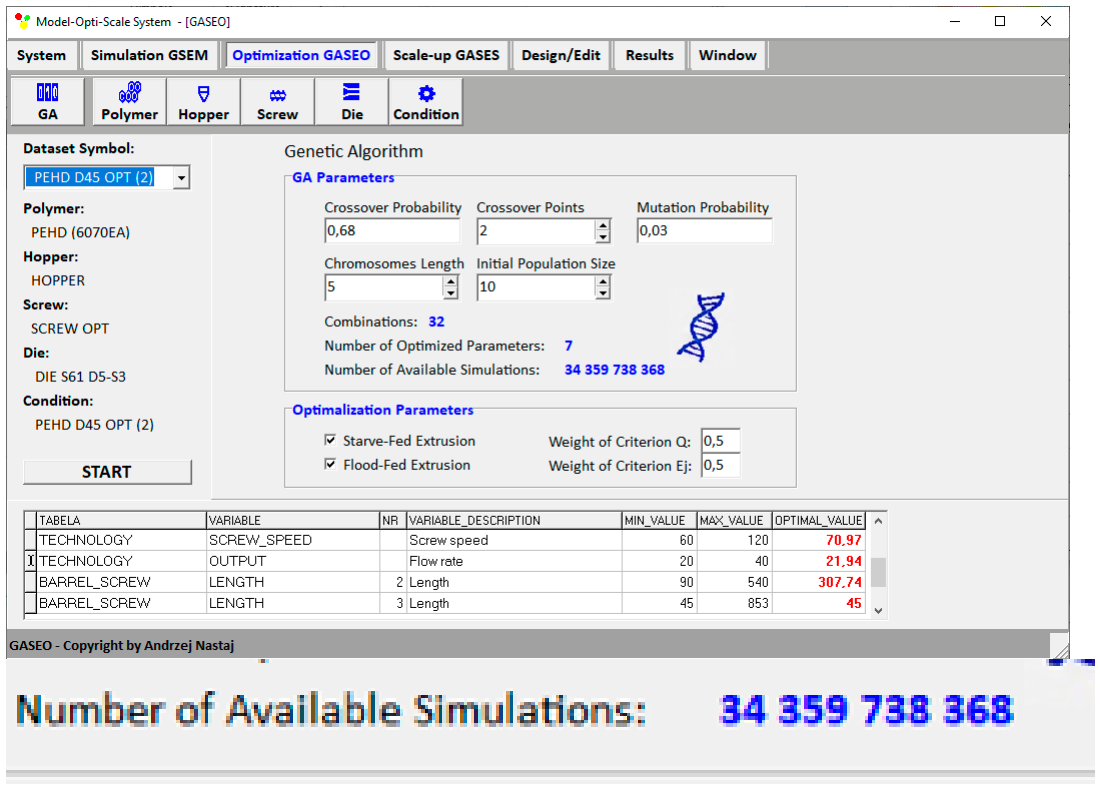
The optimization procedure was defined by Genetic Algorithm variables, including the number of optimized variables, population size, chromosome length, crossover probability, number of crossover points, and mutation probability. Optimization can be carried out selectively for either the flood-fed process or starve-fed process. Moreover, optimization can be performed in a coupled manner, where both feeding modes are simultaneously allowed. This is illustrated in Figure 11.
Figure 11.
Parameters defining the optimization procedure.
Optimization was performed using an initial population of 10 individuals. Each design variable was encoded using a 5-bit binary representation. The crossover and mutation probabilities were set to 0.68 and 0.03, respectively. These parameters were selected as a compromise between computational efficiency and search capability. Since each fitness evaluation requires a complete simulation of the extrusion process, the population size was intentionally kept relatively small to reduce computational time while maintaining sufficient genetic diversity. The adopted crossover and mutation probabilities provided an appropriate balance between exploration of the search space and convergence toward the optimum solution. The optimization procedure was terminated when population stagnation was detected, i.e., when the best objective-function value remained unchanged for 20 consecutive generations. Additionally, a maximum of 100 generations was imposed to prevent excessive computational time. This stopping criterion was preferred to a fixed-generation approach because it allows optimization to continue only while the population evolves toward improved solutions.
One optimization run was performed for each weighting combination. Consequently, the present results demonstrate the operation of the optimization module but do not provide a statistical assessment of solution variability or robustness with respect to the initial population.
2.3. Process Scaling-Up
Process scaling-up was carried out by the GASES (Genetic Algorithm Screw Extrusion Scaling) program. The source of data for scaling-up is simulations carried out by the GSEM (Global Screw Extrusion Model) program.
The GASES scaling-up program, in co-operation with the GSEM simulation program, enables the extrusion process to be scaled up with various numbers of scaling variables and different scale-up criteria specified by single process parameters, e.g., specific energy consumption, solids transport rate, material plasticization rate, or pumping rate, as well as by process parameter profiles, e.g., the plasticization profile or temperature profile.
Summarizing, the scale-up criterion consists of five dimensionless objective function terms: three for scalar quantities and two for process profiles. Each term is expressed as an absolute value of relative deviation and contributes equally to the objective function value. The terms corresponding to the temperature and plasticization profiles are determined as the average absolute values of relative deviation calculated for n discretization points. By dividing these terms by n, the profiles do not exert a disproportionate influence on the objective function value simply due to the larger number of data points. As a result, each profile contributes a single, averaged term to the objective function, ensuring a balanced contribution of both scalar quantities and process profiles.
The variable coding procedure, chromosome representation, and response surface discretization applied in the GASES program are identical to those described previously for the GASEO optimization program (Section 2.2). A tournament selection method is applied during the scaling-up procedure to identify genotypes that provide the best agreement with the adopted scale-up criteria. In this approach, several genotypes are randomly selected from the population and compared with respect to the objective function value representing the scaling quality. The genotype characterized by the most favorable scaling result is transferred to the parent population and used in subsequent genetic operations. The selection procedure is repeated iteratively until the complete parent population is created. In the scaling-up procedure, the objective function usually represents the difference between the process characteristics of the reference extruder and those predicted for the target extruder. Consequently, genotypes producing smaller discrepancies with respect to the assumed scale-up criteria are preferentially selected for further evolution.
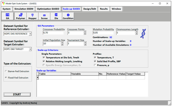
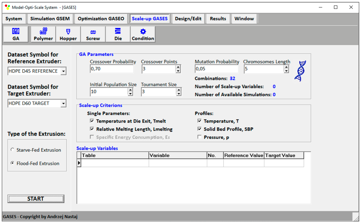
The scaling-up procedure is defined by Genetic Algorithm variables, including the number of scaling variables, population size, chromosome length, crossover probability, number of crossover points, and mutation probability. Scaling-up can be performed for either the flood-fed process or starve-fed process. This is illustrated in Figure 12.
Figure 12.
Parameters defining the scaling-up procedure.
3. Process Design
3.1. Research Program
The problem of optimizing operating/geometry parameters of the single-screw process is presented to maximize process efficiency and minimize specific energy use. Optimization has been achieved in a unique way when both modes of feeding are allowed. This optimized process was then scaled up to increase process efficiency by enlarging the extruder diameter while keeping the length/diameter ratio constant. Scaling-up has been achieved using criteria comprising single parameters, including specific energy consumption, material temperature, and the plasticization rate, as well as criteria comprising functional parameters, such as temperature distribution and the plasticization profile. The simulation study program was developed to demonstrate the capabilities of the integrated Model-Opti-Scale (MOPS) system in modeling, optimization, and scaling the single-screw extrusion process. The system integrates three co-operating computational modules: GSEM (Global Screw Extrusion Model), GASEO (Genetic Algorithms Screw Extrusion Optimization), and GASES (Genetic Algorithms Screw Extrusion Scaling), enabling the comprehensive computer-aided design of plastics extrusion.
Investigations were performed for the single-screw extrusion of high-density polyethylene (HDPE). A conventional, three-zone screw (Figure 13) of diameter D = 45 mm, a length/diameter ratio of L/D = 27, and a compression ratio of CR = 8/3 was used, and a cylindrical rod die of diameter D = 5 mm was applied. The aim of the study was to demonstrate the capabilities of the software in predicting the behavior of the extrusion process under various processing conditions and different material feeding modes.
Figure 13.
Geometry of a conventional screw.
The study was performed for both conventional gravity feeding (flood-fed extrusion) and metered feeding (starve-fed extrusion), which allows partial filling of the screw channel. The software enabled simulations over a wide range of processing parameters, including the screw speed ν = 20–80 rpm, variable lengths of the metering and compression (transition) regions of the screw, and different thermal processing conditions. This made it possible to analyze the influence of geometrical and operating parameters on the plasticization and material transport processes.
Within the modeling framework, the GSEM program enabled the determination of the main process characteristics, such as the pressure and temperature distributions, material plasticization profile, degree of screw filling, process throughput, and energy consumption. A particular feature of the program was its ability to automatically switch between flood-fed and starve-fed operating conditions while keeping the appropriate computational schemes.
Based on the simulation results, optimization of the extrusion process was performed using the GASEO program based on Genetic Algorithms. The study aimed to demonstrate the capabilities of the program in multi-objective optimization of the process while simultaneously considering technological and geometrical parameters. The optimization criteria were maximum process throughput, Gmax, and minimum specific energy consumption, εsmin. The optimized variables included the screw speed as well as the lengths of the metering and compression (transition) regions of the screw. The optimization studies made it possible to evaluate the effectiveness of the GASEO program in searching for optimal process parameters by using Genetic Algorithms and analyzing the influence of input parameters on the process behavior and objective function values.
In the final stage of the study, the GASES program was used to perform extrusion process scaling. The scaling investigations were intended to demonstrate the capabilities of the system in transferring process conditions from a reference extruder to a target extruder while keeping the similarity of process characteristics. The analysis considered criteria related to the material plasticization profile, temperature profile, specific energy consumption, and material flow characteristics.
Scaling procedures were carried out using multi-objective optimization methods, minimizing differences between the process characteristics obtained for the reference and target extruders. The program enabled scaling analysis for both flood-fed and starve-fed extrusion processes, allowing for evaluation of the influence of the feeding mode on keeping process similarity during changes in the scale of the extrusion process.
3.2. Optimization
Optimization was performed for single-screw extrusion of high-density polyethylene (HDPE) using a conventional screw (Figure 13), as in Section 3.1.
Flood-fed and starve-fed processes were investigated. Rigidex 6070EA (produced by BP Chemicals) was used, with a density ρS = 950 kg/m3 (solid), ρM = 720 kg/m3 (melt), and a Melt Flow Rate (MFR) = 7.6 g/10min (190 °C, 2.16 kg).
The polymer viscosity has been described by the Klein model:
where η represents the viscosity, represents the shear rate, Θ represents the temperature, and c0, c1, c11, c12, c2, c22 represent the model parameters (c0 = 10.92, c1 = −0.22, c11 = −0.037, c12 = 0.001, c2 = −0.023, c22 = 0.000021).
Optimization has been performed for both flood-fed and starve-fed processes to maximize process throughput and minimize specific energy consumption . The studies were conducted in two variants, with different weighting factors assigned to process throughput and specific energy consumption . In the first variant, and were assumed, whereas in the second variant, and . These weighting combinations and were selected to represent two illustrative technological priorities. The first case corresponds to a productivity-oriented strategy, in which throughput is assigned the dominant weight, whereas the second one represents a balanced compromise between throughput and specific energy consumption.
The optimized parameters included screw speed ν, cylinder temperatures Θ, and lengths L of the metering and compression (transition) regions, as shown in Table 1.
Table 1.
Research program.
The screw speed range of 20–80 rpm refers to the general simulation examples, whereas the range of 40–120 rpm listed in Table 1 defines the admissible search range used in the optimization calculations. The throughput range of 20–40 kg/h applies to starve-fed operations, for which the material feeding rate is an imposed operating variable. Under flood-fed conditions, throughput is not independently prescribed but is calculated by the extrusion model as a process output.
The global objective function was defined as:
where the output variables (optimization criteria) have been normalized as:
where ϕi represents the global objective function, Gi_norm represents the flow rate, ωG represents the weighting factor of flow rate, εs i_norm represents the specific energy use, ωεs represents the weighting factor of specific energy use, i is the number of the next value from the variable set.
The results of optimizing for flood-fed/starve-fed extrusion are presented in Table 2.
Table 2.
Maxima of global functions at selected weighting factors of optimizing criteria.
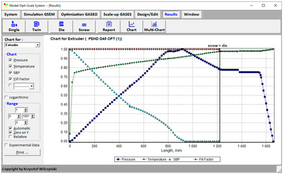
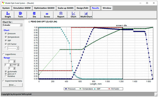
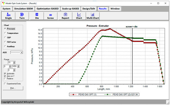
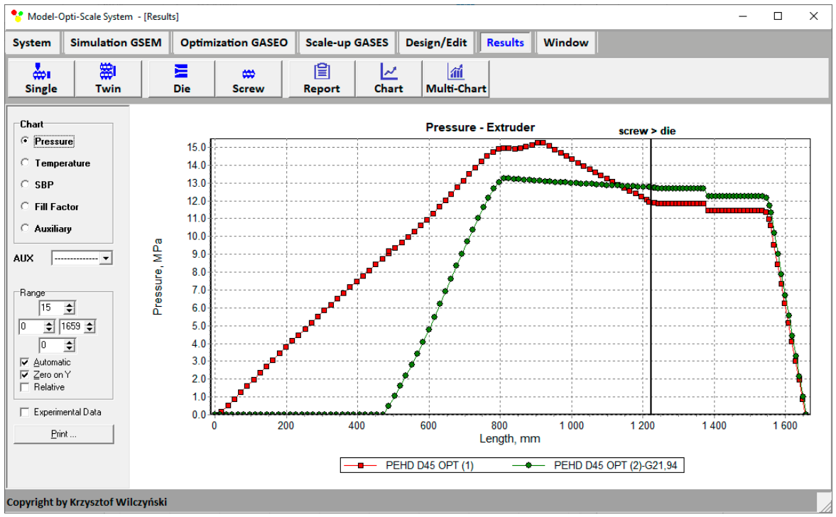
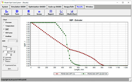
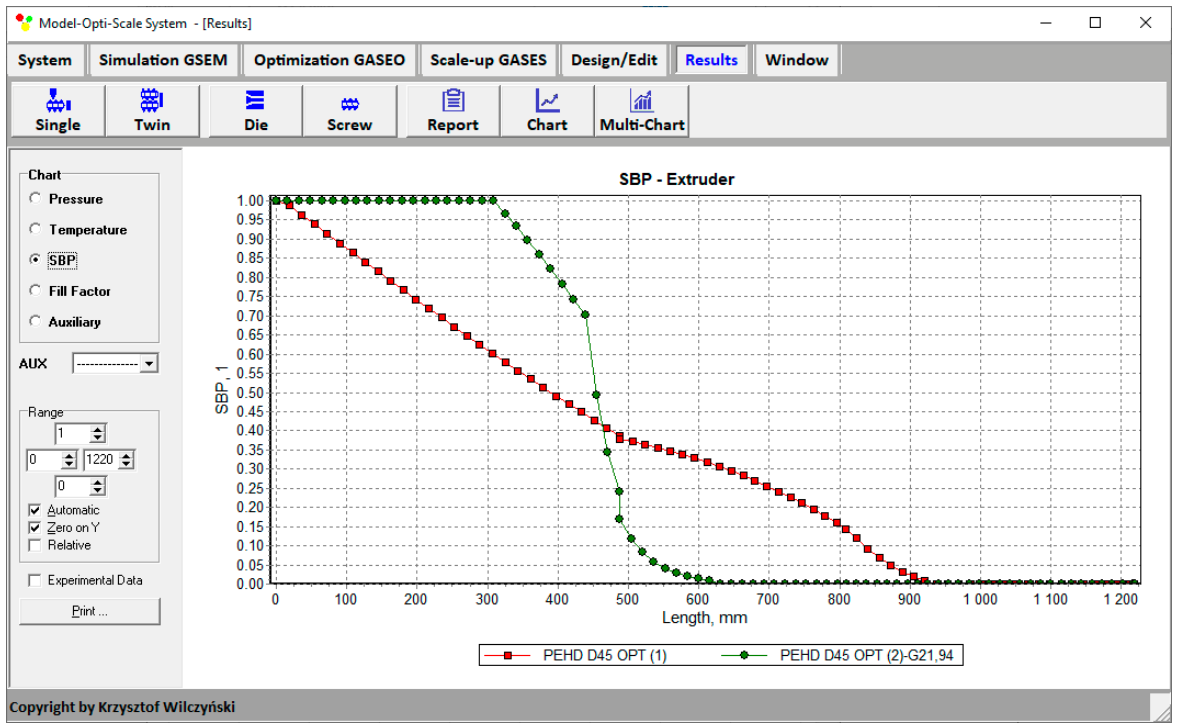
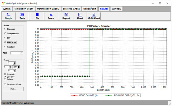
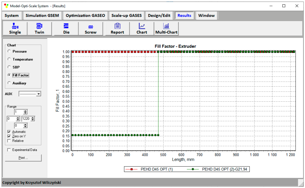
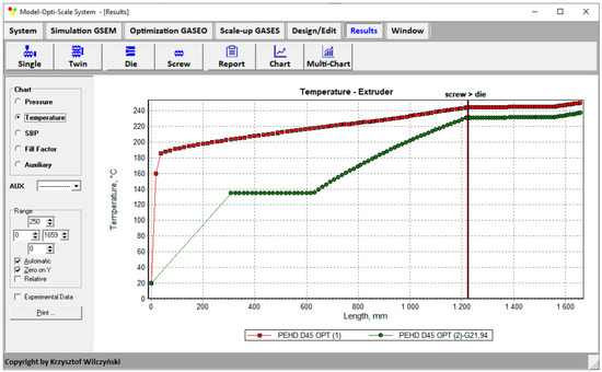
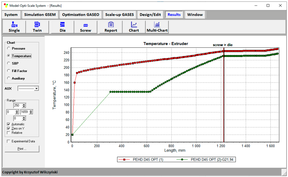
The results of the simulations at optimal parameters for various weighting factors of optimization criteria are depicted in Figure 14, Figure 15, Figure 16, Figure 17, Figure 18, Figure 19, Figure 20 and Figure 21.
Figure 14.
Extrusion characteristics: flood-fed process at weighting factors of optimization criteria ωG = 0.9 and ωεs = 0.1.
Figure 15.
Extrusion characteristics: starve-fed process at weighting factors of optimization criteria ωG = 0.5 and ωεs = 0.5.
Figure 16.
Pressure distributions at optimal parameters for various weighting factors of optimization criteria, ωG and ωεs (Table 2, results 1, 2). Red line—flood feeding; green line—starve feeding.
Figure 17.
Solid bed profiles (SBP) at optimal parameters for various weighting factors of optimization criteria, ωG and ωεs (Table 2, results 1, 2). Red line—flood feeding; green line—starve feeding.
Figure 18.
Filling factor distributions at optimal parameters for various weighting factors of optimization criteria, ωG and ωεs (Table 2, results 1, 2). Red line—flood feeding; green line—starve feeding.
Figure 19.
Temperature distributions at optimal parameters for various weighting factors of optimization criteria, ωG and ωεs (Table 2, results 1, 2). Red line—flood feeding; green line—starve feeding.
Figure 20.
Optimization results: flood-fed process at weighting factors of optimization criteria ωG = 0.9 and ωεs = 0.1.
Figure 21.
Optimization results: starve-fed process at weighting factors of optimization criteria ωG = 0.5 and ωεs = 0.5.
An analysis of the optimization results indicates the possibility of obtaining various optimal solutions, depending on the adopted design criterion. In the first variant of weights, i.e., and , the solution is a configuration corresponding to the parameters mm, mm, and rpm, for which the maximum process efficiency G = 22.65 kg/h was achieved with a moderate specific energy consumption of kJ/kg. In the second variant of weights, i.e., and , the optimal solution corresponds to the parameters mm, mm, and rpm, and is characterized by a minimum specific energy consumption of kJ/kg, but with a simultaneous reduction in process efficiency to G = 21.94 kg/h. These results confirm the multi-criteria nature of process optimization.
Summarizing, it is worth noting that changing from the flood-fed solution obtained for the productivity-oriented weighting combination to the starve-fed solution obtained for equal criterion weights resulted in a decrease in throughput from 22.65 to 21.94 kg/h, corresponding to approximately 3.1%. At the same time, specific energy consumption decreased from 471.26 to 413.22 kJ/kg, corresponding to approximately 12.3%. Thus, for the cases considered, a relatively small reduction in productivity was accompanied by a substantially larger relative improvement in energy efficiency.
Thus, it can be concluded that the system prefers the flood-fed regime when greater efficiency is the goal, while the starve-fed regime is preferred when lower energy consumption is the goal. The practical consequence is that when we use dosing (starve-fed regime) at a level close to the efficiency of gravitational feeding (flood-fed regime), i.e., slightly lower, we achieve a significant reduction in energy consumption.
3.3. Scaling-Up
Scaling-up was carried out for single-screw extrusion to enlarge the process output according to the scaling-up criteria determined by single process variables of specific energy use, plasticization rate, and melt temperature, and by process variable profiles of temperature and plasticization.
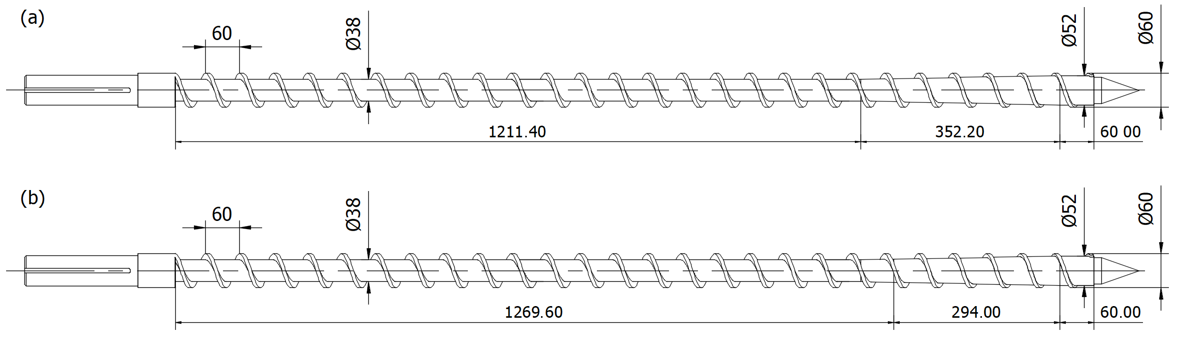
The research program included scaling-up from the reference extruder using a screw of diameter D = 45 mm to the target extruder using a screw of diameter D = 60 mm while keeping the length/diameter (L/D) ratio constant. Scaling up has been performed for both flood-fed and starve-fed extrusion, the process variables of which were determined from process optimization (Section 3.2). Screw geometry parameters of the target extruder for flood-fed extrusion and starve-fed extrusion are presented in Figure 22 and displayed in Table 3.
Figure 22.
Geometry of the target extruder: (a) flood-fed process and (b) starve-fed process.
Table 3.
Screw geometry.
The results of the simulation for the reference extruder at optimal process variables are shown in Figure 14 and Figure 15.
Scaling-up was performed in the same range (as in process optimization) of input variables of screw speed ν = 40 ÷ 120 rpm and cylinder temperatures ΘI = 150 °C, ΘII = 180 ÷ 250 °C, ΘIII = 180 ÷ 250 °C, ΘIV = 180 ÷ 250 °C. It was carried out according to the criteria of single parameters of specific energy use εs, melt temperature Θmelt, and melting length Lmelting (the ratio of the screw length needed for material plasticization to the total screw length), and according to the functional criteria of the temperature distribution and plasticization profile.
The global objective function was expressed as:
where ϕi s represents the global objective function, εs A represents the specific energy use in the reference extruder, εs B i represents the specific energy use in the target extruder, Θmelt A represents the temperature at the die outlet in the reference extruder, Θmelt B I represents the temperature at the die outlet in the target extruder, Lmelting A represents the melting length in the reference extruder, Lmelting B i represents the melting length in the target extruder, ΘA represents the temperature in the reference extruder, ΘB i represents the temperature in the target extruder, SBPA represents the plasticization profile in the reference extruder, SBPB i represents the plasticization profile in the target extruder, i represents the number of the next value from the variables set, and n represents the number of the next value in the profile.
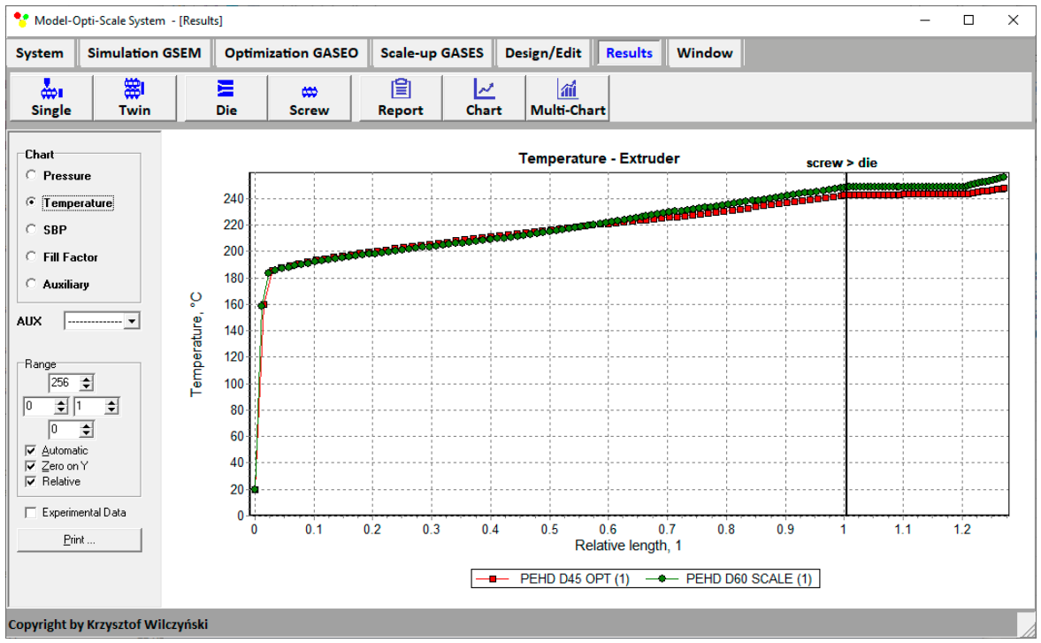
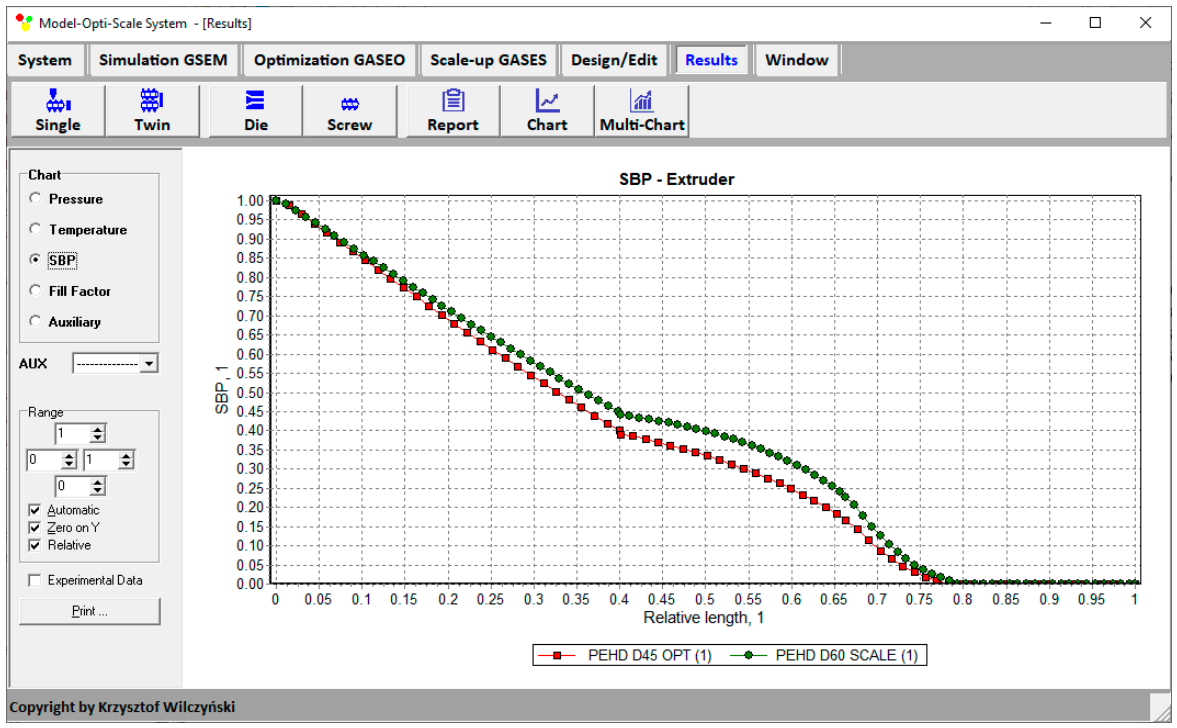
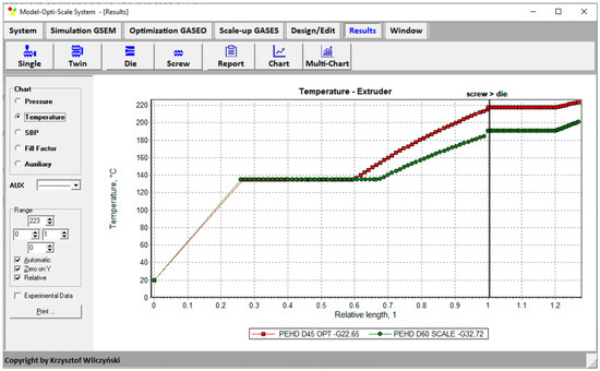
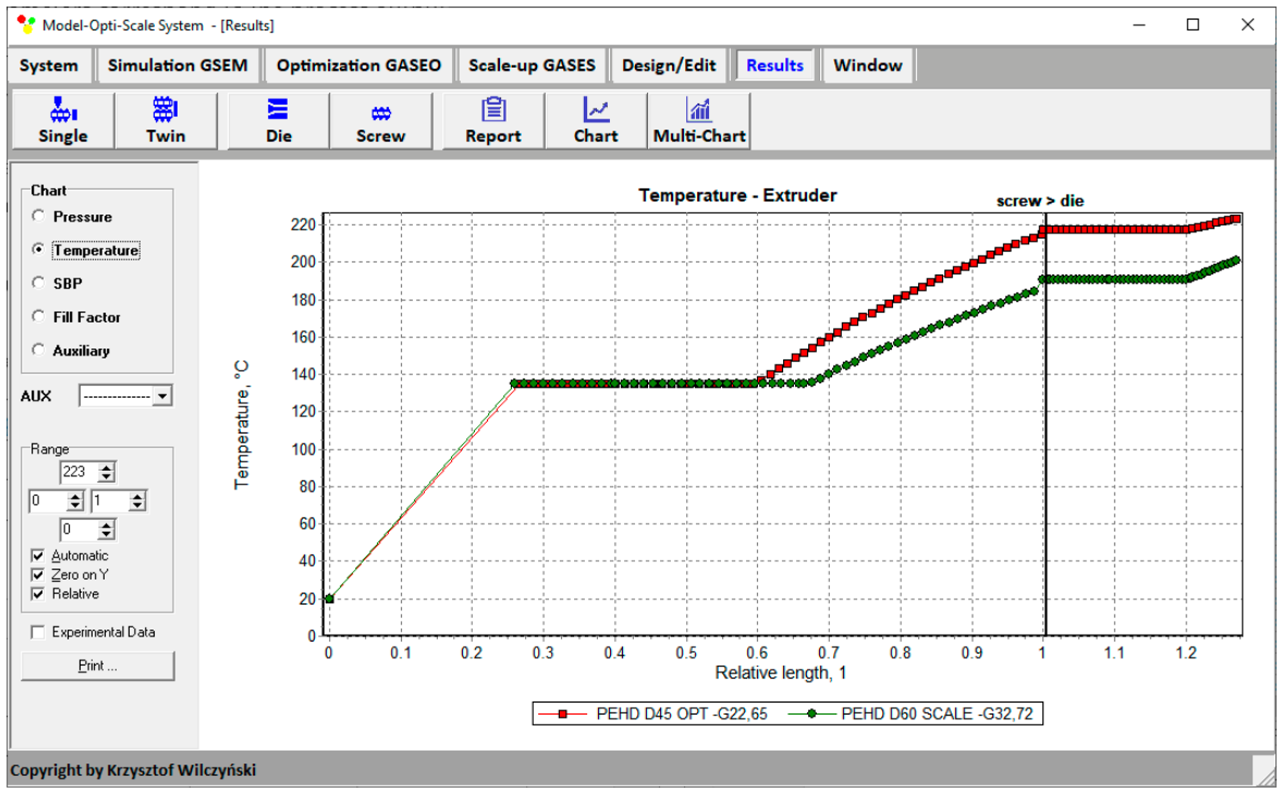
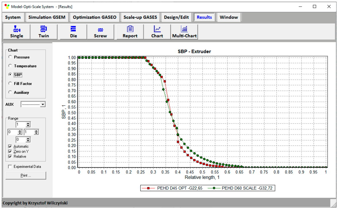
The scaling results for flood-fed extrusion are summarized in Table 4 and presented in Figure 23 and Figure 24. The smallest value of the objective function (Equation (7)), i.e., the minimum difference between the variables of the reference and target extrusion, was obtained at a screw speed of ν = 55.48 rpm for the cylinder temperatures: ΘI = 150 °C, ΘII = 180 °C, ΘIII = 198.06 °C, and ΘIV = 204.84 °C. These data correspond to the process output variables of flow rate G = 32.72 kg/h, specific energy use εs = 469.05 kJ/kg, and melt temperature Θmelt = 247.77 °C, as well as melting length Lmelting = 0.784. The differences between the reference and target variables are small (Table 4). Therefore, it can be stated that these processes are similar in terms of the assumed criteria. The distributions of temperature and plasticization are also similar, as shown in Table 4 and Figure 23 and Figure 24. By enlarging the extrusion scale, substantial growth in the extrusion output was achieved (44.46%).
Table 4.
Scaling-up results of flood-fed extrusion.
Figure 23.
Temperature distribution for flood-fed extrusion. Red line—reference extruder; green line—target extruder.
Figure 24.
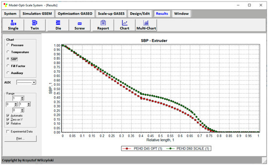
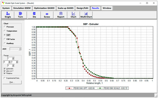
Solid bed profile (SBP) for flood-fed extrusion. Red line—reference extruder; green line—target extruder.
The scaling results for starve-fed extrusion are summarized in Table 5 and presented in Figure 25 and Figure 26. The smallest value of the objective function (Equation (7)), i.e., the minimum difference between the parameters of the reference and target extrusion, was obtained at a screw speed of ν = 57.14 rpm for the cylinder temperatures: ΘI = 150 °C, ΘII = 198.06 °C, ΘIII = 198.06 °C, and ΘIV = 191.29 °C. These data correspond to the process output variables of flow rate G = 32.72 kg/h, specific energy use εs = 437.35 kJ/kg, and melt temperature Θmelt = 216.98 °C, as well as melting length Lmelting = 0.633. The differences between the reference variables and target variables are small (Table 5). Therefore, it can be stated that these processes are similar in terms of the assumed criteria. The distributions of temperature and plasticization are also similar and are shown in Table 5 and Figure 25 and Figure 26. By enlarging the extrusion scale, a substantial growth in extrusion output was achieved (49.13%).
Table 5.
Scaling-up results of starve-fed extrusion.
Figure 25.
Temperature distribution for starve-fed extrusion. Red line—reference extruder; green line—target extruder.
Figure 26.
Solid bed profile (SBP) for starve-fed extrusion. Red line—reference extruder; green line—target extruder.
4. Summary and Conclusions
This paper presents an integrated Model-Opti-Scale (MOPS) system developed for computer-aided design of single-screw plastics extrusion. The system integrates process modeling, optimization, and scaling-up within a single computational environment, enabling comprehensive analysis of the extrusion process under both flood-fed and starve-fed operating conditions.
As part of this work, the global extrusion model GSEM (Global Screw Extrusion Model) was developed and applied to simulate the material solid and melt conveying, as well as material plasticization in the screw/die system. The model enabled determination of the fundamental process characteristics, such as pressure and temperature profiles, material plasticization profile, screw filling profile, extrusion throughput, and energy consumption. The applied computational algorithms allowed for the analysis of the process both for fully filled screw channels and for partially filled conditions, characteristic of starve-fed extrusion.
Based on the simulation results, a multi-objective optimization of the extrusion process was carried out using the GASEO (Genetic Algorithms Screw Extrusion Optimization) program based on Genetic Algorithms. The investigations included analysis of the influence of technological and geometrical screw parameters, particularly screw rotational speed and metering/transition region lengths, on the extrusion process performance. The optimization criteria included maximizing process throughput and minimizing specific energy consumption. The obtained results confirmed the possibility of effectively identifying compromise solutions between process efficiency and system energy consumption.
For the weighting combinations and operating conditions considered in this study, the optimum corresponded to flood-fed operation when throughput was assigned the dominant weight. In contrast, starve-fed operation was selected when throughput and specific energy consumption were assigned equal weights.
The two weighting combinations and assumed in these studies should be regarded as illustrative cases demonstrating the multi-criteria optimization capabilities of the MOPS system. They do not provide an exhaustive characterization of the trade-off between throughput and specific energy consumption and should not be interpreted as defining a complete Pareto front.
The performed analyses demonstrated the extensive capabilities of the system for carrying out the comprehensive optimization studies that would be practically impossible to realize experimentally. Owing to the application of binary coding of process parameters and Genetic Algorithms, it was possible to analyze a large number of geometrical and technological configurations of the extrusion process while keeping a reasonable computational time.
The crucial novelty of this paper is the development of an integrated computational architecture in which the modeling, optimization, and scaling of the extrusion process are performed sequentially and in an interconnected manner. A particularly innovative element is the uniform treatment of flood-fed and starve-fed processes, the ability to seamlessly transition between these feeding methods, and the simultaneous optimization of both feeding methods. In this case, the choice of flood-fed or starve-fed is not imposed by the user but rather results from the optimization process. The resulting optimal process can then be directly scaled according to both scalar criteria and entire process profiles. Such a comprehensive combination of these functionalities has not been available in a single computer system so far.
In conclusion, the authors consider extending the holistic approach to modeling the polymer processing used in this work to the injection molding process. They are inspired by Donovan’s studies [130], according to which “the screw recharge in the injection molding is the transient plasticizing process, which gradually approached the equilibrium extrusion as the screw rotated. If screw rotation accounted for a large portion of the whole cycle time, plasticizing is similar to the extrusion, but if the screw rotation accounted for a small portion of the whole cycle time, plasticizing is significantly different”. As such, the authors believe it is worth the work.
Author Contributions
Conceptualization, K.W.; methodology, K.W.; software, A.N.; investigation, A.N.; writing—original draft preparation, K.W.; writing—review and editing, K.W.; visualization, A.N.; supervision, K.W.; resources, K.W. and A.N.; data curation, A.N. All authors have read and agreed to the published version of the manuscript.
Funding
This research received no external funding.
Institutional Review Board Statement
Not applicable.
Informed Consent Statement
Not applicable.
Data Availability Statement
The original contributions presented in this study are included in the article. Further inquiries can be directed to the corresponding author.
Conflicts of Interest
The authors declare no conflicts of interest.
References
- Fisher, E.G. Extrusion of Plastics, 1st ed.; Iliffe Books Ltd.: London, UK, 1958. [Google Scholar]
- McKelvey, J.M. Polymer Processing; John Wiley & Sons Inc.: New York, NY, USA, 1962. [Google Scholar]
- Schenkel, G. Kunststoff-Extrudertechnik; Carl Hanser Verlag: Munich, Germany, 1963. [Google Scholar]
- Pearson, J.R.A. Mechanical Principles of Polymer Melt Processing; Pergamon Press: Oxford, UK, 1966. [Google Scholar]
- Tadmor, Z.; Klein, I. Engineering Principles of Plasticating Extrusion; Van Nostrand Reinhold Co.: New York, NY, USA, 1970. [Google Scholar]
- Fenner, R.T. Extruder Screw Design; Iliffe Books Ltd.: London, UK, 1970. [Google Scholar]
- Torner, R.V. Grundprozesse der Verarbeitung von Polymeren; VEB Deutscher Verlag: Leipzig, Germany, 1974. [Google Scholar]
- Middleman, S. Fundamentals of Polymer Processing; McGraw-Hill: New York, NY, USA, 1977. [Google Scholar]
- Hensen, F.; Knappe, W.; Potente, H. Handbuch der Kunststoff-Extrusiontechnik. Grundlagen; Carl Hanser Verlag: Munich, Germany, 1989. [Google Scholar]
- White, J.L. Rubber Processing; Hanser Publishers: Munich, Germany, 1995. [Google Scholar]
- Baird, D.G.; Collias, D.I. Polymer Processing: Principles and Design; Butterworth-Heinemann: Oxford, UK, 1995. [Google Scholar]
- Stevens, M.J.; Covas, J.A. Extruder Principles and Operation; Springer: Berlin/Heidelberg, Germany, 1995. [Google Scholar]
- Wilczyński, K. Reologia w przetwórstwie tworzyw sztucznych. In Rheology in Polymer Processing; Wydawnictwa Naukowo-Techniczne, Scientific and Technical Publishers: Warsaw, Poland, 2001. [Google Scholar]
- White, J.L.; Potente, H. Screw Extrusion. Science and Technology; Hanser Publishers: Munich, Germany, 2003. [Google Scholar]
- Tadmor, Z.; Gogos, C.G. Principles of Polymer Processing, 2nd ed.; John Wiley & Sons Inc.: New York, NY, USA, 2006. [Google Scholar]
- Osswald, T.; Hernandez-Ortiz, J.P. Polymer Processing. Modeling and Simulation; Carl Hanser Verlag: Munich, Germany, 2006. [Google Scholar]
- Kohlgrüber, K. Co-Rotating Twin-Screw Extruders; Hanser Publisher: New York, NY, USA, 2008. [Google Scholar]
- White, J.L.; Kim, E.K. Twin Screw Extrusion. Technology and Principles, 2nd ed.; Hanser Publishers: Munich, Germany, 2010. [Google Scholar]
- Chung, C.I. Extrusion of Polymers. Theory and Practice, 2nd ed.; Carl Hanser Verlag: Munich, Germany, 2010. [Google Scholar]
- Vlachopoulos, J. Polymer Rheology and Extrusion; McMaster University: Hamilton, ON, Canada, 2011. [Google Scholar]
- Campbell, G.A.; Spalding, M.A. Analyzing and Troubleshooting Single-Screw Extruders; Carl Hanser Verlag: Munich, Germany, 2013. [Google Scholar]
- Rauwendaal, C. Polymer Extrusion, 5th ed.; Carl Hanser Verlag: Munich, Germany, 2014. [Google Scholar]
- Agassant, J.F.; Avenas, P.; Carreau, P.J.; Vergnes, B.; Vincent, M. Polymer Processing. Principles and Modelling, 2nd ed.; Carl Hanser Verlag: Munich, Germany, 2017. [Google Scholar]
- Vlachopoulos, J.; Polychronopoulos, N.D. Understanding Rheology and Technology of Polymer Extrusion; Polydynamics Inc.: Dundas, ON, Canada, 2019. [Google Scholar]
- Wilczyński, K. Rheology in Polymer Processing. Modeling and Simulation; Carl Hanser Verlag: Munich, Germany, 2021. [Google Scholar]
- Rowell, H.S.; Finlayson, D. Screw Viscous Pumps. Engineering 1928, 126, 249. [Google Scholar]
- Carley, J.F.; Mallouk, R.S.; McKelvey, J.M. Simplified Flow Theory for Screw Extruders. Ind. Eng. Chem. 1953, 45, 974–978. [Google Scholar] [CrossRef] [Scilit]
- Marschik, C.; Roland, W.; Löw-Baselli, B.; Miethlinger, J. A Heuristic Method for Modeling Three-Dimensional Non-Newtonian Flows of Polymer Melts in Single-Screw Extruders. J. Non-Newton. Fluid 2017, 248, 27–39, Erratum in J. Non-Newton. Fluid 2018, 252, 57. [Google Scholar] [CrossRef] [Scilit]
- Marschik, C.; Roland, W.; Osswald, T.A. Melt Conveying in Single-Screw Extruders: Modeling and Simulation. Polymers 2022, 14, 875. [Google Scholar] [CrossRef] [Scilit] [PubMed]
- Marschik, C.H.; Roland, W.; Kommenda, M. Extended Melt-Conveying Models for Single-Screw Extruders: Integrating Domain Knowledge into Symbolic Regression. Polym. Eng. Sci. 2023, 63, 1. [Google Scholar] [CrossRef] [Scilit]
- Darnell, W.H.; Mol, E.A.J. Solids Conveying in Extruders. SPE-J. 1956, 20, 20–29. [Google Scholar]
- Campbell, G.A.; Dontula, N. Solids Transport in Extruders. Int. Polym. Process. 1995, 10, 30–35. [Google Scholar] [CrossRef] [Scilit]
- Hyun, K.S.; Spalding, M.A.; Hinton, C.E. Theoretical and Experimental Analysis of Solids Conveying in Single-Screw Extruders. J. Reinf. Plast. Compos. 1997, 16, 1210–1219. [Google Scholar] [CrossRef] [Scilit]
- Fang, S.; Chen, L.; Zhu, F. Studies on the Theory of Single Screw Plasticating Extrusion. Part II: Non-Plug Flow Solid Conveying. Polym. Eng. Sci. 1991, 31, 1117–1122. [Google Scholar] [CrossRef] [Scilit]
- Moysey, P.A.; Thompson, M.R. Investigation of Solids Transport in a Single-Screw Extruder Using a 3-D Discrete Particle Simulation. Polym. Eng. Sci. 2004, 44, 2203–2215. [Google Scholar] [CrossRef] [Scilit]
- Moysey, P.A.; Thompson, M.R. Discrete Particle Simulations of Solids Compaction and Conveying in a Single-Screw Extruder. Polym. Eng. Sci. 2008, 48, 62–73. [Google Scholar] [CrossRef] [Scilit]
- Trippe, J.; Schöppner, V. Modeling of Solid Conveying Pressure Throughput Behavior of Single Screw Smooth Barrel Extruders under Consideration of Backpressure and High Screw Speeds. Int. Polym. Process. 2018, 33, 486–496. [Google Scholar] [CrossRef] [Scilit]
- Scharr, K.; Schöppner, V. Phenomenon-Oriented Investigation of the Solid Conveying Zones of Co-Rotating Twin Screw Extruders Using DEM-Simulations. Z. Kunststofftechnik 2017, 13, 196. [Google Scholar] [CrossRef] [Scilit]
- Maddock, B.H. A Visual Analysis of Flow and Mixing in Extruder Screws. SPE ANTEC Tech. Pap. 1959, 15, 383. [Google Scholar]
- Street, L.F. Plastifying Extrusion. Int. Plast. Eng. 1961, 1, 289–296. [Google Scholar]
- Tadmor, Z. Fundamentals of Plasticating Extrusion. I. A Theoretical Model for Melting. Polym. Eng. Sci. 1966, 6, 185–190. [Google Scholar] [CrossRef] [Scilit]
- Tadmor, Z.; Duvdevani, I.J.; Klein, I. Melting in Plasticating Extruders Theory and Experiments. Polym. Eng. Sci. 1967, 7, 198–217. [Google Scholar] [CrossRef] [Scilit]
- Tadmor, Z.; Klein, I. Computer Programs for Plastic Engineers; Reinhold Book Corporation: New York, NY, USA, 1968. [Google Scholar]
- Halmos, A.L.; Pearson, J.R.A.; Trottnow, R. Melting in Single Screw Extruders. Polymer 1978, 19, 1199–1216. [Google Scholar] [CrossRef] [Scilit]
- Cox, A.P.D.; Fenner, R.T. Melting Performance in the Single Screw Extrusion of Thermoplastics. Polym. Eng. Sci. 1980, 20, 562–571. [Google Scholar] [CrossRef] [Scilit]
- Elbirli, B.; Lindt, J.T.; Gottgetreu, S.R.; Baba, S.M. Mathematical Modeling of Melting of Polymers in Barrier-Screw Extruders. Polym. Eng. Sci. 1983, 23, 86–94. [Google Scholar] [CrossRef] [Scilit]
- Agur, E.E.; Vlachopoulos, J. Numerical Simulation of a Single-Screw Plasticating Extruder. Polym. Eng. Sci. 1982, 22, 1084–1094. [Google Scholar] [CrossRef] [Scilit]
- Sebastian, D.H.; Rakos, R. Extrusion Process Analysis with PASS. In Computer Modeling for Extrusion and Other Continuous Polymer Processes; O’Brien, K.T., Ed.; Hanser Publishers: New York, NY, USA, 1992; Chapter 7; pp. 331–448. [Google Scholar]
- Potente, H.; Hanhart, W.; Schöppner, V. Potential Applications for Computer-aided Extruder Design. Int. Polym. Process. 1993, 8, 335–344. [Google Scholar] [CrossRef] [Scilit]
- Wilczyński, K. A Computer Model for Single-Screw Plasticating Extrusion. Polym.-Plast. Technol. 1996, 35, 449–477. [Google Scholar] [CrossRef] [Scilit]
- Wilczyński, K. Single Screw Extrusion Model for Plasticating Extruders. Polym.-Plast. Technol. 1999, 38, 581–608. [Google Scholar] [CrossRef] [Scilit]
- Wilczyński, K.J.; Lewandowski, A.; Nastaj, A.; Wilczyński, K. Modeling for Starve Fed/Flood Fed Mixing Single-Screw Extruders. Int. Polym. Process. 2016, 31, 82–91. [Google Scholar] [CrossRef] [Scilit]
- Wilczyński, K.; Tyszkiewicz, A.; Szymaniak, Z. Modeling for Morphology Development during Single-Screw Extrusion of LDPE/PS Blend. J. Mater. Process. Technol. 2001, 109, 320–323. [Google Scholar] [CrossRef] [Scilit]
- Wilczyński, K.; Nastaj, A.; Lewandowski, A.; Wilczyński, K.J.; Buziak, K. Experimental Study for Extrusion of Polypropylene/Wood Flour Composites. Int. Polym. Process. 2015, 30, 113–120. [Google Scholar] [CrossRef] [Scilit]
- Wilczyński, K.; Buziak, K.; Wilczyński, K.J.; Lewandowski, A.; Nastaj, A. Computer Modeling for Single-Screw Extrusion of Wood-Plastic Composites. Polymers 2018, 10, 295. [Google Scholar] [CrossRef] [Scilit] [PubMed]
- Wilczyński, K.; Buziak, K.; Lewandowski, A.; Nastaj, A.; Wilczyński, K.J. Rheological Basics for Modeling of Extrusion Process of Wood Polymer Composites. Polymers 2021, 13, 622. [Google Scholar] [CrossRef] [Scilit] [PubMed]
- Fukase, H.; Kunio, T.; Shinya, S.; Nomura, A. A Plasticating Model for Single-Screw Extruders. Polym. Eng. Sci. 1982, 22, 578–586. [Google Scholar] [CrossRef] [Scilit]
- Zawadsky, E.; Karnis, J. Mathematical Model of a Single-Screw Plasticating Extruder. J. Rheol. Acta 1985, 24, 556–565. [Google Scholar] [CrossRef] [Scilit]
- Vincelette, A.R.; Guerrero, C.S.; Carreau, P.J.; Lafleur, P.G. A Model for Single-Screw Plasticating Extruders. Int. Polym. Process. 1989, 4, 232–241. [Google Scholar] [CrossRef] [Scilit]
- White, J.L.; Chen, Z. Simulation of Non-Isothermal Flow in Modular Co-Rotating Twin Screw Extrusion. Polym. Eng. Sci. 1994, 34, 229–237. [Google Scholar] [CrossRef] [Scilit]
- Bawiskar, S.; White, J.L. Solids Conveying and Melting in a Starve Fed Self-wiping Co-Rotating Twin Screw Extruder. Int. Polym. Process. 1995, 10, 105–110. [Google Scholar] [CrossRef] [Scilit]
- Bawiskar, S.; White, J.L. A Composite Model for Solid Conveying, Melting, Pressure and Fill Factor Profiles in Modular Co-Rotating Twin Screw Extruders. Int. Polym. Process. 1997, 12, 331–340. [Google Scholar] [CrossRef] [Scilit]
- Bawiskar, S.; White, J.L. Melting Model for Modular Self Wiping Co-Rotating Twin Screw Extruders. Polym. Eng. Sci. 1998, 38, 727–740. [Google Scholar] [CrossRef] [Scilit]
- Potente, H.; Ansalh, J.; Klarholz, B. Design of Tightly Intermeshing Co-Rotating Twin Screw Extruders. Int. Polym. Process. 1994, 9, 11–25. [Google Scholar] [CrossRef] [Scilit]
- Potente, H.; Melisch, U. Theoretical and Experimental Investigations of the Melting of Pellets in Co-Rotating Twin-Screw Extruders. Int. Polym. Process. 1996, 11, 101–108. [Google Scholar] [CrossRef] [Scilit]
- Potente, H.; Bastian, M.; Flecke, J. Design of a Compounding Extruder by Means of the SIGMA Simulation Software. Adv. Polym. Technol. 1999, 18, 147–170. [Google Scholar] [CrossRef]
- Vergnes, B.; Valle, G.D.; Delamare, L. A Global Computer Software for Polymer Flows in Corotating Twin Screw Extruders. Polym. Eng. Sci. 1998, 38, 1781–1792. [Google Scholar] [CrossRef] [Scilit]
- Hong, M.-H.; White, J.L. Fluid Mechanics of Intermeshing Counter-Rotating Twin Screw Extruders. Int. Polym. Process. 1998, 13, 342–346. [Google Scholar] [CrossRef] [Scilit]
- Hong, M.H.; White, J.L. Simulation of Flow in an Intermeshing Modular Counter-Rotating Twin Screw Extruder: Non-Newtonian and Non-Isothermal Behavior. Int. Polym. Process. 1999, 14, 136–143. [Google Scholar] [CrossRef] [Scilit]
- Wilczyński, K.; White, J.L. Experimental Study of Melting in an Intermeshing Counter-Rotating Twin Screw Extruder. Int. Polym. Process. 2001, 16, 257–262. [Google Scholar] [CrossRef] [Scilit]
- Wilczyński, K.; White, J.L. Melting Model for Intermeshing Counter-Rotating Twin-Screw Extruders. Polym. Eng. Sci. 2003, 43, 1715–1726. [Google Scholar] [CrossRef] [Scilit]
- Wilczyński, K.; Jiang, Q.; White, J.L. A Composite Model for Melting, Pressure and Fill Factor Profiles in a Metered Fed Closely Intermeshing Counter-Rotating Twin Screw Extruder. Int. Polym. Process. 2007, 22, 198–203. [Google Scholar] [CrossRef] [Scilit]
- Wilczyński, K.; White, J.L. Modeling of twin-screw extrusion. Part I. A model of counter-rotating extrusion. Polimery 2008, 53, 754–759. [Google Scholar] [CrossRef] [Scilit]
- Wilczyński, K.; Nastaj, A.; Lewandowski, A.; Wilczyński, K.J. Modeling of the Polymer Melt Flow in a Twin Screw Counter Rotating Extrusion Process. Part II. Simulation and Experimental Studies—Verification of the Adopted Model. Polimery 2011, 56, 45–50. [Google Scholar] [CrossRef] [Scilit]
- Wilczyński, K.; Lewandowski, A.; Wilczyński, K.J. Experimental Study of Melting of LDPE/PS Polyblend in an Intermeshing Counter-Rotating Twin Screw Extruder. Polym. Eng. Sci. 2012, 52, 449–458. [Google Scholar] [CrossRef] [Scilit]
- Wilczyński, K.; Lewandowski, A. Study on the Polymer Melt Flow in a Closely Intermeshing Counter-Rotating Twin Screw Extruder. Int. Polym. Process. 2014, 29, 649–659. [Google Scholar] [CrossRef] [Scilit]
- Lewandowski, A.; Wilczyński, K.J.; Nastaj, A.; Wilczyński, K. A composite model for an intermeshing counter-rotating twin-screw extruder and its experimental verification. Polym. Eng. Sci. 2015, 55, 2838–2848. [Google Scholar] [CrossRef] [Scilit]
- Thompson, M.R.; Donoian, G.; Christiano, J.P. Melting Mechanism of a Starved-Fed Single-Screw Extruder for Calcium Carbonate Filled Polyethylene. Polym. Eng. Sci. 2000, 40, 2014–2026. [Google Scholar] [CrossRef] [Scilit]
- Wilczyński, K.; Lewandowski, A.; Wilczyński, K.J. Experimental Study for Starve-Fed Single Screw Extrusion of Thermoplastics. Polym. Eng. Sci. 2012, 52, 1258–1270. [Google Scholar] [CrossRef] [Scilit]
- Wilczyński, K.; Nastaj, A.; Wilczyński, K.J. Melting Model for Starve Fed Single Screw Extrusion of Thermoplastics. Int. Polym. Process. 2013, 28, 34–42. [Google Scholar] [CrossRef] [Scilit]
- Wilczyński, K.J.; Nastaj, A.; Lewandowski, A.; Wilczyński, K. A Composite Model for Starve Fed Single Screw Extrusion of Thermoplastics. Polym. Eng. Sci. 2014, 54, 2362–2374. [Google Scholar] [CrossRef] [Scilit]
- Wilczyński, K.J. Experimental and Theoretical Study on Screw Filling in Starve Fed Single Screw Extruders. Int. Polym. Process. 2018, 33, 171–179. [Google Scholar] [CrossRef] [Scilit]
- Wilczyński, K.J.; Lewandowski, A.; Nastaj, A.; Wilczyński, K. A Global Model for Starve-Fed Nonconventional Single-Screw Extrusion of Thermoplastics. Adv. Polym. Technol. 2017, 36, 23–35. [Google Scholar] [CrossRef] [Scilit]
- Wilczyński, K.J.; Lewandowski, A.; Wilczyński, K. Experimental Study of Melting of Polymer Blends in a Starve Fed Single Screw Extruder. Polym. Eng. Sci. 2016, 56, 1349–1356. [Google Scholar] [CrossRef] [Scilit]
- Wilczyński, K.J.; Nastaj, A.; Wilczyński, K. A Computer Model for Starve-Fed Single-Screw Extrusion of Polymer Blends. Adv. Polym. Technol. 2018, 37, 2142–2151. [Google Scholar] [CrossRef] [Scilit]
- Wilczyński, K.; Buziak, K.; Bartnik, M. Study on the Flow of Wood-Plastic Composites in the Single-Screw Extrusion Process/Badanie przeplywu kompozytow polimerowo-drzewnych w procesie wytlaczania jednoślimakowego. Polimery 2016, 61, 195–201. [Google Scholar] [CrossRef] [Scilit]
- Wilczyński, K.J.; Buziak, K. Badanie przep3ywu kompozytów polimerowo-drzewnych w procesie wytłaczania jednoślimakowego/Study on the Flow of Wood Plastic Composites in the Starve Fed Single Screw Extrusion. Polimery 2017, 62, 680–685. [Google Scholar] [CrossRef] [Scilit]
- Wilczyński, K.J.; Nastaj, A.; Buziak, K. Modeling of Starve-Fed Single Screw Extrusion of Wood-Polymer Composites / Modelowanie procesu wytłaczania jednoślimakowego z dozowanym zasilaniem polimerowych kompozytów drzewnych. Polimery 2018, 63, 542–548. [Google Scholar] [CrossRef] [Scilit]
- Wilczyński, K.J.; Buziak, K. A Computer Model of Starve Fed Single Screw Extrusion of Wood Plastic Composites. Polymers 2021, 13, 1252. [Google Scholar] [CrossRef] [Scilit] [PubMed]
- Lopez-Latorre, L.; McKelvey, J.M. Melting and Pressurization in Starve Feed Extrusion. Adv. Polym. Technol. 1984, 3, 355–364. [Google Scholar] [CrossRef] [Scilit]
- Isherwood, D.P.; Pieris, R.N.; Kassatly, J. The Effect of Metered Starve Feeding on the Performance of a Small Extruder. J. Eng. Ind. 1984, 106, 132–136. [Google Scholar] [CrossRef] [Scilit]
- Strand, S.R.; Spalding, M.A.; Hyun, S.K. Modeling of the Solids-Conveying Section of a Starve Fed Single Screw Plasticating Extruder. SPE ANTEC Tech. Pap. 1992, 38, 2537–2541. [Google Scholar]
- Gale, M. Compounding with Single-Screw Extruders. Adv. Polym. Technol. 1997, 16, 251–262. [Google Scholar] [CrossRef]
- Ariffin, A.; Ahmad, M.S.B. Review: Single Screw Extruder in Particulate Filler Composite. Polym.-Plast. Technol. 2011, 50, 395–403. [Google Scholar] [CrossRef] [Scilit]
- Teixeira, C.; Gaspar-Cunha, A.; Covas, J.A. Flow and Heat Transfer Along the Length of a Co-rotating Twin Screw Extruder. Polym.-Plast. Technol. 2012, 51, 1567–1577. [Google Scholar] [CrossRef] [Scilit]
- Malik, M.; Kalyon, D.M.; Golba, J.C., Jr. Simulation of Co-Rotating Twin Screw Extrusion Process Subject to Pressure-Dependent Wall Slip at Barrel and Screw Surfaces: 3D FEM Analysis for Combinations of Forward- and Reverse-Conveying Screw Elements. Int. Polym. Process. 2014, 29, 51–62. [Google Scholar] [CrossRef] [Scilit]
- Wilczyński, K.; Nastaj, A.; Lewandowski, A.; Wilczyński, K.J. Multipurpose Computer Model for Screw Processing of Plastics. Polym.-Plast. Technol. 2012, 51, 626–633. [Google Scholar] [CrossRef] [Scilit]
- Wilczyński, K.; Nastaj, A.; Lewandowski, A.; Wilczyński, K.J.; Buziak, K. Fundamentals of Global Modeling for Polymer Extrusion. Polymers 2019, 11, 2106. [Google Scholar] [CrossRef] [Scilit] [PubMed]
- Underwood, W.M. Experimental Method for Designing Extrusion Screws. Chem. Eng. Prog. 1962, 58, 59. [Google Scholar]
- Verbraak, C.P.J.M.; Meijer, H.E.H. Screw Design in Injection Molding. Polym. Eng. Sci. 1989, 29, 479–487. [Google Scholar] [CrossRef] [Scilit]
- Maddock, B.H.; Smith, D.J. Extruder Design by Computer Printout. SPE J. 1972, 28, 12–17. [Google Scholar]
- Helmy, H.A.A.; Parnaby, J. Computer—Aided Optimal Melt Screw Design. Polym. Eng. Sci. 1976, 16, 437–449. [Google Scholar] [CrossRef] [Scilit]
- Potente, H.; Hanhart, W.; Reski, T. Design and Processing Optimization of Extruder Screws. Polym. Eng. Sci. 1994, 34, 937–945. [Google Scholar] [CrossRef] [Scilit]
- Thibodeau, C.A.; Lafleur, P.G. Computer Design and Screw Optimization. In Proceedings of the Polymer Processing Society 16th Annual Meeting (PPS-16), Shanghai, China, 18–23 June 2000; p. 15. [Google Scholar]
- Covas, J.A.; Cunha, A.G.; Oliveira, P. An Optimization Approach to Practical Problems in Plasticating Single Screw Extrusion. Polym. Eng. Sci. 1999, 39, 443–456. [Google Scholar] [CrossRef] [Scilit]
- Gaspar-Cunha, A.; Covas, J.A. The Design of Extrusion Screw: An Optimization Approach. Int. Polym. Process. 2001, 16, 229–240. [Google Scholar] [CrossRef] [Scilit]
- Gaspar-Cunha, A.; Poulesquen, A.; Vergnes, B.; Covas, J.A. Optimization of Processing Conditions for Polymer Twin-Screw Extrusion. Int. Polym. Process. 2002, 17, 201–213. [Google Scholar] [CrossRef] [Scilit]
- Gaspar-Cunha, A.; Covas, J.; Vergnes, B. Defining the Configuration of Co-Rotating Twin-Screw Extruders with Multiobjective Evolutionary Algorithms. Polym. Eng. Sci. 2005, 45, 1159–1173. [Google Scholar] [CrossRef] [Scilit]
- Nastaj, A.; Wilczyński, K. Optimization for Starve Fed/Flood Fed Single Screw Extrusion of Polymeric Materials. Polymers 2020, 12, 149. [Google Scholar] [CrossRef] [Scilit] [PubMed]
- Nastaj, A.; Wilczyński, K. Optimization for the Contrary-Rotating Double-Screw Extrusion of Plastics. Polymers 2023, 15, 1489. [Google Scholar] [CrossRef] [Scilit] [PubMed]
- Nastaj, A.; Wilczyński, K. Optimization and Scale-Up for Polymer Extrusion. Polymers 2021, 13, 1547. [Google Scholar] [CrossRef] [Scilit] [PubMed]
- Carley, J.F.; McKelvey, J.M. Extruder Scale-Up Theory and Experiments. Ind. Eng. Chem. 1953, 45, 989–992. [Google Scholar] [CrossRef] [Scilit]
- Maddock, B.H. Extruder Scale-up by Computer. Polym. Eng. Sci. 1974, 14, 853–858. [Google Scholar] [CrossRef] [Scilit]
- Yi, B.; Fenner, R.T. Scaling-up Plasticating Screw Extruders on the Basis of Similar Melting Performances. Plast. Rubber Process. 1976, 1, 119–123. [Google Scholar]
- Pearson, J.R.A. Scale-up of Single Screw Extruders for Polymer Processing. Plast. Rubber Process. 1976, 1, 113–118. [Google Scholar]
- Potente, H.; Fischer, P. Model Laws for the Design of Single Screw Plasticating Extruders. Kunststoffe 1977, 67, 242–247. [Google Scholar]
- Schenkel, G. Extruder Series with Variable L/D Ratios. Kunststoffe 1978, 68, 155–162. [Google Scholar]
- Chung, C.I. On the Scale-up of Plasticating Extruder Screws. Polym. Eng. Sci. 1984, 24, 626–632. [Google Scholar] [CrossRef] [Scilit]
- Rauwendaal, C. Scale-up of Single Screw Extruders. Polym. Eng. Sci. 1987, 27, 1059–1068. [Google Scholar] [CrossRef] [Scilit]
- Potente, H. Existing Scale-Up Rules for Single-Screw Plasticating Extruders. Int. Polym. Process. 1991, 6, 267–278. [Google Scholar] [CrossRef] [Scilit]
- Potente, H. Scale-up of Mixing Equipments. In Mixing and Compounding of Polymers, 2nd ed.; Manas-Zloczower, I., Ed.; Carl Hanser Verlag: Munich, Germany, 2009; pp. 577–643. [Google Scholar]
- Covas, J.A.; Gaspar-Cunha, A. Extrusion Scale-up: An Optimization-based Methodology. Int. Polym. Process. 2009, 24, 67–82. [Google Scholar] [CrossRef] [Scilit]
- Covas, J.A.; Gaspar-Cunha, A. A Scaling-up Methodology for Co-rotating Twin-Extruders. In Proceedings of the 27th Annual Meeting of the Polymer Processing Society (PPS-27), Marrakesh, Morocco, 10–14 May 2011; pp. 1–6. [Google Scholar]
- Gaspar-Cunha, A.; Covas, J.A. An Engineering Scale-Up Approach Using Multi-Objective Optimization. Int. J. Nat. Comput. Res. 2014, 4, 17–30. [Google Scholar] [CrossRef] [Scilit]
- Denysiuk, R.; Recio, G.; Covas, J.A.; Gaspar-Cunha, A. Using Multi-objective Optimization Algorithms and Decision Making Support to Solve Polymer Extrusion Problems. Polym. Eng. Sci. 2018, 58, 493–502. [Google Scholar] [CrossRef] [Scilit]
- Berzin, F.; David, C.; Vergnes, B. Optimization and Scale-Up of Twin-Screw Reactive Extrusion: The Case of EVA Transesterification. Int. Polym. Process. 2020, 35, 422–428. [Google Scholar] [CrossRef] [Scilit]
- Cegla, M.; Fage, A.; Kemmerling, S.; Engell, S. Optimal design and operation of reactive extrusion processes: Application to the production and scale-up of polyurethane rheology modifiers for paints. Polym. Eng. Sci. 2023, 63, 4220–4235. [Google Scholar] [CrossRef] [Scilit]
- Nastaj, A.; Wilczyński, K. Computational Scale-Up for Flood Fed/Starve Fed Single Screw Extrusion of Polymers. Polymers 2022, 14, 240. [Google Scholar] [CrossRef] [Scilit] [PubMed]
- Nastaj, A.; Wilczyński, K. Scaling-Up for the Counter-Rotating Twin Screw Extrusion of Polymers. Polymers 2024, 16, 2720. [Google Scholar] [CrossRef] [Scilit] [PubMed]
- Donovan, R.C.; Thomas, D.E.; Leversen, L.D. An Experimental Study of Plasticating in a Reciprocating-Screw Injection Molding Machine. Polym. Eng. Sci. 1971, 11, 353–360. [Google Scholar] [CrossRef] [Scilit]



Disclaimer/Publisher’s Note: The statements, opinions and data contained in all publications are solely those of the individual author(s) and contributor(s) and not of MDPI and/or the editor(s). MDPI and/or the editor(s) disclaim responsibility for any injury to people or property resulting from any ideas, methods, instructions or products referred to in the content. |
© 2026 by the authors. Licensee MDPI, Basel, Switzerland. This article is an open access article distributed under the terms and conditions of the Creative Commons Attribution (CC BY) license.