


Abstract
A dedicated experimental setup was designed and constructed to investigate the performance of thermoelectric generators (TEGs) operating under cryogenic temperature conditions, representative of the heat recovery process during liquefied natural gas (LNG) regasification. The test bench enables precise control of both hot- and cold-side temperatures, simulating real operating conditions of mobile LNG systems. Six types of commercial TEG modules were tested at two hot-side temperatures (283 K and 340 K) and variable cold-side temperatures (150–260 K). The results showed that higher temperature differences significantly improved electrical power generation and conversion efficiency. For one of the TEGs, the electrical power and efficiency nearly doubled compared to the case with a hot-side temperature of 283 K. As the cold-side temperature increased, both performance indicators decreased almost linearly, as expected, with the lowest gradients observed for one of the TEGs, indicating the highest potential for total exergy recovery. These findings indicate that TEGs can effectively recover cryogenic heat during LNG vaporization. Scaling the system to practical applications shows that electric power exceeding 1 kW can be achieved in railway transport and up to 10 kW in marine applications, making this approach technically and economically viable for large-scale mobile LNG systems.
1. Introduction
Natural gas (NG) is one of the most important primary energy sources today [1]. It can be used as fuel to power engines in mobile applications such as maritime, rail and road transport [2,3]. In such applications, the storage of natural gas in liquefied form is an economically viable option. However, the purchase of liquefied natural gas (LNG) involves higher costs as a result of the significant amount of energy required for its liquefaction.
The main reason for using LNG instead of conventional gaseous natural gas is its much higher volumetric energy density. When natural gas is liquefied by cooling to approximately 111 K, its volume decreases by approximately 600 times compared to its gaseous state [4]. This makes LNG a highly efficient form of storage and transportation, particularly in applications where pipeline infrastructure is unavailable or economically infeasible, such as long-haul, rail and maritime transport [3]. In addition, LNG combustion produces lower emissions of CO2, NOx and SOx compared to conventional fossil fuels, making it an attractive transition fuel in the global effort to decarbonize [5].
Furthermore, natural gas plays an essential role in the global energy transition, especially as countries increase their reliance on renewable sources such as solar and wind power [6]. NG serves as a reliable and flexible backup, ensuring the stability of the grid when renewable energy is insufficient [7]. It should also be noted that in the current geopolitical landscape, where pipeline gas supplies are often unreliable or limited, LNG has become a critical component of energy security [8]. It allows countries to diversify their energy sources and reduce dependence on a single supplier, improving resilience against potential supply disruptions.
From a technological point of view, the liquefaction process is achieved by cooling natural gas to temperatures between 111 K and 160 K, depending on the storage pressure [9]. Before being introduced to a power plant, heating system, or engine, LNG must be vaporized and heated to ambient temperature. During this process, part of the low-temperature exergy of LNG can be recovered and utilized as useful energy [10]. Exergy recovery can be considered an improvement in the overall efficiency of the LNG supply chain, providing tangible benefits to the end user.
According to [11], exergy is the maximum amount of work that can be extracted from a subsystem as it approaches thermodynamic equilibrium with its surroundings through a sequence of reversible processes. The physical exergy of LNG depends on the temperature, pressure, and chemical composition. In the case of commercially available LNG, the physical exergy value is approximately [12]. While ‘hot exergy’ refers to the work potential derived from heat sources at temperatures above the environment, ‘cold exergy’ represents the maximum work that can be extracted as a cryogenic substance, such as LNG, and is brought into thermodynamic equilibrium with the ambient ‘dead state’. This potential is particularly significant during the regasification process, where the large temperature gradient between the cryogenic liquid and the surroundings can be converted into useful energy.
Typical LNG consumption values vary significantly depending on the transport sector: 10 kg/h for road transport, 300 kg/h for rail transport, and 2000 kg/h for marine applications. Consequently, the resulting exergy flows are estimated to be 3 kW, 87 kW, and 588 kW, respectively [3]. The reported values for potential exergy recovery indicate that the efficiency and feasibility of exergy utilization are strongly influenced by the transport medium, with larger vessels or vehicles providing significantly higher opportunities for energy recovery compared to smaller, more compact mobile systems.
The cold exergy of LNG can be recovered through various methods, including single-stage and two-stage direct expansion systems and the combined Organic Rankine Cycle (ORC) system with direct expansion [13]. However, for mobile applications, these systems are often too large in terms of mass and volume. Therefore, a natural solution for transport applications is the direct conversion of cold exergy to electrical energy using thermoelectric generators (TEGs) [14].
Typically, thermoelectric generator modules are manufactured in the form of small modules, measuring 4 cm by 4 cm and several millimeters thick. This technology is well known and typically used in the case of waste heat sources with temperatures higher than the ambient temperature. It is particularly well suited for mobile applications due to its simplicity, lack of moving parts, and reliability [15,16].
The use of TEG technology for low-temperature energy sources has previously been explored, but only to a limited extent. The review by [17] indicates that LNG carries a significant amount of cold energy that is largely wasted during regasification, and its recovery through various technologies, such as power generation, air separation, desalination, and carbon capture, can substantially improve energy and exergetic efficiency while offering promising applications in transport, cooling, and desalination. However, this review does not address the potential for exergy recovery using TEGs.
On the other hand, the work [18] focused on the use of TEGs to recover waste heat in cold chain transport vehicles but above cryogenic temperatures. The studies [19,20] explore the use of TEGs to recover cryogenic energy from liquid air and liquid air storage systems but not from LNG.
In the work [21] a non-frosting cryogenic thermoelectric generator was proposed for cold exergy recovery from small- and medium-scale gasification facilities. The investigation was carried out for specific temperature differences of 120 K and 298 K using one type of TEG. The efficiency achieved ranged from 1.28% to 1.37%. While these efficiency levels may seem low compared to large-scale mechanical recovery systems, such as the Organic Rankine Cycle (ORC) which can reach 20–30% efficiency, TEGs offer a critical advantage for mobile applications due to their compactness and lack of moving parts. Since LNG cold exergy is typically completely dissipated during regasification, even low-efficiency solid-state recovery provides a significant improvement in the fuel’s energy utilization without the weight and maintenance penalties of complex machinery. The present study aims to demonstrate that by optimizing thermal boundaries, significantly higher efficiencies can be achieved using commercial modules.
The works [22,23] indicate the possibility of using TEG modules to optimize low-temperature exergy recovery systems during LNG regasification. Integrating thermoelectric generators with an ORC-based system allows for an overall exergy efficiency of 20–30%.
Beyond cryogenic applications, the field of micro-energy systems is rapidly expanding, with significant emphasis on enhancing energy conversion through structural optimization. Recent numerical investigations have explored novel configurations, such as micro-combustors with geometrically stretched and twisted channels, to improve thermal uniformity and overall efficiency in thermophotovoltaic systems [24]. These advancements underscore the universal importance of coupled geometric and parametric tuning in maximizing the performance of compact energy conversion devices.
The present study focuses on the experimental investigation of exergy recovery using thermoelectric generators and can be considered a continuation of the previous work of the authors, in which model-based studies were conducted [25]. The experiments in the current study were performed under conditions that simulate LNG regasification, with measurements taken for various cold-side temperatures. Several commercially available TEGs were tested, which, to the best of our knowledge, have never been evaluated under such low temperatures and operating conditions. The study demonstrates the achievable efficiency and electrical power output of these TEGs under the specified conditions and provides new insights into the potential use of commercially available TEGs for exergy recovery.
The novelty of this research lies in bridging the gap between theoretical exergy potential and industrial implementation. Unlike previous studies that focus on specialized laboratory materials or simplified theoretical models, this work provides the first comparative empirical evaluation of six low-cost, mass-produced modules under real-world cryogenic conditions (150–260 K). By identifying the sensitivity of these commercial modules to changing thermal gradients, the study establishes a selection framework for maximizing energy recovery during both the latent heat and gas-overheating phases. Furthermore, the integration of experimental data with a detailed sector-level scalability and environmental impact analysis provides a practical roadmap for the maritime and rail industries, identifying the LNG flow rate, rather than the heat exchanger dimensions, as the primary technical constraint.
2. Experimental Set-Up
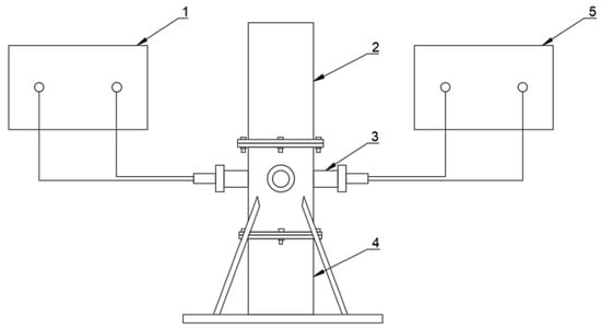
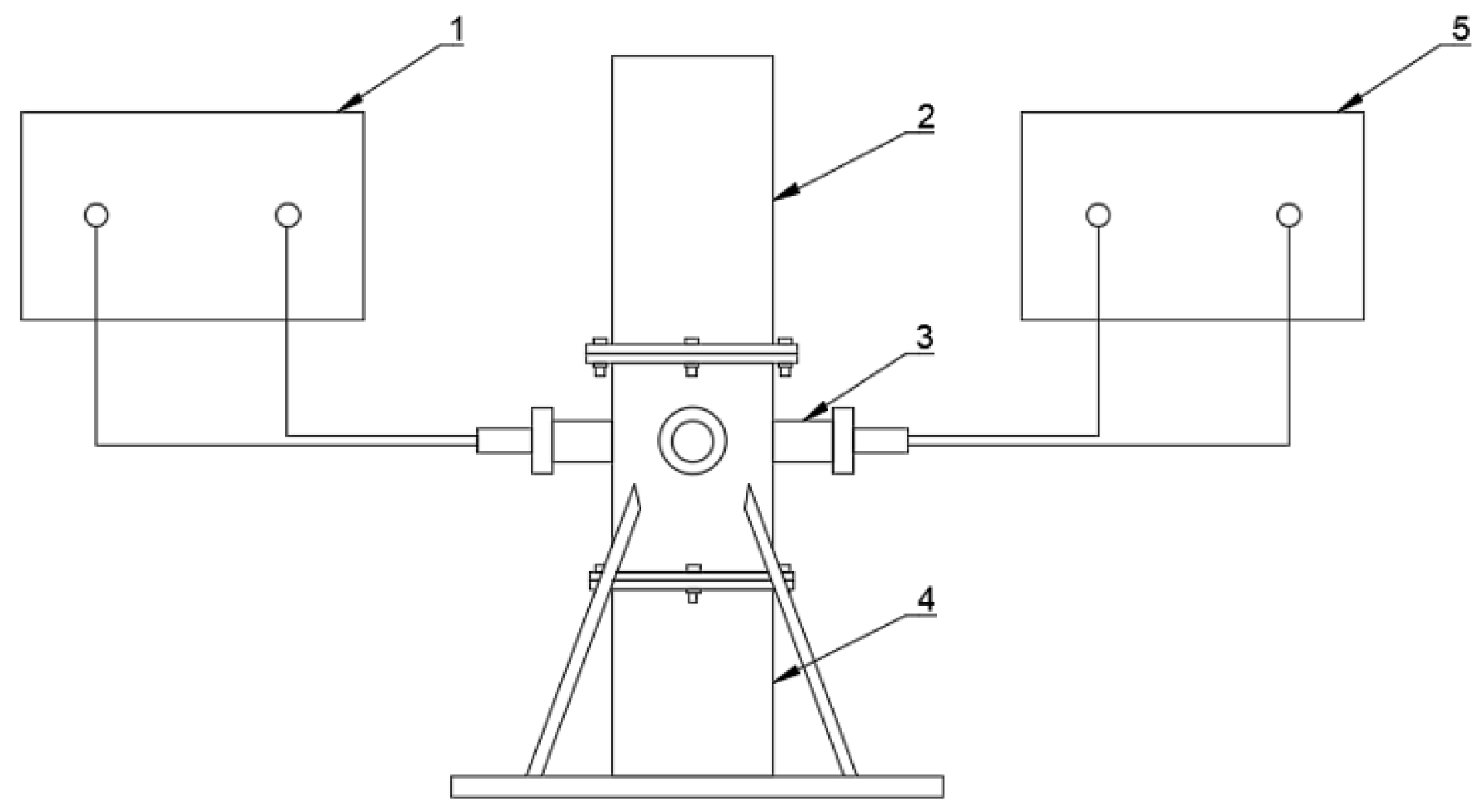
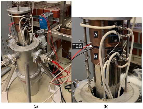
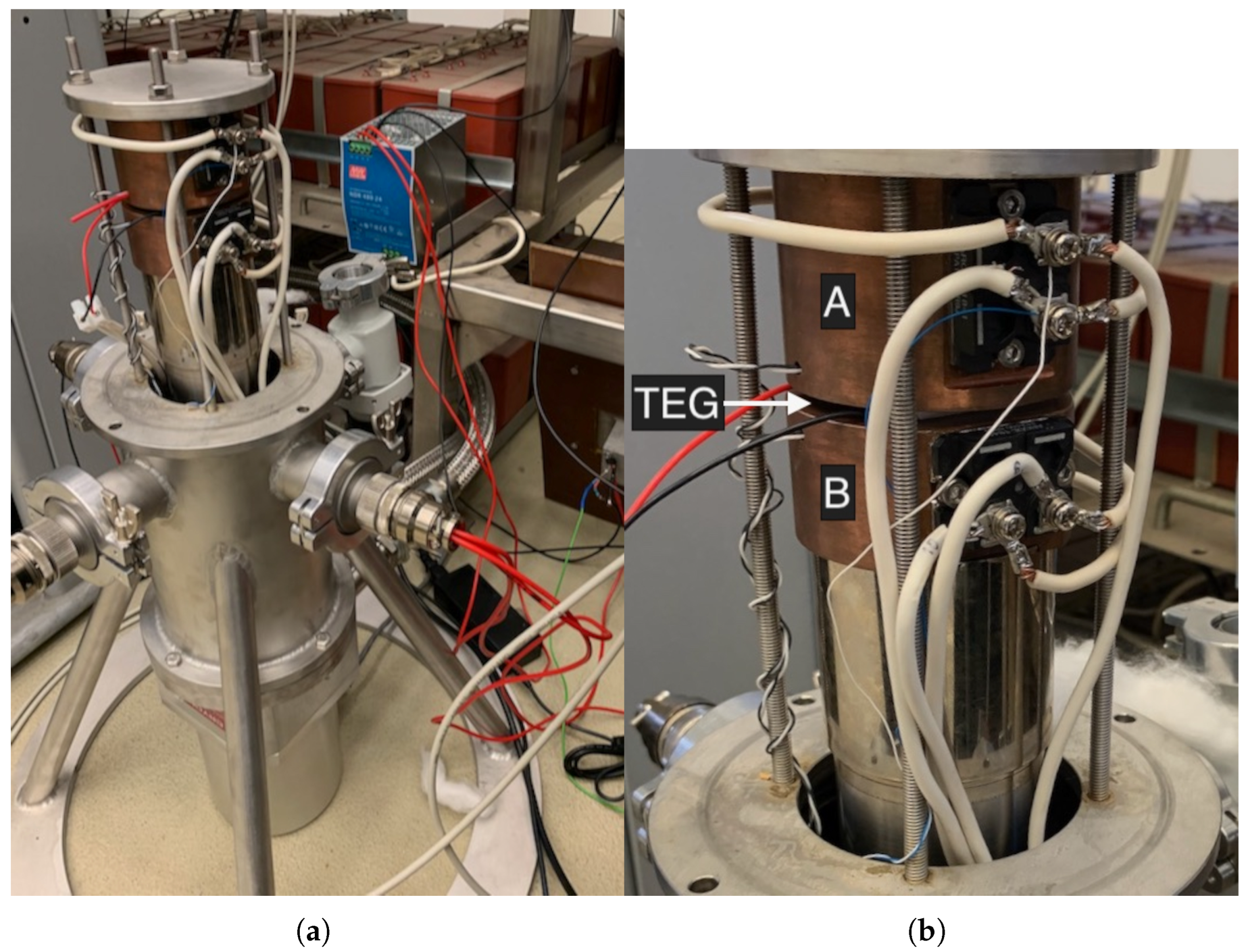
A measuring station has been designed and built to conduct tests assessing the efficiency of converting thermal energy into electrical energy in a thermoelectric generator. The station allows the operating conditions of thermoelectric cells to be simulated at different temperature levels on both the cold and hot sides. The main components of the station are a cryogenic refrigerator and a cryostat, which houses a TEG thermoelectric generator, measuring elements, and a heating element power control system. A schematic diagram of the station is shown in Figure 1. A view of the measuring part of the station inside the cryostat is shown in Figure 2.
Figure 1.
Test-stand schematic diagram: 1—electrical power output, 2—cryostat cover, 3—vacuum feedthrough, 4—Gifford-McMahon cryocooler, 5—heater power control system.
Figure 2.
Test-stand general view. The top copper cylinder (A) is the hot one and the bottom copper cylinder (B) is the cold one. The TEG module is placed between them. (a) View inside the cryostat. (b) Close-up of the TEG and heaters installation method.
The principle of operation of the test stand is to subject the thermoelectric module to heating on one side and cooling on the other. Heating is carried out using power resistors, while cooling is carried out using a Gifford-McMahon cryogenic refrigerator. The cryogenic refrigerator simulates the absorption of heat by evaporating liquefied natural gas. The temperature difference created on the TEG generates electricity. The measurement system allows the measurement of the thermal power supplied to the power resistors and the temperature on both sides of the thermogenerator. The measurement of the recovered electrical power is enabled by an adjustable resistor. The ratio of the recovered electrical power to the supplied thermal power determines the efficiency of the tested thermoelectric generator. The National Instruments LabVIEW environment was used to control the operation of the station and acquire measurement data.
During the experiment, the thermoelectric generator under testing is placed between two copper elements (Figure 2). The element above the TEG is a heating element on which the hot-side required temperature is set, while the element below the TEG is a cooling element that is in thermal contact with the low-temperature heat exchanger of the cryogenic cooler. On both sides of the two copper elements there are power resistors (ARCOL FPA100 6R8J, ARCOL, Truro, UK) used for precise hot-side and cold-side temperature control. Both temperatures are measured using resistance thermometers (PT100 Honeywell HEL-705-T-0-12-00, Honeywell, Charlotte, NC, USA) connected to a LakeShore Model 218 temperature monitor (LakeShore, Carson, CA, USA).
Despite careful monitoring and the use of fairly heavy copper components, the temperature on both sides fluctuated slightly while being maintained at a constant level during the measurements. After all measurements were completed, the following temperature fluctuation values were observed: temperature fluctuation range on the hot side—mean ± 0.24 K (min 0.10, max 0.50, std 0.16); temperature fluctuation range on the cold side—mean ± 0.22 K (min 0.10, max 0.37, std 0.14).
To ensure optimal thermal contact and minimize interface resistance under cryogenic conditions, Apiezon-N cryogenic vacuum grease was applied between the TEG surfaces and the copper blocks. All experiments were conducted in a high-vacuum environment ( Pa) to eliminate convective heat losses and focus the heat flux through the tested module. While the reported temperatures were measured within the copper blocks to maintain a uniform thermal reservoir, the resulting reflects the operational temperature gradient available from the heat source and sink, providing data representative of practical deployment conditions in mobile LNG systems.
The heat power supplied to the TEG was measured by measuring the electrical power consumed by the heating resistors on the hot side. For this purpose, the voltage drop across the resistors and the current flowing through the heating circuit were measured. This provided the power of the current converted into heat in the resistors. A MOSFET linear regulator was used to control the electric current. The electrical power recovered by the TEG was measured by measuring the voltage drop across an adjustable resistor with a known, preset resistance (TELPOD RDC100N-4R7). All electrical signals were measured and controlled using National Instruments (NI-9205, NI-9264) modules.
3. Test Procedure
The aim of the research was to determine the electrical power that the tested TEG modules are capable of delivering during LNG regasification and their efficiency in converting thermal energy into electrical energy. The research was divided into two cases:
- Part I—testing energy conversion parameters during LNG vaporization at a constant TEG cold-side temperature of 150 K;
- Part II—study of the impact of changes in the TEG’s cold-side temperature (above 150 K) on energy conversion parameters (gas reheating after the evaporation process).
A temperature of 150 K was selected because it corresponds to the evaporation temperature of LNG taken from a pressurized tank.
In addition, the impact of two different TEGs’ hot-side temperature levels on the efficiency of TEG modules was examined:
- In the case of heat being supplied to the TEG’s hot-side directly from the environment, a temperature of 283 K was assumed.
- In the case of heat transfer to the TEG’s hot-side from the cooling system of an NG-powered engine, a temperature of 340 K was assumed.
Six popular and inexpensive (less than $50) TEG modules were selected for testing. All thermoelectric modules were based on bismuth telluride (Bi2Te3) technology. Their dimensions were 4 cm by 4 cm. The selected modules are presented in Table 1.
Table 1.
Specifications of selected thermoelectric generators.
The measurement procedure consisted of placing the selected module between two copper elements. The cryostat was then closed and a vacuum of Pa was created inside. The vacuum was created to limit heat escape from the sides of the device and to ensure that all the heat energy supplied flowed through the module under testing. Next, a cryogenic cooler (with a temperature control system) was turned on to achieve the desired temperature (150 K) on the cold side. At the same time, the TEG module on the other side was heated to maintain the set temperature there (283 K or 340 K). Once the appropriate temperatures had been established and stabilized, the internal resistance () of the thermoelectric module was determined. The obtained value of the TEG’s internal resistance was set on an adjustable resistor to which the thermoelectric module was connected. Set in this way, the resistance value of the load resistor () remained constant throughout the entire measurement for a given module and temperature conditions.
The first part of the test consisted of maintaining a constant temperature on the cold side and reading the operating parameters of the tested module. Ten readings were taken every 20 min. The entire measurement series lasted 3 hours for each measurement. For each module, measurements were taken for both temperatures on the hot side (283 K and 340 K).
In part two, the temperature of the cold side was initially set at 150 K and then gradually increased to 230 K–260 K. Each reading of the operating parameters took place after the new temperature had stabilized (for about 20 min). In this case, too, measurements were taken for both temperatures (283 K and 340 K) on the hot side for each module.
For all these measurement cases, the electrical power on the load resistor and the efficiency of converting thermal energy into electrical energy were measured. The electrical power was calculated using the measured voltage drop across the load resistor and its known, previously set resistance:
where is the electrical power consumed at the load resistor, is the voltage drop across the load resistor, and is the TEG’s internal resistance.
The conversion efficiency was calculated as the ratio of the electrical power consumed to the heat power supplied:
The heat power supplied to the TEG module was calculated as the electrical power dissipated on the hot-side copper element by heating resistors:
where is the voltage drop across the heater resistor, and is the electrical current at the heater resistor.
4. Results and Discussion
The measurement results are presented below, divided into two cases: Part I—the electrical power and the efficiency during LNG vaporization at a constant TEG cold-side temperature of 150 K; Part II—the electrical power and efficiency during the increase in temperature on the cold side of the TEG (above 150 K) corresponding to overheating of evaporated LNG.
4.1. Part I—Constant TEG Cold-Side Temperature
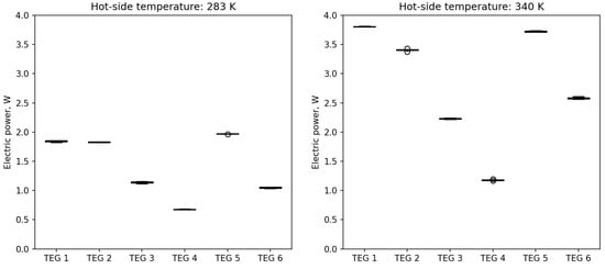
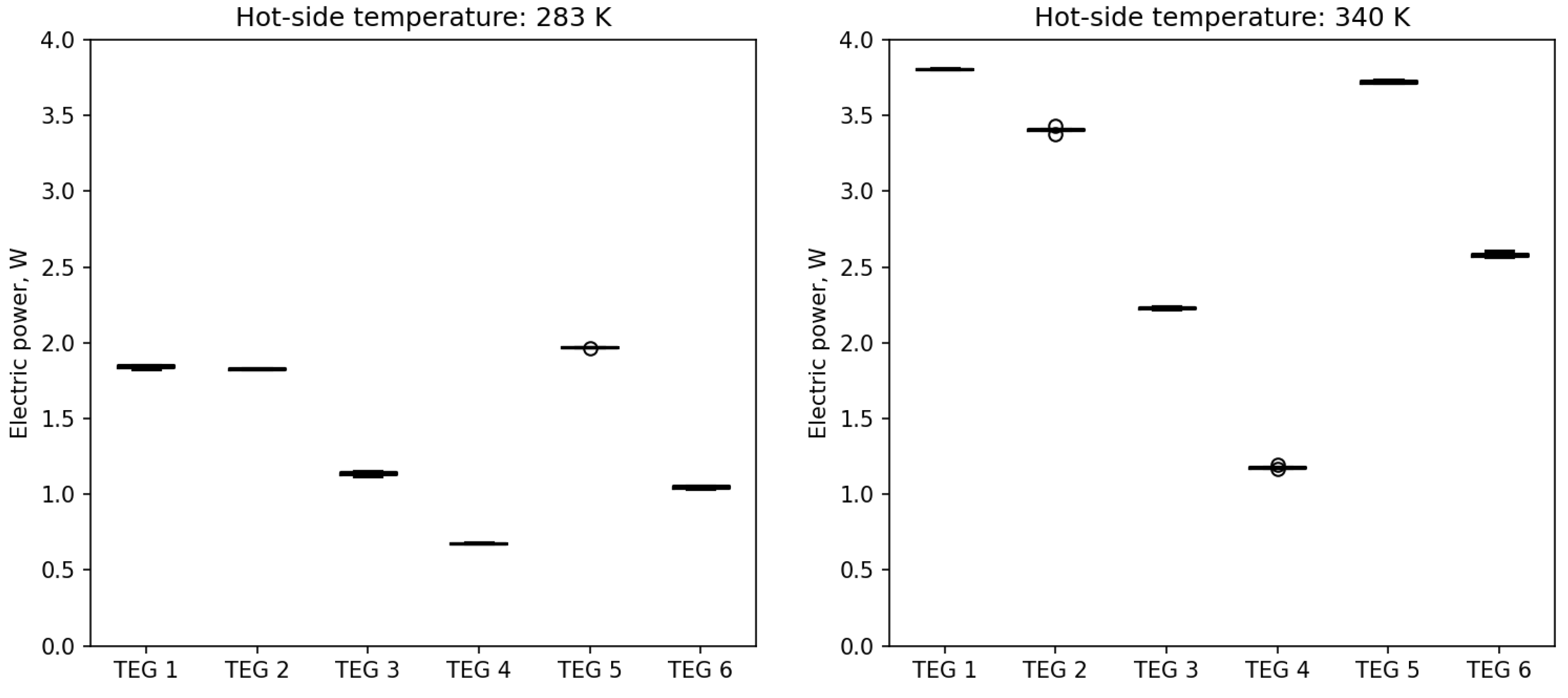
Figure 3 shows the results of the measurement of the electrical power consumed by the load resistor at a constant cold-side temperature of 150 K. The figure shows two cases of temperature settings on the hot side: 283 K on the left and 340 K on the right. The first temperature corresponds to the use of heat directly from the environment (atmospheric heat), while the second corresponds to the use of waste heat from the engine cooling system. The vertical axis scale is the same for both cases. The measurement data are presented as a box plot. It can be seen that the results for each sample were highly stable. Only a few outliers (circles) are visible. Significant differences in energy conversion efficiency can also be observed for different types of modules (TEG 1–TEG 6).
Figure 3.
Electric power of TEGs at constant cold-side temperature.
It can be noted that the electric power output is higher for the case with a greater temperature difference (340 K on the hot side). For TEGs 1–6, the increases are 100%, 79%, 100%, 100%, 90% and 150% respectively. It should be noted that for all TEGs, the power output more or less doubles (an increase of about 80–150%).
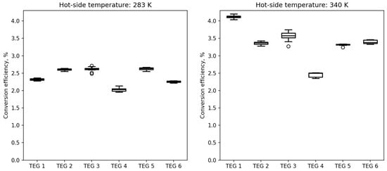
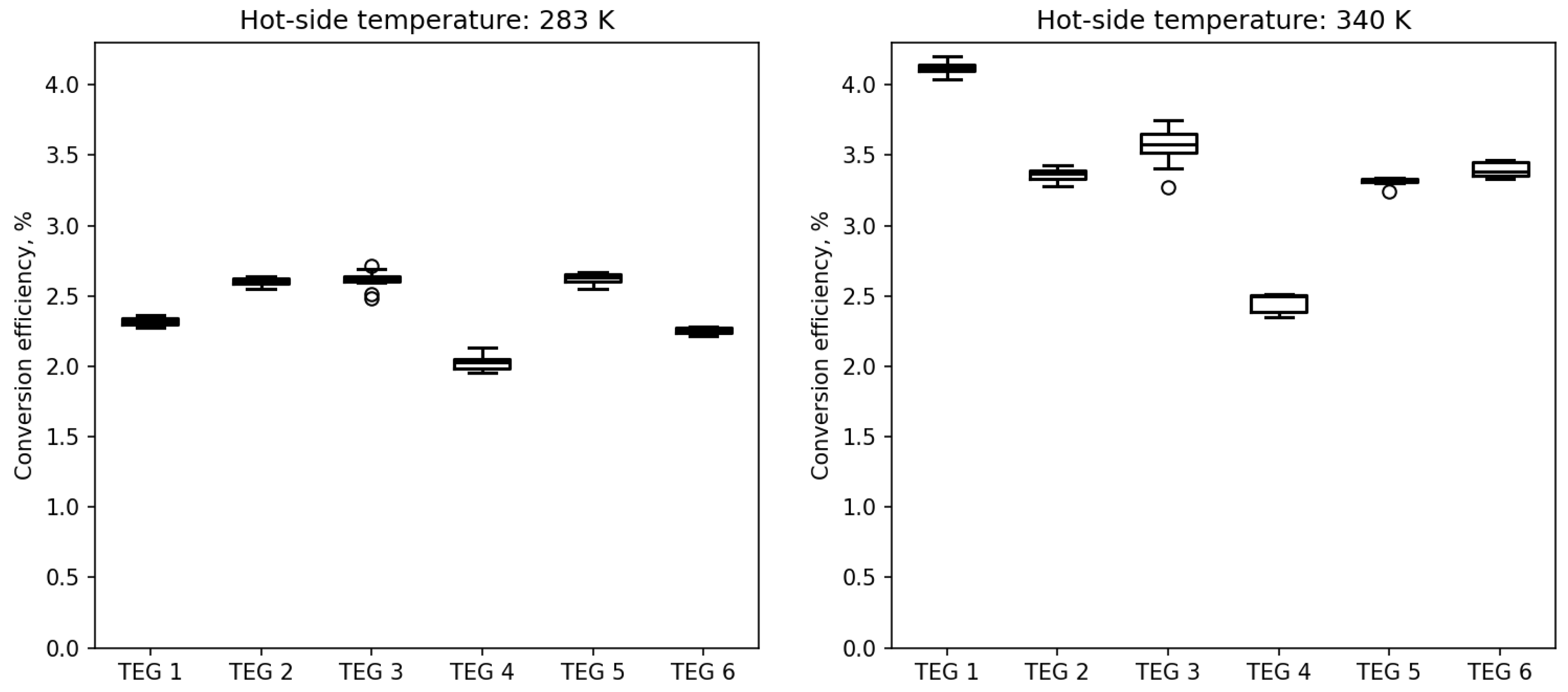
Figure 4 shows the efficiency of converting thermal energy into electrical energy at a constant temperature of 150 K on the cold side. The figure shows two cases of temperature settings on the hot-side: 283 K on the left and 340 K on the right. The vertical axis scale is the same for both cases. The data are presented in a manner similar to that of the previous figure. Despite differences between individual modules, it can be seen that the measured values remain roughly at a similar level.
Figure 4.
Energy conversion efficiency of TEGs at constant cold-side temperature.
As expected, the electrical efficiency increases with a larger temperature difference (340 K on the hot side). For TEGs 1–6, the improvements are 78%, 30%, 35%, 20%, 30% and 50% respectively. It is worth emphasizing that for TEG 1, the efficiency nearly doubles (an increase of about 80%).
The observed experimental trends align well with the theoretical framework established in earlier literature. Specifically, the near-doubling of power output when transitioning from ambient (283 K) to engine waste heat (340 K) confirms the thermodynamic sensitivity predicted by Rogala et al. [25]. However, the recorded efficiencies (2.0–4.0%) and power outputs are lower than the idealized theoretical limits. As identified in the [25] study, this quantitative difference stems from the fact that standard commercial modules are not geometrically optimized for cryogenic operation; theory suggests that reducing the leg length to 0.4–0.7 mm could enhance performance by over 50%. Consequently, the current results represent a ‘market-ready’ baseline, demonstrating that significant power recovery (up to 10 kW for marine vessels) is feasible even with standard, low-cost technology.
4.2. Part II—Variable TEG Cold-Side Temperature
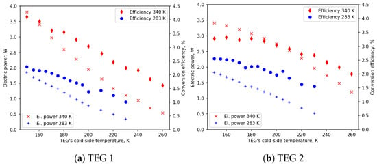
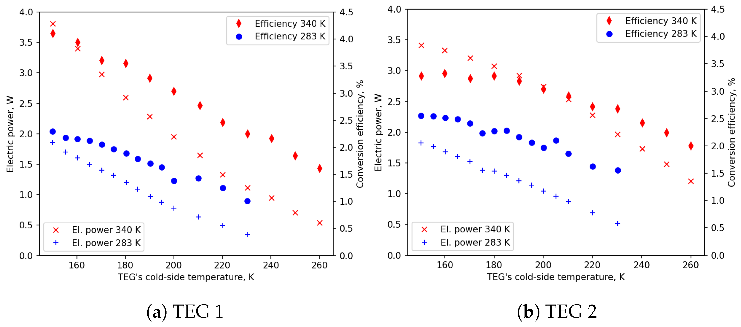
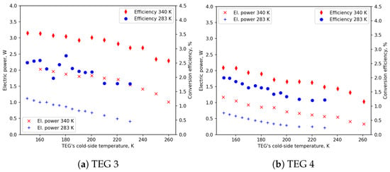
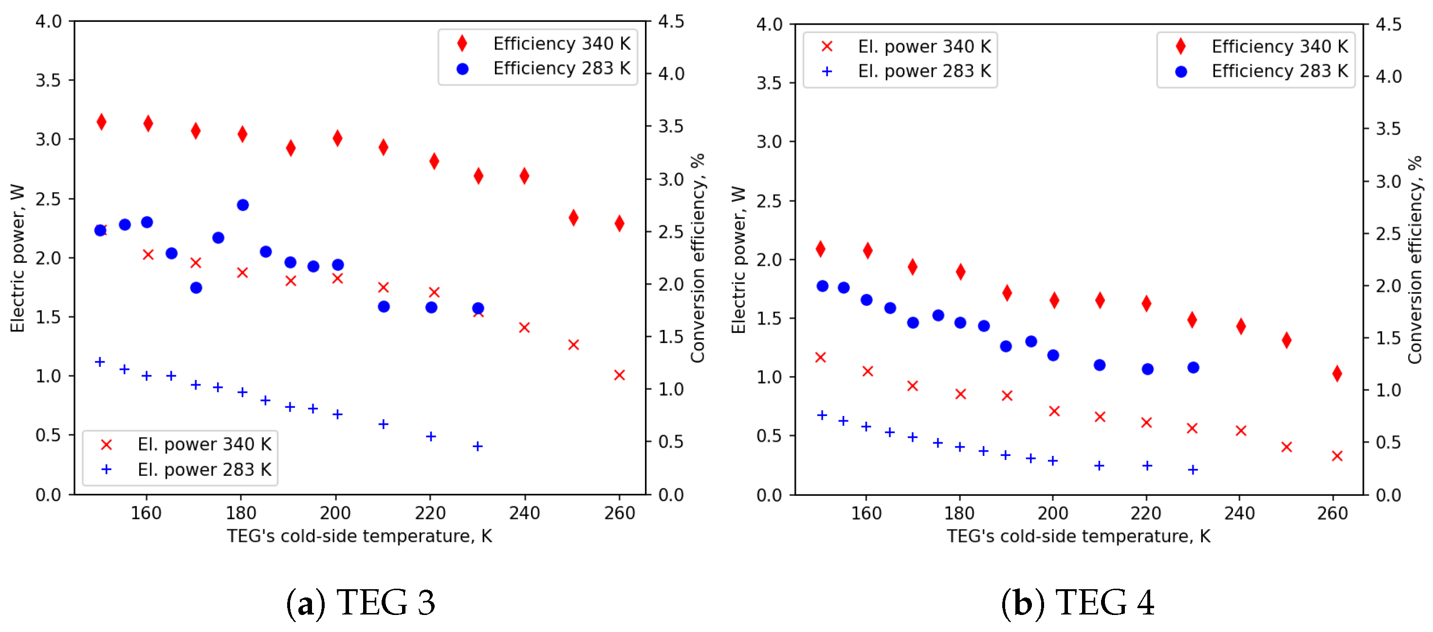
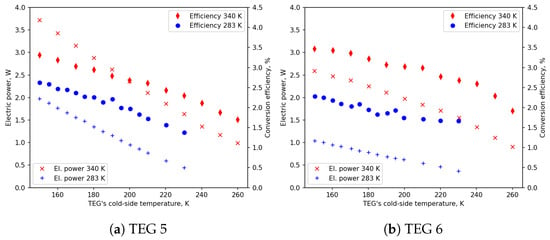
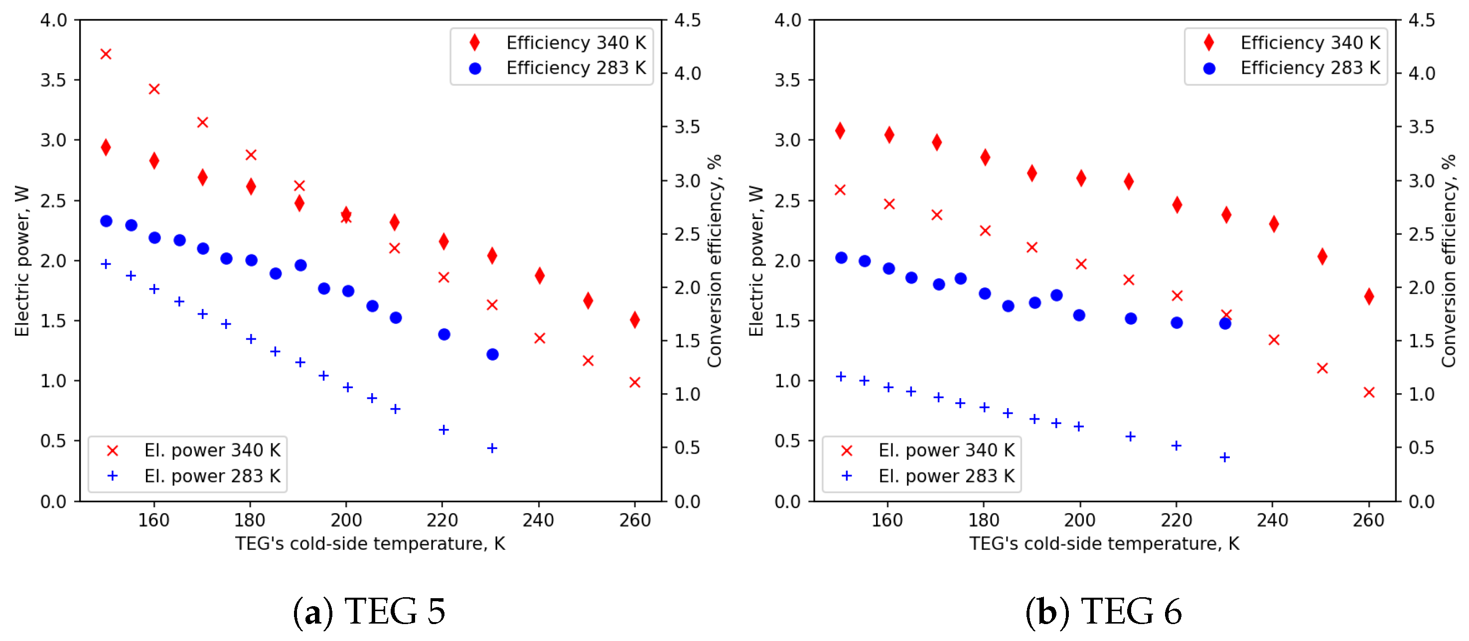
Figure 5, Figure 6 and Figure 7 show the results of measuring the electrical power consumed by the load resistor and the efficiency of converting thermal energy into electrical energy at a variable cold-side temperature (150 K and above) to simulate gas reheating after the evaporation process. In each figure, electrical power and efficiency are shown for both the lower hot-side temperature (283 K, blue markers) and the higher hot-side temperature (340 K, red markers). The temperature on the cold side was increased from 150 K to 230 K for the lower hot-side temperature (283 K) and to 260 K for the higher hot-side temperature (340 K). This difference was caused by the limited power of the heater on the cold side.
Figure 5.
Electric power and energy conversion efficiency of TEG 1 and TEG 2 at variable cold-side temperature.
Figure 6.
Electric power and energy conversion efficiency of TEG 3 and TEG 4 at variable cold-side temperature.
Figure 7.
Electric power and energy conversion efficiency of TEG 5 and TEG 6 at variable cold-side temperature.
In general, a relatively linear decrease in available electrical power and conversion efficiency can be observed as the temperature difference between the cold and hot sides decreases. According to the physics of the phenomenon, these parameters tend towards zero in the absence of a temperature difference. This relationship is very clearly visible for all types of modules in terms of electrical power consumption. In terms of conversion efficiency, certain fluctuations in values can be observed locally, most likely caused by larger errors during the measurement of heat energy flows.
It can be observed that the slopes of electric power for individual TEGs are similar for the considered hot-side temperatures and vary only slightly between the modules. The highest gradient is observed for TEGs 1 and 5 (see Table 2). It is worth noting that, in the case of LNG regasification, including the overheating of its gaseous form, it is more beneficial to use a TEG characterized by the lowest gradient, as it ensures the highest total exergy recovery, as in TEG 3.
Table 2.
The slope coefficients of the regression lines for each TEG in both temperature cases.
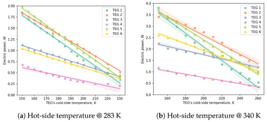
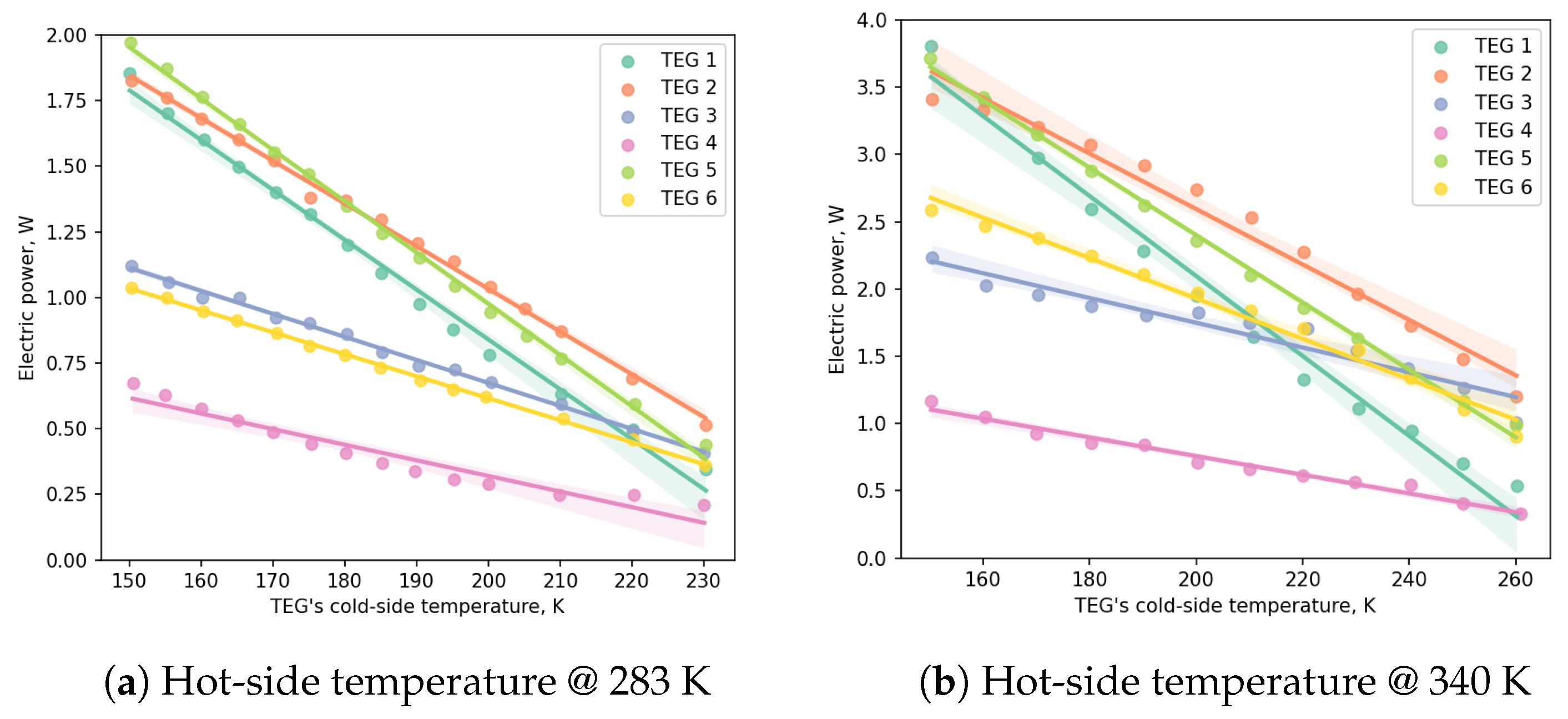
A summary of the available electrical power for all TEGs, categorized by the two hot-side temperature levels, is presented in Figure 8. A linear regression model was fitted to the measurement data. The figures display the resulting regression lines along with a 95% confidence interval, which confirms the high stability of the operating parameters of the tested modules and the reliability of the experimental data collected under cryogenic conditions.
Figure 8.
Electric power at variable cold-side temperature with regression lines and 95% confidence intervals.
The analysis of the obtained characteristics shows that for each module type, there is a nearly linear decrease in the generated electrical power as the cold-side temperature increases (i.e., as the temperature difference across the module decreases). This phenomenon is expected and consistent with the physics of thermoelectric conversion, where output parameters tend toward zero as the temperature gradient vanishes. Although the absolute values of the generated power at the higher hot-side temperature (340 K) are approximately twice as high as at 283 K, the dynamics of their decrease are also more pronounced.
Table 2 summarizes the slope coefficients of the regression lines, allowing for a quantitative assessment of each module’s sensitivity to changes in gas temperature: The largest power drops (highest gradients) were recorded for the TEG 1 (−0.030 at 340 K) and TEG 5 (−0.025 at 340 K) modules. This indicates that their performance degrades most rapidly as the evaporated LNG reheats.
In the context of optimizing the entire regasification process, modules with the lowest performance gradients are particularly beneficial, as they ensure a more stable energy supply across a wider temperature range. In this regard, the TEG 3 module stands out, as its slope coefficient is very low and remains constant (−0.009) regardless of the hot-side temperature.
Due to this characteristic stability, modules with a low gradient, such as TEG 3, are the most promising for maximizing total exergy recovery in systems that utilize both the latent heat of LNG vaporization and the energy from the gas overheating phase. The stability of these results, supported by the narrow confidence intervals in Figure 8, provides a solid foundation for designing scalable energy recovery systems for maritime and rail transport.
4.3. Electricity Recovery in Mobile Applications
Six types of thermoelectric modules were experimentally tested (Table 1). Under conditions of a fixed temperature difference (150 K on the cold side and 283 K or 340 K on the hot side), the tested modules demonstrated stable operation throughout the entire duration of the experiment (see Figure 3 and Figure 4). As the temperature on the cold side was increased, resulting in a smaller temperature difference between the two sides of the module, all tested TEGs showed a gradual and uniform decrease in performance, affecting both electrical power and efficiency.
Assuming the simplest design case of recovering only the latent heat of evaporation of LNG at a constant low-side temperature, the modules allow for a significant amount of electricity to be obtained. When the cell is heated by ambient heat (283 K), the electrical power ranges from 1 to 2 W with an energy conversion efficiency of 2% to 2.5% (Figure 4). However, utilizing the engine cooling system as a heat source (340 K) significantly boosts performance, with power outputs reaching 2 to 4 W and efficiencies increasing to the 3–4% range.
The experimental results indicate a high potential for economically viable heat recovery, particularly due to the technology’s inherent scalability. A standard TEG module measures 4 cm by 4 cm, resulting in a unit surface area of . By covering a selected area of LNG evaporators with an appropriate number of modules, the system can be precisely tailored to the power requirements of different mobile applications.
To evaluate this scalability, a detailed analysis was performed based on the average measured power: 1.5 W per module for 283 K and 3 W per module for 340 K. To contextualize these results within broader thermoelectric metrics, it is essential to jointly consider efficiency and power density [26]. While specialized high-performance devices can reach power densities of at a of 418 K [27], the commercial modules in this study achieved 0.13–0.24 at a much lower gradient of 190 K, demonstrating their efficiency for LNG applications. Furthermore, although high-temperature degradation is a critical concern for TEGs [28], the cryogenic and low-temperature range (<340 K) utilized here significantly reduces thermal stress, supporting the long-term reliability and stability required for maintenance-free mobile deployment.
The results, summarized in Table 3, show the following:
Table 3.
Possible amount of recovered electricity in mobile applications.
- Railway applications: To achieve an average power of 1 kW at 283 K, 670 modules are required, occupying a total surface area of . If waste heat at 340 K is used, the required surface for 1.5 kW of power drops to (500 modules).
- Marine applications: Due to significantly higher LNG consumption, a power output of 6.4 kW at 283 K can be achieved using 4270 modules (). At 340 K, a power of 10.0 kW is reachable with 3340 modules ().
As demonstrated by these values, the physical size of the heat exchanger is not a limiting factor for exergy recovery. The required surface area of approximately 0.53–1.07 per 1 kW of generated power is easily accommodated within the engine compartments of ships or locomotives. Consequently, the primary constraint on exergy recovery is the LNG fuel flow rate, which determines the available exergy stream, rather than the required exchanger dimensions. While this technology is highly feasible for rail and marine sectors, it remains less economically attractive for road transport, where LNG flow rates limit recoverable power to levels well below 100 W.
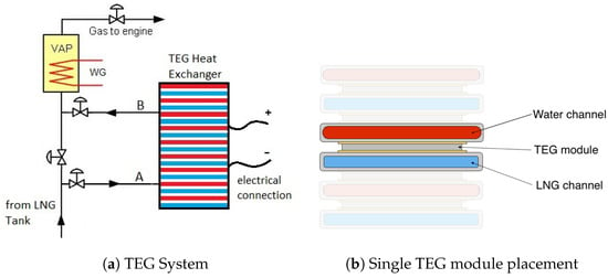
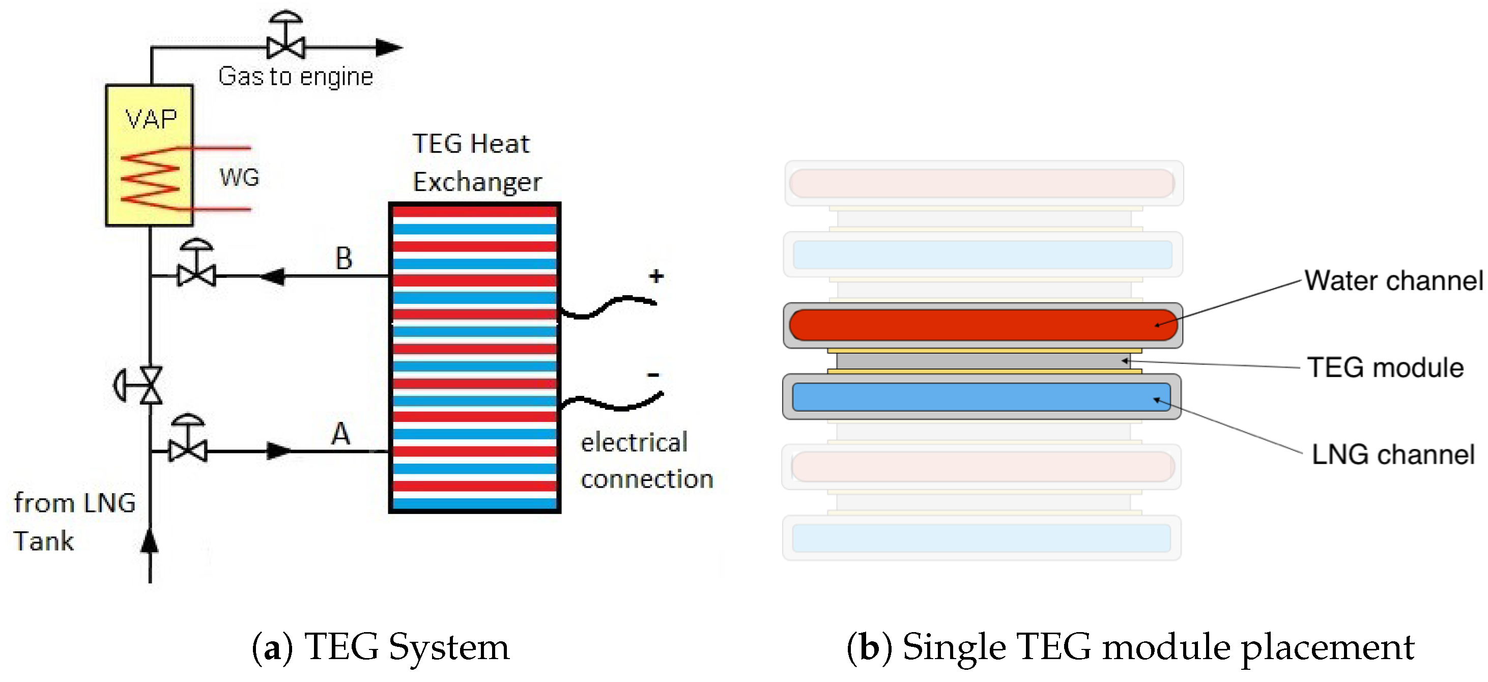
To provide the required heat flux, the TEG unit can be placed directly on the LNG process line, between the LNG tank and the main vaporizer, or on a dedicated TEG heat exchanger, as shown in Figure 9a. In this configuration, the TEG modules operate at a constant temperature, absorbing only the latent heat of LNG vaporization. Downstream of the TEG unit, a vaporizer (VAP) is installed to heat the cold gas to ambient temperature or to handle the full vaporization process in scenarios where the TEG heat exchanger is not operating (with bypass lines A and B closed).
Figure 9.
An exemplary connection of the TEG system to the main LNG Tank [3].
The TEG heat exchanger features a modular design to ensure that the total required heat transfer surface area is met for the desired power output. A detailed view of the installation of a single TEG module within the stack, highlighting the thermal contact between the LNG and heating channels, is shown in Figure 9b. Water acts as a medium for heat transfer between the heat source (the environment, engine cooling) and the TEG surface.
4.4. Economic and Ecological Analysis
The implementation of thermoelectric cold exergy recovery systems in mobile LNG applications must be evaluated not only through its technical feasibility but also through its economic and environmental impacts. As natural gas serves as a critical transition fuel in the effort to decarbonize the global transport sector, enhancing the efficiency of the LNG supply chain through TEG technology provides a pathway to further reduce the carbon footprint of marine and rail operations.
4.4.1. Economic Considerations and Scalability
The economic viability of the TEG system is highly dependent on the scale of the application and the intensity of LNG consumption. Based on the experimental results for the most efficient modules (e.g., TEG 3), the following economic factors are identified:
- Capital Expenditure (CAPEX): The tested TEG modules are commercially available with a unit price below $50. For a marine application aiming to recover 11.4 kW of power at K, approximately 3800 modules (assuming ∼3 W per module) are required. This results in a primary module cost of roughly $190,000. While additional costs for the integrated heat exchanger and power electronics must be considered, the absence of moving parts significantly reduces long-term maintenance costs (OPEX) compared to mechanical systems like Organic Rankine Cycles (ORCs).
- Operational Savings: In the maritime sector (consumption of 2000 kg/h LNG), the system can operate for approximately 6000 h per year. Assuming the recovered 11.4 kW replaces electricity generated by an auxiliary engine (AE) with 40% efficiency, the annual fuel saving amounts to 12.3 t of LNG. At a representative price of $600/t, this translates to $7380 in direct fuel savings annually.
- Sector Comparison:
- –
- Marine: High potential (up to 11.4 kW), suitable for large-scale modular heat exchangers (approx. 6.1 m2 of TEG surface).
- –
- Rail: Moderate potential (1.71 kW), requiring ∼560 modules. This can cover the auxiliary power needs of locomotive control systems.
- –
- Road: For truck transport (potential <100 W), the current CAPEX/watt ratio remains high, making it less attractive unless integrated into low-power sensor autonomy.
4.4.2. Ecological Impact and Sustainability
The ecological benefits of utilizing TEGs align with global GHG reduction targets (e.g., IMO 2050). The quantitative environmental impact is summarized below:
- Carbon Footprint Reduction: Using a standard emission factor for LNG (2.75 kg CO2 per 1 kg of fuel), the recovery of 11.4 kW in a marine vessel prevents the emission of approximately 33.8 tons of CO2 per year.
- Carbon Pricing Synergy: In the context of the EU Emissions Trading System (EU ETS), where carbon prices fluctuate around 80–100 EUR per ton, the system generates an additional indirect saving of approximately $3000–$3500 per year through avoided emissions costs.
- Energy Cascading: The ability to utilize waste heat from the engine cooling system ( K) to double the electricity output compared to ambient heat ( K) demonstrates a “circular” approach to energy. This increases the overall exergetic efficiency of the regasification process without requiring additional fuel.
- Reliability and Lifecycle: Thermoelectric generators are solid-state devices with high reliability and a typical lifespan exceeding 20 years. This minimizes the environmental impact associated with lubricant waste and frequent replacement of mechanical components.
4.4.3. Summary of Performance Indicators
To provide a clear overview of the proposed technology’s impact, Table 4 summarizes the key metrics for the three analyzed transport sectors.
Table 4.
Quantitative impact of TEG-based cold exergy recovery across different transport sectors.
In conclusion, while the economic payback period is currently influenced by low fuel prices, the integration of carbon taxes and the demand for autonomous, maintenance-free power sources in cryogenic systems make TEG technology a promising solution for the sustainable evolution of LNG-powered transport infrastructure.
5. Conclusions
The conducted experimental research confirmed the technical feasibility and potential of utilizing commercial thermoelectric generators (TEGs) to recover a significant portion of the cold exergy available during the LNG regasification process. Based on the comprehensive experimental data and subsequent scalability analysis, the following key findings and implications have been established:
- The developed specialized test stand, operating under high-vacuum conditions ( Pa), proved to be a robust tool for simulating LNG vaporization. It allowed for stable and repeatable measurements of TEG performance at cryogenic temperatures down to 150 K, providing a reliable environment for evaluating thermoelectric materials in conditions mimicking real-world LNG process lines.
- The temperature difference between the hot and cold sides of the module is the primary driver of performance. The experimental results demonstrated that increasing the hot-side temperature from 283 K (ambient heat) to 340 K (engine cooling waste heat) roughly doubled the electric power output for all tested modules. Specifically, average power outputs increased from approximately 1.5 W to 3.0 W per standard 4 × 4 cm module.
- Energy conversion efficiency also showed significant improvement with higher temperature gradients. While at 283 K the efficiency ranged between 2.0% and 2.5%, utilizing waste heat at 340 K allowed the modules to reach efficiencies of 3.0% to 4.0%. Notably, TEG 1 demonstrated the highest relative gain, with its efficiency nearly doubling under these conditions.
- A consistent, nearly linear decrease in both power output and conversion efficiency was observed as the cold-side temperature increased from 150 K to 260 K. This behavior is critical for system design during gas reheating phases. The analysis showed that modules with lower performance gradients, such as TEG 3, are particularly beneficial for maximizing total exergy recovery across the entire regasification and overheating range.
- The scalability analysis reveals that the physical dimensions of the heat exchanger are not a technical barrier to implementation. To generate 1 kW of electrical power, a total surface area of only 0.53–1.07 m2 is required, depending on the available heat source. Such dimensions are easily integrated into the existing engine room configurations of locomotives or marine vessels.
- The primary constraint on energy recovery is the LNG fuel flow rate rather than the thermoelectric technology itself. Consequently, the application is highly viable for large-scale transport:
- –
- In marine transport, power recovery can reach up to 10 kW.
- –
- In railway transport, potentials in the range of 1–1.7 kW were identified.
- –
- For road transport, the recoverable power remains below 100 W, which currently limits its economic feasibility in this sector.
- The proposed modular design of the TEG heat exchanger, integrated between the LNG tank and the main vaporizer, ensures that the system can be bypassed when necessary while maintaining constant operating temperatures for maximum efficiency.
Overall, these results demonstrate that thermoelectric cold exergy recovery during LNG regasification is a promising, maintenance-free, and scalable solution. It offers a viable supplementary energy source that enhances the overall thermodynamic efficiency and sustainability of LNG-powered mobile systems, particularly in high-consumption maritime and rail sectors.
Author Contributions
Conceptualization, W.G. and Z.M.; Methodology, W.G. and Z.M.; Formal analysis, W.G. and Z.M.; Investigation, W.G.; Data curation, W.G.; Writing—original draft, W.G.; Writing—review & editing, Z.M.; Supervision, Z.M. All authors have read and agreed to the published version of the manuscript.
Funding
This work was supported by the National Center for Research and Development, through the task “Optimization of systems supplying drives operating in maritime, road or rail transport, using natural gas in liquefied form”, contract no. POIR.01.01.01-00-0842/16-00, with statutory funds from the Ministry for Science and Higher Education.
Data Availability Statement
The original contributions presented in this study are included in the article. Further inquiries can be directed to the corresponding author.
Conflicts of Interest
The authors declare no conflicts of interest.
Abbreviations
The following abbreviations are used in this manuscript:
| NG | Natural gas |
| LNG | Liquefied natural gas |
| TE | Thermoelectric |
| TEG | Thermoelectric generator |
| Nomenclature | |
| List of symbols | |
| Voltage drop across the load resistor, V | |
| Voltage drop across the heater resistor, V | |
| Efficiency of converting thermal energy into electrical energy, - | |
| Electrical current at the heater resistor, A | |
| Electrical power consumed at the load resistor, W | |
| Heat power supplied to the TEG module, W | |
| Load resistor resistance, Ohm | |
| TEG’s internal resistance, Ohm |
References
- Kanbur, B.B.; Xiang, L.; Dubey, S.; Choo, F.H.; Duan, F. Cold utilization systems of LNG: A review. Renew. Sustain. Energy Rev. 2017, 79, 1171–1188. [Google Scholar] [CrossRef] [Scilit]
- International Gas Union. 2025 World LNG Report. Technical Report, International Gas Union. 2025. Available online: https://www.datocms-assets.com/146580/1751026179-igu-world-lng-report-2025-hr_dp_c.pdf (accessed on 16 February 2026).
- Banaszkiewicz, T.; Chorowski, M.; Gizicki, W.; Jedrusyna, A.; Kielar, J.; Malecha, Z.; Piotrowska, A.; Polinski, J.; Rogala, Z.; Sierpowski, K.; et al. Liquefied Natural Gas in Mobile Applications—Opportunities and Challenges. Energies 2020, 13, 5673. [Google Scholar] [CrossRef] [Scilit]
- Mokhatab, S.; Mak, J.Y.; Valappil, J.V.; Wood, D.A. Handbook of Liquefied Natural Gas; Elsevier/Gulf Professional Publishing: Amsterdam, The Netherlands; Houston, TX, USA, 2013. [Google Scholar]
- Livaniou, S.; Papadopoulos, G.A. Liquefied Natural Gas (LNG) as a Transitional Choice Replacing Marine Conventional Fuels (Heavy Fuel Oil/Marine Diesel Oil), towards the Era of Decarbonisation. Sustainability 2022, 14, 16364. [Google Scholar] [CrossRef] [Scilit]
- Brick, J.; Dediu, D.; Noffsinger, J. The Role of Natural Gas in the Move to Cleaner, More Reliable Power; Technical Report; McKinsey and Company: New York City, NY, USA, 2023. [Google Scholar]
- Verdolini, E.; Vona, F.; Popp, D. Bridging the Gap: Do Fast Reacting Fossil Technologies Facilitate Renewable Energy Diffusion? NBER Work. Pap. 2016, 22454. [Google Scholar] [CrossRef] [Scilit]
- International Energy Agency. Global Gas Security Review 2024. 2024. Available online: https://www.iea.org/reports/global-gas-security-review-2024 (accessed on 16 February 2026).
- Rogala, Z.; Brenk, A.; Malecha, Z. Theoretical and Numerical Analysis of Freezing Risk During LNG Evaporation Process. Energies 2019, 12, 1426. [Google Scholar] [CrossRef] [Scilit]
- Ouyang, T.; Tan, J.; Xie, S.; Wu, W.; Su, Z. A new scheme for large marine vessels LNG cold energy utilization from thermodynamic and thermoeconomic viewpoints. Energy Convers. Manag. 2021, 229, 113770. [Google Scholar] [CrossRef] [Scilit]
- Cleveland, C.J. In Proceedings of the Energy Dictionary, Expanded ed.; Morris, C., Ed.; Elsevier: Amsterdam, The Netherlands, 2009. [Google Scholar]
- Kaczmarek, R.; Stachel, A. The ORC power plant applied in the LNG re-gasification installation. Instal 2015, 2, 19–23. [Google Scholar]
- Dorosz, P.; Wojcieszak, P.; Malecha, Z. Exergetic Analysis, Optimization and Comparison of LNG Cold Exergy Recovery Systems for Transportation. Entropy 2018, 20, 59. [Google Scholar] [CrossRef] [Scilit] [PubMed]
- He, J.; Tritt, T.M. Advances in thermoelectric materials research: Looking back and moving forward. Science 2017, 357, eaak9997. [Google Scholar] [CrossRef] [Scilit] [PubMed]
- Zoui, M.A.; Bentouba, S.; Stocholm, J.G.; Bourouis, M. A Review on Thermoelectric Generators: Progress and Applications. Energies 2020, 13, 3606. [Google Scholar] [CrossRef] [Scilit]
- Dzulkfli, M.S.b.; Pesyridis, A.; Gohil, D. Thermoelectric Generation in Hybrid Electric Vehicles. Energies 2020, 13, 3742. [Google Scholar] [CrossRef] [Scilit]
- He, T.; Chong, Z.R.; Zheng, J.; Ju, Y.; Linga, P. LNG cold energy utilization: Prospects and challenges. Energy 2019, 170, 557–568. [Google Scholar] [CrossRef] [Scilit]
- Fu, Y.; Li, Y. Experimental Study on the Working Efficiency and Exergy Efficiency of the Vehicle-Mounted Thermoelectric Generator for Cold Chain Logistics Transportation Vehicle. Processes 2023, 11, 1782. [Google Scholar] [CrossRef] [Scilit]
- Zhang, T.; She, X.; You, Z.; Zhao, Y.; Fan, H.; Ding, Y. Cryogenic thermoelectric generation using cold energy from a decoupled liquid air energy storage system for decentralised energy networks. Appl. Energy 2022, 305, 117749. [Google Scholar] [CrossRef] [Scilit]
- Liu, Q.; He, Z.; Liu, Y.; He, Y. Thermodynamic and parametric analyses of a thermoelectric generator in a liquid air energy storage system. Energy Convers. Manag. 2021, 237, 114117. [Google Scholar] [CrossRef] [Scilit]
- Zhu, Y.; Li, J.; Ge, M.; Gu, H.; Wang, S. Numerical and experimental study of a non-frosting thermoelectric generation device for low temperature waste heat recovery. Appl. Energy 2023, 352, 121952. [Google Scholar] [CrossRef] [Scilit]
- Zhang, F.; Cai, H.; Yu, H.; Zhao, J.; Song, J.; Ji, D. Application of thermoelectric generators and organic Rankine cycle combined system for cold exergy recovery from liquefied natural gas. Energy 2025, 332, 137125. [Google Scholar] [CrossRef] [Scilit]
- Mohammadi, A.; Maleki, A. Performance Improvement of the LNG Regasification Process Based on Geothermal Energy Using a Thermoelectric Generator and Energy and Exergy Analyses. Sustainability 2024, 16, 10881. [Google Scholar] [CrossRef] [Scilit]
- He, Z.; Liu, S.; Qi, W.; Song, J.; Lai, C.; Feng, S.; Fu, L.; Zhang, Y.; Zhang, C.; Wu, Y. Numerical investigation of a novel micro-combustor with geometrically stretched and twisted channels for enhanced thermo-photovoltaic system performance. Appl. Therm. Eng. 2026, 291, 130230. [Google Scholar] [CrossRef] [Scilit]
- Rogala, Z.; Gizicki, W.; Sierpowski, K. Theoretical analysis of liquefied natural gas cold energy recovery using thermoelectric generators. Appl. Therm. Eng. 2022, 213, 118608. [Google Scholar] [CrossRef] [Scilit]
- Wang, Y.; Wu, X.; Yu, M.; Shen, X.; Wang, S.; Li, H.; Zhang, Z.; Liu, W. Thermoelectric cyclic-thermal regulation: A new operational mode of thermoelectric materials with high energy efficiency. Joule 2024, 8, 3201–3216. [Google Scholar] [CrossRef] [Scilit]
- Wu, X.; Wang, L.; Li, A.; Wu, G.; Hu, Z.; Yun, F.F.; Mori, T. High Conversion Efficiency in Intrinsic High Power-Density Mg2Sn-GeTe Thermoelectric Generator. Adv. Sci. 2025, 12, e06997. [Google Scholar] [CrossRef] [Scilit] [PubMed]
- Wu, X.; Ye, C.; Wang, Y.; Liao, Z.; Zhang, W.; Liu, W. Negative enthalpy delivering improved thermal stability for Mg2Sn-based thermoelectric power generator. Acta Mater. 2025, 289, 120865. [Google Scholar] [CrossRef] [Scilit]

Disclaimer/Publisher’s Note: The statements, opinions and data contained in all publications are solely those of the individual author(s) and contributor(s) and not of MDPI and/or the editor(s). MDPI and/or the editor(s) disclaim responsibility for any injury to people or property resulting from any ideas, methods, instructions or products referred to in the content. |
© 2026 by the authors. Licensee MDPI, Basel, Switzerland. This article is an open access article distributed under the terms and conditions of the Creative Commons Attribution (CC BY) license.